1
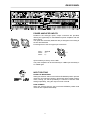
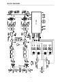
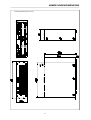
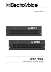
OWNER’S MANUAL
CPS 3 / CPS 4
CONTRACTOR PRECISION SERIES
IMPORTANT SAFETY INSTRUCTIONS
The lightning flash with arrowhead symbol, within an
equilateral triangle is intended to alert the user to the
presence of uninsulated “dangerous voltage” within the
product’s enclosure that may be of sufficient magnitude to
constitute a risk of electric shock to persons.
The exclamation point within an equilateral triangle is
intended to alert the user to the presence of important
operating and maintance (servicing) instructions in the
literature accompanying the appliance.
1.
2.
3.
4.
5.
6.
7.
8.
9.
10.
Read these instructions.
Keep these instructions.
Heed all warnings.
Follow all instructions.
Do not use this apparatus near water.
Clean only with a damp cloth.
Do not block any of the ventilation openings.
Install in accordance with the manufactures instructions.
Do not install near any heat sources such as radiators, heat registers, stoves, or other apparatus that produce heat.
Only use attachments/accessories specified by the manufacturer.
Refer all servicing to qualified service personnel. Servicing is required when the apparatus has been
damaged in any way, such as power-supply cord or plug is damaged, liquid has been spilled or objects have fallen
into the apparatus, the apparatus has been exposed to rain or moisture, does not operate normally, or has
been dropped.
For US and CANADA only:
Do not defeat the safety purpose of the grounding-type plug. A grounding type plug has two blades and a third grounding prong.
The wide blade or the third prong are provided for your safety. When the provided plug does not fit into your outlet, consult an
electrican for replacement of the absolete outlet.
IMPORTANT SERVICE INSTRUCTIONS
CAUTION: These servicing instructions are for use by qualified personnel only. To reduce the risk of
electric shock, do not perform any servicing other than that contained in the Operating
Instructions unless you are qualified to do so. Refer all servicing to qualified service
personnel.
1. Security regulations as stated in the EN 60065 (VDE 0860 / IEC 65) and the CSA E65 - 94 have to be obeyed when
servicing the appliance.
2. Use of a mains separator transformer is mandatory during maintenance while the appliance is opened, needs to be
operated and is connected to the mains
3. Switch off the power before retrofitting any extensions, changing the mains voltage or the output voltage.
4. The minimum distance between parts carrying mains voltage and any accessible metal piece (metal enclosure),
respectively between the mains poles has to be 3 mm and needs to be minded at all times.
The minimum distance between parts carrying mains voltage and any switches or breakers that are not connected
to the mains (secondary parts) has to be 6 mm and needs to be minded at all times.
5. Replacing special components that are marked in the circuit diagram using the security symbol (Note) is only permissible
when using original parts.
6. Altering the circuitry without prior consent or advice is not legitimate.
7. Any work security regulations that are applicable at the location where the appliance is being serviced have to be strictly
obeyed. This applies also to any regulations about the work place itself.
8. All instructions concerning the handling of MOS - circuits have to be observed.
Note:
SAFETY COMPONENT (HAS TO BE REPLACED WITH ORIGINAL PART ONLY)
8
DESCRIPTION
CONTENTS
Introduction . . . . . . . . . . . . . . . . . . . . . . . . . . . . . . . . . . . . . . . . . . . . . . . . . . . . . . . . . .
Front Panel. . . . . . . . . . . . . . . . . . . . . . . . . . . . . . . . . . . . . . . . . . . . . . . . . . . . . . . . . . .
Rear Panel . . . . . . . . . . . . . . . . . . . . . . . . . . . . . . . . . . . . . . . . . . . . . . . . . . . . . . . . . . .
Specifications . . . . . . . . . . . . . . . . . . . . . . . . . . . . . . . . . . . . . . . . . . . . . . . . . . . . . . . . .
Block diagram . . . . . . . . . . . . . . . . . . . . . . . . . . . . . . . . . . . . . . . . . . . . . . . . . . . . . . . .
Dimensions . . . . . . . . . . . . . . . . . . . . . . . . . . . . . . . . . . . . . . . . . . . . . . . . . . . . . . . . . .
Warranty. . . . . . . . . . . . . . . . . . . . . . . . . . . . . . . . . . . . . . . . . . . . . . . . . . . . . . . . . . . . .
9
10
11
13
20
21
24
DESCRIPTION
First of all, we would like to express our thanks and at the same time congratulate you on the decision to
buy one of our CONTRACTOR PRECISION SERIES power amplifiers.
Electro-Voice CONTRACTOR PRECISION SERIES amplifiers are made to meet the highest requirements of any on-the-road application. Thus they provide on-board protection against thermal and
capacitive overload, short-circuit and the occurrence of HF or DC at the output. Additionally, special
circuitry prevents the output-stage transistors from being damaged by Back-EMF. During soft start,
delayed switching of the power outputs is accomplished via relays and a limiter controls the initial current
inrush, preventing the mains fuse from being blown during the power-on operation.
The mechanical construction as well is carried out following the highest precision standards of the industry.
The robust steel chassis provides extreme rigidity and it is meant to live through any hard wearing condition
of a touring application. Thermal stability is guaranteed by two 4-Mode silently running fans that offer the
possibility to also use the amplifiers in a studio environment.
The extensive comparator circuitry constantly monitors the input and output signals and activates the
internal limiters whenever a non-linear operational state is encountered. This provides reliable protection
of the connected loudspeaker systems against overload and clipping. The sound quality of the CONTRACTOR PRECISON SERIES power amplifiers is superb. Using comprehensive dimensioned power
supply units with low-interference toroidal transformers gains a headroom that exceeds the nominal power
handling capacity by far. No V/I-Foldback-Limiter circuits are employed within the power amplifiers, making
it possible to operate the amps on complex loads up to ±90° phase angles without a problem.
The input facilities are carried out as balanced XLRF-type sockets while the Direct-Outs – on which the
carried-through signals are present – come as XLRM-type connectors. Using the Input Routing-switches
lets you determine if the CONTRACTOR PRECISION SERIES amplifiers are operated in DUAL (stereo)
or PARALLEL (monaural) mode; “mono-bridged” operation is also possible.
The dB-scaled level controls are to be found on the rear panel. These potentiometers guarantee precise
and reliable operation. The easy readable LED display offers quick optical information on the power
amplifiers’ momentary operational mode. For each channel individually the display shows whether they
are operational, a signal is present at the outputs, when the limiters are activated, and whether one of the
protection circuits has been engaged or not. The power outputs CANNEL A, CHANNEL B and BRIDGED
OUT are carried out as Speakon connectors. A ground-lift switch that separates the enclosure from the
appliance’s ground potential and therefore helps to eliminate ground noise loops and the mono bridged
mode switch are also located on the rear panel. In normal operation all CONTRACTOR PRECISION
SERIES power amplifiers can be used to drive loads down to 2 ohms; in bridged mode the minimal load
is 4 ohms. All amps are equipped with extremely silent running fans providing front-to-rear air circulation,
guaranteeing trouble-free operation even in smaller power amplifier rack systems.
Studying this owner’s manual carefully will provide you with further and more detailed information about
the CONTRACTOR PRECISION SERIES power amplifiers. Thus we recommend to keep on reading,
assuring you that the Electro-Voice CONTRACTOR PRECISION SERIES power amplifiers will provide
you with a lot of fun and satisfaction in your work.
9
FRONT PANEL
1. Level Control
To prevent unauthorized operation of the level controls on the CPS3 and CPS4, they are provided with
screwed-on protective cover lids. When shipped from the factory, the detented potentiometers are set to
their clockwise limits. Thus, the input signal is not attenuated. In case matching the input levels is required,
you first have to detach (unscrew) the cover lids to gain access to the potentiometers.
2. POWER ON INDICATION
This LED lights up when the mains switch is pressed. If it does not light up, the unit is not connected to
the mains or the mains fuse has blown.
3. INPUT INDICATION
This LED lights up if a signal is present at the power amplifier input. The indicator does not light up when
the input controls are turned down completely.
4. OUTPUT INDICATION
This LED lights up if a signal is present at the power amplifier output. The indicator goes off when the
speaker line has shorted or a protective circuit has been activated thus indicating that there is no signal
at the speaker output terminals.
5. LIMIT
This LED lights up if the limiter has been activated and the power amplifier is being operated at the clip
level. If the LED flashes briefly, this is not a cause for concern. If this LED is lit permanently, the volume
should be reduced to avoid overload damages to the connected loudspeaker systems.
6. PROTECT
When this LED lights up during operation, one of the protection circuits against over-temperature,
overload, shorted outputs, radio frequency interference or DC faults has been triggered. The cause of the
error e.g. a shorted loudspeaker line must be remedied. In case of overheating, wait a little until the
amplifier switches back to operating mode itself.
7. POWER Switch
The unit is switched on via the power switch. The loudspeaker outputs are switched on via delayed relays
so that no startup transients are audible. A current limiter prevents startup peaks on the mains line and
prevents the mains fuse from blowing.
10
REAR PANEL
POWER AMPLIFIER INPUTS
Parallel to the XLR-type inputs, output connectors are provided,
offering the opportunity to feed additional power amplifiers with the
same signal.
The inputs are electrically balanced with pin-assignment according to
the IEC 268 standard.
Pin-assignment of the XLR-type input connectors:
PIN 1:
PIN 2:
PIN 3:
SHIELD
a, +
b, -
Input sensitivity is factory set to 0 dBu.
The power amplifier can be set internally to +6dBu input sensitivity or
to +26dBu gain.
INPUT ROUTING
PARALLEL MONAURAL
Setting the selector switch to the PARALLEL/MONO position puts the
channel A and channel B inputs in electrically direct parallel configuration, leaving you still the possibility to control the channels’ level
settings separately, using the output controls A and B.
DUAL STEREO
When the selector switch is set to its DUAL/STEREO position both
channels are amplified individually.
11
REAR PANEL
POWER AMPLIFIER OUTPUT CONNECTORS
SPEAKON output connectors are provided for the power
amplifier channels A (left) and B (right).
The Bridged Out Connector for bridged operation is
sealed with a plastic cover to prevent connection errors.
LIMITER
The time constant of the built-in limiter to avoid overdriving is adjustable. Position “SLOW” is the factory preset
and this should also be the normal position.
If the power amplifier is used as a MID/HI-frequency
amplifier in active multi-way systems, the limiter switch
should be set to “FAST”.
If the power amplifier is used as LOW-frequency amplifier in active multi-way systems, the limiter switch should
be set to “SLOW”.
BRIDGED MODE
Slide switch to change from Normal Stereo mode to
Bridged mode. In Bridged mode the built-in power amplifiers operate in “push- pull” and the double output voltage
from channel A and B appears at the Bridged output
connector. The phases of Channel A and B are in opposite and therefore the individual channels must not be
used as loudspeaker outputs.
HI-LO-CUT FILTER
This filter attenuates subsonic and high frequency signals so that the power amplifiers are not modulated with
these signals. This switch should normally always be in
position ON. The OFF position is only for applications
where an upstream unit, e.g. a crossover or a equalizer,
has integrated HI-Cut and LO-Cut filters.
GROUNDLIFT SWITCH
Hum loops can be avoided with the groundlift switch. If
the power amplifier is operated together with other units
in one 19" rack, the switch should be in GROUNDED
position. If the power amplifier is used with units which
have different earthing potentials, the switch should be
adjusted to the UNGROUNDED position.
12
SPECIFICATIONS
Technical Specifications: CPS3, CPS4
Amplifier at rated conditions, both channels driven with 8 ohms loads, unless otherwise specified.
CPS3
CPS4
Load Impedance
8Ω
4Ω
2Ω
8Ω
4Ω
Maximum Midband Output Power
THD=1%, 1kHz
560W
900W
1200W
850W
1300W 1800W
Rated Output Power
THD< 0.1%, 20Hz ... 20kHz
500W
800W
1000W
750W
1200W 1500W
Maximum Bridged Output Power
THD=1%, 1kHz
1800W 2400W ———
2600W 3600W ———
Maximum RMS Voltage Swing
THD=1%, 1kHz
72V
91V
Voltage Gain
at 1 kHz
37dB
39dB
Slew Rate
35V/µs
40V/µs
Power Consumption
at 1/8 maximum output power @ 4 Ω
1300W
1850W
Input Sensitivity
at rated output power @ 4 Ω, 1 kHz
0dBu ( 775mV)
THD at rated output power,
MBW=80kHz, 1 kHz
< 0.05 %
IMD-SMPTE
60 Hz, 7 kHz
< 0.01 %
DIM30
3.15kHz, 15 kHz
< 0.01 %
Crosstalk
ref. 1kHz, at rated output power
<-70 dB
Frequency Response
-1dB, ref. 1 kHz
13Hz ... 40kHz
Power Bandwith
THD=1%, ref. 1kHz, half power @ 4 Ω
10Hz ... 48kHz
Input Impedance
20Hz ... 20 kHz, balanced
20kΩ
Damping Factor
at 100Hz / 1kHz
>400 / >300
Signal to Noise Ratio
A-weighted
105dB
Power Requirements
230V, 50Hz ... 60Hz
Protection
Audio limiters, High temperature, DC, HF, Back-EMF,
Peak current limiters, Inrush current limiters, Turn-on delay
Front-to-Rear, 4-stage-fans
Cooling
Safety Class
I
Dimensions (W x H x D), mm
483 x 132.5 x 385.5
Weight
Retrofitting kit
2Ω
27kg
Input Transformers
29kg
NRS 90176
13
BLOCK DIAGRAM
20
ABMESSUNGEN/DIMENSIONS
Abmessungen/Dimensions (in mm)
21