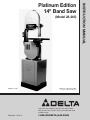
1
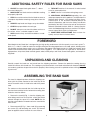
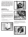
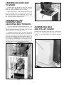
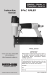
(Model 28-263)
DATED 4-15-00
PART NO. 426-02-651-0037
Copyright © 2000 Delta Machinery
If you have any problems with your new Delta Power
Tool, please call us toll free. Have your model and serial
numbers ready.
FRANÇAIS : PAGE 17
1-800-GO-DELTA (463-3582)
INSTRUCTION MANUAL
Platinum Edition
14" Band Saw
SAFETY RULES
Woodworking can be dangerous if safe and proper operating procedures are not followed. As with all machinery, there are certain
hazards involved with the operation of the product. Using the machine with respect and caution will considerably lessen the possibility of personal injury. However, if normal safety precautions are overlooked or ignored, personal injury to the operator may result.
Safety equipment such as guards, push sticks, hold-downs, featherboards, goggles, dust masks and hearing protection can reduce
your potential for injury. But even the best guard won’t make up for poor judgment, carelessness or inattention. Always use common sense and exercise caution in the workshop. If a procedure feels dangerous, don’t try it. Figure out an alternative procedure
that feels safer. REMEMBER: Your personal safety is your responsibility.
This machine was designed for certain applications only. Delta strongly recommends that this machine not be modified and/or used
for any application other than that for which it was designed. If you have any questions relative to a particular application, DO NOT
use the machine until you have first contacted Delta to determine if it can or should be performed on the product.
Technical Service Manager
Delta Machinery
4825 Highway 45 North
P. O. Box 2468
Jackson, TN 38302-2468
(In Canada: 505 Southgate Drive, Guelph, Ontario N1H 6M7)
WARNING: FAILURE TO FOLLOW THESE RULES
MAY RESULT IN SERIOUS PERSONAL INJURY
1. FOR YOUR OWN SAFETY, READ INSTRUCTION
MANUAL BEFORE OPERATING THE TOOL. Learn the
tool’s application and limitations as well as the specific
hazards peculiar to it.
15. MAINTAIN TOOLS IN TOP CONDITION. Keep tools
sharp and clean for best and safest performance. Follow
instructions for lubricating and changing accessories.
16. DISCONNECT TOOLS before servicing and when
changing accessories such as blades, bits, cutters, etc.
2. KEEP GUARDS IN PLACE and in working order.
17. USE RECOMMENDED ACCESSORIES. The use of
accessories and attachments not recommended by Delta
may cause hazards or risk of injury to persons.
3. ALWAYS WEAR EYE PROTECTION.
4. REMOVE ADJUSTING KEYS AND WRENCHES. Form
habit of checking to see that keys and adjusting wrenches
are removed from tool before turning it “on.”
18. REDUCE THE RISK OF UNINTENTIONAL STARTING. Make sure switch is in “OFF” position before plugging
in power cord.
5. KEEP WORK AREA CLEAN. Cluttered areas and
benches invite accidents.
19. NEVER STAND ON TOOL. Serious injury could occur
if the tool is tipped or if the cutting tool is accidentally
contacted.
6. DON’T USE IN DANGEROUS ENVIRONMENT. Don’t
use power tools in damp or wet locations, or expose them
to rain. Keep work area well-lighted.
20. CHECK DAMAGED PARTS. Before further use of the
tool, a guard or other part that is damaged should be carefully checked to ensure that it will operate properly and
perform its intended function – check for alignment of moving parts, binding of moving parts, breakage of parts,
mounting, and any other conditions that may affect its operation. A guard or other part that is damaged should be
properly repaired or replaced.
7. KEEP CHILDREN AND VISITORS AWAY. All children
and visitors should be kept a safe distance from work area.
8. MAKE WORKSHOP CHILDPROOF – with padlocks,
master switches, or by removing starter keys.
9. DON’T FORCE TOOL. It will do the job better and be
safer at the rate for which it was designed.
21. DIRECTION OF FEED. Feed work into a blade or cutter
against the direction of rotation of the blade or cutter only.
10. USE RIGHT TOOL. Don’t force tool or attachment to
do a job for which it was not designed.
22. NEVER LEAVE TOOL RUNNING UNATTENDED. TURN
POWER OFF. Don’t leave tool until it comes to a complete
stop.
11. WEAR PROPER APPAREL. No loose clothing, gloves,
neckties, rings, bracelets, or other jewelry to get caught in
moving parts. Nonslip footwear is recommended. Wear
protective hair covering to contain long hair.
23. DRUGS, ALCOHOL, MEDICATION. Do not operate
tool while under the influence of drugs, alcohol or any
medication.
12. ALWAYS USE SAFETY GLASSES. Wear safety glasses.
Everyday eyeglasses only have impact resistant lenses;
they are not safety glasses. Also use face or dust mask if
cutting operation is dusty. These safety glasses must conform to ANSI Z87.1 requirements. Note: Approved glasses
have Z87 printed or stamped on them.
24. MAKE SURE TOOL IS DISCONNECTED FROM POWER
SUPPLY while motor is being mounted, connected or reconnected.
13. SECURE WORK. Use clamps or a vise to hold work
when practical. It’s safer than using your hand and frees
both hands to operate tool.
25. WARNING: The dust generated by certain woods and
wood products can be injurious to your health. Always operate machinery in well ventilated areas and provide for proper
dust removal. Use wood dust collection systems whenever
possible.
14. DON’T OVERREACH. Keep proper footing and balance at all times.
26. WHEN THE UNIT IS NOT IN USE the switch should be
locked in the “OFF” position to prevent unauthorized use.
2
ADDITIONAL SAFETY RULES FOR BAND SAWS
1. ADJUST the upper blade guide about 1/8 above
the material being cut.
8. TURN OFF machine if the material is to be backed
out of an uncompleted cut.
2. MAKE SURE that blade tension and blade tracking
are properly adjusted.
9. MAKE “release” cuts before cutting long curves.
10. ADDITIONAL INFORMATION regarding the safe
and proper operation of this product is available from the
National Safety Council, 1121 Spring Lake Drive, Itasca,
IL 60143-3201 in the Accident Prevention Manual for
Industrial Operations and also in the Safety Data Sheets
provided by the NSC. Please also refer to the American
National Standards Institute ANSI 01.1 Safety Requirements for Woodworking Machinery and the U.S. Department of Labor OSHA 1910.213 Regulations.
3. STOP the machine and wait for the blade to come to
a complete stop before removing scrap pieces from the
table.
4. ALWAYS keep hands and fingers away from blade.
5. CHECK for proper blade size and type.
6. DO NOT attempt to saw stock that does not have a
flat surface, unless a suitable support is used.
11. SAVE THESE INSTRUCTIONS. Refer to them frequently and use them to instruct others.
7. HOLD material firmly and feed into blade at a moderate speed.
FOREWORD
Delta Model 28-263 Band Saw is designed to give high quality performance with the capacity to cut stock up to 6 1/4
thick x 133/4 wide. It is ideal for contour or straight cutting and resawing operations to cut wood, plastic, building materials, bakelite and non-ferrous metals such as aluminum and copper. Delta Model 28-263 14 Band Saw includes: basic
machine with enclosed stand; motor; push button switch; rugged 14 x 14 table that tilts 45° right and 10° left for beveling operations; chip chute; blade and belt guards; arbor, motor pulleys and V-belt; Carter blade guides, and wood cutting blade.
UNPACKING AND CLEANING
Carefully unpack the band saw and stand from the shipping containers. Remove the protective coating from the
machined surfaces of the band saw. This coating may be removed with a soft cloth moistened with kerosene (DO NOT
use acetone, gasoline or lacquer thinner for this purpose). After cleaning, cover all un-painted surfaces with a good quality paste wax.
ASSEMBLING THE BAND SAW
The stand is shipped top down inside the shipping container with the motor mounted to the inside top of the
stand. The on/off switch is wired to the end of the power
cord.
The motor must be removed from the inside top of the
stand and reassembled to the horizontal mounting bars
inside the stand as follows:
A
D
1. Remove the stand (A) Fig. 1, from the shipping container being careful not to crimp the switch cord which
extends through the top of the stand. NOTE: Set the
stand on several blocks of wood to raise the stand off the
floor surface.
B
2. Remove panel (B) Fig. 1, from stand (A) by removing
two screws (C) and loosening two screws (D). Remove
panel on opposite side of stand in the same manner.
C
Fig. 1
3
3. Remove two mounting screws, one of which is shown
at (E) Fig. 2, that are holding motor (F) to the top of stand
(A). IMPORTANT: DO NOT REMOVE CABLE TIE (G)
THAT IS HOLDING SWITCH CORD (H) TO VERTICAL
MOUNTING BAR (J), UNLESS YOU ARE USING THE
ACCESSORY 28-984 HEIGHT ATTACHMENT ON THE
BAND SAW. THIS CABLE TIE (G), WILL KEEP THE
SWITCH CORD (H) FROM CONTACTING THE MOTOR
PULLEY OR BELT DURING OPERATION.
ASSEMBLING
MOTOR TO STAND
Fig. 2
1. To make the motor assembly easier, turn stand (A)
Fig. 3, on its side with two horizontal bars (B) down as
shown.
2. Position motor (C) Fig. 3, on two horizontal support
bars (B) as shown, and fasten with four 3/4 long carriage
bolts, two of which are shown at (D), and four flanged
nuts. IMPORTANT: MAKE CERTAIN MOTOR SHAFT (E)
IS ON THE SAME SIDE OF THE STAND AS THE
LARGE OPENING IN THE TOP OF THE STAND
BEFORE TIGHTENING CARRIAGE BOLTS (D). Further
motor alignment will be necessary after band saw is fastened to stand.
3. Insert power cord plug (G) Fig. 4, through the bottom
hole of the band saw stand.
Fig. 3
4. Carefully turn the stand right side up.
ASSEMBLING MOTOR PULLEY
Assemble motor pulley (A) Fig. 5, to the motor shaft making certain set screw (B) in the motor pulley engages with
key (C) in motor shaft.
G
Fig. 4
A
B
C
Fig. 5
4
ASSEMBLING BAND SAW
TO STAND
C
A
B
1. Carefully place the band saw (A) Fig. 6, onto the
band saw stand (B). NOTE: Position the band saw so the
pulley (C) is over the opening (D) in the stand.
E
D
2. Align the four holes in the base of the band saw with
the four mounting holes in the top of the stand and
fasten the band saw to the stand with four 5/16-18 x
13/4 hex head screws, three of which are shown at (E)
Fig. 6, with flat washers and flange nuts.
E
ASSEMBLING AND
ALIGNING V-BELT;
ADJUSTING BELT TENSION
Fig. 6
1. Using a straight edge, align motor pulley (A) Fig. 7, to
the driven pulley (B). If necessary, both pulleys can be
adjusted inward or outward. The motor (C) can also be
adjusted on the motor mounting bars (D).
ASSEMBLING BELT
AND PULLEY GUARD
Assemble belt and pulley guard (A) Fig. 8, to the top of
the stand and surrounding the driven pulley with two
3/4-20 x 5/8
hex head screws, flat washers and hex
nuts (B).
2. Assemble the V-belt (E) Fig. 7, to pulleys (A) and (B)
and adjust the belt tension by raising or lowering the
motor (C) on the motor mounting bars (D). If necessary,
the motor mounting bars (D) can be repositioned on two
vertical posts (F). NOTE: Make certain the pulleys are
kept in alignment when doing this. Correct belt tension is
obtained when there is approximately 1 deflection, using
light finger pressure at the centerspan of the pulleys.
B
E
D
Fig. 8
C
A
F
Fig. 7
5
A
C
D
B
Fig. 9
Fig. 10
ASSEMBLING SWITCH
A
1. MAKE CERTAIN THE BAND SAW IS DISCONNECTED FROM THE POWER SOURCE.
2. CAUTION: THE START/STOP SWITCH-TOMOTOR CORD (F) FIG. 9, IS TIED TO VERTICAL
MOUNTING POST (G) OPPOSITE THE MOTOR PULLEY. THIS CABLE TIE (H) PREVENTS THE SWITCHTO-MOTOR CORD (F), FROM CONTACTING THE BELT
OR MOTOR PULLEY DURING OPERATION. IMPORTANT: DO NOT REMOVE THIS CABLE TIE UNLESS
YOU ARE USING THE ACCESSORY#28-984HEIGHT
ATTACHMENT WITH THE BAND SAW.
B
Fig. 11
3. Remove two outer hex nuts and lock washers (A) Fig.
10, from the two screws extending out from the back of
the switch box (B).
4. Insert two screws (C) Fig. 10, located on back of
switch box, into two holes (D) located in the band saw
arm.
5. Fasten the switch box (B) to the band saw arm using
two hex nuts and lockwashers (A) Fig. 11, which were removed in STEP 3.
6. Remove screw and cable clamp (E) Fig. 12, from
lower arm of band saw.
F
7. Insert switch cord (F) Fig. 12, into clamp (E) which
was removed in STEP 6, and fasten switch cord (F) to
band saw as shown. IMPORTANT: CHECK AND MAKE
CERTAIN THE START/STOP SWITCH-TO-MOTOR
CORD (F) FIG. 9, IS NOT CONTACTING MOTOR PULLEY
OR BELT. ADJUST CORD (F) FIG. 9, IF NECESSARY,
THEN TIGHTEN CABLE TIE (H).
E
Fig. 12
6
CONNECTING BAND SAW TO POWER SOURCE
POWER CONNECTIONS
A separate electrical circuit should be used for your tools. This circuit should not be less than #12 wire and should be
protected with a 20 Amp fuse. Have a certified electrician replace or repair a worn cord immediately. Before connecting the motor to a power line, make sure the switch is in the “OFF” position and be sure that the electric current is of
the same characteristics as stamped on the motor nameplate. Running on low voltage will damage the motor.
WARNING: DO NOT EXPOSE THE TOOL TO RAIN OR OPERATE THE TOOL IN DAMP LOCATIONS.
MOTOR SPECIFICATIONS
Your saw is wired for 115/230 volt, 60 HZ alternating current. Before connecting the saw to the power source, make
sure the switch is in the “OFF” position.
GROUNDING INSTRUCTIONS
This unit should be grounded while in use to protect the operator
from electric shock. The unit is equipped with an approved threeconductor cord and three-prong grounding type plug to fit the
proper grounding type receptacle. The green (or green and yellow)
conductor in the cord is the grounding wire. Never connect the
green (or green and yellow) wire to a live terminal.
If your unit is for use on less than 150 Volts, the power cord is
equipped with a plug that has two flat, parallel current-carrying
prongs and one longer, round or “U”-shaped, ground prong which
requires a mating 3-conductor grounded-type receptacle, as
shown in Fig. 13.
An adapter, shown in Fig. 14, is available for connecting 3-prong
grounding type plugs that are used on units less than 150 Volts to
2-prong receptacles. THIS ADAPTER IS NOT ALLOWED IN
CANADA. The green colored rigid ear, lug, etc., must be connected to a permanent ground such as a properly grounded outlet box,
as shown in Fig. 14.
GROUNDED OUTLET BOX
CURRENT
CARRYING
PRONGS
GROUNDING PRONG
IS LONGEST OF THE 3 PRONGS
Fig. 13
GROUNDED OUTLET BOX
GROUNDING MEANS
ADAPTER
IN ALL CASES, MAKE SURE THE RECEPTACLE IN QUESTION
IS PROPERLY GROUNDED.
NEVER REMOVE GROUNDING PRONG FROM POWER PLUG.
Fig. 14
7
EXTENSION CORDS
Use only three-wire extension cords which have three-prong grounding-type plugs and three-pole receptacle which
accept the tool’s plug. Replace damaged or worn cord immediately. DO NOT ATTEMPT TO REPAIR POWER CORD.
OPERATING CONTROLS AND ADJUSTMENTS
LOCKING SWITCH
IN THE “OFF” POSITION
STARTING AND STOPPING
THE SAW
IMPORTANT: When the band saw is not in use, the
switch should be locked in the “OFF” position using a
padlock (C) Fig. 16, (with 3/16 diameter shackle) through
the two holes (D) in the switch plate, as shown in Fig. 16.
NOTE: Padlock shown is available as accessory Model
50-325.
1. To start the saw, press the “START” button (A) Fig. 15.
2. To stop the saw, press the “STOP” button (B) Fig. 15.
A
D
B
Fig. 16
Fig. 15
8
TABLE INSERT
Place table insert (A) Fig. 17, into the hole provided in the
table surface, making certain the pin (B) in the table
engages one of the indents in the table insert.
Fig. 17
TILTING THE TABLE
1. The table on the band saw can be tilted 45 degrees
to the right and 10 degrees to the left. To tilt the table to
the right, loosen two locking knobs (A) Fig. 18, tilt the
table to the desired angle as shown on scale (D), and
tighten two locking knobs (A).
2. To tilt the table to the left, loosen two locking knobs
(A) Fig. 18, and tilt the table slightly to the right until you
can gain access to table stop (B) Fig. 19. Remove table
stop (B) Fig. 19, and tilt the table to the left angle up to
10 degrees and tighten two locking knobs (A) Fig. 18.
NOTE: Readjust the table stop. (See ADJUSTING TABLE
STOP).
D
A
A
Fig. 18
ADJUSTING TABLE STOP
The band saw is equipped with an adjustable table stop
(B) Fig. 19, that allows the table to be set perfectly at
90 degrees with the blade.
B
C
Tilt the table to the left until the table stop (B) Fig. 19,
contacts the bottom of the table. Place a square on the
table and against the blade as shown in Fig. 20, and
check to see if the blade is 90 degrees to the table surface. If an adjustment is necessary, proceed as follows:
Fig. 19
1. Tilt the table slightly to the right and tighten table
lock knobs.
2. Turn adjustment nut (C) Fig. 19, right or left as necessary to raise or lower table stop (B).
3. Lower the table and make certain the table is
90 degrees to the blade as shown in Fig. 20.
4. It is necessary to remove the adjustable table stop
(B) Fig. 19, when tilting the table to the left.
Fig. 20
9
ADJUSTING
BLADE TENSION
DISCONNECT MACHINE FROM POWER SOURCE.
On the back of the upper wheel slide bracket, there is a
series of graduations. These indicate the proper tension
for various widths of blades. With the blade on the
wheels, turn the knob (A) Fig. 21, to raise or lower the
wheel, until the red fiber washer (B) is in line with the
proper graduation for the size of blade being used.
The graduations will be found correct for average work,
and are not affected by rebrazing of the saw blade. We
urge you to use these graduations until you have
become familiar enough with the operation of the Band
Saw to vary the tension for different kinds of blades or
work. OVER-STRAINING IS A COMMON CAUSE OF
BLADE BREAKAGE AND OTHER UNSATISFACTORY
BLADE PERFORMANCE. RELEASE THE TENSION
WHEN THE MACHINE IS NOT IN USE.
TRACKING THE BLADE
DISCONNECT MACHINE FROM POWER SOURCE.
IMPORTANT: Before tracking the blade, make sure the
blade guides and blade support bearings are clear of the
blade so as not to interfere with the tracking adjustment.
After tension has been applied to the blade, rotate the
wheels slowly forward by hand and watch the blade (A)
Fig. 22, to see that it travels in the center of the upper
tire. If the blade begins to creep toward the front edge,
loosen the wing nut (B) Fig. 23, and tighten the thumb
screw (C). This will tilt the top of the wheel toward the
back of the machine and will draw the blade toward the
Fig. 21
center of the tire. If the blade creeps toward the back
edge, turn the thumb screw in the opposite direction.
Adjust the thumb screw (C) Fig. 23, only a fraction of a
turn at a time. NEVER TRACK THE BLADE WHILE THE
MACHINE IS RUNNING. After the blade is tracking in
the center of the tires, tighten the wing nut (B) Fig. 23.
C
Fig. 23
Fig. 22
10
ADJUSTING UPPER BLADE
GUIDE ASSEMBLY
DISCONNECT MACHINE FROM POWER SOURCE.
The upper blade guide assembly (A) Fig. 24, should
always be set as close as possible to the top surface of
the material being cut by loosening lock knob (B) and
moving the guide assembly (A) to the desired position.
B
E
F
ADJUSTING UPPER BLADE
GUIDES AND BLADE
SUPPORT BEARING
C
D
A
Fig. 24
DISCONNECT MACHINE FROM POWER SOURCE.
The upper blade guides and blade support bearings are
adjusted only after the blade is tensioned and tracking
properly. To adjust proceed as follows:
1. The upper blade guides (A) Fig. 24, are held in place
by means of the set screws (C) Fig. 24. The upper blade
guide guard (D) Fig. 24 is held in place by bolts (E) and
set screw (F) Fig. 24. Loosen the set screws (C) to
remove the guides for maintenance.
A
D
C
2. The complete upper guide block assembly bracket
(A) Fig. 25, can be moved in or out by loosening set
screw (B) Fig. 25. The guides (C) Fig. 25, should then be
adjusted so that the front edge of the guide roller bearings are just behind the “gullets” of the saw teeth (D) Fig.
25. Be careful not to pinch the blade.
B
Fig. 25
3. Both upper roller bearing assemblies (A) Fig. 26, can
be adjusted by loosening the socket head cap screw (B)
Fig. 26. Slide both bearing assembly guides (C) Fig. 26,
sideways so the roller bearing outer surface is a couple
of thousandths of an inch (about the thickness of a piece
of paper) away from the blade. Tighten securely. Be careful not to pinch the blade.
D
4. The rear upper blade support bearing (D) Fig. 26,
should also be adjusted so it is a couple of thousandths
away from the back edge of the blade. The upper blade
support bearing, prevents the blade from being pushed
too far to the rear which could damage the set in the saw
teeth.
B
A
11
C
Fig. 26
ADJUSTING LOWER BLADE
GUIDES AND BLADE
SUPPORT BEARING
B
E
A
D
DISCONNECT MACHINE FROM POWER SOURCE.
The lower blade guides and lower blade support bearing
should be adjusted at the same time as the upper guides
and bearing as follows:
C
F
1. The lower blade guides (A) Fig. 27, are held in place
by means of the cap screws (C) Fig. 27. Loosen the cap
screws (C) to remove the guides for maintenance. Note:
Lower the chip chute out of the way.
2. The complete lower guide block assembly bracket (B)
Fig. 27 can be moved in or out by loosening the button
head screw (D) Fig. 27. The guides (A) Fig. 27, should
then be adjusted so that the front edge of the guide roller
bearings are just behind the “gullets” of the saw teeth (F)
Fig. 27. Be careful not to pinch the blade.
Fig. 27
3. Both lower roller bearing assemblies (C) Fig. 28 can
be adjusted by loosening the socket head cap screw (A)
Fig. 28. Slide both bearing assembly guides (D) Fig. 28,
sideways so the roller bearing outer surface is a couple of
thousandths of an inch (about the thickness of a piece of
paper) away from the blade. Tighten securely. Be careful
not to pinch the blade.
A
B
4. The rear lower blade support bearing (E) Fig. 27
should also be adjusted so it is a couple of thousandths
away from the back edge of the blade. The lower blade
support bearing, prevents the blade from being pushed
too far to the rear which could damage the set in the saw
teeth.
E
CHIP CHUTE
The chip chute (B) Fig. 28 can be equipped with accessories for easy connection to a central exhaust system as
shown in (F) Fig. 28 connector and (E) Fig. 28 adapter.
(See ACCESSORIES)
F
Fig. 28
CHANGING THE BLADE
MAKE CERTAIN THE MACHINE IS DISCONNECTED
FROM THE POWER SOURCE.
NOTE: Blades for the 14 band saw are 931/2 in length
1. Open the upper and lower wheel guards.
2. Release tension on the band saw blade.
3. Remove the table adjustment pin and table insert.
4. Slide the saw blade off the wheel and guide it out
through the slot in the table.
5. To install the new saw blade, reverse the above procedure. NOTE: Blade teeth should be pointing downward
at the front of the table.
Fig. 29
12
C
D
BAND SAW BLADES
A band saw blade is a delicate piece of steel that is subjected to tremendous strain. You can obtain long use
from a band saw blade if you give it fair treatment. B
ensure you use blades of the proper thickness, width,
and temper for the various types of material to be cut.
Any one of a number of conditions may cause a band saw
blade to break. Blade breakage is, in some cases,
unavoidable, being the natural result of the peculiar
stresses to which such blades are subjected. It is, however, often due to avoidable causes, most often to lack of
care or judgment on the part of the operator in mounting
or adjusting the blade or guides. The most common
causes of blade breakage are: 1) faulty alignments and
adjustments of the guides; 2) forcing or twisting a wide
blade around a curve of short radius; 3) feeding too fast;
4) dullness of the teeth or absence of sufficient set; 5)
excessive tightening of the blade; 6) top guide set too
high above the work being cut; 7) using a blade with a
lumpy or improperly finished braze or weld; and 8) continuous running of the saw blade when not in use for cutting.
Always use the widest blade possible. Use the narrow
blades only for sawing small, abrupt curves and for fine
delicate work. This will save blades and will produce
better work. Band saw blades may be purchased, welded, set and sharpened ready for use. For cutting wood
and similar materials, Delta supplies blades in widths of
1
/8, 3/16, 1/4, 3/8, 1/2, and 3/4 inches.
File and set the wood cutting blades whenever you find
it requires pressure to make them cut. If a blade is broken it can be brazed or welded; however, if it has
become badly work-hardened, it will soon break in
another place. If you are not equipped to file, set and
braze or weld blades, take them to a saw filer for reconditioning. Under average conditions, blades should be
resharpened after 4 hours of operation.
New blades for the standard 14-inch Band Saw are
931/2 inches long. The adjustment will accommodate
blades up to a maximum length of 94 inches and to a
minimum length of 911/2 inches. When equipped with the
No. 28-984 Height Attachment, new blades should be
105 inches long. The adjustment will accommodate
blades up to a maximum length of 106 inches and to a
minimum length of 1031/2 inches.
OPERATING THE BAND SAW
Before starting the machine, see that all adjustments are
properly made and the guards are in place. Turn the pulley by hand to make sure that everything is correct
BEFORE turning on the power.
KEEP THE SAW BLADE SHARP and you will find that
very little forward pressure is required for average cutting. Move the stock against the blade steadily and no
faster than will give an easy cutting movement.
Keep the top guide down close to the work at all times.
Do not force the material against the blade too hard.
Avoid twisting the blade by trying to turn sharp corners.
Remember, you must saw around corners.
Light contact with the blade will permit easier following of
the line and prevent undue friction, heating, and workhardening of the blade at its back edge.
CUTTING CURVES
When cutting curves, turn the stock carefully so that the
blade may follow without being twisted. If a curve is so
abrupt that it is necessary to repeatedly back up and cut
a new kerf, either a narrow blade is needed or a blade
with more set is required. The more set a blade has, the
easier it will allow the stock to be turned, but the cut is
usually rougher than where a medium amount of set is
used. In withdrawing the piece being cut, in order to
change the cut, or for any other reason, the operator
must be careful that he does not accidentally draw the
blade off the wheels. In most cases it is easier and safer
to turn the stock and saw out through the waste material, rather than try to withdraw the stock from the blade.
13
ACCESSORIES
The testing of this unit has been accomplished with the following accessories. For safest operation, it
is recommended that only these accessories be used with this unit.
WARNING: Since accessories other than those listed have not been tested with this unit, use of such
accessories could be hazardous.
50-484
49-220
28-198
50-325
28-984
28-855
50-274
Connector
Hose Adapter
Carter Guide Assembly
Padlock
Height Attachment
Rip Fence
Mobile Base
14² BAND SAW HIGH CARBON STEEL BLADES
for Wood, Plastics, Compositions and Non-Ferrous Metal
Cat. Number
Width
28-032
28-033
28-034
28-036
28-038
28-040
28-045
28-046
28-047
28-048
28-050
28-052
1/8
Length
Min. Cut Radius
1/2
93
931/2
931/2
931/2
931/2
931/2
105
105
105
105
105
105
3/16
1/4
3/8
1/2
3/4
1/8
3/16
1/4
3/8
1/2
3/4
Teeth per Inch
3/16
14
6
6
6
6
4
14
6
6
6
6
4
5/16
5/8
13/8
21/2
51/2
3/16
5/16
5/8
13/8
21/2
51/2
14² BAND SAW DELTA PLATINUM PRO® BLADES
for Wood, Plastics, Compositions and Non-Ferrous Metal
Cat. Number
28-963
28-964
28-965
28-966
28-959
28-960
Width
3/16
1/4
3/8
1/2
3/8
1/2
Length
Min. Cut Radius
931/2
931/2
931/2
931/2
105
105
5/16
5/8
13/8
21/2
13/8
21/2
Teeth per Inch
6
6
6
6
6
4
14² BAND SAW HIGH CARBON STEEL SKIP TOOTH BLADES
for Wood, Aluminum, Magnesium, Plastics and Compositions
Cat. Number
28-884
28-885
28-886
Width
1/4
3/8
1/2
Length
Min. Cut Radius
931/2
931/2
931/2
5/8
3/8
1
21/2
14
Teeth per Inch
6
4
4
DELTA/PORTER-CABLE GUARANTEE
GARANTIE DELTA/PORTER-CABLE
Delta is proud of the quality power tools it sells. The component parts of our
tools are inspected at various stages of production and each finished tool is
subjected to a final check before being packaged for shipment. Because of
our confidence in our engineering quality, Delta agrees to repair or replace any
part or parts of Delta/Porter-Cable Power Tools and accessories which examination proves to be defective in workmanship or material. The warranty
period for Delta brand is two years, for Porter-Cable, one year. Any alleged
defective part or parts must be returned prepaid to the Delta factory or one of
the service centres. The guarantee does not include repair labour or parts
replacement required because of misuse, abuse, or normal wear and tear.
Repairs made by other than our factory, Delta service centre or authorized
service station relieve Delta of further liability under this guarantee. THIS
GUARANTEE IS MADE EXPRESSLY IN PLACE OF ALL OTHER GUARANTEES OR WARRANTIES, EXPRESSED OR IMPLIED, WITH RESPECT TO
QUALITY, MERCHANTABILITY, OR FITNESS FOR A PARTICULAR PURPOSE.
Delta est fière de la qualité des outils électriques qu’elle met sur le marché.
Leurs composants sont inspectés à chaque étape de la fabrication, et chaque
outil subit une dernière vérification avant d’être emballé pour l’envoi. Pour
confirmer l’entière confiance de Delta dans la qualité technique de ses produits, la compagnie s’engage à réparer ou à remplacer tout élément ou
accessoire d’un outil électrique Delta/Porter-Cable présentant un défaut
dûment reconnu de matière ou de fabrication. La garantie est d’une durée de
deux (2) ans pour les articles de la marque Delta et d’un an pour les PorterCable. La ou les pièces présumées défectueuses doivent être renvoyées franco de port à l’usine ou à l’un des centres de service de l’usine Delta. La
garantie ne comprend pas les frais de main-d’oeuvre ou de remplacement, de
pièce, occasionnés par suite de mauvais usage, dégradation et usure normale, lesquels ne donnent droit ni à remplacement, ni à réparation. Toute
réparation effectuée en dehors de notre usine, de nos succursales de service
et de nos centres de service autorisés annule la garantie. IL EST
EXPRESSÉMENT PRÉCISÉ QUE NOUS NE SERONS ENGAGÉS PAR
AUCUNE AUTRE GARANTIE (EXPRESSE OU TACITE) DE QUALITÉ
INTRINSÈQUE, DE QUALITÉ MARCHANDE OU D’APTITUDE À UN EMPLOI
PARTICULIER.
Printed in U.S.A.
15
PORTER-CABLE • DELTA SERVICE CENTERS
(CENTROS DE SERVICIO DE PORTER-CABLE • DELTA)
Parts and Repair Service for Porter-Cable•Delta Power Tools are Available at These Locations
(Obtenga Refaccion de Partes o Servicio para su Herramienta en los Siguientes Centros de Porter-Cable•Delta)
ARIZONA
Tempe 85282 (Phoenix)
2400 West Southern Avenue
Suite 105
Phone: (602) 437-1200
Fax: (602) 437-2200
CALIFORNIA
Ontario 91761 (Los Angeles)
3949A East Guasti Road
Phone: (909) 390-5555
Fax: (909) 390-5554
San Leandro 94577 (Oakland)
3039 Teagarden Street
Phone: (510) 357-9762
Fax: (510) 357-7939
COLORADO
Denver 80216
5855 Stapleton Drive North
Suite A-140
Phone: (303) 370-6909
Fax: (303) 370-6969
FLORIDA
Davie 33314 (Miami)
4343 South State Rd. 7 (441)
Unit #107
Phone: (954) 321-6635
Fax: (954) 321-6638
ILLINOIS
Addison 60101 (Chicago)
311 Laura Drive
Phone: (630) 628-6100
Fax: (630) 628-0023
Woodridge 60517 (Chicago)
2033 West 75th Street
Phone: (630) 910-9200
Fax: (630) 910-0360
MARYLAND
Elkridge 21075 (Baltimore)
7397-102 Washington Blvd.
Phone: (410) 799-9394
Fax: (410) 799-9398
MASSACHUSETTS
Braintree 02185 (Boston)
719 Granite Street
Phone: (781) 848-9810
Fax: (781) 848-6759
Franklin 02038 (Boston)
Franklin Industrial Park
101E Constitution Blvd.
Phone: (508) 520-8802
Fax: (508) 528-8089
Tampa 33609
4538 W. Kennedy Boulevard
Phone: (813) 877-9585
Fax: (813) 289-7948
MICHIGAN
Troy 48083 (Detroit)
1355 Combermere
Phone: (248) 597-5000
Fax: (248) 597-5004
GEORGIA
Forest Park 30297 (Atlanta)
5442 Frontage Road,
Suite 112
Phone: (404) 608-0006
Fax: (404) 608-1123
MINNESOTA
Minneapolis 55429
4315 68th Avenue North
Phone: (612) 561-9080
Fax: (612) 561-0653
MISSOURI
North Kansas City 64116
1141 Swift Avenue
P.O. Box 12393
Phone: (816) 221-2070
Fax: (816) 221-2897
OREGON
Portland 97230
4916 NE 122 nd Ave.
Phone: (503) 252-0107
Fax: (503) 252-2123
St. Louis 63119
7574 Watson Road
Phone: (314) 968-8950
Fax: (314) 968-2790
PENNSYLVANIA
Willow Grove 19090
520 North York Road
Phone: (215) 658-1430
Fax: (215) 658-1433
NEW YORK
Flushing 11365-1595 (N.Y.C.)
175-25 Horace Harding Expwy.
Phone: (718) 225-2040
Fax: (718) 423-9619
NORTH CAROLINA
Charlotte 28209
4303-B South Boulevard
Phone: (704) 525-4410
Fax: (704) 525-0618
OHIO
Columbus 43214
4560 Indianola Avenue
Phone: (614) 263-0929
Fax: (614) 263-1238
Cleveland 44125
8001 Sweet Valley Drive
Unit #19
Phone: (216) 447-9030
Fax: (216) 447-3097
TENNESSEE
Nashville 37214
2262 Lebanon Pike
Phone: (615) 882-0320
Fax: (615) 882-0051
TEXAS
Dallas 75220
10720 N. Stemmons Freeway
Phone: (214) 353-2996
Fax: (214) 350-3943
Houston 77055
West 10 Business Center
1008 Wirt Road, Suite 120
Phone: (713) 682-0334
Fax: (713) 682-4867
WASHINGTON
Renton 98055 (Seattle)
268 Southwest 43rd Street
Phone: (425) 251-6680
Fax: (425) 251-9337
Authorized Service Stations are located in many large cities. Telephone 800-487-8665 or 901-541-6042 for assistance locating one.
Parts and accessories for Porter-Cable •Delta products should be obtained by contacting any Porter-Cable•Delta Distributor, Authorized
Service Center, or Porter-Cable•Delta Factory Service Center. If you do not have access to any of these, call 888-848-5175 and you will
be directed to the nearest Porter-Cable•Delta Factory Service Center. Las Estaciones de Servicio Autorizadas están ubicadas en muchas
grandes ciudades. Llame al 800-487-8665 ó al 901-541-6042 para obtener asistencia a fin de localizar una. Las piezas y los accesorios
para los productos Porter-Cable•Delta deben obtenerse poniéndose en contacto con cualquier distribuidor Porter-Cable•Delta, Centro
de Servicio Autorizado o Centro de Servicio de Fábrica Porter-Cable•Delta. Si no tiene acceso a ninguna de estas opciones, llame al
888-848-5175 y le dirigirán al Centro de Servicio de Fábrica Porter-Cable•Delta más cercano.
PORTER-CABLE • DELTA SERVICE CENTERS
ALBERTA
Bay 6, 2520-23rd St. N.E.
Calgary, Alberta
T2E 8L2
Phone: (403) 735-6166
Fax: (403) 735-6144
BRITISH COLUMBIA
8520 Baxter Place
Burnaby, B.C.
V5A 4T8
Phone: (604) 420-0102
Fax: (604) 420-3522
MANITOBA
1699 Dublin Avenue
Winnipeg, Manitoba
R3H 0H2
Phone: (204) 633-9259
Fax: (204) 632-1976
ONTARIO
505 Southgate Drive
Guelph, Ontario
N1H 6M7
Phone: (519) 836-2840
Fax: (519) 767-4131
QUÉBEC
1515 ave.
St-Jean Baptiste,
Québec, Québec
G2E 5E2
Phone: (418) 877-7112
Fax: (418) 877-7123
1447, Begin
St-Laurent, (Montréal),
Québec
H4R 1V8
Phone: (514) 336-8772
Fax: (514) 336-3505
The following are trademarks of PORTER-CABLE•DELTA Corporation (Las siguientes son marcas registradas de PORTER-CABLE S.A.):
BAMMER®, INNOVATION THAT WORKS®, JETSTREAM®, LASERLOC®, OMNIJIG®, POCKET CUTTER®, PORTA-BAND®, PORTA-PLANE®,
PORTER-CABLE®, QUICKSAND®, SANDTRAP®, SAW BOSS®, SPEED-BLOC®, SPEEDMATIC®, SPEEDTRONIC®, STAIR-EASE®, THE PROFESSIONAL EDGE®, THE PROFESSIONAL SELECT®, TIGER CUB®, TIGER SAW®, TORQBUSTER®, WHISPER SERIES®, DURATRONIC™,
FLEX™, FRAME SAW™, MICRO-SET™, MORTEN™, NETWORK™, RIPTIDE™, TRU-MATCH™, WOODWORKER’S CHOICE™.
Trademarks noted with ® are registered in the United States Patent and Trademark Office and may also be registered in other countries.
Las Marcas Registradas con el signo de ® son registradas por la Oficina de Registros y Patentes de los Estados Unidos y también
pueden estar registradas en otros países.
Printed in U.S.A.