1
DL Cordless Card TM
www.mobile.datalogic.com
World wide Sales Network
available from: www.mobile.datalogic.com/contacts
Datalogic Mobile S.r.l.
Via S. Vitalino, 13
40012 Lippo di Calderara di Reno
Bologna - Italy
Telephone: (+39) 051-3147011
Fax: (+39) 051-3147561
Reference Manual
©2002-2007 Datalogic Mobile S.r.l.
03/09/2007
09/07
Datalogic Mobile S.r.l.
Via S. Vitalino 13
40012 - Lippo di Calderara di Reno
Bologna - Italy
DL Cordless Card™
Ed.: 09/2007
This manual refers to software version 1.0 and later
ALL RIGHT RESERVED
Datalogic reserves the right to make modifications or improvements without prior modifications.
Datalogic shall not be liable for technical or editorial errors or omissions contained herein, nor for incidental or
consequential damages resulting from the use of this material.
Products names mentioned herein are for identification purposes only and may be trademarks and or
registered trademarks of their respective companies.
© Datalogic S.p.A. 2003 - 2007
CONTENTS
REFERENCES ............................................................................................. v
Conventions .................................................................................................. v
Reference Documentation ............................................................................ v
Services and Support.................................................................................... v
COMPLIANCE............................................................................................. vi
Radio Compliance.........................................................................................vi
WEEE compliance ........................................................................................vi
QUICK START ............................................................................................ ix
CONFIGURATION METHODS................................................................... xii
1
1.1
1.2
INTRODUCTION .......................................................................................... 1
Overview ....................................................................................................... 1
LED Indicator ................................................................................................ 2
2
2.1
2.2
INITIAL SETUP ............................................................................................ 3
Configuration Strings .................................................................................... 3
DLCC Setup.................................................................................................. 4
Restore Default ............................................................................................. 4
Set Radio Addresses .................................................................................... 4
3
CONFIGURATION........................................................................................ 5
4
4.1
4.2
4.2.1
4.2.2
4.2.3
4.2.4
4.2.5
4.3
4.3.1
4.3.2
4.3.3
4.4
4.4.1
4.4.2
4.4.3
4.4.4
PARAMETER ISSUES AND DEFINITIONS............................................... 15
Radio and Serial Communication Controls ................................................. 15
COM Port Parameters ................................................................................ 20
Handshaking ............................................................................................... 20
ACK/NACK Protocol ................................................................................... 22
RX Timeout ................................................................................................. 23
FIFO............................................................................................................ 23
Frame Packing............................................................................................ 24
Data Format ................................................................................................ 26
Header/Terminator Selection ...................................................................... 26
Address Stamping....................................................................................... 27
Address Delimiter........................................................................................ 28
Radio Parameters ....................................................................................... 29
RF Baud Rate ............................................................................................. 29
Transmission Mode (Client only)................................................................. 29
Radio Protocol Timeout (Client only) .......................................................... 29
Single Store (Client only) ............................................................................ 29
iii
4.4.5
4.4.6
ACK/NACK From Remote Host (Client only) .............................................. 30
Beacon (Client only).................................................................................... 31
5
DEFAULT CONFIGURATION .................................................................... 32
6
TECHNICAL FEATURES ........................................................................... 33
A
A.1
A.2
TYPICAL SYSTEM LAYOUTS................................................................... 34
DLCC Server............................................................................................... 35
Bi-Directional Communication ........................................................................ 36
B
HEX AND NUMERIC TABLE ..................................................................... 38
GLOSSARY................................................................................................ 39
INDEX ......................................................................................................... 40
iv
REFERENCES
CONVENTIONS
This manual uses the following conventions:
"User" refers to anyone using a DL Cordless Card™.
"DLCC" refers to the DL Cordless Card™.
"You" refers to the System Administrator or Technical Support person using this
manual to install, configure, operate, maintain or troubleshoot a DLCC.
REFERENCE DOCUMENTATION
For further details refer to the card Quick Reference Manual and to the RHINO™
Reference Manual.
SERVICES AND SUPPORT
Datalogic provides several services as well as technical support through its website.
Log on to www.datalogic.com and click on the links indicated for further information
including:
•
PRODUCTS
Search through the links to arrive at your product page where you can download
specific Manuals and Software & Utilities including:
•
SERVICES & SUPPORT
- Datalogic Services - Warranty Extensions and Maintenance Agreements
- Authorised Repair Centres
•
CONTACT US
E-mail form and listing of Datalogic Subsidiaries
v
COMPLIANCE
RADIO COMPLIANCE
Contact the competent authority responsible for the management of radio frequency
devices of your country to verify the eventual necessity of a user license.
Refer to the web site http://europa.eu.int/comm/enterprise/rtte/spectr.htm for further
information.
N2468
WEEE COMPLIANCE
Informazione degli utenti ai sensi della Direttiva Europea 2002/96/EC
L’apparecchiatura che riporta il simbolo del bidone barrato deve essere smaltita, alla fine della
sua vita utile, separatamente dai rifiuti urbani.
Smaltire l’apparecchiatura in conformità alla presente Direttiva consente di:
evitare possibili conseguenze negative per l’ambiente e per la salute umana che
potrebbero invece essere causati dall’errato smaltimento dello stesso;
recuperare materiali di cui è composto al fine di ottenere un importante risparmio di
energia e di risorse.
Per maggiori dettagli sulle modalità di smaltimento, contattare il Fornitore dal quale è stata
acquistata
l’apparecchiatura
o
consultare
la
sezione
dedicata
sul
sito
www.mobile.datalogic.com.
vi
Information for the user in accordance with the European Commission Directive
2002/96/EC
At the end of its useful life, the product marked with the crossed out wheeled wastebin must be
disposed of separately from urban waste.
Disposing of the product according to this Directive:
avoids potentially negative consequences to the environment and human health
which otherwise could be caused by incorrect disposal
enables the recovery of materials to obtain a significant savings of energy and
resources.
For more detailed information about disposal, contact the supplier that provided you with the
product in question or consult the dedicated section at the website www.mobile.datalogic.com.
Information aux utilisateurs concernant la Directive Européenne 2002/96/EC
Au terme de sa vie utile, le produit qui porte le symbole d'un caisson à ordures barré ne doit pas
être éliminé avec les déchets urbains.
Éliminer ce produit selon cette Directive permet de:
éviter les retombées négatives pour l'environnement et la santé dérivant d'une
élimination incorrecte
récupérer les matériaux dans le but d'une économie importante en termes d'énergie
et de ressources
Pour obtenir des informations complémentaires concernant l'élimination, veuillez contacter le
fournisseur auprès duquel vous avez acheté le produit ou consulter la section consacrée au site
Web www.mobile.datalogic.com.
Información para el usuario de accuerdo con la Directiva Europea 2002/96/CE
Al final de su vida útil, el producto marcado con un simbolo de contenedor de bassura móvil
tachado no debe eliminarse junto a los desechos urbanos.
Eliminar este producto de accuerdo con la Directiva permite de:
evitar posibles consecuencias negativas para el medio ambiente y la salud derivadas
de una eliminación inadecuada
recuperar los materiales obteniendo así un ahorro importante de energía y recursos
Para obtener una información más detallada sobre la eliminación, por favor, póngase en
contacto con el proveedor donde lo compró o consultar la sección dedicada en el Web site
www.mobile.datalogic.com.
vii
Benutzerinformation bezüglich Richtlinie 2002/96/EC der europäischen Kommission
Am Ende des Gerätelebenszyklus darf das Produkt nicht über den städtischen Hausmüll
entsorgt werden. Eine entsprechende Mülltrennung ist erforderlich.
Beseitigung des Produkts entsprechend der Richtlinie:
verhindert negative Auswirkungen für die Umwelt und die Gesundheit der Menschen
ermöglicht die Wiederverwendung der Materialien und spart somit Energie und
Resourcen
Weitere Informationen zu dieser Richtlinie erhalten sie von ihrem Lieferanten über den sie das
Produkt
erworben
haben,
oder
besuchen
sie
unsere
Hompage
unter
www.mobile.datalogic.com.
viii
QUICK START
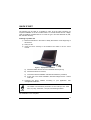
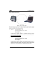
The following can be used as a checklist to verify all of the steps necessary for
complete installation of the DL Cordless Card™ for a DOS terminal and for a laptop
(with two PCMCIA overlaid slots for PC cards of type II and with Windows 98, ME,
XP, and later versions).
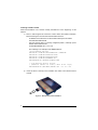
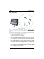
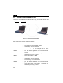
Installing to portable PC
1)
Read all information in the section "Safety Precautions" at the beginning of
this manual.
2)
Start your PC.
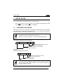
3)
Insert the DLCC correctly in the PCMCIA slot. Refer to the PC user's
manual.
Figure 1 - Laptop Card Installation
A)
Windows notifies the PC has a new hardware device (DLCC);
B)
Windows searches for a driver;
C) Insert the enclosed installation CD-ROM and follow the procedure;
D) At the end of the driver installation, Windows assigns DLCC a virtual
COM port.
4)
Configure the DLCC address according to your application. See
"Configuration Methods".
The default communication parameters of the COM port are: 9600
baud, no parity, 8 data bits, 1 stop bit, handshaking disabled
NOTE
The installation is now complete.
ix
Installing to DOS Terminal
Read all information in the section "Safety Precautions" at the beginning of this
manual.
1)
Rhino™ will recognize the card if the correct drivers are loaded. Therefore,
before inserting the card into the terminal make sure that:
-
in NEWCFG.SYS the driver for the PCMCIA serial ports is loaded:
A:\PCMCIA\PCMSCD.EXE
-
the scan engine driver is correctly configured (COM 3, interrupt 5) and
loaded after PCMSCD.EXE:
A:\DRIVERS\REDIR.SYS -c3 -i5 -b3
The following is an example of the NEWCFG.SYS:
;Load PCMCIA drivers
DEVICE=A:\PCMCIA\CNFIGNAM.EXE /DEFAULT
DEVICE=A:\PCMCIA\PCMSSC40.EXE
DEVICE=A:\PCMCIA\PCMCSFUL.EXE
DEVICE=A:\PCMCIA\PCMRMAN.SYS
DEVICEHIGH=A:\PCMCIA\PCMSCD.EXE
; Scan Engine Device Driver
; (Emulate SE1200 on Com3 @ 9600 N-8-1 Irq5)
DEVICEHIGH=A:\DRIVERS\REDIR.SYS -c3 -i5 -b3
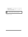
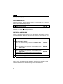
2)
Insert the DLCC correctly in the PCMCIA slot. Refer to the terminal user's
manual.
Figure 2 - DOS Terminal Card Installation
x
3)
Start the DOS terminal. The system assigns DLCC a virtual COM port
(COM 3, interrupt 5).
4)
Configure the DLCC address according to your application. See
"Configuration Methods" paragraph.
The default communication parameters of the COM port are: 9600
baud, no parity, 8 data bits, 1 stop bit, handshaking disabled
NOTE
The installation is now complete.
xi
CONFIGURATION METHODS
DLCC configuration can be performed by four methods:
•
DL Mobile Configurator™ to set the primary DLCC parameters;
•
DL Sm@rtSet™ software configuration program;
•
configuration strings sent from the Host via COM port;
•
DLCARD.EXE DOS
configuration of DLCC.
Configuration
Program
to
perform
a
complete
Your card is supplied with its own Quick Reference Manual which provides basic
application parameter settings using configuration strings, default values, and
specific technical features. You can see either your card's Quick Reference Manual
or this manual for initial configuration.
To use this manual for initial setup see chapter 2.
If you need to change the default settings for your specific application, see chapter 3
and the Examples in appendix A.
DL Mobile Configurator™
Through this Windows-based utility program it is possible to configure the terminal
and set the primary DLCC parameters from a PC. To send the configuration to the
terminal connect the PC to Rhino™ via RS232. For more details about this
configuration method refer to the DL Mobile Configurator™ manual.
DL Sm@rtSet™
DL Sm@rtSet™ program, available on the Datalogic website, is a Windows-based
utility program providing a quick and user-friendly configuration method.
It allows defining the complete DLCC configuration and sending it directly to the card
via virtual COM port.
Connect to www.datalogic.com/services/support/ to download the software.
Configuration Strings from Host
This configuration method may be used for initial and complete configuration (see
chapter 2) by sending the desired strings provided in chapter 3 through the COM
port. Batch files containing the desired parameter settings can be prepared to
configure the card quickly and easily.
Reference notes describing the operation of more complex parameters are given in
chapter 4.
xii
DLCARD.EXE DOS Configuration Program
This configuration method allows setting DLCC through a vehicle mounted terminal
running the DOS operating system.
Upon start, the DOS DLCARD.EXE program checks communication with DLCC. If
the test is successful, the program will open the file DLCARD.INI that includes a list
of keywords. The keywords accepted are the following:
•
•
•
•
RESET_CFG, to reset card configuration to default (possible values: TRUE or
FALSE)
ADDRESS, to set the DLCC address (range 0 to 1999)
TERMINATOR, to set the terminator (possible values: CR, CR+LF or NONE)
CMD, to send any command configuration string
Here is an example of DLCARD.INI file:
____________________________________________________________
[main]
reset_cfg = TRUE
address = 1973
terminator = cr
[commands]
;set minimum destination address
cmd = $+MS1234$;set maximum destination address
cmd = $+MT1235$____________________________________________________________
The DLCC will be set consequently.
In the DOS command line, if you launch the DLCARD.EXE program with the
parameter /?, the list of all the possible parameters will be shown.
Example: C:\ DLCARD /?
xiii
xiv
INTRODUCTION
1
1
INTRODUCTION
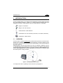
The DL Cordless Card™ is a PCMCIA card developed to provide wireless 433 MHz
RF communication between a laptop or a vehicle mounted terminal (Host) and
Datalogic RF devices or base stations, which are STAR-System™ compatible:
-
Gryphon™ M Readers
-
Dragon™ M Laser Scanners
-
STAR Modem™ Radio Modems
-
Formula Basic Line RF Terminals (F734-E/RF, F725-E/RF, F660-E/RF)
-
STARGATE™ Base Stations
1.1
OVERVIEW
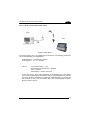
DLCC provides a wireless bi-directional communication between the Host and the RF
devices. DLCC installed in a vehicle mounted terminal is a Server (receiver) to the
RF Devices and also a Client (transmitter) to STAR Modem, which receives data for
the printer (Figure 3).
STAR-System™ uses the Narrow Band RF radio and Datalogic CSMA/CA protocol
to automatically link and manage all the RF devices in the system. This protocol
manages the data transmission using a 16-bit CRC checksum. All RF devices in the
system must implement the CSMA/CA protocol and therefore be configured using
the STAR-System™ setup procedure.
Figure 3 – Bi-directional communication.
To configure the card for operating in this mode refer to paragraph 2.2.
1
DL CORDLESS CARD
1
1.2
LED INDICATOR
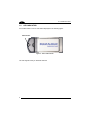
DL Cordless Card™ has one red LED as displayed in the following figure:
LED Indicator
Figure 4 - DLCC LED Indicator
The LED signals activity on PCMCIA interface.
2
INITIAL SETUP
2
2
INITIAL SETUP
For a correct DLCC configuration keep in mind the following:
•
when using the DLCC for the first time, set the desired card address via COM
Port, since its factory default address is "Undefined";
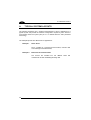
2.1
CONFIGURATION STRINGS
When using a DLCC on a terminal or a portable PC, initial setup can be performed
via COM port by sending the configuration strings to the card using any terminal
emulation program, for example Hyper Terminal.
Ensure that your PC COM port is set as follows:
9600 baud, no parity, 8 data bits, 1 stop bit, handshaking disabled.
NOTE
The programming sequence is the following:
$+
Command
$-
CR
Carriage return character (0D Hex.)
Exit and Save configuration
Character sequence in following tables
Enter configuration environment
Example
Command programming sequence:
$+
RC1237
$-
CR
Carriage return character (0D Hex.)
Exit and Save configuration
DLCC address: 1237
Enter configuration environment
NOTE
If you sent a wrong configuration string, you have to wait for a period
of time equal to Rx timeout (default: 5 sec.) before sending the
following configuration string.
3
DL CORDLESS CARD™
2
2.2
DLCC SETUP
RESTORE DEFAULT
Whenever necessary, send the following string to DLCC via COM Port to restore its
default values. Otherwise skip to step 2:
1.
Restore DLCC Default
$+$*CR
This command does not change the DLCC address nor the destination device
addresses, nor the RF Baud Rate parameters.
SET RADIO ADDRESSES
Follow the procedure below to set the DLCC radio address and prepare it to receive
and transmit data to all devices included in the range from the First to the Last
destination device.
2.
Enter Configuration
3.
Set DLCC Radio Address
xxxx = four digits for the DLCC address (from 0000 to 1999).
This address must be unique.
RCxxxx
4.
First Destination Device Address
xxxx = four digits for the Destination Device address (from
0000 to 1999).
MSxxxx
5.
Last Destination Device Address
xxxx = four digits for the Destination Device address (from
0000 to 1999).
If transmitting to one Destination device only, this selection
is not required.
MTxxxx
6.
Exit and Save Configuration
$+
$-CR
Step 4 and 5 can be omitted when the card is used only to receive data (Server).
When a range of cable-connected destination devices (i.e. a Stargate™ RS485
network) is defined, DLCC activates roaming towards all these devices.
4
CONFIGURATION
3
3
CONFIGURATION
Once the card is setup, you can change the default parameters to meet your
application needs by sending the desired strings to the card via COM Port.
The following table lists all configuration commands which do not require the $character:
Description
String
Enter Configuration
$+
Exit and Save Configuration
$-
Restore Default
$+$*CR
Transmit Software Release
$+$!CR
Transmit Configuration
$+$&CR
In this manual, the configuration parameters are divided into logical groups making it
easy to find the desired function based on its reference group.
The configuration parameter groups are the following:
COM parameters allow the configuration of the COM port.
DATA FORMAT parameters regard the messages sent and received via COM port.
RADIO PARAMETERS allow configuration of radio protocol parameters.
NOTE
It is strongly recommended to read par. 4.1 in Radio and Serial
Communication controls and the example applications in appendix A
for correct parameter settings.
5
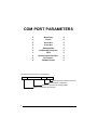
COM PORT PARAMETERS
BAUD RATE
PARITY
DATA BITS
STOP BITS
HANDSHAKING
ACK/NACK PROTOCOL
FIFO
INTER-CHARACTER DELAY
RX TIMEOUT
FRAME PACKING
The programming sequence is the following:
$+
Command
$-
CR
Carriage return character (0D Hex.)
Exit and Save configuration
Character sequence in following tables
Enter configuration environment
6
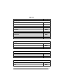
COM PORT
Description
String
BAUD RATE
150 baud
CD0
300 baud
CD1
600 baud
CD2
1200 baud
CD3
2400 baud
CD4
4800 baud
CD5
9600 baud
CD6
19200 baud
CD7
38400 baud
CD8
57600 baud
CD9
PARITY
None
CC0
Even parity
CC1
Odd parity
CC2
DATA BITS
7 bits
CA0
8 bits
CA1
9 bits
CA2
STOP BITS
1 bit
CB0
2 bits
CB1
7
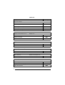
COM PORT
Description
HANDSHAKING
String
see par. 4.2.1
Disable
CE0
Hardware (RTS/CTS)
CE1
Software (XON/XOFF)
CE2
RTS always ON
CE3
Modem (RTS/CTS)
CE4
ACK/NACK PROTOCOL
see par. 4.2.2
Disabled
ER0
Enable ACK/NACK
ER1
Enable DATA/NACK
ER2
FIFO
see par. 4.2.4
Disable
ME1
Enable
ME0
INTER-CHARACTER DELAY
CK00 – CK99
Inter-character delay (ms)
RX TIMEOUT
see par. 4.2.3 and par. 4.2.5
CL00 – CL99
RX Timeout (sec)
FRAME PACKING
see par. 4.2.5
Frame + [CR]
ML0
[STX] + Len + frame + [CR]
ML1
Frame after timeout
ML2
8
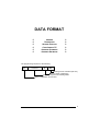
DATA FORMAT
HEADER
TERMINATOR
HEADER POSITION
CODE LENGTH TX
ADDRESS STAMPING
ADDRESS DELIMITER
The programming sequence is the following:
$+
Command
$-
CR
Carriage return character (0D Hex.)
Exit and Save configuration
Character sequence in following tables
Enter configuration environment
9
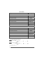
DATA FORMAT
Description
String
HEADER
EA00
No header
One character header
EA01x
Two character headers
EA02xx
Three character headers
EA03xxx
Four character headers
EA04xxxx
Five character headers
EA05xxxxx
Six character headers
EA06xxxxxx
Seven character headers
EA07xxxxxxx
Eight character headers
EA08xxxxxxxx
TERMINATOR
EA10
No terminator
One character terminator
EA11x
Two character terminators
EA12xx
Three character terminators
EA13xxx
Four character terminators
EA14xxxx
Five character terminators
EA15xxxxx
Six character terminators
EA16xxxxxx
Seven character terminators
EA17xxxxxxx
Eight character terminators
EA18xxxxxxxx
x=
HEX values representing an ASCII character.
x = HEX value from 00 to FE in Appendix B.
Example: Header = AB
Two character header
EA02
A
+
41
B
+
42
Example: Terminator = CR LF
Two character terminator
EA12
For more details see par. 4.3.1.
10
CR
+
0D
LF
+
0A
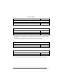
DATA FORMAT
Description
HEADER POSITION
String
see par. 4.3.1
First frame field
ES0
Before message field
ES1
CODE LENGTH TX
Code length not transmitted
EE0
Code length transmitted in variable-digit length
EE1
Code length transmitted in fixed 4-digit format
EE2
The code length is transmitted in the message after the Headers and Code Identifier
characters.
The code length is calculated after performing any field adjustment operations.
ADDRESS STAMPING
see par. 4.3.2
Disable
RU0
Enable
RU1
ADDRESS DELIMITER
see par. 4.3.3
Disable
RV0
Enable
RV1a
a = a Hex value representing the ASCII character in the range from 00 to FE in Appendix B.
11
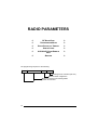
RADIO PARAMETERS
RF BAUD RATE
TRANSMISSION MODE
RADIO PROTOCOL TIMEOUT
SINGLE STORE
ACK/NACK FROM REMOTE
HOST
BEACON
The programming sequence is the following:
$+
Command
$-
CR
Carriage return character (0D Hex.)
Exit and Save configuration
Character sequence in following tables
Enter configuration environment
12
RADIO PARAMETERS
Description
RF BAUD RATE
String
see par. 4.4.1
9600 baud
MF0
19200 baud
MF1
TRANSMISSION MODE (Client only)
see par. 4.4.2
1 way mode
MW0
2 way mode
MW1
RADIO PROTOCOL TIMEOUT (Client only)
see par. 4.4.3
MH01 – MH19
Radio protocol timeout (seconds)
SINGLE STORE (Client only)
see par. 4.4.4
Disable
MO0
One attempt
MO1
Two attempts
MO2
Three attempts
MO3
Four attempts
MO4
Five attempts
MO5
Six attempts
MO6
Seven attempts
MO7
Eight attempts
MO8
Continuous
MO9
13
RADIO PARAMETERS
Description
String
ACK/NACK FROM REMOTE HOST (Client only)
see par. 4.4.5
Disabled
MR0
Enable ACK/DATA/NACK
MR1
BEACON (Client only)
see par. 4.4.6
Disabled
MB0
Beacon every 2 seconds
MB1
Beacon every 3 seconds
MB2
Beacon every 4 seconds
MB3
Beacon every 5 seconds
MB4
Beacon every 6 seconds
MB5
Beacon every 8 seconds
MB6
Beacon every 10 seconds
MB7
Beacon every 20 seconds
MB8
Beacon every 30 seconds
MB9
14
PARAMETER ISSUES AND DEFINITIONS
4
4
PARAMETER ISSUES AND DEFINITIONS
4.1
RADIO AND SERIAL COMMUNICATION CONTROLS
DLCC communication can be controlled by several parameters depending on
whether it is a Client or Server. DLCC can act as both Client and Server.
The following table summarizes which parameters are controlled by the Client and
which ones are controlled by the Server.
Client (Transmitter)
controlled parameters:
Transmission Mode
ACK/NACK From Remote Host
FIFO
Handshaking
Single Store
NOTE
Server (Receiver)
controlled parameters
ACK/NACK Protocol
Handshaking
To avoid incorrect interpretation of ACK characters, ACK/NACK
Protocol and ACK/NACK From Remote Host cannot be
simultaneously enabled on the same DLCC.
To help understand the various communication control possibilities among the
different communication modes, we will analyze the communication control
parameter settings for the following 3 cases:
1) DLCC acting as Server
2) DLCC acting as Client (like an RF device)
3) DLCC as client / server
15
DL CORDLESS CARD™
4
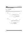
Case 1 – DLCC as Server
DRAGON 1
HOST
DRAGON 2
DRAGON 3
DLCC
F734-E
Figure 5 –DLCC as Server
DLCC as a Server receives data from RF devices. The ACK/NACK Protocol
parameter can be set to assure correct communication between DLCC and the local
Host.
Assuming the RF devices are setup for 2 way transmission in STAR-System™ mode
we can analyze the following ACK/NACK protocol selections:
RF devices - Transmission Mode = 2 ways
The Host must respond to a 2 way transmission
•
If DLCC - ACK/NACK = disabled
there is no control of the communication between DLCC and the Local Host.
DLCC answers the RF device which initiated the 2 way transaction with DATA
received from the Local Host.
•
If DLCC - ACK/NACK = enabled
when the Local Host receives a message correctly, it answers DLCC with the
ACK character. Only then does DLCC acknowledge the RF device which
initiated the 2 way transaction with an Empty Answer.
•
DLCC - DATA/NACK = enabled
when the Local Host receives a message correctly, it answers DLCC with DATA.
DLCC then answers the RF device which initiated the 2 way transaction with this
DATA (i.e. command to RF device display).
16
PARAMETER ISSUES AND DEFINITIONS
4
Case 2 – DLCC as Client (like an RF device)
HOST
Client
Figure 6 - DLCC Client
In the figure above, DLCC is a Client (as an RF device). The following parameters
may be set depending on the application:
STAR Modem™ - ACK/NACK = enabled
STAR-System™ - Rx / Tx = enabled
•
If DLCC -
Transmission Mode = 1 way
ACK/NACK from Remote Host = disabled
FIFO = disabled
Handshaking = modem (RTS/CTS)
In this case, DLCC sends data (messages) to the Remote Host. The special
case of FIFO disabled blocks transmission until an acknowledgement is received
from Host. Because ACK/NACK is enabled for STAR Modem™, only after this
has received an ACK from the Remote Host does it acknowledge reception
(Empty Answer to DLCC).
17
DL CORDLESS CARD™
4
Case 3 – DLCC as Client / Server
Client
Server
HOST 1
HOST 2
Figure 7 – DLCC as Client / Server
Both DLCCs are able to communicate bi-directionally. For analysis purposes only, we
assume the situation where Host 1 is Client and Host 2 is Server. It is clear that the
situation is analogous in the opposite direction:
•
If DLCC 1 -
Transmission Mode = 1 way
ACK/NACK from Remote Host = disabled
FIFO = enabled
Handshaking = any
The Client, (Host 1) sends a message to the Remote Host (Host 2), but no
control exists upon reception and even if ACK/NACK Protocol is implemented on
the Server side (Remote Host), no answer is returned from DLCC 2 to DLCC 1.
This is not a secure communication.
•
If DLCC 1 -
Transmission Mode = 1 way
ACK/NACK from Remote Host = enabled
FIFO = enabled
Handshaking = any
The Client, (Host 1) sends a message to the Remote Host (Host 2). DLCC 2
acknowledges good radio reception but no control is made on Remote Host
reception. If DLCC 2 acknowledges radio reception within the Radio Protocol
Timeout, DLCC 1 sends ACK to its local Host, otherwise it sends NACK.
18
PARAMETER ISSUES AND DEFINITIONS
•
If DLCC 1 -
4
Transmission Mode = 2 ways
ACK/NACK from Remote Host = enabled
FIFO = enabled
Handshaking = any
Single Store = enabled
The Client, (Host 1) sends a message to the Remote Host (Host 2) and expects
an answer from Host 2. Host 2 answers with DATA (a string of up to 238
characters). If DLCC 2 sends this DATA answer within the Radio Protocol
Timeout, DLCC 1 sends it to its local Host (Host 1), otherwise DLCC 1 sends
NACK. In addition, the Single Store parameter upon Radio Protocol timeout,
causes DLCC 1 to retry transmission of the same message the defined number
of times, before responding to its local Host (Host 1) with NACK.
Host 1 -
•
Handshaking = RTS/CTS
If DLCC 1 -
Transmission Mode = any
ACK/NACK from Remote Host = enabled
FIFO = disabled
Handshaking = modem (RTS/CTS)
The Client, (Host 1) sends a message to the Remote Host (Host 2). DLCC 1
after receiving the message, blocks transmission of Host 1 until communication
is completed according to the other communication control parameter settings as
described above.
NOTE
The most secure settings for bi-directional communication is to have
ACK/NACK from Remote Host enabled and Two-way transmission at
both ends. In addition, in case the first transmission fails, the Single
Store parameter automatically repeats transmission of the same data
packet up to the number of specified attempts.
19
DL CORDLESS CARD™
4
4.2
4.2.1
COM PORT PARAMETERS
Handshaking
Modem: (RTS/CTS)
DLCC deactivates the RTS line when it cannot receive a character from the Host.
DLCC can transmit data only if the CTS line (controlled by the Host) is active.
Signals at
EIA levels
DLCC™ Side
Host Side
RX
Received data
RTS
Received data
Modem busy
Signals at
EIA levels
DLCC™ Side
Host Side
TX
Transmitted data
CTS
Transmitted data
Host busy
Modem RTS/CTS Handshaking
20
PARAMETER ISSUES AND DEFINITIONS
4
Hardware handshaking: (RTS/CTS)
The RTS line is activated by DLCC before transmitting a character. Transmission is
possible only if the CTS line (controlled by the Host) is active.
Signals at
EIA levels
RTS
TX
Transmitted data
Transmitted data
Host busy
CTS
Hardware RTS/CTS Handshaking
Software handshaking: (XON/XOFF)
During transmission, if the Host sends the XOFF character (13 Hex), the card
interrupts the transmission with a maximum delay of one character and only resumes
when the XON character (11 Hex) is received.
Transmitted data
Transmitted data
TX
RX
XOFF
Host busy
XON
Host ready
Software XON/XOFF Handshaking
21
DL CORDLESS CARD™
4
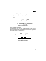
4.2.2
ACK/NACK Protocol
This parameter sets a transmission protocol which takes place between DLCC
(Server) and an RF device. An RF device (such as a hand-held reader) passes its
data (code read) to the card installed into the terminal. The Host sends an ACK
character (06 HEX) to the card in the case of good reception; a NACK character (15
HEX) requesting re-transmission is sent to the card in case of bad reception.
In the particular case where the RF device is configured for 2 way transmission and
therefore requires an answer, it is advised to set DLCC with the DATA/NACK
protocol. The DATA answer from the Local Host is implicitly considered an ACK and
is sent to the RF device. If instead ACK/NACK is used, the card generates an Empty
Answer to the RF device.
Before selecting this parameter ensure that “ACK/NACK from
Remote Host” is disabled (see par. 4.4.5).
CAUTION
Data
Server
ACK/NACK Disabled
Data
Server
ACK or NACK
ACK/NACK Enabled
Data
Server
DATA or NACK
DATA/NACK Enabled
22
PARAMETER ISSUES AND DEFINITIONS
4
If the card does not receive an ACK, DATA or NACK, transmission is ended after the
RX Timeout (see par. 4.2.3 ). See also Radio Protocol Timeout, par. 4.4.3, for radio
transmission to RF devices.
For ACK/NACK selection when DLCC as Client, is transmitting to a destination
device connected to a Remote Host, refer to par. 4.1.
4.2.3
RX Timeout
This parameter can be used to automatically end data reception from the Local Host
after the specified period of time.
If no character is received from the Local Host, after the timeout expires, any
incomplete string is flushed from the card buffer.
Refer to par. 4.2.5 for RX Timeout functioning when defining the frame packing.
4.2.4
FIFO
If enabled, the Destination Device collects all messages sent by DLCC and sends
them in the order of acquisition to the connected Remote Host.
If disabled, DLCC blocks the message transmission from the Local Host until an
answer signaling the right/wrong message transmission has been received from the
Destination Device (1 way) or the Remote Host (2 way). Once the answer has been
received, the Local Host is allowed to send a new message.
This command requires the modem (RTS/CTS) handshaking to be enabled.
For more details about the Transmission Mode refer to par. 4.4.2.
23
DL CORDLESS CARD™
4
4.2.5
Frame Packing
This parameter defines the format of the frame to be transmitted between DLCC and
the Host.
The frame received by DLCC may contain a maximum of 238 characters. All
characters not included within this number will be transmitted from the Host in a new
frame.
Frame from Host to DLCC
FRAME
Address
Address Delimiter
MESSAGE
The Address field has different meanings depending on if the FRAME is sent as a 2
way answer to an RF device, or if it is a new message that the DLCC Client sends to
a destination device. See par. 4.3.2 for details.
Frame from DLCC to Host
FRAME
*Header
*Header
**Time-Stamp
Address
Address Delimiter
**Time-Stamp-Del
**Code Id
MESSAGE
Code Len
DATA
Terminator
*
There is only one header whose position can be defined through the related
parameter (see par. 4.3.1).
**
These are optional fields which can be configured depending on the type of RF
device used.
The Address field has different meanings depending on if the FRAME is a 2 way
answer to a previous 2 way transaction initiated by a DLCC Client, or if it is a new
message that an RF device sends to the DLCC Server. See par. 4.3.2 for details.
24
PARAMETER ISSUES AND DEFINITIONS
4
Correct FRAME identification is managed by frame packing. Three different types of
frame packing can be selected:
•
Frame+ [CR] (default): the frame sent to DLCC is terminated by [CR]. This
means you cannot use the [CR] character within the frame.
In Frame + [CR] mode, make sure the FRAME does not contain [CR], nor begin
with $+ or #+ characters.
FRAME
[CR]
The frame transmitted by DLCC has no additional field. In this case the end of
the FRAME is either DATA or Terminator if any.
FRAME
•
[STX]+LEN+Frame+[CR]: both frames sent to and by DLCC are preceded by
[STX], LEN and terminated by [CR], where LEN is a field of 4 digits and indicates
the FRAME length in number of characters, that is FRAME +CR.
[STX]
LEN
FRAME
[CR]
In this mode, it is not necessary to use the Frame Packing to send commands.
(i.e. $+$&[CR]).
The [STX], [CR] and [ESC] characters contained in the frame must be preceded
by the [ESC] character for a correct transmission.
•
Frame after Timeout: if the delay between two consecutive characters is more
than the selected timeout, the card considers the frame completed. The timeout
corresponds to 1/10 of the value defined for RX Timeout (see par. 4.2.3).
Therefore, the timeout for frame packing is calculated in ms (from 10 ms to 990
ms).
NOTE
It is not possible to disable this timeout, therefore possible
values are in the range 10 - 990 ms. If RX Timeout is disabled,
Frame after Timeout is 10 ms.
Both the frames sent to and by DLCC have no additional fields:
FRAME
All commands to be sent using this frame packing must be preceded by the
string below, which substitutes the $+ character:
#+++PROG_REQ+++#
25
DL CORDLESS CARD™
4
This string is always transmitted in a single frame preceding the one containing
the configuration command, as shown in the following examples:
Example 1
Sending the $+$![CR] command to transmit the card software release:
st
1 Frame = #+++PROG_REQ+++#
nd
2 Frame = $![CR]
Example 2
Sending the $+ML0$-[CR] command to set the default frame packing
configuration:
st
1 Frame = #+++PROG_REQ+++#
nd
2 Frame = ML0$-[CR]
4.3
DATA FORMAT
4.3.1
Header/Terminator Selection
The header/terminator selection is not effected by restore default command.
Header Position
This parameter defines the header position within the frame to be transmitted from
DLCC to the Host. The header can be positioned in either the first field of the frame
or in the field preceding the message:
FRAME
HEADER
HEADER
Time-Stamp
Address
Address Delimiter
Time-Stamp-Del
Code Id
MESSAGE
Code Len
DATA
Terminator
The Address field has different meanings depending on if the FRAME is a 2 way
answer to a previous 2 way transaction initiated by a DLCC Client, or if it is a new
message that an RF device sends to the DLCC Server. See par. 4.3.2 for details.
26
PARAMETER ISSUES AND DEFINITIONS
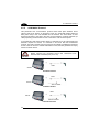
4.3.2
4
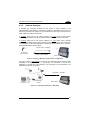
Address Stamping
If enabled, this command includes the RF device or DLCC address in the
message/answer transmitted. It is advised to enable this parameter when DLCC is a
Server for more than one Client in 2 way transmission. In this way the Host knows to
which Client the answer must be sent.
If receiving data from an RF device working in 1 way mode, DLCC (Server)
automatically includes the RF device address in the message to be sent to the Host.
If receiving data from an RF device working in 2 way mode, DLCC (Server)
automatically includes the RF device address in the message to be sent to the Host.
It is required to set the Host application to include the same address in the answer to
be transmitted back to the RF device.
RF Dev. Addr + message
RF Device
in 2 way mode
RF Dev. Addr + answer
DLCC Server
Figure 8 - Receiving a Message from RF device in 2 Way Mode
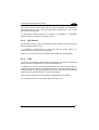
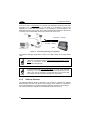
If DLCC as Client, is transmitting to more than one destination device (see the three
Stargates in the figure below) in 1 way mode, it is necessary to set its Host
application to include the card address in the message to be transmitted to the
destination devices of the system.
Card Addr. + message
Destination
Device
DLCC Client
Figure 9 - Transmitting a Message in 1 Way Mode
27
DL CORDLESS CARD™
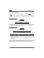
4
If DLCC as Client, is transmitting to more than one destination device (see the three
Stargates in the following figure) in 2 way mode, it is necessary to set its Host
application to include the card address in the message to be transmitted to the
destination devices of the system. DLCC will include the same address in the answer
it receives from the destination devices and sends back to the Host.
Card Addr. + message
Card Addr. + answer
Destination
Device
Client
Figure 10 - Transmitting a Message in 2 Way Mode
The Address Stamping parameters consist of a 4-digit number in the range 00001999.
When the card receives data in 2 way mode from more than one RF
device, it is advised to enable Address Stamping for correct radio
transaction management.
NOTE
NOTE
4.3.3
If communicating with only one RF device in 2 way mode, Address
Stamping is not required, since the data/answer generated by the
Host is only sent to that device. In this case DLCC can receive data
(messages) via radio only after sending the 2 way answer.
Address Delimiter
The Address Delimiter allows a character to be included to separate the Address
stamping fields from the next fields in the message. Once enabled, it is required to
set the Host application to include the Address Delimiter character in the message.
Any character can be included in the hexadecimal range from 00 to FE.
28
PARAMETER ISSUES AND DEFINITIONS
4.4
4
RADIO PARAMETERS
4.4.1
RF Baud Rate
This parameter defines the baud rate used for radio communication. The baud rate
value can be set to 9600 or 19200 according to the device communicating with
DLCC. 19200 is the default value.
4.4.2
Transmission Mode (Client only)
DLCC Client can communicate within the system using two different transmission
modes:
•
1 way mode:
(default)
DLCC transmits data without requiring an acknowledgement
answer from the Remote Host (see par. 4.1 for details).
•
2 way mode:
DLCC transmits data requiring an acknowledgement answer
from the Remote Host (see par. 4.1 and par. 4.4.5 for details.
4.4.3
Radio Protocol Timeout (Client only)
This parameter sets the valid time to wait before radio transmission between DLCC
and a destination device is considered failed.
This parameter should be set taking into consideration the radio traffic (number of
devices in the same area).
If the RS232 interface connecting the Remote Host and the destination device is
used with ACK/NACK enabled, this parameter should be at least equal to the RX
Timeout parameter for low traffic environments. It should be increased if there are
many devices in the same area.
4.4.4
Single Store (Client only)
This command is active when DLCC (Client) transmits messages/data to a
destination device.
It guarantees a secure control to prevent the transmission of duplicated data.
If Single Store is enabled and DLCC does not receive any answer of good
transmission from the destination device, it enters a special operating mode that
stops sending new messages. When such operating mode is entered, the card
retries transmission itself for the number of attempts selected in the configuration.
29
DL CORDLESS CARD™
4
Once the transmission is successful, the card continues to send new messages. If
transmission is not successful after the number of configured attempts, the message
is lost.
To be absolutely sure that messages are received by the destination device, set
Single Store to continuous. A new message will not be sent unless the previous one
is received. If using Single Store as continuous, and the transaction is not received,
check that the Server is active and that the DLCC configuration is correct.
If your application requires an acknowledgement from the Remote PC, you must
define Single Store and enable ACK/NACK From Remote Host (see par. 4.4.5).
4.4.5
ACK/NACK From Remote Host (Client only)
This parameter sets a transmission protocol which takes place between the DLCC
(Client) Host and the destination device Host (Remote Host). The transmission is
influenced by the transmission mode selected (see par. 4.4.2).
Before selecting this parameter ensure that “ACK/NACK Protocol”
is disabled (see par. 4.2.2).
CAUTION
One way mode:
Host sends a message to DLCC which passes it to the destination device via radio.
In case of good transmission, the destination device transmits a radio
acknowledgement back to the card. If received before the Radio Protocol Timeout
expires, DLCC sends an ACK character to the Host. If the timeout expires before
receiving any acknowledgement, the card transmits a NACK character.
Message
radio
acknowledgement
Host
Remote Host
1 Way Transmission Mode
30
PARAMETER ISSUES AND DEFINITIONS
4
Two way mode:
Host sends a message to DLCC which passes it to the destination device via radio.
The destination device transmits the message to the Remote Host which responds
with DATA. This answer is sent to DLCC through the destination device. Then, the
card transmits it to the Host.
If the Radio Protocol Timeout expires before the answer from Remote Host is
received by DLCC or in case the Remote Host does not respond, DLCC sends a
NACK character to the Host.
Message
Remote Host answer
Message
DATA
Host
Remote Host
2 Way Transmission Mode
NOTE
4.4.6
If the Host continues to send new messages before receiving any
answer from the Remote Host, it is strongly suggested to enable the
handshaking on the Host connected to DLCC for a correct
functioning.
Beacon (Client only)
If this parameter is enabled, DLCC polls the server for data at regular intervals
(configurable from 2 to 30 seconds) by sending a character ENQ (ASCII 05) with a 2
way transaction. The server must always respond with data or with an Empty
Answer.
The selection of this parameter does not influence the card normal radio transaction.
This means that it does not modify the transmission of data sent by the Local Host.
31
DL CORDLESS CARD™
5
5
DEFAULT CONFIGURATION
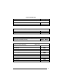
Configuration Parameter
Default Setting
Serial Communication
Baud Rate
Parity, Data Bits, Stop Bits
Handshaking
ACK/NACK Protocol
FIFO
Intercharacter Delay
RX Timeout
Frame Packing
9600
No parity; 8 Data bits; 1 Stop bit
Disabled
Disabled
Enabled
Disabled
5 seconds
Frame +[CR]
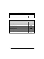
Data Format
Header
Terminator
Header Position
Code Length TX
Address Stamping
Address Delimiter
No headers
[CR] and [LF]
First frame field
Code Length not Transmitted
Disabled
Disabled
Radio Parameters
RF Baud Rate
Transmission Mode
Radio Protocol Timeout
Single Store
ACK/NACK from Remote Host
Beacon
19200 baud
1 way mode
2 sec
Disabled
Disabled
Disabled
32
TECHNICAL FEATURES
6
6
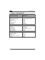
TECHNICAL FEATURES
Electrical Features
Supply voltage
Power consumption
Indicator
5 Vdc ± 3%
400 mW
One red LED
Radio Features
Working frequency
Bit rate
Effective Radiated Power
Range (in open air)
RF Modulation
433.92 Mhz
Up to 19200 baud
<10 mW
15 m / 49.2 ft
FSK
System Configuration
Maximum number of client RF
devices supported by a DLCC
server
32
Environmental Features
Working temperature
Storage temperature
Humidity
Protection class
-20° to +50 °C / -4° to +122 °F
-20° to +70 °C / -4° to +158 °F
90% non condensing
IP30
Mechanical Features
Weight
Dimensions
47 gr
118.25 mm x 54 mm x 9.4 mm
33
DL CORDLESS CARD™
A
A
TYPICAL SYSTEM LAYOUTS
The following examples give a graphical representation of DLCC applications in 2
typical layouts and provide the software configuration required by each device to
communicate within the system (see par. 4.1 for details about the main parameter
functioning).
The examples provide two different DLCC applications:
-
Example 1
DLCC Server
DLCC, installed in a vehicle-mounted terminal, receives data
from Datalogic hand-held devices;
-
Example 2:
Bi-Directional Communication
Two DLCCs are installed into two different Hosts and
communicate via radio transmitting/receiving data.
34
TYPICAL SYSTEM LAYOUTS
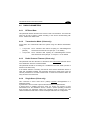
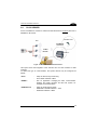
A.1
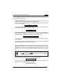
A
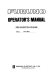
DLCC SERVER
DLCC is installed into a Rhino™ vehicle mounted terminal and receives data from a
DRAGON™ M scanner.
DRAGON™ M
A.P.
433 MHz RF
Connection
2.4 GHz
Network
Wired
LAN
RHINO™
DLCC
Figure 11 - DLCC Server Installed into Rhino™
This layout shows the integration of the 433 MHz and 2.4 GHz networks for data
collection.
To define this type of communication, the system devices may be configured as
follows:
DLCC
-
Setup for Server Only Functioning
DLCC Radio Address = 0017
RHINO™
-
Run an application managing the data communication
between the mobile computer and the host system, for
example Terminal Emulation.
DRAGON™ M
-
Setup for STAR-System mode
DRAGON™ M Radio Address = 1235
Destination Address = 0017
35
DL CORDLESS CARD™
A
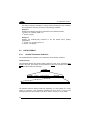
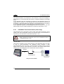
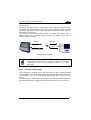
A.2
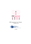
BI-DIRECTIONAL COMMUNICATION
Two DLCCs are installed into the dedicated Host. They communicate with each other
by transmitting and receiving data.
HOST 1
HOST 2
Card 1
Card 2
Figure 12 – Bi-directional Communication
Each system device may be configured as follows:
DLCC 1
-
HOST 1
-
DLCC 2
-
HOST 2
-
36
DLCC Radio Address = 0325
First Destination Device Address = 0263
Handshaking = modem (RTS/CTS)
Frame Packing = frame after timeout (selection advised
for this example for a faster
transmission)
Run the desired application or a terminal emulation
program.
Adjust the Host communication parameters and
handshaking according to DLCC 1.
DLCC Radio Address = 0263
First Destination Device Address = 0325
Handshaking = modem (RTS/CTS)
Frame Packing = frame after timeout
Run the desired application or a terminal emulation
program.
Adjust the Host communication parameters and
handshaking according to DLCC 2.
HEX AND NUMERIC TABLE
B
B
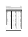
HEX AND NUMERIC TABLE
CHARACTER TO HEX CONVERSION TABLE
char
hex
char
hex
char
hex
NUL
SOH
STX
ETX
EOT
ENQ
ACK
BEL
BS
HT
LF
VT
FF
CR
SO
SI
DLE
DC1
DC2
DC3
DC4
NAK
SYN
ETB
CAN
EM
SUB
ESC
FS
GS
RS
US
SPACE
!
"
#
$
%
&
'
(
)
00
01
02
03
04
05
06
07
08
09
0A
0B
0C
0D
0E
0F
10
11
12
13
14
15
16
17
18
19
1A
1B
1C
1D
1E
1F
20
21
22
23
24
25
26
27
28
29
*
+
,
.
/
0
1
2
3
4
5
6
7
8
9
:
;
<
=
>
?
@
A
B
C
D
E
F
G
H
I
J
K
L
M
N
O
P
Q
R
S
T
2A
2B
2C
2D
2E
2F
30
31
32
33
34
35
36
37
38
39
3A
3B
3C
3D
3E
3F
40
41
42
43
44
45
46
47
48
49
4A
4B
4C
4D
4E
4F
50
51
52
53
54
U
V
W
X
Y
Z
[
\
]
^
_
`
a
b
c
d
e
f
g
h
i
j
k
l
m
n
o
p
q
r
s
t
u
v
w
x
y
z
{
|
}
~
DEL
55
56
57
58
59
5A
5B
5C
5D
5E
5F
60
61
62
63
64
65
66
67
68
69
6A
6B
6C
6D
6E
6F
70
71
72
73
74
75
76
77
78
79
7A
7B
7C
7D
7E
7F
37
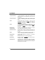
GLOSSARY
1 way transmission
a radio transmission in which DLCC transmits data
without requiring an acknowledgement answer from the
remote Host.
2 way transmission
a radio transmission in which DLCC transmits data
requiring an acknowledgement answer from the remote
Host.
Client
a radio device which can initiate a 1 way or 2 way
transmission to a Server. The Client is also defined as
Transmitter. DLCC, RF terminals or RF hand-held
readers function as Clients.
Server
a radio device which is continuously waiting for a 1 way
or 2 way transmission initiated by a Client. The Server is
also defined as Receiver. DLCC or Stargates™ function
as Servers.
Bi-directional
Communication
the ability to both receive radio messages as a Server
and to initiate radio transmission as a Client.
Destination Device
the radio device to which a message must be sent or to
which an answer to a previously received message must
be given.
DATA
a string of up to 238 characters sent by a client to a
server, or received by a client as a 2 way response.
Empty Answer
a radio acknowledgement containing no information
(data) content.
Local Host
the Host to which DLCC is physically inserted in.
Remote Host
the Host to which a transmitting DLCC Client sends a
message via radio.
STAR-System™
a Datalogic radio communication system that uses a
Narrow Band RF radio and Datalogic proprietary
CSMA/CA protocol to automatically link and manage all
the RF devices in the system.
38
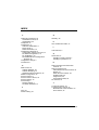
INDEX
C
COM Port Parameters; 20
ACK/NACK Protocol; 22
Handshaking; 20
Compliance; vi
Configuration; 5
COM Port Parameters; 6
Data Format; 9
Radio Parameters; 12
Configuration Methods; xii
Configuration Strings from Host; xii
DL Mobile Configurator™; xii
DL Sm@rtSet™; xii
DLCARD.EXE DOS Configuration
Program; xiii
Configuration Strings; 3
Conventions; v
D
Data Format; 26
Address Delimiter; 28
Address Stamping; 27
Header/Terminator Selection; 26
Default Configuration; 32
DLCC as Client; 17
DLCC as Client / Server; 18
DLCC as Server; 16
DLCC Setup; 4
Restore Default; 4
Set Radio Addresses; 4
F
FIFO; 23
Frame Packing; 24
G
Glossary; 38
H
Hex and Numeric Table; 37
L
LED Indicator; 2
Q
Quick Start; ix
Installing to DOS Terminal; x
Installing to portable PC; ix
R
Radio and Serial Communication
Controls; 15
Radio Parameters; 29
ACK/NACK From Remote Host; 30
Beacon; 31
Radio Protocol Timeout; 29
RF Baud Rate; 29
Single Store; 29
Transmission Mode; 29
RX Timeout; 23
T
Technical Features; 33
Typical System Layouts; 34
Bi-Directional Communication; 36
DLCC Server; 35
39
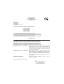
Datalogic Mobile S.r.l.
Via S. Vitalino 13
40012 - Lippo di Calderara
Bologna - Italy
07
dichiara che
declares that the
déclare que le
bescheinigt, daß das Gerät
declare que el
DL Cordless Card EU, Radio Modem with PCMCIA Interface
e tutti i suoi modelli
and all its models
et tous ses modèles
und seine modelle
y todos sus modelos
sono conformi alla Direttiva del Consiglio Europeo sottoelencata:
are in conformity with the requirements of the European Council Directive listed below:
sont conformes aux spécifications de la Directive de l'Union Européenne ci-dessous:
der nachstehenden angeführten Direktive des Europäischen Rats:
cumple con los requisitos de la Directiva del Consejo Europeo, según la lista siguiente:
1999/5/EEC R&TTE
Questa dichiarazione è basata sulla conformità dei prodotti alle norme seguenti:
This declaration is based upon compliance of the products to the following standards:
Cette déclaration repose sur la conformité des produits aux normes suivantes:
Diese Erklärung basiert darauf, daß das Produkt den folgenden Normen entspricht:
Esta declaración se basa en el cumplimiento de los productos con las siguientes normas:
ETSI EN 301 489-3 v 1.4.1, AUGUST 2002:
ELECTROMAGNETIC COMPATIBILITY AND RADIO SPECTRUM MATTERS
(ERM); ELECTROMAGNETIC COMPATIBILITY (EMC) STANDARD FOR
RADIO EQUIPMENT AND SERVICES; PART 3: SPECIFIC CONDITIONS
FOR SHORT-RANGE DEVICES (SRD) OPERATING ON FREQUENCIES
BETWEEN 9 KHZ AND 40 GHZ.
ETSI EN 300 220 v 1.1.1, SEPTEMBER 2004:
ELECTROMAGNETIC COMPATIBILITY AND RADIO SPECTRUM MATTERS
(ERM); SHORT-RANGE DEVICES (SRD); RADIO EQUIPMENT TO BE
USED IN THE 25 MHZ TO 1000 MHZ FREQUENCY RANGE WITH
POWER LEVELS RANGING UP TO 500 MW; PART 3: HARMONIZED EN
COVERING ESSENTIAL REQUIREMENTS UNDER ARTICLE 3.2 OF THE
R&TTE DIRECTIVE
EN 60950-1, DECEMBER 2001:
INFORMATION TECHNOLOGY
GENERAL REQUIREMENTS.
EQUIPMENT
– SAFETY – PART 1:
Lippo di Calderara, September 3rd, 2007
Paola Chientaroli
Quality Assurance Manager
DL Cordless Card TM
www.mobile.datalogic.com
World wide Sales Network
available from: www.mobile.datalogic.com/contacts
Datalogic Mobile S.r.l.
Via S. Vitalino, 13
40012 Lippo di Calderara di Reno
Bologna - Italy
Telephone: (+39) 051-3147011
Fax: (+39) 051-3147561
Reference Manual
©2002-2007 Datalogic Mobile S.r.l.
03/09/2007
09/07