1
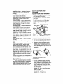
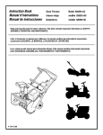
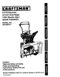
12.5 Horsepower
33 Inch Dual Stage
120V. Electric Start
SNOW THROWER
MODEL NO.
536.881230
Caution:
Read and follow all Safety
Rules and Operating
Instructions before first use
of this product.
SEARS, ROEBUCK
F-O01059J
07/23/99
AND CO., Hoffman Estates, IL 60179 U.S.A.
Table of Contents
Warranty
Safety Rules
Contents of Shipping Carton
Assembly
Operation
Maintenance
LIMITED
TWO-YEAR
2
2
2-4
4-5
5-8
9-14
15-17
WARRANTY
Service and Adjustments
Storage
Troubleshooting
Snow Thrower Repair Parts
Engine Repair Parts
Spanish(EspaSol)
Parts Ordering/Service
Back
ON CRAFTSMAN
SNOW
18-22
23
24
25-36
37-41
42-67
Cover
THROWER
For two years from the date of purchase, when this Craftsman Snow Thrower is maintained, lubricated, and tuned up according to the operating and maintenance instructions in the owner's manual, Craftsman will repair, free of charge, any defect in material or workmanship,
If this Craftsman Snow Thrower is used for commercial or rental purposes, this warranty applies for only 90 days from the date of purchase,
This warranty does not cover the following:
• Items which become worn during normal use, such as spark plugs, drive belts and
shear pins,
• Repairs necessary because of operator abuse or negligence, including bent crank
shafts and the failure to maintain the equipment according to the instructions contained in the owner's manual.
WARRANTY SERVICE IS AVAILABLE BY RETURNING THE CRAFTSMAN SNOW
THROWER TO THE NEAREST CRAFTSMAN SERVICE CENTER/DEPARTMENT
IN
THE UNITED STATES. THIS WARRANTY APPLIES ONLY WHILE THIS PRODUCT
IS IN USE IN THE UNITED STATES.
This warranty gives you specific legal rights, and you may also have other rights which
may vary from state to state.
Sears, Roebuck and Co., D817WA, Hoffman Estates, IL 60179
Look
for this symbol
to point
important
safety
precautions.
ATTENTIONH!
Become
alertlllout
Your
safety is
involved.
TRAINING
CAUTION: Always disconnect spark
Z_
plug wire and place wire where it cannot
contact spark plug to prevent accidental
starting when setting-up, transporting,
adjusting or making repairs.
iMPORTANT: Safety standards require
operator presence controls to minimize the
risk of injury. Your snow thrower is
equipped with such controls. Do not attempt
to defeat the function of the operator
_resence control under any circumstances.
_
California
Proposition
65
WARNING:
The
engine exhaust from this product
contains chemicals known to the
State of California to cause cancer
birth defects or other reproductive
harm.
1.
2.
3.
4.
It means--
Read the operator's manual carefulty.
Be thoroughly familiar with the controls
and the proper use of the snow thrower.
Know how to stop the snow thrower and
disengage the controls quickly.
Never allow children to operate the
snow thrower and keep them away
while it is operating. Never allow adults
to operate the snow thrower without
proper instruction. Do not carry passengers.
Keep the area of operation clear of all
persons, particularly small children and
pets.
Exercise caution to avoid slipping or
falling, especially when operating in
reverse.
PREPARATION
1. Thoroughly inspect the area where the
snow thrower is to be used and remove
all doormats, sleds, boards, wires and
other foreign objects.
2.
Disengage all clutches before starting
the engine (motor).
3.
Do not operate the snow thrower
without wearing adequate winter outer
garments. Wear footwear that wiU
improve footing on slippery surfaces.
4.
Handle fuel with care; it is highly
flammable.
(a) Use an approved fuel container.
(b) Never remove fuel tank cap or add
fuel to a running engine or hot
engine.
(c) Fill fuel tank outdoors with extreme
care. Never fill fuel tank indoors.
(d) Replace fuel tank cap securely and
wipe up spilled fuel
(e) Never store fuel or snow thrower
with fuel in the tank inside of a
building where fumes may reach
an open flame or spark.
(f) Check fuel supply before each use,
allowing space for expansion as
the heat of the engine (motor) and/
or sun can cause fuel to expand.
5.
Use extension cords and receptacles
as specified by the manufacturer for all
snow throwers with electric drive
motors or electric starting motors.
6.
Adjust the snow thrower height to clear
gravel or crushed rock surfaces.
7.
Never attempt to make any adjustments
while the engine (motor) is running
(except when specifically recommended by the manufacturer).
8.
Let engine (motor) and snow thrower
adjust to outdoor temperatures before
starting to clear snow.
9. Always wear safety glasses or eye
shields during operation or while
performing an adjustment or repair to
protect eyes from foreign objects that
may be thrown from the snow thrower.
OPERATION
1.
2.
3.
Do not operate this machine if you are
taking drugs or other medication which
can cause drowsiness or affect your
ability to operate this machine.
Do not use this machine if you are
mentally or physically unable to operate
this machine safely.
Do not put hands or feet near or under
rotating parts. Keep clear of the
discharge opening at all times.
4.
5.
6.
7.
8.
9.
10.
11.
12.
13.
14.
15.
16.
I
Exercise extreme caution when operating on or crossing gravel drives, walks,
or roads. Stay alert for hidden hazards
or traffic.
After striking a foreign object, stop the
engine (motor), remove the wire from
the spark plug, disconnect the cord on
electric motors, thoroughly inspect the
snow thrower for any damage, and
repair the damage before restarting and
operating the snow thrower.
If the snow thrower should start to
vibrate abnormally, stop the (motor) and
check immediately for the cause.
Vibration is genera]ly a warning of
trouble.
Stop the engine (motor) whenever you
leave the operating position, before
unclogging the auger/impeller housing or
discharge guide, and when making any
repairs, adjustments, or inspections.
When cleaning, repairing, or inspecting,
make certain the auger/impeller and all
moving parts have stopped. Disconnect
the spark plug wire and keep the wire
away from the plug to prevent accidental
starting.
Take all possible precautions when
leaving the snow thrower unattended.
Disengage the auger/impeller, stop
engine, and remove key.
Do not run the engine indoors, except
when starting the engine and for
transporting the snow thrower in or out
of the buildl"'ng.Open the outside doors;
exhaust fumes are dangerous (containing CARBON MONOXIDE, an ODORLESS and DEADLY GAS).
Do not clear snow across the face of
slopes. Exercise caution when changing
direction on slopes. Do not attempt to
clear steep slopes.
Never operate the snow thrower without
proper guards, plates or other safety
protective devices in place.
Never operate the snow thrower near
glass enclosures, automobiles, window
wells, drep-offs, and the like without
proper adjustment of the snow discharge
angle. Keep children and pets away.
Do not overload the machine capacity by
attempting to clear snow at too fast a
rate.
Never operate the snow thrower at high
transport speeds on slippery surfaces.
Look behind and use care when
backing.
Never direct discharge at bystanders or
allow anyone in front of the snow
thrower.
17. Disengage power to the auger/impeller
when snow thrower is transportedor
not in use.
18. Use only attachments and accessories
approved by the manufacturer of the
snow thrower (such as tire chains,
electric start kits, etc).
19. Never operate the snow thrower
without good visibility or light. Always
be sure of your footing, and keep a firm
hold on the handles. Walk; never run.
MAINTENANCE
AND STORAGE
1. Check shear bolts and other bolts
frequently for proper tightness to be
sure the snow thrower is in safe
working condition.
2.
Never store the snow thrower with fuel
in the fuel tank inside a building where
ignition sources are present such as
hot water and space heaters, clothes
dryers, and the like. Allow the engine
to cool before stodng in any enclosure.
3.
Always refer to operator's manual
instructions for important details if the
snow thrower is to be stored for an
extended pedod.
4.
5.
Maintain or replace safety and instruction labels, as necessary.
Run the snow thrower a few minutes
after throwing snow to prevent freezeup of the auger/impeller.
Z_ WARNING:
This snow thrower is for
use on sidewalks, driveways and other
ground level surfaces.
Caution should be exercised while using on
steep sloping surfaces. DO NOT USE
SNOW THROWER ON SURFACES
ABOVE GROUND LEVEL such as roofs of
residences, garages, porches or other such
structures or buildings.
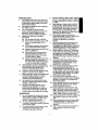
Contents
of Parts Bag
1 - Owner's Manual (not shown)
1 - Parts Bag (not shown)
! - Packet of Fuel Stabilizer (not shown)
Non Assembly parts are found in toolbox
located on top of belt cover.
1 - Warranty Card (not shown)
1-3/8-16 x 2 In. Hex Head Bolt
©
• 2 - Spare Shear Bolts
1 _/8 In.
Flatwasher
©
1 - 3/8 In.
Lockwasher
• 2- Spare Shear Nuts
1- 3/8 In. Hex Nut
@©
1 - Starter Motor Cord
2- Shifter
Knobs
4
2 - 3/8-16 Hex Jam Nuts
Parts packed separately in carton (not shown full size)
2 - Ignition Keys
(Attached to engine in plastic bag)
Z_
CAUTION: Always wear safety
glasses or eye shields while assembling
snow thrower,
TOOLS
REQUIRED
FOR ASSEMBLY
,i
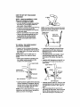
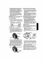
The figure below shows the snow throwe_
completely assembled.
References to the right or teft hand side
of the snow thrower are from the viewpoint
of the operator's position behind the unit,
I
1 - Knife to cut carton and plastic ties
2 - 1/2 inch wrenches (or adjustable
wrenches)
2-
9/16 inch wrenches (or adjustable
wrenches)
1 - Pliers (to spread cotter pin)
1- Screwdriver
Auger Drive Lever
1 - Air pressure gauge
1 - Measuring tape or ruler
The figure below shows the snow thrower in
the shipping carton.
Speed
Lever
Chute
Deflector
Cable
Headlight
Height
Adjust
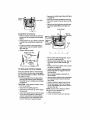
HOW TO SET UP YOUR SNOW
THROWER
"z" fitting
NOTE:
Place fuel stabilizer In a safe
place untll needed for storage.
• Remove top pallet from carton.
• Cut and discard the plastic ties securing
the chute rod to the upper pallet and
place aside. Discard pallet.
• Cut all four comers of the carton from top
to bottom and lay the panels flat.
• Cut the bands holding the snow thrower
to the lower pallet.
• Remove snowthmwer from lower pallet.
• Remove the packing material from the
handle assembly and all protective
material from the unit and discard.
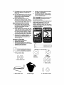
• Cut ties securing the clutch control
cables.
NOTE: If control cables have become unattached from motor mount frame, reconnect
cables as show in figure below.
Tractiondrive
spdng(Iong)
i
I
Auger drive
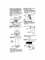
TO INSTALLTHE
UPPER HANDLE
AND CRANKASSEMBLY
• Loosen, but do not remove the screws,
flatwashers, leckwashers and hex nuts in
the upper holes of the lower handle. See
figure below.
NOTE: Make sure the cables are not
caught between the upper and lower
handle.
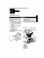
Locate crank assembly removed earlier
and remove the 3/8" nylon Iocknut and
flatwasher from the eye bolt assembly.
See figure below.
Reinstall flatwasher and adapter. Install
eye bolt through lower hole in the left
hand side of the handle. See figure below.
• Raise upper handle into operating position. Upper handle should be to the
outside of the lower handle.
--_t
install the 3/8" flatwasher and the 3/8" nylon Iocknut on the eye bolt as shown in
figure below.
_/" Upper handle
_'_'hexNut
Loosenscrew
3/8" nylon
Locknut
(Do notremove)
I;
_8 Flatwasher
t"
3/8" Lockwasher//_
Eye Bolt
3/8 X 2"Screw
Boot
3/8" Flatwasher
• Install hardware supplied in the parts bag
(Screw, flatwasher, Iockwasher, and he:<
nut) into lower hole on right hand ,side of
handles. Do not tighten until all screws
are in place. See figure above.
NOTE: If the cables have become disconnected from the clutch levers, reinstall the
cables as shown in next figure.
• Carefully remove cotter pin, clevis pin and
universal joint pin from yoke end of crank
rod assembly as shown in first figure on
page 7.
• Place univemal joint into end of worm
gear lining up large holes. Insert universal
joint pin (ensure opening in pin is in line
with small openings in universal joint).
6
• Place yoke end of crank rod around universal joint, lining up openings. Insert
clevis pin through assembly and secure
with cotter pin. Spread ends of cotter pin
to lock in place. See figure below.
• Tighten nut on eye bolt, keeping eye in
line with the rod while tightening the inside
securely.
• Tighten all handle bolts with a 9/16"
wrench.
NOTE: DO NOT cut tie strap located on
chute deflector at this time.
• Push remote chute co n.trgllover into
•Chute Deflector Down '_, position.
• Cut tie strap on chute deflector as shown
_nfigure below.
Tie Strap
Crank Rod
Assembly
Chute
Deflector
Joint
pin
joint
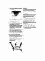
SPEED SELECTOR
ROD
• Cut plastic tie securing shifter [ever
assembly to the shifter bracket. See
figure below.
\
ASSEMBLE
• Remove back cardage bolt, see figure
below.
Bo_tCardagem
• Remove Iocknut, washer, spring and the
bolt. See figure below.
• Tilt chute back into operating position.
See figure below.
Plasticl_ob_
(pointedforward)
operating
Chute
in
position
_._3/8-16
Hex Jam Nut
I_-'-Shifter
Bracket
Control
Panel
Bolt
• Replace carriage bolt.
• Tighten carriage bolt securely. NOTE:
Check all bolts in chute ring for tightness.
• Remove and discard packaging used to
protect chute.
--1/8
tO 3/8
inch of
Exposed
Thread
Position shifter lever assembly as shown
in figure below.
,€
HEADLIGHT
The headlight on your snowthrower is positioned in down position for packaging
purposes. Rotate upwards for operating position.
CHECKLIST
Control Panel
• Reinstall bolt, spring, washer and Iocknut.
See last figure on page 7,
• Tighten Iocknut until 1/8 to 3/16 inch of
the bolt threads protrude past the Iocknut
• Thread the 3/8-16" hex jam nut onto the
lever until the nut roaches the end of the
thread. See last figure on page 7.
• Thread the plastic knob as far as possible
and ensure that the knob points forward.
• Tighten the 3/8-16" hex jam nut against
the knob securely.
• Move shifter through all speeds to ensure
proper tension of the spring. If shifter
lever sticks in any of the notches, loosen
Iocknut 1/2 turn at a time until shifter lever
moves more freely.
REMOTE CHUTE CONTROL
KNOB
• Thread the 3/8-16" hex jam nut onto the
lever until the nut roaches the end of the
thread, See figure below.
• Thread the plastic knob as far as possible
and ensure tha the knob points forward.
• Tighten the 3/8-16" hex jam nut against
the knob securoly.
RemoteChute
Knob
3/8-16
Before you operate your new snow thrower,
to ensure that you receive the best pefformance and satisfaction from this quality
product, please review the following
check|ist:
-J All assembly instructions have been
completed.
_/ The discharge chute rotates freely.
q"
No remaining loose partsin carton.
While learning how to use your snow
thrower, pay extra attention to the following
important items:
_/_ Engine oil is at proper level.
_/4 Make sure gas tank is filled properly
with clean, fresh, unleaded gasoline.
4_/ Become familiar with all controls-their
location and function. Operate controls
before starting engine.
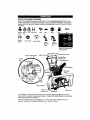
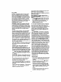
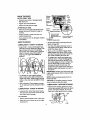
KNOW YOUR SNOW THROWER
READ THIS OWNER'S MANUAL AND SAFETY RULES BEFORE OPERATING YOUR
SNOW THROWER. Compare the illustrations with your SNOW THROWER to familiarize
yourself with the location of various controls and adjustments. Save this manual for future
reference.
Engine Engine
Start
Run
;r_oer
Off
Drive Clutch
Choke On
Fast
Auger Clutch
Slow
Fuel
Stop
Chute
Deflector
Chute
Deflector
Down
Up
Oil
Ignition Key insert to run
pull out to stop
Speed Shifter Lever
Remote Chute
IgniUon
Crank Assembly
Chute
Control
Starter
Handle
Adjust Skids
Bar
Shear Bolt
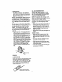
The operation of any snow thrower can result in foreign objects being thrown into the
eyes, which can result in severe eye damage. Always wear safety glasses or eye shields
while operating the snow thrower.
We recommend standard safety glasses or a wide vision safety mask for over your
glasses, available at Craftsman Retail Stores or Service Centers.
Auger Drive Lever - Starts and stops the
auger and impeller (snow gathering and
throwing).
Traction Drive Lever - Propels the snow
thrower forward and in reverse.
Speed Select Lever - Selects the speed of
snow thrower (6 speeds forward and 2
speeds reverse).
Crank Assembly - Changes the direction of
snow throwing through the discharge chute.
Chute Deflector- Changes the distance
the snow is thrown.
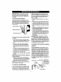
HOWTO USEYOUR
THROWER
TO STOPYOUR
SNOW
SNOWTHROWER
• To stop throwing snow, release the auger
drive lever (see figure below),
• To stop the wheels, release the traction
drive lever,
• To stop the engine, push the throttle control lever to off and pull out (DO NOT
TURN) the ignition key, see figure on
page 9,
Electric Starter Button
Primer button
Discharge Chute - Changes the direction
the snow is thrown.
Choke Control - Used to start a cold enIgnition
gine.
key_
Height Adjust Skids - Adjusts the ground
clearance of the auger housing.
Ignition Key - Must be inserted to start the
engine,
control
Recoil starter
Primer Button - Injects fuel directly into the
Throttle
handle
carburetor manifold for fast starts in cold
weather.
TO CONTROL SNOW DISCHARGE
Recoil Starter Handle - Starts the engine
manually.
• Turn the crank assembly to set the direcThrottle Control - Controls the engine
tion of the snow throwing.
speed.
• Adjust snow chute deflector to set the
Electric Starter Button - Used to start the
distance, Push remote lever forward to
engine using the 120 V. electric starter.
discharge snow down. Pull remote lever
Remote Chute Control Lever- Push forback to discharge snow high and far, See
ward to discharge snow high and far. Pull
figure below.
remote lever back to discharge snow down.
Shear Bolts - Are special bolts that are deknob
signed to break (to protect the
machine) if an object becomes lodged in the
auger housing. Use of a harder bolt will destroy the protection provided by the shear
bolt.
Toolbox - Spare shear pins and spacers are
located in toolbox.
TO MOVE FORWARD AND
BACKWARD
CAUTION:
Read owner's manual
before operating machine. Never direct
discharge toward bystanders. Release the
auger control bar and stop the engine
before unclogging discharge chute or auger
housing and before leaving the machine.
/_
• To shift, release the traction drive lever
and move the speed shifter lever to the
speed you desire. Ground speed is determined by snow conditions. Select the
speed you desire by moving the speed
shifter lever into the appropriate area on
the control panel.
Speeds 1,2 - Wet, Heavy, Extra Deep
Speed 3 - Light
Speed 4 - Very Light
Speeds 5, 6 - Transport only
10
• Engage
the traction
drive lever as shown
in next figure, left hand. As the snow
thrower starts to move, maintain a firm
hold on the handles, and guide the snow
thrower along the cteadng path. Do not
attempt to push the snow thrower.
• To move the snow thrower backward,
move the speed shifter lever into first or
second reverse and engage the traction
drive lever (left hand).
IMPORTANT: Never move the speed shifter
lever while the traction lever is down.
TO THROW SNOW
• Push down the auger drive lever, see figure below, release to stop throwing snow.
TractionDrive Lever
Auger Drive Lever
BEFORE STARTING THE ENGINE
• tf the snow thrower must be moved without the aid of the engine, it is easier to pull
the snow thrower by the handles rather
than pushing.
• Before you service or start the engine, familiarize yourself with the snow thrower.
Be sure you understand the function and
location of all controls.
NOTE: Check tension of clutch cables before starting the engine (See To Adjust The
Control Cables paragraph on page 19).
• Be sure that all fasteners are tight.
• Make sure the height adjust skids are
properly adjusted (See To Adjust Skid
Height paragraph on page 18).
• Checktire pressure (14 to 17 pounds).
See side of tire for maximum inflation. Do
not exceed listed maximum pressure.
CHECKTHE
Left hand
t
/ Righthand
TO USE WHEEL LOCKOUT PIN
• The left hand wheel is secured to the axle
with a klick pin, see figure below. This
unit was shipped with this klick pin in the
locked position (klick pin through hole in
wheel).
OIL
NOTE: The engine was shipped from the
factory filled with oil. Check the level of the
oil. Add oil as needed,
• Make sure the unit is level.
NOTE: Do not check the level of the oil
while the engine runs.
• Remove the oil fill cap/dipstick. Check the
oil.
_Oil Fill/Dipstick
tL
!-Wheel Drive
Locked
__
K'ick Pin/
Position
I_1_1
• For ease of maneuverability in light snow
conditions, disconnect the klick pin from
the wheel locked position and push into
the single wheel drive position (klick pin
through axle hole only), see figure below.
NOTE: Make sure that the klick pin is in the
single wheel drive position, through axle
only and not through the hole in wheel.
Klick Pin_
SingleWheel Drive
;,_,.,'
._)
NOTE: Oil level must be
between full and add
mark.
• If necessary, add oil until the oil reaches
the FULL mark on the oil fill cap/dipstick
(see figure above). Do not add too much
oil.
• Tighten the fill cap/dipstick securely each
time you check the oil level.
NOTE: For extreme cold operating conditions of 0°F and below, use a partial
synthetic 0W30 motor oil for easier starting.
NOTE: S.A.E. 5W30 motor oil may be used
to make starting easier in areas where temperature is consistently 20°F or lower.
I
FILL GAS
NOTICE: ENGINES WHICH ARE CERTIFIED TO COMPLY WITH CALIFORNIA
AND US EPA EMISSION REGULATIONS
FOR ULGE ENGINES: Are certified to operate on regular unleadedgasoline.
Include
the following emisssion control system(s):
EM, TWC (if so equipped). Include any user
adjustable features - therefore no other
adustments are needed.
Always fill fuel tank outdoors and use a funnel or spout to prevent spilling.
Make sure to wipe up any spilled fuel before
starting the engine.
Store gasoline in a clean, approved con_)eS_'_ll_4_R_p
in place on the contaiQer.
• _o stop engine, move the throttle control
lever to O (STOP) position and remove
key. Keep the key in a safe place. The
engine will not start without the key.
NOTE: DO NOT turn key.
WARNING: Experience indicates that alcohol blended fuels (called gasohol or those
using ethanol or methanol) can attract moisture which leads to separation and formation
of acids during storage. Acidic gas can damage the fuel system of an engine while in
storage.
To avoid engine problems, the fuel system
should be emptied before storage for 30
days or longer. Start the engine and let it run
until the fuel lines and carburetor are empty.
Use the carburetor bowl drain to empty residual gasoline from the float chamber. Use
fresh fuel next season (See Storage instructions on page 23 for additional information).
TO START
ENGINE
(Electric
Starter)
Be sure that the engine has sufficient oil.
The snow thrower engine is equipped with a
120 volt A.C. electric starter and recoil
starter. Before starting the engine, be certain that you have read the following information:
Z_ CAUTION:
This starter is equipped
with a three-wire power cord and plug
and is designed to operate on 120 volt AC
household current. It must be properly
grounded at all times to avoid the possibility
of electrical shock which may be injurious to
operator. Follow all instructions carefully as
set forth in the "To Start Engine" section,
Determine that your house wiring is a threewire grounded system. Ask a licensed eLectrician if you are not sure. If your house wire
system is not a three-wire system, do not
use this electric starter under any conditions. If your system is grounded and a
three-hole receptacle is not available at the
point your starter will normally be used, one
should be installed by a licensed electrician.
When connecting 120 volt AC power cord,
always connect the cord to the switch box
on the engine first, then plug the other end
into the three-hole grounded receptacle.
When disconnecting power cord, always
unplug the end in the three-hole grounded
receptacle first.
For extreme cold operating conditions of 0°F
and below, use a partial synthetic 0W30 motor oil for easier starting.
Never use engine or carburetor cleaner products in the fuel tank or permanent damage
may occur.
Fill the fuel tank with a fresh, clean, unleaded regular, unleaded premium, or
reformulated automotive gasoline only. DO
NOT use leaded gasoline. Be sure that the
container you pour the gasoline from is clean
and free from rust or other foreign particles.
Never use gasoline that may be stale
/_ from long periods of storage in the container.
CAUTION:
Gasoline is flammable and caution must be used when handling or storing
it.
Do not fill fuel tank while snow thrower is
running, when it is hot, or when snow
thrower is in an enclosed area.
COLD START
• Be sure the auger drive and traction drive
levers are in the disengaged (released)
position.
• Move the throttle control to '_ (FAST)
position. See figure on page 9.
• Remove the keys from the plastic bag.
Insert one key into the ignition slot. Be
sure it snaps into place. DO NOT TURN
KEY. Keep the second key in a safe
place.
Keep away from open flame or an electrical
spark and DO NOT SMOKE while filling the
fuel tank.
Never fill the tank completely. Fill the tank to
within 1/4" - 1/2" from the top to provide
space for expansion of fuel.
• Rotate the choke knob to H choke ON
position. See figure on page 9.
12
•
•
•
•
•
Connect the power cord to the switch box
on the engine.
Plug the other end of the power cord into
a three-hole, grounded 120 volt A.C.
receptacle.
Push the primer button while covedng the
vent hole as follows: (Remove finger from
primer button between primes). See
figure on page 9 for location.
One time if temperature is above 50°F.
Two times if temperature is 50°F to 15°F.
Four times if temperature is below 15°F.
Push down on the starter button until the
engine starts. Do not crank for more than
10 seconds at a time. This electdc starter
is thermally protected. If overheated it will
stop automatically and can be restarted
only when it has cooled to a safe
temperature (a wait of about 5 to 10
minutes is required).
When the engine starts, release the
starter button and move choke lever to
"1/2 choke" position. When engine runs
smoothly, move choke lever to =No
Choke" Position.
• Push the primer button, see figure on
page 9, while covering the vent hole as
follows: (Remove finger from primer button between primes).
One time if temperature is above 50°F.
Two times if temperature is 50°F to 15°F.
Four times if temperature is below 15°E
• Pull the recoil starter handle rapidly.Do
not allow the handle to snap back, but allow it to rewind slowly while keeping a firm
hold on the starter handle.
• As engine starts warms up move choke
lever to "1/2 choke" position. When engine
runs smoothly, move choke lever to =No
Choke" Position.
NOTE: Allow the engine to warm up for
several minutes before blowing snow in temperatures below 0°F.
• Run the engine at full throttle ,_
when throwing snow.
WARM START
If restarting a warm engine after a short
shutdown, leave choke at (OFF) and do not
push the primer button, tf the engine fails to
start, follow the Cold Start Instructions on
page 13.
• Disconnect the power cord from the
receptacle first and then from the switch
box on engine.
NOTE: Allow the engine to warm up for
several minutes before blowing snow in
temperatures below 0°F.
• Run the engine at full throttle "_ (FAST)
when throwing snow.
TO START
ENGINE
(Recoil Starter)
Be sure that the engine has sufficient oil.
The snow thrower engine is equipped with a
recoil starter. Before starting the engine, be
certain that you have read the following information:
COLD START
•
(FAST)
Be sure the auger drive and traction drive
levers are in the disengaged (released)
position.
• Move the throttle control to 4_ (FAST)
position. See figure on page 9 for location.
• Remove the keys from the plastic bag. Insert one key into the ignition slot. Be sure
it snaps into place. DO NOT TURN KEY.
Keep the second key in a safe place.
• Rotate the choke knob to H choke ON
position. See figure on page 9.
13
FROZEN RECOIL STARTER
SNOW THROWING TIPS
If the starter is frozen and will not turn
engine:
• Pull as much rope out of the starter as
possible.
• Release the starter handle and let it snap
back against the starter.
If the starter still fails to turn engine, repeat
the two previous steps until the starter engages. Then continue with the directions for
cold start.
To help prevent possible freeze-up of recoil
starter and engine controls, proceed as follows after each snow removal job.
• With the engine running, pull the starter
rope hard with a continuous full arm
stroke three or four times. Pulling of
starter rope win produce a loud clattering
sound, This is not harmful to the engine or
starter.
• With the engine not running, wipe all
snow and moisture from the carburetor
cover in area of control levers. Also move
throttle control, choke control, and starter
handle several times.
• For maximum snow thrower efficiency in
removing snow, adjust ground speed,
NEVER the throttle. Go slower in deep,
freezing, or wet snow. If the wheels slip,
reduce forward speed. The engine is designed to deliver maximum performance
at full throttle and should be run at this
power setting at all times. Most efficient
snow blowing is accomplished when the
snow is removed immediately after it falls,
• For complete snow removal, slightly overlap each path previously taken, Use more
overlap in deep snow to prevent overloading,
• The snow should be discharged down
wind whenever possible. In windy conditions, lower the chute deflector to direct
discharged snow close to the ground,
where it is less likely to blow into unwanted areas.
• For normal usage, set the skids so that
the scraper bar is 1/8" above the skids.
For extremely hard-packed snow surfaces, adjust the skids upward so that the
scraper bar touches the ground.
• On gravel or crushed rock surfaces, set
the skids at 1-1/4" below the scraper bar
(See To Adjust Skids Height paragraph on
page 18). Stones and gravel must not be
picked up and thrown by the machine.
• After the snow throwing job has been
completed, allow the engine to idle for a
few minutes, which will melt snow and accumulated ice off the engine.
• Clean the snow thrower thoroughly after
each use.
• Remove ice and snow accumulation and
all debris from the entire snow thrower,
and flush with water (if possible) to remove all salt or other chemicals. Wipe
snow thrower dry.
A_
CAUTION:
Never run engine indoors
or in enclosed, poorly ventilated areas.
Engine exhaust contains carbon monoxide,
an odorless and deadly gas. Keep hands,
feet, hair and loose clothing away from any
moving parts on engine and snow thrower.
WARNING:
Temperature of muffler and
nearby areas may exceed 150° F. Avoid
these areas.
DO NOT allow children or young teenagers
to operate or be near snow thrower while it
is operating.
Z_
CAUTION:
Do no attempt to remove
any item that may become lodged in
auger without taking the following precautions:
• Release auger drive and traction drive
levers.
• Move throttle lever to stop position.
• Remove (DO NOT TURN) ignition key.
• Disconnect spark plug wire.
• Do not place your hands in the auger or
discharge chute, Use a pry bar.
14
CUSTOMER
RESPONSIBILITIES
Fill in dates
as
Mter Before As
Every Every Every i Each
Before
first2 Each Needed
10
25
Season Storage
_lour_ Use
Plours Hours Hours
fou complete
regular service
Tighten All Screws & Nuts
i,j
i Lubncate Pivot Points
PJ
Lubricate Auger Shaft {See
Shear Bolt Replacement
Lubncate
P_
_
Disc Drive Plate Zerk
PJ
Check Spark Plug
P_
_
Check Engine Oil Level
Change
SERVICE
DATES
SCHEDULE
SERVICE
RECORDS
p_
p1
l,j
Engine Oil
PJ
Check Fuel
Drain Fuel
I'j
Check Auger Clutch Cable
Ad ustment ISee Cable Adi)
Check Traction C utch Cab e
Adjustment ISee Cable Adi)
Check Drive Belts
i I1"
_
_
it,
tf
I,f
=RODUCT
SPECIFICATIONS
HORSE POWER:
12.5 HP
Some adjustments will need to be made periodically to properly maintain your snow
thrower.
DISPLACEMENT:
LUBRICATION
GASOLINE
21.82 cu. in.
CAPACITY:
OiL (26 oz. Capacity) :
;PARK PLUG:
VALVE CLEARANCE:
GENERAL
CHART
4 quart
(unleaded)
5W-30
Lubricate
Disc Drive
Plate Zerk
with a Hi
Temp EP _,
Moly Grease.
Champion RJ19LM
(Gap .030) or
Equivalent
Intake: 0.10 In.
Exhaust: .010 In.
RECOMMENDATIONS
The warranty on this snow thrower does not
cover items that have been subjected to operator abuse or negligence, To receive full
value from the warranty, the operator must
maintain the snow thrower as instructed in
this manual, The above chart is provided to
assist the operator in propedy maintaining
the snow thrower,
Lubricate the Auger Shaft.
Coat with a clinging type grease
such as Lubriplate or fiber
impregnated grease.
15
I
SNOW
AFTER
THROWER
FIRST
Friction
Wheel
USE
• Check for any loose or damaged parts
after each use.
• Tighten any loose fasteners,
• Check and maintain the auger.
AFTER EACH USE
• Remove all snow and slush off the snow
thrower to prevent freezing of auger or
controls.
Friction
Wheel
Beadng
• Check controls to make sure they are
functioning properly.
• If any parts are worn or damaged, replace
immediately.
SNOW
THROWER
LUBRICATION
- EVERY 10 HOURS
• Auger Shaft - Using a hand grease gun,
lubricate the auger shaft zerk fittings (See
figure below) every ten (10) operating
hours. Each time a shear bolt is replaced
(See To Replace Auger Shear Bolt on
page 22), the auger shaft MUST be
greased.
• For storage or when replacing shear
bolts, remove shear bolts and lubricate
auger shaft zerks. Rotate augers several
times on the shaft and reinstall the shear
bolts.
• See Lubrication Chart diagram on page
15 for lubrication points and type of lubricant.
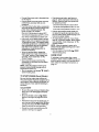
LUBRICATION
- EVERY
Plate
(Require
No
Lubrication)
between tdction
wheel and disc drive
Place coin in gap
plate
[_]_3--Grease
grease
should be visible
Zerk
• Remove the bottom panel (see second
figure on page 20).
• Turn disc drive plate clockwise by hand
until grease zerk is clearly visible at front
center. See figure above.
• Place a coin or (a shim of equal thiokness) between the rubber friction wheel
and disc drive plate to prevent rubber friction wheel contacting the drive disc.
• To grease zerk, use a hand grease gun,
lubricate with a Hi Temp EP Moly grease
See inset of figure above. DO NOT over
fill or allow grease to come in contact with
the disc drive plate or friction wheel or
damage will result. Fill zerk only until
grease becomes visible below bearing assembly located under grease zerk see insert above.
IMPORTANT: Remove coin and ensure that
a gap exists between friction wheel and disc
drive plate.
NOTE: Clean all excess grease found on
friction disc hub.
CAUTION; Do not allow grease to contact
friction wheel and disc drive plate.
LUBRICATION
- BEFORE STORAGE
• Remove both wheels, grease (any automotive type grease) both axles, see figure
below, and replace wheels. Do this at
least once a year and/or prior to storage.
25 HOURS
• Lubricate Disc Drive Plate every twentyfive (25) hours and at the end of the season and/or before storage.
Axle
To Lubricate:
• Position speed selector lever in first gear.
• Stand the snow thrower up on the auger
housing end.
16
LUBRICATION
OIL RECOMMENDATION
• Hex Shaft and Gears - Hex shaft and
gears require no lubrication. All bearings
and bushings are lifetime lubricated and
require no maintenance.
NOTE: Any greasing or oiling of the above
components can cause contamination of
the friction wheel. If the disc drive plate or
friction wheel comes in contact with grease
or oil, damage to the friction wheel will result.
Only use high quality detergent oit rated
with AP_ service classification SG. Select
the oil's viscosity grade according to your
expected operating temperature:
NOTE: For extreme cold operating conditions of 0° and below, use a partial synthetic
0W30 motor oil for easier starting.
Should grease or oil come in contact with
the disc drive plate or friction wheel, be sure
to clean the plate and wheel thoroughly.
NOTE: For storage, the hex shaft and
gears should be wiped with 5W-30 motor oil
to prevent rusting. See second figure on
page 15.
• Auger Gear Box - The auger gear box is
lubricated at the factory and should not
require additional lubrication. If for some
reason the lubricant should leak out, or if
the auger gear box has been serviced,
add Lubriplate No. 630-AA or equivalent.
Maximum 3-1/4 ounces should be used.
Remove filler plug as seen in figure below
once a year. If grease is visible, do not
add. If grease is not visible, use a piece
of fine wire like a dipstick, to check if
there is grease in the gearbox. Add
grease if necessary. Reinstall gear box
filler.
Change the oil every twenty-five (25) hours
thereafter, and at the beginning of each
season.
• Position the snow thrower so that the oil
drain plug is at the lowest point on the
engine. Remove the oil drain plug and
the oil fill cap/dipstick. Drain the oil into a
suitable container. Oil will drain more
freely when warm.
• Replace the oil drain plug and tighten securely.
SPARK PLUG
Make sure that the spark plug is tightened securely into the engine and the
spark plug wire is attached to the spark
plug.
If a torque wrench is available, torque
plug to 18 to 23 foot pounds.
Clean the area around the spark plug
base before removal to prevent dirt from
entering the engine.
Clean the spark plug and reset the gap
periodically at .030 inch.
Gear Box Filler
Plug
ENGINE
LUBRICATION
Check the crankcase oil level (see figure below) before starting the engine and after
each five (5) hours of continuous use. Add
S.A.E. 5W30 motor oil as needed. Tighten
fill cap/dipstick securely each time you
check the oil level.
17
tween the scraper bar and the sidewalk or
area to be cleaned. The scraper bar may
have to be returned to its original lower setting to maintain the original performance
level. To adjust:
• Position the snow threwer on a level surface.
Z_ CAUTION:
Always disconnect the
spark plug wire and tie back away from
the plug before making any adjustments
or repairs.
TO ADJUST SKID HEIGHT
This snow thrower is equipped with two
height adjustment skids, located on the outside of the auger housing (see figure below). These skids elevate the front of the
snow thrower.
• Make sure both tires are equally inflated.
• Loosen the carriage bolts and nuts securing the scraper bar to the auger housing.
• Adjust the scraper bar to the proper position.
• Tighten the carriage bolts and nuts, making sure that the scraper bar is parallel
with the working surface.
• For extended operation, the scraper bar
may be reversed. If the scraper bar must
be replaced due to wear, remove the carriage bolts and nuts and install a new
scraper bar.
Height Adjust Skids
Skid Mounting
/_.
CAUTION:
Be certain to maintain
proper ground clearance for your particular area to be cleared. Objects such as
gravel, rocks or other debris, if struck by the
impeller, may be thrown with sufficient force
to cause personal injury, property damage
or damage to the snow thrower.
For normal hard surfaces, adjust the skids
as follows:
• Check tire pressure (14 pounds). See
side of tire for maximum inflation. Do not
exceed maximum pressure on side of
tire.
• Place the extra shear bolts supplied
(found in parts bag) under each end of
the scraper bar near but not under the
skid.
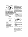
TO ADJUSTTHE
CLUTCH CONTROL
CABLES
Periodic adjustment of the cables may be
required due to normal stretch and wear on
the belts. To check for correct adjustment,
disconnect "Z" Fitting at clutch lever, move
clutch lever to the full forward position, just
contacting the plastic bumper. The control
cables are correctly adjusted when the center of the "Z" fitting is between the center
and top of the hole and there is no droop in
the cable (see figure below). If adjustment is
necessary:
• Loosen the skid mounting nuts (see figure above) and adjust the skids up to
bring the front of the snow thrower down.
• Re-tighten the mounting nuts.
• Set the skid on the other side at the same
height.
For rocky or uneven surfaces, adjust the
skids as follows:
• Raise the front of the snow thrower by
moving the skids down. This will help prevent rocks and other debris from being
picked up and thrown by the auger.
NOTE: Be sure that snow thrower is set at
same height on both sides.
Control Lever
must be in full
Aug
"Z" Fitting
when checking
TO ADJUST SCRAPER BAR
After considerable use, the metal scraper
bar will have a definite wear pattern. The
scraper bar in conjunction with the skids
should always be adjusted to allow 1/8" be-
Plastic Bumper
18
• Remove fuel from tank, and stand blower
on end,
• Pull rubber boot off the top of the spdng.
Push the cable through the spring (see
figure below) to expose the threaded portion of the cable.
Cable spring_
_
--
Square end
TO REPLACE BELTS
The drive belts on this snow thrower are of
special construction and should be replaced
with original equipment belts available from
your nearest Craftsman Store or Service
Center.
You will need the assistance of a second
person while replacing the belts.
Drain the gasoline from the fuel tank by removing the fuel line at the carburetor. Drain
the gas into a container and reinstall the
fuel line.
Locknut
CAUTION:
Drain the gasoline outdoors,
away from the fire or flame.
AUGER DRIVE BELT
If your snow thrower will not discharge
snow, and the auger drive belt (see figure
below for location) is damaged, replace it
as follows:
Au
• Hold the square end of the threaded portion with pliers and adjust the Iocknut in or
out until the excess slack is removed.
Pulley
• Pull the cable back through the spring
and connect the cable.
DrLveBelt
Drive Belt
er Drive
Pulley
iuide
• Do the same for the other lever cable, if
needed.
NOTE: Whenever the traction drive or auger belts are adjusted or replaced, the
cables will need to be adjusted.
Idler Pulley
Auger
Pulley
TO ADJUST BELTS
Belts stretch during normal use, If you need
to adjust the belts due to wear or stretch,
proceed as follows:
AUGER DRIVE BELT
If your snow thrower will not discharge
snow, check the control cable adjustment. If
it is correct, then check the condition of the
auger drive belt. It may be loose or damaged. If it is damaged, replace it (see To
Replace Belts paragraph on this page).
TRACTION
• Disconnect the spark plug wire.
• Remove the belt cover (See figure
below).
Belt C_
DRIVE BELT
The traction drive belt (see next figure) has
constant spring pressure and does not require adjustment.
1/4 X 1/2 In :hse f-tapping Screw
• Loosen the belt guide (see first figure this
column) and pull away from the engine
drive pulley.
• Replace the traction drive belt if it is slipping (see To Replace Belts paragraph on
this page).
19
• Loosen nut on the auger idler pulley (see
first figure this column) and pull idler
pulley away from the belt.
• Remove top two bolts that secure auger
housing to motor mount frame. Loosen
bottom two botts, Auger housing and
motor mount frame will
separate, hinged
by bottom two bolts.
• Remove old bell from auger drive pulley.
• Install the original equipment replacement
belt in reverse order of removal.
• Measure the distance between the belt
guide and the belt (see figure below). The
distance should be 1/8".
• If adjustment is necessary, loosen the
belt guide mounting bolt. Move the belt
guide to the correct position and tighten
the mounting bolt.
• Reinstall the belt cover.
• Reconnect the spark plug wire.
• Position drive belt onto the auger ddve
.("_X_
pulley.
• Adjust the belt guide (see To Adjust The
Belt Guide paragraph).
• Reinstall the belt cover.
NOTE: You may have to move the auger
idler pulley more than once to obtain the correct tension.
• Check the clutch control cable adjustment.
• Reconnect the spark plug wire.
TRACTION DRIVE BELT
If your snow thrower will not move forward,
check the traction ddve belt (see second
figure on page 19) for wear (Check other
causes also in the Trouble Shooting Points
section). Ifthe traction drive belt needs to be
replaced, proceed as follows:
• Disconnect the spark plug wire.
• Remove the belt cover (see second figura).
• Loosen the belt guide and pull away from
auger drive pulley (see second figure on
page 19).
• Remove auger drive belt from auger pulley (see second figure on page 19).
• Pull the traction ddve belt idler pulley
away from the traction drive belt (see
second figure on page 19).
• Remove the traction ddve belt.
• Position new traction ddve belt onto traction pulley.
• Pull idler pulley away from belt, allowing
beltto be positioned onto auger pulley.
• Check clutch control cable adjustment,
see page
• Reconnect the spark plug wire.
TO ADJUSTTHE
Drive Pulley
Auger Idler--_
_
TO ADJUST
Impeller
THE
FRICTION
WHEEL
If the snow thrower will not move forward,
you need to check the traction drive belt, the
traction ddve cable or the friction wheel, if
the friction wheel is damaged, it will need to
be replaced (see the To Replace Friction
Wheel paragraph on page 21). If the friction
wheel is not worn, check the adjustment, as
follows:
• Disconnect the spark plug wire.
• Drain the gasoline from the gas tank.
• Stand snow thrower on the auger housing
end.
• Remove the bottom panel (see figure below).
Remove Bolts
_Bo_om
Pane
Remove
To0
(Each
Side)
"_'_"
Looser_bottombol_
(Bo_om View)
' (each side)
• Position the shifter lever in first (1) forward gear.
• Note the position of the friction wheel on
the disc drive plate.Proper position from
the right outer side of disc drive plate to
the center of friction wheel should be 3"
(76 mm) (see next figure).
BELT GUIDE
• Disconnect the spark plug wire.
• Remove the belt cover (see third figure
on page 19).
• Engage the auger drive clutch lever.
20
" --.exS.e.
• Remove the bottom panel (see last figure
on page 20).
• Remove the three (3) fasteners securing
the friction wheel to the hub (see next figure).
• Remove the four bolts securing the bearing plates (both sides), (see figure be-
low).
Friction Wheel
3"
If adjustment is necessary:
• Remove washer and cotter pin connecting trunnion nut to speed rod (see figure
below).
• Twist trunnion nut up or down on shift rod
to obtain the correct friction wheel position.
• Put end of trunnion nut through hole in
speed control rod and reattach washer
and cotter pin,
• Replace bottom panels.
Bearing
Plate Bolts
Fasteners
(Bolts,
Auger
/
end nuts).
/
i
%
.,-'
[
=
Speed ControlRod
-,, ' JTrunnion
/
L_
• Remove right side bearing plate. Leave
hex shaft in odginal position.
• Remove friction wheel from hub. Slip friction wheel off hex shaft towards right
side.
TO REPLACE FRICTION
• Position new fnction wheel onto hub (see
first figure on page 22).
• Install bearing plates to enginal position.
Ensure hex shaft is engaged with both
bearing plates.
WHEEL
If the snow thrower will not move forward,
and the friction wheel is worn or damaged,
you need to replace it as follows: (First allow
the engine to cool).
• Drain the gasoline from the fuel tank by
removing the fuel line at the carburetor.
Drain the fuel in a container and reinstall
the fuel line.
• Secure bearing plates, using bolts removed earlier.
• Secure friction wheel to hub using fasteners removed earlier. Ensure hex shaft
turns freely.
• Replace bracket to speed control lever.
• Reconnect speed control rod to speed
rod by reassembling the trunnion assembly and cotter pin.
NOTE: Ensure friction wheel and friction
disc are free from grease or oil.
• Replace bottom panel.
• Lower the snow thrower onto the tires.
CAUTION:
Drain gasoline outdoor away
from fire or flame.
• Disconnect the spark plug wire.
• Stand the snow thrower up on the auger
housing end,
• Disconnect speed control rod from speed
rod by removing cotter pin (see figure
above). Keep trunnion in same position
on speed control rod. Movement of the
trunnion will result in speed changes.
21
TO ADJUST OR REPLACE
FdctionWheel
THE SPARK PLUG
NOTICE: This spark ignition system meets
all requirements of the Canadian Interference-Causing Equipment Regulations.
NOTICE: This engine complies with all current Australian and New Zealand Umitaions
regarding electromagnetic interference.
If you have difficulty starting your snow
thrower, you may need to adjust or replace
the spark plug. Follow the instructions below.
Bolt
Nut
TO REPLACE AUGER SHEAR BOLT
The augers are secured to the auger shaft
with special bolts (see figure below) that are
designed to break (to protect the machine)
if an object becomes lodged in the auger
housing. Use of a harder bolt will destroy the
protection provided by the shear bolt.
IMPORTANT: To ensure safety and performance (evels, only originalequipment shear
belts shouldbe used.
Replace the spark plug if the electrodes are
pitted or burned or if the pomelain is
cracked.
TO ADJUST:
• Clean the spark plug by carefully scraping the electrodes (do not sand blast or
use a wire brush).
• Be sure the spark plug is clean and free
of foreign material Check the electrodes
gap (see figure below) with a wire feeler
gauge and reset the gap to .030 inch if
necessary.
'-: I_
I :
Locknut=_
E_
• To replace a broken shear bolt, proceed
as follows:
TO REPLACE:
• If you need a new spark plug, use only
the proper replacement spark plug (see
page 15).
• Set the gap to .030 inches.
• Before installing the spark plug, coat its
threads lightly with oil or grease to insure
easy removal.
• Tighten the plug firmly into the engine.
• If a torque wrench is available, torque the
plug to 18 to 23 ft. - Ibs.
• Move the throttle to O (STOP) and turn
off all controls.
• Disconnect the spark plug wire. Be sure
all moving parts have stopped.
• Lubricate the auger shaft zerk fitting (See
the Maintenance
section ).
• Align the hole in the auger with the hole
in the auger shaft. Install the new shear
bolt and nut found in toolbox located on
top of belt cover.
TO ADJUST CARBURETOR
• Reconnect the spark plug wire.
If you think your carburetor needs adjusting,
see your nearest Authorized Craftsman
Service Center. Engine performance
should not be affected at altitudes up to
7,000 feet. For operation at higher elevations, contact your nearest Craftsman Service Center.
22
it_ CAUTION:
Never store your snow
thrower indoors or in an enclosed, poody
ventilated area if gasoline remains in the
tank. fumes may reach an open flame,
spark or pilot light from a furnace, water
heater, clothes dryer, cigarette, etc.
To prevent engine damage (if snow thrower
is not used for more than 30 days} follow
the steps below.
SNOW THROWER
Carburetor Bowl
STORAGE
• Thoroughly clean the snow thrower.
• Lubricate all lubrication points (see the
Maintenance section on pages 15- t 7).
• Be sure that all nuts, bolts and screws are
securely fastened, inspect all visible moving parts for damage, breakage and wear.
Replace if necessary.
• Touch up all rusted or chipped paint surfaces; sand lightly before painting.
• Cover the bare metal parts of the blower
housing auger and the impeller with rust
preventative, such as a spray lubricant.
NOTE: A yearly checkup or tune-up by a
Craftsman Service Center is a good way to
insure that your snow thrower will provide
maximum performance for the next season.
Always follow instructions on stabilizer container. Then run engine at least 10 minutes
after stabilizer is added to allow mixture to
reaCh carburetor. Store snow thrower in a
safe place. See Caution on this page.
You can keep your engine in good operating
condition during storage by:
• Changing oil (see page 17).
• Lubricating the piston/cylinder area. This
can be done by first removing the spark
plug and squirting a few drops of clean
engine oil into the spark plug hole. Then
cover the spark plug hole with a rag to
absorb oil spray. Next, rotate the engine
by pulling the starter rope fully out two or
three times. Finally, reinstall spark plug
and attach spark plug wire.
ENGINE STORAGE
OTHER
Gasoline must be removed or treated to prevent gum deposits from forming in the tank,
filter, hose, and carburetor during storage.
Also during storage, alcohol blended gasoline that uses ethanol or methanol (sometimes called gasohol) attracts water. It acts
on the gasoline to form acids which damage
the engine.
• To remove gasoline, run the engine until
the tank is empty and the engine stops.
Then drain remaining gasoline from carburetor by pressing upward on bowl drain
located on the bottom of carburetor (see
next figure).
• If possible, store your snow thrower indoors and cover it to give protection from
dust and dirt.
• _fthe machine must be stored outdoors,
block up the snow thrower to be sure the
entire machine is off the ground.
• Cever the snow thrower with a suitable
protective cover that does not retain
moisture. Do not use plastic or vinyl.
IMPORTANT:
Never cover snow thrower
while engine and exhaust areas are still
warm.
• If you do not want to remove gasoline, a
fuel stabilizer (such as Craftsman Fuel
Stabilizer No. 33500) may be added to
any gasoline |eh in the tank to minimize
gum deposits and acids. If the tank is almost empty, mix stabilizer with fresh gasoline in a separate container and add some
to the tank.
23
TROUBLE
CAUSE
CORRECTION
Difficult starting
Defective spark plug
Water or dirt in fuel system
Replace defective plug
Use carburetor bowl drain to
flush and refill with fresh fuel
Engine runs erraticeliy
Blocked fuel line or low on fuel
Clean fuel line; check fuel supply; add fresh gasoline (gasoline/oil mixture if 2-cycle engine)
Engine stalls
Unit running on CHOKE
Move choke lever to OFF positior
Engine runs erratically;
Loss of power
Water or dirt in fuel system
Use carburetor bowl drain to
flush and refill with fresh fuel
Excessive
vibration
Loose parts; damaged impeller
Stop engine immediately and
disconnect spark plug wire.
Tighten atl bolts and make all
necessary repairs, if vibration
continues, have the unit serviced by a Craftsman service
repairman
Units fails to
_ropei itself
Ddve belt loose or damaged
Adjust auger drive belt: Replace
if damaged
Incorrect adjustment of auger contrel cable
Adjust traction drive cable
Unit fails to
discharge snow
Headlight does
not work
Norn or damaged friction wheel
Repair friction wheel
Auger drive belt loose or damaged
Replace auger drive belt
Auger control cable not adjusted
correctly
Adjust auger control cable
Shear bolt broken
Replace shear bolt
Discharge chute clogged
Stop engine immediately and dis
connect spark plug wire. Clean
discharge chute and inside of au
ger housing
Foreign object lodged in auger
Stop engine immediately and dis.
connect spark plug wire. Remov_
object from auger.
Loose wire connection
Tighten connection
Bulb burned out
Replace headlight bulb
24