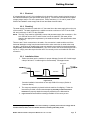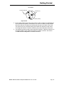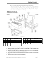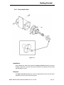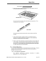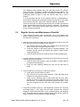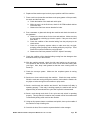
1
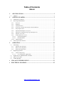
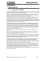
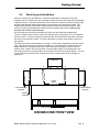
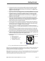
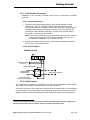
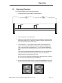
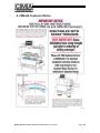
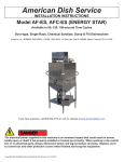
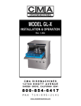
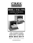
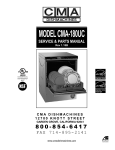
MODEL CMA-66
Installation & Operation
Rev 1.06
CMA DISHMACHINES
12700 KNOTT AVENUE
GARDEN GROVE, CALIFORNIA 92841
800-854-6417
FAX 714-895-2141
www.cmadishmachines.com
Table of Contents
CMA-66
1.
SPECIFICATIONS................................................................................................. 2
1.1
2.
CMA-66.......................................................................................................................................... 2
GETTING STARTED ............................................................................................ 3
2.1.
Introduction to CMA-66................................................................................................................. 3
2.2.
Receiving and Installation .............................................................................................................. 4
2.2.1.
Electrical ................................................................................................................................ 5
2.2.2.
Plumbing................................................................................................................................. 5
2.2.3.
Installation Notes.................................................................................................................... 5
2.2.4.
Scrap Tray Assembly and Overflow Chute Installation.......................................................... 7
2.2.5.
Pump Impeller Note................................................................................................................ 8
2.2.6.
Optional Hood Adapter (set of two) ....................................................................................... 9
2.2.7.
Optional Freestanding Scrap Trap and Adaptor Kit ............................................................ 10
2.2.8.
Optional “Auto-Fill”............................................................................................................ 11
2.2.9.
Field Installed Accessories ................................................................................................... 14
2.2.9.1.
Chemical Dispensers .................................................................................................... 14
2.2.9.2.
Hood Fan Motor ........................................................................................................... 14
2.2.10. CMA-66 Heater .................................................................................................................... 14
2.3. Safety Tips for the CMA-66 ......................................................................................................... 15
3.
OPERATION ........................................................................................................ 16
3.1.
Initial Setup .................................................................................................................................. 16
3.1.1.
Optional Auto Fill Timer ...................................................................................................... 16
3.1.2.
Rinse Pressure Regulator ..................................................................................................... 16
3.1.3.
Wash Tank Temperature....................................................................................................... 16
3.2. Beginning Operation..................................................................................................................... 17
3.2.1.
Chemical Dispensing ............................................................................................................ 18
3.2.1.1.
Low Temperature Applications .................................................................................... 18
3.3. Regular Service and Maintenance Checklist ................................................................................ 19
3.4.
Quick service guide ...................................................................................................................... 21
3.5.
Trouble Shooting .......................................................................................................................... 22
4.
CMA-66 CUSTOMER NOTICE ............................................................................ 23
5.
ELECTRICAL DIAGRAM .................................................................................... 25
www.cmadishmachines.com
1. Specifications
1.1
CMA-66
CMA-66
L.T.
CMA-66
H.T.
WATER CONSUMPTION
PER RACK
.8 GAL.
.94 GAL.
PER HOUR
192 GAL.
192 GAL.
6.75
5.7
242
205
WASH (MIN)
140° - 150° F
150° - 160° F
FINAL RINSE (MIN)
140° - 150° F
180° - 195° F
140° F
180° F
CONVEYOR SPEED
FEET PER MINUTE
OPERATING CAPACITY
RACKS PER HOUR (NSF rated)
OPERATING TEMPERATURE
WATER REQUIREMENTS
INLET TEMPERATURE (MIN)
WATER INLET SIZE
3/4”
FINAL RINSE SIZE
1/2”
DRAIN SIZE
2”
FINAL RINSE PRESSURE
20 PSI
18.5 GAL.
HOLDING TANK CAPACITY
PUMP CAPACITY
(ALL PUMPS)
38 GPM (each)
MOTORS
WASH PUMP (3)
1 HP
CONVEYOR
1/3 HP
DIMENSIONS
DEPTH
25”
WIDTH
66”
HEIGHT
STANDARD TABLE HEIGHT
55 ½”
32 ½” adjusts to 34”
MAX CLEARANCE FOR DISHES
19”
STRANDARD RACKS
ELECTRICAL RATING
19 ¾” x 19 ¾”
VOLTS
PHASE
AMPS
208
1
61
240
1
65
208
3
38
240
3
42
HEATER
10 kW
SHIPPING WEIGHT
APPROXIMATE
MODEL CMA-66 Installation & Operation Manual Rev. 1.06 01/11/05
750#
Page 2
Getting Started
2. Getting Started
2.1.
Introduction to CMA-66
The CMA-66 is designed to give maximum cleaning in 66 inches. It represents the cleaning
power of machines twice its length. The curtains incorporated in the machine minimize transfer
from tank to tank during the wash and sanitizing procedures.
Energy costs for running the CMA-66 have been greatly reduced by the introduction of stage
washing. This design allows the heavy food soil to be removed in the first station, which provides
a relatively clean dish before it reaches the wash stage in the center tank.
The supply water to the CMA-66L must be a minimum of 140°F, while the CMA-66H requires two
supply lines; one at a minimum water temperature of 180°F (for RINSE), and the other at a
minimum temperature of 140° F (for FILL). Either model requires the supply water to be provided
at 24-PSI (Pounds per Square Inch) minimum with 6 GPM (Gallons Per Minute) flow rate and 200
GPH (Gallons Per Hour) recovery rate. The pipe supplying the water must be 3/4”. The plumbing
connection is located at the top back of the machine.
The CMA-66 features a scrap tray that may be emptied on a periodic basis without interruption of
the flow of work and the manner in which the tank is filled ensures that the dishes are always
rinsed with fresh water instead of re-circulated water. The CMA-66L is designed to deliver 0.8
gallons of fresh rinse water and the CMA-66H is designed to deliver 0.94 gallons of fresh rinse
water for each rack. This water flows from the rinse and power wash tank into the pre-wash tank
and then overflows into the scrap tray carrying debris with it, thereby providing a much cleaner
environment for the wash and rinse cycles.
A single-phase CMA-66 is available for installations where the only power available is 208V230V/1-PH.
There are also enhancements that can be chosen when desired such as an optional “Auto-Fill”
function, optional Vent Hood Adaptors and other machine accessories such as stainless steel
dishtables. Call (800) 854-6417 for more information.
This manual is structured to provide a complete reference guide to the CMA-66. It is presented in
a manner that all users will be able to comprehend and use as an effective tool in supporting the
operation and maintenance of the dishmachine. The first section explains how the machine is
packaged and what to look for when receiving the machine.
Instructions are provided in the manual explaining how to unpack the machine and then install
and set up the machine for use. Requirements are given for plumbing, wiring, and space
considerations. These attributes of the machine are always taken into consideration by our welltrained sales representatives prior to the order being placed. In the manual, additional installation
guidance is given to ensure the machine can run at optimum conditions.
The Operation Section of the manual may be used for instruction and procedures when required.
We make this portion of the manual easy to understand so that all levels of operators may be
able to read and comprehend the operation of the machine. The function of the machine itself is
mostly automatic and takes little training to put into full operation. The Operation Section also
includes diagnostic considerations for the machine when problems occur.
We are committed to providing the best machines and customer service in the food industry and
your feedback is welcome.
MODEL CMA-66 Installation & Operation Manual Rev. 1.06 01/11/05
Page 3
Getting Started
2.2.
Receiving and Installation
When you receive your new CMA-66, complete the assembly by installing the scrap tray
assembly with its overflow chute, the two wrapper shields and the curtain rods, which are shipped
inside the machine. After the box has been removed from the machine, remove the left and right
stainless steel wrapper shields and bolt them in place with the nuts and bolts provided. The
wrapper shield with the extra curtain clamps mounts onto the dirty end of the machine. Next,
mount the scrap tray assembly and overflow chute into position (see section 2.2.4 Scrap Tray
Assembly and Overflow Chute Installation).
All of the spray arms should be inserted and in place over the wash tank compartments.
There are a total of seven curtains used in the CMA-66; two are long-narrow, four are long-wide
and one is short. The two long-narrow curtains and the one short curtain have shorter rods than
the other four (long-wide) curtains. The short rods hold the curtains at the entrance and exit of
the machine.
The sketch below lists curtain positions 1 through 6. In this case, it represents a flow from left-toright. Reverse the sequence for right-to-left machines. If the dish flow is from left-to-right, the
proper sequence for the placement of the curtains would be: long-narrow curtain in the first
position; short curtain in the second position; two short-wide curtains in the third position; two
short-wide curtains in the fourth position; and a long-narrow curtain in the sixth position. The only
curtain change to reverse the flow of dishes is the short curtain at position #2 is changed to
position #5.
CMA-66
3
1
4
2
5
6
SHORTWIDE
CURTAINS
LONG-NARROW
CURTAIN
LONG-NARROW
CURTAIN
SHORT
CURTAIN
DISH FLOW
DISHMACHINE FRONT VIEW
MODEL CMA-66 Installation & Operation Manual Rev. 1.06 01/11/05
Page 4
Getting Started
2.2.1. Electrical *
A 3-phase 208-240 volt AC, 60 Hz dedicated circuit should be used to supply electrical energy to
the CMA-66 dishwasher (see specification sheet page 2). Connect the wire that has the highest
voltage (stinger lead) to L-2 on the power block. Power lead wires (L1, L2 and L3) used for the
CMA-66 at installation must comply with all local and State electrical codes.
2.2.2. Plumbing*
The water supply connection is made with a ½” hot water line to the water supply inlet on the top
of the machine. The water supplied to the machine must be a minimum of 140° F for the CMA66L and a minimum of 180° F for the CMA-66H.
NOTE: The High Temp machine (CMA-66H) comes with two water supply line connections. One
is for the final rinse at 180° F and the other is to fill the machine—this water will be
heated to the appropriate temperature by the wash tank heater. (See specification sheet
on page 2).
There are two 2” drain connections to be made. One connection is made at either end of the
horizontal drainpipe coming from the wash tank and the other connection is made at the scrap
tray drain. (Instructions for installing the scrap tray assembly are provided in section 2.2.4 Scrap
Tray Assembly and Overflow Chute Installation.) One of the ends of the horizontal drainpipe has a
cap on it – simply move the cap to the other end if it’s currently on the end needed for the drain
connection.
2.2.3. Installation Notes
1. Tables must slant into the machine for proper drainage (for each 28" of table length
a drop of at least ¾” in table height is recommended). See Figure 2.2.3a.
FRESH WATER
TABLE SLANT
TO SCRAP
ACCUMULATOR
PREWASH
WASH/RINSE
DISH FLOW
Figure 2.2.3a
See also installation instructions on new style CMA-66 conveyor (Section 4.
Customer Notice)
2. The scrap tray assembly is placed inside the machine for shipping. Follow the
instructions provided in section 2.2.4 Scrap Tray Assembly and Overflow Chute
Installation to properly attach the scrap tray assembly to the dishmachine.
3. Figure 2.2.3b shows the different settings available on the conveyor cam.
*
Electrical and plumbing connections must be made by a qualified person who will comply with all
available Federal, State, and Local Health, Electrical, Plumbing and Safety codes
MODEL CMA-66 Installation & Operation Manual Rev. 1.06 01/11/05
Page 5
Getting Started
P/N 13505.10
205 RACKS (CMA-66H)
167 RACKS (M-1)
B
A
C
242 RACKS (CMA-66L)
Figure 2.2.3b
4. On a 3-phase machine the water pump motors are also 3-phase and, depending on
which terminal each phase is connected to, the motor can rotate in either direction.
Check the direction of rotation by removing the dust cap on the back of the motor.
The motors must turn clockwise looking at the shaft from the back of each motor.
To change the direction of rotation, switch any two power lead wires at the motor.
5. The machine must be running to set the pressure regulator. While the machine is in
the FINAL RINSE CYCLE, adjust the pressure regulator to 20 PSI. See section
3.1.2 Rinse Pressure Regulator for detailed instructions.
MODEL CMA-66 Installation & Operation Manual Rev. 1.06 01/11/05
Page 6
Getting Started
2.2.4. Scrap Tray Assembly and Overflow Chute Installation
The scrap tray assembly and overflow chute, which came packaged inside the
machine, can easily be installed by executing the following steps: Figure 2.2.4 below
illustrates the assembly as it would appear for a Left-to-Right machine – a Right-toLeft machine would simply be the mirror image.
Caution: For proper spacing, the
SS flat washer (item 2) must not be
located between the head of the
trusshead bolt and the inside of the
machine.
Figure 2.2.4
ITEM NO.
NO. REQ’D
P/N
DESCRIPTION
ITEM NO.
NO. REQ’D
P/N
DESCRIPTION
1
7
00905.00
¼-20 X ½” Trusshead Bolt
6
4
00906.00
2
11
00924.00
¼” SS Flat Washer
7
1
17579.00
Scrap Trap Holder
3
11
00912.00
¼-20 Nylon Lock Nut
8
1
01579.10
Scrap Trap Body Molded
9
1
01579.20
Scrap Trap Drawer Molded
4
1
13511.26
CMA-66P Overflow Gasket
5
1
13511.06
CMA-66P Overflow Chute (L-R)
13511.16
CMA-66P Overflow Chute (R-L)
¼-20 X ½” Hex Head Bolt
1. Remove the items from their packing and verify that all the pieces are present.
2. Attach the overflow chute with the five ¼-20 X ½” trusshead bolts, ¼” SS Flat Washers, and
¼-20 Nylon Lock Nuts provided.
3. Secure the scrap trap holder to the dishmachine using the four ¼-20 X ½” Hex Head Bolts,
¼” SS Flat Washers, and ¼-20 Nylon Lock Nuts provided.
4. Set the scrap trap body—with the scrap trap drawer inserted—into position on the scrap trap
holder.
5. Attach the drain as specified in section 2.2.2 Plumbing.
MODEL CMA-66 Installation & Operation Manual Rev. 1.06 01/11/05
Page 7
Getting Started
2.2.5. Pump Impeller Note
Figure 2.2.5
Installation:
When installing the water pump impeller the Nylon Lock Nut indicated by the arrow
in Figure 2.2.5 must be in place to prevent the impeller from spinning off of the shaft
and damaging the motor.
Removal:
The Nylon Lock Nut indicated by the arrow in Figure 2.2.5 must be removed before
attempting to remove the water pump impeller.
MODEL CMA-66 Installation & Operation Manual Rev. 1.06 01/11/05
Page 8
Getting Started
2.2.6. Optional Hood Adapter (set of two)
An optional Hood Adapter set (P/N 13901.82) is available.
proper installation are given below.
The dimensions for
75-½"
9-½"
65"
Leg Adj
66”
MODEL CMA-66 Installation & Operation Manual Rev. 1.06 01/11/05
Page 9
Getting Started
2.2.7. Optional Freestanding Scrap Trap and Adaptor Kit
The optional Freestanding Scrap Trap (P/N 01560.00) and Adaptor Kit (P/N
13512.00) are available for installations where the space is insufficient to
accommodate the standard side-mounted scrap trap or where drain access is easier
by locating the scrap trap some distance away from the Dishmachine.
*
ITEM NO.
NO. REQ’D
P/N
DESCRIPTION
ITEM NO.
NO. REQ’D
P/N
DESCRIPTION
1
11
00912.00
1/4-20 Nylon Lock Nut
5
1
13511.26
Overflow Gasket
2
1
01307.00
Scrap Trap Flange Nut
6
2
00914.00
1/4-20 x 3/4" Hex Head Bolt
3
1
01308.00
Scrap Trap Flange Gasket
7
1
13512.00
Scrap Trap Adaptor
4
1
13512.10
Scrap Trap Adaptor Flange
8
1
01560.00
Scrap Trap, Freestanding
*Not Supplied
MODEL CMA-66 Installation & Operation Manual Rev. 1.06 01/11/05
Page 10
Getting Started
2.2.8. Optional “Auto-Fill”
With this function a single press of the AUTO FILL switch fills the machine to the
proper level.
If your Dishmachine did not come with the Auto-Fill option already installed, an
Auto-Fill kit is available. Call (800) 854-6417 and order Kit #13468.00
Kit #13468.00 Includes:
ITEM
QTY
P/N
1
2
3*
4
5
6
7
8
9
10
11
1
1
1
1
1
1
2
2
2
2
2
00421.89
13418.85
13419.85
13003.61
00705.05
00400.10
00401.10
00907.00
00965.00
00661.00
52000.00
DESCRIPTION
Rocker Switch, Momentary
Timer Relay
Timer Relay Socket
DIN Rail, 3” (with 2-sided tape)
Solenoid Valve
1/2" Conduit, 2 feet
1/2" Straight Connector
6-32 x 1/2" Pan Head Screw
6-32 Nylon Lock Nut
Wire Nut
#250 Piggyback Connector
*Item 3: Socket is pre-wired for easy installation
To Install:
1. Disconnect the machine from power at the circuit breaker.
!
Warning! Turning the machine off at its power switch is not sufficient, as a
shock hazard is still present. Power must be disconnected at the circuit
breaker.
1. With the water supply turned off at the source remove the manual fill valve and replace it
with the Solenoid Valve *, (P/N 00705.05).
2. Depending on which control cabinet came installed on your machine, there will either be
an area of open DIN rail for mounting the pre-wired Timer Relay Socket (P/N 13419.85)
or there will be two predrilled holes in the upper-right corner. If there is no open area on
the DIN rail but the two holes are present, mount the DIN Rail (P/N 13003.61) inside the
control cabinet using the two 6-32 x 1/2" Pan Head Screws (P/N 00907.00) and 6-32
Nylon Lock Nuts (P/N 00965.00). The screws should be inserted through the DIN Rail
and out the back of the control cabinet.
3. Secure the pre-wired Timer Relay Socket (P/N 13419.85) to the DIN Rail by snapping it
into place. See Figure 1 on the following page for orientation of socket.
4. Remove the blue wire from the Main Contactor coil terminal (see Figure 2 on the
following page) and put one of the two #250 Piggyback Connectors (P/N 52000.00) on
the coil terminal.
**
Electrical and plumbing connections must be made by a qualified person who will comply with all
available Federal, State, and Local Health, Electrical, Plumbing and Safety codes
MODEL CMA-66 Installation & Operation Manual Rev. 1.06 01/11/05
Page 11
Getting Started
Auto-Fill Timer Relay Socket
5
6
8
7
10
4
9
2
3
Top
To coil terminal (blue) of main contactor
Blue
11
1
of Cabinet
Violet
Blue
Red
Red
Violet
Red
To coil terminal (red) of main contactor
Blue/Yel
Blue/Yel
Orange
Orange
Violet
Figure 1
} To solenoid
Violet
To Auto Fill switch
(Rocker Switch)
Control Panel
+
+
+
+
+
+
+
+
+
+
8
+
+
7
+
10
6
Heater
Contactor
9
11
5
+
Main
Contactor
+
Blue
1
2
4
+
+
+
+
+
+
+
+
+
+
+
3
Violet
Blue
Red
Red
Violet
Red
Blue/Yel
Blue/Yel
Orange
Orange
Violet
Violet
Coil
Coil
Terminal Terminal
(Red)
(Blue)
Figure 2
MODEL CMA-66 Installation & Operation Manual Rev. 1.06 01/11/05
Page 12
Getting Started
5. Connect the blue wire you removed from the Main Contactor coil terminal to the #250
Piggyback Connector and connect the blue wire from terminal 10 of the Timer Relay
Socket to the same #250 Piggyback Connector on the coil terminal. See Figure 1 and
Figure 2 on the previous page.
6. Remove the red wire from the Main Contactor coil terminal (see Figure 2 on the previous
page) and put the other #250 Piggyback Connectors (P/N 52000.00) on the coil terminal.
7. Connect the red wire you removed from the Main Contactor coil terminal to the #250
Piggyback Connector and connect the red wire from terminal 11 of the Timer Relay
Socket to the same #250 Piggyback Connector on the coil terminal. See Figure 1 and
Figure 2 on the previous page.
8. Pop out the rocker switch hole plug from the Auto Fill switch position in the front panel.
There are two violet wires attached to it. Pull the two wires off of the hole plug and
connect them—either wire to either terminal—to the two terminals on the Rocker Switch
(P/N 00421.89) from the kit and insert the Rocker Switch into the hole. Position the
switch so that it rocks to the right when actuating.
9. The other ends of the two violet wires coming from the Rocker Switch are bundled into
the wire harness. Free up the ends for easy access. Connect the two violet wires from
terminals 2 and 6 of the Timer Relay Socket to the ends of the two violet wires coming
from the Rocker Switch. See Figure 1 on the previous page.
10. Using one of the two 1/2" Straight Connectors (P/N 00401.20) that came with the kit,
mount one end of the 1/2", 2 feet Conduit (P/N 00400.10) to a 7/8” hole in the back of the
control cabinet.
11. Secure the remaining 1/2" Straight Connector to the other end of the 1/2" Conduit and
route the blue/yel wire from terminal 10 of the Timer Relay Socket and the orange wire
from terminal 9 of the Timer Relay Socket through the 1/2" Conduit to the Solenoid Valve.
12. Using the two Wire Nuts (P/N 00661.00) connect the blue/yel wire and the orange wire to
the two wire leads coming from the solenoid—either wire to either wire. Connect the 1/2"
Conduit to the Solenoid Valve with the 1/2" Straight Connector.
13. Plug the Timer Relay (P/N 13418.85) into the Timer Relay Socket and check that it is set
up as follows:
OUT
POWER
a. Mode selected is “D”
Timer Dial
9
12
b. Scale displayed is “0 – 18”
c. Range selected is “10S”
6
15
d. Timer dial is set near 9 ½
0
MODE
D
Mode
idec
Scale
GT3A
18
RANGE
10S
Range
14. Turn on the machine and test your new Auto Fill feature.
When Auto Fill is activated (and the rinse pressure is set to 20 PSI), the machine should fill until it
begins to overflow into the scrap tray, at which point it should stop filling. If needed, adjust the
time setting on the Timer Relay to accomplish this.
Users note: If at any time less than a full Auto Fill cycle is desired the Auto-Fill can be interrupted
(stopped) by turning off the power to the machine. The machine will resume normal operation
upon restoring power without continuing the Auto Fill cycle.
MODEL CMA-66 Installation & Operation Manual Rev. 1.06 01/11/05
Page 13
Getting Started
2.2.9. Field Installed Accessories
Installation of the accessory chemical pumps must be performed by qualified
personnel.
2.2.9.1. Chemical Dispensers
1. Checkvalves should be installed directly at the mixing chamber coupling.
There are two 1/8” FPT mounting holes provided, which will position the
checkvalves parallel to the machine avoiding any chemicals from dripping onto
the stainless steel should a leak develop. Simply remove the plug from the
mounting hole and install the checkvalve—be sure to use a proper sealing
compound or Teflon tape on the threads * .
NOTE: There are two mounting holes provided on the mixing chamber coupling,
one for rinse chemical and one for sanitizer chemical, but only one is
needed with the CMA-66H—for rinse chemical only.
2. Connect only to the primary side of the Listed Class 2 Transformer, 208-230
VAC, 60 Hz, 100 VA maximum load.
2.2.9.2. Hood Fan Motor
TERMINAL BLOCK
DETERGENT SIGNAL
220 volts AC
T2
L2
FAN CONTACTOR
WIRES FROM THE
POWER SOURCE *
T1
L1
WIRES TO THE FAN MOTOR
* 220 VAC OR 110 VAC
SUPPLIED BY ELECTRICIAN
2.2.10. CMA-66 Heater
The 10kW heater located in the wash/final rinse tank has an independent power switch,
which needs to be activated when the machine is ready for operation.
As a safety precaution—if the wash tank is drained while the heater is left on, the thermostat
receives a signal to turn off the heater from a float switch located in the rinse end of the tank.
NOTE: The heater switch should always be turned off when the machine is not in operation.
* *
Electrical and plumbing connections must be made by a qualified person who will comply with all
available Federal, State, and Local Health, Electrical, Plumbing and Safety codes
MODEL CMA-66 Installation & Operation Manual Rev. 1.06 01/11/05
Page 14
Getting Started
2.3.
Safety Tips for the CMA-66
DANGER: Always turn off the circuit breaker at the wall when working on this
dishmachine. Even with the machine’s power switch off there is a live
connection coming to the switch, so turn off the circuit breaker as well.
CAUTION: Do not get in the path of the conveyor rocker arm or the conveyor’s moving
bar. Do not reach into the rocker arm area without first making sure the
dishmachine is turned off at the circuit breaker.
CAUTION: Do not open the front door when the machine is in operation.
CAUTION: Avoid spraying water on or around the electrical control box on the top of the
machine. When cleaning, do not spray water directly on the motors.
CAUTION: When removing the final rinse arms for cleaning, exercise caution. The final
rinse arms may be filled with chemicals and/or under pressure.
MODEL CMA-66 Installation & Operation Manual Rev. 1.06 01/11/05
Page 15
Operation
3. Operation
3.1.
Initial Setup
3.1.1. Optional Auto Fill Timer
When Auto Fill is activated, the machine should fill until it begins to overflow into the
scrap tray, at which point it should stop filling.
If necessary, adjust the time set on the Auto Fill Timer to allow an appropriate
amount of water flow to properly fill the Dishmachine. See Section Error! Reference
source not found. Error! Reference source not found. Item 3 (Note: With the Auto Fill
option there are two timers in the control box. The Auto Fill Timer is in the upperright corner of the control box).
Users note: If at any time less than a full Auto Fill cycle is desired, the Auto-Fill
can be interrupted (stopped) by turning off the power to the machine. The machine
will resume normal operation upon restoring power without continuing the Auto Fill
cycle.
3.1.2. Rinse Pressure Regulator
The CMA-66 requires a supply water pressure of 24 PSI minimum. The pressure is
then reduced by the supply water regulator. Use the following procedure to adjust
the rinse pressure to 20 PSI:
1. Close the door on the machine.
2. Turn the Power switch to the "ON" position.
3. Using a rod or something long to avoid contact with the rinse water, actuate
the final rinse trip switch—this activates the water solenoid. With the rinse
water flowing adjust the pressure regulator until the gauge reads 20 PSI.
Adjustment tip: Always adjust “down” when setting this pressure regulator. In
other words—intentionally raise the pressure above the desired set point and
then carefully bring it down to the correct pressure.
3.1.3. Wash Tank Temperature
The wash tank temperature for the CMA-66 is set at the factory. Should you ever
find a need to adjust it—after replacement of the thermostat for example—simply
perform steps 1 through 4 in section 3.2 Beginning Operation.
MODEL CMA-66 Installation & Operation Manual Rev. 1.06 01/11/05
Page 16
Operation
3.2.
Beginning Operation
To run the dishmachine, perform the following steps:
1. Close both drains (valve handles in vertical position).
CLOSE
CLOSE
2. Turn on the power to the dishmachine.
3. Open the fill-valve and fill the machine until it overflows out of the pre-wash
tank into the scrap tray or, if the Auto Fill option is present, press the AUTO
FILL switch to fill the machine with water.
4. Turn the heater on. The temperature of the water in the tank should be
140°F – 150°F. The Tank heater will maintain a minimum temperature of
140° F if the final rinse is providing 140°F – 150°F at all times (CMA-66L).
150°F minimum will be maintained if the final rinse is 180°F – 195°F (CMA66H).
If the thermostat (located behind the stainless steel cover on the final rinse
side of the machine) should need adjustment—there is a thermostat
adjustment access hole located on the cover.
Tip: If you are having difficulty maintaining wash tank temperature, minimize
the vent hood openings by closing off the dampers.
5. Be sure to place the dishes correctly. If they become dislodged, they could
interfere with the trip switch lever and interrupt the operation of the machine.
MODEL CMA-66 Installation & Operation Manual Rev. 1.06 01/11/05
Page 17
Operation
RACK TRAVEL
6. At the end of the shift and after heavy periods of accumulation, clean the
three strainer trays inside the machine.
STRAINER TRAY
Also, at the end of each shift, remove and clean the six spray arms. Then
reinstall them into the machine.
SPRAY ARM
Also, when water becomes heavily soiled, drain the tanks and refill the
machine.
7. Check chemical buckets. Make sure there is an adequate supply of
detergent, rinse aid and (CMA-66L only) sanitizer. Also, verify that the
pickup line is inserted into the correct bucket.
8. Slide in a dish rack to activate the cycle start trip switch on the pre-wash end
of the machine. The 60-second time-delay-off relay will hold the machine in
the run mode for 60 seconds after a rack releases the cycle start switch and
then shut off. This time-delay relay prevents the machine from continuing to
run when a dish rack is not in the machine.
3.2.1. Chemical Dispensing
The rinse and sanitizing agents are not injected during the initial fill stage. They are
injected into the final rinse make-up water when the final rinse trip switch is
activated in the final rinse tank.
3.2.1.1. Low Temperature Applications
See dispenser manufacturing operational
adjustments for Low Temp applications.
MODEL CMA-66 Installation & Operation Manual Rev. 1.06 01/11/05
instructions
for
sanitizer
Page 18
Operation
The sanitizing pump operates when the fresh water enters the machine
during final rinse. The water is treated at 50 PPM (parts per million). The
pressure regulator is adjusted to 20-PSI. This allows 0.8 (CMA-66L), or 0.94
(CMA-66H) gallons of water to enter the machine each time a rack is
washed.
It is recommended that the 5-1/2% chemical solution be standardized to
allow uniform dispensing of the sanitizing solution into the flow of rinse water
as the machine operates. At this level, maximum shelf life is available.
Inside the control box is a labeled power block for the sanitizer and rinse aid,
which is powered when the final rinse trip switch is activated. The detergent
power block is also labeled and provides power when the conveyor and
pump motors are operational.
3.3.
Regular Service and Maintenance Checklist
1. Upon entering the facility, make a preliminary check of the flatware and
glasses, especially the stemware. This will give you a quick indication of how
the machine is functioning.
2. With the circuit breaker providing power to the machine turned off, open the
door and check the interior condition of the machine.
a. The stainless steel on the inside of the machine should be clean and
shiny, no dull look or buildup of white lime scale.
b. Check the condition of the strainer trays for excessive garbage. The
machine operator should be cleaning the machine—explain proper
cleaning procedures.
c. Open the drains and check to make sure they are all working properly.
3. Once the machine has drained, remove both end curtains and remove all the
strainer trays from the machine.
a. Check all spray arms and jets - clean as necessary. Explain cleaning
procedures to the operators.
b. Check the drain openings making sure they are free and clear of
debris.
4. Close the drains, turn the power on and fill the machine.
a. Check the fill vacuum breaker for leaks.
b. This is the time to check the water hardness. Check the water at the
fill while it is coming into the machine.
c. Using a rod or something long to avoid contact with the rinse water,
actuate the final rinse trip switch and observe the spray pattern on the
final rinse jets. (It is easier to see while the pressure is lower.) If you
have any clogged rinse jets, clean them using a paper clip or similar
wire.
5. Verify that the heater is working. If the temperature is below 140° check the
thermostat setting. Also, check that the heater contactor has activated
(toggle the heater switch and listen for the contactor pulling in and dropping
out). Check that the float switch is working properly (this will also cause the
heater contactor to pull in and drop out when actuated).
MODEL CMA-66 Installation & Operation Manual Rev. 1.06 01/11/05
Page 19
Operation
6. Replace all the strainer trays into their proper position and fill the machine.
7. Place a rack into the machine and observe the spray pattern of the pre-wash,
the wash, and the final rinse.
a. Check the titration of the wash tank at this point.
b. While the rack is in the final rinse, check for 50 PPM residual chlorine
in the final rinse.
c. Observe the final rinse vacuum breaker for leaks.
8. Run a stemware or glass rack through the machine and check the results on
the glassware.
a. Observe the check valves for the rinse and sanitizer. Make sure they
are not leaking or building up chlorine crystals. If they are clean, leave
them alone.
b. Check the condition of the chemical tubing from the peri-pump to the
check valves.
c. Check the peri-pump squeeze tubes to make sure they are tight,
pumping product properly and not leaking within the peri-pump. There
should be no moisture within the peri-pump itself.
d. Observe the final rinse pressure at 20 PSI. Adjust if necessary.
9. Check the condition of the chemical tubing coming from the detergent rinse
and sani buckets, up to the machine.
10. With the machine stopped, check the roller cam bearing on the conveyor.
You should be able to move the outer cover of that roller cam bearing with
your finger. Also, keep it well greased so that the outer covering does not
freeze up.
11. Check the conveyor system. Make sure the complete system is running
smoothly.
12. Send two or three racks through the machine. Check the scrap overflow.
While the racks are running through the machine, look under the machine for
any drips or leaks coming from the machine or pump seals.
13. Send a rack through the machine and check if the 60-second off delay is
operating properly. If the relay is working properly the machine will shut off
approximately 60 seconds after the cycle start trip switch is de-activated.
14. Send a rack through and check if the cycle start trip switch is operating
properly. This trip switch is located on the pre-wash end of the machine and
is activated by sliding a dish rack into the machine.
15. Using an all-purpose cleaner or stainless steel polish, clean up the outside of
the machine to keep it looking nice.
16. Once this is done, fill out a service report and take it to the manager.
MODEL CMA-66 Installation & Operation Manual Rev. 1.06 01/11/05
Page 20
Operation
3.4.
Quick service guide
MODELS: CMA 44/66 CONVEYOR (S)
TECHNICAL ISSUE
CAUSE
SOLUTION
Manual/auto switch in MANUAL mode or faulty Turn switch to AUTO position or replace
Continuously cycles
Final rinse does not come on
Does not run
Losing water
Oil coming out of conveyor motor
Conveyor cam bearing destroyed
Conveyer timer faulty
Replace timer, P/N 13418.85
Faulty tilt micro switch
Replace micro switch, P/N 00411.00
Micro switch cam out of adjustment
Adjust cam
Faulty rinse solenoid valve
Replace diaphragm or coil, P/N 00738.15
Power disrupted
Check wall breaker switch
Faulty table limit switch
Check and replace, P/N 13827.10
Faulty door reed switch
Check and replace, P/N 00557.30
Burnt internal glass fuse
Check and replace, P/N 13403.26
Faulty power shut off switch
Check and replace, P/N 00421.83
Faulty main contactor
Check and replace, P/N 13003.50
Machine is not level
Dishtable slants away from dishmachine,
loosing water down quick- drain on table
Level machine using leg adjustments
Slant table to carry excess water towards
machine tank/plumb quick-drain back to machine
above water line
Broken shaft seal in gear box
Wrong conveyor motor rotation
Replace gear box, P/N 13504.00 OR .12
Replace bearing, check and correct conveyor
motor rotation, P/N 13507.50
Faulty reed switch at the dishmacine entrance Check and replace, P/N 00557.56
Machine only runs in manual mode
Heater does not work
Faulty conveyor timer
Check and replace, P/N 13418.85
Faulty manual/auto toggle switch
Check and replace, P/N 13003.70
Faulty heater switch
Check and replace, P/N 00421.87
Faulty heater thermostat
Check and replace, P/N 13417.85
Faulty heater float switch
Check and replace, P/N 13463.10
Faulty heater contactor
Check and replace, P/N 13003.50
Faulty heater
Not adjusted or faulty pressure regulator
Adjust (20psi) or replace regulator, P/N 13602.45
Check and replace, P/N 13417.77
Low or no pressure at final rinse arm
Clogged rinse arm jets
No pressure at wash arms
Faulty water solenoid
Clean rinse arm jets
Check and replace solenoid, P/N 00738.15
Clogged manifold system
Check and clean
Clogged spray jets
Check and clean
Motor rotation, wrong direction
See wiring instruction on motor for proper rotation
Debris stuck in pump cover/damaged impeller Check and clean/replace impeller, P/N 03222.85
MODEL CMA-66 Installation & Operation Manual Rev. 1.06 01/11/05
Page 21
Operation
3.5.
Trouble Shooting
PROBLEM
LIKELY CAUSE
SOLUTION
Pre-wash/power wash
Bad motor or capacitor
Replace defective motor
motor inoperative
Faulty contactor
Replace contactor
Machine inoperative
Fuse is burned out
Replace fuse
Table limit switch
Remove dish rack at switch
Defective door reed switch
Replace reed switch
Defective start reed switch
Replace reed switch
Defective auto/manual switch
Replace switch
Machine runs continuously
Heater (no heat)
Racks stuck
Low wash tank
temperature
Low rinse water pressure
or no rinse
Chemicals
Machine loosing water
Low spray arm pressure
Defective 60 Sec. Timer
Replace timer
Defective 60 Sec. Timer or settings
Replace timer or change settings
Contactor stuck
Replace contactor
Float switch
Check movement-replace it
Defective thermostat or setting
Replace thermostat or adjust
Defective heater contactor
Replace heater contactor
Defective heater
Replace heater
Defective heater switch
Replace switch
Wire connections
Check and correct
Broken rack
Replace rack
Tray track alignment
Adjust properly
Low incoming water supply
Check hot water supply
(150°F-low temp, 180 °F- high temp)
Thermostat setting
Adjust thermostat
Vent hoods
Close vents as much as possible
Defective heater
Replace heater
Plugged rinse jets
Remove and clean
Pressure regulator out of adjustment
Adjust pressure regulator
Water sol. valve coil or diaphragm
Replace or clean
Dirty rinse jets
Remove and clean jets
Defective rinse reed switch
Replace reed switch
Dispenser or settings
Check dispenser troubleshooting guide
Rinse pressure
Set 20 psi.
Quick drain on pre-wash end
Plumb quick drain back into pre-wash
tank above water line
Sheet pans
Use CMA sheet pan rack
Drain valves open
Close completely
Tank water level low
Check rinse pressure, drain valve open
Clogged jets
Clean jets
Motors connected wrong
Connect motors to reverse impeller
direction
MODEL CMA-66 Installation & Operation Manual Rev. 1.06 01/11/05
Page 22
4. CMA-66 Customer Notice
MODEL CMA-66 Installation & Operation Manual Rev. 1.06 01/11/05
Page 23
Operation
TIPS TO SAVE A SERVICE CHARGE
If the Lessee of this equipment initiates a service call and it is subsequently determined that the
problem does not relate to part failure or out of chemicals, there will be a minimum service charge
for a service person to respond.
It is recommended that you check the following items before initiating a service call:
Circuit breaker position. Should be “ON”.
Clogged drains (at any point in drain line).
Lack of soft water (check salt level in brine tank).
Lack of hot water due to valves shut off or incorrect thermostat settings.
Failure of equipment unrelated to the machine.
Abuse to equipment or failure to perform minimum cleaning requirements as outlined at
time of installation.
a. Rinse and wash arm tips clean and free of debris.
b. Strainer trays clean and free of debris.
c.
Water tank drains clean and free of debris.
Trip switch blocked or held from free movement due to a lodged utensil or dish.
Lines to chemical buckets found in wrong containers or empty. (Lines to the buckets are
color-coded.)
Lessee’s service responsibility shall be limited to its initial orientation, delivery of chemicals,
adjustment of chemical injection system, and replacement of parts found to be worn or defective.
MODEL CMA-66 Installation & Operation Manual Rev. 1.06 01/11/05
Page 24
T2
T1
MODEL CMA-66 Installation & Operation Manual Rev. 1.06 01/11/05
7
2
POWER
SWITCH
3
L2
L3
L1
L1
L2
L3
TANK
HEATER
10kW
T1
(NOTE 5)
T2
T3
HEATER
CONTACTOR
OPTIONAL
AUTO-FILL
SWITCH
ADJ.
THERMOSTAT
FLOAT
SWITCH
GROUND
MAIN
CONTACTOR
T3
3 AMP
SLOW BLOW
FUSE (x2)
2
HEATER
SWITCH
3
T1
PUMP
MOTOR
T2
A2
L2
L3
T1
PUMP
MOTOR
T2
T1
PUMP
MOTOR
T2
11
9
A2
A 1
T1
T2
6
CONV
MOTOR
2
POWER
100-240VAC
10
T2
T3
OVERLOAD
RELAY
T1
START
MIN
L3
T3
L2
conveyor
contactor
L1
6
10
2
POWER
100-240VAC
SEC
START
(NOTE 5)
CYCLE START
TRIP SWITCH
11
9
TIMER FOR
OPTIONAL
AUTO-FILL
95
A2
A1
5: PRESENT ONLY WITH “AUTO-FILL” OPTION.
1: REMOVE JUMPER FOR OPTIONAL TABLE LIMIT SWITCH CONNECTION.
2: SANI/RINSE. POWER IS ON WHEN FINAL RINSE IS ACTIVE.
3: CONNECT ONLY TO PRIMARY OF LISTED CLASS 2 TRANSFORMER 208-230V 60Hz MAXIMUM 100VA.
4: DETERGENT FEEDER CONNECTIONS AND SIGNAL FOR FAN MOTOR CONTROL CONTACTOR COIL.
NOTES:
DOOR
SAFETY
SWITCH
7
A2
L1
T3
L3
PUMP
CONTACTOR
L2
T3
L1
PUMP
CONTACTOR
L3
T3
L2
A 1
PUMP
CONTACTOR
L1
A1
AUTO
MANUAL
FINAL RINSE
TRIP SWITCH
NOTE 2, 3 & 6
NOTE 1
WATER
SOLENOID
VALVE
FILL
NOTE 5
WATER
SOLENOID
VALVE
RINSE
NOTE 4, & 6
}
220V SIGNAL FOR USER SUPPLIED FAN
MOTOR CONTROL CONTACTOR COIL.
Operation
5. Electrical Diagram
Page 25