1
OWNER'S
MANUAL
MODEL NO.
944.602951
JCRAFTSMAN J
Caution:
Read and follow
all Safety Rules
and Instructions
Before Operating
This Equipment
18.0 HP
ELECTRIC START
42" MOWER
AUTOMATIC
LAWN TRACTOR
•
•
•
•
•
Assembly
Operation
Customer Responsibilities
Service and Adjustments
Repair Parts
Sears Canada,
Inc., Toronto,
Ontario
M5B 2B8
SAFETY RULES
4Rk Safe Operation Practices for Ride-On Mowers
='t
a
IMPORTANT: THIS CUTTING MACHINE IS CAPABLE OF AMPUTATING HANDS AND FEET AND THROWING OBJECTS.
FAILURE TO OBSERVE THE FOLLOWING SAFETY INSTRUCTIONS COULD RESULT IN SERIOUS INJURY OR DEATH.
I. GENERAL OPERATION
•
Read, understand, and follow all instructions in the
manual and on the machine before starting.
•
Only allow responsible aduifs, who are familiar wifh the
instructions, to operate the machine.
•
Ciearthe area of objects such as rocks, toys, wire, etc.,
which could be picked up and thrown by the blade.
•
Be surethe area is clear of other people before mowing.
Stop machine if anyone enters the area.
•
Nevercarry passengers.
•
Do not mow in reverse unless absolutely necessary.
Always lookdown and behind before and while backing.
•
Be aware of the mower discharge direction and do not "
point it at anyone. Do not operate the mower without
either the entire grass catcher or the guard in place.
•
Slowdown beforetuming.
•
Neverleave a runningmachine unattended. Alwaystum
off blades, set parking brake, stop engine, and remove
keys before dismounting.
•
Turn off blades when not mowing.
•
Stop engine before removing grass catcher or unclogging chute.
•
Mow only in daylight or good artificial light.
•
Do not operatethe mechinewhile under theinfluence of
alcohol or drugs.
•
Watch for traffic when operating near or crossing roadways.
•
Use extra care when loading or unloading the machine
into a trailer or truck.
•
Data indicates that operators, age 60 years and above,
are involved in a large percentage of riding mowerrelated injuries. These operators should evaluate their
ability to operate the riding mower safely enough to
protect themselves and others from serious injury.
•
Keep machine free ofgrass, leaves or other debris buildup which can touch hot exhaust/engine parts and bum.
Do not allow the mower deck to plow leaves or other
debris which can cause build-up to occur. Clean any oil
or fuel spillage before operating or storing the machine.
Allow machine to cool before storage.
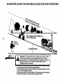
II. SLOPE OPERATION
Slopesare a majorfactor relatedto loss-of-controland tipover
accidents,whichcan resultin severe injuryor death. All slopes
requireextracaution.If youcannotbackup theslopeor ifyoufeel
uneasy on it, do not mow it.
DO:
•
•
•
•
•
•
•
Mow up and down slopes, not across.
Remove obstacles such as rocks, tree limbs, etc.
Watch for holes, ruts, or bumps. Uneven terrain could
overturn the machine. Tall grass can hide obstacles.
Use slow speed. Choose a low gear sothat you will not
have to stop or shift while on the slope.
Follow the manufacturer's recommendations for wheel
weights or counterweights to improve stability.
Use extra care with grass catchers or other attachments. These can change the stability of the machine.
Keep all movementon the slopesslowand gradual Do not
make sudden changes in speed or direction.
Avoidstartingor stoppingon a slope. If tires lose traction,
disengagethe bladesand proceedslowlystraightdownthe
slope.
2
DO NOT:
•
Do not turn on slopes unless necessary, and then, turn
slowly and gradually downhill, if possible.
•
Do not mow near drep-offs, ditches, or embankments.
The mower could suddenlytum over ifawheel isover the
edge of a cliff or ditch, or if an edge caves in.
•
Donotmow on wet grass. Reduced traction couldcause
sliding.
•
Do not try to stabilize the machine by putting your foot
on the ground.
•
Do not use grass catcher on steep slopes.
III. CHILDREN
Tragic accidents can occur ifthe operator is not alert to the
presence of children. Children are often attracted to the
machine and the mowing activity. Never assume that
children will remain where you last saw them.
•
Keep children out of the mowing area and under the
watchful care of another responsible adult.
•
Be alert and turn machine off if children enter the area.
•
Before and when backing, look behind and down for
small children.
•
Nevercarrychildren. TheymayfaUoffandbeseriously
injured or interfere with safe machine operation.
•
Never allow children to operate the machine.
•
Use extracare when approaching blindcomers, shrubs,
trees, or other objects that may obscure vision.
IV. SERVICE
•
•
•
•
•
•
•
•
•
•
Use extra care in handling gasoline and other fuels.
They are flammable and vapors are explosive.
- Use only.an approved container.
- Never remove gas cap or add fuel with the engine
running. Allow engine to cool before refueling. Do not
smoke.
- Never refuel the machine indoors.
- Never storethe machine or fuel containerinsidewhere
there is an open flame, such as a water heater.
Never run a machine inside a closed area.
Keep nuts and bolts, especially blade attachment bolts,
tight and keep equipment in good condition.
Never tamper with safety devices. Check their proper
operation regularly.
Keep machine free of grass, leaves, or other debris
build-up. Clean oilorfuel spillage. Allowmachine tocool
before storing.
Stop and inspect the equipment ifyou strike an object.
Repair, if necessary, before restarting.
Never make adjustments or repairs with the engine
running.
Grass catcher components are subject to wear, damage, and deterioration,which couldexpose movingparts
or allow objects to be thrown. Frequently check components and replace with manufacturer's recommended
parts, when necessary.
Mower blades are sharp and can cut. Wrapthe blade(s)
or wear gloves, and use extra caution when servicing
them.
Check brake operation frequently. Adjust and service
as required.
SAFETY RULES
&
Safe Operation Practices for Ride-On Mowers &
Be sure the area is clear of other people before mowing. Stop
machine if anyone enters the area.
Never carry passengers or children even with the blades off.
Do not mow in reverse unless absolutely necessary. Always
look down and behind before and while backing.
Never carry children. They may fail off and be seriously
injured or interfere with safe machine operation.
Keep children out ofthe mowing area and under the watchful
care of another responsible adult.
Be alert and turn machine off it children enter the area.
Look for this symbol to point out important
safety precautions.
It means CAUTIONIfl
BECOME ALERT!!I
YOUR SAFETY IS INVOLVED.
CAUTION:
Do not coast down a hill in
neutral, you may lose control of the tractor.
Before and when backing, look behind and down for small
children.
CAUTION: Tow only the attachments that
are recommended
by and comply with
specifications of the manufacturer of your
tractor. Use common sense when towing.
Operate only st the lowest possible speed
when on a slope. Too heavy of a load, while
on a slope, is dangerous. Tires can lose
traction with the ground and cause you to
lose control of your tractor.
Mow up and down slopes (15° Max), not across.
Remove obstacles such as rocks, tree limbs, etc.
Watch for holes, ruts, or bumps. Uneven terrain could overturn the machine. Tall grass can hide obstacles.
Usa slow speed. Choose a lowgear so that you will not have
to stop or shift while on the slope.
Avoid starting or stopping on a slope. If tires lose traction,
disengage the blades and proceed slowly straight down the
slope.
If machine stops while going uphill, disengage blades, shift
into reverse and back down slowly.
Do not tum on slopes unless necessary, and then, turn slowly
and gradually downhill, if possible.
A
CAUTION: In order to prevent accidental
starting when setting up, transporting, adjusting or making repairs, always disconnect spark plug wire and place wire where
it cannot contact spark plug.
TABLE OF CONTENTS
;AFETY RULES ........................................................
2-3
)RODUCT SPECIRCATIONS ....................................... 4
VARRANTY ..................................................................
4
-'USTOMER RESPONSIBILmES ...................... 4, 15-18
_.SSEMBLY ................................................................
6-8
)PERATION .............................................................
9-14
MAINTENANCE SCHEDULE .......................................
15
SERVICE AND ADJUSTMENTS ............................. 19-23
STORAGE ...................................................................
24
TROUBLESHOOTING .............................................
25-26
REPAIR PARTS - TRACTOR .................................. 28-43
REPAIR PARTS - ENGINE ...................................... 44-51
PARTS ORDERING/SERVICE ................. BACK COVER
PRODUCT
SPECIFICATIONS
CONGRATULATIONS on yourpurchaseof anewtractor. It
has been designed, engineered and manufactured to give
you the best possible dependability and performance.
GASOLINE CAPACITY
AND TYPE:
1.25 GALLONS
UNLEADED REGULAR
OILTYPE (API-SF-SJ):
SAE 10W30 (above 32°F)
SAE 5W-30 (below 32°F)
OIL CAPACITY:
4.5 PINTS
SPARK PLUG:
GAP: .030")
CHAMPION
RC12YC
Please read and retain this manual. The instructions will
enable you to assemble and maintain your tractor properly.
Always observe the =SAFETY RULES'.
GROUND SPEED (MPH):
FORWARD:
REVERSE:
5.5
2.4
MAINTENANCE
TIRE PRESSURE:
FRONT:
REAR:
CHARGING SYSTEM:
15 AMPS @ 3600 RPM
CUSTOMER
BA'I-rERY:
AMP/HR:
MIN. CCA:
CASESIZE:
•
•
Read and observe the safety rules.
Follow a regular schedule in maintaining, caring for and
using your tractor.
BLADE BOLT TORQUE:
27-35 FT. LBS.
•
Follow the instructions under =Customer Responsibilities" and =Storage" sections of this owner's manual.
Should you experience any problem you cannot easily
remedy, please contact your nearest authorized service
center/department. We have competent, well-trained technicians and the proper tools to service or repair this tractor.
AGREEMENT
A Maintenance Agreement is available on this product.
Contact your nearest Seare store for details.
14 PSi
10 PSI
28
230
UlR
RESPONSIBILITIES
WARNING: This tractor is equipped with an internal combustion engine and should not be used on or near any
unimproved forest-covered, brush-covered or grass-covered land unless the engine's exhaust system is equipped
with a spark arrester meeting applicable local or state laws
(if any). If a spark an'ester is used, it should be maintainecl
in effective working order by the operator.
A spark arrester for the muffler is available through your
nearest authorized service center/department (See REPAIR PARTS section of this manual).
WARRANTY
LIMITED
TWO (2) YEAR WARRANTY
ON CRAFTSMAN
TRACTOR
(RIDING
EQUIPMENT)
For two (2) years from date of purchase Sears Canada, Inc. will repair or replace at Sears option free of charge parts which
are defective as a result of material or workmanship.
FULL ONE (1) YEAR WARRANTY ON BATTERY
For one (1) year from date of purchase, if any battery included with this riding equipment proves defective in material or
workmanship and our testing determines the battery will not hold a charge, Sears will replace the battery at no charge.
COMMERCIAL OR RENTAL USE
Warranty on Riding Equipment used for commercial or rental purposes is limited to ninety (90) days.
This Warranty does NOT cover:
1. Pre.delivery set-up.
2. Tire replacement or repair caused by punctures from outside objects (such as nails, thoms, stumps, or glass).
3. Expendable items which become worn during normal use, such as blades, spark plug, air cleaners and belts.
4. Repairs necessary because of operator abuse or negligence, including damaged jackshaft or mandrel and the
failure to operate and maintain the equipment according to the instructions contained in the Owner's Manual.
5. In Home service.
Warranty service is available by returning the Craftsman Riding Equipment to the nearest Sears Service Centre/Department in
Canada. This warranty applies only while this product is in use in Canada.
This warranty is in addition to any statutory warranty and does not exclude or limit legal dghts you may have but shall run
concurrently with applicable provincial legislation. Furthermore, some provinces do NOT allow limitation on how long an
implied warranty will last so the above limitations may not apply to you.
SEARS CANADA, INC., TORONTO, ONTARIO M5B 2138
4
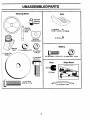
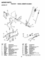
UNASSEMBLED PARTS
Steering
Wheel
Seat
_
Premium
Steering
Adapter
(1) Washer
17132 x 1-3/16 x 12 Gauge
Extension
Shaft
t
Steedng
(1) Knob
Steering
Wheel Insert
Steering
Boot
(1) Large Flat
Washer
@@
BaRery
(1) Lockwasher 318 (1) Locknut
5/16-1 8
(2) Hex Bolts 1/4-20 x 3/4
(1) Hex Bolt
3/8-16 x 1
Keys
(2) Keps Nuts 1/4-20
Slope Sheet
(2) Keys
5/16-18 x 1-1/4
(1) Hex Bolt
(1) Oil Drain Tube
5
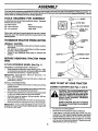
ASSEMBLY
Your new tractor has been assembled at the factory with exception of those parts left unassembled for shipping purposes. To
ensure safe and proper operation of your tractor all parts and hardware you assemble must be tightened securely. Usa the
correct tools as necessary to insure proper tightness.
TOOLS
REQUIRED
FOR ASSEMBLY
L"_
INSERT
A socket wrench set will make assembly easier. Standard
wrench sizes are listed.
(1) 9/16" wrench
Pliers
(2) 7/16" wrenches
(2) 1/2"wrenches
_=---.---5/8LOCK
Tire pressure gauge
Utility knife
_"_'_.-
When right or left hand is mentioned inthis manual, itmeans
when you are in the operating position (seated behind the
steedng wheel).
WASHER
LARGE FLAT
STEERING_
wASHER
WHEEL
TO REMOVETRACTOR
UNPACK
•
•
•
FROM CARTON
•=
STEERING
_TABS':
BOOT
CARTON
Remove all accessible loose parts and parts cartons
from carton.
Cut, from top to bottom, along lines on all four corners
of carton, and lay panels flat.
Check for any additional loose parts or cartons and
remove.
ADAPTER
BEFORE REMOVING
SKID
ATTACH
STEERING
TRACTOR
WHEEL
EXTENSION
SHAFT
FROM
5/16
LOCKNUT _
5/16 HEX BOLT
(See Fig. 1)
ASSEMBLE EXTENSION SHAFT AND BOOT
•
Slide extension shaft onto lower steering shaft. Align
mounting holes in extension and lowershafts and install
5/16 hex bolt and Iocknut. Tighten securely.
IMPORTANT: TIGHTEN BOLT AND NUT SECURELY TO
18-22 FT. LBS TORQUE.
•
_
t
t
I
f
I
Place tabs of steedng boot over tab slots in dash and
push down to secure.
FIG. 1
INSTALL STEERING WHEEL
HOW TO SET UP YOUR TRACTOR
•
Position front wheels of the tractor so they are pointing
straightforward.
•
Remove steering wheel adapter from steedng wheel and
slide adapter onto steering shaft extension.
•
Position steering wheel so cross bars are horizontal (left
to right) and slide inside boot and onto adapter.
•
Assemble large flat washer, 318 lock washer, 3/8 hex
bolt and tighten securely.
Snap steedng wheel insert into center of steedng wheel.
•
Remove protective materials from tractor hood and grill.
IMPORTANT: CHECK FOR AND REMOVE ANY STAPLES
IN SKID THAT MAY PUNCTURE TIRES WH ERE TRACTOR
IS TO ROLL OFF SKID.
CONNECT
_
BATTERY
(See Figs. 2 and 3)
nals by allowing a wrench or any other
object to contact both terminals at the
CAUTION: Do not short battery termisame time. Before connecting battery,
remove metal bracelets, wristwatch
bands, rings, etc.
Positive terminal must be connected
first to prevent sparking from accidental
grounding.
Lift seat pan to raised position.
Remove terminal protective caps and discard.
If this battery is put into service after month and year
indicated on label (label located between terminals)
charge battery for minimum of one hour at 6-10 amps.
Firstconnect RED battery cable to positive (+) terminal
with hex bolt and keps nut as shown. Tighten securely.
Slide terminal cover over terminal.
6
ASSEMBLY
Connect BLACK groundingcable to negative (-) terminal
with remaining hex bolt and keps nut. Tighten securely.
DISCARD
SEAT
TERMINAL
PROTECTIVE
CAPS
SEAT
KEPS
TERMINAL
!i
HEX BOLT
NU_
PAN_
POSITIVE
CABLE
(BED)
NEGATIVE
CABLE
SHOULDER
BOLTS
(BLACK)
FLAT
WASHER
RG. 2
SEAT PAN
ADJUSTMENT
KNOB
m
W
FIG. 4
NOTE: You may now roll or ddve your tractor off the skid.
Follow the appropriate instruction below to remove the
tractor from the skid.
TO ROLL TRACTOR OFF SKID (See Operation
section page 10 for location
controls)
FIG. 3
NSTALL
SEAT
(See
Press liftlever plunger and raise attachment liftlever to
its highest position.
•
Release parkingbrake bydepressing clutctVorakepedal.
•
Place freewheel control in freewheeling position to
disengage transmission (See "TO TRANSPOR'I" inthe
Operation section of this manual).
Roll tractor forward off skid.
•
Pivot seat upward and remove from the cardboard
packing. Remove the cardboard packing and discard.
Place seat on seat pan so head of the shoulder boltsare
positioned over large slotted holes in pan.
Push down on seat to engage shoulder boltsin slots and
pull seat towards rear of tractor.
Pivot seat and pen forward and assemble adjustment
knob end flat washer loosely. Do not tighten.
Lower seat into operating position and sit on seat.
Slide seat until a comfortable position is reached which
allows you to press clutch/brake pedal all the way down.
Get off seat without moving its adjusted position.
Raise seat and tighten adjustment knob securely.
of
•
Fig. 4)
\d just seat before tightening adjustment knob.
Remove adjustment knob and flatwasher securing seat
to cardboard packing and set aside for assembly of seat
to tractor.
and function
•
Remove banding holding deflector shield up against
tractor.
TO DRIVE TRACTOR OFF SKID (See Operation section page 10 for location and function
of controls)
_WARNING:
Before starting, read, understand and follow
all instructions in the Operation section of this manual. Be
sure tractor is in a well-ventilated area. Be sure the area in
front of tractor is clear of other people and objects.
•
Be sure all the above assembly steps have been
completed.
•
•
Check engine oil level and fillfuel tank with gasoline.
Place freewheel control in "transmission engaged" position.
•
Sit on seat in operating position, depress clutch/brake
pedal and set the parking brake.
Place motion control lever in neutral (N) position.
•
7
ASSEMBLY
Press lift lever plunger and raise attachment lift lever to
its highest position.
Start the engine. After engine has staded, move throttle
control to idle position.
Release parking brake.
Slowly move the motion contmlleverforward and slowly
drive tractor off skid.
CHECK
BELTS
Apply brake to stop tractor, set parking brake and place
motion control lever in neutral position.
•
Turn ignition key to "OFF" position.
Continue with the instructionsthat follow.
CHECK
•
•
•
•
BEFORE YOU OPERA TEAND ENJO Y YOUR NEW TRAC
TOR, WE WISH TO ASSURE THAT YOU RECEIVE THI
BEST PERFORMANCEAND SATISFACTION FROM 7741.
QUALITY PRODUCT.
Raise and hold deflector shield in upright position.
Place front of mulcher plate over front of mower deck
opening and slide into place, as shown,
Hook front latch into hole on front of mower deck.
Hook rear latch into hole on back of mower deck.
PLEASE REVIEW THE FOLLOWING CHECKLIST:
/
,/
,/
All assembly instructions have been completed.
No remaining loose parts in carton.
Batteryisproperiypreparedandcharged.
(Minimurr
hour at 6 amps).
,/
Seat is adjusted comfortably and tightened securely
/
All tires are properly inflated. (For shipping purpose
the tires were overinflated at the factory).
,/ Be sure mower deck is propedy leveled side-to-si_
frent-to-rear for best cutting results. (Tires must b
properly inflated for leveling).
4" Checkmoweranddrivebelts.
Besuretheyareroute
properly around pulleys and inside all belt keepers.
,/ Checkwiring. See that all connections are still secur_
and wires are properly clamped.
,,I Before driving tractor, be sure freewheel control is in
drive position.
WHILE LEARNING HOW TO USE YOUR TRACTOR, PAY
EXTRA A TTENTION TO THE FOLLOWING IMPORTANT
ITEMS:
CAUTION: Do not remove deflector shield
from mower. Raise and hold shield when
attaching mulcher plate and allow it to
rest on plate while in operation.
MULCHER
PLATE
LATCH
HOOKS
/
/
FIG. 5
TO CONVERT TO BAGGING OR
DISCHARGING
/
Simply remove mulcher plate and store in a safe place. Your
mower isnow ready for discharging or installation ofoptional
grass catcher accessory.
NOTE: It is not necessary to change blades. The muicher
blades are designed for discharging and bagging also.
CHECK
TIRE
/
,/
PRESSURE
The tires on your tractor were overinflated at the factory for
shipping purposes. Correct tire pressure is important for
best cutting performance.
•
Reduce tire pressure to PSI shown in =PRODUCT
SPECIFICATIONS" section of this manual.
CHECK
DECK
SYSTEM
,/CHECKLIST
OfpreWou. yremoved)
(SeeF j. 5)
DEFLECTOR
SHIELD
BRAKE
Afteryou learn howto operate yourtractor, checktoseethat
the brake is properly adjusted. See "TO ADJUST BRAKE"
in the Service and Adjustments section of this manual.
INSTALL MULCHEFI PLATE
•
•
OF ALL
See the figures that are shown for replacing motion and
mower blade drive belts in the Service and Adjustments
section of this manual. Verify that the belts are routed
correctly.
•
•
•
FOR PROPER POSITION
LEVELNESS
For best cutting results, mower housing should be properly
leveled. See "TO LEVEL MOWER HOUSING" inthe Service
and Adjustments section of this manual.
8
Engine oil is at proper level.
Fuel tank is filled with fresh, clean, regular unleaded
gasoline.
Become familiar with all controls - their location and
function. Operate them before you start the engine.
Be sure brake system is in safe operating condition.
It is important to purge the transmission before operating
your tractor for the first time. Follow proper starting and
transmission purging instructions (See =TO START
ENGINE" and "PURGE TRANSMISSION" in the Operation section of this manual).
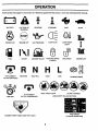
OPERATION
l'hese symbols may appear on your tractor or in literature supplied with the product, Learn and understand their meaning.
BATTERY
CAUTION OR
WARNING
REVERSE
FORWARD
FAST
SLOW
ENG,N_ON
ENG,NEOFF
O,'PRESSORE
L,G._SO.OVE_MP 1"
FUEL
CHOKE
MOWER HEIGHT
PARKING BRAKE
LOCKED
UNLOCKED
MOWER LIFT
N H
A'I-rACHMENT
CLUTCH ENGAGED
IGNITION
REVERSE
NEUTRAL
ATTACHMENT
CLUTCH DISENGAGED
HIGH
LOW
KEEP AREA CLEAR
PARKING BRAKE
SLOPE HAZARDS
(SEE SAFETY RULES SECTION)
FREE WHEEL
(Automatic Models only)
DANGER, KEEP HANDS AND FEET AWAY
9
OPERATION
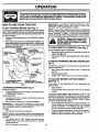
KNOW YOUR TRACTOR
READ THIS OWNER'S
MANUAL
AND SAFETY
RULES
BEFORE
OPERATING
YOUR TRACTOR
Compare the illustrationswith you r tractor to familiarize you meffwith the locations of various controlsand adjustments. Save
this manual for future reference.
AIT'ACHMENT
CLUTCH LEVER
IGNITION
SWITCH
AMMETER
LIGHT
SWITCH
POSITION
UFTLEVER
PLUNGER
THROTTL_
CHOKE
CONTROL
ATTACHMENT
CLUTCH/
BRAKE
PEDAL
HEIGHT
ADJUSMENT
PARKING
BRAKE
FREE WHEEL
CONTROL
MOTION
CONTROL
LEVER
SPEED
3MPH
2MPH
1MPH
\
FIG. 6
Our tractors conform to the safety standards of the Amedcan National Standards Institute.
ATrACHMENT CLUTCH LEVER: Used to engage the
mower blades, orotherattachments mounted to yourtractor.
LIGHT SWITCH POSITION: Turns the headlights on and
off.
AMMETER: Indicates charging (+) or discharging (-) of
battery.
MOTION CONTROL LEVER:
Selects the speed and
direction of tractor.
THROTrLFJCHOKE CONTROL:
Used for starting and
controllingengine speed.
CLUTCH/BRAKE PEDAL: Used for declutching and braking the tractor and starting the engine.
PARKING BRAKE: Locks clutch/brake pedal intothe brake
position.
FREEWHEEL CONTROL: Disengages transmission for
pushing or slowly towing the tractor with the engine off.
A'B'ACHMENT LIFT LEVER: Used to raise, lower, and
adjustthe mower deck orother attechments mounted toyour
tractor,
LIFT LEVER PLUNGER: Used to release attachment lift
lever when changing its position.
IGNITION SWITCH: Used for starting and stopping the
engine.
10
OPERATION
The operetlon of any tractor can msuit In foreign objectsthrown Into the eyes, which can
result in severe eye damage. Always wear safety glasses or eye shields whila operating
your tractor or performing any adjustments or repairs. We recommend a wide vision
safety mask over spectacles or standard safety glasses.
IMPORTANT: LEAVING THE IGNITION SWITCH IN ANY
POSITION OTHER THAN "OFF" WILL CAUSE THE
BATTERY TO BE DISCHARGED, (DEAD).
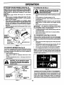
HOW TO USE YOUR TRACTOR
TO SET PARKING
BRAKE
(See Fig. 7)
You rtractor isequipped with an operator presence sensing
switch. When engine is running, any attempt bythe operator
to leave the seat without first setting the parking brake will
shut off the engine.
•
Depress clutch/brake pedal into full "BRAKE" position
and hold.
•
NOTE: Under cerlain conditionswhen tractoris standing idle
with the engine running, hot engine exhaust gases may
cause "browning" of grass. To eliminate this possibility,
always stop engine when stopping tractor on grass areas.
Place parking brake lever in =ENGAGED" position and
release pressure from clutch/brake pedal. Pedal should
remain in =BRAKE" position. Make sure parking brake
will hold tractor secure.
THROTTLE]
CHOKE CONTR
PARKING BRAKE
"ENGAGED"
POSITION
\
]_lk
TO USE THROI-rLE
ATTACHMENT
CLUTCH LEVER
"ENGAGED"
pletely, as described above, before leaving the operetor's position; to empty
AUTION:
Always
grass
catcher,
etc. stop tractor com-
CONTROL
I
(See Fig. 7)
Always operate engine at full throttle.
•
Operating engine at less than full throttle reduces the
battery charging rate.
•
Full throttle offers the best bagging and mower performance.
POSITION
1
TO MC
MOVE
"BRAKE"
FORWARD
AND
BACKWARD
(See
Fig. 7)
"I
The
direction and speed of movement is controlled by the
motion control lever.
n
•
•
TO ADJUST
DLUT RAKE
,EDALARKI.G
eRAKE
"DRIVE"
PosmoN
"DISENGAGED"
(See Fig. 7)
Tostop mower blades,move attachmentclutch
"DISENGAGED" position.
GROUND DRIVE-
leverto
To stop ground ddve, depress clutch/brake pedal into
full "BRAKE" position.
Move motion control lever to neutral (N) position.
IMPORTANT:
THE MOTION CONTROL LEVER DOES
NOT RETURN TO NEUTRAL (N) POSITION WHEN THE
CLUTCH/BRAKE PEDAL IS DEPRESSED.
ENGINE Move throttle control to slow position.
NOTE: Failure to move throttle control to slow position and
allowing engine to idle before stopping may cause engine to
"backfire".
Turn ignition key to =OFF" position and remove key.
Always remove key when leaving tractor to prevent
unauthorized use.
•
Never use choke to stop engine.
HEIGHT
Thecutting height rangeis approximately 1-1/2to 4". The
heights are measured from the ground to the blade tip with
the engine not running. These heights are approximate and
may vary depending upon soil conditions, height of grass
and types of grass being mowed.
•
The average lawn shouid be cutto approximately 2-1/2
inches during the cool season and to over 3 inches
during hot months. For healthier and better looking
lawns, mow often and after moderate growth.
•
For best cutting performance, grass over 6 inches in
height should be mowed twice. Make the first cut
relatively high; the second to desired height.
•
•
CU'I-rlNG
The position of the attachment lift lever determines the
cutting height.
•
Grasp lift lever.
•
Press plunger with thumb and move lever to desired
position.
MOWER BLADES •
MOWER
(See Fig. 7)
POSITION
FIG. 7
STOPPINGSTOPPING
Start tractor with motion control lever in neutral (N)
position.
Release parking brake.
Slowly move motion control lever to desired position.
11
OPERATION
TO ADJUST
GAUGE
WHEELS
(See Fig. 8)
TO OPERATE
Gauge wheels are propedy adjusted when they are slightly
off the ground when mower isat the desired cutting height in
operating position. Gauge wheels then keep the deck in
proper position to help prevent scalping in most terrain
conditions.
NOTE:Adjust gauge wheels with tractor on a flat level
surface.
•
Adjust mower to desired cutting height (See rl'O ADJUST MOWER CU'I-rING HEIGHT" in the Operation
section of this manual).
•
With mower in desired height of cut position, gauge
wheels should be assembled so they are slightlyoff the
ground. Install gauge wheel in appropriate hole with
shoulder bolt, 3/8 washer, and 3/8-16 Iocknut and tighten
securely.
•
Repeat for opposite side installinggauge wheel in same
adjustment hole.
ON HILLS
with slopes greater than 15 ° and do not
AUTION:
drive
acrossDonotdriveupordownhills
any slope.
I_IL
I
•
Choose the slowest speed before starting up or down
hills.
•
•
Avoid stopping or changing speed on hills.
If slowing is necessary, move throttle control lever to
slower position.
If stopping is absolutely necessary, push clutch/brake
pedal quickly to brake position and engage parking
brake.
•
•
Move motion control lever to neutral (N) position.
IMPORTANT:
THE MOTION CONTROL LEVER DOES
NOT RETURN TO NEUTRAL (N) POSITION WHEN THE
CLUTCH/BRAKE PEDAL IS DEPRESSED.
•
•
•
To restart movement, slowly release parking brake and
clutch/brake pedal.
Slowly move motion control lever to slowest setting.
Make all turns slowly.
TO TRANSPORT
(See Figs. 6 and 10)
When pushing or towing your tractor, be sure to disengage
transmission by placing freewheel control in freewheeling
position. Free wheel control islocated at the rear drawbar of
tractor.
•
•
FIG. 8
•
•
TO OPERATE
MOWER
(See Fig. 9)
Your tractor is equipped with an operatorpresence sensing
switch. Any attempt by the operator to leave the seat with
the engine running and the attachment clutch engaged will
shut off the engine.
•
Select desired height of cut.
•
Start mower blades by engaging attachment clutch
control.
•
TO STOP MOWER BLADES - disengage attachment
clutch control.
Raise attachment liftto highest posifionwith attachrnent
lift control.
Pull freewheel control out and down into the slot and
release so it is held in the disengaged position.
Do not push or tow tractor at more than two (2) MPH.
To reengagetransmission, reverseabove procedure.
NOTE: To protecthoodfrom damage when transportingyour
tractor on a truck or a trailer, be sure hood is closed and
secured to tractor. Use an appropriate means oftying hood
to tractor (rope, cord, etc.).
CAUTION: Do not operate the mower
without either the entire grass catcher,
ORmowers so equipped, or the deflector
shield in place.
"ENGAGED"
POSITION
_
_
_=_/r_
/
ATTACHMENT
LIFT LEVER
HIGH POSITION
FIG. 10
POSiT,ON TOWING
POSITION
_
,//
Tow only the attachments that are recommended by and
comply with specifications of the manufacturer of your
tractor. Use common sense when towing. Too heavy of a
load, while on a slope, is dangerous. Tires can lose traction
with the ground and cause you to lose controlofyour tractor.
) )_"_DEFLECTOR
/
_
SHIELD
FIG. 9
CARTS AND OTHER ATTACHMENTS
12
OPERATION
BEFORE
STARTING
THE ENGINE
Insert key into ignition and tum key clockwise to
=START" position and release key as soon as engine
starts. Do not run starter continuously for more than
fifteen seconds per minute. If the engine does not start
after several attempts, move throttle control to fast
position,wait a few minutes and try again. If engine still
does not start, move the throttle control back to the
choke position and retry.
CHECK
•
•
•
•
•
ENGINE
OIL LEVEL
The engine in your tractor has been shipped, from the
factory, already filled with summer weight oil.
Check engine oil with tractor on level ground.
Unthreed and remove oil fill cap/dipstick; wipe oil off.
Reinsert the dipstick intothe tube and rest oil fill cap on
the tube. Do not thread the cap onto the tube. Remove
and read oil level. If necessary, add oil until =FULL"
mark on dipstick is reached. Do not overfill.
For cold weather operation you should change oil for
easier starting (See "OIL VISCOSITY CHART" in the
Customer Responsibilities section of this manual).
To change engine oil, see the Customer Responsibilities section in this manual.
WARM WEATHER STARTING (50 ° F and above)
•
When engine starts, move the throttle controltothe fast
position.
•
The attachments and ground drive can now be used. If
the engine does not accept the load, restart the engine
and allow it to warm up for one minute using the choke
as described above.
COLD WEATHER STARTING ( 50 ° F AND BELOW)
•
When engine starts, allow engine to run with thethrottle
control in the choke position until the engine runs
roughly, then move throttle control to fast position. This
may require an engine warm-up peried from several
seconds to several minutes, depending on the temperature.
ADD GASOLINE
•
Fill fuel tank. Use fresh, clean, regular unleaded
gasoline with a minimum of 87 octane. (Use of leaded
gasoline will increase carbon and lead oxide deposits
and reduce valve life). Do not mix oil with gasoline.
Purchase fuel in quantities that can be used within 30
days to assure fuel freshness.
IMPORTANT: WHEN OPERATING IN TEMPERATURES
BELOW 32°F(0°C), USE FRESH, CLEAN WINTER GRADE
GASOLINE TO HELP INSURE GOOD COLD WEATHER
STARTING.
AUTOMATIC TRANSMISSION WARM UP
•
Before ddvingthe unit in cold weather, the transmission
should be warmed up as follows:
• Be sure the tractor is on level ground.
• Place the motion control lever in neutral.
Release
the parking brake and let the clutch/brake s I o w I y
return to operating position.
• Allow one minute for transmission to warm up. This
can be done during the engine warm up pedod.
•
The attachments can also be used dudng the engine
warm-up periodafterthe transmissionhas been warmed
up.
WARNING: Experience indicatesthat alcohol blended fuels
(called gasohol or using ethanol or methanol) can attract
moisture which leads to separation and formation of acids
during storage. Acidic gas can damage the fuel system of
an engine while in storage. To avoid engine problems, the
fuel system should be emptied before storage of 30 days or
longer. Drain the gastank, startthe engine and let itrun until
the fuel lines and carburetor are empty. Use fresh fuel next
season. See Storage Instructionsforadditional information.
Never use engine or carburetor cleaner products in the fuel
tank or permanent damage may occur.
CAUTION: Fill to bottom of gas tank
filler neck. Do not overfill. Wipeoffany
spilled oil or fuel. Do not store, spill or
use gasoline near an open flame.
TO START ENGINE
NOTE: If at a high altitude (above 3000 feet) or in cold
temperatures (below 32 F) the carburetor fuel mixture may
need to be adjusted for best engine performance. See "TO
ADJUST CARBURETOR" in the Service and Adjustments
section of this manual.
I
I
(See Fig. 6)
PURGE
[_lb
When starting the engine for the firsttime or ifthe engine has
run out of fuel, it will take extra cranking time to move fuel
from the tank to the engine.
•
Besure freewheelcontrol isinthe transmission engaged
position.
Sit on seat in operating position, depress clutch/brake
pedal and set parking brake.
•
Place motion control lever in neutral (N) position.
•
Move attachment clutch to =DISENGAGED" position.
Move throttle control to choke position.
TRANSMISSION
freewheel lever while the engine is runAUTION: Neverengageordisengage
ning.
I
To ensure proper operation and performance, it is recom-.
mended that the transmission be purged before operating
tractor for the first time. This procedure will remove any
trapped air inside the transmission which may have beveloped during shipping of your tractor.
IMPORTANT: SHOULD YOUR TRANSMISSION REQUIRE
REMOVAL FOR SERVICE OR REPLACEMENT,
IT
SHOULD BE PURGED AFTER REINSTALLATION BEFORE
OPERATING THE TRACTOR.
Place tractor safely on level surface with engine off and
parking brake set.
•
Disengage transmission by placing freewheelcontrol in
freewheeling position (See "TO TRANSPORT" in this
section of manual).
NOTE: Before starting, read the warm and cold starting
procedures below.
13
OPERATION
•
•
Sitting in the tractor seat, start engine. After the engine
is running, move throttle control to slow position. With
motion control lever in neutral (N) position, slowly
disengage clutch/brake pedal.
Move motion control lever to full forward position and
hold for five (5) seconds. Move lever to full reverse
position and hold for five (5) seconds. Repeat this
procedure three (3) times.
NOTE: During this procedure there will be no movement of
drive wheels. The air is being removed from hydraulic drive
system.
•
Move motion control lever to neutral (N) position. Shutoff engine and set parking brake.
•
Engage transmission by placing freewheel control in
driving position (See "TO TRANSPORT" in this section
of manual).
•
•
•
•
•
•
•
•
•
•
MULCHING
MOWING
TIPS
IMPORTANT: FOR BEST PERFORMANCE, KEEP MOWER
HOUSING FREE OF BUILT-UP GRASS AND TRASH.
CLEAN AFTER EACH USE.
Sitting in the tractor seat, start engine. After the engine
is running, move throttle controlto half (112) speed. With
motion control lever in neutral (N) position, slowly
disengage clutch/brake pedal.
Slowly move motion control lever forward, after the
tractor moves approximately five (5) feet, slowly move
motion control leverto reverse position. After the tractor
moves approximately five (5) feet return the motion
control lever to the neutral (N) position. Repeat this
procedure with the motion control lever three (3) times.
Your tractor is now purged and now ready for normal
operation.
MOWING
•
RG. 11
•
•
TIPS
•
Mower should be propedy leveled for best mowing
performance. See =TO LEVEL MOWER HOUSING" in
the Service and Adjustments section of this manual.
The lefthand side of mower shouldbe used for trimming.
Drive so that clippings are discharged ontothe area that
has been cut. Have the cut area to the right of the
machine. This will result in a more even distribution of
clippings and more uniform cutting.
When mowing large areas, start bytuming to the right so
that clippings will discharge away from shrubs, fences,
driveways, etc. After one or two rounds, mow in the
opposite direction making left hand turns until finished
(See Fig. 11).
If grass is extremely tall, it should be mowed twice to
reduce load and possible fire hazard from dried clippings. Make first cut relatively high; the second to the
desired height.
•
•
The special mulching blade willrecut the grassclippings
many times and reduce them in size so that as they fall
onto the lawn they willdisperse intothe grass and notbe
noticed. Also, the mulched grass will biodegrade
quickly to provide nutrientsfor the lawn. Always mulch
with your highest engine (blade) speed as this will
provide the best recutting action of the blades.
Avoid cutting your lawn when it iswet. Wet grass tends
to form clumps and interferes with the mulching action.
The best time to mow your lawn isthe early afternoon.
At this time the grass has dried and the newly cut area
will not be exposed to the direct sun.
For best results, edjust the mower cutting height so that
the mower cuts off only the top one-third of the grass
blades (See Fig. 12). For extremely heavy mulching,
reduce your width of cut on each pass and mow slowly.
Certain types of gress and grass conditionsmay require
that an area be mulched a second time to completely
hide the clippings. When doing a second cut, mow
across or perpendicular to the first cut path.
Change your cutting pattern from week to week. Mow
north to south one week then change to east to west the
next week. This will help prevent matting and graining
of the lawn.
MAX 1/3
Do not mow grass when it is wet. Wet grass will plug
mowerand leave undesirable clumps. AIIowgrasstodry
before mowing.
Always operate engine at full throtUe when mowing
to assure better mowing performance and proper discharge of material. Regulate ground speed byselecting
a low enough gear to give the mower cutting performance as well as the quality of cut desired.
When operating attachments, select a ground speed
that willsuit the terrain and give best performance ofthe
attachment being used.
FIG. 12
14
CUSTOMER RESPONSIBILITIES
FILL IN DATES
REGULAR
C_e_
._f_"_.e_f'SERVICE
SERVICE
B-I_::; reO_atreiOn
Check Operator
Presence
_
and
R
Interlock Systems
Check for Loose Fasteners
C
Sharpen/Replace
Mower Blades
Lubrication Chart
_3
O
Check Battery Level
Clean Battery and Terminals
=_
1IV
Check Transexle
Check
E
;G
/
N
ik_s
9k_
!
Cooling
V-Belts
Check Engine Oi1 Level
Change
DATES
ll_
V'
Engine Oil (with oil filter)
Change Engine Oil (without oil filter)
Clean Air Filter
V_1,2
v'
b#_2
Clean Air Screen
Inspect Muffler/Spark
Replace
Arrester
I_'
Oil Filter (If equipped)
_,2
Clean Engine Cooling Fins
I_
Replace
Spark Plug
V
Replace
Air Filter Paper Cartridge
Replace
Fuel Filter
2
p
V _
I_
1 - Change more often when operating under a heavy load or
in high ambient temperatures.
2 - Service more often when operating in dirty or dusty conditions.
3 - Replace blades more often when mowing in sandy soil.
4 - Not required if equipped with maintenance-free battery.
5 - Tighten front axle pivot bolt to 35 ft.-Ibs, maximum.
Do not overtighten.
LUBRICATION
GENERAL
CHART
RECOMMENDATIONS
ZERK
The warranty on this tractor does not cover items that have
been subjected to operatorabuse or negligence. To receive
full value from the warranty, operator must maintain tractor
as instructed in this manual.
(1)FRONT
BEARING
ZERK
ZERK
"(_FRONT WHEEL
BEARING ZERK
Some adjustments will need to be made periodically to
properly maintain your tractor.
All adjustments in the Service and Adjustments section of
this manual should be checked at least once each season.
•
Once a year you should replace the spark plug, clean or
replace air filter, and check blades and belts forwear. A
new spark plug and clean air filter assure properair-fuel
mixture and helpyourengine run better and last longer.
BEFORE
•
•
•
•
•
EACH USE
Check engine oil level.
Check brake operation,
Check tire pressure.
Check operator prasenoe and
interlock systems for proper operation.
Check for loose fasteners.
(DGENERAL PURPOSE GREASE
(_REFER TO CUSTOMER RESPONSIBlUTIES
SECTION
15
"ENGINE"
IMPORTANT:
DO NOT OIL OR GREASE THE PIVOT POINTS
WHICH HAVE SPECIAL NYLON BEARINGS.
VISCOUS LUBRICANTS WILL ATTRACT DUST AND DIRT THAT WILL SHORTEN
THE LIFE OF THE SELF-LUBRICATING
BEARINGS.
IF YOU
FEEL THEY MUST BE LUBRICATED,
USE ONLY A DRY, POWDERED GRAPHITE
TYPE LUBRICANT
SPARINGLY.
CUSTOMER
RESPONSIBILITIES
TRACTOR
BRAKE
CENTER
HOLE
FLAT
LOC KWASHB_ _
WASHER ,_
J
TIRES
•
•
Maintain properair pressure in alltires (See =PRODUCT
SPECIFICATIONS" section of this manual).
Keep tires free of gasoline, oil, or insect control chemicals which can harm rubber.
_--_HEX
8)*
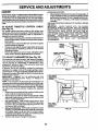
TO SHARPEN BLADE (See Fig. 14)
NOTE: We do not recommend sharpening blade- but ifyou
do, be sure the blade is balanced.
Care should be taken to keep the blade balanced. An
unbalanced blade will cause excessive vibration and eventual damage to mower and engine.
•
The blade can be sharpened with a file or on a grinding
wheel. Do not attempt to sharpen while on the mower.
•
To check blade balance, you will need a 5/8" diameter
steel bolt, pin, or a cone balancer. (When using a cone
balancer, follow the instructionssupplied with balancer).
SYSTEM
Be sure operator presence and interlock systems are working properly. If your tractor does not function as described,
repair the problem immediately.
•
The engine should not start unless the clutch/brake
pedal isfullydepressed and attachement clutch control
is in the disengaged position.
•
When the engine is running,any attempt bythe operator
to leave the seat without first setting the parking brake
should shut off the engine.
•
When the engine is runningand the attachment clutch is
engaged, any attempt by the operator to leave the seat
should shut off the engine.
•
The attachment clutch should never operate unlessthe
operator is in the seat.
BLADE
BOLT (GRADE
FIG. 13
NOTE: To seal tire punctures and prevent flat tires due to
slow leaks, tire sealant may be purchased from your local
parts dealer. Tire sealant also prevents tire dry rot and
corrosion.
PRESENCE
STAR
*A GRADE 8 HEAT TREATED BOLT CAN BE
IDENTIRED BY SIX UNES ON THE BOLT HEAD.
Avoid stumps, stones, deep ruts, sharp objects and
other hazards that may cause tire damage.
OPERATOR
ASSEMBLY
BLADE
OPERATION
Iftractor requires more than six (6) feet stopping distance at
high speed in highest gear, then brake must be adjusted.
(See =1O ADJUST BRAKE" in the Service and Adjustments
section of this manual).
•
MANDREL
TRAILING
UP
Always observe safety rules when performing any maintenance.
NOTE: Do not use a nail for balancing blade. The lobes of
the center hole may appear to be centered, but are not.
•
Slide blade on to an unthreaded portion of the steel bolt
or pinand hold the bolt or pin parallel with the ground. If
blade is balanced, it should remain in a horizontal
position. If either end of the blade moves downward,
sharpen the heavy end until the blade is balanced.
CENTER//
CARE
For best results mower blades must be kept sharp. Replace
bent or damaged blades.
5/8" BOLT
_
_.___,_-_
BLADE
BLADE
REMOVAL
(See Fig. 13)
•
Raise mower to highest position to allow access to
blades.
•
Remove hex bolt, Iockwasher and flat washer securing
blade.
•
Install new or resharpened blade with trailing edge up
towards deck as shown.
FIG. 14
BATTERY
Your tractor has a battery charging system which is sufficient for normal use. However, periodic charging of the
battery with an automotive charger will extend its life.
•
Keep battery and terminals clean.
•
Keep battery bolts tight.
•
Keep small vent holes open.
•
Rechargeat 6-10 amperes for I hour.
IMPORTANT: TO ENSURE PROPER ASSEMBLY, CENTER
HOLE IN BLADE MUST ALIGN WITH STAR ON MANDREL
ASSEMBLY.
•
Reassemble hex bolt, lock washer and flat washer in
exact order as shown.
•
Tighten bolt securely (27-35 Ft. Lbs. torque).
IMPORTANT:
BLADE BOLT IS GRADE 8 HEAT TREATED.
16
NOTE: The original equipment battery on your tractor is
maintenance free. Do not attempt toopen or remove caps or
covers. Adding or checking level of electrolyte is not
necessary.
CUSTOMER
RESPONSIBILITIES
TO CLEAN BATTERY AND TERMINALS
TO CHANGE ENGINE OIL (See Figs. 15 and 16)
Corresion and dirtonthe batteryand terminalscan cause the
battery to "leak" power.
•
Disconnect BLACK batterycable first then RED battery
cable and remove battery from tractor.
•
Rinse the battery with plain water and dry,
•
Clean terminals and battery cable ends with wire brush
until bright.
•
Coat terminals with grease or petroleum jelly.
•
Reinstall battery (See "CONNECT BAI-IERY" in the
Assembly section of this manual).
Determine temperature range expected before oil change.
All oil must meet API service classification SF-SJ.
•
Be sure tractor is on level surface.
•
Oil will drain more freely when warm.
•
Catch oil in a suitable container.
•
•
Remove oil fill cep/dipstick. Be careful not to allow dirt
to enter the engine when changing oil.
Remove yellowcap frem bottomfitting of drain valveand
install the drain tube onto the fitting.
OIL DRAIN VALVE
V-BELTS
Check V-belts for deterioration and wear after 100 hours of
operation and replace if necessary. The belts are not
adjustable. Replace belts if they begin to slip from wear.
TRANSAXLE
CLOSED
AND
POSITION
COOLING
The transmission fan and cooling fins should be kept clean
to assure proper cooling.
Do not attempt to clean fan or transmission while engine is
runningorwhile the transmission is hot.To prevent possible
damage to seals, do not use high pressure water or steam
to clean transaxle.
•
Inspect cooling fan to be sure fan blades are intact and
clean.
•
Inspect cooling fins for dirt, grass clippings and other
materials. To prevent damage to seals, do not use
compressed air or highpressure sprayer toclean cooling
fins.
TRANSAXLE
PUMP
TUBE
CAP
FIG. 16
FLUID
The transaxle was sealed at the factory and fluid maintenance is not required forthe life of the transaxle. Should the
transexle ever leakor require servicing,contact your nearest
authodzed service center/department.
•
Unlock drain valve by pushing inward and tuming counterclockwise.
•
•
To open, pull out on the drain valve.
Affer oilhas drained completely, close and Iockthe drain
valve by pushing inward and turning clockwise untilthe
pin is in the locked position as shown.
•
Remove the drain tube and replace the cap onto to the
bottom fitting of the drain valve.
Refill engine with oil through oil fill dipstick tube. Pour
slowly. Do not overfill. For approximate capacity see
"PRODUCT SPECIFICATIONS" sectionof this manual.
•
ENGINE
LUBRICATION
•
Only use high quality detergent oil rated with API service
classification SF-SJ. Select the oil's SAE viscosity grade
according to your expected operating temperature.
Use gauge on oil fill cap/dipstick for checking level.
Insert dipstick intothe tube and rest the oilfill cap on the
tube. Do not thread the cap onto the tube when taking
reading. Keep oil at "FULL" line on dipstick. Tighten
cap onto the tube securely when finished.
CLEAN
SAE VISCOSITY GRADES
AIR SCREEN
Air screen must be kept free of dirt and chaff to prevent
engine damage from overheating. Clean with a wire brush or
compressed airto remove dirtand stubbemdried gum fibers.
-20
TEMPERATURE
0
30
60
RANGE ANTICIPATED
80
BEFORE NEXT OIL CHANGE
FIG. i5
Change the oil after every 50 hours of operation or at least
once a year ifthe tractor isnot used for 50 hours in one year.
Check the crankcase oil level before starting the engine and
after each eight (8) hours of operation. Tighten oil fill cap/
dipstick securely each time you check the oil level.
17
CUSTOMER RESPONSIBILITIES
CLEAN
AIR
INTAKE/COOLING
MUFFLER
AREAS
To insure proper cooling, make sure the grass screen,
cooling fins, end other external surfaces of the engine ere
kept clean at all times.
Inspect and replace corroded muffler and spark an'ester (if
equipped) as it could create a fire hazard and/or damage.
SPARK
Every 100 hours of operation (more often under extremely
dusty, dirty conditions), remove the blower housing and
other cooling shrouds. Clean the cooling fins and external
surfaces as necessary. Make sure the cooling shrouds are
reinstalled.
Replace spark plugs at the beginning of each mowing
season or after every 100 hours of operation, whichever
occurs first. Spark plug type and gap Setting are shown in
=PRODUCT SPECIFICATIONS" section of this manual.
NOTE: Operating the engine with a blocked grass screen,
dirtyorplugged cceling fins, and/orceoling shrouds removed
will cause engine damage due to overheating.
AIR FILTER
IN-LINE FUEL FILTER (See Fig. 18)
The fuel filter should be replaced once each season. Iffuel
filter becomes clogged, obstructing fuel flow to carburetor,
replacement is required.
•
With engine cool, remove filter and plug fuel line sections.
(See Fig. 17)
Your engine willnot runpropedy using a dirty air filter. Clean
the foam pre-cleaner after every 25 hours of operation or
every season. Service paper cartddge every 100 hours of
operation or every season, whichever occurs first.
•
Service air cleaner more often under dusty conditions.
•
Remove knob and cover.
•
•
Remove wing nut and air cleaner from base.
TO SERVICE PRE-CLEANER
Place new fuel filter in position in fuel line with arrow
pointingtowards carburetor.
Be sure there are no fuel line leaks and clamps are
preperly positioned.
Immediately wipe up any spilled gasoline.
•
•
•
•
Slide foam pre-cleaneroff cartddge.
Wash it in liquid detergent and water.
Squeeze it dry in a clean cloth. Allow it to dry.
Saturate itin engine oil. Wrap itin clean, absorbent cloth
and squeeze to remove excess oil.
TO SERVICE CARTRIDGE
•
FUEL
FILTER
_
-
CLEANING
•
Clean engine, battery, seat, finish, etc. of all foreign
matter.
•
Keep finished surfaces and wheels free of all gasoline,
oil, etc.
•
Protect painted surfaces with automotive type wax.
We do not recommend using a garden hose to clean your
tractor unless the electrical system, muffler, air filter and
carburetor are covered to keep water out. Water in engine
can result in a shortened engine life.
KNOB
WING NUT
FOAM
RLL CAP/
DIPSTICK
AIR
FIG. 17
--
FIG. 18
NOTE: Do not wash the paper cartridge or use pressurized
air, as this will damage the cartridge.
•
Reinstall the pre-cleaner (cleaned and oiled) over the
papercartridge.
•
Reassemble air cleaner, wing nut, cover and tighten
knob securely.
AIR CLEANER
CLAMP
CLAMP
Replace a dirty, bent, or damaged cartridge.
. COVER
PLUGS
18
SERVICE AND ADJUSTMENTS
CAUTION:
•
•
•
•
BEFORE PERFORMING ANY SERVICE OR ADJUSTMENTS:
Depress clutch/brake pedal fully and set perking brake.
Place motion control lever in neutral (N) position.
Place attachment clutch in "DISENGAGED" position.
Turn ignition key "OFF" and remove key.
Make sure the blades and all moving parts have completely stopped.
Disconnect spark plug wire from spark plug and place wire where it cannot come in contact
with plug.
TRACTOR
TO REMOVE
TO INSTALL
MOWER
(See Fig. 19)
Mowerwill be easier to remove frornthe right side oftractor.
•
Place attachment clutch in _DISENGAGED" position.
•
Move attachment lift lever forward to lower mower to its
lowest position.
•
Roll belt oft engine pulley.
•
Remove small retainer spring, and lift clutch spring off
pulley bolt.
•
Remove large retainer spring, slide collar off and push
housing guide out of bracket.
•
Disconnect anti-swaybar from chassis bracket by removing retainer spring.
•
Disconnect suspension arms from rear deck brackets
by removing retainer springs.
•
Disconnect front links from deck by removing retainer
springs.
•
Raise lift lever to raise suspension arms. Slide mower
out from under tractor.
IMPORTANT: IF AN AI-rACHMENT OTHER THAN THE
MOWER DECK IS TO BE MOUNTED ON THE TRACTOR, REMOVE THE FRONT LINKS AND HOOK THE
CLUTCH SPRING INTO SQUARE HOLE IN FRAME.
MOWER
(See Fig. 19)
•
•
Raise attachment lift lever to its highest position.
Slide mower under tractor with deflector shield to right
side of tractor.
•
•
Lower lift lever to its lowest position.
Connect front links to mower deck and secure with
retainersprings..
Connect suspension arms to rear deck brackets and
secure with retainer springs.
Connect anti-swaybar to chassis bracket and secure
with retainer spring.
Push clutch cable housing guide into bracket, slide
collar onto guide and secure with large retainer spring.
Install belt onto engine pulley.
•
•
•
•
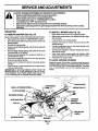
TO LEVEL
MOWER
HOUSING
Adjust the mower while tractor is parked on level ground or
driveway. Make sure tires are properly inflated(See "PRODUCT SPECIFICATIONS" section ofthis manual). Iftires are
over or underinflated, you will not properly adjust your
mower.
SQUARE HOLE
SUSPENSION
ARMS
ENGINE PULLEY
FRONT UNK
RETAINER SPRING
RETAINER
SPRINGS
ANTI-SWAY BAR
COLLAR,
(BOTH SIDES)
SHIELD
HOUSING GUIDE
LARGE RETAINER
SPRING
BRACI_EI"
FIG. 19
19
SERVICE AND ADJUSTMENTS
SIDE-TO-SIDE ADJUSTMENT (See Figs. 20 and 21)
•
Raise mower to its highest posrtion.
•
At the midpoint of both sides of mower, measure height
from bottom edge of mower to ground. Distance =A"on
both sides of mower should be the same or within 1/4"
of each other.
•
•
•
'_.D___
MANDREL
FIG. 22
If adjustment is necessary, make adjustment on one
side of mower only.
To raise one side of mower, tighten lift link adjustment
nut on that side.
BOTH FRONT LINKS MUST BE EQUAL IN LENGTH
To lower one side of mower, loosen lift link adjustment
nut on that side.
NOTE: Each full turn of adjustment nut will change mower
height about 1/8".
•
Recheck measurements afteradjusting.
BOTTOM
EDGE
OF MOWER
_
[
BoTroM
EDGE
A----_OF
MOWER
_
oo.oo
"A'-qWIJ ROU..
;.;2
TRUNNION
2222
RG. 20
FRONT
UNKS
FIG. 23
TO
._oSUSPENSION
/
1 /
_
ARM
--
! \\
_l_m._._O_--_-/--_
REPLACE
MOWER
BLADE
DRIVE
BELT
(See Fig. 24)
_
The mower blade drive belt may be replaced without tools.
Park the tractor on level surface. Engage parking brake.
BELT REMOVAL -
UFT LINK
/ADJUSTMENT
•
Remove mower from tractor (See "TO REMOVE
MOWER" in this section of this manual).
•
Work belt off both mandrel pulleys and idler pulleys.
•
Pull belt away from mower.
BELT INSTALLATION •
Install new belt in reverse order of removal.
FIG. 21
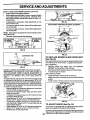
FRONT-TO-BACK ADJUSTMENT (See Figs. 22 and 23)
IMPORTANT: DECK MUST BE LEVEL SIDE-TO-SIDE. IF
THE FOLLOWING FRONT-TO-BACK ADJUSTMENT IS
NECESSARY, BE SU RE TO ADJUST BOTH FRONT LINKS
EQUALLY SO MOWER WILL STAY LEVEL SIDE-TOSIDE.
To obtain the bestcutting results, the mower housing should
be adjusted so that the front is approximately 1/8" to 112"
lower than the rearwhen the mower isin its highest position.
Checkadjustment on dght side oftractor. Measure distance
"D" directly in front and behind the mandrel at bottom edge
of mower housing as shown.
•
Before making any necessary adjustments, check that
both front links are equal in length.
•
If links are not equal in length, adjust one link to same
length as other link.
•
To lower front ofmower loosen nut"E"on bothfront links
an equal number of turns.
•
Whendistance"D"isll8"toll2"loweratfrontthanrear,
tighten nuts "P against trunnion on both front links.
•
To raise front of mower, loosen nut "P from trunnion on
both front links. Tighten nut "E" on both front links an
equal number of turns.
•
When distance"D"is 1/8" to 1/2" Iowerat front than rear,
tighten nut "P against trunnion on both front links.
•
Recheck side-to-side adjustment.
•
•
Make sure belt is in all pulley grooves and inside all belt
guides.
Install mower in reverse order of removal instructions.
IDLER PULLEYS_
FIG. 24
TO ADJUST
BRAKE
(See
Fig. 25)
Your tractor is equipped with an adjustable brake system
which is mounted on the side of the transaxle.
20
If tractor requires more than six (6) feet stopping distance at
high speed in highest gear on a level dry concrete or paved
surface, then brake must be adjusted.
SERVICE AND ADJUSTMENTS
TRANSAXLE
Depressclutch/brake pedal and engage parking brake.
Measure distance between brake operating arm and nut
=A"on brake rod.
While holding motion control lever in place, loosen the
adjustment bolt.
•
Move motion control lever to the neutral (N) (lock gate)
position.
•
Tighten adjustment bolt securely.
NOTE: Ifadditionalclearanco is needed to get to adjustment
bolt, move mower deck height to the lowest position.
After above adjustment is made, if the tractor still creeps
forward or backward while motion control lever is in neutral
position, follow these steps:
•
Loosen the adjustment bolt.
•
Move the motion control lever 1/4 to 112 inch in the
direction it is trying to creep.
•
Tighten adjustment bolt securely.
•
Start engine and test.
•
If tractor still creeps, repeat above steps until satisfied.
NUT "A"
DO NOT TOUCH THIS NUT. IF FURTHER BRAKE ADJUSTMENT IS NECESSARY CONTACT YOUR NEAREST
AUTHORIZED
SERVICE CENTER/DEPARTMENT
FIG. 25
MOTION
DRIVE
LEVER
•
WITH PARKING BRAKE "ENGAGED"
REPLACE
CONTROL
NEUTRAL
ADJUSTMENT
(See Fig. 27)
The motion control lever has been preset at the factory and
adjustment should not be necessary.
•
Loosen adjustment bolt in front of the right roar wheel,
and lightly tighten.
•
Start engine and move motion control lever untiltractor
does not move forward or backward.
•
Hold motion centrol lever inthat positionand turn engine
off.
If distance is otherthan 1-9116",loosen jam nut and turn
nut =A" until distance becomes 1-9/16". Retighten jam
nut against nut =A".
Road test tractor for proper stopping distance as stated
above. Readjust if necessary. If stopping distance is
still greater than six (6) feet in highest gear, further
maintenance is necessary. Contact your nearest authorized service center/department.
ro
MOTION
MOTION
NEUTRAL
fLOCK GATE
CONTROL
BELT
ISee Fig. 26)
Parkthetractoron level surface. Engage parking brake. For
assistance, there is a belt installation guide decal on bottom
side of left footrest.
Remove mower (See "TO REMOVE MOWER" in this
section of this manual.)
Remove belt from stationary idler and clutching idler.
Pull belt slacktoward rear of tractor. Carefully remove
belt upwards from transmission input pulley and over
cooling fan blades.
Pull belt toward front of tractor and remove downward
from around engine pulley.
Install new belt by reversing above procedure.
ADJUSTMENT
BOLT
FIG. 27
TRANSMISSION
Should your transmission require removal for service or
replacement, it should be purged after reinstallation and
before operating the tractor. See "PURGE TRANSMISSION" in the Operation section of this manual.
TO ADJUST
ENGINE
PULLEY
CLUTCNING
FRONT
WHEEL ALIGNMENT
WHEEL
TOE-IN/CAMBER
The front wheel tce-in and camber are not adjustable on you r
tractor. If damage has occurred to affect the front wheel toein or camber, contact your nearest authorized service
center/department.
TRANSMISSION
PULLEY __
FIG. 26
STEERING
If steering wheel crossbars are not horizontal (left to right)
when wheels are positioned straight forward, remove steering wheel and reassemble per instructions in the Assembly
section of this manual.
._
,DLER /,
INPUT
REMOVAL/REPLACEMENT
21
SERVICE AND ADJUSTMENTS
FRONT
WHEEL
CAMBER
PosrnvE TERMINAL
The front wheel camber is not adjustable on your tractor. If
damage has occurred to affect the front wheel camber,
contact your neerest authorized service center/department.
TO REMOVE
WHEEL
FOR
REPAIRS
(See Fig. 28)
•
Block up axle securely.
•
Remove axle cover, retaining ring and washerstoallow
wheel removal (rearwheel contains a square key - Do not
lose).
•
Repairtireand reassemble.
•
Onrearwheelsonly: aligngroovesinrearwheelhuband
axle. Insert square key.
•
Replace washers and snap retaining ringsecurely inaxle
groove.
•
Replace axle cover.
NOTE: To seal tire punctures and prevent flat tires due to
slow leaks, tire sealant may be purchased from your local
parts dealer. Tire sealant also prevents tire dry rot and
corrosion.
RETAINING
r_
CHASSIS
BATTERY
POSITIVE
TERMINAL
TO REPLACE HEADLIGHT BULB
•
•
•
•
Raise hood.
Pullbulb holder out ofthe hole inthe backside ofthe gdlL
Replace bulb in holder and push bulb holder securely
back into the hole in the backside of the grill.
Close hood.
"_.111
1
cov.WASRERS
j
SQUARE KEY
(REAR WHEEL
TERMINAL
RG. 29
__.'_,
.,.G\\ I\
I ._11_--_
AXLE
NEGATIVETERMINAL
ONLY)
FIG. 28
INTERLOCKS
RELAYS
Loose or damaged wiring may cause your tractor to run
poorly, stop running, or prevent it from starting.
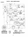
Check wiring. See electricalwiringdiagram inthe Repair
Parts section.
TO
TO START ENGINE WITH A WEAK BATrERY
(See Fig. 29)
AND
REPLACE
FUSE
Replace with 20 amp automotive-type plug-infuse. The fuse
holder is located behind the dash.
CAUTION: Lead-acid batteries generate
explosive gases. Keep sparks, flame
and smoking materials away from batteries. Always wear eye protection when
around batteries.
TO REMOVE
(See Fig. 30)
•
•
If your battery is too weak to start the engine, it should be
recharged. If "jumper cables" are used for emergency
starting, follow this procedure:
IMPORTANT: YOUR TRACTOR IS EQUIPPED WITH A 12
VOLT NEGATIVE GROUNDED SYSTEM. THE OTHER
VEHICLE MUST ALSO BE A 12 VOLT NEGATIVE
GROUNDED SYSTEM. DO NOT USE YOUR TRACTOR
BATTERY TO START OTHER VEHICLES.
TO ATI'ACH JUMPER CABLES -
•
HOOD AND GRILL
Raise hood.
Unsnap headlight wire connector.
Stand in front oftractor. G rasp hood at sides, tilt toward
engine and lift off of tractor.
To replace, reverse above procedure.
HEADLIGHT
, WIRE
CONNECTOR
•
Connect each end of the REDcabletothe POSITIVE (+)
terminal of each battery, taking care not to short against
chassis.
Connect one end of the BLACK cable to the NEGATIVE
(-) terminal of fully charged battery.
Connect the other end of the BLACK cable to _od
CHASSIS GROUND, away from fuel tank and battery.
TO REMOVE CABLES, REVERSE ORDER •
•
BLACK cable first from chassis and then from the fully
charged battery.
RED cable last from both batteries.
ASSEMBLY
FIG. 30
22
SERVICE AND ADJUSTMENTS
ENGINE
ACCELERATION TEST •
Move throttle control lever from slow to fast position. If
engine hesitates or dies, turn idlefuel adjusting needle
out (counterclockwise) 1/8 tum. Repeat test and continue to adjust, if necessary, until engine accelerates
smoothly.
High speed stop isfactory adjusted. Do not adjust - damage
may result.
IMPORTANT:
NEVER TAMPER WITH THE ENGINE
GOVERNOR, WHICH IS FACTORY SET FOR PROPER
ENGINE SPEED. OVERSPEEDING THE ENGINE ABOVE
THE FACTORY HIGH SPEED SETTING CAN BE
DANGEROUS. IF YOU THINK THE ENGINE-GOVERNED
HIGH SPEED NEEDS ADJUSTING, CONTACT YOUR
NEAREST
AUTHORIZED
SERVICE
CENTER/
DEPARTMENT, WHICH HAS PROPER EQUIPMENT AND
EXPERIENCE
TO
MAKE
ANY
NECESSARY
ADJUSTMENTS.
Maintenance, repair, or replacement ofthe emission control
devices and systems, which are being done at the custom_=rsexpense, may be performed by any non-read engine
-epair establishment or indMdual. Warranty repairs must be
oerforrned by an authorized engine manufacturer's service
3utlet.
i"O ADJUST
THRO'n'LE
CONTROL
CABLE
(See Fig. 31)
]he throttle control has been preset at the factory and
adjustment should not be necessary. Chock adjustment as
descdbed below before loosening cable. If adjustment is
,_ecessary, proceed as follows:
With engine not running, movethrettle control lever from
slow to choke position. Slowly move leverfrem choke to
fast position.
Check to see if hole in throttle lever and hole in speed
control bracket are aligned.
If holes are not aligned, loosen cable clamp screw and
align the holes by inserting a pencil or a 1/4" drill bit
through both holes.
Pull throttle cable up to remove slack and tighten cable
clamp screw. Remove alignment pencil or ddll bit.
TO ADJUST
CARBURETOR
CABLE
CLAMP_
SCREW
SPEED
BRACKET
(See Fig. 32)
]he carburetor has been preset at the factory and adjustment should not be necessary. However, minor adjustment
-nay be required to compensate for differences in fuel,
temperature, altitude or load. If the carburetor does need
_djustment, proceed as follows:
In general, turning the adjusting needles in (clockwise)
decreases the supply of fuel to the engine giving a leaner
fuel/air mixture. Tuming the adjusting needles out (counterclockwise) increases the supply of fuel to the engine giving
a dcher fuel/air mixture.
IMPORTANT:
DAMAGE TO THE NEEDLES AND THE
SEATS IN CARBURETOR MAY RESULT IF NEEDLE IS
TURNED IN TOO TIGHT.
NOTE: The carburetor on this engine is low emission. It is
9quipped with an idle fuel adjusting needle with a limiter cap,
which allows some adjustment within the limits allowed by
the cap. Do not attempt to remove the limiter cap. The limiter
cap cannot be removed without breaking the adjusting
needle.
•
Be sure you have aclean air fiifer and the threttle contrel
cable is adjusted properly (see above).
Start engine and allow to warm for five minutes. Make
adjustments with engine running and shift/motion control
lever in neutral (N) position.
Idle sDeed settino - With throttle control lever in slow
position, engine should idle at 1750 RPM. If engine idles
too slow orfast, turn idle speed adjusting screw in orout
until correct idle is attained.
•
Idle fuel needle settine- With threttle controllever in slow
position, turn idle fuel adjustment needle in (clockwise)
until engine begins to die and then turn out (counterclockwise) until engine runs rough. Tum needle to a point
midway between those two positions.
Recheck idle speed. Readjust if necessary.
THRO'I'rLE LEVER
FIG. 31
IDLE SPEED
ADJUSTING
SCREW
IDLE FUEL
ADJUSTING
NEEDLE
FIG. 32
23
STORAGE
ENGINE
Immediately prepare your tractorfor storage atthe end ofthe
season or if the tractor will not be used for 30 days or more.
FUEL SYSTEM
I_11_
gasoline in the tank inside a building
where fumes may reach an open flame
or spark. Allow the engine to cool
AUTION: Neverstorethetreotorwith
before storing in any enclosure.
IMPORTANT:
IT IS IMPORTANT TO PREVENT GUM
DEPOSITS FROM FORMING IN ESSENTIAL FUEL SYSTEM
PARTS SUCH AS CARBURETOR, FUEL FILTER, FUEL
HOSE, OR TANK DURING
STORAGE.
ALSO,
EXPERIENCE INDICATES THAT ALCOHOL BLENDED
FUELS (CALLED GASOHOL OR USING ETHANOL OR
METHANOL) CAN ATTRACT MOISTURE WHICH LEADS
TO SEPARATION AND FORMATION OF ACIDS DURING
STORAGE.
ACIDIC GAS CAN DAMAGE THE FUEL
SYSTEM OF AN ENGINE WHILE IN STORAGE.
•
Drain the fuel tank.
I
TRACTOR
Remove mower from tractorfor winter storage. When mower
is to be stored for a pedod of time, clean it thoroughly,
remove all dirt, grease, leaves, etc. Store in a clean, dry
area.
•
Clean entire tractor (See =CLEANING" in the Customer
Responsibilities section of this manual).
•
Inspect and replace belts, if necessary (See belt replacement instructions in the Service and Adjustments
section of this manual).
•
Lubricate as shown in the Customer Responsibilities
section of this manual.
•
•
•
•
•
NOTE:
Fuel stabilizer is an acceptable alternative in
minimizing the formation of fuel gum deposits during storage. Add stabilizer to gasoline in fuel tank or storage
container. Always follow the mix ratio found on stabilizer
container. Run engine at least 10 minutes after adding
stabilizer to allow the stabilizer to reach the sarburetor. Do
not drain the gas tank and carburetor ifusing fuel stabilizer.
Be sure that all nuts, bolts and screws are securely
fastened. Inspect moving parts for damage, breakage
and wear. Replace if necessary.
Touch up all rusted or chipped paint surfaces; sand
lightlybefore painting.
ENGINE
•
•
•
OIL
Drain oil(with engine warm) and replace withclean engine oil.
(See "ENGIN E" in the Customer Responsibilities section of
this manual).
BATTERY
•
•
Start the engine and let it run until the fuel lines and
carburetorare empty.
Never use engine or carburetor cleaner products in the
fuel tank or permanent damage may occur.
Use fresh fuel next season.
Fully charge the battery for storage.
After a period of time in storage, battery may require
recharging.
To belp preventcorrosionand power leakage dudng long
periods of storage, battery cables should be diSconnected and battery cleaned thoroughly (see TO CLEAN
BATrERY ANDTERMINALS" inthe Customer Respensibilities section of this manual).
After cleaning, leave cables disconnected and place
cables where they cannot come in contact with battery
terminals.
CYLINDER(S)
•
•
•
•
Remove spark plug(s).
Pour one ounce of oil through spark plug hole(s) into
cylinder(s).
Tum ignition key to =STAR'I" positionfor a few seconds
to distribute oil.
Replace with new spark plug(s).
OTHER
If battery is removed from tractor for storage, do not
store battery directly on concrete or damp surfaces.
•
•
Do not store gasoline from one season to another.
Replace your gasoline can if your can starts to rust.
Rust and/or dirt in your gasoline will cause problems.
•
If possible, store your tractor indoors and cover itto give
protection from dust and dirt.
•
Cover your tractor with a suitable protective cover that
does not retain moisture. Do not use plastic. Plastic
cannot breathe which allows condensation to form and
will cause your tractor to rust.
IMPORTANT: NEVER COVER TRACTOR WHILE ENGINE
AND EXHAUST AREAS ARE STILL WARM.
24
TROUBLESHOOTING
PROBLEM
CAUSE
Will not start
1.
2.
3.
4.
5.
6.
7.
Out of fual.
Engine not 'CHOKED"
Engine flooded.
Bad spark plug.
Dirty air filter.
Dirty fuel filter.
Water in fuel.
8.
9.
Loose or damaged wiring.
Carburetor out of adjustment
10.
Hard to start
Engine will not turn over
Engine
;tart
clicks but will not
toss of power
properly.
1.
I=illfuel tank.
2.
3.
4.
5.
6.
7.
Sea -TO START ENGINE" in Operation sso_on.
Wait several minutes before attempting to start.
Replace spark plug.
Clean/replace air filter.
Replace fuel filter.
Drain fuel tank and carburetor, refill tank with fresh
gasoline and replace fuel filter.
Check all wiring,
See "To Adjust Carburetor- in Service Adjustments
section.
8.
9.
Engine valves out of adjustment.
10.
Contact an authorized service can_rldepartment.
Dirty air filter.
Bad spark plug.
Weak or dead battery.
Dirty fuel filter.
Stale or dirty fuel.
Loose or damaged widng.
Carburetor out of adjustment.
1.
2.
3.
4.
5.
6.
7.
Clean/replace air filter.
Replace spark plug.
Recharge or replace battery.
Replace fuel filter,
Drain fuel tank and refill with fresh gasoline.
Check all wiring.
See "To Adjust Carburetor- in Service Adjus_ents
section.
8.
Enginevalvesout of edj_tmenL
8,
Contact an authorized service center/department.
1.
2.
3.
4.
Brake pedal not depressed.
Attachment clutch is engaged.
Weak or dead battery.
Blown fuse.
5.
6.
7.
8.
9.
Corroded battery terminals.
Loose or damaged widng.
Faulty ignilJnoswitch.
Faulty solenoid or starter.
Faulty operator presence switch(es).
1.
2.
3.
4.
5.
6.
7.
8.
Depress clutofv13rake pedal.
Disengage attachment clutch.
Recharge or replace battery.
Replace fuse.
Clean battery terminals.
Check all widng.
Cheddreplace ignition switch.
ChackJreptace solenoid or starter.
9.
Contact an authorized servica cantar/departmant.
t.
2.
3.
4.
Weak or dead battery.
Corroded battery terminals.
Loose or damaged wiring.
Faulty solenoid or starter.
1.
2.
3.
4.
Recharge or replace battery.
Clean battery terminals.
Check all wiring.
Chack/replace solenoid or starter.
1.
2.
3.
4.
5.
6.
7.
8.
9.
Cuffing too much grass/too fast.
Throttle in =CHOKE" position.
Build-up of grass, leaves and trash under mower.
Dirty air filter.
Low oil level/dirty oil.
Faulty spark plug.
Dirty fuel filter.
Stale or dirty fuel.
Water in fuel.
1.
2.
3.
4.
5.
6.
7.
8.
9.
Set in =Higher Cut" position/reduce speed.
Adjust throttle control.
Clean underside of mower housing.
Clean/replace air filter.
Check oil level/change oil.
Clean and regap or change spark plug.
Replace fuel filter.
Drain fuel tank and refill with fresh gasoline.
Drain fuel tank and carburetor, refill tank with fresh
gasoline and replace fuel filter.
Connect and tighten spark plug wire.
Clean engine air screen/fins.
Clean/replace muffler.
Check all widng.
See "To Adjust Carburetor" in Service Adjustments
section.
15.
vibration
CORRECTION
1.
2.
3.
4.
5.
6.
7.
10.
11.
12.
13.
14.
Excessive
POINTS
Spark plug wire loose.
Dirty engine air screen/fins.
Dirty/clogged muffler.
Loose or damaged wiring.
Carburetor out of adjustment.
10.
11.
12.
13.
14.
Engine valves out of adjustment.
15.
Contact an authorized service canter/department.
1.
2.
3.
Replace blade. Tighten blade bolt.
Replace blade mandrel.
Tighten loose part(s). Replace damaged parts.
1.
2.
Wom, bent or loose blade.
Bent blade mandrel.
3.
Loose/damaged
part(s).
25
TROUBLESHOOTING
PROBLEM
Engine conUnues to run
when operator leaves
seat with attachment
POINTS
CORRECTION
CAUSE
1.
Faulty opemfor-safotypresence control system.
1.
Check widng, switches and conneclJons. If not
corrected, contact an authorized service center/
departmanL
1.
2.
3.
4.
Worn, bent or loose blade.
Mower deck not level.
Buildup of grass, leaves, and trash under mower.
Bent blade mandrel.
1.
2.
Replace blade. Tightan blade bolt.
Level mower deck.
5.
Clogged mower desk vent holes from buildup of
grass, leaves, and ttash around mandrels.
3.
4.
5,
Clean underside of mower housing.
Replace blade mandrel.
Clean around mandrels to open vent holes.
1.
2.
3.
4.
Remove obstruction.
Replace mowerddve bell
Replaceidler pulley.
Replace blade mandrel.
clutch engaged
Poor cut - uneven
Mower
rotate
blades will not
Poor grass discharge
Headlight(s) not working
(if so equipped)
Battery will not charge
Loss of drive
Engine "backfires"
when turning engine
"OFF"
1.
Obstruction
2,
3.
4.
Worrddamaged mower ddve belt.
Frozen idler pulley.
Frozen blade mandrel.
in clutch mechanism.
1.
2.
3.
4.
Engine speed too slow.
Travel speed too fast.
Wet grass.
Mower deck not level.
5.
6.
7,
8.
Low/uneven _re air pressure.
Worn, bent or loose blade.
Buildup of grass, leaves and trash under mower.
Mower ddve belt worn.
9.
10.
11.
Blades improperly installed.
Improper blades used.
Clogged mower deck vent holes from buildup of
grass, leaves, and trash around mandrels.
1.
2.
3.
4.
5.
6.
7.
8.
9.
10.
11.
Place throttle control in =FAST" position.
Shift to slower speed.
Allow grass to dry before mowing.
Level mower deck.
Check tires for proper air pressure.
Replace/sharpen blade. Tighten blade bolt.
Clean underside of mower housing.
Replace mower drive bell
Reinstall blades sharp edge down.
Replace with blades listed in this manual.
Clean around mandrels to open vent holes.
1.
Switch is "OFF'.
1.
Turn switch "ON'.
2.
3.
4.
5,
Bulb(s) or lamp(s) bumed out.
Faulty light switch.
Loose or damaged widng.
Blown fuse.
2.
3.
4.
5.
Replace bulb(s) or lamp(s).
Check/replace light switch.
Check widng and connections.
Replace fuse.
1.
2.
Bad battery cell(s).
Poor cable connec_ons.
1.
2.
Replace battery.
Check/claan all connections.
3.
4.
Faulty regulator (if so equipped).
Faulty alternator.
3.
4.
Replace regulator.
Replace alteroak_r.
1.
2.
3.
Freewheel control in "disengaged" position.
Motion ddve belt wom, damaged, or broken.
Air trapped in transmission during shipment
or servicing.
1.
2.
3.
Place freewheel control in =engaged" position.
Replace motion ddve belt.
Purge transmission.
1.
Engine throttle contro_ not set at "SLOW"
position for 30 seconds before stopping engine.
1.
Move throt_e control to "SLOW* position and allow
to idle for 30 seconds before stopping engine.
26
TRACTOR - - MODEL NUMBER 944.602951
SCHEMATIC
l
BATTERY
SOLENOID
I
RED
RE.
FUSE
AMMETER
(OPTIONAL)
I
STARTER
,
WHITE
BLACK
•
wHrrE
CLUTCH / BRAKE
I
r (PEDAL UP)
i BLUE
I
,' _EL,
ATCMENT
IGNITION
SWITCH
I
C_
(CLUTCH OFF)
i
I GREEN
L
•F
18s
I
I
' _
)87A
'
'
......
I
PRESENCE
I--I 8_
.I
FUEL SHUT-OFF
SOLENOID
(IF SO EQUIPPED)
I
_-A_R
BLUE
I
861
BLUE
1
SEAT SWITCH
(NOT OCCUPIED)
°NEi
RELAY #1
86
BLACK
SPARK
UNIT
t
GAP
(2 PLUGS ON
TWIN CYL,
ENGINES)
PLUG
IGNITION
YELLOW
/
z
CHARGING SYSTEM OUTPUT
15 AMP
DC O 3600
j_
RPM
•
REGULATOR
[
--
/
!
_
_\
I ALTERNATOR
i
(REGULATOR
DISCONNECTED)
28 VOLTS
O 3600
AC
BROWN
{
•
_
PRESENCE RELAY #3
OPERATOR
_
I
1
i85
86,
RPM
BLACKi
•
BLUE
I
RED
IGNITION
SWITCH
POSITION
CIRCUIT
=MAKE"
OFF
RUN/UGH]
M+G+A1
B+A1
NONE
A2+L
RUN
B+A1
NONE
START
3 + S + A1
NONE
i
Ii_
BLACK
HEADLIGHTS
--0--
I0_7 al
r°B:J
RELAY
NON-REMOVABLE
CONNECTIONS
©
REMOVABLE
CONNECTIONS
WIRING INSULATED CLIPS
NOTE: IF WIRING INSULATED CLIPS WERE REMOVED FOR
SERVICING OF UNIT, THEY SHOULD BE REPLACED TO
PROPERLY SECURE YOUR WIRING.
27
REPAIR PARTS
TRACTOR
- - MODEL NUMBER
944.602951
ELECTRICAL
22
i
J
42
41
24_
26
27
I
I
I
I
I
25
\
.%
)
/
/
/
/
!
i
//
/
/
29
I
I
28
27
\
\
I
I
I
I
28
REPAIR PARTS
TRACTOR - - MODEL NUMBER 944.602951
ELECTRICAL
KEY
NO.
PART
NO.
DESCRIPTION
1
2
8
16
21
22
24
25
26
27
28
29
30
33
40
41
42
43
45
52
81
89
163465
74760412
176689
176137
175688
4152J
4799J
146147
175158
73510400
4207J
160784
175566
14O4O3
179722
71110408
131563
178861
122822X
141940
109748X
18O449
Battery 12 Volt 28 Amp
Bolt Hex Hd 1/4-20unc X 3/4
Battery Box
Switch Interlock Push-In
Harness Asm Light W/4152J
Bulb Light #1156
Cable Battery 6 Ga 11 "red
Cable Battery 6 Ga w/16 wire,red
Fuse 20 AMP
Nut Kep Hex 1/4-20
Cable Ground 6 Ga 12" black
Switch Plunger
Switch Ign
Key Ign
Harness Ign
Bolt BIk Fin Hex 1/4-20unc X 1/2
CoverTerminal Red
Solenoid
Ammeter
Protection Wire Loop (Hourmeter)
Relay Asm
CoverTerminal
NOTE:
All component dimensions give in U.S. inches
1 inch = 25.4 mm.
29
REPAIR PARTS
TRACTOR - - MODEL NUMBER 944.602951
CHASSIS AND ENCLOSURES
28
39
_
..----- 159
166
31
2O8
6O
•3
37
2O8
74
3O
REPAIR PARTS
TRACTOR
CHASSIS
AND
- - MODEL NUMBER
944.602951
ENCLOSURES
KEY
NO.
1
2
3
5
9
10
11
13
14
17
18
25
26
28
29
30
31
37
38
39
58
60
64
74
142
143
144
145
159
166
206
207
208
212
--
PART
NO.
174619
176554
17060612
155272
168337X011
STD533710
174996
172105X010
17490608
174330X612
126938X
19131312
STD541437
177403
174332X599
175692X612
139976
17490508
175710
174714
150127
STD533707
154798
STD541437
175702
154966
175582
156524
155123X428
164863
170165
17670508
17670608
175143
5479J
DESCRIPTION
Chassis
Drawbar
Screw 3/8-16x3/4
Bumper Hood/Dash
Dash SIkscr Stl
Bolt Carriage 3/8-16 x 1
Panel Dash Lh
Panel Dash Rh
Screw Thdrol 3/8-16 x 1/2
Hood
BumperHood
Washer 13132 X 13/16 X 12 Ga
Nut Lock HexW/Ins 3/8-16 Unc
Grille/Lens Asm
LensGrille
Fender Footrest STLT Pnt
Bracket Support Fender
Screw Thdrol 6/16-18 x 1/2 rY-r
Bracket, Asm. Pivot, Mower Rear
Bracket Pivot Laser Lt
Duct Air Engine
Bolt Rdhd Sqnk 3/8-16unc x 3/4
Dash Lower STLT
Nut Crownlock 3/8-16 UNC
Plate Reinforcement STLT
Bracket Swaybar Chassis
Bracket Pnt Footrest STLT
Rod Pivot Chassis/Hood
Cupholder STLT Black
Screw Hwhd Hi-Lo #13-16 x 3/4
Bolt Shoulder 5/16-18 UNC
Screw Thdrol 5/16-18 x 1/2
Screw Thdrol 3/8-16 x 1/2
Insert Lens Reflective
Plug Button
NOTE: All component dimensions given in U.S. inches
1 inch = 25.4 mm
31
REPAIRPARTS
O_iv_
TRACTOR
"" MODELNUMsERS'M.SO2es_
REPAIR
PARTS
TRACTOR
- - MODEL NUMBER
944.602951
DRIVE
KEY PART
NO. NO.
1
8
10
14
15
16
19
21
22
24
25
26
27
28
29
30
32
34
35
36
37
38
39
41
47
48
49
50
51
52
53
55
56
57
59
61
62
63
64
65
66
165866
STD561210
10040400
74490544
S'rD541431
STD541437
174779
169498
STD541273
106888X
STD551037
STD561210
175765
71673
169592
STD523107
175578
120183X
STD551062
STD571810
179114
74760648
175556
127783
154407
123205X
STD523715
STD541437
STD541431
105710X
105709X
17060620
140294
169691
17120614
8883R
175410
71170764
STD551143
154778
KEY PART
NO. NO.
DESCRIPTION
Transaxle (See Breakdown)
Hydro Gear Model 314-0510
Rod Shift
Pin Cotter 1/8 x I CAD
Washer Lock Hvy. Helical 114
Bolt, Hex FLGHD 5/16-18 Gr. 5
NutLockHexW/Ins
5/16-18Unc
Nut Lock Hex W/Wsh 3/8-16 Uric
Knob, Deluxe 1/2-13
Rod, Brake
Nut
Spdng, Brake Rod
Washer
Pin Cotter 1/8 x 3/4 CAD.
ROd, Parldng Brake
Cap, Parking Brake
Bracket, Transaxle
BoltHexHd 5/16-18Uncx3/4
Shaft, Foot Pedal
Bearing, Nylon
Washer
Pin, Roll
Pulley, Composite,Flat
Bolt Fin Hex 3/8-16unc x 3
Keeper, Belt Retainer
Pulley, Idler, V-Groove
Bellcrank Clutch Grnd Dry STL
Retainer, Belt
Bolt
NutCrownlock 3/8-16UNC
NutCrownlock 5/16-18UNC
Link, Clutch
Spring, Return, Clutch
Screw 3/8-16 x 1-1/4
V-Belt, Ground Drive
Keeper, Center Span
Screw 3/8-16 x .875
Cover, Pedal
Engine Pulley
Bolt Hex 7/16-20 x 4 Gr. 5
Washer
Keeper Belt Engine
70
71
73
74
75
76
77
78
81
82
83
84
89
90
95
96
116
120
150
151
156
158
159
161
162
163
164
165
166
168
169
197
198
199
200
2(_
212
250
134683
169183
169182
137057
121749X
STD581075
123583X
121748X
165596
165711
19171216
169594
164890X42.8
124346X
170201
STD624003
72140608
73900600
175456
19133210
166002
165,589
165494
72140406
73680400
74780416
19091010
165623
166880
165492
165580
169613
169593
169612
72140508
72110614
145212
17060612
DESCRIPTION
Guide Belt Mower RH
StrapTorque Lh
StrapTorque Rh
Spacer, Axle
Washer 25132 x 1-114 x 16 Gauge
E-Ring
Key, Square
Washer 25132 x 1-5/8 x 16 Gauge
Shaft Asm. Cross
SpringTorsion
Washer 17/32 x 3/4 x 16 Ga.
Link, Transaxle
Console, Shift
Nut Self Thd Wsh-Hd 1/4 Zinc
Control Asm Bypass Hydro
Retainer Spdng 1 "Zinc/Cad
Bolt RDHD SQNK 3/8-16unc x 1
Nut Lock Fig 3/8-16unc
Spacer Retainer
Washer 1 3/32 x 2 x 10 Ga.
Washer Srrted 5/16 ID x I x .125
Bracket Shift Mount
Hub Tapered Flange Shift LT
Bolt Rdhd Sqnk 1/4-20 x 3/4 Gr. 5
Nut Crownlock 1/4-20 Uric
Bolt Hex Fin 1/4-20 Uncx I Gr. 5
Washer 5/8x .281 x 10 Ga.
Bracket Pivot Lever
Screw 5/16-18 x 518
Bolt Shoulder 5/16-18 x .561
Plate Fastening LT
Nyliner Snap-In 5/8" ID
Washer Nyl 7/8 ID x .105"
Bolt Shoulder5/16-18 UNC
Bolt Rdhd Sqnk 5/16-18 UNC x 1
Bolt Carr Sh 3/8-16 x 1-3/4 Gr. 5
Nut Hexflange Lock
Screw 3/8-16 x .75
NOTE: All component dimensions given in U.S. inches
1 inch = 25.4 mm
33
REPAIR PARTS
TRACTOR
STEERING
- - MODEL NUMBER
ASSEMBLY
C;
t
•
L
_'-_-L
42
I
88
J
I
29
J
46
\
\
\
2_
\
\
J
\
34
944.602951
REPAIR PARTS
TRACTOR
STEERING
- - MODEL NUMBER 944.602951
ASSEMBLY
KEY
NO.
PART
NO.
1
2
3
4
5
6
7
8
9
10
11
13
15
17
26
28
29
30
32
36
37
38
39
40
41
42
43
44
46
47
51
54
63
65
67
68
71
82
85
88
91
159944X428 Wheel Steering
175131
Axle Asm
16984O
Spindle Asm LH
169839
Spindle Asm RH
62661-1
Beadng Race Thrust Harden
Washer 25/32 X 1-5/8 X 16 Ga
121748X
Washer 27/32 x 1-1/4 x 16 Ga
19272016
12OO0029
Ring Klip #t5304-75
3366R
Bearing
175121
Link Drag Extended Stamp
STD551137
Washer Lock Hvy Hlcl Spr 3/8
136518
Spacer Bearing Axle
145212
Nut Hex Flange Lock
177876
Shaft Asm Strg
126847X
Bushing
Washer 13/32 x 7/8 x 16 Ga
19131416
17060612
Screw 3/8-16 x 3/4
76020412
Pin Cotter 1/8 x 3/4
Rod Tie
130465
155099
Bushing Strg
152927
Screw
159946X428 Insert Cap Strg Wh
19132411
Washer 13/32 X 1-1/20 x 11
Lock nut
STD541537
159945
Adaptor Wheel Strg
145054X428 Boot Steering Shaft
121749X
Washer 25/32 X 1 1/4 X 16 Ga
153720
Extension Steering Shaft LR/LT
121232X
Cap Spindle FrTop BIk
6855M
FittingGrease
Nut Lock Hex w/Ins 5/15-18
SrD541431
Bolt Fin Hex 5/16-18 Unc x 1-1/4
STD523112
STD523710
Bolt Fin Hex 3/8-15unc x 1 Gr. 5
160367
Spacer Brace Axle
72140618
Bolt Rdhd Sq 3/8-16 x 2-1/4
16,9827
Axle, Brace
175146
Steering Asm
Bracket
169835
133835
Fastener Christmas Tree
Bolt Shoulder 7/16-20 Unc
175118
175553
Clip Steering
DESCRIPTION
NOTE: All component dimensions given in U.S. inches
1 inch = 25.4 mm
35
REPAIR PARTS
TRACTOR
SEAT
- - MODEL NUMBER 944.602951
ASSEMBLY
12
KEY
NO.
1
2
3
4
5
6
7
6
9
10
11
12
PART
NO.
18O597
180166
71110616
19131610
145O06
STD541437
124181X
17000616
19131614
180186
166369
121246X
DESCRIPTION
Seat
Bracket Pivot Fender
Bolt Fin Hex 3/8-16unc X 1
Washer 13/32 X 1 X 10 Ga
Clip Push-In
Nut Hex w/Ins. 3/8-16 Unc
Spring Seat Cprsn 2 250 BIk Zi
Screw 3/8-16 X 1.5
Washer 13/32 X 1 X 14 Ga.
Pan Seat
Knob Seat
Bracket Mounting Switch
KEY
NO.
PART
NO.
DESCRIPTION
13
14
15
16
17
18
21
22
24
25
121248X
72050412
1343OO
121250X
123976X
124238X
171852
STD541431
19171912
127018X
Bushing Snap BIk Ny150 Id
Bolt Rdhd Sqnk 1/4-20xl -1/2
Spacer Split 28x 96 Yel Zinc
Spring Cprsn 1 27 BIk Pnt
Nut Lock 1/4 Lge Fig Gr 5 Zinc
Cap Spring Seat
Bolt Shoulder 5/16-16 Unc
Nut Hex LockW/Ins 5/16-18
Washer 17/32 X 1-3/16 X 12 Ga.
Bolt Shoulder 5/16-18 X 62
NOTE: All component dimensions given in U.S. inches
1 inch = 25.4 mm
36
REPAIR PARTS
TRACTOR
- - MODEL NUMBER
944.602951
DECALS
11
3
4
11
7
10
2O
5
15
6
|
It
•
14
12
KEY
NO,
PART
NO.
DESCRIPTION
1
2
3
4
5
6
7
8
9
10
11
157O32
177374
177356
177357
138047
146046
177350
170563
163204
157140
177355
Decal Fend STLT Oper
Decal Engine
Decal Hood RH
Decal Hood LH
Decat Battery
Decal V Belt Drive Sch
Decal Dash Pnl
Decal Warning
Decal Craftsman
Decal Fender Danger Eng/Fr
Decal Hood Side
WHEELS
KEY
NO.
PART
NO.
DESCRIPTION
12
13
14
15
2O
3O
172"331
164065
16O396
179128
149517
181777
165800X428
165799X428
138311
169210
182581
182582
DecalMower
DecalStrngWhl
Decal V-BeltSchematic
Decal Deck
Decal BatDan/Psn
DecalReplacementParts
Pad Footrest LH STLT
Pad Footrest RH STLT
Decal Handle Lft Height Adjust
Decal By-Pass
Manual Owners (English)
Manual Owner's (French)
& TIRES
KEY
NO.
1
2
3
4
5
6
7
8
9
10
11
--
4,10
7
11
PART
NO.
59192
65139
106222.X
59904
106732X427
2781-1
904OH
106108X427
122082X
7152J
104757X428
144334
DESCRIPTION
Cap Valve Tire
Stem Valve
Tire F
Tube Front (Service Item Only)
Rim Asm 6"front Service
Fitting Grease (Front Wheel Onty)
Bearing Flange (Front Wheel Only)
Rim Asm 8"rear Service
Tire R
Tube Rear (Service Item Only)
Cap Axle BIk I 50 X 1 00
Sealant, Tire ( 10 oz. Tube)
NOTE" All component dimensions given in U.S. inches
1 inch = 25.4 mm
37
REPAIR PARTS
TRACTOR
- - MODEL NUMBER 944.602951
ENGINE
38
i
I
I
/ _
_-_
_
I _
i
33
31
29
40
J OPTIONAL
EQUIPMENT
Spark Arrester
KEY
NO.
PART
NO.
1
2
3
17O548
17720408
4
13
14
16
23
29
31
32
33
174667
12-041-03
148456
STD551237
169837
137180
109202X
15899O
123487X
KEY
NO.
DESCRIPTION
37
38
40
44
45
46
77
80
81
101
105
Control Throt/Ch
Screw Hex Thd Cut 1/4-20 x 1/2
Engine (See Breakdown)
Kohler, Model CV492-27506
Muffler Kohl
Gasket
Tube Drain Oil Easy
Washer Lock Ext Tooth 3/8
Shield Browning
Arrestor Spark
Tank Fuel I 25 Fr
Cap Asm Fuel W/sym Vented
Clamp Hose BIk
NOTE:
38
PART
NO.
137040
148315
124028X
17670412
17000612
19091416
19101216
74760508
73510400
M73030800
17120616
DESCRIPTION
Line Fuel 20"
Plug Drain Oil Easy
Bushing Snap
Screw Hexwsh Thdrol 1/4-20x3/4
Screw Hex Wsh Thdrol 3/8-16 x 3/4
Washer 9/32 X 7/8 X 16ga
Washer 5/16-3/4 X 16ga.
Bolt HxHd 6/16-18 x 1/2
Nut Keps Hex 1/4-20 Unc
Nut Fig. M8-1.25
Screw 3/8-16 x 1.0
All component dimensions given in U.S. inches
1 inch = 25.4 mm
REPAIR PARTS
TRACTOR
MOWER
- - MODEL NUMBER
944.602951
LIFT
7
8
/
!
37
38
40
3
6
5
4
13
19
13
20
..,.,_
15
161718
20
20
19
KEY
NO.
1
2
3
4
5
6
7
8
11
12
13
15
16
PART
NO.
159460
159471
105767X
STD581062
19211621
120183X
125631X
122365X
139865
139866
STD624008
173288
73350800
KEY
NO.
DESCRIPTION
17
18
19
20
31
32
36
37
38
40
41
Wire Asm Inner W/Plunger
Shaft Asm Lift
Pin Groove
E Ring
Washer 29/32 x 1-1/4 x 21 Ga.
Bearing Nylon BIk .629 ID
Grip Handle Fluted
Button, Plunger
Link Lift Lh Fixed Length
Link Lift Rh Fixed Length
Retainer Spring
Link Front
Nut Jam Hex 1/2-13 Unc
PART
NO.
175689
73800800
139868
163552
169865
73540600
155097
123935X
17060516
19112410
155098
DESCRIPTION
Trunnion
Nut Lock W/Wsh 1/2-13 Unc
Arm Suspension Rear
Spring Retainer
Bearing Pvt. Lift
Nut Lock 3/8-24
Pointer Hgt,
Plug Hole
Screw 5/16-18 x 1.0
Washer 11/32 x 1-1/2 x 10 Ga.
Indicator Hgt.
NOTE: All component dimensions given in U.S. inches
1 inch = 25.4 mm
39
REPAIR PARTS
TRACTOR
MOWER
NUMBER 944.602951
DECK
157
15151
' _"
F
- - MODEL
0"I
67
153
]o.1 154
__"
_"
._
155
I
_1
159"_
_m_
.a_
40 43
144
132 91
52 55,
21
24
25
\
2
26
16
28
27
40
REPAIR PARTS
TRACTOR
MOWER
KEY
NO.
- - MODEL NUMBER 944.602951
DECK
PART
NO.
1
2
3
165892
STD533107
138017
4
5
6
8
9
10
11
165460
STD624008
178024
85O857
STD551137
140296
134149
138498
139775
138971
13
14
15
16
18
19
20
21
23
24
25
26
137645X900
128774
110485X
174493
72140505
132827
159770
STD541431
177563
105304X
123713X
110452X
27
130968X428
28
29
3O
31
32
33
34
36
37
40
44
45
46
48
49
50
51
52
53
54
55
56
19111016
131491
173984
129963
153535
178342
S'1"D533717
131494
STD551037
STD541437
140O88
STD624003
137729
133944
174284
131340
srD541410
139888
131845
133943
155O46
165723
KEY
NO.
DESCRIPTION
Mower Deck Assembly, 42"
Bolt RDHD SQNK 5/16-18 Unc x 3/4
Bracket Assembly,Sway Bar,
Front
Bracket Sway Bar 38/42" Deck
Retainer Spdng
Bar Sway Deck
Bolt, Hex 3/8-24 x 1.25 Gr. 8
Washer, Lock
Washer, Hardened
Blade, Mulching 42" Std
(Odginallyequipped with)
Blade Mower 42" Hi-Lift Std (For
better bagging, especially in wet
conditions)
Blade Mulching 42" Premium (For
better wear when mulching)
Blade Mower 42" Hi-Lift Premium
(For better wear when bagging in
heavy or wet conditions)
Shaft Assembly, Mandrel, Vented
Housing, Mandrel, Vented
Bearing, Bali, Mandrel
Stripper, Vented Mower Deck
Bolt, Carriage 5/16-18x5/8
Bolt, Shoulder
Baffle, Vortex
Nut Crownlock5/16-18 UNC
Bracket, Deflector
Cap, Sleeve
Spring, Torsion, Deflector
Nut, Push
Shield, Deflector
Washer 11/32x5/8x16Ga.
Rod, Hinge
Screw Thdrol Washer Head
Washer, Spacer
Pulley, Mandrel
Nut, Toplock, Flanged
Bolt RDHD 3/8-16 x 1-3/4
Pulley, Idler, Flat
Washer 13/32 x13/16 x16 Gauge
Nut Crownlock 3/8-16 UNC
Guard, Mandrel, L.H.
Retainer
Screw, Thd. Roll 1/4-20 x 518
Washer Hardened Smaller
Roller Asm Cam Follower
Bolt Shld 10-24 Gr. 5
Nut Lock #10-24unc
Bolt Shld 5/16-18
Arm Asm Pad Brake
Washer, Hardened
Arm, Idler
Spacer, Retainer
PARr
NO.
59
67
68
91
9_
93
94
95
101
102
103
104
105
106
111
112
113
114
115
116
117
118
119
129
130
131
132
142
143
144
145
146
147
148
149
150
151
152
153
154
155
156
157
158
159
182
183
--
141043
149846
144959
180532
73800600
19171416
132264
180533
136420
71081010
19061216
10071000
160793
2029J
179292
179293
17060510
STD541431
72110505
4898H
165746
73930600
19121414
19131312
74780616
72140608
17060612
165890
157109
158634
165888
171977
131335
169022
165898
19091216
169670
169676
169674
169675
169671
169672
169669
17720408
72140614
179126
163552
130794
--
169853
DESCRIPTION
Guard, TUV Idler
Knob
V-Belt
Bracket Asm Noseroller LH
Nut Lock Hex w/Ins 3/8-16
Washer 17/32 x 718 x 16 Ga.
Roller Nose
Bracket Asm Noseroller RH
MulcherCover
Screw
Washer #10
Washer, Lock
Latch Assembly, Bagger
Nut, Weld
Bracket, Gauge, Wheel L.H.
Bracket, Gauge, Wheel R.H.
Screw Tapping 3/8-16 x .625
Nut, Hex, Keps 5/16-18 UNC
Bolt, Carriage 5/16 UNC x 5/8
Bolt, Shoulder
Wheel, Gauge
Nut, Centedock3/8-16
Washer 3/8 x 7/8 x 14 Gauge
Washer 13/32 x 13/16 x 12
Bolt Fin Hex 3/8-16 x 1
Bolt Rdhd Sqnk 3/8-16 x 1
Screw 3/8-16 x .75
Arm Spdng Brake Mower
Bracket Arm Idler 42"
Keeper Belt 42" Clutch Cable
Pulley Idler Flat
Bolt Cardage Idler
Spring Extension
Spring Return Idler
Retainer Spdng Yellow Zinc
Washer 9/32 x 3/4 x 18 Ga.
Bracket Clutch Cable
Cable Clutch
Washer Flat
Spdng Retainer
Spdng Retention Lever Clutch
Spacer Clutch Cable
Rod Clutch Cable 3/8"
Screw 1/4-20 x 1/2
Bolt Rdhd Sqn 3/8-16 Unc x 1-3/4
Red Roller Nose
RetainerSpring
Mandrel Assembly (Includes
Housing, Shaft and Shaft Hardware
Only-Pulley not Included)
Replacement Mower, Complete
NOTE: All component dimensions given in U.S. inches
1 inch = 25.4 mm
41
REPAIR PARTS
TRACTOR
HYDRO
GEAR
TRANSAXLE
- - MODEL NUMBER 944.602951
- MODEL
NUMBER
314-0510
12
9O0
81
73
79
17
16
32
351_
64
93
48
59
6O
58
42
107
REPAIR PARTS
TRACTOR - - MODEL NUMBER 944.602951
HVDRO GEAR TRANSAXLE - MODEL NUMBER 314,.0510
KEY
NO.
PART
NO-
1
2
3
4
5
6
7
8
9
10
11
12
13
14
170351
170352
1703,53
170354
169898
170355
170356
170357
170358
170359
170360
169870
170361
169869
16
170362
17
18
19
23
24
27
28
29
30
31
32
170363
170364
150771
17O365
170366
17036"I
17O368
170369
170370
170371
170,389
33
34
35
36
37
38
39
40
41
42
43
44
45
46
47
48
49
50
51
52
142991
170390
170391
17O392
350792
150793
150809
170393
170394
17(3395
170396
150797
170397
170398
170399
170400
170401
17O4O2
17O4O3
170404
53
54
55
56
57
58
1704O5
170406
142977
142978
150798
170407
DESCRIPTION
Main Housing, Assembly
Side Housing, Assembly
Center Section, Assembly
Swashplate, Trunion Machined
Block - Assembly
Sealant 10.50z
Hex Flange Screw 1/4-20 X 1.25
Stud, 5/16-24 Hex Double End
Shaft, Input
Ring-Retaining
Spacer
Ring-Retaining
Seal, Lip .67 X 1.58 X .276
Ball Brg 17mm Id X 40mm Od X
12ram
Hex Flange Head Screw 511624X0.75
Lip Sea.118 X 32 X 7
Arm, Control
Bearing, 30x52x13Thrust
Check Plug Assembly, Washer
Shaft, Motor
Gear - Pinion, 13t
10t/48t Gear
Gear, 10t Jackshaft
60t Bull Gear
Sleeve Bearing .75 X 1.575 X .625
SleeveBeadng(Outboard)
.75xl .750x.625
Washer, 3/4 Id X 1-1/20d X .13 Thk
Lip Seal Axle Seal
Shaft, Axle .75 X 11.39 (Key, R.H.)
Shaft, Axle .75 X 16.99 (Key, L.H.)
Miter Gear (Splined)
Miter Gear 15t (0.5 Id)
Shaft
Ring, Spiral Retaining
Pin, Jackshaft
Magnet, Ring
Spring, Bypass
Hydro Mtg Screw 3/6-24 X 2.5 Long
Filter
Base, Filter
Actuator, Bypass
Rod, Bypass Actuator
Arm, Bypass
Retaining Ring .250 External
Seal, Lip .741 X .250 X .250 Tc
Flat Washer, 5/8 Id X 1.00d X .05
Thk
Retaining Ring
Bearing, Center Block
Spdng- Helical Compression
Washer
20w-50 Oil
Brake Yoke
KEY
NO.
PART
NO.
59
60
61
62
63
170408
142883
142882
142887
170410
64
65
66
67
68
69
70
71
72
73
74
75
142892
170411
170412
170413
170414
170415
170416
170417
170416
142884
170419
170420
76
77
78
79
80
170421
170422
142969
142980
150778
81
82
170423
170424
83
84
85
87
88
90
93
107
108
161168
170425
170426
142917
170429
170430
170431
17O432
1704,33
109
111
113
116
119
120
121
122
123
124
170434
170435
170437
170438
170439
170440
170441
170442
170443
170444
125
126
127
128
900
170445
170446
170447
173165
166768
DESCRIPTION
Rotor, Brake
Brake Puck
Puck Plate
Brake Actuating Pin
Hfhce 1/4-20x2 W/
Patch,SpeciaIFlange
Bolt, 114-20 X 1 W/Patch
Spacer
Spring, Brake Arm Bias
Sq. Hd. Bolt5/16-24-Ribbed
Arm, Brake
Slotted Hex Nut 5/16-24
Cotter Pin 3/32 X 314
Compression Spdng Brake Anti-Drag
Washer, Ht .5 I.D. X 10.D. X .032
Flat - Washer 11/32 I.D. X 718 O.D
Oil Seal .625 X 1.0 X .25
Check Plug Assembly, .027,
Washer
Stud, 5/16-24 Friction Pack
Puck, .330 X 1.50 X .0975
Spdng, Helical Comp
Spacer
Hex Lock Nut 5/16-24Unjf(Nylon
Insert)
Wedge, Fdction Pack
Clip, Washer .316xl .50x. 1046
(Plated)
Pin, Standard Headless
Fitting, 5/16 Sae 5/32 Tube
Hose, Expansion Tank
Cap - Poppet Valve
Bolt, Self Tapping 10-32 X 1/2
Puck, Inner Wedge
Spring Clip - Housing Thrust
Deflector
Washer,Motor Shaft
.71 idx1.15odx.030thk
Plug, See #6
O-Ring .07X .301 I.D.
Bracket, Support Expansion Tank
Silicon Sponge
Fan, 7 In.
Pulley
Hex Lock Nut 1/2-20 (Nylon Insert)
Washer, Belleville
Belt Keeper
Center Section-Filter-Bypass
Assembly
Filter Assembly
Fan - Pulley Service Assembly
Seal - O-Ring Kit
Kit, Expansion Tank
Transaxle Complete
NOTE: All component dimensions given in U.S. inches
1 inch = 25.4 mm
43
REPAIR PARTS
TRACTOR - - MODEL NUMBER 944.602951
KOHLER
ENGINE
CYLINDER
YLINDRE
- MODEL
HEAD r VALVE
NUMBER
CV492, TYPE NUMBER
AND BREATHER
DIRIGE SOUPAPE
El" RENIFLARD
I
I
24
13
\
20
19
18
CRANKCASE
I CARTER-MOTEUR I
12
44
27506
REPAIR PARTS
TRACTOR
KOHLER
CYLINDER
KEY
NO.
ENGINE
- MODEL
- - MODEL NUMBER
NUMBER
CV492,
TYPE NUMBER
KEY
NO.
DESCRIPTION
6
7
8
9
10
11
12
13
14
15
16
17
18
19
20
21
22
23
24
PART
NO.
DESCRIPTION
12-032-03-S
25-351-01-S
12-755-94.-S
3
4
5
27506
CRANKCASE
HEAD/VALVE/BREATHER
PART
NO.
944.602951
Lifter, valve (2)
Kit, cylinder head (Includes 3-17,
Gaskets 12 041 01-S (Qty. 2),
12 041 02-S, & 12 041 03-S)
12-411-03-S
Rod, push (2)
12-041-10-S
Gasket, cylinder head
12-017-01-S
Valve, intake (Std.)
12-017-02-S
Valve, intake (.25)
12-016-01-S
Valve, exhaust (Std.)
12-016-02-S
Valve, exhaust (.25)
25-139-60-S
Plug, allen hd. pipe 1/8"
12-318-36-S
Cylinder Head
25-186-01-S
Arm, rocker (2)
12-599-03-S
Pivot, rocker arm (2)
M-640034-S
Screw, hex. flange M6xl.0x34 (2)
12-089-01-S
Spring, valve (2)
12-173-01-S
Cap, valve spring (2)
12-755-03-S
Kit, retainer (2)
12-468-05- S Washer, plain 13/32"
12-112-13-S
Spacer, head bolt exhaust port
12-086-15-S
Screw, hex. flange M10xl.5x81 (5)
25-237-14-S
Clamp, hose (2)
12-326-03-S
Hose, breather
M-645020-S
Screw, hex. flange M6x1.0:<20 (5)
12-096-07-S
Cover, valve w/nipple
M-545010-S
Screw, hex. flange M5x0.8xl0
12-018-01-S
Retainer, breather reed
12-402-02-S
Reed, breather
3
4
5
6
7
8
9
10
11
12
13
14
15
16
17
18
19
20
21
22
23
Seal, crankshaft
Block, cylinder (Use Short Block 12 522
49)
12-445-02-S
Strap, lifting
M-839025-S
Screw, hex. flange M8x1.25x25
24-380-13-S
Dowel, Iocaling (4)
12-755-49-S
Kit, camshaft (Includes 7,8)
12-089-31-S
Spring, actuating
12-422-08-S
Shim, camshaft (A.R.) blue
12-422-09-S
Shim, camshaft (A.R.) red
12-422-10-S
Shim, camshaft (A.R.) yellow
12-422-11-S
Shim, camshaft (A.R.) green
12-422-12-S Shim, camshaft (A.R.) gray
12-422-13-S Shim, camshaft (A.R.) black
12-422-07-S Shim, camshaft (A.R.) white
12-144-28-S Shaft, balance
12-874-07-S
Piston w/Ring Set (Std.) (Includes
11,12)
12-874-11-S
Piston w/Ring Set (.08)
12-874-08-S
Piston w/Ring Set (.25)
12-874-09- S Piston w/Ring Set (.50)
12 018 02-S Retainer, piston pin (2)
12-108-07-S
Ring Set (Std.)
12-108-08-S
Ring Set (.25)
12-108-09-S
Ring Set (.50)
12-067-11-S Connecting Rod (Std.)
12-067-06-S Connecting Rod (.25)
12-380-01-S Pin, govemor regulating
12-043-05-S Gear, govemor
M-631005-S Washer, plain 6 mm
12-144-02-S Shaft, governor gear
52-139-09-S
Plug, cup
12-755-64-S
Kit, gov. cross shaft w/clip
(Includes 23)
X-25-102-S
Washer, plain 1/4"
12-032-01-S
Seal, governor cross shaft
M-631015-S Washer, plain 6 mm
12-154-05-S
Clip, hitch pin
NOTE: All component dimensions given in U.S. inches
1 inch = 25.4 mm
45
REPAIR PARTS
TRACTOR
KOHLER
ENGINE
- MODEL
IGNITION/ELECTRICAL
I
- - MODEL NUMBER
NUMBER
CV492,
944,602951
TYPE NUMBER
27506
BLOWER HOUSING AND BAFFLES I
ALLUMAGE
ELECTRIQUE
HABITATION DE SOUFFLIEUR ET DI_CALENT I
t9
!
17
_.--8
lO
_12
16=_
0-5}---7
6--
9--
46
REPAIR PARTS
TRACTOR - - MODEL NUMBER 944.602951
KOHLER
ENGINE
- MODEL
NUMBER
CV492,
TYPE NUMBER
27506
IGNmON/ELECTRICAL
AIR INTAKE/FILTRATION
KEY
NO.
PART
NO.
DESCRIPTION
1
2
3
4
5
6
7
8
9
10
11
12
13
14
15
16
17
18
19
20
12-086-14-S
12-468-03-S
24-162-03-S
25-086-47-S
12-157-06-S
X-42-15-S
12-025-15-S
12-155-09-S
M-548025-S
237878-S
M-545020-S
12-154-06-S
41-403-09-S
X-22-11-S
M-639016-S
236602-S
12-132-02-S
X-728-1-S
M-545010-S
12-584-04-S
Screw, hex. flange M10x1.5x46
Washer, plain 3/8"
Screen, grass
Bolt, shoulder M6x1.0x16 (4)
Fan
Key
Flywheel
Connector
Screw, hex. cap M5x0.8x25 (2)
Kit, stator
Screw, hex. flange M5x0.8x20 (2)
Clip, cable (2)
Regulator, rectifier- 15 amp
Washer, lock 1/4"
Screw, he)(. flange M6x1.0x16 (2)
Connector
Spark Plug
Clip, cable (2)
Screw, hex. flange M5x0.8xl0 (2)
Module, ignition\
KEY
NO.
1
2
3
4
5
6
7
8
9
10
11
13
NOT ILLUSTRATED
12-176-44-S
24-518-12-S
12-518-35-S
X-25-5-S
NOT ILLUSTRATED
12-113-53-S
BLOWER HOUSING & BAFFLES
PART
NO.
DESCRIPTION
1
2
3
4
5
6
7
8
9
10
11
12
M-545010-S
24-468-10-S
12-146-07-S
M-550010-S
24-096-05-S
12-027-76-S
12-063-18-S
25-154-02-S
12-086-37-S
12-063-20-S
M-645016-S
12-063-19-S
Screw, hex. flange M5x0.8xl0 (6)
Washer, plain 1/4"
Plate, blower housing
Screw, hex. flange M5x0.8xl0
Cover, pinion
Housing, blower
Baffle, intake side
Clip, mounting (3)
Screw, captive washer M5x0.8x20 (3)
Baffle, cylinder head
Screw, hex. flange M6x1.0x16 (2)
Baffle, cylinder
DESCRIPTION
Duct, air
Knob, air cleaner cover
Cover, air cleaner
Precleaner, element
Wing Nut
Kit, air cleaner element (Includes 5, 7, 8)
Filter, element (Includes 5, 8)
Seal 1-7/16"
Base, air cleaner (Includes 11, 12)
Stud, mounting plate M6x1.0x75
Screw, #10 Hi-Lo thread forming (2)
Gasket, air cleaner
Decal, air cleaner
NOTE: All component dimensions given in U.S. inches
1 inch = 25.4 mm
Harness, wiring
Lead, black (6" - 12 gauge- insulated
grip barrel eyelet terminals)
Lead, white (36" - 18 gauge - fully
insulated push on tab and
uninsulated socket terminals)
Washer, plain 5/16" (attach ground lead
and this washer to lift strap screw)
KEY
NO.
PART
NO.
12-281-01-S
25-341-03-S
12-096-24-S
12-083-12-S
12-100-08-S
12-083-10-S
12-743-12-S
12o032-11-S
12-094-07-S
12-072-04-S
12-086-01-S
12-041-02-S
NOTILLUSTRATED
M-541050-S Nut, hex. flange M5x0.8
47
REPAIR PARTS
TRACTOR
KOHLER
ENGINE
- MODEL
- - MODEL NUMBER 944.602951
NUMBER
CV492, TYPE NUMBER
STARTING SYSTEM|
ENGINE CONTROLS
DI_MARRANT DE LE SYSTI_ME
MOTEUR CONTR_)LE
27506
1
I
17
m
o
0
6
m
OIL PAN I LUBRICATION I
i
DE LA HUILE PAN DE LA LUBRIFICAT1ON I lt"1°
2_
3
11
48
REPAIR PARTS
TRACTOR
KOHLER
ENGINE
- MODEL
- - MODEL NUMBER
NUMBER
CV492,
944.602951
TYPE NUMBER
27506
ENGINE CONTROLS
STARTINGSYSTEM
KEY
NO.
PART
NO.
DESCRIPTION
1
2
3
4
5
6
7
8
M-839070-S
25-096-07-S
12-755-54-S
12-227-18-S
12-170-05-S
12-221-01-S
12-227-13-S
12-211-01-S
Screw, hex. flange M8x1.25x70 (2)
Starter assembly (Includes 3-8)
Kit, drive end
Cap, drive end
Armature
Kit, brush & spring
Cap, commutator end
Bolt, hex. flange 1/4-20x4-5/8 (2)
OIL PAN/LUBRICATION
KEY
NO.
PART
NO.
DESCRIPTION
1
2
3
4
5
6
7
8
9
10
11
12
13
14
15
16
17
18
19
20
21
12-038-01-S
25-755-13-S
12-153-03-S
12-153-02-S
12-123-04-S
M-645025-S
12-153-01-S
25-162-07-S
12-096-03-S
M-545016-S
25-462-09-S
52-050-02-S
25-139-57-S
12-393-01 -S
12-153-06-S
12-096-34- S
M-545016-S
12-032-03-S
24-086-16-S
24-086-17-S
12-199-56-S
Dipstick assembly (Includes 2-3)
Kit, oil fill cap (Includes 3)
O-Ring, oil 1ill cap
O-Ring, upper oil fill tube
Tube, oil fill
Screw, hex. flange M6xl.0x25
O-Ring, lower oil fill tube
Screen, oil pickup
Cover, oil pickup screen
Screw, hex. flange M5x0.8x16
Valve, oil pressure relief
Filter, oil
Plug, sq. hd. solid 3/8"
Pump, oil
O-Ring, oil pump cover
Cover, oil pump
Screw, hex. flange M5x0.8x16 (3)
Seal, oil (P.T.O. end)
Screw, hex. flange M8x1.25x45 (11)
Screw, hex. flange M8xl.25x45
Assembly,Pan, oil (Incl. 11,14-17)
KEY
NO.
PART
NO.
1
2
3
4
5
12-079-11-S
12-237-01-S
24-086-43-S
M-664020-S
12-536-10-S
6
7
8
9
10
11
12
13
14
15
16
17
M-443025-S
M-443020-S
12-089-11-S
12-089-23-S
12-089-24-S
12-755-83-S
12-100-07-S
52-211-04-S
12-090-28-S
25-158-08-S
12-079-10-S
25-156-11-S
DESCRIPTION
Linkage, choke
Clamp, cable
Screw, hex. flange
Screw, lobed socket M6xl.0x20 (2)
Control, speed assembly
(Includes 6-9)
Screw, pan head M4x0.7x25
Screw, pan head M4x0.7x20
Spring, choke (2)
Spdng, choke return
Spring, govemor
Kit, govemor lever (Includes 12-14)
Nut, hex flange 1/4-20
Bolt, 1/4-20x1"
Lever, govemor
Bushing, throttle linkage
Linkage, throttle
Bushing, throttle linkage
NOTE: All component dimensions given in U.S. inches
1 inch = 25.4 mm
49
REPAIR PARTS
TRACTOR
KOHLER
ENGINE
- - MODEL NUMBER
- MODEL NUMBER
CV492,
944.602951
TYPE NUMBER
27506
CRANKSHAFT
_CHAPPEMENT|
VlLEBREQUIN
FUEL
SYSTEM
FUEL
DE LE SYSTI_ME
/
I
6
,,.lo
[._t_
L
5O
_V
.,,t_11
REPAIR PARTS
TRACTOR
KOHLER
ENGINE
- MODEL
- - MODEL NUMBER
NUMBER
CV492, TYPE NUMBER
PART
NO.
1
2
3
M-641060-S
M-629116-S
12-853-118-S
4
5
12-041-02-S
12-053-118
6
7
8
9
10
11
12-041-01-S
12-265-06-S
25-237-14-S
52-353-22-S
25-050-03-S
47-154-01-S
27506
CRANKSHAFT
FUELSYSTEM
KEY
NO.
944.602951
KEY
NO.
DESCRIPTION
Nut, hex. flange M6xl.0 (2)
Stud M6x1.0x116 (2)
Kit, carburetor w/gasket
(Includes 4,5,6 qty 1
Tie, cable 12-454-03-S,
Terminal 25-452-20-S)
Gasket, air cleaner
Carburetor assembly
(For information only not
available separately)
(Includes Kit, float 12-757-02-S
Kit, carburetor repair 12-757-03-S,
Kit, solenoid repair 12-757-33-S)
Gasket, carburetor (2)
Deflector, heat
Clamp, hose (2)
Line, fuel 12-1/4"
Filter, fuel in-line
Clip cable
PART
NO.
DESCRIPTION
12-014-57-S
25-139-27-S
Crankshaft (Includes 2)
Plug, cup
EXHAUST
KEY
NO.
PART
NO.
DESCRIPTION
1
2
3
4
5
25-072-04-S
12-041-03-S
12-126-11-S
12-445-06-S
M-645025-S
12 522 49
12-755-93-S
Stud, M8xlo25x33(2)
Gasket, exhaust manifold
Bracket muffler
Strap, lifting
Screw, hex. flange M6xl.0x25 (2)
Short Block
Gasket Set
NOTE: All component dimensions given in U.S. inches
1 inch = 25.4 mm
NOT ILLUSTRATED
*M-561010-S
*X-22-11-S
12-757-02-S
12-757-03-S
12-041-01-S
12-041-02-S
12-041-05-S
12-041-06-S
12-032-06-S
12-757-33-S
12-041-06-S
12-454-03-S
25-452-20-S
12-518-37-S
Screw, thread forming M5x0.8xl0
Washer, lock 1/4"
Kit, float
Kit, carburetor repair
Gasket, carburetor
Gasket, air cleaner
Gasket, bowl
Gasket, bowl screw
Seal, solenoid
Kit, solenoid repair
Gasket, bowl screw
Tie cable
Terminal
Lead, red, (37" - 20 gauge - insulated
socket and uninsulated socket
terminals)
*attaches carburetor ground lead to carb baffle.
51
SERVICE NOTES
52
SERVICE NOTES
53
SERVICE NOTES
54
SUGGESTED
GUIDE
FOR SIGHTING
SLOPES
FOR SAFE OPERATION
ONLY RIDE UP AND DOWN HILL,
NOT ACROSS HILL
ol
ol
15 DEGREES
_b
MAX.
down the face of slopes, never across the face. Do not mow
ARNING:
To avoid
serious
injury,
operate
your tractorto prevent
up and
slopes
greater
than 15
degrees.
Make
turns gradually
tipping or loss of control. Exercise extreme caution when
changing direction on slopes.
1. Fold this page along dotted
line Indicated
above.
2. Hold page before you so that its left edge Is vertically
parallel to a tree
trunk or other upright
structure.
3. Sight across
the fold in the direction
of hill slope you want to measure.
4. Compare
the angle of the fold with the slope of the hill.
Just Call:
1-800-4-MY-HOME ®
(1-800-469-4663)
24 hoursa day, 7 days a week
Forthe repairof major brand appliancesin your own home...
no matterwho made it, no matterwho soldit!
Foryour nearest Sears Parts and Service location,
to bringin products likevacuums,lawn equipmentand electronics.
For Sears Parts & Service, to orderthe replacementparts,
accessoriesand owner's manualsthatyou need to do-R-yourself.
www.sears.ca
To purchase or inquireabout a Sears MaintenanceAgreement, call:
1-800-361-6665
9 a.m. - 8 p.m. EST, Mon. - Fri.,4 p.m. Sat.
'_
2';'1
Pour serviceen frarv;ais:
1-800-LE-FOYER
t
Mc
[
(1-800-533-6937)
_ ;
v,nNw.sears.ca
•_
Ir
/
~
®1 TM Trademarks of Seam, Roebuck and Co. used under Ucec-',=.e
by Sears Canada
MC/ MOMarque de commerce / ddpo_
182581
1.29.02 TR
de Sears, Roebuck and Co. utilisde en vertu d'une licence de Sears Canada
o Sears
PRINTED IN U.S.A.