1
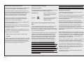
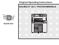
Original Operating Instructions
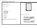
BAUMCUT 26.4 PROGRAMMABLE
D
7 8
i
4
5
1 2
9
6 x
3
C 0
PROGRAMMABLE
BAUM USA
Index
page
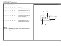
Control Panel / Operating Elements ............................................................... E - 4
Explanation of Pictographs on the Display ...................................................... E - 5
Chapter Survey ............................................................................................... E - 6
Introduction ..................................................................................................... E - 7
Technical Data/Machine Layout/Transport and Installation .................... K1 - 1
of the Machine/Safety Relevant Machine Elements ...................................... K1 - 1
Machine Layout ............................................................................................ K1 - 2
Plan .............................................................................................................. K1 - 3
Transport and Installation of the Machine ..................................................... K1 - 4
Place of Installation ...................................................................................... K1 - 4
After the Installation of the Machine .............................................................. K1 - 4
Power Supply ............................................................................................... K1 - 5
Type plate ..................................................................................................... K1 - 6
Safety Relevant Machine Elements .............................................................. K1 - 7
Accident prevention warning labels at BAUM cutters. ................................... K1 - 8
Safety Relevant Machine Elements .............................................................. K1 - 8
Safety Signs ................................................................................................. K1 - 9
Technical Data ............................................................................................ K1 - 10
Permissible Environmental and Operating Conditions ................................ K1 - 10
Hydraulic Data ............................................................................................ K1 - 10
Safety Precautions ..................................................................................... K1 - 10
Residual Risk ............................................................................................. K1 - 10
Technical Data ............................................................................................ K1 - 11
Safety ........................................................................................................... K2 - 1
Start Up ....................................................................................................... K3 - 1
Switching Machine ON ................................................................................. K3 - 2
Turning Machine OFF ................................................................................... K3 - 2
Measurement Display and Measurement System ........................................ K3 - 3
Manual Operation ....................................................................................... K4 - 1
Cutting Line Indicator, Mechanical with Clamp .............................................. K4 - 2
Cutting Line Indicator, Optical ....................................................................... K4 - 2
Setting of Measurements (Backgauge Movement) by Hand ......................... K4 - 2
Clamp Pressure Adjustment ......................................................................... K4 - 3
Setting the Clamping Time ........................................................................... K4 - 3
Clamping and Cutting ................................................................................... K4 - 3
Light Barrier .................................................................................................. K4 - 4
Continuation: Light Barrier ............................................................................ K4 - 5
E-2
Clamping with False Clamp Plate ................................................................. K4 - 6
Automatic Operation ............................................................................... K5A - 1
Introduction ................................................................................................. K5A - 2
Basic Displays ............................................................................................ K5A - 3
Basic Display: Program Data ...................................................................... K5A - 3
Contin.: Basic Display: Program Data ......................................................... K5A - 4
Basic Display: Program Information ........................................................... K5A - 5
Basic Display: Program Directory ............................................................... K5A - 6
Basic Display: Main Menu (Function Survey) .............................................. K5A - 7
Menu "Help": ............................................................................................... K5A - 7
Explanation of pictographs ......................................................................... K5A - 7
Cursor Movement in Basic Display ............................................................. K5A - 8
Automatic Backgauge Adjustment through Numerical Keyboard ................ K5A - 9
Deletion of a Wrong Input ......................................................................... K5A - 10
Moving Backgauge to a Nominal Position (Positioning) ............................ K5A - 10
Input Error: Value of Nom. Backgauge Position too Low/High .................. K5A - 10
Selection of a Free Program/Display of the Next Free Program ............... K5A - 11
Selecting a Program ................................................................................. K5A - 12
Continuing: Selecting a Program .............................................................. K5A - 13
Storage of Measurements ........................................................................ K5A - 14
Setting Up a Cutting Program, Example 1 ................................................ K5A - 15
Setting Up a Cutting Program, Example 2 ................................................ K5A - 16
Correction of an Input Error ...................................................................... K5A - 17
Automatic ON/OFF ................................................................................... K5A - 18
Running a Cutting Program ...................................................................... K5A - 19
Storing of Program Informations ............................................................... K5A - 20
Deletion of a Step Number........................................................................ K5A - 21
Deletion of One/Several Program(s) ......................................................... K5A - 22
Deletion of Complete Memory .................................................................. K5A - 23
Inserting of Measurements into a Program ............................................... K5A - 24
Storing of Measurements According to Printed Image .............................. K5A - 24
Calculator Functions ................................................................................. K5A - 25
Negative Sign ........................................................................................... K5A - 26
Using Backgauge Position of Calculations ............................................... K5A - 26
Machine Functions and Additional Functions (Menu Keys) ................ K5B - 1
Machine Function: Main Menu (Function Survey) ...................................... K5B - 2
Menu "Help": .............................................................................................. K5B - 2
Explanation of pictographs ........................................................................ K5B - 2
Service ...................................................................................................... K5B - 3
Index
Select Language/Measuring Unit ............................................................... K5B - 3
Knife Compensation ................................................................................. K5B - 4
Resting Time for Knife at BDC ................................................................... K5B - 5
Maintenance Cut Counter .......................................................................... K5B - 6
Preset Functions ....................................................................................... K5B - 7
Continuing: Preset Functions ..................................................................... K5B - 8
Adjustment of Display Contrast ................................................................. K5B - 9
Block Programming ................................................................................. K5B - 10
Variation 2 ................................................................................................ K5B - 10
(with edge trim preadjusting) ................................................................... K5B - 10
Variation 1 ................................................................................................ K5B - 10
Variation 3 ................................................................................................ K5B - 10
Attention! ................................................................................................. K5B - 12
Function "Help":Explanation of pictographs and description of functions . K5B - 12
Four trim cut ............................................................................................ K5B - 13
Four trim cut with labels ........................................................................... K5B - 14
Maintenance ................................................................................................ K8 - 1
Basic information about servicing and maintenance work ............................ K8 - 2
Menu Key: Additional Functions ............................................................ K5C - 1
Storage of Additional Functions with Cut Size ............................................ K5C - 2
Subsequent Storing of Additional Functions ............................................... K5C - 2
List of Additional Functions ........................................................................ K5C - 3
Menu Key: Auxiliary Functions .............................................................. K5D - 1
Cut and Record ......................................................................................... K5D - 2
Sheet Size Tables ...................................................................................... K5D - 2
Subtraction Repetition Unit ........................................................................ K5D - 3
Graphics OFF ............................................................................................ K5D - 3
Menu Key: Machine Parameters ............................................................ K5E - 1
Prepressure Time ...................................................................................... K5E - 2
Resting time for knife at BDC .................................................................... K5E - 2
Knife Change .............................................................................................. K6 - 1
Knife change ................................................................................................ K6 - 2
Changing of cutting stick .............................................................................. K6 - 5
Malfunctions/Breakdowns ......................................................................... K7 - 1
Electrical Malfunctions/Breakdowns ............................................................. K7 - 2
Start - Up Breakdown: Scan Reference Point/Auxiliary Mode ....................... K7 - 3
Mechanical Breakdown:Rupture of a Knife Bar/Clamp Recuperating Spring K7 - 4
E-3
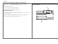
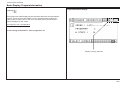
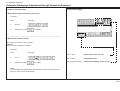
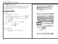
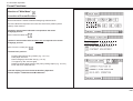
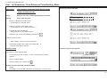
Control Panel / Operating Elements
D
7
8
9
i
4
5
6
1
2
3
x
C 0
PROGRAMMABLE
1
Automatic ON
Automatic OFF
Program Data
2
3
Machine Parameter
Subtraction
Clear input field
Auxiliary Program Functions
Enter
Decimal point
Additional Functions
Insert; subsequent insertion of
Cursor
(4 keys: right, left, up, down;
Center key: Additional cursor
motion; cursor in basic position
data
Program Information
Function Survey (Main Menu)
Numerical keyboard
Delete
Division
Correction (of stored data)
Program Directory
Program Selection
Display
2
Turning knob for backgauge movement
(Electronic hand wheel)
3
Switch for optical cutting line
indicator and table light ON
Multiplication
Equal key
Addition
Transfer key: Transfer backgauge
pos. into input field
E-4
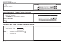
1
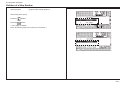
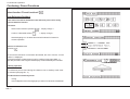
Explanation of Pictographs on the Display
Pre clamping time
Hand wheel/electr. hand wheel
Order
Clamping force grade
Sensor key forward
Look for order
Feed mark
Sensor key reverse
Select program number
Programmable ejector
Cut buttons
Delete program number
External special functions
Marking during cutting
Under cut
Program functions
Actual to nominal position
Plus/positive sign
Program parameters
Automatical ejector off
Minus/negative sign
Various auxiliary functions
Function survey/Memory
Change contrast of display
Free program
function survey/Language
Spare cursor
Paper sizes
Function survey/Service
Original sheet size/Block programming
Enter
Function survey/Block programming
Label size/Block programming
Correction
Function survey/preset functions
Edge trim/Block programming
Delete
Machine parameters
( - ) Subtraction repetition unit
Insert
Number (1 - 0)
Grafics off
Key Equal
Clear/Clear input
Block programming
Key Positioning (2x Ist-Gleich)
Service
Knife/Lower dead point time
Program selection
Call sevice
Program data display
Error
Program information
Reference run
Function survey
Correct basic position
Program directory
Correct actual position
Nominal position
German (Language)
Key Cursor right/left
Please wait
Key Cursor up/down
Clear/Exit
Help
Spare cursor
Key Cursor Home
Main drive unit not ready
Numerical keyboard
Press pedal
E-5
Chapter Survey
Chapter Survey
Page
1.0 Technical Data/Machine Layout/Transport and Installation of Machine/
Safety Relevant Machine Elements ................................................................................ K1 - 1
2.0 Safety.............................................................................................................................. K2 - 1
3.0 Start Up ........................................................................................................................... K3 - 1
4.0 Manual Operation ........................................................................................................... K4 - 1
5.0 Automatic Operation .................................................................................................... K5A - 1
6.0 Knife Change .................................................................................................................. K6 - 1
7.0 Malfunctions/Breakdowns ............................................................................................... K7 - 1
8.0 Maintenance ................................................................................................................... K8 - 1
E-6
Introduction
BAUM cutting machines form a part of the wide range of products manufactured by the BAUM company.
Decades of experience in constructing high speed cutting machines and peripheral equipment, together with state-of-the-art engineering and manufacturing procedures,
careful testing and highest quality standards ensure the reliability and performance of your BAUM machine.
Please pay special attention to the following information:
•
The section on “Safety” in the operating instructions!
•
The operating instructions are not meant as an instruction for repair. Such work should be carried out by BAUM service, exclusively.
•
Use only original BAUM spare parts; indicate type and machine number in your requests.
•
Illustrations in the operating instructions/spare parts catalogue may deviate from the real design. Nevertheless, the information given is not altered by this.
•
The use of the aids mentioned in the operting instructions, such as oils, greases, cleansing agents etc. refers to the preparation date of these instructions.
The complete Technical Documentation should always be kept near the machine.
We recommend to read these operating instructions carefully prior to commissioning the machine, because we shall not be liable for any damage or breakdown resulting
from any nonobservance of these operating instructions.
Copyright
All rights reserved for this document. No part of it may be duplicated or brought to the notice of other people in any form without our express consent.
Any violation engages to damages.
The Operating Instructions must be stored for future use!
E-7
E-8
1.0
Technical Data / Machine Layout / Transport and Installation
of the Machine / Safety Relevant Machine Elements
K1 - 1
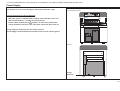
1.0 Technical Data/Machine Layout/Transport and Installation of the Machine/Safety Relevant Machine Elements
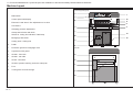
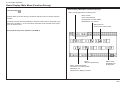
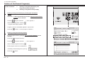
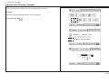
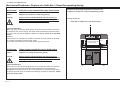
Machine Layout
Front side (operating side)
2
D
7
i
4
1
8
9
5
6
2
3
x
C 0
1
Main switch
2
Control panel with display
3
Electronic hand wheel / fine adjustment of cut size
4
Cut buttons
5
Clamping pressure adjustment
6
Clamp and knife bar with knife
7
Switch for cutting line indicator/ Table lamp
8
Backgauge with rakes
9
Cutting stick / Cutting line
10
Pedal
11
Protective guard for backgauge drive
12
Light barrier with guard
13
Guards - front side
14
Guards - rear side
15
Guard - rear table
16
Guard to prevent reaching under the clamp bar
17
Foot
18
Turning knob for knife change
PROGRAMMABLE
3
12
12
6
9
4
4
1
13
18
10
5
17
Rear side
16
15
11
8
14
K1 - 2
7
1.0 Technical Data/Machine Layout/Transport and Installation of the Machine/Safety Relevant Machine Elements
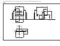
Plan
Dimensions in mm!
K1 - 3
1.0 Technical Data/Machine Layout/Transport and Installation of the Machine/Safety Relevant Machine Elements
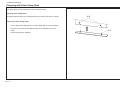
Transport and Installation of the Machine
After Unloading
•
•
•
Remove all packing and wrapping material
Check machine and accessories for damages
Check for missing parts
Have the machine installed by BAUM service personnel, exclusively!
In Case of Complaints
The installation of the machine requires special skills which can be
guaranteed only by especially trained experts of BAUM agencies.
Arbitrary working on the machine may damage the machine itself or other
material property of the user or cause accident endangering life and limb
of the staff.
Immediately send written note to:
•
•
•
Railway or shipping company
Insurance company
BAUM / Agency
The machine must be unpacked, moved, transferred and installed by
authorized BAUM Service Technicians only. Dangers might arise from the
machine itself or from its packing if it is unpacked, moved, transferred or
installed with unsuitable devices.
Place of Installation
While the machine is unpacked, moved, transferred and installed, no
other persons must be present in the range of the machine or its packing.
•
•
The BAUM Service Technician must also take care that no unauthorized
persons work at the machine, its packing or the installation equipment.
•
•
•
The location must meet the following requirements:
Vibration free location
Even concrete flooring, concrete property class min. (N/mm²) according to
eurocode 2: C20/25 or according to DIN1045: B 25.
Observe carrying capacity!
Avoid possible accidents of operator by uneven flooring
Adhere to minimum distance from buildings or peripheral equipment (see
plan)
After the Installation of the Machine
1.
2.
3.
4.
K1 - 4
Remove anti rust paint (agent: kerosene, gasoline) from the machine on
the site of installation
Note:
Do not use any sharp tools to remove anti-rust paint!
Clean plastic covers only with plastic cleansing agent
Final check according to check list
Have handover signed
1.0 Technical Data/Machine Layout/Transport and Installation of the Machine/Safety Relevant Machine Elements
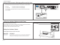
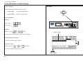
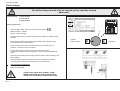
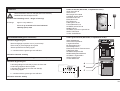
Power Supply
The machine is to be connected by an authorized electrician, only!
Front side (Operating side)
D
7
i
4
1
Connect machine according to diagram!
•
When the system is operated with residual current breaker, use a residual current breaker ( > 30 mA ) for each machine!
•
All the cables marked with a
symbol, as well as any cables with
orange sheath are still alive even if the main switch has been shut off.
8
9
5
6
2
3
x
C 0
PROGRAMMABLE
Energy supply is made from the rear of the machine.
Power supply is located within the connection box; access via front guard.
Rear side
Energy
lead wire
K1 - 5
1.0 Technical Data/Machine Layout/Transport and Installation of the Machine/Safety Relevant Machine Elements
Type Plates
Type plate
Type plate
The machine designation including
•
manufacturer‘s address
•
model
•
machine number
•
date of fabrication
•
electric. equipment
Adolf Mohr
Maschinenfabrik
65719 Hofheim/Ts
Germany
Model
is indicated on the machine type plate.
K1 - 6
Serial No.
/PE AC
mfd.
V
Hz
A
1.0 Technical Data/Machine Layout/Transport and Installation of Machine/Safety Relevant Machine Elements
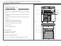
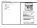
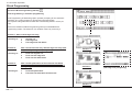
Safety Relevant Machine Elements
Front side (operating side)
1
Main switch
2
Light barrier (20 - channel)
Capacity to recognize object: 25 mm
Min. distance of light barrier:
Total reaction time of system:
328 mm
3
< 120 ms
Knife bar spring assembly (mechanical lock against lowering of knife
bar)
4
Clamping bar spring assembly (mechanical lock against lowering of
clamping bar)
5
Two-handed cutting release with simultaneity control and anti-repeat
circuit
6
Electronics:
- Failsafe control by multiple self-diagnostics
- Machine self-diagnostics with error message
7
Guard to prevent reaching under the clamp bar
8
Rear-table guard
9
Guard of backgauge drive unit
D
7
i
4
1
8
9
5
6
2
3
x
C 0
PROGRAMMABLE
2
2
3
5
4
6
Rear side
7
Safety Auxiliary Tools
8
Angle for jogging the cutting material
Knife protection for knife change
9
Working Area of Operating Personnel
Working area is the complete front side (operating side) of the machine.
K1 - 7
1.0 Technical Data/Machine Layout/Transport and Installation of the Machine/Safety Relevant Machine Elements
Safety Relevant Machine Elements
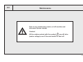
Accident prevention warning labels at BAUM cutters.
Placement of the warning labels
Placement of the warning label
Label 1 (1x):
Label 2 (1x):
Label 3 (2x):
Warning labels are of little value if the foreseeable user cannot see them at
the appropriate time, i.e., before he or she encounters the hazard. Labels,
therefore, should be placed near the hazard and in such a position that the
worker will see and be able to read them before encountering the hazard.
Location:
At backgauge drive
guard.
BAUM order no.:
281267
Location:
At the lower front of the
cutter.
BAUM order no.:
281266
Location:
At the front and the rear
of the cutter.
BAUM order no.:
281268
Durability
Accident prevention warning labels should be kept sufficiently durable to
remain easily readable at an appropriate distance for a reasonable life.
K1 - 8
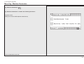
Safety Signs
Safety Signs / Warning Signs
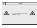
In order to ensure maximum safety the machine / system is provided with safety
signs. Safety signs are either standardized safety signs warning of risks or
danger, or warning signs alerting the operating or service staff of
- any forbidden actions at the machine / system,
and/or
- informing about any load limits, such as the max. carrying capacity of the
machine and/or its load carrying unit.
Safety signs must be durable and have to be kept in a perfectly visible condition.
Warning signs ought to be visible in good time even from a great distance.
The machine /system may be provided with the following safety or warning
signs on various components of the machine:
Warning: Dangerous voltage
(e. g. electrical connector boxes, control boxes/control
cabinets of machine control systems)
K1 - 9
1.0 Technical Data/Machine Layout/Transport and Installation of Machine/Safety Relevant Machine Elements
Technical Data
Permissible Environmental and Operating Conditions
•
Observe the procedures described in case of malfunctions and the mainte
nance intervals indicated.
Operate the machine in closed areas, exclusively!
Air humidity:
Ambient air temperature:
35% - 95% (non condensing)
+5°C - +40°C
Hydraulic Data
Hydraulic pressure, max.:
160 bars!
Safety Precautions
•
Minimum age of operating staff: 18 years!
•
Before starting any work at the machine - read safety section of manual!
•
During the working process no other persons must enter the working area or
interfere with the process
•
Use the angle included in the scope of supply for positioning the cutting
material
•
Knife change may only be carried out by personnel especially trained for this
purpose
•
Utmost care must be taken when handling the knife!! Always deposit or
transport the knife in the knife case.
•
Use only undamaged and sharp knives!
•
During the cutting no tool or objects - such as e.g. T-wrench must be on the
machine table in order to prevent them from reaching unintentionally under
the clamp and/or knife during the cutting process. There is a high risk of
injuries due to little parts of the knife edge coming off in splinters.
K1 - 10
Residual Risk
In spite of the safety measures provided by construction there remains a
residual risk when operating the machine.
This residual risk mainly concerns the danger of contusions and cuts during
clamping, cutting or knife change as well as handling the cutting material in
general, if the necessary care is neglected.
The parts especially affected are the upper extremities of the operating staff especially their arms and hands.
Special care must be taken when performing the knife change. It may only be
carried out by personnel especially trained for this job!
During knife change no other persons must enter the working area of the
machine (cuts)!
1.0 Technical Data/Machine Layout/Transport and Installation of the Machine/Safety Relevant Machine Elements
Technical Data
Cutting width
67 cm / 26,38"
Clamp opening
8 cm / 3,15"
Feed depth
67 cm / 26,38"
Voltage supply (3 phase) 200 - 240, 50/60Hz
Fusing
3 x 25A
Voltage supply (3 phase) 360 - 420V, 50/60Hz
Power requirement (main motor):
Single phase A C
3 phase
2,2 kW / 3,1 H.P.
2,4 kW / 3,4 H.P.
Net weight
620 kg / 1367 lbs
Width
125 cm / 49,2"
Length
182,5 cm / 71,85"
Height
151,5 cm / 59,64"
Front table length
67 cm / 26,38"
Table height
90 cm / 35,43"
Clamp pressure, min.
max.
200 daN / 440 lbs
1500 daN / 3300 lbs
Knife thickness
9,7 mm / 0,38"
Grinding reserve, max.
2,2 cm / 0,86"
Noise emission
Metering of noise level according to DIN EN 13023, LpA (dB):
Smallest cut
without false clamp, min.
with false clamp, min.
1,5 cm / 0,6"
5 cm / 1,96"
76,5 with 300 cuts/hour (manual feeding)
79,5 with 600 cuts/hour (manual feeding)
Backgauge speed
0 - 7 cm/sek.
Extraneous and room noise correction has been carried out.
Knife speed/min.
20
Fusing
3 x 16A
Voltage supply single phase AC (200 - 240, 50Hz)
Fusing
1 x 32A
Voltage supply single phase AC (210 - 240, 60Hz)
Fusing
1 x 32A
Attention!
The wire cross section of the main power supply according to the countrys regulations.
Same regulations according the plug connectors.
daN = kp
K1 - 11
K1 - 12
2.0
Safety
Any person on the user´s premises concerned with
the operation, maintenance and repair of the machine, resp., is expected to have read and comprehended the section on "Safety"
K2 - 1
Foreword to the operating instructions
Fundamental safety instructions
These operating instructions are designed to familiarize the
user with the machine/plant and its designated use.
Warning and symbols
The instruction manual contains inportant information on
how to operate the machine/plant safely, properly and most
efficiently. Observing these instructions helps to avoid
danger, to reduce repair costs and downtimes and to
increase the reliability and life of the machine/plant.
The instruction manual is to be supplemented by the
respective national rules and regulations for accident
prevention and environmental protection.
The operating instructions must always be available wherever the machine/plant is in use.
These operating instructions must be read and applied by
any persons in charge of carrying out work with and on the
machine/plant such as
- operation including setting up, troubleshooting in the
course of work, evacuation of production waste, care and
disposal of fuels and consumables.
-
maintenance (servicing, inspection, repair) and/or
-
Transport
In addition to the operating instructions and to the mandatory rules and regulations for accident prevention and environmental protection in the country and place of use of the
machine/plant, the generally recognized technical rules for
safe and proper working must also be observed.
K2 - 2
The following signs and designations are used in the manual
to designate instructions of particular importance
Note/Attention:
Symbol:
refers to special information on
how to use the machine/plant
most efficiently
refers to orders and prohibitions
designed prevent injury or
extensive damage
Basic operation and designated use of the machine/
plant
The machine/plant has been built in accordance with stateof-the-art standards and the recognized safety rules.
Nevertheless, its use may constitute a risk to life and limb of
the user or of third parties, or cause damage to the machine
and to other material property.
The machine/plant must only be used in technically perfect
condition in accordance with its designated use and the
instructions set out in the operating manual, and only by
safety-conscious persons who are fully aware of the risks
involved in operating the machine/plant. Any functional
disorders, especially those affecting the safety of the
machine/plant, should therefore be rectified immediately.
The machine is meant exclusively for cutting leaved
materials, such as paper, cardboard or plastic films.
Any other use, such as the cutting of harder, especially thicker
materials and materials of other kinds, as well as any further
use beyond this, is considered as not being in accordance
with the designated use. Such materials may be processed
only according to prior agreement with the manufacturer of this
machine and after a written confirmation by the manufacturer.
The manufacturer/supplier cannot be held liable for any
damage resulting from such use. The risk of such misuse lies
entirely with the user.
Operating the machine within the limits of its designated use
also involves the instructions set out in the operating manual
and complying with the inspection and maintenance directives.
Organizational measures
The operating instructions must always be at hand at the
place of use of the machine/plant.
In addition to the operating instructions, observe and instruct
the user in all other generally applicable legal and other
mandatory regulations relevant to accident prevention and
environmental protection.
These compulsory regulations may also deal with the
handling of hazardous substances, issuing and/or wearing
of personal protective equipment, or traffic regulations.
The operating instructions must be supplemented by
instructions covering the duties involved in supervising and
notifying, special organizational features, such as job
organization, working sequences or the personnel entrusted
with the work.
Personnel entrusted with work on the machine must have
read the operating instructions and in particular the chapter
on safety before beginning work. Reading the instructions
after work has begun is too late. This applies especially to
persons working only ocassionally on the machine, e. g.
during setting up or maintenance.
Check - at least from time to time - whether the personnel is
carrying out the work in compliance with the operating
instructions and paying attention to risks and safety factors.
For reasons of security, long hair must be tied back or
otherwise secured, garments must be close-fitting and no
jewellery - such as rings - may be worn. Injury may result
from being caught up in the machinery or from rings
catching on moving parts.
Use protective wherever required by equipment by the
circumstances or by law.
Observe all safety instructions and warnings attached to the
machine/plant.
See to it that safety instructions and warnings attached to the
machine are always complete and perfectly legible.
In the event of safety-relevant modifications or changes in the
behaviour of the machine/plant during operation, stop the
machine/plant immediately and report the malfunction to the
competent authority/person.
Never make any modifications, additions or conversions which
might affect safety without the supplier´s approval. This also
applies to the installation and adjustment of safety devices and
valves as well as to welding work on load-bearing elements.
Spare parts must comply with then technical requirements
specified by the manufacturer. Spare parts from original
equipment manufacturers can be relied to do so.
Never modify the software of programmable control systems.
Replace hydraulic hoses within stipulated and appropriate
intervals even if no safety-relevant defects have been detected.
Adhere to prescribed intervals or those specified in the
operating instructions for routine checks and inspections.
Selection and qualification of personnel - Basic responsibilities
Any work on and with the machine/plant must be executed by
reliable personnel only. Statutory minimum age limits must be
observed.
Employ only trained or instructed staff and set out clearly the
individual responsibilities of the personnel for operation, setup, maintenance and repair.
Make sure that only authorized personnel works on or with the
machine.
Define the machine operator´s responsibilities - also with
regard to observing traffic regulations - giving the operator the
authority to refuse instructions by third parties that are contrary
to safety.
Do not allow persons to be trained or instructed or persons
taking part in a general training course to work on or with the
machine/plant without being permanently supervised by an
experienced person.
Work on the electrical system and equipment of the machine/
plant must be carried out only by a skilled electrician or by
instructed persons under the supervision and guidance of a
skilled electrician and in accordance with electrical engineering rules and regulations.
Work on the hydraulic system must be carried out only by
personnel with special knowledge and experience of hydraulic
equipment.
Safety instructions governing specific operational
phases
Standard operation
Avoid any operational mode that might prejudicial to safety.
Take the necessary precautions to ensure that the machine is
used only when in a safe and reliable state.
Operative machine only if all protective and safety-oriented
devices, such as removable safety devices, emergency shutoff equipment, sound-proofing elements and exhausters, are
in place and fully functional.
Check the machine/plant at least once per working shift for
obvious damage and defects. Report any changes (incl.
changes in the machine´s working behaviour) to the competent organization/person immediately. If necessary, stop the
machine immediately and lock it.
In the event of malfunctions, stop the machine/plant immediately and lock it. Have any defects rectified immediately.
During start-up and shut-down procedures always watch the
indicators in accordance with the operating instructions.
Before starting up or setting the machine/plant in motion,
make sure that nobody is at risk.
Never switch off or remove suction and ventilation devices
when the machine is in operation.
Special work in conjunction with utilization of the machine/plant and maintenance and repairs during operation;
disposal of parts and consumables
Observe the adjusting , maintenance and inspection activities
and intervals set out in the operating instructions, including
information on the replacement of parts and equipment. These
activities may be executed by skilled personnel only.
Brief operating personnel before beginning special operations
and maintenance work, and appoint a person to supervise the
activities.
In any work concerning the operation, conversion or adjustment of the machine and its safety-oriented devices or any
work related to maintenance, inspection and repair, always
observe the start-up and shut-down procedures set out in the
operating instructions and the information on maintenance
work.
Ensure that the maintenance area is adequately secured.
If the machine/plant is completely shut-down for maintenance
and repair work, it must be secured against inadvertent
starting by:
- locking the principal control elements and removing the
ignition key and/or
- attaching a warning sign to the main switch.
Clean the machine, especially connections and threaded
unions, of any traces of oil or presevatives before carrying out
maintenance/repair. Never use aggressive detergents. Use
lint-free cleaning rags.
Always tighten any screwed connections that have been
loosened during maintenance and repair.
Any safety devices removed for set-up, maintenance or repair
purposes must be refitted and checked immediately upon
completion of the maintenance and repair work.
Ensure that all consumables and replaced parts are disposed
of safely and with minimum environmental impact.
K2 - 3
Warning of special dangers
Any procedure impairing the safety at the machine must be
refrained from. In particular do not
- reach into the range of knife and clamp, use auxiliary
tools (e. g. material gauge)
- reach into the range between clamp and cutting material
gauge (backgauge with rake) on the machine rear table
- with Autotrim function:
entering the opened table crack to remove residual cuttings.
Only do that with the machine switched off.
- at machines with attached and/or separately installed
peripheral equipment with lifting/swivelling/moving and/or
clamping function:
do not enter or reach into the danger zone during movement
(provide guard rail)
- The knife may only be changed by personnel especially
instructed for this purpose
Electrical energy
Use only original fuses with the specified current rating.
Switch off the machine/plant immediately if trouble occurs in
the electrical system.
Work on the electrical system or equipment may only be
carried out by a skilled electrician himself or by specially
instructed personnel under the control and supervision of
such electrician and in accordance with the applicable
electrical engineering rules.
If provided for in the regulations, the power supply to parts
of machines and plants, on which inspection, maintenance
and repair work is to be carried out must be cut off. Before
starting any work, check the de-energized parts for the
presence of power and ground or short-circuit them in
addition to insulating adjacent live parts and elements.
The electrical equipment of machines/plants is to be inspected and checked at regular intervals. Defects such as loose
connections or scorched cables must be rectified immediately.
leaks and obvious damage. Repair damage immediately.
Splashed oil may cause injury and fire.
Depressurize all systems sections and pressure pipes
(hydraulic system, compressed-air system.
Necessary work on live parts and elements must be carried
out only in the presence of a second person who can cut off
the power supply in case of danger by actuating the emergency shut-off or main power switch. Secure the working
area with a red-and-white safety chain and a warning sign.
Use insulated tools only.
Hydraulic and compressed-air lines must be laid and fitted
properly. Ensure that no connections are interchanged. The
fittings, lenghts and quality of the hoses must comply with
the technical requirements.
Before starting work on high-voltage assemblies and after
cutting out the power supply, the feeder cable must be
grounded and components, such as capacitors, shortcircuited with a grounding rod.
Gas, dust, steam and smoke
Carry out welding , flame-cutting and grinding work on the
machine/plant only if this has been expressly authorized, as
there may be a risk of explosion and fire.
Before carrying out welding, flame-cutting and grinding
operations, clean the machine/plant and its surroundings
from dust and other inflammable substances and make sure
that the premises are adequately ventilated (risk of explosion).
Observe any existing national regulations if work is to be
carried out in narrow rooms.
Hydraulic and pneumatic equipment
Work on hydraulic equipment may be carried out only by
persons having special knowledge and experience in
hydraulic systems.
The pneumatic equipment at the machine must only be
connected to plant compressed-air supply system secured
against overpressure.
Check all lines, hoses and screwed connections regularly for
K2 - 4
Oil, grease and other chemical substances
When handling oil, grease and other chemical substances,
observe the product-related safety regulations.
Be careful when handling hot consumables (risk of burning
or scalding)
3.0
Start Up
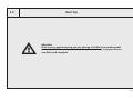
Attention!
Prior to any commissioning and any change of shifts the operating staff
has to check if the safety-related machine elements are in proper service
condition and complete.
K3 - 1
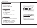
3.0 Start Up
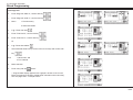
Switching Machine ON
Attention!
Prior to any commissioning and any change of shifts
the operating staff has to check if the safety related
machine elements are in proper service condition and
complete.
D
7
i
4
1
8
9
5
6
2
3
x
C 0
PROGRAMMABLE
1.
Turn main switch (2) from "0" to "I"
< Control voltage is switched on.
After several seconds display shows Program data display >
Turning Machine OFF
1.
Wait until automatic operations have ended.
2.
Turn main switch from " I " to "0" position
to prevent a start-up of the machine:
Place padlock into main switch, lock it and remove the key.
K3 - 2
2
3.0 Start Up
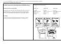
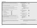
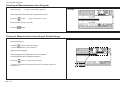
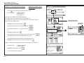
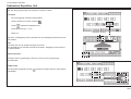
Measurement Display and Measurement System
After switching on, the "Program Data Display"* appears on the screen.
Program Data Display
It shows among other things...
A
on the upper screen (A): ACTUAL POSITION
on the lower screen (Nominal position input field, B):
NOMINAL POSITION INPUT
The actual position (A) shows the real backgauge position in mm, cm, inches or
sun = 1/10 shaku (Japan).
Measurement system can be changed - see "Function Survey, page K5B - 3"
* If this fails, see Malfunctions/Breakdowns, page K7 - 5.
B
K3 - 3
K3 - 4
4.0
Manual Operation
K4 - 1
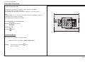
4.0 Manual Operation
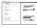
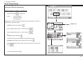
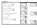
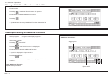
Setting of Measurements (Backgauge Movement) by Hand
1.
Press electronical hand wheel and hold it in this position; turn hand wheel
to the left
or to the right
D
7
8
i
4
5
6
1
2
3
= forward movement of the backgauge
= reverse movement of the backgauge
9
x
C 0
PROGRAMMABLE
The backgauge speed gets faster by turning the electronical hand wheel
to the left/right .
3
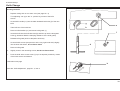
Cutting Line Indicator, Mechanical with Clamp
Lower clamp with pedal onto stock:
The front edge (a) of the clamp is identical to the cutting line and can be used as
cutting line indicator. Clamp can be stopped in any position.
Max pressure with fully activated pedal: 30 daN
8
D
7
8
9
4
5
6
1
2
3
x
C 0
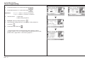
Cutting Line Indicator, Optical
Actuate toggle switch (8) at main switch plate
Upper position:
middle position:
lower position:
K4 - 2
Table light ON
"0" - position
Optical cutting line indicator ON. A thin light line indicates the
cutting line; the table light is switched off at that moment.
PROGRAMMABLE
RAMMABLE
a
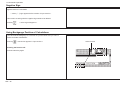
4.0 Manual Operation
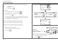
Clamping and Cutting
Starting the cut:
D
7
i
4
1
8
9
5
6
2
3
x
C 0
PROGRAMMABLE
Push both cut buttons (4) simultaneously.
(Hold buttons until knife is on upstroke)!
Interrupting the cut:
Release one or both cut buttons
(clamp and knife stop immediately and move back to initial position).
Continuing the cut:
4
Release and simultaneously push both cut buttons.
5
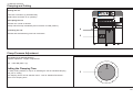
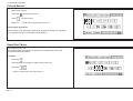
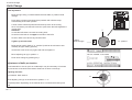
Clamp Pressure Adjustment
Turn knob (5) to desired position
Stepless adjustment - ranges of adjustment:
200 - 1500 daN (daN = kp)
50
0
150
50
5
12
750
1000
For bulky cutting material, it may be of advantage to set an extended clamping
time prior to cutting.
The clamping time is set via selection menu - refer to "Machine Parameter Select "Pre-clamping time"
0
Setting the Clamping Time
K4 - 3
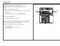
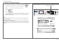
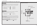
4.0 Manual Operation
Light Barrier
The lightbarrier (17) forms a curtain of invisible beams in front of the knife.
Any obstacle in the beams will stop clamping and cutting.
In that case the clamp can still be lowered with the pedal (indication of
cutting line).
D
7
i
4
1
8
9
5
6
2
3
x
C 0
Interference into the light curtain causes:
•
•
•
clamping bar and knive stopped instantaneously and move back to initial
position
a beep sound
the monitor to display the message: CUT INTERRUPTED
To continue the cutting process:
Release cut buttons; trigger the cut again
The light barrier used is an infrared light barrier with twenty channels and a selfinspection system. This monitoring is indicated optically in the left-hand light
barrier (receiver side) by LEDs as part of a display unit.
The machine control system generates a test signal whenever ..
•
•
•
K4 - 4
a cut is released
the lower dead centre of the knife is reached
cutting is interrupted
PROGRAMMABLE
17
17
4.0 Manual Operation
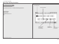
Continuation: Light Barrier
Meaning of LEDs in display unit
Display unit in the left-hand part of the light barrier (receiver side):
D1
D2
D3
D4
D5
D6
Meaning
_________________________________________________________________
on
on
on
on
off
off
Protect. area „unobstructed“, light
reception excellent
off
on
on
on
off
off
Protect. area „unobstructed“, light
reception good
off
off
on
on
off
off
Protect. area „unobstructed“, light
reception just sufficient
D6
Protect. area obstructed or a test is
performed
D5
on
off
on
off
flashing
off
off
on
on
off
off
on
on
Protect. area has never been
unobstructed since Voltage ON
off
off
on
on
Error
D2
D1
D4
D3
Attention!
In the case of a breakdown of the display unit the safety function of the
light barrier will not be impaired!
K4 - 5
4.0 Manual Operation
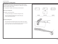
Clamping with False Clamp Plate
The clamp plate avoids clamping marks on sensitive stock.
Attaching false clamp plate:
Push plate against clamp from underneath until you hear guide pins (6.1)snap.
6.2
Removing of false clamp plate:
1.
Lower clamp with pedal approx. 2" above table and fix it in this position.
2.
Press two screw drivers simultaneously into the drillings (6.2) in the
clamp.
False clamp plate is dropped!
K4 - 6
6.1
5.0
Automatic Operation
K5A - 1
Introduction
Functions of the menu keys*
A position (cut size) entered via numerical keyboard can be stored permanently.
Any number of cut sizes necessary for the processing of a pile of material can be input
and stored.
All the data (cut sizes, information, additional functions) concerning one particular order
can be stored under one program number.
Cut sizes can also be stored automatically when a cut is triggered.
A programmable automatic function enables the advance movement of the cutting
material to the next position stored once a cut has been performed.
The machine is provided with a subtraction repeat unit to process invariable cutting
sequences in a fast and simple way.
All the data and information are shown on four basic displays:
1.
Program Data
2.
Program Information
3.
Main menu (Function Survey )
4.
Program Directory
Program Data display and Program Information display are meant for the input of cut
sizes or the display of additional information concerning a particular program.
Operator prompting on all display levels and input of clear text via softkey input (function
pictographs (symbols) on the display)
The Program Directory display shows all the assigned programs contained in the memory.
By means of the Function Survey display it is possible to select various machine
functions.
The keyboard of the operating panel with its menu keys makes it possible to store additional functions for individual cut sizes, which accompany and facilitate or accelerate the
working sequence.
Key "Main menu (Function Survey)"
Select language
Select measuring unit
Service
Knife compensation
Resting time for knife at BDC
Maintenance cut counter
Preset functions
Reference run
Adjustment of display contrast
Correction of current position
Block programming
Help
Menu key "Additional Functions"
Automatic ejector OFF
Jogging mark
Help
Menu key "Machine Parameters"
Pre-pressing time
Resting time for knife at BDC
Menu key "Auxiliary Functions"
Programming with cut
Sheet size tables
Subtraction repetition unit
Graphics OFF
Help
Direct keys: Automatic Function ON, Automatic Function OFF, Program Selection,
Numerical Keyboard (with 4 fundamental operations of arithmetic),
Correction, Insert, Delete, Store, Cursor Keys, Backgauge Movement with
Electronical Hand Wheel
* Technical alterations reserved!
K5A - 2
5.0 Automatic Operation
Basic Displays
1.
Program Data:
key
3.
Main Menu (Function Survey):
key
2.
Program Information:
key
4.
Program Directory:
key
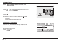
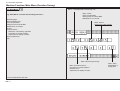
Basic Display: Program Data
Press key
< display shows program data display:(appears automatically after start-up*)
6
Explanation of Program-Data-display:
1
Program head (menu pictograph, program number (P: 1A) with memory
segment (S: 0) designation A )
2
Data section (3 step number visible on one page
3
Input section
4
Size display
5
Display of additional functions stored with step number
6
Status display (current machine function)
7
Display section Additional Function (after selection
8
Pictographs for user prompting (possible operating functions)
9
Current programming function with pictograph
10
Rolling bar (movement by cursor keys)
10
1
4
5
2
9
8
3
7
* If this fails, see "Malfunctions/Breakdowns, page K7 - 2"
K5A - 3
5.0 Automatic Operation
Contin.: Basic Display: Program Data
Conc. 1
Program Head shows:
Conc. 5
P:
Program number of indicated program with memory segment
e.g. 1A = program 1, memory segment A and program
protection (asterisk)
S:
Quantity of step numbers assigned by the program
Display of Additional functions
Display of the pictograph/s representing the Additional function/s
Conc. 6
Status display "Actual machine function"
Display of the pictograph representing the actual machine function
Conc. 2
Conc. 3
Program Data section shows:
e.g. 1
step number of program (with abbrev. for particular additional functions such as Eltrotact
etc.)
Pictograph(s)
additional function(s) stored:
Display of pictograph/s (symbol(s) of additional
function(s) stored
Conc. 7
Display section "Additional function"
Indication of the additional function to be stored after function has
been selected from menu.
Conc. 8
Pictographs user prompting
Indication of possible operating functions in the current menu
image
Input section shows:
Conc. 9
Actual programming function with pictograph
Data (cut size)/arithmetic functions entered
Indication of current programming function as a plain text and as
a pictograph
Conc. 4
"Position display“ section shows:
Conc. 10
K5A - 4
ACTUAL POSITION
Actual backgauge position/measuring unit
NOMINAL POSITION
Indication of nominal position
Scroll bar
For paging through the actual menu image; movement by cursor
keys
5.0 Automatic Operation
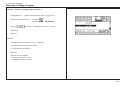
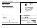
Basic Display: Program Information
Press key
Program Information display:
The Program Information display shows information about the currently selected
program. These pieces of information can be complemented by entering an
order number or order name in clear text. The alpha input is performed via a
keybord displayed on the screen.
Input capacity: max. 16 characters!
For the storing of information - refer to page K5A - 20.
display "memory segment"
K5A - 5
5.0 Automatic Operation
Basic Display: Program Directory
Basic display "Program Directory"
Press key
The program-survey shows all stored programs of the selected memory with the
following data:
(screen top): e.g.: - A -
= memory "A"
e.g.: 1/
= program number
e.g.: 1/1575
= order number/order name
PROGRAM NUMBER
5_VAC.
= display of number of the next free
program of the actual memory section
Note:
One "page" of the display can show a maximum of 4 programs.
If more than one page is used, you can turn to next page with cursor key
(observe rolling bar on display)
Other input modes in this display:
•
•
•
K5A - 6
program selection
program deletion
memory deletion
5.0 Automatic Operation
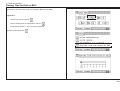
Basic Display: Main Menu (Function Survey)
Press menu key
Basic display "Main Menu" (Function Survey):
Menu "Language/Select measuring unit"
The Main Menu (Function Survey) contains a selection menu of various machine
functions.
It provides the user with the possibility to select functions which „accompany“ the
sequence of operation, i.e. such functions are either set at the start of the operation or in case of need.
Menu "Knife":
Knife compensation
Resting time for knife at BDC
Maintenance cut counter
Menu Service:
access with code number
Select and run any of the operation see K5B - 2
Menu:
"Block Programming"
Menu "Preset functions":
Correction of current position
Reference run
Adjustment of display contrast
Menu "Help":
Explanation of
pictographs
K5A - 7
5.0 Automatic Operation
Cursor Movement in Basic Display
Cursor = indicator
Cursor keys
The basic displays contain two kinds of cursor :
A.
Cursor "step"
( in program data section)
B.
Cursor "input"
(flashes in input section)
Cursor movement:
Meaning:
Cursor "step":
Cursor "input":
D
7
i
4
5
6
1
2
8
3
9
x
C 0
PROGRAMMABLE
Operation
pressing of keys
or
once
Cursor "step"
< cursor moves to next step (up or down) or input digit >
pressing of keys constantly:
< cursor moves constantly up/down >
only cursor "step":
if together with key
or
key
is pressed
< cursor will "jump" to first or last step >
Cursor "input"
K5A - 8
5.0 Automatic Operation
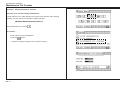
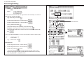
Automatic Backgauge Adjustment through Numerical Keyboard
Program data display:
Conditions: Automatic OFF
A Measurement input with metric system (cm)
Example:
Size
Key input
1.
30,735
2.
Positioning, press
2 x shortly
________________________________________________________________
B Measurement input in inches
Same way of input as for metric system
however
value in inches entered as a fraction:
Example:
Size
Key input
1.
12 1/2"
2.
Positioning, press
2 x shortly
after 1. input:
input section shows 30.735
after 2. input :
backgauge moves
after backgauge stops:
measurement display shows 30.735
Note:
For whole sizes (no digits behind decimal point) zeroes do not have to be
keyed in. This is done automatically.
K5A - 9
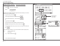
5.0 Automatic Operation
Deletion of a Wrong Input
Press
< input section is deleted >
Moving Backgauge to a Nominal Position (Positioning)
1.
Enter nominal position
2.
Press
twice shortly
< backgauge moves to nom. pos. forward or backward >
Deletion of a wrong input
Press
Input Error: Value of Nom. Backgauge Position too Low/High
If a nominal size is inserted which cannot be reached by the backgauge the
following reaction will be caused:
< a beep will sound - display:
Remedy:
K5A - 10
SIZE ERROR
1.
Press any key on numerical keyboard e.g.:
2.
Insert correct size
5.0 Automatic Operation
Selection of a Free Program / Display of the Next Free Program
Display (example):
Possible in all 4 basic monitor displays!
1.
Press key
"Program Selection"
< Selection menu appears;
Assignment display in the right-hand section of the image: display of free
programs of selected memory segment A in % >
Make selection "Program Number":
2.
Press key
3.
Enter desired program number
4.
Press key
< Program Data display of the program appears >
or
5.
Select free program - press key
< next free program appears >
K5A - 11
5.0 Automatic Operation
Selecting a Program
Possible in all 4 basic monitor displays!
Example:
Two calling modes:
A.
According to program number
B.
According to order number/order name
A.
According to Program number:
1.
Press key
2.
Select "program number" with key
3.
Enter desired program number
4.
Press key
"Program selection"
< menu appears >
< program data display of selected program appears >
B.
According to order number:
Note:
Previous storing of order number/order name to a program is
conditional (see "Storing of program information", page K5A - 20)
1.
Press key
2.
Select
3.
Enter order number/order name via softkey selection
K5A - 12
"Program selection"
< menu appears >
"Order" < alpha keyboard appears on display >
5.0 Automatic Operation
Continuing: Selecting a Program
Select a character using the cursor keys (with the equal key
you
can jump over five characters in a line), then press cursor key
"Home" *
4.
Press key
5.
Press key
Numerical keyboard
< character is inserted into input section >
(multiply)
D
i
7 8 9
4 5 6 x
1 2 3
< the desired program (order) appears in the data section, the resp. order
number/order name is faded in. The fading in is automatically cleared
upon the next data input >
C 0
PROGRAMMABLE
* Note:
Input of order number/order name can be done by entering only a part of the
name or the number.
After pressing the "equal" key the computer will "search" for the desired order
according to the entered characters.
In case memory contains several orders with the same characters display will
show the next program number/name whose characters matches the entered
characters.
K5A - 13
5.0 Automatic Operation
Storage of Measurements
Only in Program data display!
1.
Select free program
2.
Enter desired size with numerical keyboard (e.g. size 23,5 cm)
3.
Press key
"Enter"
< beep sounds;
nominal position is on step 1 in program data section >:
Note:
Display can show up to 3 steps (lines). When entering step 4 former step 1 will
disappear into screen memory.
K5A - 14
5.0 Automatic Operation
Setting Up a Cutting Program, Example 1
Two side trim on size DIN A3
untrimmed size 31 x 43 cm
Cut sizes to be stored on program no. 2A
1.
2.
Cut size:
Cut size:
30,5 cm
42,5 cm
Key input:
1.
Call program 2A
2.
2. 42,5 cm
(Enter)
1. 30,5 cm
3.
Running the program:
Press key
Press key
Program data display after key input:
(Automatic ON)
twice
< backgauge moves to first cutting position; after the cut is triggered:
ejector moves forward automatically; after that the second cutting position is
approached >
K5A - 15
5.0 Automatic Operation
Setting Up a Cutting Program, Example 2
Four edge trim with following cuts;
starting size DIN A3 untrimmed 31 x 43 cm;
finish size DIN A4 (21 x 29,7 cm)
1. 30,5 cm
4. 42,0 cm
Cut sizes:
1.
2.
3.
4.
5.
30,5 cm
42,5 cm
29,7 cm
42.0 cm
21,0 cm
5. 21,0 cm
Cut sizes to be stored in program 5A
Key input:
1.
2. 42,5 cm
Call program 5A
2.
3. 29,7 cm
(Enter)
3.
4.
5.
6.
K5A - 16
Program data display after key input:
5.0 Automatic Operation
Correction of an Input Error
A.
Correcting before storing
(prior to pressing of key
"Enter" ; nom.pos. is shown in input section
1.
Press key
< nom. pos. in input section disappears >
2.
Enter correct size/comment
3.
Press key
B.
Correcting after storing
"Enter"
(Nom. pos. is shown in program-data section)
1.
Select step number (cursor)
2.
Press key
3.
Enter right size
4.
Press key
Example:
"Correction"
"Enter"
size 23.500 cm in program
has to be changed to 24.5 cm
Key input:
< nom. pos. in program data section is deleted and replaced by new
measurement >
K5A - 17
5.0 Automatic Operation
Automatic ON/OFF
Function:
Automatic backgauge advance to the next step number
after cutting process
Automatic ON:
Press key
< after cut: automatic backgauge advance to next cut size;
display reads: AUTOMATIC
Automatic OFF:
Attention!
When Automatic is switched on the following operations are not possible:
programming
automatic setting of backgauge through size input
Positioning check in automatic operation
For example, when a positioning process in automatic operation has been
interrupted (cutting position has not been reached!) and the operator tries to
release a cut in automatic mode after that, a visual and audible indication is
made "GO TO POSITION".
When the position must be moved to:
Press key
K5A - 18
7
8
9
i
4
5
6
1
2
3
x
C 0
Press key
•
•
D
twice
PROGRAMMABL
PROG
5.0 Automatic Operation
Running a Cutting Program
Example:
Setting a cutting program, example 1
1.
Call program 2A
< display shows program data of program 2A >
2.
Switch on Automat forward:
press key
Operation mode: AUTOMATIC
3.
Press key
4.
Align stock
5.
Make cut
2 x shortly < backgauge moves to 1. cut size >
After cut:
- backgauge advances approx. 5 cm / 2" (ejector)
- then reverse to 42.500 (with air table)
6.
Turn stock by 90° and line up
7.
Make cut
after last cut of a program:
- cursor jumps back to 1. step
- backgauge moves to that size
K5A - 19
5.0 Automatic Operation
Storing of Program Informations
Press key
"Program Information"
The Program Information display shows information about the currently selected
program. These pieces of information can be complemented by entering an
order number or order name in clear text. The alpha input is performed via a
keybord displayed on the screen.
Input capacity: max. 16 characters!
Storing "Order"
1.
Press key
2.
Select a character using the cursor keys (with the equal key
< keyboard is displayed >
you can jump over five characters in a line).
3.
Press cursor key
4.
Press key
"Home" < character is inserted into input section >
"Enter"
< beep sounds; information is stored in the line "ORDER" >
Deleting an input: 1.
Press key
2.
Press key
(multiply)
End of information input:
1.
Press key
K5A - 20
or
< Program Data display appears >
5.0 Automatic Operation
Deletion of a Step Number
1.
Select program
2.
Select step (with cursor)
3.
Press key
"Delete"
4.
Press key
"Enter"
< program data display appears >
< size (step) is deleted.
Note: all following steps move down by one number >
K5A - 21
5.0 Automatic Operation
Deletion of One/Several Program(s)
Possible variations:
1.
2.
1.
Deleting in Program Data Display and
Program Information Display
Deleting in Program Directory Display
Deleting in Program Data Display and Program Information
Display
Attention! In the Program Directory display only the current shown
program can be deleted.
1.
Press key
program selection
2.
Select "Delete program/s" with key
< menu appears >
< program data display appears >
3.
Program number to be deleted appears in input section
4.
Press key
2.
Deleting in Program Directory Display
"Enter" < current program is deleted >
In the Program Directory display one or several programs can be
deleted!
1.
Press key
"Program Directory"
2.
Press key
"Program selection"
3.
Select "Delete program/s" with key
4.
Enter program number to be deleted e.g.
< menu appears >
or deleting of several programs, input e.g.:
5.
Press key
K5A - 22
"Enter"
D
7
8
9
i
4
5
6
1
2
3
x
C 0
PROGRAMMABLE
PROG
5.0 Automatic Operation
Deletion of Complete Memory
1.
Select Program Directory: press key
2.
Press key
"Program Selection"
3.
Press key
"Delete program(s)"
4.
Press keys
< menu appears >
< menu appears >
D
7
8
9
i
4
5
6
1
2
3
x
C 0
5.
Press key
"Enter"
< complete memory is deleted >
PROGRAMMABLE
PROG
K5A - 23
5.0 Automatic Operation
Inserting of Measurements into a Program
1.
Select program
< program data display appears >
2.
Select step that will receive new measurement (cursor)
3.
Press key
4.
Enter measurement (e.g. 30.500)
5.
Press key
"Insert"
< step is left open for entry >
"Enter"
Storing of Measurements According to Printed Image
1.
Select free program
2.
Press key
"Actual - Nominal Position"
< actual size appears in input section >
3.
Align stock at backgauge
4.
Adjust backgauge by handwheel to correct cut position
(use optical/mechanical cutting line indicator)
5.
Press key
"Enter" < actual size is stored >
< function is switched off automatically when automatic function is
switched on >
K5A - 24
Example:
5.0 Automatic Operation
Calculator Functions
Conditions: Automatic OFF
The digital and calculator keys enable 4 basic arithmetic operations.
They can be used to calculate cut sizes.
The calculation and the solution are always displayed in the input section.
Note:
Pressing of keys "+", "-", "x" and ":" will always result in the display of the last
digital input of the previous calculation.
This will be deleted during the new input.
To set backgauge to a calculated size
Press key
twice shortly
D
7
8
9
i
4
5
6
1
2
3
x
C 0
PROGRAMMA
PROGRAMMABLE
To store this size:
Press key
"Enter"
Overflow Indicator
If the solution of a calculation exceeds 999.999
< a beep will sound; mode display: DIGIT OVERFLOW >
Remedy:
clear last input by pressing
twice;
enter new figure
K5A - 25
5.0 Automatic Operation
Negative Sign
Negative result of a calculation
< minus (" - ") sign appears before number in input section >
If this result is a cutting size the negative sign needs to be deleted
Press key
< minus sign disappears >
Using Backgauge Position of Calculations
If you have set the backgauge to a cut size on a printed sheet and you want to
use this for further calculations:
Press key
< actual size appears in input section >
Switching the function off:
Press the same key again
K5A - 26
active function
5.0 Automatic Operation
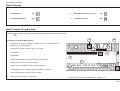
Machine Functions and Additional Functions (Menu Keys)
Operating panel with menu keys:
Machine Functions
Machine functions are basic functions of the machine. They can be changed for
the program sequence.
The machine functions can be selected by pressing one of the following pushbuttons:
Additional Functions
•
Main Menu (Function Survey)
(page K5B - 2)
•
Auxiliary Functions
(page K5D - 1)
•
Machine Parameters
(page K5E - 1)
Auxiliary Functions
Additional Functions
D
7
8
9
The running of cutting programs can be further automated by using additional
functions.
For this purpose, a multi-function key is available to the user.
i
4
5
6
1
2
3
•
Additional Functions
C 0
(page K5C - 1)
After any of the menu keys has been pressed a survey menu is opened which
offers several functions.
The corresponding subfunctions of the menu keys are selected by choosing the
respective identification number of the pictograph (symbol) and can be transferred into the currently selected program.
x
PROGRAMMABLE
Machine Parameters
A special function stored will be indicated in the Program Data display as a
pictograph (symbol) behind the cut size.
It is possible to store several additional functions into one step number.
Main Menu
(Function Survey)
K5B - 1
5.0 Automatic Operation
Machine Function: Main Menu (Function Survey)
Key "Main Menu"
Key "Main Menu" includes the following functions*:
Select language
Select measuring unit
Knife compensation
Resting time for knife at BDC
Maintenance cut counter
Service
Preset functions
Reference run/Auxiliary operation
Correction of current position
Adjust ment of display contrast
Block programming
Help
Menu " Language/Select measuring unit"
Menu "Knife":
Knife compensation
Resting time for knife at BDC
Maintenance cut counter
Menu Service:
access with code number
Menu "Block Programming"
Menu "Preset functions":
Correction of current position
Reference run
Adjustment of display contrast
* Technical alterations reserved!
K5B - 2
Menu "Help":
Explanation of
pictographs
5.0 Automatic Operation
Select Language / Measuring Unit
Select "Main Menu" (Funtion survey)
Press key
< menu appears >
Select function (LANGUAGE or MEASURING UNIT):
1.
Key input:
(language) or
(measuring unit)
2.
Select language or measuring unit: Enter number
Service
After selection display of machine identification (electronical type plate)
appears.
Possible inputs:
• Machine equipment
• BAUM safety check
• Name of inspector
You can jump to the next input line by pressing key
.
You can move to the next pages with the help of the Cursor keys.
To store your entries: press key
"Enter".
.
The additional functions of the "Service menu" are only accessible to
BAUM service or its agencies. Access only after entering a code number.
K5B - 3
5.0 Automatic Operation
Knife Compensation
Calibration to compensate for knifes of different thickness
Select menu "Knife" with key
Select function:
Select "Knife compensation":
Enter correction with keys
or
; store with
Knife change
- see chapter "6.0 Knife Change"
K5B - 4
5.0 Automatic Operation
Resting Time for Knife at BDC
Adjustment of the time knife remains in its bottom dead center (BDC).
Adjust time:
1.
Select menu "Knife" with key
2.
Select "Resting time for knife at BDC" with key
3.
Enter desired grade (1 - 9) by numerical keyboard
Abortion of menu press key
K5B - 5
5.0 Automatic Operation
Maintenance Cut Counter
Operation: Shows maintenance intervals.
Has been set to 100.000 cuts by manufacturer.
Counter starts at "0" or other preset amount and counts upward. After reaching
100.000, at every start-up, the operation display will read
OBSERVE MAINTENANCE SCHEDULE
Select maintenance cut counter
Set counter:
1.
Enter number of cuts via keyboard
2.
Press key
"Enter"
< automatic change of image back to selection image >
K5B - 6
5.0 Automatic Operation
Preset Functions
Selection of "Main Menu":
Correction of Current Position
Basic measurement = distance between backgauge rake and knife
This menu allows the inspection and correction of the basic position (actual
position) of the machine.
If the basic measurement indicated corresponds to the actual
backgauge position:
Select "Current Position OK“
.
If the basic measurement indicated does not correspond to the actual
backgauge position:
Select "Correct. current pos.":
Calculate basic position:
1.
2.
3.
4.
5.
6.
Position backgauge at any position (e.g.: 10.5 cm)
Feed paper and cut it
Place backgauge at smaller size (e.g. 10 cm)
Turn paper by 180° and cut again
Determine actual paper length of the part by sliding caliper (e.g. 10.2 cm)
Enter and store measured size.
From this display you can activate the Auxiliary Operation see also chapter "7.0 Malfunctions/Breakdowns".
K5B - 7
5.0 Automatic Operation
Continuing: Preset Functions
Select function "Preset functions":
Scan Reference Positionj
In the case of a machine malfunction the reference point can be newly
scanned with this function.
Procedure:
1.
Select "Scan reference position"
< display change >
2.
Confirm "Clear table surface"
< display change >
3.
Start backgauge run: Actuate electronical handweel in forward or
reverse operation
Abortion of reference run:
Press key
As soon as the reference run has been terminated, the menu "Correct. current
position" is displayed.
The displayed basic measurement must be confirmed (see page K5B - 7).
After this procedure the Program Data display will automatically be indicated.
Auxiliary operation
If no reference point is found during the reference run an auxiliary mode must
be activated (see page K7 - 3)
Possible funtions in Auxiliary mode:
•
•
K5B - 8
cutting
manual displacement of backgauge by means of of electronic handwheel
5.0 Automatic Operation
Adjustment of Display Contrast
In this menu image the display contrast can be adjusted in four steps.
Procedure:
Enter step number of desired contrast (1-4) via keyboard.
End of input with key
K5B - 9
5.0 Automatic Operation
Block Programming
Selection of Block Programming with key
Block Programming = automatic programming
Blcok Programming is fitted with graphic operator prompting for the automatic
generation of a cutting program for printed and unprinted sheets.
The required cutting sizes and remarks are automatically stored in a free program.
There are 3 variations of Block Programming with up to 8 available block
programming modes. The selection of a variation is done by cursor keys.
Variation 1: Size cut with edge trim entry
Consisting of:
1
2
3
Variation 2:
Size cut with final size entry without edge trim entry (with
the possibility of edge trim preadjusting)
Consisting of:
1
2
3
Variation 3:
Size cut with optimisation of final size trim with labels
without edge trim entry (with the possibility of edge trim
preadjusting)
Consisting of:
1
2
Angular cut
Four edge trim
Four edge trim with labels
Variation 1
Final size angular cut
Final size four edge trim
Final size trim with labels
Variation 2
Final size optimisation
Four-size trim with labels and trim cuts
Variation 3
K5B - 10
(with edge trim preadjusting)
5.0 Automatic Operation
Block Programming
Setting up a Block Programming
Example: Variation 1, selection: 1 Angular cut
1.
Select cutting mode
2.
Menu:
"Angular cut"
1 Orig. sheet size
2 Sheet size tables
3 Lay guide lft / ri
With this menu it is able to enter the original sheet size manually or to select a
sheet size from a sheet size table.
Angular cut
3.
Selection: Enter orig. sheet size
4.
Enter "Original sheet size X", confirm with key
5.
Enter "Original sheet size Y", confirm with key
or
6.
Selection: Sheet size tables
7.
Select left-hand lay guide (=default) or right-hand lay guide:
Example: Select right-hand lay guide by means of key
8.
Select desired sheet size by means of the cursor keys and confirm with
key
To be continued with next page!
K5B - 11
5.0 Automatic Operation
Block Programming
Confirm the sheet orientation or turn sheet orientation (observe paper grain)
Menu:
8.
1 Sheet orient. OK
2 Turn sheet
e.g.: "Sheet orient. OK"
Enter Edge trim
9.
Enter "Edge trim width X", confirm with key
10.
Enter "Edge trim width Y", confirm with key
11.
Finish entry with key
"Enter"
< Program data display appears with a graphic window of the current
Block Programming variation (visible sheet orientation with order start),
see also page K5D - 3 "Graphics OFF" >
Selection of an input parameter with Block Programming
Actuate cursor keys (browse) until desired parameter appears
Correction of an input parameter with Block Programming
1.
Select parameter with cursor keys
2.
Enter new parameter (old parameter is erased)
3.
Press key
Attention!
Function "Help":
Explanation of pictographs and
description of functions
Deletion of an input parameter with Block Programming
K5B - 12
1.
Enter Block Programming (initial fig.)
2.
Press key
"Delete"
5.0 Automatic Operation
Block Programming
Example: Variation 1, selection: Four trim cut
"Four trim cut"
1.
Select
2.
Menu:
3.
e.g.: Enter Orig. sheet size
4.
Enter Original sheet size X, confirm with key
5.
Enter Original sheet size Y, confirm with key
6.
or e.g.: Sheet size tables
7.
Select left-hand lay side (=default) or right-hand lay side:
1 Orig. sheet size
2 Sheet size tables
3 Lay guide lft / ri
With this menu it is able to enter the original sheet size manually or to select a
sheet size from a sheet size table.
Four trim cut
Example: Select right-hand lay side by means of key
8.
Select desired sheet size by means of the cursor keys and confirm with
key
Confirm the sheet orientation or turn sheet orientation (observe paper grain)
Menu:
8.
1 Sheet orient. OK
2 Turn sheet
e.g.: Sheet orient. OK
Enter Edge trim
9.
Enter "Edge trim width X", confirm with key
10.
Enter "Edge trim width Y", confirm with key
11.
Finish entry with key
"Enter"
< Program data display appears with a graphic window of the current
Block Programming variation (visible sheet orientation with order start),
see also page K5D - 3 "Graphics OFF">
K5B - 13
5.0 Automatic Operation
Block Programming
Example: Variation 3, selection :
3 Four trim cut with labels
1.
Select
"Four trim cut with labels"
2.
Menu:
1 Orig. sheet size
2 Sheet size tables
3 Lay guide lft / ri
With this menu it is able to enter the original sheet size manually or to select a
sheet size from a sheet size table.
3.
e.g.: Enter Orig. sheet size
4.
Enter Original sheet size X, confirm with key
5.
Enter Original sheet size Y, confirm with key
or
6.
e.g.: Sheet size tables
7.
Select left-hand lay side (=default) or right-hand lay side:
Example: Select right-hand lay side by means of key
8.
Select desired sheet size by means of the cursor keys and confirm with
key
Confirm the sheet orientation or turn sheet orientation (observe paper grain)
Menu:
9.
1 Sheet orientation OK
2 Turn sheet
e.g.: Sheet orientation OK:
To be continued with next page!
K5B - 14
Four trim cut
with labels
5.0 Automatic Operation
Block Programming
Enter Edge trim
10.
Enter "Edge trim width X", confirm with key
11.
Enter "Edge trim width Y", confirm with key
12.
Menu
1 Final size entry
2 Sheet size tables
13.
e.g.: "Enter final size"
14.
Enter "Final size X", confirm with key
15.
Enter "Final size Y", confirm with key
or
16.
e.g.: "Sheet size tables"
17.
Select desired sheet size by means of the cursor keys and confirm with
key
Menu
1 Label orient. OK
2 Turn material
18.
Make selection
19.
Finish entry with key
"Enter"
< Program data display appears with a graphic window of the current
Block Programming variation (visible sheet orientation with order start),
see also page K5D - 3 "Graphics OFF"
K5B - 15
5.0 Automatic Operation
Block Programming
Example: Concerning variant 3, selection:
1.
Select
2.
Selection menu:
2 four-side trim with labels
and trim cuts
"four-side trim with labels and trim cuts"
1 initial sheet size
2 Table of sizes
3 Lay guide lft / ri
In this menu, a selection can be made between:
- the manual input of the initial sheet size and label size
- the selection of an initial sheet size and label size from a table of sizes
with trimouts upon label cutting.
3.
Example: "Enter initial sheet size":
4.
Enter initial sheet size "X" confitm with button
5.
Enter initial sheet size "Y" confirm with button
or
6.
Example: "Table of size":
Select desired size with cursor keys and confirm with button
(format measurements are transferred block program)
7.
Select left-hand lay side (=default) or right-hand lay side:
Example: Select right-hand lay side by means of key
Confirm or change the sheet position (observe feeding direction of paper)
Selection menu:
8.
1 Sheet positionOK
2 Turn the sheet
Example: "Sheet position OK":
To be continued with next page!
K5B - 16
four-side trim with
labels and trim cuts
right-hand
lay side
5.0 Automatic Operation
Block Programming
Enter outside trim
9.
Enter outside trim "X" confirm with button
10.
Enter outside trim "Y" confirm with button
11.
Selection menu:
12.
Example: "Input of final size":
13.
Enter final sheet size "X" confirm with button
14.
Enter final sheet size "Y" confirm with button
1 Input of final size
2 Format tables
or
15.
Example: "Table of sizes":
16.
Select desired format via cursor keys and press key
(format
measurements are transferred into block program)
Selection menu:
17.
1 label position OK
2 Turn label
Example: "Label position OK":
Enter trimout measurement
18.
Enter trimout measurement "X" confirm with button
19.
Enter trimout measurement "Y" confirm with button
To be continued with next page!
K5B - 17
5.0 Automatic Operation
Block Programming
20.
Enter label sequence "X" confirm with button
21.
Enter label sequence "Y" confirm with button
Explanation:
X: 1 / 1 = 1 Label + 1 trimout in X-direction
Y: 2 / 1 = 2 Labels + 1 trimout in Y-direction
22.
Selection menu:
1 Finish input
2 Select cutting sequence
23.
Example: "Sel (ect) cutting sequence":
24.
Select desired cutting sequence, such as e. g. "cutting sequence
crosswise:
25.
Close input with "Enter" key
< Program Data Image is displayed with graphic display of block
program variant 1, 2, or 3 (= visual position of sheet upon start of job),
please refer to page K5D - 3 "disconnect graphics" >
K5B - 18
5.0 Automatic Operation
Menu Key: Additional Functions
Key "Additional Functions"
Jogging mark
Key "Additional Functions" includes the following operations*:
Jogging mark
Ejector OFF
Help
The running of cutting programs can be further automated by using Additional
Functions.
The Additional Function can be selected on the operating panel under menu key
"Additional Functions"
It is possible to store several Additional Functions into one step number.
Ejector OFF
Help
Explanation of
pictographs
* Technical alterations reserved!
K5C - 1
5.0 Automatic Operation
Storage of Additional Functions with Cut Size
1.
Enter cut size
2.
Press key
3.
Enter number of desired Additional Function
4.
Press key
< additional function menu is opened >
< for identifying the stored Additional Function the symbol is
displayed behind the step number >
Subsequent Storing of Additional Functions
1.
Select program
< program data display appears >
2.
Select step number
3.
Press key
"Correction"
4.
Press key
< add. function menu is displayed >
5.
Enter number of desired Additional Function
Additional functions:
Jogging mark
< symbol is displayed in input section >
6.
Press key
"Enter"
< additional function is stored; symbol is displayed behind the step
number >
Erase Additional Function:
Repeat above procedure
K5C - 2
Ejector OFF
5.0 Automatic Operation
List of Additional Functions
Additional function:
Jogging mark
Ejector OFF
Operation:
Knife block:
A stored jogging mark for exact line up against backgauge and side guides will
block the cut at this position. When pressing the cut buttons a beep sounds and
operation mode shows "Jogging mark"
Prior to backgauge reverse no automatic ejector
K5C - 3
K5C - 4
5.0 Automatic Operation
Menu Key: Auxiliary Functions
Key "Auxiliary Functions"
Key "Auxiliary Functions" includes the following functions*:
Cut and record
Sheet size tables
Cut and record
Sheet size tables
Graphics OFF
Subtraction repetition unit
Help
Graphics OFF
(in Program
Data display)
Subtraction
repetition unit
Help
Explanation of
pictographs
* Technical alterations reserved!
K5D - 1
5.0 Automatic Operation
Cut and Record
1.
Select free program
2.
Press key
3.
Select
"Cut and record"
4.
Make cut
< actual size is stored upon every cut >
"Auxiliary Functions"
After program generation:
Switch function off by selecting it again (when program is changed or "Automatic
On" is activated function is switched off automatically!)
Sheet Size Tables
List of DIN sizes A0 - A9.
The corresponding sizes (lengths or widths) can be selected by cursor and
transferred to the input section.
Procedure:
1.
Press key
2.
Select desired size (length or width) using cursor keys
3.
Press key
< Value is transferred to the input section >
K5D - 2
5.0 Automatic Operation
Subtraction Repetition Unit
Fast and easy programming of a sequence of equal cut sizes.
Procedure:
1.
Move backgauge to desired initial position
2.
Select "Auxiliary Functions" with key
3.
Select
4.
Enter label size (e.g.: 2 cm)
5.
Make cut
"Subtraction Repetition Unit"
activated function
After each cut backgauge moves forward 2cm until backgauge reaches the front
limit position.
Note:
The label size can be changed during this process.
After backgauge has reached the front limit position, backgauge moves back to
the initial position.
Quitt the function
Quitt the function by selecting the function once more or by pressing key
"Automatic ON"
Graphics OFF
Switching OFF the graphic window
Data display.
of a Block Program shown in the Program
K5D - 3
K5D - 4
5.0 Automatic Operation
Menu Key: Machine Parameters
Key "Machine Parameters"
Key "Machine Parameters" includes the following functions*:
Prepressure time
Resting time for knife at BDC (bottom dead center)
* Technical alterations reserved!
K5E - 1
5.0 Automatic Operation
Prepressure Time
With spongy or soft stock it is recommended to increase the clamping time
before the actual cut.
The adjusted pre-pressing time is the period between start of clamping and
initiation of cut. For this purpose, 9 pre-clamping grades are available.
Make selection:
Select prepressing time:
< selection display is shown >
Adjustment of pre-pressure time:
Select desired prepressing time grade by entering the clamping grade
number
< after seletion the Program Data display appears >
_________________________________________________________________
Resting time for knife at BDC
By means of this function the time period "knife in bottom dead center (BDC)"
can be adjusted.
Adjustment of BDC time
Select desired time grade by entering the time grade number (1 - 9) with
the numerical keyboard
< after selection the Program Data display appears >
K5E - 2
6.0
Knife Change
Knife change may only be carried out by especially authorized employees!
K6 - 1
6.0 Knife Change
Knife change
The knife change should only be carried out by specially trained
personnel
Tools required:
1 Knife wrench
1 Knife guard
2 Knife holders
D
7
i
4
1
8
9
5
6
2
3
x
C 0
PROGRAMMABLE
Removing the knife
1.
Select display "Main menu" (Function survey) with key
.
i
Make selection "3 Knife".
Select "2 Knife change"
2.
Bring turning knob (i), located beneath the front table, to position "Knife
change"
3.
Press both cut buttons and keep them pressed until knife bar stops
automatically at the lower position
4.
Remove knife screw at the very left-hand side; turn knob (i) to "0 position" < knife bars moves upward >
5.
Loosen both knife screws (a) at the two knife bar slots (b).
Screw both handles of the knife guard (c) into the now accessible bolt
holes
6.
Remove the remaining knife screws (knife is fixed to the knife bar by the
two handles)
7.
Pull knife guard forward by means of the two handles (de-activate
clamping) and pull the knife downward, out of the knife bar.
8.
Deposit knife in knife box!!
Remove knife guard*
*
K6 - 2
HANDLE THE KNIFE WITH UTMOST CARE!
WHEN TRANSPORTING THE KNIFE WITHOUT
KNIFE BOX, USE ALWAYS THE KNIFE GUARD.
position
"knife change"
"0-position"
6.0 Knife Change
Knife Change
Mounting the knife
1.
Replace cutting stick or turn same over (see page K6 - 5)
2.
Turn adjusting cam (e) to the "0 - position" by means of the knife
wrench
3.
Screw knife handles (c1) into the black bordered bolt holes (f) of the new
knife
g
4.
Take knife out of the knife box
b
5.
Remove knife handles (c1) and mount knife guard (c)
6.
Insert the knife into the knife bar slots (b) and lift it up into the elongated
holes (g; Attention! Mind the clamping resistance of the knife guard)
7.
Release knife guard (knife is clamped to knife bar)
8.
Screw all knife screws (except screw at the very right-hand side!) slightly
into the lower bolt holes*; do not fasten them!
9.
Remove knife guard
10.
Slightly screw-in the remaining screws, but do not fasten them!
11.
Push the knife at the center screw (h) up to its topmost position by means
of the knife wrench and fasten it
e
f
d
Continuation next page
h
* See also "Knife Adjustment", page K6 - 4, item 3
K6 - 3
6.0 Knife Change
Knife Change
Knife adjustment
D
7
i
4
1
8
9
5
6
2
3
x
C 0
PROGRAMMABLE
1.
Bring turning knob (i), located beneath the front table, to position "Knife
change".
2.
Press both cut buttons and keep them pressed until knife bar stops
automatically at the lower position.
3.
Loosen center knife bolt (knife should now drop down to the cutting
stick. If necessary use the knife wrench to push down the knife against the
cutting stick).
Attention!
In case the knife does not reach the cutting stick:
Screw the knife bolts in the upper bore-holes of the knife.
4.
Screw-in knife screw at the very left-hand side.
5.
Tighten up all knife bolts!
6.
Bring turning knob (i) back to "0 - position" (knife bar should return automatically to upper resting position).
7.
Insert knife screw at the very right-hand side and tighten it.
8.
Move adjusting can (e) to position 1.
9.
Finish knife change by pressing key 1.
i
position
"Knife change"
"0 - position"
Adjustment of knife pre-tension
If hard material is to be cut (such as cardboard) it may be necessary to increase
the pre-tension of the knife if the bottom sheet has not been cut through.
Adjusting the knife:
Tool needed: Knife wrench.
Move adjusting cam (e) on the knife bar to position 1 - 3* .
* required position depending on the material to be cut should be found by test
cuts.
K6 - 4
e
6.0 Knife Change
Changing of cutting stick
The BAUM sinus cutting stick is made of high resistance plastic material.
Due to the unusual wavy design a tight fitting in the table grove is assured
without the need for glue or screw.
Each cutting stick is useable 4 times as they are turned around.
Removing of cutting stick
Tool needed: normal screw driver
1.
Lift cutting stick slightly on the left side cutting stick stop
2.
Prey out cutting stick carefully from left toward the right.
Clean cutting stick table grove!
normal
turn over
replace
Inserting of cutting stick
1.
Rest cutting stick end against the right stop and work into the grove
2.
Follow the wavy form of the cutting stick when pressing into the table
grove. Press down hard to assure total seating of stick.
K6 - 5
K6 - 6
7.0
Malfunctions / Breakdowns
K7 - 1
7.0 Malfunctions/Breakdowns
Electrical Malfunctions/Breakdowns
Electrical malfunctions of the machine will appear in the status display in plain
text and with an error number.
The operator is warned by a beep sound.
In that case, the operator has to decide whether it is an
•
•
•
operation error,
programming error,
malfunction of the machine.
Remedy for operating error (programming error):
•
•
check program data or input, resp.
correct any mistakes
Remedy for machine malfunctions:
•
turn machine off and on again
if error message has disappeared:
•
resumen function
if error message appears again:
•
K7 - 2
call service technician, indicate the error message
7.0 Malfunctions/Breakdowns
Start - Up Breakdown: Scan Reference Point/Auxiliary Mode
Malfunction:
After machine has been started, display shows
after turning off the machine:
"SCAN REFERENCE POINT"
Cause:
Machine was shut off during backgauge movement
Remedy:
Scan reference point
1.
Select "(1) Reference position scan"
< prompt appears: clear the table >
2.
Select "(1) Confirm when table empty"
< prompt appears: go to reference position >
3.
Activate electronic handwheel
< backgauge moves to reference point >
Reference run can be interrupted by pressing key
If reference point is found:
< menu display "Correction of basic position" >
4.
Check basic position and confirm (see page K5B - 7)
< program data display appears >
Auxiliary mode
if reference point scanning fails:
If the reference point scanning fails:
1.
Turn machine off and on again < menu "Scan reference position"
appears >
2.
Select "Auxiliary Mode"
3.
Select machine type; confirm with
Machine functions possible in Auxiliary Mode:
•
cutting
•
backgauge movement with handwheel or backgauge movement keys
K7 - 3
7.0 Malfunctions/Breakdowns
Mechanical Breakdown: Rupture of a Knife Bar / Clamp Recuperating Spring
Breakdown:
Knife bar stops beneath the upper dead centre
Cause:
Rupture of a knife bar recuperating spring
Remedy:
Switch machine off immediately and call the service
technician! Do not access the machine! Guard the knife
zone against manual access by operator!
Type of malfunction:
When one of the two recuperating springs of the knife bar has broken the knife
bar is lifted by the second spring, but stops shortly beneath the top dead centre
(OT). No more cuts can be triggered. Malfunction display: Knife not in top dead
centre!
Attention!
The machine is in a dangerous condition, because the cutting edge of the knife
is no longer completely covered by the clamp.
Any access to the machine may cause severe injury at that time.
Breakdown:
Clamp stops beneath the upper dead centre
Cause:
Rupture of a clamp recuperating spring
Remedy:
Switch machine off immediately and call the service
technician. Do not access the machine! Guard the clamp
zone against any manual access by operator!
Type of malfunction:
When one of the two recuperating springs of the clamp has broken the clamp is
lifted by the second spring, but stops shortly beneath the top dead centre.
Backgauge movement is locked. No more operations can be performed! When
the electronic hand wheel is actuated the following message is displayed: Clamp
not in top dead centre!
K7 - 4
Example for protecting the machine in the case of
a rupture of a knife bar / clamp recuperating spring:
Message displayed:
Knife bar or clamp not in top dead centre!
D
7
8
9
i
4
5
6
1
2
3
x
C 0
PROGRAMMABLE
Attention!
Do not access machine.
Risk of injury!
8.0
Maintenance
Prior to any maintenance work, cut off machine and
disconnect power supply.
Caution!
All the cables marked with the symbol
are still alive
(mains voltage) even if the main switch is shut off.
K8 - 1
Basic information about servicing and maintenance work
•
Always turn off the machine and disconnect the power supply before
undertaking any maintenance work.
•
In the event of defective safety equipment, e.g. safety light barriers,
protective covers, etc., the machine/system must be taken out of
operation and repaired immediately.
•
All safety signs on the machine/system must be in impeccable and
easily identifiable condition. Replace safety signs if this is not the
case.
•
Proceed as follows if maintenance work necessitates stepping onto
individual system components, e.g. lubrication of gripper
components on the
cutting machine rear table or conveyor lines:
Warning!
All cables designated
, and all cables with orange cladding will
remain live even after turning off at the main switch!
•
Once the plant is turned off, prevent it from being turned back on
again by blocking the relevant main switch. If necessary, warning
signs should also be put up at the main switches to alert others to
maintenance work in progress.
•
Due to the need for special tools, we recommend that maintenance
and lubrication work be carried out by the POLAR After-Sales Service.
•
The product recommendations contained in these operating
instructions, e.g. for oils and greases, may be regarded as up-to-date
at the time of going to press.
We cannot guarantee either the correctness or completeness of
these instructions. The user is responsible for ensuring compliance
with all the applicable laws and regulations before using these
products. To ensure this, the relevant technical and safety data
sheets should be obtained from the appropriate manufacturers
before use. The user is advised to meet his obligations in respect of
product observation, and to exercise due care when using the
products.
Polar will not be held responsible for any kind of damage or injury
due to failure to comply with the descriptions provided by the
various manufacturers, or due to the risks associated with the nature
of the product
•
K8 - 2
Compliance must be assured with the legislation on electrical plants
or systems, hydraulic and/or pneumatic equipment as applicable in
the country of use.
Before stepping onto conveyor units, pallets or cutting machine rear
table:
Cover surfaces to be stepped on with cardboard and secure
cardboard in place with adhesive tape.
Warning! Slippery underfooting: Risk of slipping!
After finishing the works:
Totally remove cardboard and adhesive tape as well as any remains
of adhesive tape from the surfaces.
•
For lubrication dismantle any guards at the guide units. Assemble
the guards immediately after the maintenance work has been
performed (Safety!).
•
After lubrication:
Use a rag to remove any excessive lubricant (greases, oils)
completely which seeps out, especially above the table surfaces that
contact the material to be cut.
•
The specified maintenance intervals are based on an operating time
of 8 hours / day. For multi-shift operation the maintanance intervals
need to be adapted correspondingly.
HYDRAULIC
We recommend to have oil changed and unit checked by
BAUM and/or authorized personnel.
Attention when bleeding hot oil - danger of burning!
Oil change:
approx. every 6000 hrs.
Fill in oil up to middle of oil level indicator!
Quantity (liters): 22,5
BACKGAUGE DRIVE (grease lubrication)
Lubrication by grease gun!
1.
2.
3.
Move backgauge to position 42 cm (16,5 inches)!
Remove lid (C) at backgauge drive guard
Grease spindle via lubricating nipple
2 - 3 strokes with the grease gun are sufficient.
Lubrication intervals: monthly
GUIDINGS FOR KNIFE AND CLAMP (grease lubrication)
Lubrication by grease gun!
1.
2.
Lubricate guidings for knife bar (A) from the front side:
2 lubricating nipples at the front plate
Lubricate clamp guidings from the rear side (B):
2 lubricating nipples
Usable oil brands (DIN 51524, in alphabetical order):
ARAL Vitam GF 46
AGIP Oso 46
BP Energol HLP-HM 46
CASTROL Hyspin SP 46
DEA Astron HLP 46
ESSO Nuto H 46
ELF Elfolna 46
FINA Hydran AF 46
FUCHS Renolin B, rot
KLÜBER Lamora HLP 46
MOBIL DTE 25
OPTIMOL Hydo 46 or Hydo MV 32
SHELL Tellus C 46
TOTAL Azolla ZS 467
Usable grease brands (DIN 51825, in alphabetical order):
ARAL Radlagerfett
AGIP Autol Top 2000 or
Longtime Grease 2
BP Energrease LS 2
DEA Paragon EP 2
ESSO Unirex N2 or Essonorva 275
FINA Pluton AX 2
KLÜBER Centoplex 2 EP
MOBIL Mobilgrease XHP 222
OPTIMOL Longtime PD 2
SHELL Retinax LX 2
TOTAL Multis EP 2
D
i
7
4
1
8
9
5
6
2
3
x
C 0
PROGRAMMABLE
A
B
C
2 - 3 strokes with the grease gun are sufficient.
Lubrication intervals: weekly
K8 - 3
BATTERIES FOR DATA STORAGE
To be replaced only by BAUM service or agencies.
Batteries inside machine are used for data storage.
Replacing after approx. 5 years
CLEANING OF DISPLAY
1.
2.
Turn off machine
Use glass cleaner and soft lint-free rag.
MAINTENANCE INTERVALS
Maintenance should only be carried out by BAUM Service exclusively!
5 hrs. per day equal:
Please call for maintenance or service ahead of due date!
The address of the representation can be read from the plate on the machine.
6.000
K8 - 4
= 5 years (hydraulics/batteries for data storage)
For these documents we reserve all legal rights. They are not to be copied
or made known to others, without express agreement, regardless of what
form they might take. Violations will entail liability for damages.
K8 - 5
Service:______________________________________________
_____________________________________________________
Mr./Mrs.: _____________________________________________
BAUM USA
1660 Campbell Road • Sidney, Ohio 45365
Phone 937/492-128 or 800/543-6107
Fax 937/492-7280
© 1999 BAUM USA
Printed in USA
Technical alterations reserved
11/76/PD/76D1133 (V1.2.0)