1
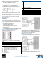
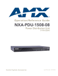
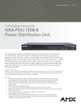
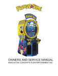
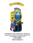
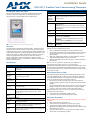
Installation Guide
ENV-VST-C ViewStat Color Communicating Thermostat
ATTENTION: READ THIS FIRST!
ViewStat Color Communicating Thermostat Specifications (Cont.)
For more detailed installation, configuration, programming, and operating
instructions, refer to the ViewStat Color Communicating Thermostat
Operation/Reference Guide available on-line at www.amx.com.
Circuit Board Components:
Communication Terminals with captive-wire connectors that connects to the
and HVAC
thermostat, HVAC equipment, control system, remote sensors,
Equipment
and power supply.
connectors
Enclosure:
FIG. 1 ENV-VST-C ViewStat Color Communicating Thermostat
Material
White plastic and removable front panel. Panel can be painted to
match wall decor.
Warning: If you paint the panel, do not paint over the exposed
thermistor. Doing so can cause the external temperature sensor to
work improperly.
Dimensions
(HWD)
5.31" x 3.93" x 1.18" (13.48 cm x 9.98 cm x 2.99 cm)
Weight
5.29 oz. (150 grams)
Included
Accessories
ENV-VST-C ViewStat Color Communicating Thermostat
Installation Guide (93-2050-01)
ENV-VST-TSO ViewStat Indoor/Outdoor Temperature sensor
(FG2050-22)
i!-Weather application (FG3005-20), three-year subscription
Optional
Accessories:
ENV-VST-TSF ViewStat Indoor Flush Mount Temperature Sensor
(FG2050-21)
Overview
Installing a Remote Sensor
The ViewStat Color Communicating Thermostat (FIG. 1) provides the current
temperature (from an on-board sensor, a remote sensor, or an average of the
on-board and remote sensors), controls and displays humidity, and displays the
current outdoor temperature. The thermostat displays this information on a 3.5"
(8.89 cm) color display. In addition, the thermostat provides the current day's
weather forecast along with a five-day forecast, when connected to an
Internet-enabled Master. The forecast information is driven from AMX’s
i!-Weather application. A three-year subsciption to i!-Weather is included with
purchase of the thermostat.
Follow these steps to install the remote sensor:
Specifications
ViewStat Color Communicating Thermostat Specifications
Control Voltage
24 VAC (interfaces with a power supply through the RC terminals.)
Warning: Exceeding the control voltage may cause damage to
the thermostat.
Switched
Voltage
18 – 30 VAC, 57-63 Hz
Maximum
Operating
Current
2 amps total at rated voltage, through all outputs.
1 amps through any one output.
Maximum
Surge Current
2.0 A
Internal Battery
CR2032 for maintaining real-time clock settings during a power
loss.
Control
Accuracy
±1.0° F (± 0.56° C)
±3% relative humidity
Temperature
Range
Maximum displayable indoor temperature: 40° – 99° F
(5° – 37° C)
Maximum displayable outdoor temperature: -40° – 120° F
(-40° – 49° C)
Operating
Range
32° – 122° F (0° – 50° C)
1.
2.
3.
4.
Drill a 1/4" hole into the drywall where you want to install the sensor.
Fish the cable that connects to the sensor through the 1/4" hole in the wall
until the edge of the sensor, where the cord meets the sensor, is flush
against the wall.
Apply caulk, drywall putty, insulation, or any other appropriate sealant to
the hole in the wall around the sensor to seal the hole.
Attach the connecting wires from the sensor to the S1 and S2 terminals on
the thermostat.
Note: You can use a maximum of 300 ft (91.44 m) of 18 AWG wire for
connecting the indoor/outdoor remote sensor to the thermostat.
The thermostat automatically defaults to using the on-board temperature sensor
when you install it. For information about activating the remote sensor, consult
the Activating the External Sensor section of the ViewStat Color Communciating
Thermostat User Guide.
Mounting the Base to a Wall
You should only mount the thermostat onto a sheetrock wall with the anchors
and screws provided with the unit. There are four screw holes located on the
base of the thermostat. No tools are required to disassemble the thermostat—
simply use your hands to pull the front panel off of the base.
1.
2.
Place the base over the wire hole opening in the wall. Level the base
(leveling required for appearance only) and mark the screw hole mounting
locations.
Using the supplied wall anchors, drill 1/4" hole in the center of the marked
locations, and tap the wall anchors into the holes. If using the supplied
screws only, drill a 3/32" hole in the center of the marked locations.
Note: Minimize the wire entry hole size and seal. Drafts from inside the wall
could affect temperature readings.
3.
4.
Fasten the base to the wall with the supplied screws.
Seal the wire entry with caulk, drywall putty, or insulation.
Front Panel Components:
Wiring the Thermostat
Main LCD
display
3.5" (8.89 cm) color QVGA (320 x 240) Thin Film Transistor Liquid
Crystal Display (TFT-LCD).
Note: A qualified HVAC technician should perform these steps to ensure proper
termination.
Navigation
buttons
The Navigation buttons are used to change various parameters on
the thermostat, including the temperature setpoints. These
buttons are located beneath the display.
1.
2.
3.
Mode/Select
button
The Mode/Select button is used to navigate through the various
thermostat screens, including the weather screens. This button is
located beneath the display.
4.
Make sure the HVAC system power is off.
Strip 1/4" (0.63 cm) of insulation from each wire you are using.
Secure the wires into the terminals on the base according to the
appropriate wiring diagram. Use color-coding practices (i.e. white wire to W
terminal) whenever possible.
Check each wire to ensure it is securely fastened, not broken, and any
exposed wires are not touching each other.
Wiring for AxLink
Follow these steps to connect the wiring into a captive-wire connector:
1.
2.
3.
Strip 1/4 inch off the wire insulation for all four wires.
Tin 2/3 of the exposed wire.
Insert each wire into the appropriate captive-wire connector up to the
insulation.
Tighten the captive screws to secure the fit in the connector.
4.
Use 18 AWG wire to connect the AxLink wiring from the thermostat to the
connector on the AxLink device as shown in FIG. 2.
FIG. 2 AxLink wiring
Note: The ViewStat Color Communicating Thermostat interfaces with a 24
VAC power supply from the heating/cooling unit through its RC terminal. You
should not connect the power wiring from the AxLink device to the thermostat
with the intent of using the AxLink device to provide power to the thermostat.
The L1 terminal on the thermostat can accept the AxLink +12VDC wire and you
can connect the wire to the terminal if you want to assure there are no loose
wires inside the thermostat, but you should not power the thermostat by
running a jumper to the RC pin.
Communication and Equipment Terminal Wiring Definitions (Cont.)
Y2
2nd stage compressor
B
Reversing valve (heat)
O
Reversing valve (cool)
DEH
Dehumidify
HUM
Humidify
S1
External thermistor. The ViewStat Color Communicating Thermostat
supports only one external sensor.
S2
External thermistor. The ViewStat Color Communicating Thermostat
supports only one external sensor.
L1
AxLink PWR
L2
AxLink AxP
L3
AxLink AxM
L4
AxLink GND
Single Stage Furnace and Single Stage A/C
FIG. 4 displays the thermostat wiring for a system with a single stage furnace
and A/C.
Wiring Diagrams
ViewStat Color Communicating Thermostats are equipped with terminals RC,
RH, C, Y, W, G, O, B, S1, S2, L1, L2, L3, and L4. You can use terminals S1 and
S2 to accomodate a remote temperature sensor. Terminals L1-L4 connect to
the AxLink cable. The remaining terminals are used to control various types of
heating and cooling systems. You can use the thermostat with the following
types of heating and cooling systems:
•
•
•
•
•
•
Single Stage Furnace and Single Stage A/C
Dual Stage Furnace and Dual Stage A/C
Roof Top Unit with Dual Stage Heat and Dual Stage Cool
Boiler with A/C with Separate Transformers
Single Stage Heat Pump
Two Stage Heat Pump
•
First Stage Radiant Floor Heat, Second Stage Furnace One Stage of
Cooling
Communication and Equipment Terminal Wiring Definitions
FIG. 4 Single Stage Furnace and Single Stage A/C wiring
FIG. 3 displays the terminal layout for the thermostat.
The thermostat automatically defaults to One Stage Furnace for the HVAC
System setting when you install it. For information about changing the HVAC
System setting, consult the Changing the Type of HVAC System section in the
ViewStat Color Communciating Thermostat User Guide.
Dual Stage Furnace and Dual Stage A/C
FIG. 5 displays the thermostat wiring for a system with a dual stage furnace
and A/C.
FIG. 3 Terminal Layout
The following table lists the communication and equipment terminal wiring
definitions:
Communication and Equipment Terminal Wiring Definitions
RH
24 VAC in
RC
24 VAC in for AC relays. If a separate 24 VAC is not supplied to the RC
terminal, you should install a jumper from RH to RC.
C
24 VAC common
G1
Fan on 1. If you are using a single speed fan, you should connect it to the
G1 terminal. On a multi-speed fan, G1 is the lowest speed.
G2
Fan on 2. On a multi-speed fan, G2 is the medium speed.
G3
Fan on 3. On a multi-speed fan, G3 is the highest speed.
W1
1st stage heat
FIG. 5 Dual Stage Furnace and Dual Stage A/C wiring
W2
2nd stage heat
For wiring diagrams of other types of heating and cooling systems, consult the
ViewStat Color Communicating Thermostat Operation/Reference Guide.
Y1
1st stage compressor
For full warranty information, refer to the AMX Instruction Manual(s) associated with your Product(s).
10/08
©2008 AMX. All rights reserved. AMX and the AMX logo are registered trademarks of AMX.
AMX reserves the right to alter specifications without notice at any time.
3000 RESEARCH DRIVE, RICHARDSON, TX 75082 • 800.222.0193 • fax 469.624.7153 • technical support 800.932.6993 • www.amx.com
93-2050-01
REV: C