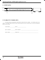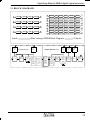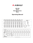
1
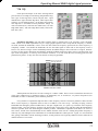
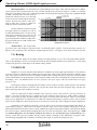
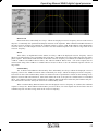
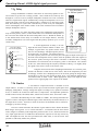
4048A
digital signal processor
&
Altec Lansing Pr
ofessional
Professional
1000 W. Wilshire Blvd. Suite 362
Oklahoma City, OK 73116 USA
A division of Altec Lansing Technologies Inc, Milford PA 18337-0277
Made In USA
Operating Manual -4048A digital signal processor
Table Of Contents
1
INTRODUCTION . . . . . . . . . . . . . . . . . . . . . . . . . . . . . . . . . . . . . . . . . . . . . . . . . . 4
2
UNP
ACKING . . . . . . . . . . . . . . . . . . . . . . . . . . . . . . . . . . . . . . . . . . . . . . . . . . . . . . 4
PA
3
AC POWER REQUIREMENTS . . . . . . . . . . . . . . . . . . . . . . . . . . . . . . . . . . . . . . 4
4
FRONT P
ANEL FEA
TURES . . . . . . . . . . . . . . . . . . . . . . . . . . . . . . . . . . . . . . . . 5
PA
AT
5
REAR P
ANEL FEA
TURES . . . . . . . . . . . . . . . . . . . . . . . . . . . . . . . . . . . . . . . . . . 6
PA
AT
6
ARE . . . . . . . . . . . . . . . . . . . . . . . . 8
A LLTEC
TEC LANSING MAESTRO ™ SOFTW
SOFTWA
7
GETTING ST
AR
TED . . . . . . . . . . . . . . . . . . . . . . . . . . . . . . . . . . . . . . . . . . . . . . . 9
STA
RT
8
OTHER SOFTW
ARE FUNCTIONS . . . . . . . . . . . . . . . . . . . . . . . . . . . . . . . . . . . 15
SOFTWARE
9
TROUBLESHOOTING TIPS . . . . . . . . . . . . . . . . . . . . . . . . . . . . . . . . . . . . . . . . 16
1 0 SPECIFICA
T I O N S . . . . . . . . . . . . . . . . . . . . . . . . . . . . . . . . . . . . . . . . . . . . . . . . 17
AT
1 1 D I M E N S I O N S . . . . . . . . . . . . . . . . . . . . . . . . . . . . . . . . . . . . . . . . . . . . . . . . . . . 18
1 2 WARRANTY INFORMA
TION . . . . . . . . . . . . . . . . . . . . . . . . . . . . . . . . . . . . . 18
INFORMATION
1 3 B L O C K D I A G R A M S . . . . . . . . . . . . . . . . . . . . . . . . . . . . . . . . . . . . . . . . . 19
2
Operating Manual-4048A digital signal processor
The lightning flash with arrowhead
symbol, within an equilateral triangle, is intended to alert the user
to the presence of uninsulated
"dangerous voltage" within the
product's enclosure that may be of
sufficient magnitude to constitute
a risk of electric shock to persons.
CAUTION
RISK OF ELECTRIC SHOCK
DO NOT OPEN
TO REDUCE THE RISK OF ELECTRIC SHOCK, DO NOT REMOVE
COVER. NO USER SERVICEABLE PARTS INSIDE. REFER SERVICING TO QUALIFIED SERVICE PERSONNEL.
The exclamation point within an
eqilateral triangle is intended to
alert the user to the presence of
important operating and maintenance instructions in the literature
accompanying the device.
TO REDUCE THE RISK OF FIRE OR ELECTRICAL SHOCK,
DO NOT EXPOSE THIS APPlIANCE TO RAIN OR MOISTURE.
TO REDUCE THE RISK OF FIRE, REPLACE ONLY WITH SAME
TYPE FUSE. REFER REPLACEMENT TO QUALIFIED SERVICE
PERSONNEL.
WARNING:
THIS APPARATUS MUST BE EARTHED
3
Operating Manual -4048A digital signal processor
&
1. INTRODUCTION
Your new 4048A is a flexible four input/eight output digital signal processor capable of precise control of a
broad range of audio functions. Because it has no user controls, it is ideal for applications where real-time changes are
unlikely or when tamper-proof security is required. All adjustments are made using Altec Lansing Maestro™ software for Windows™.
The 4048A utilizes state of the art DSP technologies, beginning with 24 bit, 48kHz delta-sigma A/D converters with 128x oversampling. Audio processing includes Gain, Parametric EQ, Signal Routing, Crossover Functions,
Time Delay, Compressor/Limiter, and Polarity Invert, all taking place in twin high performance Motorola DSP processors. D/A conversion uses 24 bit delta-sigma converters with 128x oversampling. All input and output connections are
precision balanced and RF protected using "Euro-Block" style two piece terminal block connectors.
2. UNPACKING
As a part of our system of quality control, every Altec Lansing product is carefully inspected before leaving
the factory to ensure flawless appearance. After unpacking, please inspect for any physical damage. Save the shipping
carton and all packing materials, as they were carefully designed to minimize the possibility of transportation damage
should the unit again require packing and shipping. In the event that damage has occurred, immediately notify your
dealer so that a written claim to cover the damages can be initiated. The right to any claim against a public carrier can
be forfeited if the carrier is not notified promptly and if the shipping carton and packing materials are not available for
inspection by the carrier. Save all packing materials until the claim has been settled.
3. AC POWER REQUIREMENTS
Note: The AC power switch for model 4048A is on the back panel. The Altec Lansing 4048A uses a
universal input power supply which will accept any line voltage in the range of 80VAC to 260VAC, 50-60Hz, and is
exceptionally resistant to voltage dips, or "brown outs". A standard IEC-320 grounded AC inlet is provided on the rear
panel to accept the detachable power cord. Never remove the AC earth ground connection to the 4048A. In the
event of an internal fuse failure, refer the product to a qualified service technician for fuse replacement, replacing only
with the same type and rating fuse, 0.5A time delay Littlefuse 218.500 or equivalent.
4
Operating Manual-4048A digital signal processor
4. FRONT PANEL FEATURES
4.1 Input Channels
The 4048A has four input channels, each of which can be routed to any combination of output channels. Each
input channel's three color Sig LED indicates input signal level of -20dB (green), 0dB (amber), and +20dB clip (red)
respectively. Note that the Sig LEDs detect actual signal at the input connections, before any gain adjustments are
made within the 4048A. The red input mute LED becomes lit when an input channel is turned off through software
control.
4.2 Output Channels
The eight output channels on the 4048A have three color LEDs to indicate signal, limiter threshold, and clip.
The green signal LED indicates -20dB output level. The amber limiter threshold LED depends on settings established
within Altec Lansing Software, and, assuming the limiter is active, indicates that sufficient signal level has been
reached for the limiter to begin the process of gain reduction. Clipping occurs at +20dB and is indicated by a red LED.
The red output mute LED becomes lit when an output channel is turned off through software control.
4.3 Preset Indicator
This display indicates the currently selected preset number (1-18) for the 4048A. This display also indicates
the following operating conditions within the 4048A:
- Firmware revision number is displayed during power up, and when a factory reset is aborted.
- Factory reset countdown, which occurs by pressing and holding the factory reset switch during power up.
- Contact closure event confirmation is indicated by an upper case "C" for a few seconds, followed by the active
contact/preset number (1-8).
- RS-232 bulk preset dump completion is indicated by a lower case "d". If the 4048A receives a corrupt RS-232
dump, an upper case "E" is shown.
4.4 Factory Reset Switch
This is a recessed switch in the small hole below the preset display. This recessed switch is used to perform a
factory reset by pressing and holding during power up. Note that a factory reset will erase all user defined presets
stored in the 4048A, including the user password.
4.5 RS-232 Dataport
The 4048A has two parallel RS-232 dataports, one on the front panel and one on the back, for connecting to a
computer for software control. See section 6.3 for details on connecting to a computer.
5
Operating Manual -4048A digital signal processor
5. REAR PANEL FEATURES
5.1 Input Connections
Balanced input signals are connected to the 4048A using the
included "Euro Block" connector. A flat blade screwdriver is required
to connect a stripped wire lead to the loose connector, which is then
inserted into the rear panel Euroblock receptacle. It is important that
both (+) and (-) inputs are properly terminated or signal loss and noise
may result. In other words, if an unbalanced input signal is used, connect the signal to the (+) input, and connect the ground wire to both the
(-) and ground connection.
+ -
G
Euroblock
Connector
System
+-
G
A Note About Input Signal Levels:
There are no input trim adjustments on the 4048A, therefore all the processing (including gain) is done in the
digital domain. As a consequence of this design philosophy, it is important to feed the processor with the proper
nominal signal level to achieve good signal to noise performance as well as headroom before clipping. The 4048A is
designed to clip at signal levels above +20dBu = 7.75Vrms which places the noise floor lower than -90dBu. The
optimum input signal level which should be fed into the processor is 0dBu = .775Vrms. This input level will allow
20dB of headroom while giving a nominal signal that is >90dB above the noise floor.
5.2 Output Connections
Like the inputs, output connections are made using the included Euroblock connector. All outputs are electronically balanced, and may be wired balanced or unbalanced. For unbalanced outputs, connect the shield to both () and G terminals.
6
Operating Manual-4048A digital signal processor
5.3 Contact Closure Connector
There are no user controls on the 4048A, making it ideal for permanent installations where security is an
issue. There may be times, however, where audio system adjustments must be made in response to real time acoustic
changes, such as room size. For these types of changes, the 4048A offers the ability to recall up to eight different
presets using contact closures. Contact closures are nothing more than external, user installed switches that, when
closed, recall a previously defined preset which at once applies changes to the settings of all inputs and outputs. The
switches can be anything from a rotary switch on a control room panel, to automatic door sensors located throughout
a conference center, to a microphone key switch, etc. Contact closures allow for flexibility while maintaining a high
degree of system security.
To use contact closure switching, up to eight presets (1-8) must first be defined according to the needs of the
installation. Switches are to be configured so that closing the switch contact triggers the preset recall event. Either
momentory or latching switches may be used, where the trigger event is the transition from open to closed for a given
circuit. Closing a circuit will automatically override any previously recalled presets. Up to eight switches can be
used, with all switches sharing a common ground connection. Each pin number above the contact closure connector
corresponds to the number of the preset which will be recalled when that switch is closed. Always use the 4048A
contact closure ground for contact closure switches. Do not connect the 4048A contact closure ground to any other
external grounds, as ground loop currents may result.
D-Sub 9 Pin Female
RS-232 Pin-Out
5.4 RS-232 Dataport
The 4048A has two parallel RS-232 dataports, one on the front panel
and one on the back, for connecting to a computer for software control. See
section 6.3 for details on connecting to a computer.
5.5 AC Inlet and Power Switch
A detachable AC power cord is used on the 4048A. Since the internal
universal power supply works from 80 to 260 VAC 50-60Hz, the only change
necessary for use with international power is the appropriate AC power cord.
The AC power switch is found on the back of the unit as well.
5
4
9
3
8
2
7
1
6
Pin #
RS-23 2 DCE Name
1
2
3
4
5
6
7
8
9
Not C onnected
Transm itted Data
Received Data
Data Terminal Ready (tied to pin 6 )
Ground
Data Set Ready (tied to pin 4)
Not C onnected
Not C onnected
Not C onnected
7
Operating Manual -4048A digital signal processor
6. ALTEC LANSING MAESTRO™ SOFTWARE
Altec Lansing offers a powerful software interface for the Windows PC environment, providing control for the
4048A digital signal processor. All controls are intuitively represented in a user friendly way, and on-line help is
available for key functions.
6.1 Installing Software
The Maestro™ installation program is the same whether from the web site or from a disk. To install the
software, double-click on <setup.exe> and follow the installation instructions.
6.2 Connecting the 4048A to a computer
A standard D-Sub nine pin female to male connector cable is used to connect the PC to the 4048A. If the PC
lacks a nine pin RS-232 port, an active USB to RS-232 converter can be purchased at computer stores. Following are
the suggested steps for connecting the 4048A to a PC:
1.)
2.)
3.)
4.)
5.)
6.)
7.)
Plug the RS-232 cable into an available serial port on the PC.
Plug the other end of the cable into either the front or back RS-232 Dataport on the 4048A.
Turn on the power to the 4048A.
Open Maestro software.
Go to the <Communications> menu, click CommPort Assignment, and select the Comm port being used
Go to the <Communications> menu and select <Enable Communications>.
The connection should now be established.
RS-232 signal will run typically to 1300 feet using high quality cable.
8
Operating Manual-4048A digital signal processor
7. GETTING STARTED
7.1 Configuration Options
Altec Lansing Maestro Software for the 4048A includes 10 permanent default configurations which can be
used as starting points for setting up user defined presets. Modified configurations can then be saved to either disk
(filename.alp) or one of 18 memory locations on the 4048A. Load a default setup by clicking <Configuration> within
the <Options> menu. The default configuration options are:
1. 4 x 2-way Crossover
2. 2 x 3-way, and 2 Aux
3. 2 x 3-way + mono sub
4. 2 x 4-way Crossover
5. 1 x 5-way, and 3 Aux
6. Mono Distribution
7. Stereo Distribution
8. LCRS with mono subs
9. 4 x 4 Processor
10. Muted, Flat Start-up
7.2 Metering Options
The front panel LEDs on the 4048A indicate signal present (-20dBu), 0dBu (inputs only), or clip (+20dBu).
For more detailed level information, Maestro has a separate metering window showing all four inputs and eight outputs, including gain reduction meters for output limiters. Meters can be set to dBu or VU in the <Options> menu. 0
VU = +4dBu (1.228Vrms).
9
Operating Manual -4048A digital signal processor
7.3 Audio Functions
Editing of audio controls is done through the use of scroll bars, numerical entry, various keyboard shortcuts,
or by visually dragging filter points in the frequency response window. Ease of use, especially in the frequency
response window, makes it possible for fast, potentially destructive mistakes, so plan carefully before making radical
gain or filter changes.
7.3a Keyboard/Mouse Shortcuts
Convenient shortcuts allow for quick setups or edits, and are shown as follows:
Mouse shortcuts in the frequency response window . . .
Right Click-and-Drag Change Q-Width
Left Click-and-Drag
Change Frequency
Left Click-and-Drag
Change Level
Keyboard shortcuts . . .
i
Change to last input used
o
Change to last output used
s
Change the order in which parametric and crossover filters are scanned
d
Change to the Delay frame
g
Change to the Gain frame
e
Change to the EQ frame
r
Change to the Routing frame
h
Change to the HpfLpf frame
l
Change to the Limiter frame
m
Mute the current input or output channel
ESC(while dragging a filter)
c
Cut Active Filter
z
Zero Active Filter
Ctrl-c Cut Master Gain
Ctrl-z Zero Master Gain
Resets the filter position to its starting position
7.3b Mute
The 4048A allows the user to mute all inputs or outputs. When muted, an input or output's red Mute LED is lit.
To mute or unmute all outputs simultaneously, click on the <Mute> menu heading and select the <Mute all> or <Unmute
all> option. Inputs can be muted or unmuted one at a time. Additionally, when recalling a new preset to the 4048A, the
user is prompted to mute all outputs, as a new preset can introduce dramatic changes to the system configuration.
7.3c Gain
For best signal to noise performance, provide an input signal with a nominal 0dBu
level. Using significant input or output gain to make up for a weak input signal compromises
the noise performance of the 4048A.
Input and Output Gain are separately adjustable from -40dB to +12dB. Due to limitations within the graphical interface, fine tuning gain settings in 0.1dB steps is accomplished
using the <up/down arrows> on the keyboard. Changes of exactly 1dB are quickly accomplished using <PageUp/PageDown> buttons. To instantly return a gain setting to 0dB, press
<Ctrl + Z> (see other keyboard shortcuts in 7.3a). Additionally, The output gain menu is also
used to invert the polarity of outgoing signal for that channel.
10
Operating Manual-4048A digital signal processor
7.3d EQ
Each input and output of the Altec Lansing 4048A
processor has its own EQ section offering full parametric EQ,
four types of shelving filters, and an all-pass filter. Input
channels have eight selectable EQ filters, while output channels have six selectable EQ filters. On all inputs and outputs,
each EQ filter is selectable between parametric (PEQ), 1st
order Low Shelf (LS1), 2nd order Low Shelf (LS2), 1st order
High Shelf (HS1), 2nd order High Shelf (HS2), and an AllPass filter (AP).
Parametric EQ (PEQ): uses peak filters with the ability to control boost or cut, frequency center, and bandwidth. Think of one band of parametric EQ as a single graphic equalizer fader except that the frequency is variable,
not fixed, and that the bandwidth, or how "wide" the filter affects the frequency spectrum at the center frequency, is
completely variable. The smaller the bandwidth, the less the audio signal on either side of the frequency center is
boost or cut, whereas a larger "wider" bandwidth produces an audible change to the overall tone of a signal. Parametric filters are best used to hunt down and eliminate problem feedback frequencies, add or remove a characteristic "hot
spot" from microphones, or clean up room resonance situations. It is well worth the time becoming proficient with
parametric EQ filters, as they offer the best solution to many EQ problems.
Narrow (Low) Bandwidth
Wide (High) Bandwidth
+20dB
+10dB
0dB
-10dB
-20dB
-30dB
20Hz
200Hz
2KHz
20KHz
4048A Parametric Filters
4048A parametric filters have a boost/cut range of +15dB to -30dB. There is more cut than boost because one
of the more common uses for parametric filters is to dramatically cut, or "notch out", very narrow frequencies (low
bandwidth) in order to eliminate system feedback problems.
Every instance of a parametric EQ filter has a center frequency selected. The factory default is 1kHz, but each
filter's center frequency is adjustable from 19.7Hz to 21.9kHz in 1/96 octave steps. Carefully sweeping a narrow
bandwidth filter through a problem feedback area, with just a slight boost, is a quick way to find the exact frequency
causing trouble. Once the offensive frequency has been found, cut the filter's level, and then adjust the bandwidth as
narrow as possible while still eliminating the feedback problem. Bandwidth is adjustable from about 1/64 octave to
four octaves, and the lower the bandwidth, the less audible the filter action will be. Finding the problem frequency is
relatively easy, but finding the best combination of cut and bandwidth takes a little practice. Again, it is well worth the
time getting comfortable with the notching procedure, so that problems can be quickly addressed with a sufficient but
minimal amount of correction.
11
Operating Manual -4048A digital signal processor
Shelving EQ filters: 1st order filters use a gentle 6dB per octave slope, while 2nd order filters use a 12dB per
octave slope for more a pronounced boost or cut. All shelving filters have a boost/cut range of +/-15dB. Low shelving
filters have a frequency range from 19.7Hz through 2kHz, and the high shelving filters range from 3.886kHz through
21.9kHz. Shelving filters are most useful as
1st Order Filter
broad tone controls to boost or cut the high
2nd Order Filter
Low Shelf
High Shelf
end or low end of an audio signal's frequency +20dB
content. Because they affect a wider spectrum of audio, they are not as suitable for +10dB
feedback control as parametric filters.
0dB
The EQ functions on all four inputs
and eight outputs are switched in or out on
an individual channel basis. In other words,
each input or output has one "switch" for all
of its EQ filters. If certain filters are not going to be used within a channel, simply leave
the gain for that filter at 0.0dB, and the filter
will have no effect.
-10dB
-20dB
-30dB
20Hz
200Hz
2KHz
20KHz
4048A Shelving Filters
All-Pass filters: The all-pass filter
type always has a flat frequency response but has a second-order phase response. The all-pass phase response is 0
degrees at low frequencies and -360 degrees at high frequencies and is -180 degrees at the center frequency selected.
7.3e Routing
Any of the four inputs can be equally routed, post input gain/EQ, to any or all of the eight output channels.
Click on the <Routing> box for a given input and select the desired outputs from the list of check boxes. Color coded
connect lines provide a visual image of the 4048A routing scheme.
7.3f HPF/LPF
Bandpass or crossover functions on the 4048A are available only on the eight output channels. Every channel's
crossover consists of a high pass filter (HPF) and a low pass filter (LPF), along with the frequencies and filter types
used. Each output's crossover section is essentially a bandpass filter, making it necessary for the user to map out ahead
of time which outputs will be used for the various frequency bands, and set the overlapping filter frequencies and types
accordingly. Note: The HPF determines the lower frequency limit of the signal, while the LPF determines the upper
frequency limit.
The frequency range for the high pass filter (HPF) is from 19.7Hz to 21.9kHz, with an option to turn the filter
off at the low end of the frequency selection. The low pass filter (LPF) offers the same frequency range, with the "off"
option at the high end of the frequency selection.
There are eight types of filters available in the crossover section, each suited to a specific preference or
purpose. The slope of each filter type is defined by the first characters in the filter type, 12dB, 18dB, or 24dB per
octave. The steeper the slope, the more abruptly the "edges" of the pass band will drop off. There is no best filter
slope for every application, so experiment to see which one sounds most pleasing in a specific system. The pre-loaded
presets all use 24dB/octave filters in the crossover section, but of course they can be changed to suit the application.
In addition to the frequency and slope, crossover filters can be selected as having Butterworth, Bessel, or
Linkwitz-Riley response. These refer to the shape of a filter's slope at the cut-off frequency, affecting the way two
adjacent pass bands interact at the crossover point. 24dB/octave Linkwitz-Riley filters produce a flat transition through
the crossover region, assuming both overlapping filters are set to the same frequency, slope, and response type. 24dB/
oct Linkwitz-Riley filters are the industry standard, the easiest to use, and the filter type recommended by Altec
Lansing. Other filter types are available, but may require polarity switching or other adjustments for proper results.
The following paragraphs offer a summary of the three filter types as used in the 4048A processor.
12
Operating Manual-4048A digital signal processor
Butterworth
Butterworth filters individually are always -3dB at the displayed crossover frequency and are used because
they have a "maximally flat" passband and sharpest transition to the stopband. When a Butterworth HPF and LPF of
the same crossover frequency are summed, the combined response is always +3dB. With 12dB per octave Butterworth
crossover filters, one of the outputs must be inverted or else the combined response will result in a large notch at the
crossover frequency.
Bessel
These filters, as implemented on the 4048A, are always -3dB at the displayed crossover frequency. Bessel
filters are used because they have a maximally flat group delay. Stated another way, Bessel filters have the most linear
phase response. When a Bessel HPF and LPF of the same crossover frequency are summed, the combined response is
+3dB for 12dB/oct and 18dB/oct Bessel filters, and -3dB for 24dB/oct Bessel filters. One of the outputs must be
inverted when using either 12dB/oct or 18dB/oct Bessel crossover filters or else the combined response will have a
large notch.
Linkwitz-Riley
The 12 dB/oct and 24dB/oct Linkwitz-Riley filters individually are always -6dB at the displayed crossover
frequency, however the 18dB/oct Linkwitz filters individually are always -3dB at the displayed crossover frequency.
The reason for this is that Linkwitz-Riley filters are defined in terms of performance criterion on the summing of two
adjacent crossover HPF and LPF filters, rather than defined in terms of the pole-zero characteristics of individual
filters. The 18dB/oct Linkwitz-Riley individually are 18dB/oct Butterworth filters in that they have Butterworth polezero characteristics and also satisfy the criterion for Linkwitz-Riley filters.
When a Linkwitz-Riley HPF and LPF of the same displayed crossover frequency are summed, the combined
response is always flat. With 12dB/oct Linkwitz-Riley crossover filters, one of the outputs must be inverted or else the
combined response will have a large notch at the crossover frequency.
13
Operating Manual -4048A digital signal processor
7.3g Delay
In large installations or outdoor venues there are often many speakers in various locations to get the best coverage possible. Since sound travels relatively slow
through air (1130 ft/s at 20ºC), multiple loudspeaker locations can create a situation
where the original audio signal, simultaneously leaving all loudspeakers, arrives at a
single point in the venue at several different times. Needless to say this causes problems, and what may be crystal clear sound directly in front of any one loudspeaker
can be unintelligible at the farther reaches of the venue with direct line-of-sound to
multiple loudspeaker sources.
Long Time Delay
For Remote Speakers
The solution is to delay the audio signal to the loudspeakers located further
away from the primary source, so that sound comes out of the distant loudspeakers at
the exact time that sound from the main loudspeakers arrives. Within the 4048A, up
to 682 milliseconds of time delay are available on each output channel, allowing
secondary loudspeakers to be time aligned with the primary speakers up to 771 feet
(235m) away.
Short Time Delay
For Driver Alignment
Example: 12 Inches
High - No Delay
Midrange Delay
12 Inches = 0.9mS
Low Delay
8 Inches = 0.6mS
Example: 8 Inches
Secondary Speaker
200 ft from Main Stage
A second application for delay is to time
Same sound arrives at
two different times.
align discrete drivers within a cabinet or cluster. For
Fix by delaying secondary
speakers 177mS.
example, a typical three way speaker cluster would
have low end, midrange, and high frequency drivers
all located near one another. The different drivers
for each frequency band are not necessarily the same physical depth with respect to
the front of the loudspeaker cluster, so there exists the problem of the same signals (at
the crossover points) arriving at the cluster "wavefront" at different times, creating
undesirable wave interaction such as frequency peaks or cancellation. The solution
in this case, rather than fixing the frequency anomalies with EQ, is to slightly delay
the signal to the drivers closest to the cluster front.
Using the location of the driver diaphragm farthest back as a reference point,
measure the distance to other drivers in the cluster, and set the output delay for each
accordingly, with the driver diaphragm closest to the front getting the longest delay
and the driver at the very back getting no delay at all. The minimum adjustment is
0.02 milliseconds, or about ¼ inch.. When appropriate, always time align the loudspeakers before applying EQ to the outputs of the 4048A.
7.3h Limiter
A full function compressor/limiter is included on each
output channel. A limiter is commonly used to prevent transient audio signal spikes from
damaging loudspeakers, manage analog and digital recording levels, optimize broadcast
levels, or "thicken" the sound of an audio source (compression). The adjustable parameters
include Limiter In/Out, Threshold, Ratio, Attack Time, Release Time, and Limiter Link.
The limiter threshold range is from -20dBu to +20dBu. This setting determines the
signal level above which gain reduction begins, and is indicated by the amber LED (S/L) in
the output meter section. Increases in audio level above the threshold will be reduced accordingly by the ratio settings.
The ratio control determines the amount of gain reduction above limiter threshold.
Ratio ranges from a gentle 1.2:1 to a brick-wall INF:1. To illustrate how the ratio control
works, imagine a commonly used loudspeaker protection ratio of 10:1, which means that for
every input signal increase of 10 dB above threshold, the output level will only increase by
1dB. The higher the ratio, the more pronounced the audio effect, so use the lowest ratio
possible to sufficiently address the problem.
14
Speaker on
Main Stage
Operating Manual-4048A digital signal processor
Attack and Release settings adjust the time it takes the limiter to engage and then disengage when the signal
increases above threshold and then subsequently falls back below threshold. Attack time is adjustable from 0.5ms/dB
through 50ms/dB, while release time ranges from 10ms/dB through 1s/dB. A very fast attack time can sound unnatural, while a very long attack time can miss some of the initial transient. Similarly, a very short release time can make
the audio sound uneven, while a very long release time can create "pumping", or "breathing" characteristics depending
on the kind of signal. Experiment to find the best solution for a given application.
Limiter linking is used to group the compressor/limiter action of multiple output channels. Selecting <Link>
within the output limiter section ties that channel to the "link bus", which in turn applies the same degree and characteristics of gain reduction to all channels assigned to the link bus. The linked channel with the highest signal level
above threshold determines the gain reduction on the other linked channels. A prime example involves stereo signals.
Using limiter linking, the limiter action on both channels will track perfectly based on the loudest signal on either
channel, eliminating a level mismatch in the stereo image.
8. OTHER SOFTWARE FUNCTIONS
8.1 Channel Preset File Management
As discussed in section 7.2, there are 10 standard configurations which can be modified to create user defined
preset files. These modified presets can then be saved to either disk or the 4048 itself. For disk files, the file extension
is <*.alp>. For files saved to the 4048A, they must number from 1 to 18 and the filename must be no more than 20
characters. The 18 preset locations on the 4048A are initially filled with the same 10 standard configurations, repeating two times.
A preset file contains the control parameters of all four inputs and eight outputs. For a written record of all
parameters of a specific preset file, click <Print Channel> in the File menu.
Since there are no user controls on the 4048A, the only way to load channel presets is by using Altec Lansing
Software to recall files saved on either the PC or the 4048A. The exception to this is through the use of contact
closures, where presets 1-8 from the 4048A memory can be loaded using switches wired to the rear panel contact
closure connector block (see section 5.4).
Note: A preset recall event will overwrite any changes to the working channel, so be sure the current configuration is saved before continuing or it will be lost. The 4048A always loads the last working channel on power-up, so
as to preserve any changes should the power be inadvertently turned off prior to saving a channel.
Caution: A new preset may have dramatically different settings capable of damaging sound system components, so be careful not to recall the wrong preset while the system is on. To be safe, always select "Yes" to mute all
outputs.
8.2 RS-232 Bulk Preset Dump
To capture the entire set of 18 presets stored within a specific 4048A's memory, a <*.dmp> file is created by
clicking <Trigger Bulk Preset Dump> within the file menu. This file can then be written back to the same or another
4048A using <Download Bulk Preset Dump>. When a Bulk Preset Dump download to a 4048A is complete, the
display shows a lower case "d" to confirm the event.
8.3 Copying Settings to Another Input Or Output
The <Copy/Paste> functions are used to quickly transfer all settings from one currently selected input or
output within the 4048A to another input or output channel within the same unit. An example of how this might be
used is with stage monitors. Suppose there are eight monitor mixes on stage, and they all use the same type of floor
wedge. The first monitor could be set up with Gain, EQ, and Limiting, then those settings could be quickly copied to
15
Operating Manual -4048A digital signal processor
the remaining seven monitors, providing a consistent starting point for each mix. To copy, first select the input or
output to copy from, then click <Edit/Copy>, then click on the input or output to copy to, clicking <Edit/Paste> to
complete the action.
8.4 Security
There are two levels of protection assignable to the 4048A within the software <Security> pull down menu.
The first level <Lock Processor Presets> allows the user to edit any settings or recall new presets, but not to save
changes. The second level <Lock Processor> locks all controls for the 4048A and disallows saving or recalling new
channel presets. To unlock a security level, simply re-enter the password within the <Security> pull down menu.
Passwords are case sensitive. The password is stored internally in the 4048's non-volatile memory for greater security.
If the password is forgotten, control access to the 4048A can only be acquired by performing a factory reset - see
section 8.5.
8.5 Factory Reset
Factory reset is used to clear all user defined preset names and control values and reset them to their original
factory settings. Factory reset also clears the password and allows full control access to the 4048A. Factory reset to
the 4048A is accomplished by pressing and holding the recessed tact switch beneath the Preset LED display on the
front panel during power up. There will be a countdown on the display to indicate a factory reset is occurring.
Releasing the switch or shutting off power at any time during the countdown will stop the factory reset from occurring.
At the end of the countdown, a successful factory reset is indicated by a lower case "r" in the display, followed by
normal operation of the unit.
9. TROUBLESHOOTING
9.1 Audio Troubleshooting Tips
1.) No power - Is the detachable AC cord fully plugged in? Is the rear panel power switch on?
2.) Software controls don't work - Is the RS-232 cable properly installed to the PC? Is the software communications enabled? Is the correct Comm port selected? Check the security level (section 8.4). If set to <Lock Processor>, then unit is "view only" and controls cannot be changed.
3.) No sound - Check to see if the input or output is muted. Is the input or output Gain turned down? Check the
selected audio source(s) for each output, making sure there is signal applied to the designated input(s). If used as a
crossover, make sure the high pass filter (HPF) is set to a lower frequency than the low pass filter (LPF) for a given output.
4.) Clip light stays on - Is the input signal too high? Check to see that the nominal input level is 0dBu, allowing
20dB of input headroom. Are input or output gain settings too high? Check to see if an EQ filter has too much boost.
5.) Distorted sound but no Clip LED- Check individual EQ filters to see if there is excessive boost.
6.) Muffled sound - If expecting full range audio on an output, make sure the crossover settings are not
inadvertently set so as to limit the pass band.
7.) Excessive Noise - An input signal level or an input gain setting that is too low could require the loss to be
made up for at the output gain stage, producing more noise than a properly set up gain structure. Do not use the 4048A
for dramatic increases in level, but rather optimize the signal source for a nominal 0dBu output.
8.) Forgot the password - See section 8.4
9.2 RS-232 Troubleshooting Tips
1.) Test all data cables. Use standard RS232 data cables with all conductors wired straight through. Monitor
cables and Null Modem cables will not work.
16
Operating Manual-4048A digital signal processor
2.) Use a valid PC serial port. You must use a serial port that is not opened to any other application, such as a
mouse, modem, or another program. To verify that the port exists look in: Control Panel - System - Device Manager
- Ports. While you're there, make sure that the port has no warnings or conflicts. There is no need to change the port
settings because Maestro Software will do this automatically. Finally, you must select the valid port in software. This
is done under the Communications heading - Com Port Assignment.
10. SPECIFICATIONS
Inputs . . . . . . . . . . . . . . . . . . . . . . . . . . . . Active Balanced, 18K
Max. Input Level . . . . . . . . . . . . . . . . . . +20dBu
Input Gain Range . . . . . . . . . . . . . . . . . . -40dB to +12dB
Outputs . . . . . . . . . . . . . . . . . . . . . . . . . . . Active Balanced, 112Ω
Max. Output Level . . . . . . . . . . . . . . . . . +20dBu
Output Gain Range . . . . . . . . . . . . . . . . -40dB to +12dB
EQ
EQ Filter Types . . . . . . . . . . . . . . . . . . . .
Shelving Filter Boost/Cut Range . . . . .
Shelving Filter Frequency Range . . . .
Parametric Filter Boost/Cut Range . .
Parametric Filter Frequency Range . .
Parametric Filter Bandwidth . . . . . . . .
All-pass phase shift . . . . . . . . . . . . . . . .
1st or 2nd Order High or Low Shelf, Parametric, All-pass
±15dB
Low Shelf 19.7Hz to 2kHz, High Shelf 3.8kHz to 21.9kHz
+15dB/-30dB
19.7Hz to 21.9kHz, 1/96 Octave Steps
Four Octaves to 1/64 Octave
0 deg at low freq, -180 deg at selected freq, -360 deg at high freq.
Delay
Output Delay . . . . . . . . . . . . . . . . . . . . . . 0-682 milliseconds
Crossover
HPF and LPF Frequency Range . . . . . 19.7Hz to 21.9kHz, Off
Available Filter Types . . . . . . . . . . . . . . 12dB/Oct Butterworth, 12dB/Oct Bessel, 12dB/Oct Linkwitz-Riley
18dB/Oct Bessel, 18dB/Oct Linkwitz-Riley=18dB/oct Butterworth
24dB/Oct Butterworth, 24dB/Oct Bessel, 24dB/Oct Linkwitz-Riley
Limiter
Threshold Range . . . . . . . . . . . . . . . . . . . -20dBu to +20 dBu
Ratio Range . . . . . . . . . . . . . . . . . . . . . . . 1.2:1 to INF:1
Attack Time Range . . . . . . . . . . . . . . . . . 0.5ms/dB to 50ms/dB
Release Time Range . . . . . . . . . . . . . . . . 10ms/dB to 1 Second/dB
Frequency Response . . . . . . . . . . . . . . . .
THD . . . . . . . . . . . . . . . . . . . . . . . . . . . . . .
Dynamic Range . . . . . . . . . . . . . . . . . . . .
Audio Sampling Rate . . . . . . . . . . . . . . .
Propagation Delay . . . . . . . . . . . . . . . . .
Signal LEDs & Clip . . . . . . . . . . . . . . . .
20Hz to 20KHz, ±0.25dB
<0.01% @ 1KHz, +20dBu
>110dB 20Hz - 20KHz unweighted
48KHz
1.46mS
Inputs: -20dBu, 0dBu, Clip, Mute
Outputs: -20dBu, 0, Limit Threshold, Clip, Mute
RS232 Cable Distance . . . . . . . . . . . . . . Up to 1300 ft (400m) using high quality cable
AC Requirements . . . . . . . . . . . . . . . . . . Universal Power Supply, 85-265VAC, 50/60Hz, 30W max
Environmental . . . . . . . . . . . . . . . . . . . . . 40°F - 120°F (4°C-49°C) Non-condensing
4048A Weight . . . . . . . . . . . . . . . . . . . . . 8 lbs (3.6kg) shipping, 6 lbs (2.7kg) net
17
Operating Manual -4048A digital signal processor
11. DIMENSIONS
1.75" (44.5)
1.50" (38)
18.75" (476)
19.00" (483)
Altec Lansing 4048A Digital Signal Processor
0.00"
0.25" (6.4)
0.25" (6.4)
0.00"
6.00" (152)
12. WARRANTY INFORMATION
The unit you have just purchased is protected by a limited five-year warranty . For warranty service or to
obtain a return RMA number, please call Altec Lansing technical services at 405-848-3108. Fill out the information
below for your records.
Serial Number ______________ Dealer _______________________
Date of Purchase ___________ Dealer’s Address _______________________________________________
Dealer’s Phone _____________ Salesperson ____________________________________________________
18
Operating Manual-4048A digital signal processor
13. BLOCK DIAGRAMS
A
Mute
Gain
EQ
Route
B
Mute
Gain
EQ
Route
C
Mute
Gain
EQ
Route
D
Mute
Gain
EQ
Route
Inputs
Input
Meter
LEDs
A/D
HpfLpf
EQ
Delay
Gain
Limiter
Mute
HpfLpf
EQ
Delay
Gain
Limiter
Mute
HpfLpf
EQ
Delay
Gain
Limiter
Mute
HpfLpf
EQ
Delay
Gain
Limiter
Mute
HpfLpf
EQ
Delay
Gain
Limiter
Mute
HpfLpf
EQ
Delay
Gain
Limiter
Mute
HpfLpf
EQ
Delay
Gain
Limiter
Mute
HpfLpf
EQ
Delay
Gain
Limiter
Mute
Altec Lansing 4048A Block Diagram
Input Channels A - D
Input
Mute
Input
Gain
-40 to +12dB
Input
Clip
Indicator
Input
EQ
8 Bands of
Parametric,
1st Order LS,
2nd Order LS
1st Order HS,
2nd Order HS,
or All-Pass
Output Channels 1 - 8
Routing
Route Input
Channels A-D
To Output
Channels 1-8
in Any
Combination
Xover
HPF/LPF
12dB BWorth
12dB Bessel
12 dB Linkwitz
18dB Bworth
18dB Bessel
24dB Bworth
24dB Bessel
24dB Linkwitz
Output
EQ
Output
Delay
6 Bands of
0-682ms
Parametric,
1st Order LS,
2nd Order LS
1st Order HS,
2nd Order HS,
or All-Pass
1
2
3
4
5
6
7
8
Outputs
Output
Clip
Indicator
Limiter
Threshold
LED
Software
Output
Meters
Output
Gain/
Phase
Invert
Output
Limiter
D/A
Output
Mute
Limiter Link
-40 to +12dB
19
Operating Manual-4048A digital signal processor
Altec Lansing Pr
ofessional
Professional
1000 W. Wilshire Blvd. Suite 362
Oklahoma City, OK 73116 USA
A division of Altec Lansing Technologies Inc, Milford PA 18337-0277
Printed in USA
Made In USA
4048A-0 0503