1
040-420
Y
G
Contrc
with h
I
_.-
-
v----w
CONTENTS
Page
SAFETY CONSIDERATIONS . . . +. . . . , e+. . , . . , . 1
GENERAL . . . . . . , . . . . , . , . . . , . , . . . . , . , . . . . . . . . 2
MAJOR SYSTEM COMPONENTS . . . . . . . . . . . . 2-4
Processor Module . . . . . . . . . . . . . . . . . . . . . . . . ...2
Low-Voltage Relay Module . , . . . . . . , . , . , , . . . . . 2
Electronic Expansion Valve Module . . . . . . . . . . . 2
Options Module . . . . . . . . . . . . . . . . *. . . . . . . . . . . . 2
Keypad and Display Module
(Also Called HSIO or LID) . . . . . . . . . . . . . . . . . . 2
Control Switch . +. . . , . . . . . . . . . . . . . . . . . . . . . . . . 2
Electronic Expansion Valve (EXV) . . . , . . . . . . . . 4
Sensors . . . . . . . . . . . . . . . . . . . . . . . . . . . . . . . . . . ...4
Compressor Protection Control
Module (CPCS) . . , . . . . . . . . . . . . . . . . . . . . . . . . . 4
OPERATION DATA . . . . . . . . . . . . . , . . . . , . +. . . , 5-47
Capacity Control . . . . , , . . . . . . . . . . . . . . . . . . +. . . . 5
Head Pressure Control . . 1. . . . . +. . . . . . . . . . . . . 26
Pumpout . . . . . . . . . . . . . . . . . . . . . . . . . . . . . . . . ...27
Keypad and Display Module
28
(Also Called HSIO or LID)
ACCESSING FUNCTIONS AND :tiBFtiN?TI’dNS
SUMMARY DISPLAY
KEYPAD OPERATING INSTRUCTIONS
STATUS FUNCTION
TEST FUNCTION
HISTORY FUNCTION
SET POINT FUNCTION
SERVICE FUNCTION
SCHEDULE FUNCTION
TROUBLESHOOTING . . . . . . . . . . . . . . . . . . . . . . 48-67
Checking Display Codes . . . . . . . . . . . . . . . . . . . . . 48
48
Unit Shutoff . . . . . . . . . . . . . . . . . . . . . . . . . . . . . . . .
Complete Unit Stoppage . . . . . . . . . . . . . . . . . . . . 48
Single Circuit Stoppage . . . . . . . . . . . . . . . . . . . . . 48
Lag Compressor Stoppage . . . . . . . . . . . . . . . . . . 48
SAFETY
Page
Restart Procedure . . . . . . . . . . . . . . . . . . . . . . . ...48
l POWER FAILURE EXTERNAL TO THE UNIT
Alarm Codes . . . . . . , . . . . . . . , . . . . . . . . . . , . . . . . 49
Compressor Alarm Circuit . . . . . e+. . . . . . . . . . . . 50
Electronic Expansion Valve . . . . . . . . . . . . . . . . , . 56
l EXV OPERATION
l
CHECKOUT PROCEDURE
Thermistors . . . . . . . . . . . . . . . . . . . . . . . . . . . . . ...60
a LOCATION
l THERMISTOR REPLACEMENT (Tl, T2, T7, T8)
(Compressor and Cooler)
Pressure Transducers . . . , . . . , . . . . . . +. . . +. . . . 60
l
TROUBLESHOOTING
l
TRANSDUCER REPLACEMENT
Control Modules . . . . . . . . . . . . . . . . . . . . . . . , . . . . 64
l PROCESSOR MODULE (PSIO), 4IN/40UT
MODULE (SIO), LOW-VOLTAGE RELAY
MODULE (DSIO), AND EXV DRIVER MODULE
(DSIO)
. RED LED
l GREEN LED
l PROCESSOR MODULE (PSIO)
l
LOW-VOLTAGE RELAY MODULE (DSIO)
. 4IN/40UT MODULE (SIO)
ACCESSORY UNLOADER INSTALLATION
68-7 1
Installation . . . . . . . , . . . s. . . , . . . . s. . . . . . . . .‘.‘. . 68
l 040-110, 130 (60 Hz) UNITS
(and associated modular units)
l 130 (50 Hz), 150-210, 225, 250, and 280 UNITS
(and associated modular units)
FIELD WIRING . . . . . . . . . . . . , . . . . . . . . . . . . . . . 71-73
REPLACING DEFECTIVE PROCESSOR
MODULE (PSIO) . . . . +s. . . . . . . +. . . . . . * . +. 73,74
Installation . . . . . . . . . . . . . . . . . . . . . . . . . . . . . . ...73
CONSIDERATIONS
Installing, starting up, and servicing this equipment can
be hazardous due to system pressures, electrical components, and equipment location (roof, elevated structures, etc.).
Only trained, qualified installers and service mechanics should
install, start-up, and service this equipment.
When working on this equipment, observe precautions in
the literature, and on tags, stickers, and labels attached to
the equipment, and any other safety precautions that apply.
Follow all safety codes. Wear safety glasses and work gloves.
Use care in handling, rigging, and setting this equipment,
and in handling all electrical components.
Electrical shock can cause personal injury and death.
Shut off all power to this equipment during installation
and service. There may be more than one disconnect
switch. Tag all disconnect locations to alert others not
This unit uses a microprocessor-based electronic control system. Do not use jumpers or other tools to short
out components, or to bypass or otherwise depart from
recommended procedures. Any short-to-ground of the
control board or accompanying wiring may destroy the
electronic modules or electrical components.
Manufacturer reserves the right to discontinue, or change at any time, specifications or designs without notice and without incurring obligations.
Catalog No. 563-015
Printed in U S A.
Form 30GN-2T
1-94
Replaces: 30GB,GT-1
Book 2
PC 903
pg 1
30GN-1T
T
a b 5c
--I-
T,
-%a-
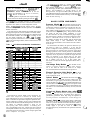
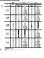
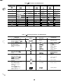
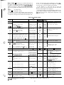
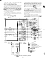
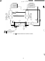
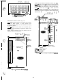
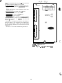
GENERAL
The contrwsm
consists of a processor module (PSIO)9
a low-voltage relay module (DSIO-LV), 2 EXVs, an EXV
driver module (DSIO-EXV), a 6-pack relay board, a keypad and display module (also called HSIO or LID), thermistors, and transducers to provide inputs to the
microprocessor. An options module (SIO) is used to provide additional functions. This module is standard on 30GN
modules and is a field-installed accessory on the 30GT Flotronic II units. See Fig. 1.
IMPORTANT: This publication contains controls, operation and troubleshooting data for 3OGNO40-420
and
30GT225, 250, and 280 FlotronicTM II chillers,
Circuits are identified as circuits A and B, and compressors are identified as Al, A2, etc. in circuit A,
and BI, B2, etc. in circuit B.
Use this guide in conjunction with separate Installation Instructions booklet packaged with the unit,
The 30G Series standard Flotronic II chillers feature
microprocessor-based electronic controls and an electronic
expansion valve (EXV) in each refrigeration circuit.
NOTE: The 30GN040 and 045 chillers with a factoryinstalled brine option have thermal expansion valves (TXV)
instead of the EXV.
Unit sizes 240,270, and 300-420 are modular units which
are shipped as separate sections (modules A and B). Installation instructions specific to these units are shipped inside
the individual modules. See Table 1 for a listing of unit
sizes and modular combinations. For modules 24OB and 270B,
follow all general instructions as noted for unit sizes OSO110. For all remaining modules, follow instructions for unit
sizes 130-210.
MAJOR SYSTEM COMPONENTS
Processor Module - This module contains the operating software and controls the operation of the machine. It
continuously monitors information received from the various transducers and thermistors and communicates with the
relay modules and &pack relay board to increase or decrease the active stages of capacity. The processor module
also controls the EXV driver module, commanding it to open
or close each EXV in order to maintain the proper superheat entering the cylinders of each lead compressor. Information is transmitted between the processor module and relay module, the EXV driver module, and the keypad and
display module through a 3-wire communications bus. When
used, the options module is also connected to the communications bus.
For the Flotronic II chillers, the processor monitors system pressure by means of 6 transducers, 3 in each lead compressor. Compressor suction pressure, discharge pressure,
and oil pressure are sensed. If the processor senses high
discharge pressure or low suction pressure, it immediately
shuts down all compressors in the affected circuit. During
operation, if low oil pressure is sensed for longer than one
minute, all compressors in the affected circuit are shut down.
At start-up, the coil pressure signal is ignored for 2 minutes. If shutdown occurs due to any of these pressure faults,
the circuit is locked out and the appropriate fault code is
displayed.
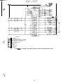
Table 1 - Unit Sizes and Modular Combinations
NoT”o’NNs”L
UNIT MODEL
30G NO40
3OG NO45
30GN050
30EN060
30GN070
30GN080
SE\WlK&N
ssE%~N
-
40
45
50
60
70
80
-
-
Low-Voltage Relay Module - This module closes
30GNlfO
30GN190
30GN210
30GT225
30GN240
30GT250
30GN270
30GT280
30GN300
_...--30GN330
30GN360
30GN390
30GN420
1
160
180
200
225
225
250
260
280
1
285
1
325
350
380
400
I
-
I
30QN170
-
-
Electronic Expansion Valve Module - This module receives signals from the processor and operates the electronic expansion valves.
30GNlOO
-
30GN130
1
contacts to energize compressor unloaders and/or compressors. It also senses the status of the safeties for all compressors and transmits this information to the processor.
I
Options Module - This module allows the use of Flotronic II features such as dual set point, remote reset, demand limit, hot gas bypass, and accessory unloaders. The
options module also aIlows for reset and demand limit to be
activated from a remote 4-20 mA signal. The options module is installed at the factory on 040-210 and modular 240420 units. It is a field-installed accessory for 225, 250 and
280 units.
30GNi 00
-
1 30GNi 3 0 1
3 0 G N f 70
30GNl70
30GN170
30GN190 3 0 G N f 90/30GN170*
30GN190
30GN210
30GN210
30GN210
*60 Hz units/50 Hz units.
Keypad and Display Module (also called HSlO
or LID) - This device consists of a keypad with 6 function keys, 5 operative keys, 12 numeric keys, and an alphanumeric g-character LCD. Key usage is explained in
Accessing Functions and Subfunctions section on page 28.
The Flotronic II control system cycles compressor unloaders and/or compressors to maintain the selected leaving
water temperature set point. It automatically positions the
EXV to maintain the specified refrigerant superheat entering the compressor cylinders. It also cycles condenser fans
on and off to maintain suitable head pressure for each circuit. Safeties are continuously monitored to prevent the unit
from operating under unsafe conditions. A scheduling function, programmed by the user, controls the unit occupied/
unoccupied schedule. The control also operates a test program that allows the operator to check output signals and
ensure components are operable.
Control Switch - Control of the chiller is defined by
the position of the LOCAL/ENABLE-STOP-CCN switch.
This is a 3-position manual switch that allows the chiller to
be put under the control of its own Flotronic II controls,
manually stopped, or put under the control of a Carrier Cornfort Network (CCN), Switch allows unit operation as shown
in Table 2.
2
,,
:f
c ’ _. ’
ELECTRONIC EXPANSION VALVES
DRIVER MODULE
(DSIO EXV)
LOW-VOLTAGE
RELAY MODULE
d
TB-7
I
(DsroiLv)
g-PACK
RELAY BOARD
B
;rt’EFUCER
SOURCE (PSI)
C O O L E R iEA1
I
‘ER
RELAY, B
,TB-3
FIELD
ZEol
CONNECl
\- -.-...-
KEYPAD;DISPLAY
M O D U L E (HSIO/LID)
GROUND
208/230-,
FAULT
INTERRUPTER
460-f%!-3-60-V
ONLY
LEGEND
CCN
TB
- c Zarrier Comfort Network
-1 “erminal Block
Fig. 1 - 30GN Control Panel (040-110, 240B, 270B Unit Shown)
rlON
In the LOCAL/ENABLE position, the chiller is under local control and responds to the scheduling configuration and
set point data input at its own local interface device (keypad and display module).
In the CCN position, the chiller is under remote control
and responds only to CCN network commands. The occupied/
unoccupied conditions are defined by the network. All keypad and display functions can be read at the chiller regardless of position of the switch.
CCN run or stop condition is established by a command
from the CCN network. It is not possible to force outputs
from the CCN network, except that an emergency stop command shuts down the chiller immediately and causes ‘ ‘ALARM
52” to be displayed.
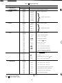
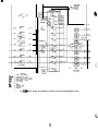
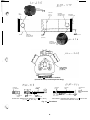
Compressor Protection Control Module (CPCS)
- Each compressor on models 30GN070 (50 Hz), 080100, and 240B, 270B, has its own CPCS as standard equipment. All 30GN040-060 and 070 (60 Hz) units feature the
CPCS as an accessory, and CR (control relay) as standard
equipment. See Fig. 2. The 30GN130-2 10 and associated
modular units and the 30GT225, 250, and 280 Flotronic II
units have a CR as standard equipment. The CPCS or CR is
used to control and protect the compressors and crankcase
heaters. The CPCS provides the following functions:
compressor contactor control
crankcase heater control
compressor ground current protection
status communication to processor board
high-pressure protection
The CR provides all of the same functions as the CPCS
with the exception of compressor ground current protection. Ground current protection is accomplished by using a
CGF (compressor ground fault) board in conjunction with
the CR. The CGF provides the same ground fault function
as the CPCS for units where the CPCS is not utilized.
One large relay is located on the CPCS board. This relay
(or CR) controls the crankcase heater and compressor
contactor. The CPCS also provides a set of signal contacts
that the microprocessor monitors to determine the operating
status of the compressor. If the processor board determines
that the compressor is not operating properly through the
signal contacts, it will lock the compressor off by deenergizing the proper 24-v control relay on the relay board. The
CPCS board contains logic that can detect if the current-toground of any compressor winding exceeds 2.5 amps. If
this condition occurs, the CPCS module shuts down the
compressor.
A high-pressure switch with a trip pressure of 426 +
7 psig (2936 +_ 48 kPa), is wired in series with the CPCS.
If this switch opens during operation, the compressor stops
and the failure is detected by the processor when the signal
contacts open. The compressor is locked off. If the lead
compressor in either circuit is shut down by the high pressure switch or ground current protector, all compressors in
the circuit are locked off.
Table 2 - LOCAL/ENABLE-STOP-CCN
Switch Positions and Operation
SWITCH
POSITION
STOP
LOCAL/ENABLE
CCN
:t2 1
I
UNIT
OPERATION
CONFIGURATION AND
SET POINT CONTROL
Keypad Control 1 CCN Control
I Unit Cannot Run Read/Write
1 Read Only
Unit Can Run
Read/Limited Write Read Only
Unit Cannot Run Read Only
ReadlWrite
Read/Limited
Unit Can Run
Read Onlv
Write
Electronic Expansion Valve (EXV) - The microprocessor controls the EXV through the EXV driver module. Inside the expansion valve is a linear actuator stepper
motor.
The lead compressor in each circuit has a thermistor and
a pressure transducer located in the suction manifold after
the compressor motor. The thermistor measures the temperature of the superheated gas entering the compressor cylinders. The pressure transducer measures the refrigerant
pressure in the suction manifold. The microprocessor converts the pressure reading to a saturated temperature. The
difference between the temperature of the superheated gas
and the saturation temperature is the superheat. The microprocessor controls the position of the electronic expansion
valve stepper motor to maintain 29 F (16 C) superheat.
At initial unit start-up, the EXV position is at zero. After
that, the microprocessor keeps accurate track of the valve
position in order to use this information as input for the
other control functions. The control monitors the superheat
and the rate of change of superheat to control the position
of the valve. The valve stroke is very large, which results
in very accurate control of the superheat.
Sensors - The Flotronic TM II chiller control system gathers information from sensors to control the operation of the
chiller. The units use 6 standard pressure transducers and
4 standard thermistors to monitor system pressures and temperatures at various points within the chiller. Sensors are
listed in Table 3.
Table 3 - Thermistor and Transducer Locations
Sensor
T:
Ti
TIO
Sensor
DPT-A
SPT-A
OPT-A
DPT-I3
SPT-B
OPT-B
THERMISTORS
Location
Cooler Leaving Water Temp
Cooler Entering Water Temp
Compressor Suction Gas Temp Circuit A
Compressor Suction Gas Temp Circuit B
Remote Temperature Sensor (Accessory)
PFIESSURETRANSDUCERS
Location
Compressor Al Discharge Pressure
Compressor Al Suction-Pressure
Compressor Al Oil Pressure
Compressor Bl Discharge Pressure
Compressor Bi Suction Pressure
Compressor Bl Oil Pressure
PROTECTION
BOARD
Fig. 2 - Compressor Protection Control Module
4
OPERATION
ically reset by the return temperature reset or space and outdoor air temperature reset features. It can also be reset from
an external 4-20 mA signal with a loop isolator, or from a
network signal.
The operating sequences shown are some of many possible loading sequences for the control of the leaving water
temperature. If a circuit has more unloaders than another,
that circuit will always be the lead circuit.
DATA
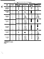
Capacity
Control - The control system cycles
compressor to give capacity control steps as shown in
Tables 4A-4D. The unit controls leaving chilled water temperature. Entering water temperature is used by the microprocessor in determining the optimum time to add or subtract steps of capacity, but is not a control set point.
The chilled water temperature set point can be automat-
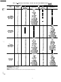
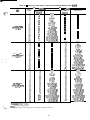
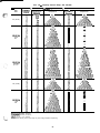
Table 4A - Capacity Control Steps, 040-070
UNIT
30GN
CONTROL
STEPS
:
“““ft Hr)
i
LOADING SEQUENCE A
%
Displacement
Compressors
(AwrW
Al*
::
APB1
1~~
Al :Bl
Al*
25
y-yy
,
:
i
%
100
040 (60 Hz)
045 (60 Hz)
AIt
:
s;
040 (50 Hz)
0:; pg~l
,
040 (50 Hz)
o;y;,y
,
045 (50 Hz)
:
1
:
4
5
1
:
4
i
1
::
Al% *
Al ‘,Bl
Al ,Bl
-
1::
-
Al*
Al
Al *,Bl
Al ,Bl
Al*
i:
:
:A
:
5
8°F
100
:
;:
:
5
1
is;
100
18
045 (50 Hz)
:
yfyy2
I
::
56
z
6
7
1
045 (50 Hz)
32
4
045 (50 Hz)
050A\6$Hz)
25
50
1::
-
-
Bl*
AIBlil *
Al’,Bl
-
-
Bl*
:;
1::
045 (50 Hz)
050 (60 Hz)
Alt,Bl**
Al”B1
Al ,k
Al*
1;:
24
;
4
050f”, Hz)
Al”B1
Al ,kl
Al”
LOADING SEQUENCE B
%
Displacement
Compressors
tAppro
i
7
Al% *
Al ‘,Bl
Al ,Bl
A2-y
y&tgi
Al ,i31
A2.p
Al;Bl*
Al +,Bl
Al *,Bl
Al ,Bl
-
2
100
-
*Unloaded compressor.
tCompressor unloader, standard.
**Compressor unloader, accessory.
ttTwo unloaders, both unloaded.
5
El
100
Al& *
Al ,‘sl*
Al .Bl
::
53
i:
100
-
-
38
Bl”
::
Al% *
Al,k
Al .Bl
1%
-
-
El
z7
64
1::
Al ,Bl
Table 4A - Capacity Control Steps, 040-070 (cant)
I
LOADING SEQUENCE A
LOADING SEQUENCE B
%
UNIT
30GN
.
.
.
Compressors
Displacement
tApw0
Al*
-
a
I
1
I
Compressors
18
?I
56
73
050 (50 Hz)
Y
1:;
1
28
Al”B1
Al ,k
Al*
060G Hz)
050 (50 Hz)
“g pgy
I
Bl*
Al% *
Al’,Bl
Al ,Bl
Al&l’
Al ,‘sl*
Al ,Bl
-
A&t!
050 (50 Hz)
060A\~**Hz)
#$Vg,
Al ,‘sl
yi!
050 (50 Hz)
06g$,y
I
-
-
-
-
6
-
1
15
A;p
18
Bs’lt,t
z:
Al~~Bl*
A$t!g’
060 (50 Hz)
070fc Hz)
Al ,‘sl
Al*
Al”Bl
Al ,i31
Al*
Al% *
Al ‘.Bl
Al @I
060 (50 Hz)
07Odpto**Hz)
A:$
AV$B1
Al .Bi
060 (50 Hz)
oypg~)
,
*Unloaded compressor.
j-Compressor unloader, standard.
**Compressor unloader, accessory.
ttTwo unloaders, both unloaded.
8600
100
-
“d,i;t)
Al’,Bi
Bl*
zi
66
83
100
-
-
Ei:
83
100
Al&’
Al .i31*
Ai,Bl
-
i
-
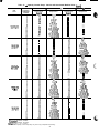
Table 4A - Capacity Control Steps, 040-070 (cant)
T
LOADING SEQUENCE A
UNIT
30GN
1_. .
i
;.
%
Displacement
tApprod
Compressors
16
060
(50 Hz)
LOADING S WENCE B
%
Displacement
(Approx)
i!
2:
ii:
:i
100
“‘“G Hz)
2
65
i;
100
83
100
Al*
A-FBI
Al ,k
Al l ,A2,Bl
Al ,A2.B1
Al”
-
Al& *
Al ,‘sl*
Al ,Bl
Al*,A2,Bl*
Al .A2.B1*
Ai’,A2’,Bl
l
-
15
-
-
::
57
ii
Hz)
Al t**,Bl**
070 (50
*Unloaded compressor.
tCompressor unloader, standard.
**Compressor unloader, accessory.
ttTwo unloaders, both unloaded.
-
Bl*
Al%
Al fB1
Al ,Bl
Al *,A2,Bl*
Al *,A2,Bl
Al ,A2,Bl
oy&ya
,
Al’,61
-
-
ylf,t
Al&
Al :Bt
Al ,A2,Bl*
Al .A2.B1
l
A&’
Al :Bl
Al ,A2,Bl*
Al ,A2,Bl
-
,
Table 4B - Capacity Control Steps, 080-110 and Associated Modular Units
I
r
LOADING SEQUENCE A
UNIT
30GN
Compressors
Al*
Al
Al*,Bl*
Al *,Bi
Al ,Bl
Al *,A2,Bl
Al .A2.B1
::
iii
100
-
Al”
Al+yBl*
AA’;Jgl
Al ,Bl
Al *.A2.B1
Al ,A2,Bl
-
Displacement
(4wW
z!
Aiti
-
LOADING SEQUENCE B
%
-
08Aqy;,y
,
-
A$-hJ
Ai,Bl
Al ,A2,61*
Al ,A2,Bl
Be’lt,t
A;{:;:)
Al+yBl*
Al ++,Bl
Al *,Bl
Al ,Bl
Al *.A2.B1
Al ,k2,Bl
Al*
Al’,Bl
Ai,A2,Bl*
Al ,A2,Bl
-
Al% *
Al $1
Al ,Bl
Al *,A2,Bl*
Al *,A2,Bl
Al ,A2,Bl
A&*
Al,‘Bl*
Al ,Bl
Al *,A2,Bi *
Al ,A2,Bl*
Al .A2.B1
, ,
Bl*
Al t t
Al*
-
Al+?Bl*
AWtSg
Al ,Bl
Al ++,A2,Bl
l
A4l&pi’&
Al .A2,Bl
080 ( S O H z )
Aif”*,6if**
Bl*
Bi
Ai*,Bl*
Al,Bl*
Al ,Bl
Al .A2.81*
Ai,A2,Bi
y-/i+
Al t t
Ai*.
080 (60 Hz)
Aly*,Blv
Compressors
-
-
B1 t t
Bl*
-
AIB:l *
Ai,61
Al *,A2,Bl++
A;;“A’;“Wt
A;.$!
y&f
Al+?Bl*
AJ&t,$
Al ,Bl
Al ++,A2,Bl*
AAit,-bA&l
Al ,A2,Bl
*Unloaded compressor.
+Compressor unloader, standard
**Compressor unloader, accessory
++Two unloaders, both unloaded.
NOTE: These capacity control steps may vary due to lag compressor sequencing.
Ai.A;,Bl
AIBlk *
Ai,Bl
Al *,A2,B1++
“d;“A’;“B’lt’t
Ai,Ai,Bi
-
-
Table 4B - Capacity Control Steps, 080-110 and Associated Modular Units (cant)
lUNIT
30GN
CONTROL
STEPS
LOADING ! iQUENCE A
%
Displacement
Compressors
VNwW
LOADING 1 :QUENCE B
%
Displacement
Compressors
(Approx)
Al*
Bl*
:;
;;
Al% *
Al ‘,Bl
Al ,Bl
Al *,A2,Bl*
Al *,AZ,Bl
Al ,A2,Bl
Al *,A2,Bl *,B2
Al *,A2,Bl ,B2
Al ,AZ,Bl,B2
E
53
65:
ii
91
A2.p
A;,%&1
Hz)
Aly*,Blt
090 (60
Al*:B 1
A;!tf2UJ$
Al*A2 bl
Al tT,A2,i31 ,B2
Al *,A2,Bl ,B2
Al ,A2,Bl ,B2
-
-
ii
2;
r3:
::
100
-
-
Al%*
Al,Bl*
Al ,Bl
Al *,Bl l ,B2
Al ,Bl *,B2
Al,Bl,B2
Al *,A2,Bl *,B2
Al ,A2,Bi *,B2
Al .A2.B1 .B2
-
A;,:&>
Al’,Bl
Al ,Bl tT,B2
Al ,Bl *,B2
Al ,Bl ,B2
Al ,A2,Bl t-t,82
Al .A2.B1 *.B2
Al’,A&Bl ,B2
Bitt
BP’
“d,:;tJ
Hz)
Alt**,BlY*
Ai,Bl
AAli BB’lt,t~~2
090 (60
Al *,A2,Bl
Al ,A2,Bl
Al tt,A2,Bl ,B2
Al*,A2,Bl ,B2
Al ,A2,Bl ,B2
Al*
80
82
91
Al%1 *
Al ‘,Bl
Al ,Bi
Al *,A2,Bl*
Al *,A2,Bl
Al ,A2,Bl
Al *,A2,Bl:,B2
Al *.A2.B1 .B2
Al ,k2,Bi ,B2
Al& *
Al ,Bl*
Al ,Bl
Al*,Bl*,B2
Al,Bl*,B2
Al ,Bl ,B2
Al*,A2,Bl *,B2
Al .A2.Bl *.B2
Al’,Ai,Bi ,B2
A;:!
Al;; Bl
Al*,Bl
Al ,Bl
Al tt,A2,81
Al tt,AP,Bl
Al *,A2,61
Al ,A2,Bl
Altt,A2,Bl*,B2
Al tt,A2,Bi ,B2
Al *,A2,Bl ,B2
Al .A2.61 .B2
l
*Unloaded compressor.
tCompressor unloader, standard.
**Compressor unloader, accessory
TtTwo unloaders, both unloaded.
NOTE: These capacity control steps may vary due to lag compressor sequencing.
9
Ai,Bl ,B2
Al ,A2,Bl TT,B2
Al .A2.Bl*.B2
Al’,Ai, Bl ,B2
Bi*
-
-
-
Table 4B - Capacity Control Steps, 080-110 and Associated Modular Units (cant)
UNIT
30GN
CONTROL
STEPS
r
T
LOADING
%
Displacement
(APPW
Compressors
-
090 (50 Hz)
Alt,Bly
-
-
-
A$!!
Displacement
(4wW
7
ii
43
Pii
60
7”:
Ei
100
AltAt Bl
Al*,&
Al ,Bl
Al Tt,A2,Bl*
Al Tt,A2,Bl
Al *,A2,61
Al ,A2,Bt
Al tt,A2,Bl *,B2
Al Tt,A2,Bl ,B2
Al *.A2.B1 .B2
Al ,A2,i31,‘82
100,24OB,
270B (60 Hz)
Alt**,Blt
100,24OB,
270B (60 Hz)
Alt,Blt^*
i
10
-
-
A1’,Bl*k
Al *,A2,Bitt,Bl
Al ,A2,BlTt,Bl
A.i‘J;,;; i;2
II I
BB’.p
Al’,Bl*
Al*,Bltt,B2
Al ,Bi TT,B2
Al ,Bl”,B2
Al ,Bl ,B2
Al tt,AZBl tt,B2
Al *,A2,Bl j-T,B2
Al ,A2,Bl TT,B2
Al ,A2,61*,62
Al ,A2,Bl B2
Al*
Al% *
Al ‘,Bl
Al ,Bl
Al *,A2,Bl*
Al *,A2,Bf
Al ,A2,Bl
Al *,A2,Bi*,B2
Al *,A2,Bl ,B2
Al ,A2,Bl ,B2
Al *,A2,& *,B2
Al *,A2,Bl ,B2
Al ,A2,Bl ,B2
“Alt!
Al*,BlTT,BZ
“d;B~ltt~~2
A;;:;H
Al% *
Al (61
Al ,Bl
Al *,A2,Bl*
;;*J.p;
2408,
Compressors
:;’
Al;; Bl
Al +I
Al ,Bl
Al tt,AZBl tt
Altt,A2,Bl*
AlTT,A2,Bl
Al *,A2,Bl
Al ,A2,Bl
Al tt,A2,Bl *,B2
Al TT,A2,Bl ,B2
Al*,A2,Bl ,B2
Al .A2,Bl .B2
Al*
090 (50 Hz)
Al t**,Bl t**
100,
LOADING SEQUENCE B
%
-
-
Ai,-Bi
Al*.Bltt.B2
Al ,A2,BltT,B2
Al .A2.B1 *.B2
Al’,A$Bl ,B2
*Unloaded compressor
+Compressor unloader, standard.
**Compressor unloader, accessory.
TtTwo unloaders, both unloaded.
NOTE: These capacity control steps may vary due to lag compressor sequencing
10
Table 40 - Capacity Control Steps, 080-I IO and Associated Modular Units (cant)
LOADING SEQUENCE A
%
UNIT
30GN
Displacement
(Awr ox)
8
Compressors
Altt
r
LOADING
%
Displacement
(Apex)
8
EQUENCE B
Compressors
Bitt
Bl*
Al*
:i
A$;g
100, 2406,
270B (60 Hz)
Alr*,Blr
100
:;
26
100, 240B,
2708 (50 Hz)
A1tW-t
100
7
100, 240B,
2708 (50 Hz)
Aft**,Blt
Wtf2Z$’
;
9
E
14
:
:
5
6
8’
9
::
12
::
100, 2408,
270B (50 Hz)
Alr*,Blt”*
A l % *
Al :Bl
A1 ,Bl
A l *,A2,Bl*
Al *,A2,Bl
Al ,A2,Bl
Al *,A2,Bl *,B2
Al*.A2.81 .B2
Al ,‘A2@1,82
Al t t
Al*
i
::
100, 2408,
270B (50 Hz)
Alt,Blt**
Al ,bl
Al tt,A2,61*
Al tt,A2,61
Al *,A2,Bl
Al ,A2,Bl
Al tt,A2,Bl *,B2
Al tt,A2,Bl ,B2
Al *,A2,Bi $32
Al .A2.B1 .B2
Al*
-
Al ,kI2,i31
Altt,A2,Bl *,B2
Al tt,A2,Bl ,B2
Al *,A2,Bl ,B2
Al .A2.Bl.B2
Altt
-
:A
20”
::
;“7
E100
Al “B: tt
Ai,Bl*
Al ,Bl
Al*,Bltt,B2
“A;“B’lt”tb;2
Al’,Bl ,b2
Al *,A2,Bl tt,B2
Al ,A2,Bi tt,B2
Al ,A2,Bl l ,BZ
Al .A2,Bl ,B2
Bl*
Al% *
Al,bl*
Al ,Bl
Ad;g *‘8822
Al’,Bl*b2
Al *,A2$1 *,B2
Al .A2.B1 l .B2
Al’,Ai,Bl ,B2
-
Bitt
Bl*
Ai,F;hJ
Al’,Bl
Al*,Bl tt.132
Al ,‘Bl ff,‘B2
Al ,Bl *,B2
Al ,Bl,B2
Al*,A2,Bl tt,B2
Al ,A2,Bl tt,B2
Al .A2,Bl *.B2
:
Al*
i
A;,;h; 1
ii
Al ,‘sl
Al tt,AZBl tt
A l tt,A2,Bl*
“A’p/pg
Al :li t+
Ai,Bi*
Al,Bl
Al tt,Bl tt,B2
Al *,Bl tt,B2
AAlj “B’(t;3122
A1*iI2 bl
Al tt,/i2,Eil tt,B2
Altt,A2,Bl*,B2
Altt,A2,Bl ,B2
Al l ,AZ,Bl ,B2
Al ,A2,Bl ,B2
Al’,Bl ,b2
Al tt,AZBl tt,B2
Al *,A2,Bl tt,B2
Al ,A2,Bl tt,B2
Al ,A2,Bl *,B2
Al ,A2,Bl ,B2
;
9
::
E
::
16
*Unloaded compressor.
tCompressor unloader, standard
**Compressor unloader, accessory.
tfTwo unloaders, both unloaded.
NOTE: These capacity control steps may vary due to lag compressor sequencing.
11
Table 48 - Capacity Control Steps, 080-110 and Associated Modular Units (cant)
LOADING SEQUENCE A
UNIT
30GN
%
Displacement
(ApprW
Compressors
Al*
&I *
14
;A
::
s6:
2
r
LOADING SEQUENCE B
%
Displacement
(Amrox)
81”
Al51 *
Al,Bl*
Al ,Bl
;;*gg
Al ‘,Bl
Al ,Bi
Al l ,A2,Bl*
Al *,A2,Bi
Al ,A2,Bl
Al*,A2,Bl*,B2
Al *.A2.B1 .B2
Al ,A2,Bl ,i32
A/p
A;;;#
Al ,Bl
Al Tt,A2,Bl*
Al t-/-,A2,Bl
Al*,A2,Bl
Al ,A2,Bi
Al Tt,A2,Bl *,B2
Al -ft,A2,Bi ,B2
Al *.A2.B1 .B2
Al ,k2,Bl ,B2
Compressors
Ai’,Bl ,B2
Al*,A2,Bl*,B2
Al ,A2,Bl *,B2
Al ,A2,Bl ,B2
-
-
1
-
B1 t t
Bl*
-
-
110 (60 Hz)
Al t**,Bl Y
110 (50 Hz)
Alt,Blt
*Unloaded compressor.
TCompressor unloader, standard
**Compressor unloader, accessory.
TtTwo unloaders, both unloaded.
NOTE: These capacity control steps may vary due to
Al !% tt
Ai ,Bi*’
Al ,Bl
Al*,BlTT,B2
“A; BB’~t;3”2’
Al’,Bl ,B2
Al *,A2,Bl tT,B2
Al ,A2,Bl tT,B2
Al ,A2,Bl *,B2
Al ,A2,Bl ,B2
A’tt
Al”
y&v
A;;hgl
A;,=.$
Al ,Bl
A’tt,AZBl
tt
Al tt,A2,Bl*
Ai,Bl
Al *,Bl tT,B2
“A; B!&lW22’
$-t&Z3
Al ,A2,Bl
Al tt,A2,Bl *,B2
Al Tt,A2,Bl ,B2
Al*.A2.B1 .B2
Al ,A2,Bl ,B2
Al*
Ai,Bl ,B2
Al ttNB’ttB2
Al *,A2,Bl tt,B2
A-l ,A2,Bl tT,B2
Al .A2.B1 *.B2
Al’,Ai,Bl ,i32
Bl*
Al% *
Al’,Bl
Al ,Bl
Al *,A2,Bl*
Al l ,A2,Bl
Al ,A2,61
Al *,A2,Bl *,B2
Al *,A2,Bl ,B2
Al .A2Bl .B2
Al%
Al ,Bt*
Al ,Bi
Al l ,Bl *,B2
Al ,Bl *,B2
Al ,Bl ,B2
Al *,A2,Bl *,B2
Al .A2,Bl*.B2
A;,Ai,Bl ,B2
lag compressor sequencing
12
100
Table 4B - Capacity Control Steps, 080-110 and Associated Modular Units (cant)
LOADING SEQUENCE A
UNIT
30GN
CONTROL
STEPS
%
Displacement
UWrW
Compressors
A2.p
*$#l
110 (50 Hz)
Alt**,Blt
Al ,Bl
“A:tkA2’i3BI~
-
110 (50 Hz)
Alt,Blv
AleA2 Bl
Al tf,A2,Bl ,B2
Al *,A2,Bl ,B2
Al ,AZ,Bi ,B2
-
a
*;$T
:
110 (50 Hz)
Alt**,Blt**
Al;; Bl
Al *,Bl
Al ,Bl
*&Wf22il”l’
z
i
9
Al*A2 Bl
Al tt,A2,Bi ,B2
Al *,A2,Bl ,B2
Al ,A2,Bl ,B2
::
12
*Unloaded compressor.
TCompressor unloader, standard.
**Compressor unloader, accessory
TTTwo unloaders, both unloaded.
NOTE: These capacity control steps may vary due to lag compressor sequencing
13
T
LOADING : ,QUENCE B
%
Displacement
Compressors
(Arwox)
-
-
Be’lt,t
*;,F;:t
Al’,Bl
“A;W&3$
Ai,Bi ,B2
Al ,A2,Bl tt,B2
Al ,A2,Bf *,82
Al .A2,Bl ,B2
a
“B’p
~,;~~J
AI’,Bl
Al ,BltT,B2
Al ,Bl *,B2
Al ,Bi ,B2
Al ,A2,Bl tt,B2
Al ,A2,B1 *,B2
Al .A2.B1 .B2
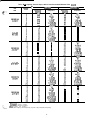
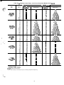
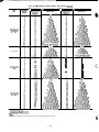
Table 4C - Capacity Control Steps, 130-210 and Associated Modular Units
UNIT
30GN
T-
LOADING
%
Displacement
Mvrox)
:‘:
:fz
130, 240A,
2;
;i
Ei
100
r
EQUENCE A
Compressors
Al*
130, 240A,
130, 240A,
130,24OA,
EQUENCE B
Compressors
Bl*
Al% *
Al ‘,Bl
Al ,Bl
Al *,A2,Bl*
Al *,A2,Bl
Al ,A2,Bl
Al *,A2,Bi *,B2
Al*,A2,Bl ,B2
Al .A2.B1 .B2
’ Al’tt ’
Al*
AlgBl’
A$t;l”i’
Al ,kH
Al tt,A2,Bi *
Al tt,A2,B1
Al *,A2,Bl
Al ,A2,Bl
Al tj-,A2,Bi*,B2
Al tt,A2,Bl ,B2
Al *.A2.B1 .B2
A? ,iI2,-Bl ;B2
130, 240A,
LOAD11
%
Displacement
VVwr ox)
:i
z
2;
;:
K
100
-
-
Al&’
Al ,k*
Al ,Bl
Al l ,Bl l ,B2
Al ,Bi *,B2
Al ,Bl ,B2
Al?,A2,Bl *,B2
Al ,A2,Bf*,B2
Al ,A2,Bl ,B2
-
‘-
-
-
Al’,Bl ,k2
Al *,A2,Bl tt,B2
Al ,A2,Bl tt,B2
Al ,A2,Bl *,B2
Al ,A2,Bl ,B2
yp
BB’!!
AlRBl’
AAlt,t&’
Al*%++
Al ,kl
Al ttA2,Bl tt
Al tt,A2,Bl*
Al tt,A2,Bi
Al *.A2.B1
Al ,iI2,‘Bi
Al ttAW1 tt,B2
Al tt,A2,Bl *,B2
Al tt,A2,Bl ,B2
Al *.A2,Bl .B2
Al ,k2&,82
Al*
Al.,Bl
Al t-t-41 tt,B2
Al *,Bl tt,B2
“A; BB’~~~~2
-
BJ.fJ
;-y;;;;
Ai,Bi*
Al ,Bl
Al *,Bl tt,B2
“A;B&t$&2
A&l *
Al ‘,Bl
Al ,Bl
Al *,A2,Bl
Al *,A2,Bl
Al ,A2,Bl
Al *,A2,Bl *,B2
Al*,A2,Bl ,B2
Al ,A2,Bl ,B2
Al *,A2,A3,Bl
*,B2
Al *,A2,A3,Bl
,B2
Al .A2.A3.Bi
.B2
l
*Unloaded compressor
tCompressor unloader, standard.
**Compressor unloader,
accessory
ttTwo unloaders, both unloaded
NOTE: These capacity control steps may vary due to lag compressor sequencing+
14
Al’,Bl ,k2
Altt,A2,Bltt,B2
Al l ,A2,Bl tt,B2
Al ,A2,Bl tt,B2
Al .A2.B1 *.B2
Al’,A2’,Bl ,i32
Bl*
Al& *
Al,kl*
Al ,Bl
Al *,Bl *,B2
Al ,Bl *,B2
Al ,Bl ,B2
Al*,A2,Bl *,B2
Al ,A2,Bl*,B2
Al ,A2,Bl ,B2
Al *,A2,A3,Bl *,B2
Al qA2qA3.81 *.B2
Table 4C - Capacity Control Steps, 130-210 and Associated Modular Units (cant)
UNIT
30GN
CONTROL
STEPS
r
LOADING SEQUENCE A
%
Displacement
Compressors
6
“drt,t
AlPtlBl*
Al tt,Bl
Al l ,Bl
Al ,Bl
Al tt,A2,Bl*
“A’:t;P22~7El
130, 24OA,
130, 240A,
LOADING SEQUENCE B
%
hwrox)
130,24OA,
T
-
Al*A2 Bl
Al tt,A2,Bl *,B2
Altt,A2,Bl ,B2
Al *,A2,Bi ,B2
Al ,A2,Bl ,B2
Al tt,A2,A3,Bl *,B2
Al tt,A2,A3,Bl ,B2
Al *,A2,A3,Bl ,B2
Al ,A2,A3,Bl
,B2
-
Displacement
(Awrox)
-
Compressors
Bitt
Bi*‘
AIB& *
Al’,Bl
Al *,Bl tt,B2
Al ,Bl tt,B2
Al ,Bl *,B2
Al ,Bl ,B2
Al ,A2,Bl tt,B2
Al ,A2,Bl*,B2
Al ,A2,Bl ,B2
Al ,A2,A3,Bl
tt,B2,B3
Al ,A2,A3,Bi
*,B2,B3
Al ,A2,A3,Bl
,B2,B3
A$v
B;.p
Al;t:Bl*
A;;Jbg’
AIBIL *
Ai,Bi
Al l ,Bl tt,B2
Al .Bl tt.B2
At ,Bf’*;B2
Al ,Bl ,B2
Al .A2.B1 tt.B2
Ai ,A2,Bl’*;B2
Al ,A2,Bl ,B2
Al ,A2,A3,Bl
tt,B2
Al ,A2,A3,Bl l ,B2
Al ,A2,A3,Bl
,B2
-
Al ,Bl
Al tt,A2,Bl*
A;~tA$2’~1
Al*A2 Bl
Altt,;22,Bl*,B2
Al tt,A2,Bl ,B2
Al *,A2,Bi ,B2
Al ,A2,Bl ,B2
Al tt,A2,A3,Bl*,B2
Altt,A2,A3,Bi ,B2
Al*,A2,A3,Bl ,B2
Al ,A2,A3,Bl
,B2
Al’
Al
Al *,Bl*
Al *,Bl
Al ,Bl
Ai*,A2,Bl*
Al l ,A2,Bl
Al ,A2,Bi
Al *,A2,Bi l ,B2
Al *,A2,Bl ,B2
Al ,A2,Bl ,B2
Al*,A2,A3,Bl *,B2
Al *,A2,A3,81
,B2
Al ,A2,A3,Bl
,B2
*Unloaded compressor.
tCompressor unloader, standard.
**Compressor unloader, accessory
ttTwo unloaders, both unloaded.
NOTE: These capacity control steps may vary due to lag compressor sequencing.
15
-
-
Bi*
A&l *
Al ,Bl*
Al ,Bl
Al *,Bl *,B2
Al ,Bl *,B2
Al ,Bl ,B2
Al l ,A2,Bl l ,B2
Al ,A2,Bl *,B2
Al ,A2,Bl ,B2
Al l ,A2,A3,Bl *,B2
Al ,A2,A3,Bl*,B2
Al ,A2,A3,Bl
,B2
Table 4C - Capacity Control Steps, 130-210 and Associated Modular Units (cant)
UNIT
30GN
LOADING
%
Displacement
(Apwxl
6
EQUENCE A
Compressors
y-p
AlPtlBl’
“Att;l”l’
::
:“;
zi
49
53
ii
i:
ii:
95
100
Al ,‘sl
AWh$Y;
Al ,A2,&
Altt,A2,Bi*,B2
Al tt,A2,Bl ,B2
Al *,A2,Bl ,B2
Al ,A2,Bl ,B2
Al tt,A2,A3,Bl ,B2
Al *,A2,A3,Bl
,B2
Al .A2.A3.81 .B2
-
15Aq y4
I
LOADING
%
Displacement
UQwrox)
-
-
-
150 (60 Hz)
Aly*,Blt**
r
EQUENCE 8
Compressors
-
-
B1 tt
BPAIBL *
Ai,Bl
Al *,Bl ft,B2
“Ai”B’lt”tb;’
Al’, Bl ,b2
Al ,A2,Bl *,B2
Al ,A2,Bl ,B2
Al ,A2,A3,Bl
*,B2
Al .A2,A3,Bl ,B2
$y!
Bitt
Al;Bl*
Al tt’,Bl
Al *,Bi
Al ,Bl
A l tt,A2,Bl
Al *,A2,Bl
Al ,A2,81
Al tt,A2,Bl *,B2
Al tt,A2,Bl ,B2
Al *,A2,Bl ,B2
Al ,A2,Bl ,B2
Altt,A2,A3,Bi ,B2
Al *,A2,A3,Bl
,B2
Al ,A2,A3,Bl
,B2
Ai*
AIBIL *
Al ;kBl
Al *,Bl tt,B2
“A;B~ltti3”2’
Bl*
Al’,Bl*i32
Al ,A2,Bi *,B2
Al ,A2,Bl ,B2
Al ,A2,A3,Bl
*,B2
Al ,A2,A3,Bl
,B2
-
-
Bl*
Al% *
Al ‘,Bl
Al ,Bl
Ai*,A2,Bl*
Al *,A2,Bl
Al ,A2,Bl
Ai*,A2,Bl*,B2
Al*,A2,Bl,B2
Al ,A2,Bl ,B2
Al *,A2,A3,Bl
*,B2
Al *.A2,A3.B1 .B2
Al ,k2,k3,Bl , B2
Al tt
Al*
Al;; Bl
Al*,&
Al ,Bl
Wh‘v‘&E&’
Al ,h2,1Bl
Al tt,A2,Bl ,B2
Al *,A2,Bl ,B2
Af ,A2,Bl ,B2
Al tt,A2,A3,Bi ,B2
Al *,A2,A3,Bl
,B2
Al ,A2,A3,Bl
,B2
*Unloaded compressor.
tCompressor unloader, standard
**Compressor unloader, accessory.
ttTwo unloaders, both unloaded
NOTE: These capacity control steps may vary due to lag compressor sequencing
16
-
Al&q*
Al ,‘sl*
Al ,Bl
Al *,Bl *,B2
Al ,Bl *,B2
Al ,Bl ,B2
Al *,A2,Bl *,B2
Al ,A2,Bl *,B2
Al ,A2,Bl ,B2
Al *,A2,A3,Bl *,B2
Al ,A2,A3,Bl *,B2
Al ,A2,A3,Bl ,B2
-
-
-
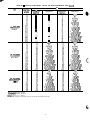
Table 4C - Capacity Control Steps, 130-210 and Associated Modular Units (cant)
SEQUENCE B
LOADING SEQUENCE A
%
UNIT
SIZE
Displacement
(4wrox)
150 (50 Hz)
Alt,Bly*
150 (50 Hz)
Alr*,Blt*”
170, 270A, 300B,
330;; fTtHz)
,
Compressors
Compressors
-
Bitt
-
“A;“B’:t;3”2’
-
Al’,Bl*‘BP
Al ,A2,Bl’tt,B2
Al ,A2,Bl *,B2
Al ,A2,Bl ,B2
Al ,A2,A3,Bltt,B2
Al ,A2,A3,Bl*,B2
Al ,A2,A3,Bl
,B2
A2.p
“B’.p
A+;~;1
A~i~~~~
Al ,‘Bl
Al tt,A2,81
Al *,A2,Bl
Al ,A2,Bl
Al tt,A2,Bl ,B2
Al *,A2,Bi ,B2
Al ,A2,Bl ,B2
Al tt,A2,A3,Bl ,B2
Al *,A2,A3,Bl
,B2
Al .A2,A3,Bl
,B2
Al*
AljBl
Al .Bl tt.B2
Ai ,B1’*;[32
Al ,Bl ,B2
Al ,A2,Bl tt,B2
Al ,A2,Bl *,B2
Al ,A2,Bl ,B2
Al ,A2,A3,Bl
tt,B2
Al ,A2,A3,Bl
*,B2
Al ,A2,A3,Bl,B2
Bl”
Al% *
Al*‘.Bl
Al ,‘Bl
Al *,A2,Bl*
Al ‘,A2,Bl
Al ,A2,Bl
Al *,A2,Bl *,B2
Al *,A2,Bi ,B2
Al ,A2,Bl ,B2
Al *,A2,A3,Bl
*,B2
Al *,A2,A3,Bl ,B2
Al ,A2,A3,Bl
,B2
Al*.A2.A3,Bl *.B2.83
Al ‘,Ai,A$Bl,82,83
Al ,A2,A3,Bl
,B2,B3
A&*
Al ,‘sl*
Al ,Bl
Al *,Bl *,B2
Al ,Bl *,B2
Al ,Bl ,B2
Al*,A2,Bi l ,B2
Al ,A2,Bl *,B2
Al ,A2,Bl ,B2
Al *,A2,Bl *,B2,83
Al,A2,Bl*,B2,B3
Al ,A2,Bl ,B2,B3
Al *,A2,A3,Bl
*,B2,B3
Al ,A2,A3,Bl
*,B2,B3
Al ,A2,A3,Bl
,B2,83
A$!!
AltyBl*
A&tttt;’
Al ,kl
Al tt,A2,Bl*
y&t3g
170, 270A,
3008,
Bl-*.
Al ,i2,kl
Altt,A2,Bl *,B2
Al tt,A2,Bl ,B2
Al *,A2,61 ,B2
Al ,A2,Bl ,B2
Al tt,A2,A3,Bl *,B2
Al tt,A2,A3,Bl ,B2
Al *,A2,A3,Bl
,B2
Al ,A2,A3,Bl
,B2
Al tt,A2,A3,Bl *,B2,B3
Altt,A2,A3,Bl ,B2,B3
Al*,A2,A3,Bl ,B2,B3
Al ,A2,A3,Bl
,B2,B3
*Unloaded compressor.
tCompressor unloader, standard.
**Compressor unloader, accessory
ttTwo unloaders, both unloaded.
NOTE: These capacity control steps may vary due to lag compressor sequencing.
17
-
-
-
Table 4C - Capacity Control Steps, 130-210 and Associated Modular Units (cant)
LOADING SEQUENCE A
r
LOADING SEQUENCE B
%
UNIT
SIZE
Displacement
(Aiwrox)
170, 270A,300B,
Compressors
Compressors
-
yp
-
;-;,q
Ai,Bi*
Al ,Bl
Al*,BItt,B2
“Ai”B’lttb”2’
Al’,Bl*BP
Al *,A2,Bi tt,B2
Al ,A2,Bl tt,B2
Al ,A2,Bl l ,B2
Al ,A2,Bl ,B2
Al *,A2,Bi -ft,B2,B3
Al ,A2,Bltt,B2,B3
Al ,A2,Bl *,B2,B3
Al ,A2,Bl ,B2,B3
Al *,A2,A3,Bl tt,B2,B3
Al ,A2,A3,Bl
tt,B2,63
Al ,A2,A3,Bi
l ,B2,B3
Al .A2.A3.Bl .B2.B3
-
-
Al tt
Al*
Al;Bl*
“Alt;tbT’
300B,
170,27OA,
300B,
33oA/,$cH350
Hz)
9
B;$+
~l*;;{#
A&t$$V;
Ai,Bl*
Al ,Bl
Al *,Bl tT,B2
“A’iBe’~~~22
Al ,A2,Bl
Altt,A2,Bl*,B2
Al tt,A2,Bl ,B2
Al *,A2,B1 ,B2
Al ,A2,Bl ,B2
Al tt,A2,A3,Bi *,B2
Al tt,A2,A3,Bl ,B2
Al”,A2,A3,Bl ,B2
Al ,A2,A3,Bl
,B2
Al tf,A2,A3,Bl *,B2,B3
Al tt,A2,A3,Bl ,B2,B3
Al*,A2,A3,Bl ,B2,83
Al .A2,A3.B1 .B2,B3
Al*
Al’,Bl ,B2
Al *,A2,Bl tt,B2
Al ,A2,Bl tt,B2
Al ,A2,Bi *,B2
Al ,A2,Bl ,B2
Al *,A2,Bl tT,B2,B3
Al ,A2,Bltt,B2,B3
Al ,A2,81*,82,83
Al ,A2,Bl ,B2,B3
Al*,A2,A3,Bl tt,B2,B3
Al ,A2,A3,Bltt,B2,B3
Al ,A2,A3,Bl
*,B2,B3
Al ,A2,A3,Bl
,B2,B3
Bl*
Al% *
Al ‘,Bl
Al ,Bl
Al *,A2,Bl*
Al *,A2,Bl
Al ,A2,Bl
Al *,A2,Bl *,B2
Al *,A2,Bl ,B2
Al ,A2,Bl ,B2
Al *,A2,A3,Bl
*,B2
Al *,A2,A3,Bl
,B2
Al ,A2,A3,Bi
,B2
Al *,A2,A3,Bl
*,B2,B3
Al *,A2,A3,Bl
,B2,B3
Al ,A2,A3,Bl
,B2,83
A&*
Al ,Bl*
Al ,Bl
Al *,Bl *,B2
Al ,Bl *,B2
Al ,Bl ,B2
Al *,A2,Bl *,B2
Al ,A2,Bl *,B2
Al ,A2,Bl ,B2
Al *,AZ,Bl *+B2,B3
Al ,A2,Bl*,B2,B3
Al ,A2,Bl ,B2,83
Al *,A2,A3,Bl *,B2,B3
Al ,A2,A3,Bl*,B2,B3
Al ,A2,A3,Bl ,B2,B3
Al ,Bl
Alft,A2,Bl*
170,27OA,
6
*Unloaded compressor.
tcompressor unloader, standard.
**Compressor unloader, accessory.
ttTwo unloaders, both unloaded.
NOTE: These capacity control steps may vary due to lag compressor sequencing
18
Table 4C - Capacity Control Steps, 130210 and Associated Modular Units (cant)
lUNIT
SIZE
170, 270A, 300B,
33OA/z, t”fB,:“O Hz)
I
CONTROL
STEPS
LOAD11
%
Displacement
(Approx)
SEQUENCE A
Compressors
:
A)$
11
19
Al+yBl*
Altt;3B11
;:
Al ,Bl
Al tt,A2,61*
:i
37
*‘-J-&W~’
:i
z;
::
72
i:
;:
96
100
170, 270A, 3008,
33OA/z, t”609+{,50 Hz)
,
i
-
Al ,1A2,Bl
Al tt,A2,Bl *,B2
Al tt,A2,Bl ,B2
Al *,A2,Bl ,B2
Al ,A2,Bl ,B2
Al tt,A2,A3,Bl *,B2
AlTt,A2,A3,Bl ,B2
Al *,A2,A3,Bl ,B2
Al ,A2,A3,Bl ,B2
Al tt,A2,A3,Bl *,B2,83
Altt,A2,A3,Bl ,B2,B3
Al*,AZ,A3,Bl ,B2,B3
Al ,A2,A3,Bl ,B2,B3
*;p
Al;T’Bl*
Al +,Bl
Al l ,Bl
Al ,Bl
Al t-),*2,61 *
“A! tA$2f,’
170,27OA,
3008,
330~A~~~f\; ff Hz)
,
81
ii;
:A
100
Al*A2 Bl
Alft,A2,B’ltt,B2
Al tt,A2,Bl *,B2
Altt,A2,Bl ,B2
Al *,A2,Bl ,B2
Al ,A2,Bl ,B2
Al tT,A2,A3,Bl tt,B2
Al tt,A2,AS,Bf *,B2
Al tt,A2,A3,Bl ,B2
Al *,A2,A3,Bl
,B2
Al ,A2,A3,Bl
,B2
Altt,A2,A3,Bltt,B2,B3
Altt,A2,A3,Bl*,B2,B3
Al tt,A2,A3,Bl ,B2,B3
Al *,A2,A3,Bl
,B2,B3
Al ,A2,A3,Bi
,BZ,B3
*Unloaded compressor.
j-Compressor unloader, standard
**Compressor unloader, accessory
ttTwo unloaders, both unloaded.
NOTE: These capacity control steps may vary due to lag compressor sequencing.
19
r
LOAD11
i SEQUENCE B
%
Displacement
(APP~~x)
-
-
Compressors
-
I31
Al*,Bltt
*~i~~~~
Al’,Bl
Al *,BlTj-,B2
Al ,Bl tt,B2
A l . B l *.B2
Ai,Bl ,b2
Al*.A2,Bl tt,B2
Al ,A2,Bl ff,B2
Al ,A2,Bl *,B2
Al ,A2,Bl ,B2
Al *,A2,BItt,B2,B3
Al ,A2,Bltt,BZ,B3
Al ,A2,Bl *,B2,83
Al ,A2,Bl,B2,B3
Al *,A2,A3,Bltt,B2,B3
Al .A2.A3,Bl
tt,B2,B3
Ai ,Ai,A$,Bt’*;82,63
Al ,A2,A3,Bl
,B2,B3
BB’!J
;;*;,’ ‘j
Ai,Bl*
Al ,Bl
Al tt,Bl
Al *,Bl tt,B2
“d;“B’W@&’
t-t,82
Al’,Bl*‘BZ
Al *,A2,Bi tt,B2
Al ,A2,Bl TT,B2
Al ,A2,Bl*,E32
Al ,A2,Bl ,B2
Al tt,A2,Bl tt,B2,B3
Al *,A2,Bl tt,B2,B3
Al ,A2,Bi tt,B2,B3
Al ,A2,Bi *,B2,83
Al ,A2,Bl ,B2,83
Al Tt,A2,A3,Bl tt,B2,B3
Ai*,A2,A3,Bltt,B2,B3
Al ,A2,A3,BlTt,B2,B3
Al ,A2,A3,Bl
*,B2,B3
Al ,A2,A3,Bl
,B3,83
Table 4C - Capacity Control Steps, 130-210 and Associated Modular Units (cant)
r
UNIT
SIZE
l-
CKEL
Compressors
Ah
Al j2,B-i
Al ,A2,Bl ,B2
Al ,A2,A3,Bl
,B2
Al ,A2,A3,Bl
,B2,63
Al*
190,36OA/B,
39oEpt Hz)
I
yp;
190,36OA/B,
39;: jfj’;,“”
,
190, 360A/B,
39;; (BGp*w
,
-
Al *,A2,81
Al ,A2,B1
Al *,A2,Bl ,B2
Al ,A2,81 ,B2
Al *,A2,A3,Bl
,B2
Al ,A2,A3,81 ,B2
Al *,A2,A3,Bi
,B2,B3
Al ,A2,A3,Bl
,B2,B3
-
LOADIN<
%
Displacement
OVvW
2
41
56
1;:
-
A%1
Al ,A2,Bi
Al ,A2,Bl ,B2
Al ,A2,A3,Bl
,B2
Al ,A2,A3,Bl
,B2,B3
Al*
fk;
190,36OA,
39;; j:;,W
I
;;*A$&
Al *,A2,& ,B2
Al ,A2,Bl ,B2
Al l ,A2,A3,Bi ,B2
Al ,A2,A3,Bl
,B2
Al *,A2,A3,Bl
,B2,B3
Al ,A2,A3,Bl
,B2,B3
*Unloaded compressor.
tCompressor unloader, standard.
**Compressor unloader, accessory.
TtTwo unloaders, both unloaded
NOTE: These capacity control steps may vary due to lag compressor sequencing
20
Compressors
A1B’Bl
Al ,&I ,B2
Al ,A2,Bl ,B2
Al .A2.B1 .B2.B3
Al ,A2,d3& ,@2,B3
Bl*
AIBf& *
Ai,Bl
Al ,Bl *,B2
Al,Bl,B2
Al ,A2,Bl *,B2
Al ,A2,Bl ,B2
Al ,A2,Bl *,B2,B3
Al ,A2,Bl ,B2,B3
Al ,A2,A3,Bl *,B2,83
Al ,A2,A3,Bl
,B2,B3
Bl*
Al*
Al
Al *,Bl *
Al *,Bl
Al,Bl
Al *,A2,Bl*
Al *,A2,Bl
Al ,A2,Bi
Al *,A2,Bl *,B2
Al *,A2,Bl ,B2
Al ,A2,Bl ,B2
Al l ,A2,A3,Bl *,B2
Al *,A2,A3,Bl
,B2
Al ,A2,A3,Bl
,B2
Al l
,A2,A3,Bl*,B2,B3
Al *,A2,A3,Bl
,B2,B3
Al ,A2,A3,Bl
,B2,83
190,36OA,
39OE31(6CC Hz)
,
SEQUENCE B
Al&
Al,i31*
Al ,Bl
Al *,Bl*,B2
Al ,Bl*,B2
Al ,Bl ,B2
Al*,A2,Bi *,B2
Al ,A2,Bl *,B2
Al ,A2,Bl ,B2
Al *,A2,Bl l ,B2,B3
Al ,A2,Bl *,B2,B3
Al ,A2,Bl ,B2,B3
Al *,A2,A3,Bl
*,B2,83
Al ,A2,A3,Bl l ,B2,B3
Al ,A2,A3,Bl ,B2,B3
l
-
A%1
Al ,EkB2
Al ,A2,Bl ,B2
Al ,A2,Bl ,B2,B3
Al ,A2,A3,Bl
,B2,B3
-
-
Table 4C - Capacity Control Steps, 130-210 and Associated Modular Units (cant)
UNIT
SIZE
190,36OA,
39:: (8514w
,
CONTROL
STEPS
r
l-
LOADING SEQUENCE A
%
Displacement
UVvW
Compressors
-
-
LOAD11
%
Displacement
PWprox)
11
:;
-
ii
50
61
7;
a3
94
100
Al*
Compressors
Bl*
AIBt& *
Ai,Bl
Al ,Bl *,B2
Al,Bl,B2
Al ,A2,Bl *,B2
Al ,A2,Bl ,B2
Al ,A2,Bl *,B2,B3
Al .A2,Bl ,B2,B3
Al ,A$,A$,Bi
,82,83
Al ,A2,A3,Bl
,B2,B3
Bl*
l
A&*
Al,i31*
Al ,Bl
Al l ,Bl *,B2
;-,BB’;g
Al%
Al’,BI
Al ,Bl
Al*,A2,Bi*
Al *,A2,Bl
Al ,A2,Bl
Al *,A2,Bl *,B2
Al *,A2,Bl ,B2
Al ,A2,Bl ,B2
Al *,A2,A3,Bl *,B2
Al *,A2,A3,Bi
,B2
Al ,A2,A3,Bl ,B2
Al *,A2,A3,Bl *,B2,83
Al *,A2,A3,Bl
,B2,63
At ,A2,A3,B t ,B2,B3
l
190,36OA,
=J”8”1 y
,
i SEQUENCE B
Al *,i2,B? *,B2
Al ,A2,Bi *,B2
Al ,A2,Bi ,B2
Al *,A2,Bl *,B2,83
Al ,A2,Bl *,B2,B3
AI ,A2,Bl ,B2,B3
Al*,A2,A3,Bl*,B2,B3
AI .A2.A3.Bl *.B2.B3
14
A&
Al ,A2,Bl
Al ,A2,Bl ,B2
Al ,A2,A3,81 ,B2
AI ,A2,A3,Bl ,B2,B3
Al ,A2,A3,A4,Bl
,B2,B3
Al*
210,39QA,
420%: (86p Hz)
I
Al”B1
Al ,kl
Al l ,A2,Bl
Al ,A2,Bl
Al l ,A2,Bl ,B2
Al ,A2,Bl ,B2
Al l ,A2,A3,Bl ,B2
At ,A2,A3,Bt
,B2
Al l ,A2,A3,61 ,B2,B3
Al ,A2,A3,Bl
,B2,B3
Al l ,A2,A3,A4,Bi ,B2,B3
Al ,A2,A3,A4,Bl
,B2,B3
210, 390A,
42y3g HZ)
,
210, 390A,
42of,Bs(f~~ Hz)
1
-
-
*Unloaded compressor.
j-Compressor unloader, standard.
**Compressor unloader, accessory.
ttTwo unloaders, both unloaded.
NOTE: These capacity control steps may vary due to lag compressor sequencing.
21
AK1
Al $1 ,B2
Al ,A2,Bl ,B2
Al ,A2,Bl ,B2,B3
Al ,A2,A3,Bl
,B2,B3
Al ,A2,A3.A4,Bl
,B2.B3
-
Bl*
Al’:1 *
Ai,Bi
Al,Bl*,B2
Al ,Bl ,B2
At ,A2,BI l ,B2
Al ,A2,Bl ,B2
Al ,A2,Bl l ,B2,B3
Al ,A2,Bl ,B2,B3
Al ,A2,A3,Bl
*,B2,83
Al ,A2,A3,Bl
,B2,B3
Al ,A2,A3,A4,Bl
*,B2,B3
Al ,A2,A3,A4,Bl
,B2,B3
A
r-
Table 4C - Capacity Control Steps, 130-210 and Associated Modular Units (cant)
LOAD11
UNIT
SIZE
i
SEQUENCE A
Compressors
Al*
Al% *
A&
Al ,A2,Bl
Al ,A2,Bl ,B2
Al ,A2,A3,Bl
,B2
Al ,A2,A3,Bl
,B2,B3
Al ,A2,A3,A4,Bl
,B2,B3
Al”
210, 390A,
420/U; f-5; Hz)
,
Al”B1
Al ,Bl
Al *,A2,Bl
Al ,A2,Bl
Al *,A2,Bl ,B2
Al ,A2,Bl ,B2
Al*,A2,A3,Bl ,B2
Al ,A2,A3,Bl
,B2
Al *,A2,A3,Bl
,B2,B3
Al ,A2,A3,Bi
,B2,83
Al*,A2,A3,A4,Bl ,B2,B3
Al ,A2,A3,A4,Bl
,B2,B3
210, 390A,
42Ofy;; w
,
210,39OA,
42\yE gyp)
I
%
Displacement
(Approx)
9
Compressors
i;
Al% *
Al .Bl*
Al’,Bl
Al*.Bl*,B2
Al ,Bl *,B2
Al ,Bl ,B2
Al *,A2,Bl *,B2
Al ,A2,Bl *,B2
Al ,A2,Bl ,B2
Al *,A2,Bl *,B2,B3
Al ,A2,Bl*,B2,B3
Al ,A2,Bl ,B2,B3
Al *,A2,A3,Bl *,B2,83
Al ,A2,A3,Bl
*,B2,B3
Al ,A2,A3,Bl
,B2,B3
AY*,A2,A3,A4,Bi
*,B2,B3
Al ,A2,A3,A4,Bl*,B2,B3
Al ,A2,A3,A4,Bl
,B2,B3
Al ‘,Bl
Al,Bi
Al *,A2,Bl*
Al *,A2,Bl
Al ,A2,Bf
Al”,AP,Bi *,B2
Al l ,A2,Bl ,B2
Al ,A2,Bl ,B2
Al *,A2,A3,Bl ‘,B2
Al *,A2,A3,Bi
,B2
Al ,A2,A3,Bl
,B2
Al *,A2,A3,Bl *,E32,B3
Al *,A2,A3,Bl
,B2,B3
Al ,A2,A3,Bi
,B2,B3
Al *,A2,A3,A4,Bl
*,B2,B3
Al *.A2.A3.A4.B1
,B2,B3
Al ,k2,A3,A4,Bl ,B2,B3
210, 390A,
420AIB (60 Hz)
Al**,Bl**
210, 390A,
42Of,~gw
,
LOADING SEQUENCE B
f
-
-
Bl*
A&
Al $1 ,B2
Al ,A2,B1 ,B2
Al ,A2,Bl ,B2,B3
Al .A2.A3.Bl .B2.B3
Al ,A2,A3,A4,Bl
,B2,B3
-
Bl*
Al*
AIB& *
Al’,Bl
Al ,Bl *,B2
Al ,Bl ,B2
Al ,A2,Bl *,B2
Al ,A2,Bl ,B2
Al ,A2,Bl *,B2,B3
Al ,A2,Bl ,B2,B3
Al ,A2,A3,Bl
*,B2,B3
Al ,A2,A3,Bl
,B2,B3
Al ,A2,A3,A4,B1
*,B2,B3
Al ,A2,A3,A4,Bl
,B2,B3
Bl*
Al% *
Al ‘,Bl
Al ,Bl
Al*,A2,Bl*
Al *,A2,Bl
Al ,A2,Bl
Al l ,A2,Bl *,B2
Al *,A2,Bl ,I32
Al ,A2,Bl ,B2
Al *,A2,A3,Bl
*,B2
Al *,A2,A3,Bi
,B2
Al ,A2,A3,Bl
,B2
Al *,A2,A3,Bl *,B2,B3
Al *,A2,A3,Bl
,B2,83
Al ,A2,A3,Bl
,B2,83
Al*,A2,A3,A4,Bl*,B2,83
Al *,A2,A3,A4,Bl
,WB3
Al .A2.A3.A4.B1
BZB3
Al& *
Al .Bl*
Al’,Bi
Al*.Bl*,B2
Al ,Bl *,B2
Al ,Bl ,B2
Al l ,A2,Bl *,B2
Al ,A2,Bl *,B2
Al ,A2,Bl ,B2
Al *,A2,Bl *,B2,B3
Al ,A2,Bl *,B2,B3
Al ,A2,Bl ,B2,83
Al *,A2,A3,Bl*,B2,B3
Al ,A2,A3,Bl
*,B2,B3
Al ,A2,A3,Bl ,B2,83
Al*,A2,A3,A4,Bl*,B2,83
Al ,A2,A3,A4,81*,B2,B3
Al ,A2,A3,A4,Bl
,B2,B3
-
*Unloaded compressor
tCompressor unloader, standard
**Compressor unloader, accessory
ttTwo unloaders, both unloaded.
NOTE: These capacity control steps may vary due to lag compressor sequencing.
22
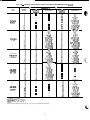
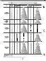
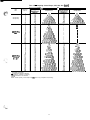
Table 4D - Capacity Control Steps, 225, 250,280
r
UNIT
30GT
225 (60 Hz)
LOAC
%
Displacement
(Awox)
12
2
46
E
1:;
\IG SEQUENCE A
LOADING SEQUENCE B
%
Compressors
*1A’B1
Al ,A2,61
Al ,A2,Bl ,B2
Al ,A2,A3,Bl
,B2
Al ,A2,A3,Bf ,B2,B3
Al ,A2,A3,A4,Bl
,B2,B3
Al.A2.A3.A4.Bl.B2.B3.84
Al*
Al?Bl
Al ,Bl
Al *,A2,Bl
Al ,A2,Bl
Al *,A2,Bl ,B2
Al ,A2,Bl ,B2
Al l ,A2,A3,Bl ,B2
Al ,A2,A3,Bl
,B2
Al *,A2,A3,Bl
,B2,B3
Al ,A2,A3,Bl
,B2,83
Al *,A2,A3,A4,Bl ,B2,B3
Al ,A2,A3,A4,Bl
,B2,B3
Al*,A2,A3,A4,Bl,B2,B3,B4
Al ,A2,A3,A4,Bl
,B4,63,A4
Al*
Al _
Al *,Bl*
Al,Bl*
Al,Bl
Al *,A2,Bl*
Al *,A2,Bl
Al ,A2,Bl
Al *,A2,Bl *,B2
Al ,A2,Bl *,B2
Al ,A2,Bl ,B2
Al *,A2,A3,Bl
*,B2
Al *,A2,A3,Bl
,B2
Al ,A2,A3,Bl
,B2
Al l
,A2,A3,Bl l
,B2,B3
Al ,A2,A3,Bl
*,B2,B3
Al ,A2,A3,Bl
,B2,B3
Al *,A2,A3,A4,Bl
*,B2,B3
Al*,A2,A3,A4,Bl ,B2,83
Al ,A2,A3,A4,Bl
,B2,B3
Al*,A2,A3,A4,Bl*,B2,83,84
Al.A2.A3.A4.Bl*.B2.B3.84
A1’,Ai,A$A4,Bl ,B2,B3,B4
225 (50 Hz)
r
A%
Al ,A2,Bl
Al ,A2,Bl ,B2
Al ,A2,A3,Bl
,B2
Al ,A2,A3,Bl
,B2,B3
Al ,A2,A3,A4,Bl
,B2,B3
Al,A2,A3,A4,Bi,B2,B3,84
Al*
Ali’Bl
Al ,Bl
Al *,A2,Bl
Al ,A2,Bl
At *,A2,Bl ,B2
Al ,A2,Bl ,B2
Al *,A2,A3,Bl ,B2
Al ,A2,A3,Bl
,B2
Al *,A2,A3,Bl ,B2,B3
Al ,A2,A3,Bl
,B2,B3
Al *,A2,A3,A4,Bl
,B2,B3
Al ,A2,A3,A4,Bl
,B2,B3
Al*,A2,A3,A4,Bl ,B2,B3,B4
Al,A2,A3,A4,Bl,B2,B3,84
*Unloaded compressor.
TCompressor unloader, standard.
**Compressor unloader, accessory
TtTwo unloaders, both unloaded.
NOTE: These capacity control steps may vary due to lag compressor sequencing
23
Displacement
Compressors
hwrox)
12
-
A&
Al $1 ,B2
Al ,A2,Bl ,B2
Al ,A2,Bl ,B2,B3
Al ,A2,A3,Bl
,B2,B3
Al ,A2,A3,Bl
,B2,B3,B4
Al,A2,A3,A4,Bl,B2,B3,B4
-
Bl*
Ai&*
Al ‘,Bl
Al ,Bl
Al *,Bl *,B2
Al ,Bl *,B2
Al,Bl,B2
Al *,A2,Bl *,B2
Al *,A2,Bl ,B2
Al ,A2,Bl ,B2
Al *,A2,Bl *,B2,83
Al ,A2,Bl*,B2,83
Al ,A2,Bl ,B2,B3
Al l
,A2,A3,Bl*,B2,B3
Al *,A2,A3,Bl ,B2,83
Al ,A2,A3,Bl
,B2,83
Al *,A2,A3,Bl *,B2,83,84
Al ,A2,A3,Bl*,B2,B3,B4
Al ,A2,A3,Bl ,B2,B3,B4
Al*,A2,A3,A4,Bl*,B2,B3,B4
Al*,A2,A3,A4,Bl,B2,83,B4
At ,A2,A3,A4,Bl
,A2,B3,B4
AL
Al $1 ,B2
Al ,A2,Bl ,B2
Al ,A2,Bl ,B2,83
Al ,A2,A3,Bl
,B2,B3
Al ,A2,A3,Bl
,B2,B3,B4
Al,A2,A3,A4,Bl,B2,B3,B4
-
-
-
Table 4D - Capacity Control Steps, 225, 250,280 (cant)
UNIT
30GT
r
LOAC JG
22
32
250 (60
Hz)
SEQUENCE A
t:
54
57
Compressors
Al*
Bl*
Al% *
Al ,Bl*
Al ,Bl
Al *,A2,81*
Al *,A2,Bl
Al ,A2,Bl
Al *,A2,Bl *,B2
Al ,A2,B1 *,B2
Al ,A2,Bl ,B2
A l *,A2,A3,Bf*,B2
Al *,A2,A3,Bl ,B2
Al ,A2,A3,Bi
,B2
Al*,A2,A3,Bi*,B2,63
Al*,A2,A3,Bl ,B2,B3
Al ,A2,A3,Bl
,B2,B3
Al *,A2,A3,A4,Bl*,B2,83
Al *,A2,A3,A4,Bl ,B2,B3
Al ,A2,A3,A4,Bl
,B2,B3
Al*,A2,A3,A4,Bl*,B2,83,B4
Al*.A2.A3.A4.Bl.B2.63.84
Al ,A2,A3,A4,Bl
,B2,B3&4
Al*B&*
Al,Bl*
Al ,Bl
Al *,A2,Bl*
Al *,A2,Bl
Al ,A2,Bl
Al *,A2,Bl *,B2
Al ,A2,Bl *,B2
Al ,A2,Bl ,B2
Al *,A2,A3,BI *,B2
Al*,A2,A3,Bl ,B2
Al ,A2,A3,Bl
,B2
Al’,A2,A3,Bi*,B2,B3
Al *,A2,A3,Bl ,B2,B3
Al ,A2,A3,Bl
,B2,83
Al*,A2,A3,A4,Bl*,B2,B3
Al *,A2,A3,A4,B1
,B2,B3
Al ,A2,A3,A4,Bl
,B2,B3
Al*,A2,A3,A4,Bl*,B3,B3,64
Ai*,A2,A3,A4,Bl ,B2,B3,B4
Al,A2,A3,A4,Bl,B2,B3,84
A%1
Al ,A2,Bl
Al ,A2,Bl ,B2
Al ,A2,A3,Bl
,B2
Al ,A2,A3,Bl
,B2,B3
Al .A2.A3,A4.B1
.B2.B3
AK31
Al $1 ,B2
Al ,A2,Bl ,B2
Al ,A2,Bl ,B2,B3
Al ,A2,A3,Bl ,B2,83
Al .A2.A3.Bl
.B2,B3.B4
Al ,A2,d3,A4,Bl ,B2,B3,B4
Al!‘Bl
Al ,Bl
“A:*gB;
Al *,A2,Bl ,B2
Al ,A2,Bl ,B2
Al *,A2,A3,Bl
,B2
Al ,A2,A3,Bl
,B2
Al *,A2,A3,Bl ,B2,B3
Al ,A2,A3,Bl
,B2,B3
Al *,A2,A3,A4,Bl
,B2,B3
Al ,A2,A3,A4,Bi
,B2,B3
A1*,A2,A3,A4,Bl ,B2,B3,B4
Al,A2,A3,A4,Bl ,B2,B3,B4
Al*
Al% *
Al ,bl
Al ,Bl
Al*,A2,Bl*
Al *,A2,01
Al ,A2,Bl
Al l ,A2,Bl *,B2
Al ,A2,Bl*,B2
Al ,A2,Bl ,B2
Al *,A2,A3,Bl*,B2
Al *,A2,A3,Bl
,B2
Al ,A2,A3,Bl
,B2
Al*,A2,A3,Bl*,B2,B3
Al ,A2,A3,Bl
*,B2,63
Al ,A2,A3,Bl
,B2,83
Al *,A2,A3,A4,Bl*,B2,B3
Al*,A2,A3,A4,Bl,B2,B3
Al ,A2,A3,A4,Bl
,B2,B3
Al*,A2,A3,A4,Bl*,B2,B3,B4
Al,A2,A3,A4,Bl*,B2,B3,B4
Al,A2,A3,A4,Bl,B2,63,84
l
s7:
:i
96
100
LOAC 4G SEQUENCE B
Compressors
Al*
29
32
l-
*Unloaded compressor.
JCompressor un!oader,
standard
**Compressor unloader, accessory
ttTwo unloaders, both unloaded.
NOTE: These capacity control steps may vary due to lag compressor sequencing.
24
-
Bl”
Al% *
Al ‘,Bl
Al ,Bl
Al *,Bl*,B2
A l , B l “,B2
Al ,Bl ,B2
Al l ,A2,Bl *,B2
Al *,A2,Bl ,B2
Al ,A2,Bl ,B2
Al *,A2,Bl *,B2,B3
Al ,A2,Bl *,B2,B3
Al ,A2,Bl ,B2,B3
Al*,A2,A3,Bl*,B2,B3
Al*,A2,A3,Bl ,B2,B3
Al ,A2,A3,Bl ,B2,83
Al*,A2,A3,Bl *,B2,B3,B4
Al,A2,A3,Bl*,B2,83,84
Al ,A2,A3,Bi
,B2,B3,B4
Al*,A2,A3,A4,Bl*,B2,B3,B4
Al*,A2,A3,A4,Bl,B2,B3,84
Al ,A2,A3,A4,Bl,B2,63,84
Table 4D - Capacity Control Steps, 225, 250, 280 (cant)
1G SEQUENCE A
UNIT
30GT
CONTROL
STEPS
Compressors
Al
250 (50 Hz)
280 (60 Hz)
250 f& Hz),
Al**
250 $;; Hz),
Al**,Bl**
Al ,A2,61
Al ,A2,Bl ,B2
Al ,A2,A3,Bl
,B2
Al ,A2,A3,Bl ,B2,B3
Al ,A2,A3,A4,Bl
,B2,83
Al,A2,A3,A4,Bl,B2,B3,B4
Al”
r
LOADING SEQUENCE B
Compressors
AK1
Al $1 ,B2
Al ,A2,Bi ,B2
Al ,A2,Bl ,B2,B3
Al ,A2,A3,Bl ,B2,B3
Al ,A2,A3,A4,Bl
,B2,83
Al,A2,A3,A4,Bl,B2,B3,84
-
AlA’Bl
Al ,Bl
Al l ,A2,Bl
Al ,A2,Bl
Al *,A2,Bl ,I32
Al ,A2,Bl ,B2
Al*,A2,A3,Bl ,B2
Al ,A2,A3,Bl
,B2
At*,A2,A3,Bl ,B2,B3
Al ,A2,A3,Bl
,B2,B3
Al l ,A2,A3,A4,Bi ,B2,B3
Al ,A2,A3,A4,Bl
,B2,B3
Al*,A2,A3,A4,Bl,B2,83,84
Al,A2,A3,A4,Bl,B2,B3,B4
Al*
Bi*
Al% *
Al ,Bi*
Al ,Bl
Al *,A2,Bl*
Al ‘.A2.B-l
Al ,A2,Bl
Ai *.A2.B1 *,B2
Al ,A2,Bl *,B2
Al ,A2,Bl ,B2
Al *,A2,A3,Bl
*,B2
Al l ,A2,A3,Bl ,B2
Al ,A2,A3,Bl
,B2
Al*,A2,A3,Bl *,B2,B3
Al ,A2,A3,Bi *,B2,B3
Al ,A2,A3,Bl
,B2,83
Al *,A2,A3,A4,Bl
*,B2,B3
Al *,A2,A3,A4,Bl
,B2,83
Al ,A2,A3,A4,Bl
,B2,B3
Ai*,A2,A3,A4,Bl*,B2,B3,B4
Ai,A2,A3,A4,Bl*,B2,B3,B4
Ai,A2,A3,A4,Bl,B2,B3,B4
A&*
Al ‘,Bl
Al ,Bi
Al l ,Bl*,B2
Al ,Bi *,B2
Al ,Bl ,B2
Al*,A2,Bl *,B2
Al l ,A2,Bl ,B2
Al ,A2,Bl ,B2
Al *,A2,Bl *,B2,B3
Al ,A2,Bl *,B2,B3
Al ,A2,Bl ,B2,63
Al*,A2,A3,Bi *,B2,B3
Al*,A2,A3,Bl ,B2,B3
Al ,A2,A3,Bl
,B2,B3
Al *,A2,A3,Bi*,B2,B3,B4
Al ,A2,A3,Bl*,B2,B3,B4
Al ,A2,A3,Bl
,B2,B3,B4
Al*,A2,A3,A4,Bl*,B2,B3,B4
Ai*,A2,A3,A4,Bi,B2,83,B4
Al ,A2,A3,A4,Bi
,B2,B3,B4
*Unloaded compressor.
--/-Compressor unloader, standard.
““Compressor unloader, accessory
ttTwo unloaders, both unloaded
NOTE: These capacity control steps may vary due to lag compressor sequencing
25
-
As the condensing temperature rises, the EXV closes to
maintain the proper suction superheat. Once the EXV has
closed to 39.5% open (300 steps open), a fan stage is added
after 2 minutes.
During start-up, all the condenser fans are started when
the condensing temperature reaches 95 F (35 C) to prevent
excessive discharge pressure during pulldown. See Table 5
for condenser fan sequence of operation.
Head Pressure Control - The microprocessor controls the condenser fans in order to maintain the lowest condensing temperature possible, thus the highest unit efficiency.
Instead of using the conventional head pressure control methods, the fans are controlled by the position of the EXV and
suction superheat.
As the condensing temperature drops, the EXV opens to
maintain the proper suction superheat. Once the EXV is
fully open, if the condensing temperature continues to drop,
the suction superheat begins to rise. Once the suction superheat is greater than 40 F (22.2 C), a fan stage is removed
after 2 minutes,
Table 5 - Condenser Fan Sequence
FAN ARRANGEMENT
30GN040-050
I
FAN NUMBER(S)
FAN CONTACTOR
WI
CONTROLLED BY
1
FC-Al
Compressor Al
2
FC-Bi
Compressor Bl
3
FC-A2
First Stage
Microprocessor
4
FGB2
I
I
30GN060,070
FC-Al
I
Second Stage
MicrODrOceSSOr
I
Compressor Al
Compressor Bi
First Stage
Microprocessor
5 6
30GN080,090
FGB2
Second Stage
Microprocessor
FC-Al
Compressor Al
Compressor Bi
1
FC-Al
Compressor Al
2
FC-81
Compressor Bl
3
4
FC-A2
F&B2
First Stage
Microprocessor
5, 7, 6, 8
FC-AS, FGB3
Second Stage
Compressor
3, 4, 5, 6, 7, a
FC-A2, FC-A3 ,
FGB2, FC-B3
Third Stage
Microprocessor
5 7
FC-Al
Compressor Al
6,
FC-Bl
Compressor Bl
30GNl00,110 (and associated modular units)
. -_-
30GN130-170
(and associated modular units)
WWER
8
FC-A2, FC-A3
30GN190,210
(and associated modular units)
I
*Control
5, 7
I
FC-Al
I
Compressor Al
6. 8
I
FC-Bi
I
Comwessor Bl
3, 9
FC-A2
4, 10
FC-B2
Frist Stage
Microprocessor
1 , 3, 9, 11
2, 4 , 10, 1 2
FC-A2, FGA3
FGB2, FC-B3
Second Stage
Microprocessor
box.
26
Table 5 - Condenser Fan Sequence (cant)
FAN ARRANGEMENT
FAN NUMBER(S)
FAN C~;;jACToR
CONTROLLED BY
7, 8
FC-1
Compressor Al
9, 1 0
FC-4
Compressor 61
5, 6
11, 1 2
FC-2
FC-5
First Stage
Microprocessor
1, 2, 3 , 4
13, 14, 15, 16
FC-3
FC-6
Second Stage
Microprocessor
1, 2, 3, 4, 5, 6
11, 12, f3, 14, 15, 1 6
FC-2, FC-3
FC-5, FC-6
Third Stage
Microprocessor
7, 8, 10
FC-1
Compressor Al
9, 17, 1 8
FC-4
Compressor Bl
5, 6
11, 12, 19
FC-2
FC-5
First Stage
Microprocessor
1, 2, 3, 4, 13,
14, 15, 16, 20
FC-3, FC-6, FC-7
Second Stage
Microprocessor
1 , 2, 3, 4, 5, 6, 11, 12, 13,
14, 15, 16, 19, 2 0
FC-;&F6c;3kF;-5,
-3
-
Third Stage
Microprocessor
7, 8, 1 0
FC-1
Compressor Al
9, 17, 1 8
FC-4
Compressor Bl
FC-2
30GT225
30GT250 (60 Hz)
30GT250 (50 Hz) AND 30GT280
5,
L
/;
/ :‘ i
k.
6
II, 12, 19,20
FC-5
First Stage
Microprocessor
1, 2, 3, 4, 13,
14, 15, 16, 21, 22
FC-3, FC-6, FC-7
Second Stage
Microprocessor
1, 2, 3, 4, 5, 6, 11, 12, 13,
14, 15, 16, 19, 20, 21, 2 2
FC-2, FC-3, FC-4,
FC-5, FC-6, FC-7
Third Stage
Microprocessor
*Control box.
tPower box.
w
saturated suction temperature is below -15 F (-26 C). At
this point, the EXV starts to open and continues to open
gradually to provide a controlled start-up to prevent liquid
flood-back to the compressor.
At shutdown, the pumpout cycle continues until the saturated suction temperature for that circuit is 10” F (5.5” C)
below the saturated suction temperature when pumpout is
initiated, or saturated suction temperature reaches -15 F
(-26 C). At that point, the compressor shuts down and the
EXV continues to move until fully closed.
Pumpout - When the lead compressor in each circuit
is started or stopped, that circuit goes through a pumpout
cycle to purge the cooler and refrigerant suction lines of
refrigerant.
The pumpout cycle starts immediately upon starting the
lead compressor and continues until the saturated suction
temperature is 10” F (5.5” C) below the saturated suction
temperature at start-up, is 10” F (5.5” C) below the cooler
leaving fluid temperature, or reaches a saturated suction temperature of -15 F (-26 C). No pumpout is necessary if the
27
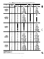
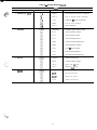
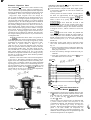
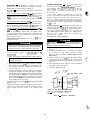
Keypad and Display Module (Also Called HSIO
or LID) - The only function of this module is to allow
The default display is displayed every 2 seconds if there
has been no manual input from the keypad for 10 minutes.
the operator to communicate with the processor. It is used
to enter configurations and set points and to read data, perform tests, and set schedules. This device consists of a keypad with 6 function keys, 5 operative keys, 12 numeric keys
(0 to 9, 0, and -), and an alphanumeric g-character LCD
(liquid crystal display). See Fig+ 3. See Table 6 for
key usage.
To return to automatic display, enter ~~~~
at any
time.
Table 6 - Keypad and Display Module Usage
ACCESSING FUNCTIONS AND SUBFUNCTIONS - See
Tables 6 - 8. Table 7 shows the 6 functions (identified by
name) and the subfunctions (identified by number).
FUNCTION
KEYS
USE
STAT
0
HIST
q
SRVC
0
ElEST
ElCHD
q
STATUS - For displaying diagnostic codes and
current operating information about the machine.
HISTORY - For displaying run time, cycles and
previous alarms.
SERVICE - For entering specific unit configuration information.
TEST - For checking inputs and outputs for
proper operation.
SCHEDULE - For entering occupied/unoccupied
schedules for unit operation
SET POINT - For entering operating set points
and day/time information.
OPERATIVE
KEYS
USE
EXPN
El
EXPAND - For displaying a non-abbreviated expansion of the display
SET
CLEAR - For clearing the screen of all displays
CLA
El
UP ARROW - For returning to previous display
position,
DOWN ARROW - For advancing to next display
position.
ctl
cc l
ENTR
q
A
ENTER - For entering data
KEYPAD OPERATING INSTRUCTIONS (Refer to
Table 9.)
1. White keys on left side of keypad are shown and operated in these instructions according to the following example: keypad entry means
m H press the
q
, then
the white key marked H .
2. The standard display uses abbreviations. Expanded in-
q
formation scrolls through the display whenever
key
is pressed.
3. All functions are made up of a group of subfunctions.
To enter a subfunction, first press subfunction number
desired. Then press the function key in which the subfunction resides. To move within that subfunction, press
Fig. 3 - Keypad and Display Module
SUMMARY DISPLAY - When keypad has not been used
for 10 minutes, display automatically switches to the rotating summary display. This display has 4 parts, listed below, which appear in continuous rotating sequence.
q
the
or m arrow. For example, a mpl enters
the Temperature Information subfunction.
4. At any time, another subfunction may be entered by entering the subfunction number, then the function key.
5. Prior to starting unit, check leaving fluid set point for
correct setting. Refer to Set Point Function section on
page 39.
6. Depending on system configuration, all displays may not
be shown. All displays are shown unless marked with
the following symbol.
*Must be configured.
For additional unit start-up procedures, see separate Installation, Start-Up and Service Instructions supplied with
unit.
DISPLAY
1 EXPANSION
TUE 15:45
TODAY IS TUE, TIME IS 1545 (3:45 PM)
CLOCK ON
UNIT IS ON VIA CLOCK SCHEDULE
COOL 1
NUMBER OF STAGES IS 1
2 ALARMS 1 2 ALARMS DETECTED
I
AUTOMATIC DISPLAY OPERATION/DEFAULT DISPLAY - In this mode, the keypad displays the current time
(24”hour format), current operating modes, cooling capacity stages, and total number of alarms.
MODE X
DOW
K
COOL x
- Day of Week
- Hour(s)
- Minute(s)
28
Table 7 - Functions and Subfunctions
Status
Test
STAT
0
TEST
su6FUNFT’oN
1
2
FUNCTIONS
Schedule
c l
outputs
Automatic
Display
Alarm
Display
Compressors
and Unloaders
Clock Set
;g;faQeratiw)
-
Period 1
4
plWe$Y
-
Period 2
5
Set Points
(Current Operating)
Temperatures
Pressures
Analog
Inputs
outputs
-
-
Period 3
-
Period
Period
Period
Period
Period 8
HOLIDAYS
-
History
SRVC
c
l
Override
3
6
7
8
9
10
II
Service
CHD
ICI
c
Run Time
Log On and
Log Off
Version
(Software)
Factory
Configuration
Field
Configuration
Service
Configuration
-
4
5
6
7
Set Point
HIST
0
l
-
Set Points
(Chiller Fluid)
Reset
Set Points
Demand Limit
Set Points
Date and
Time
-
z
-
-
Starts
Alarm
History
-
-
SET
Table 8 - Accessing Functions and Subfunctions
OPERATION
To access a function, press
subfunction no and function
name key. Display shows subf u n c t i o n @+oup.
To move to other elements,
scroll up or down using arrow
keys. NOTE: These
displays do not show if
control is not configured
for reset.
When the last element in a
subfunction has been displayed, the first element is
repeated.
To move to next subfunction
it is not necessary to use
subfunction number Press
function name key to adVance display through all
subfunctions within a
function and then back
to the first
To move to another function,
either depress function name
key for desired function
(display shows the first
subfunction),
I
I
KEYPAD
ENTRY
I
p--jH
DISPLAY
RESPONSE
I
DESCRIPTION
RESET
Reset Set Points
4
El
CRST2xx
c+ l
CREF2xx
Cooling
Maximum
Reset xx
Cooling
Maximum
Reference xx
Cooling Minimum
Reference xx
Cooling Minimum
Reference xx
CRSTi x x
l-i-l
I
4
cl
CREFlxx
c+l
RESET
Reset Set
c+ l
CRST2xx
(ZtZi:SxxMaxirnurn
SET
c l
DEMAND
Demand Set
Points
TIME
Current Time and
Day of Week
III
SET
Unit Set Points
STAT
III
X ALARMS
Rotating
SET
c l
SET
Access a’ipecif ic subfunction by’using the subfunction number and the
function name kev.
Display
Capacity Stages
29
-
Table 9 - Keypad Directory
STATUS
KEYPAD ENTRY
DISPLAY
1
COMMENT
Refer to Automatic Display Operation on page 28
2 ALARMS
I
X ALARMS
Number of Tripped Alarms
ALARM X
ALARM X
ALARM X
Displays Tripped Alarms
ALARM X
3 MODES
ALARM X
>
X MODES
Number of Modes in Effect
MODE X
MODE X
Displays Mode in Effect
MODE X
4 STAGE
5 SET POINT
6 TEMPERATURE
CCN
EXV
MOP
MODE X
>
STAGE
Capacity
STAGE X
Number of Requested Stages
CAPT X
Percent of Total Capacity
CAPA X
Percent Circuit A Capacity
CAP0 X
Percent Circuit 6 Capacity
LMT X*
Demand Limit Set Point
LOAD X*
Load Limit Set Point
CIRA X
Circuit A Compressor Relay Status
CIRB X
Circuit B Compressor Relay Status
SMZ X
Load/Unload Factor for Compressors
Factor = 1 Unloader Factor = 0 6
SET POINT
Fluid Set Point Information
SP x
Set Point
MSP X
Modified Set Point = Set Point + Reset
TWX
Cooler
TEMPS
Temperature
EWTX
Cooler
Entering
Fluid
Temperature
LWT X
Cooler
Leaving
Fluid
Temperature
SCTA X
Circuit A Saturated Condenser Temperature
SSTA X
Circuit A Saturated Suction Temperature
CTA X
Compressor Al Suction Temperature
SHA X
Circuit A Suction Superheat
LEGEND
- Carrier Comfort Network
- Electronic Expansion Valve
- Maximum Operating Pressure
Staging
Leaving
*Must be configured
j-If a p p l i c a b l e
30
Information
Fluid
Temperature
Information
6;,
Table 9 - Keypad Directory (cant)
STATUS (cant)
SUBFUNCTION
6 TEMPERATURE (cant)
I
KEYPADENTRY
cl 4
qt
cl 4
cl 4
04
7 PRESSURE
8 ANALOG
9 1NPUTS
DISPLAY
COMMENT
SCTB X
Circuit B Saturated Condenser Temperature
SSTB X
Circuit B Saturated Suction Temperature
CTB X
Compressor Bl Suction Temperature
SHB X
Circuit B Suction Superheat
RST X*
Reset Temperature
PRESSURE
Refrigerant System Pressure (psig)
DPA X
Circuit A Discharge Pressure
SPA X
Circuit A Suction Pressure
xxxx
Circuit A Discharge/Suction
OPA X
Circuit A Oil Pressure Differential
DPB X
Circuit B Discharge Pressure
SPB X
Circuit 8 Suction Pressure
xxxx
Circuit B Discharge/Suction
OPB X
Circuit B Oil Pressure Differential
ANALOG
Status of Analog Inputs
REF X
Transducer Supply Voltage
LMT X*
Demand 4-20 mA
RST X*
Reset 4-20 mA Signal
INPUT
Status of Switch Inputs
SPW
Dual Set Point Switch
x*
Signal
DLI X*
Demand Limit Switch 1
DL2 X*
Demand Limit Switch 2
31
Table 9 - Keypad Directory (cant)
STATUS (cant)
SUBFUNCTION
DISPLAY
10 OUTPUTS
COMMENT
OUTPUTS
Status of Outputs
ALMR X
Alarm Relay K3
FRAI X
Fan Relay Kl
FRA2 X
Fan Relay K2
FRBI X
Fan Relay K4
FRB2 X
Fan Relay K5
CHWP X*
Cooler Water Pump Relay K6
ULAI X
Unloader Al t
ULA2 X*
Unloader A2T
ULBI X
Unloader Bl t
ULB2 X*
Unloader B2T
EXVA X
EXVA Percent Open
EXVB X
EXVB Percent Open
HGBA X*
Hot Gas Bypass Relay Circuit A
HGBB X
Hot Gas Bypass Relay Circuit B
MMA X*
Motormaster@
MMB X
Motormaster B Output Percent
A Output Percent
TEST
To use Test function, LOCAL/ENABLE-STOP-CCN switch must be in STOP position To operate a test, scroll to desired test
Then, press m to start test. Press m to stop test.
SUBFUNCTION
1 OUTPUTS
KEYPAD ENTRY
COMMENT
DISPLAY
OUTPUTS
Test Outputs
8 8 8.8.8 8.8.8
Display Check
ALMR X
Energize Alarm Relay K3
FRAI X
Energize Fan Relay Al Kl
FRA2 X
Energize Fan Relay A2 K2
FRBl X
Energize Fan Relay Bi K4
FRl32 X
Energize Fan Relay 82 K5
CHWP X*
Energize Cooler Water Pump K6
EXVA X
Enter Desired EXVA Position
EXVB X
Enter Desired EXVB Position
HGBRA X*
Energize Hot Gas Bypass Relay A
HGBRB X*
Energize Hot Gas 8ypass Relay B
MMA X*
Enter Desired Motormaster@
MMB X*
Enter Desired Motormaster B Output Signal
32
A Output Signal
Table 9 - Keypad Directory (cant)
TEST (cant)
During compressor test, compressors start and run for
10 seconds. Compressor service valves and liquid line
valves must be open. Energize crankcase heaters 24 hours
prior to performing compressor tests.
KEYPAD ENTRY
SUBFUNCTION
DISPLAY
2 COMPRESSORS AND
UNLOADERS
COMMENT
COMP
Compressor and Unloader Test
CPA1 X
Test Compressor Al
CPA2 X*
Test Compressor A2T
CPA3 X*
Test Compressor A3t
CPA4 X*
Test Compressor A4t
CPBl X
Test Compressor Bl
CPB2
x*
Test Compressor B2t
CPB3 X*
Test Compressor B3T
CPB4 X*
Test Compressor B4T
ULAl X
Energize Unloader Al T
ULA2 X*
Energize Unloader A2T
ULBl X
Energize Unloader Bl t
ULB2 X*
Energize Unloader B2t
SCHEDULE
The Schedule function key CHD is used to configure the occupancy schedule The clock select subfunction can be used for
El
unoccupied shutdown or unoccupied setback depending on the cooling set point control configuration. The Schedule function
described is for clock 1, which is the internal clock. Password required for all subfunctions except override.
SUBFUNCTION
1
KEYPAD ENTRY
DISPLAY
I
COMMENT
I
OVRD X
Number of Override Hrs (0 - 4 Hrs)
ppii-j
OVRD 3
Extended
/qzq
CLOCK XX
Type of Clock Control
0 = No Clock, 1 = Clock 1 (Internal)
1 OVERRIDE
I
For example, to extend current occupied mode for 3 hrs, press:
2 CLOCK SELECT
~~”
MOP
LEGEND
- Carrier Comfort Network
- Electronic Expansion Valve
- Maximum Operating Pressure
*Must be configured
tlf a p p l i c a b l e .
33
Occupied
Time
Table 9 - Keypad Directory
SCHEDULE (cant)
DISPLAY
To toggle between inputs (Yes/No) Press:
COMMENT
PERIOD 1
Period 1 Time Schedule
OCC HH.MM
Occupied
UN0 HH.MM
Unoccupied
MON X
Monday Flag
TUE X
Tuesday
WED x
Wednesday Flag
THU X
Thursday Flag
FRl X
Friday
SAT X
Saturday
SUN X
Sunday
Flag
HOL X
Holiday
Flag
5 PERIOD 3 . . . 9 PERIOD 7
Flag
Flag
Flag
S c h e d u l e
1 MH
1 P e r i o . dm3 H
. ( . ~~$~
. P ey r ’ i o d
7
~~
( P e r i o d1PERIOD
8
T8 i m e
10 PERIOD 8
Time
Fi Fi
1 P e r i o d1PERIOD
/qH
2
T2 i m e
4 PERIOD 2
Time
11 HOLIDAYS
T i m e
S c h e d u l e
S c h e d u l e
HOLIDAYS
Define Calendar Holidays
DAT MM.DD
Holiday Date 1
New = Unassigned Holiday Date
DAT MM.DD
q
For example: To enter July 4th holiday press: 07 04 01
operation, refer to Schedule Function section on page 45.
NN
Holiday Date 30
. Display shows Jul 04 For further information on the Schedule function and its
SERVICE
To view and modify configurations, the password must be entered under the log on subfunction.
SUBFUNCTION
1 LOG ON AND LOG OFF
KEYPAD ENTRY
DISPLAY
r;lH
LOG ON
( m
ILoggedOn
mmma
Enter Password/Disable Password Protection
(LOGGEDON
At this time, configurations may be modified. When finished viewing and/or modifying
configur
rtions, log out as follows:
LOG OFF
Disable Password Protection
0
EXIT LOG
Logged Off/Enable Password Protection
p-&q
VERSION
Software
xxxxxxxx
Version No. of Software (CESRXX)
+
0
EHTR
2 VERSION
COMMENT
c4 l
X
+
0
See legend on page 30
34
Language
Information
Options
Table 9 - Keypad Directory (cant)
SERVICE (cord)
The next 3 subfunctions provide the ability to modify configurations Refer to separate Installation, Start-Up, and Service Instructions
supplied with unit for further information on changing configurations.
To change a configuration, enter the new configuration and press
4 while on the correct configuration.
F.-’
SUBFUNCTiON
3 FACTORY
CONFIGURATION
Clt
4 FIELD
CONFIGURATION
Clt
ct
ctt
[It
cl
ct l
0t
qt
0t
att
Clt
clt
cl
qt
clt
c+ l
Cl+
Clt
5 SERVICE
CONFIGURATION
I’ i. j,
Fc,s;B,:
DISPLAY
KEYPAD ENTRY
p-&q
clt
ct l
Clt
ct l
ct l
ct l
c+ l
qt
clt
COMMENT
FACT CFG
Factory Configuration Codes
xxxxxxxx
Configuration Code 1
xxxxxxxx
Configuration
Code
2
xxxxxxxx
Configuration
Code
3
xxxxxxxx
Configuration
Code
4
xxxxxxxx
Configuration
Code
5
xxxxxxxx
Configuration
Code
6
FLD CFG
Adjustable
EN0 X
CCN Element Address
BUS X
CCN Bus Number
BAUD X
CCN Baud Rate
FLUID X
Cooler Fluid Select
UNITS X
Display Unit Select
LANG X
Display
NULA X
No Circuit A Unloaders
NULB X
No. Circuit B Unloaders
HGB X
Hot Gas Bypass Select
SEQT X
Loading
SEQF X
Lead/Lag
OPS
Oil Pressure Switch Select
x
Field
Configuration
Language
Sequence
Select
Select
Sequence
Select
HEADM X
Head Pressure Control Method
MM X
Motormaster@
CSPTYP X
Cooling Set Point Control Select
CRTYP X
Cooling Reset Control Select
ERTYP X
External Reset Sensor Select
LSTYP X
Demand Limit Control Select
RAMP X
Ramp Load Select
LOCK X
Cooler Pump Interlock Select
CPC
Cooler Pump Control Select
x
Select
SRV CFG
Service Configurations
xxxxxxxx
Configuration
Code
7
xxxxxxxx
Configuration
Code
8
REFRIG X
Refrigerant
TDTYP X
Pressure Transducer Select
OPS
Oil Transducer Set Point
x
LPS x
Low Pressure Set Point
FANTYP X
Fan Staging Select
SH X
EXV Superheat Set Point
MOP X
EXV MOP Set Point
35
Table 9 - Keypad Directory (cant)
r;lm
1 RUN TIME
I
COMMENT
RUN TIME
Run Time lnformation
+
0
HR X
Total Hrs Unit Has a Comp Operating
4
cl
HRA X
Circuit A Run Time
cb l
HRB X
Circuit B Run Time
STARTS
Starts
c+ l
CY x
Cycles from Stage 0 to Stage 1
c+ l
CYA X
Circuit A Starts
c+ l
CYB X
Circuit B Starts
1 2 1lHlST1
2 STARTS
3 ALARM HISTORY
DISPLAY
KEYPAD ENTRY
SUBFUNCTION
I 3 I lH4
1ALRMHIST
Information
1Last 5 Alarms
ALARM X
ALARM X
ALARM X
Alarm Description
J
>
ALARM X
ALARM X
SET POINT
To read a set point, go to proper subfunction and read desired set point To c h a n g e a set point, enter new set point value, t h e n press
LOCAL/ENABLE-STOP-CCN switch must be in LOCAL or STOP position,
COMMENT
DISPLAY
SUBFUNCTION
KEYPAD ENTRY
1 SET POINTS
SET POINT
Jnit Set Point
CSPl
x
Chiller Fluid Set Point 1
CSP2
x
Chiller
cl
ENTR
Fluid Set Point 2
HSPA X
Head
HSPB X
Head Pressure Set Point Circuit B
CRAMP X
Pulldown
RESET
Reset Set Points
CRST2 X*
Cooling Max Reset
CREF2 X*
Max Reset Occurs at X mA or Degree
CRSTI
Cooling
Pressure Set Point Circuit A
Limit
t
2 RESET SET POINTS
3 DEMAND SET POINTS
4 DATE AND TIME
X*
Minimum
Reset
CREFI X*
Min Reset Occurs at X mA or Degree
DEMAND
Demand Set Points
DLSl X*
Demand Switch 1 Set Point
DLS2 X*
Demand Switch 2 Set Point
DMAX X*
4-20 mA
RMAX X*
Max Demand Limit Occurs at X mA
DMIN
X*
4-20
RMIN
X*
Minimum Demand Limit Occurs at X mA
Maximum Demand Limit
mA
Minimum Demand Limit
SHED X”
CCN Loadshed
DATE.TIME
Date, Time and Day of Week
DAY HR.MIN
Day 1 = Mon, 2 = Tues
Hours are displayed in 24-hr
MM.DD YR
Month.Day.Year.
When entering date, enter a decimal
point between entries. Each entry must be two numbers.
36
Amount
7 = Sun
time. Decimal point serves as colon.
i
Table 10 - Operationat and Mode Display Codes
The operating modes are displayed by name or code number, to indicate the operating status of the unit at a given
time. The modes are:
STATUS FUNCTION - This function shows the rotating
display, current status of alarm (diagnostic) codes, capacity
stages, operating modes, chilled water set point, all measured system temperatures and pressures, superheat values,
pressure switch positions, analog inputs, and switch inputs.
These subfunctions are defined on pages 37 and 38.
m
( R oFi
tating
CODE
DESCRlPTlON
Unit is off. LOCAL/ENABLE-STOP-CCN switch is
LOCAL OFF in OFF position, or LOCAL/ENABLE-STOP-CCN
switch may be in LOCAL position with external ON/
OFF switch in OFF position
Unit is off due to CCN network command. LOCAL/
CCN OFF
I ENABLE-STOP-CCN switch is in CCN position.
Unit is off due to internal clock schedule. LOCAL/
CLOCK OFF ENABLE-STOP-CCN switch is in LOCAL position.
Unit is on. LOCAL/ENABLE-STOP-CCN switch is
LOCAL ON
in LOCAL position If external ON/OFF switch is used,
it will be in ON bosition.
Unit is on due to CCN command LOCAUENABLECCN ON
STOP-CCN switch is in CCN position.
Unit is on due to internal clock schedule or occuCLOCK ON
pied override function. LOCALIENABLE-STOPCCN switch is in LOCAL position.
Dual set point is in effect In this mode, unit continues to run in unoccupied condition, but leaving waMODE 7
ter set point is automatically increased to a higher
level (CSP2 set Point is in SET function)
Temperature reset is in effect. In this mode, unit is
using temperature reset to adjust leaving water set
point upward, and unit is currently controlling to the
MODE 8
modified set point. The set point can be modified
based on return water, outdoor-air temperature or
space temperature
Demand limit is in effect. This indicates that capacity of unit is being limited by demand limit conMODE 9
trol option Because of this limitation, unit may
not be able to produce the desired leaving water
temperature
Load limit is in effect. This indicates that capacity of
a system of units is being limited by a CCN loadMODE 10
shed command Due to this limitation, unit may
not be able to produce the desired leaving water
temperature.
MODE II
Not aoalicable.
Ramp load (pulldown) limiting is in effect. In this mode,
the r&e at which leaving water temperature is dropped
is limited to a predetermined value to prevent comMODE 12
pressor overloading, See CRAMP set point in the
S E T f u n c t i o n i n T a b l e 9 T h e pulldown
limit can be
modified, if desired, to any rate from 2 F to 2 F
( lo to lo Q/minute
Timed override is in effect This is a 1 to 4 hour
temporary override of the programmed schedule,
MODE 13
forcing unit to occupied mode Override can be implemented with unit under LOCAL or CCN control
Override expires after each use
Low cooler suction protection is in effect In this mode,
circuit capacity is not allowed to increase if cooler
saturated suction temperature is 20” F (11” C) for
’ water or 30” F (16” C) for brine or more below leavMODE 14
ing fluid temperature, and saturated suction temperature is less than 32 F (0’ C). If these conditions
persist beyond 10 minutes, circuit is shut down and
fault code 44 or 45 is displayed.
Display)
(Alarms)
m
Fi - Alarms are messages that one or more
faults have been detected. Each fault is assigned a code number which is reported with the alarm. See Table 10 for code
definitions. The codes indicate failures that cause the unit
to shut down, terminate an option (such as reset) or result
in the use of a default value as set point.
Up to 5 alarm codes can be stored at once. To view them
in sequence, press mm to enter the alarm displays
and then press
q
q
I
to move to the individual alarm dis-
plays. Press
after a code has been displayed. The meaning of the code scrolls across the screen. See Example 1
Example 1 - Reading Alarm Codes
KEYPAD
ENTRY
DISPLAY
RESPONSE
‘MvoEo;2;;5
0 STAGES
2 ALARMS
2 ALARMS
2 alarms detected
+
cl
EXPH
0
ALARM 9
First alarm code
COOLER LEAVING
FLUID THERMISTOR
FAILURE
Explanation of alarm code
4
Ll
EXPN
0
ALARM 42
Second alarm code Cooler
freeze protection
COOLER FREEZE
PROTECTION
Explanation of alarm code
p-jq
I
COMMENTS
Keypad has not been used for
at least 10 minutes. Alternating
summary display appears on
screen
1
I
When a diagnostic (alarm) code is stored in the display
and the machine automatically resets, the code is deleted.
Codes for safeties which do not automatically reset are not
deleted until the problem is corrected and the machine is
switched to STOP, then back to LOCAL/ENABLE or CCN.
1
mbi (Modes) - The operating mode codes are displayed to indicate the operating status of the unit at a given
time. See Table 10.
I
CCN - CarrierComfort
Network
To enter the MODES subfunction, depress MFI and
the
key to determine if more than one mode applies. See Example 2 to read current mode with expansion.
use
37
q
Example 2 - Reading Current Operating Modes
KEYPAD
DISPLAY
ENTRY I RESPONSE I
q
COMMENTS
TUE 15:45
LOCAL ON
COOL 1
0 ALARMS
Keypad has not been used for at
least 10 minutes Rotating summary
display appears on screen
2 MODES
There are 2 modes currently in effect
c4 l
LOCAL ON
Unit is on by chiller on/off switch
c+ l
MODE 8
Temperature reset is in effect
p-lH
m H (Analog Inputs) - This subfunction displays
analog inputs, if any. Enter m Fi , then use the
. The
transducer supply voltage, 4-20 mA reset signal can be displayed. This is useful for problem diagnosis prior to using
the test function.
m
( I bi
n p u t s ) - This subfunction displays status
(ON/OFF) of input switch where applicable. Status of dual
set point switch, and demand limit switches 1 and 2 can be
displayed. This is useful for problem diagnosis prior to using the test function.
~~ (Outputs) - This function displays ON/OFF status of alarm relay, all fan relays, and chilled water pump
relay. It also displays ON/OFF status of compressor unloaders (if used). The position of each EXV (in percent open)
can be displayed.
TEST FUNCTION - The test function operates the diagnostic program. To initiate test function, the LOCAL/
ENABLE-STOP-CCN switch must be in STOP position.
To reach a particular test, enter its subfunction number,
then scroll to desired test by pressing the ( key. Press
l-ii 1;; ;1 (Stage) - This subfunction displays the capacity stage number. See Tables 4A-4D for compressor loading sequence. To enter the STAGE subfunction, press
q
p--&q
and use the
to display the stage number.
Additional m provides the following information:
Percent of total unit capacity being utilized.
Percent of each circuit capacity being utilized.
Demand limit set point in effect (can be any value between 0% and 100%).
Load limit set point in effect. This is a CCN function for
controlling operation of multiple units between 0% and
100% of total capacity of all units combined.
Status of each compressor relay. When a compressor is
on, the number of that compressor is displayed. If a compressor is off, a 0 is displayed. For example: In a given
circuit, if compressors 1 and 3 are running, and 2 and 4
are not running, 0301 is displayed for that circuit.
Load/Unload factor for compressors. This factor is an indication of when a step of capacity is added or subtracted. Its value can range from slightly less than -1 .O
to slightly more than + 1 .O. When load/unload factor
reaches + 1.0, a compressor is added. When the load/
unload factor reaches -1 .O, a compressor is subtracted.
If compressor unloaders are used, at -.6 a compressor is
unloaded and at + .6, a compressor is loaded up.
q
the q
B to start a test. Press
or
q
or H to terminate or
exit a test. Pressing
key after a test has started advances system to next test, whether current test is operating
or has timed out, Once in the next step, you may start
test by pressing H or advance past it by pressing I)I .
While the unit is in test, you may leave test function and
access another display or function by pressing appropriate
keys. However, a component that is operating when another function is accessed remains operating. You must
re-enter test function and press the ) key to shut down
the component. Components with a timed operating limit
time out normally even if another function is accessed.
Keypad entry riF[
allows the operator to make the
following checks by using m :
LID display check. Propezisplay is 8.8.8.8.8.8.8.8 .
Operation of remote alarm.
Operation of condenser fans.
Operation of chilled water pump.
Operation of EXVs. To drive EXV fully open, enter
mF[ (Set Point) - This subfunction displays leaving
water temperature and leaving chilled water set point. If
unit is programmed for dual set point, the chilled water set
point currently in effect (either occupied or unoccupied) is
displayed. If reset is in effect, the unit operates to the modified chilled water set point. This means the leaving water
temperature may not equal the chilled water set point The
modified chilled water set point can also be displayed in the
Status function. To enter the set point subfunction, de-
m m m (100% open). To drive EXV fully closed, enter u (0% open).
c
Keypad entry. -mH Iaccesses the compressor and
compressor unloader operational tests.
q
press mb[ and use the
to display modified leaving
chilled water set point followed by leaving water set point
and actual cooler leaving fluid temperature.
During compressor operational tests, compressor starts
and runs for 10 seconds. Compressor service valves must
be open. Energize crankcase heaters 24 hours prior to
performing compressor tests.
(Temperature)
F[
F[
- The temperature subfunction displays the readings at temperature sensing thermistors.
Since test function checks only certain outputs, it is good
practice to also check all inputs and outputs accessible
through the status function. These are located at F\ F[ ,
To read a temperature, enter Fi Fi , then scroll to desired temperature using the m key. See Table 9 for the
order of readouts.
m H, and mm (see Table 9). If keypad is not used
for 10 minutes, unit automatically leaves test function and
resumes rotating display. See Example 3.
flH (Pressure) - This subfunction displays suction,
discharge and net oil pressure at lead compressor of each
circuit of unit.
38
b. The next value displayed depends on how the schedule function has been programmed. (See pages 4547.) If dual set point has been selected, the next set
Example 3 - Using Test Function
KEYPAD
DISPLAY
ENTRY I RESPONSE
COMP
Factory/field test of compressors
subfunction of test function
CPA 1 OFF
Circuit A, Compressor 1A test
CPA 1 ON
Pressing ENTR starts the test:
when the compressor should be running
the display shows CPA1 on
If the test is allowed to time out (10 seconds) the display will show CPA1 off
Pressing the down arrow key advances
the system to Circuit A, compressor 2 test
CPA 1 OFF
cl+
COMMENTS
CPA 2 OFF
point after m has been pressed is the unoccupied
chilled water set point. If single set point or inactive
schedule has been selected in the schedule function,
q
then when
is pressed, the display shows the
modified chilled water set point.
c. The final value displayed when the
is pressed
is the cooling ramp loading rate. This is the maximum rate at which the leaving chilled water is allowed to drop, and can be field set from 0.2 to 2.0 F
(. 11” to 1.1” C)/minute. This value is not displayed
unless the function is enabled (see Adjustable Field
Configurations on page 45).
Reading and Channinrr Set Points - Example 4 shows how
to read and change the chilled water set point. Other set
points can be changed by following the same procedure.
Refer to Table 9 for the sequence of display of set points in
each subfunction.
q
NOTE: Once a compressor has been run using the EST function, it
E l
is not allowed to run again for 30 seconds.
HISTORY FUNCTION - Keystrokes mb]
and sub-
sequent [ keystrokes display total unit run time and total
run time for each circuit.
.
Keystrokes m m and subsequent m keystrokes display total unit starts and the total starts for each circuit.
keystrokes disKeystrokes Fi b[ and subsequent
play the last 5 alarms along with a description of each alarm.
Example 4 - Reading and Changing
Chilled Water Set Point
q
KEYPAD
ENTRY
SET POINT FUNCTION - Set points are entered through
the keypad. Set points can be changed within the upper and
lower limits, which are fixed. The ranges are listed
below.
Chilled Water Set Point
Water:
38 to 70 F (3.3 to 21 C)
Brine:
15 to 70 F (-9.4 to 21 C)
DISPLAY
RESPONSE
COMMENTS
SET POINT
System set points
CSPl 44.0
Present occupied chilled water
set point is 44 0 F
CSPI 420
CSP2 44.0
CSP2 50.0
Pulldown Set Point
0.2 to 2.0 F (0.11 to 1.1 C)/min.
RESET
Reset Set Points
Maximum Reset Range:
0” to 20” F (0” to 11” C)
Maximum Reset Reference Range:
Return Fluid Reset 0” to 20” F
(0” to 11” C)
External Temperature Reset 20 to 125 F
(-6.6 to 51.6 C)
External Signal Reset 4 to 20 mA
Minimum Reset Reference Range:
Return Fluid Reset 0” to 20” F
(0” to 11” C)
External Temperature Reset 20 to 125 F
(-6.6 to 51.6 C)
External Signal Reset 4 to 20 mA
~~~~~~~h~!$w~cupied
chilled water set point is 42 0 F
Present unoccupied chilled water
set point is 44.0 F
Press the Fi
D i ri
s F[
p l a y
shows new unoccupied chilled
water set point is 50.0 F
Displays the maximum reset and
minimum reset set points The
minimum and maximum reference
reset set points can also be
displayed.
These set points are not
accessible when reset type has
been configured for NONE in
the service function
Temperature Reset Based on Return Water TemDerature The control system is capable of providing leaving water
temperature reset based on return water temperature. Because the temperature difference between leaving water temperature and return water temperature is a measure of the
building load, return water temperature reset is essentially
an average building load reset method.
Under normal operation, the chiller maintairis a constant
leaving water temperature approximately equal to chilled
water set point. As building load drops from 100% down to
O%, entering cooler water temperature drops in proportion
to load. Thus, temperature drop across the cooler drops from
a typical 10 F (5.5 C) at full load to a theoretical 0” F (0” C)
at no load. See Fig. 4.
At partial load, leaving chilled water temperature may be
lower than required. If this is allowed to increase (reset),
the efficiency of the chiller increases. Amount of reset can
be defined as a function of cooler temperature drop, as shown
in Fig. 4. This is a simple linear function that requires 4
pieces of input data for the set function:
Demand Limit Set Points
Switch Input:
Step 1 - 0 to 100% Capacity Reduction
Step 2 - 0 to 100% Capacity Reduction
External Signal:
Maximum Demand Limit 4 to 20 mA
Minimum Demand Limit 4 to 20 mA
Set points are grouped in subfunctions as follows:
Displays
m
Fl chiller water and cooling ramp set points.
a. The first value shown is the occupied chilled water
set point.
39
Example 5 - Using Return Water
Temperature Reset
I. Maximum Reset Amount (CRST2) - allowable range
0” to 20” F (0” to 11” C). This is maximum amount leaving chilled water set point is to be increased.
2. Maximum Reset Reference (CREF2) - allowable range
0” to 20” F (0” to 11” C). This is the cooler temperature
drop at which reset reaches its maximum value.
3. Minimum Reset Amount (CRSTl) - allowable range
0” to 20” F (0” to 1 I” C). This is minimum amount leaving chilled water set point is to be increased when reset
is initiated.
4. Minimum Reset Reference (CREFl) - allowable range
0” to 20” F (0” to 11” C). This is the cooler temperature
drop at which reset is at its minimum value. (Reset begins here .)
NOTE: Reset set points are not accessible unless the reset
function is enabled first. This is done as a field configuration. Select one of the 3 choices for type of reset: Return
Fluid Reset, External Temperature Reset, or 4-20 mA External Signal (with a loop isolator) Reset.
If dual set point control is enabled (see Field Wiring section on page 7 1), the amount of reset is applied to whichever set point is in effect at the time.
Example 5 demonstrates how to activate reset. Example
6 demonstrates how to change the type of reset. Assume
that reset is to be based on return water temperature, the
desired reset range is to be 2” to 10” F (1” to 5.5” C) and
full load is a 10” F (5.5” C) drop across the cooler. See
Fig. 4.
Activating reset based on external temperature or
4-20 mA signal is done the same way, except the reference
set point range is 20” to 125” F (-6.6” to 5 1.6” C), or 4 to
20 mA depending on which method was selected at the field
configuration step.
f73c=)
-- /
KEYPAD
ENTRY
DISPLAY
RESPONSE
COMMENTS
FLD CFG
Field configuration
subfunction of
service function
CSPTYP X
Scroll past single/dual
CRTYP 1
Display shows no reset
type has been selected
Return water temperature
is selected and activated
SET POINT
System set points
CRTYP 0
CPSl 45 6
Present occupied chilled
water set point
Enter new chilled water
set point
RESET
Reset set points
CRST2 0 0
F;li;g
0
CRST2 10 0
Cooling maximum
is 10 F
Cooling maximum
reference is 0” F
Cooling maximum
reference is 1 F
Cooling minimum
is 0” F
Cooling minimum
is 2 F
Cooling minimum
reference is 0” F
Cooling minimum
reference is 8 F
CPSl 44.0
CREF2 0.0
CREF2 1.0
CRSTI
0 0
CRSTI 2.0
CREFl 0.0
CREFl 8 0
maximum reset
reset
reset
reset
reset
reset
reset
reset
35.3
IO
9
18
8
16
7
MIN
RESET
REFERENCE
100
(CREF I ) q 13
80
60
0
2
3
4
5
6
7
RESET REFERENCE TEMPERATURE (COOLER EWT-LWT)
Fig. 4 - Cooling Return W a t e r Reset
40
8
9
IO
Example 6 - Changing Reset Type
To change type of reset, first log on as shown in
Table 11. Also refer to Set Point Function section, page 39,
for information on entering reset set points using reset
feature.
Temperature Reset Based on External Temperature - If desired, temperature reset can be based on an external temperature, such as space or outdoor-air temperature. This requires a thermistor (TlO, Part No. 30GB660002) located in
the space or outdoor air and wired to terminals as follows
(also see Field Wiring section on page 71):
4 in/4
out
KEYPAD
ENTRY
Module - 57-15 and J7-16.
At the field configuration step, select external tempera-
q
DISPLAY
RESPONSE
FLD CFG
ture reset by entering
when CRTYP 0 appears. Then
enter set points as described previously in Example 5. See
Fig. 5.
CSPTYP 0
CRTYP 0
Temperature Reset Based on 4-20 mA Signal- If desired,
temperature reset can be based on a 4-20 mA signal. For
proper connections, refer to Field Wiring section on page
71 and Fig. 6.
At the field configuration step, select 4-20 mA reset by
entering
when CRTYP 0 appears. Then enter set points
as described previously in Example 5. See Fig. 7,
CRTYP 1
CRTYP 2
q
CRTYP 3
Demand Limit, 2-Stage Switch Control - This control has
been designed to accept demand limit signals from a building load shedding control. The demand limit function provides for 2 capacity steps. The keypad is used to set the 2
demand limit set points, which range from 100 to 0% of
capacity. Capacity steps are controlled by 2 field-supplied
relay contacts connected to the designated chiller terminals.
(See Field Wiring section on page 7 1 and Fig. 6.)
CRTYP 0
10 Y-
8?-
18
16
8
6
2-
I O-
RESET REFERENCE
TEMPERATURE
(OUTDOOR
AIR 1OR SPACE TEMP
Fig. 5 - Cooling External Temperature Reset
41
COMMENTS
Field configuration
subfunction of
service function
Scroll past single cooling
set point
No reset has been
selected
Return water temperature
reset is selected and
activated
Reset type is changed to
space or outdoor-air
temperature reset and
activated
Reset type is changed to
4-20 mA signal reset
and activated
Reset is deactivated
n
P O I N T NUMBER OF
FIRST
CHANNEL
Q
PWR
4 nw/4 OUJJU
__-----a
A
B d
I-
--
--e-------1-
c
---mm-
D
EKE
LIMIT
(ALARM
(MODE
__----
Idn AOt
’
=
RET
z
DO+
“1
rAO+
__----.
_------
CODE 312
H
4
5
I
---se
---
91
----
___---c---
- - - - - _- - - - -- - ‘-+p-------(MODE
LEGEND
C O M M - Communications Bus
PWR
- Power
- Switch
SW
NOTE: For specific connection points,
see Fig. 24 - 29.
71
----
----__e-
--
f
RFt!EF
(ALARM COOE 21) 301
(MODE El
__----
__----a-
LB---------
Fig 6 - 4 IN/4 OUT Options Module Wiring for Reset, Demand Limit, an! Dual Set Point
To use Demand Limit, first enable loadshed, then enter
demand limit set points. See Example 7A. Closing the first
stage demand limit contact puts unit on the first demand
limit level, that is, the unit does not exceed the percentage
of capacity entered as demand limit stage 1. Closing contacts on second-stage demand limit relay prevents unit from
exceeding capacity entered as demand limit stage 2. The
demand limit stage that is set to the lowest demand takes
priority if both demand limit inputs are closed.
The demand limit function must be enabled in order to
function and may be turned off when its operation is not
desired. The demand limit relays can, in off condition, remain connected without affecting machine operation.
-Demand Limit, 4-20 mA Signal - The controls can also
accept a 4-20 mA signal for load shedding. Input for the
signal are terminals shown below:
Table 11 - Service Functions
To view and modify configurations, the password must
be entered under the log on subfunction.
SUBFUNCTION I
KEY FAD
ENTRY
DISPLAY
PASSWORD
COMMENT
Enter Password/
Disable
Password
LOGGED ON Logged On
NOTE: Configurations may be modified at this time. When
finished viewing and/or modifying configurations, log out
as follows:
LOGGED ON
LOG OFF
Disable
Password
Protection
EXIT
Logged Off/
Enable
Password
Protection
LOG
VERSION
Software
Information
xxxxxxxx
Version No
of Software
X
Language
Externally powered (loop isolator required)
Positive lead to 57-5 - 4 In/4 Out Module
Negative lead to 57-6 - 4 In/4 Out Module
Internally powered
Positive lead to J7-6 - 4 In/4 Out Module
Negative lead to 57-7 - 4 In/4 Out Module
See Field Wiring section on page 71 and Fig. 6.
At field configuration step, select 4-20 mA loadshed by
entering
when the LSTYP 0 display appears. See
Example 7B. Then enter set points as follows. In this example, set points are coordinates of the demand limit curve
shown in Fig. 8.
q
Options
42
16
8
6
0
0
2
4
6
8
12
IO
RESET REFERENCE SIGNAL
14
16
18
20
(4 - 2 0 M A I N P U T )
Fig. 7 - 4-20 mA Cooling Temperature Reset
Example 7B - Using Demand Limit (4-20 mA)
(First Log On As Shown in Table 11)
Example 7A - Using Demand Limit
(First Log On as Shown in Table 11)
KEYPAD
ENTRY
DISPLAY
RESPONSE
COMMENTS
ERTYP 0
Field configuration subfunction of service function
Scroll past other elements
in the subfunction
LSTYP 0
Loadshed
LSTYP 1
DLSl 100
Loadshed
is now enabled
for 2-stage switch control
Demand Limit set points
subfunction of set point
function
Loadshed
1 currently set
at 100%
DLSl 60
Loadshed
reset to 60%
DLS2 100
Loadshed
at 100%
2 currently set
DLS2 40
Loadshed
2 reset to 40%
FLD CFG
DEMAND
DISPLAY
RESPONSE
ppiq
FLD CFG
t
0
ERTYP 0
Field configuration subfunction
of service function
Scroll past other elements in
the subfunction
LSTYP 0
Loadshed
LSTYP 2
Loadshed
is now enabled
for 4-20 mA signal control
DEMAND
Demand Limit set points
DMAX 100
Maximum demand limit is 100%
DMAX 90
Maximum demand limit is 90%
Cl
LSTYP 1
Field configuration subfunction of servicefunction
Scroll past other elements
in the subfunction
Loadshed
is enabled for
2-stage switch control
LSTYP 0
Loadshed
I
is now disabled
NOTE: Select 3 for Carrier comfort Network (CCN) load limiting
Select 4 for CCN demand limiting.
43
COMMENTS
is not enabled
RMAX 15
Maximum
reference
Maximum
reference
DMIN
0
Minimum demand limit is 0%
DMIN
20
Minimum demand limit is 20%
RMIN
4
RMlN
6
RMAX 20
COMMENTS
FLD CFG
ERTYP 0
DISPLAY
RESPONSE
qMH‘nENTR
is not enabled
To Disable Demand Limit:
KEYPAD
ENTRY
KEYPAD
ENTRY
demand limit
is 20 mA
demand limit
is 15 mA
Minimum demand limit
reference is 4 mA
Minimum demand limit
reference is 6 mA
M A X D E M A N D KIMAX) = 90
DEMAND LlMlT
SIGNAL (4-20 MA INPUT)
Fig. 8 - 4-20 mA Demand Limiting
Logging On/Longing Off - The service function is password protected. Therefore, to gain entry to this function,
Reading and Changing Time Displav - Time is entered
and displayed in 24-hour time. The day of the week is entered as a number.
1 = Mon, 2 = Tue, 7 = Sun, etc.
this password must be entered. Pressing mlrim m
allows the technician to view, change or enter configuration codes. To log off, perform the following keystrokes:
m biF]H ~The service function is once again password protected.
m Kev is used as the colon when entering time. See Example 8.
I
Example 8 - Setting Time of Day and
Day of Week
KEYPAD
ENTRY
DISPLAY
RESPONSE
TIME
MON 1600
TUE 13 05
JAN 01 90
APR 15 90
Software Information - Fi F/VI displays the version
number of the software that resides in the processor mod-
COMMENTS
ule. Press m a second time to display the language options that are available in the field configuration group.
Time display subfunction of set point
function
Current setting is
Monday, 4:00 p.m
New setting of
Tuesday, I:05 p m
is entered
and displayed
Current date is
Jan. 1, 1990
New setting
April 15, 1990
is entered
and displayed
T h e r;lF[ a n d2 SRVC
firI
su uric
b f ions
t are summarized in
Table 11 s
Factorv Configuration Codes -mF[ allows entry into
the factory configuration subfunction. Under this subfunction, there are 6 groups of configuration codes that are downloaded at the factory. Each group is made up of 8 digits. If
processor module is replaced in the field, these 6 groups of
configuration codes must be entered through the keypad and
display module. Factory configuration codes (groups 1 through
6) that apply to the particular Flotronic’” II chiller being
serviced are found on a label diagram located inside the
control box cover. See Table 12 for a summary of factory
configuration subfunction keystrokes.
SERVICE FUNCTION - This function allows the technician to view and input configuration data. Factory configuration data, field configuration data and service configuration data may be viewed or entered through the keypad
and display module. See Table 9 for a complete listing of
configurable items. Whenever a processor module is replaced in the field, the complete list of configuration codes
must be entered.
44
Table 13 - Adjustable Field Configurations
Table 12 - Factory Configuration Keystrokes
To change a configuration enter the new configuration
and press
q
SUBFUNCTION
3 FACTORY
CFG
FIELD CONFlGURATlON
ITEM AND CODES
while on the correct configuration.
DISPLAY
FACT
CFG
xxxxxxxx
CCN element
address
(Entered by CCN Technician)
CCN Bus Number
(Entered by CCN Technician)
CCN Baud Rate
(Entered by CCN Technician)
Cooler Fluid Select
1 = Water (38 to 70 F
[3.3 to 21 C] Set Point)
2 = Medium Brine (15 to 70 F
f-9 to 21 C] Set Point)
Display Unit Select
0 = English
1 = Metric SI
Display Language Select
1 = English
No. Circuit A Unloaders
0 = No Unloaders
1 = One Unloader
2 = Two Unloaders
No. Circuit B Unloaders
0 = No Unloaders
1 = One Unloader
2 = Two Unloaders
Hot Gas Bypass Select
0 = No Valve
Loading Sequence Select
1 = Equal Circuit Loading
2 = Staged Circuit Loading
Lead/Lag Sequence Select
1 = Automatic
Oil Pressure Switch Select
0 = Not Used
1 = Air Cooled
Head Pressure Control Type
0 = Not Used
1 = Air Cooled
Head Pressure Control Method
1 = EXV Controlled
2 = Set Point Control for
Both Circuits
3 = Set Point Control for
Circuit A; EXV Control
for Circuit B
4 = Set Point Control for
Circuit B; EXV Control
for Circuit A
Cooling Set Point
Control Select
0 = Single Set Point Control
1 = External Switch
Controlled Set Point
2 = Clock Controlled
Set Point
Cooling Reset Control Select
0 = No Reset
i = Return Fluid Reset
2 = External Temperature
Reset
3 = 4-20 mA Controlled
Reset
External Reset Sensor Select
0 = Thermistor Connected to
Options Module
1 = Obtained Through CCN
Demand Limit Control Select
0 = No Demand Limiting
1 = Two External Switch Input
2 = External 4-20 mA Input
3 = CCN Load Limiting
(Multi-Unit)
4 = CCN Loadshed
Interface
Ramo Load Select
~P@os~dol~ntrol)
COMMENTS
FACTORY
CONFlGURATlON
CODES
CJz;;g;ration
xxxxxxxx
xxxxxxxx
Configuration
Code 3
xxxxxxxx
Configuration
Code 4
xxxxxxxx
xxxxxxxx
5 %FE
SRV CFG
SERVICE
CONW;;T’ON
xxxxxxxx
xxxxxxxx
Adiustable Field Configurations - After logging on, press
ri H to enter subfunction. The subfunction allows operation of the chiller to be customized to meet the particular
needs of the application. The chiller comes from the factory preconfigured
to meet the needs of most applications.
Each item should be checked to determine which configuration alternative best meets the needs of a particular application. See Table 13 for factory loaded configuration codes
and alternative configurations.
If processor module is replaced, the replacement module
is preloaded with factory default configuration codes. Each
configuration code must be checked and, if necessary, reconfigured to meet needs of the application. See
Table 13 for pre-loaded service replacement configuration
codes.
Service Configuration Codes - Press r;lH to enter the
service configuration subfunction. The first 2 items under
this subfunction are 2 groups (8 digits each) of configuration codes that are downloaded at the factory. If processor
module is replaced in the field, the 2 groups of configuration codes must be entered through the keypad and display
module. The 2 groups of configuration codes (groups 7 and
8) that apply to the unit being serviced can be found on a
label diagram inside the control box cover. See Table 12
for keystroke information to enter configuration codes 7
and 8.
SCHEDULE FUNCTION - This function provides a means
to automatically switch chiller from an occupied mode to
an unoccupied mode, When using schedule function, chilled
water pump relay must be used to switch chilled water pump
on and off. Connections for chilled water pump relay are:
TB3-3 and TB3-4 (040-210 and associated modular units)
or TB5-3 and TB5-4 (225, 250, and 280 units). The chilled
water pump relay starts chilled water pump but compressors do not run until remote chilled water pump interlock
contacts are between TB6-1 and TB4-2 on 30GN040-210
and associated modular units, or between TB5-1 and TB5-2
on 3OGT225, 250, and 280 Flotronic” units are closed and
leaving chilled water temperature is above set point. If a
remote chilled water pump interlock is not used, the first
compressor starts (upon a call for cooling) approximately
one minute after chilled water pump is turned on.
FACTORY
CONFF$ikTlON
SERVICE
IEPLACEMENT
CODE
001
001
000
000
9600
9600
= Standard Models
0
0
1
I = 30GN190-HO*;
30GT225,250,280
= 30GN040-170*
0
) = 30GN040-070,
190-210';
30GT225,250,280
= 30GN080-170*
0
0
0
1 = Enabled
Cooler Pump Interlock Select
0 = No Interlock
1 = With Interlock
Cooler Pump Control Select
0 = Not Controlled
1 = ON/OFF Controlled
LEGEND
- Carrier Comfort Network
EE - Electronic Expansion Valve
*And associated modular units
45
1
I = Brine Models
1
1
0
0
0
1
0
0
0
0
0
0
0
0
0
0
0
Example 9 - Using the Schedule Function
The schedule function can be programmed for inactive,
single set point, or dual set point operation.
When schedule is configured for inactive, chilled water
pump relay remains energized continuously but is not used
since chiller is usually controlled by remote chilled water
pump interlock contacts.
When unit is configured for single set point operation,
chilled water pump relay is energized whenever chiller is in
occupied mode regardless of whether chiller is running. When
chiller is in unoccupied mode, chilled water pump relay is
not energized.
When unit is configured for dual set point, chilled water
pump relay is energized continuously, in both occupied and
unoccupied modes. Occupied mode places occupied chilled
water set point into effect; unoccupied mode places unoccupied chilled water set point into effect.
The schedule consists of from one to 8 occupied time periods, set by the operator. These time periods can be flagged
to be in effect or not in effect on each day of the week. The
day begins at 00 .OO and ends at 24.00. The machine is in
unoccupied mode unless a scheduled time period is in effect, If an occupied period is to extend past midnight, it
must be programmed in the following manner: occupied period must end at 24:OO hours (midnight); a new occupied
period must be programmed to begin at 0O:OO hours.
NOTE: This is true only if the occupied period starts at
0O:OO (midnight). If the occupied period starts at a time
other than midnight, then the occupied period must end at
0O:OO hours (midnight) and new occupied period must be
programmed to start at 0O:OO in order for the chiller to stay
in the occupied mode past midnight.
The time schedule can be overridden to keep unit in occupied mode for one, 2, 3 or 4 hours on a one-time basis.
See Example 9.
All subfunctions of schedule function are password pro-
DISPLAY
OVRD 0
No schedule
in effect
override
OVRD 3
3 hours override in effect
OVRO 0
Override
cancelled
CLOCK 0
Schedule function is inactive
CLOCK 1
Schedule function is enabled
through local unit clock
CLOCK 65
Schedule function is enabled
throuah CCN clock 65
PERIOD
Define schedule period 1
Start of occupied time
1
For this example, first
period should stat-t here
/;tntnnr$ht) so no entry
UN0
00.00
Start of unoccupied time
(end of period) For this
&xampl&
period 1 should
end at 3:00 a m.
Period 1 ends at 3:00 a m
MON NO
MON YES
TUE YES
TUE NO
tected except the override subfunction, 17 b[ . Password entry into subfunctions f;l b[ through m m b[,
is done through service function. See page 44, logging on/
logging off.
Figure 9 shows a schedule for an office building with the
chiller operating on a single set point schedule. The schedule is based on building occupancy with a 3-hour off-peak
cool-down period from midnight to 3 a.m. following the
weekend shutdown. To learn how this sample schedule would
be programmed, see Example 9.
NOTE: This schedule was designed to illustrate the programming of the schedule function and is not intended as a
recommended schedule for chiller operation.
Monday is now flagged no
for oeriod 1 To out oeriod I
into’ effect on M&day,
Monday must be flagged
Yes
Monday is now fla ged for
period 1 to be in ea ect
For this example, period 1
is to be in effect on Monday
only All other days must be
checked to be sure that thev
are flagged no. If any day ii
flagged yes, change to no
Tuesday is now flagged
no for period 1
PERIOD 2
Define schedule period 2
occ 00 00
Start of occupied time
occ 7 00
C$uo$e;;me
will start
Start of unoccupied time
(end of period) For this
example, period 2 should
end at 18:00 (6:00 p m )
UN0
00.00
UN0
Period 2 ends at 18:OO
18 00 (6:00 p m )
MON NO
MON YES
TUE NO
TUE YES
WED YES
WED NO
Monday is now flagged no
for period 2 To put period 2
into effect on Monday,
Monday must be flagged yes
Monday is now flagged for
period 2 to be in effect
Tuesay is now flagged no
for period 2 To put period 2
into effect on Tuesday,
Tuesday must be flagged
yes
Tuesday is now flagged for
period 2 to be in effect
For this example, period 2
is to be in effect only on
Monday and Tuesday
All other days must be
checked to be sure that
they are flagged no. If
a day is flagged yes,
change to no
Wednesday is now flagged
no for period 2
CCN - Carrier Comfort Network
Example 9 continued next page.
46
Example 10 - Holiday Schedule Function
Example 9 - Using the Schedule Function (cant)
KEENYTPRAYD
I
DISPLAY
DISPLAY
ENTER
COMMENT
HOLIDAY
PROGRAMMING PERIOD 3:
PERIOD 3
Define
schedule
period 3
JAN01 02 (Includes Jan Ist
and 2nd)
occ 00 a0
Start of occupied
lime
APR17
occ 7 00
Tyo$e;;rne will start
01 (Includes April 17th)
MAY21 01 (Includes May 21 st)
UN0 00 00
Start of unoccupied time
(end of period 3). For this
example, period 3 should
end at 21:30 (9:30 p m )
Period 3 ends at 22:30
(9:30 p m )
JULO4 01 (Includes July 4th)
UN0
Check to be sure that
Monday and Tuesday are
flagged for period 3
SEP07 01 (Includes Sep 7th)
21 30
MON NO
JUL03 01 (Includes July 3rd)
NOV26
TUE NO
WED NO
Wednesday is flagged
no, change to yes
WED YES
Wednesday is now
flagged yes for period 3
THUR NO
Check to be sure that all
other days are flagged no
02 (Includes Nov 26th
and 27th)
DEC24 02 (Includes Dee 24th
and 25th)
DECBO
02 (includes Dee 30th
and 3lst)
NEW
FRI NO
MAY25 01 (Includes May 25th)
SAT NO
NEW
SUN NO
NEW
NEW
Period 4 and 5 can be programmed in the same manner,
flagging Thursday and Friday yes for period 4 and Saturday
yes for period 5 aFor this example, periods 6, 7, and 8 are
not used: they should be programmed OCC 00.00, UN0
00.00.
NOTE: When a day is flagged yes for 2 overlapping periods, occupied time will take precedence over unoccupied
time. Occupied times can overlap in the schedule with no
consequence.
To extend an occupied mode beyond its normal termination for a one-time schedule override, program as shown
below:
NEW
NEW (30TH HOLlDAY)
NEW indicates a holiday that has not been assigned yet.
YEC
oo-
SAT
#30-G3 v
IlJh
-
1I
I 2-
PERIOD
34 56t8 9 IO II I2 -
Holidav Schedule - Press 171 ri b[ to schedule up to
30 holiday periods. All holidays are entered with numerical
values. First, the month (01 to 12), then the day (01 to 3 l),
then the duration of the holiday period in days.
Examples: July 24 is 07.04.01.
Dee 25 - 26 is 12.25.02
If any of the 30 holiday periods are not used, the display
shows NEW.
See Example 10.
‘EYo[
I3 14 -
‘ERIO
3
I5 I6 I7 18 19 20 21 -
m OCCUPIED
-
I UNOCCUPIED
Fig. 9 - Sample Time Schedule
47
13. Cooler entering or leaving fluid thermistor failure
14. Low transducer supply voltage
15. Loss of communications between processor module and
other control modules
16. Low refrigerant pressure
TROUBLESHOOTING
The FlotronicTY II control has many features to aid the
technicians in troubleshooting a Flotronic II Chiller. By using keypad and display module and status function, actual
operating conditions of the chiller are displayed while unit
is running. Test function allows proper operation of compressors, compressor unloaders, fans, EXVs and other components to be checked while chiller is stopped. Service function
displays how configurable items are configured. If an operating fault is detected, an alarm is generated and an
alarm code(s) is displayed under the subfunction m I;;;;] ,
along with an explanation of the fault. Up to 5 current alarm
codes are stored. For checking specific items, see Table 9.
Single Circuit Stoppage - Single circuit stoppage
can be caused by the following:
1 Low oil pressure in lead compressor
2. Open contacts in lead compressor high-pressure switch
3. Low refrigerant pressure
4. Thermistor failure
5. Transducer failure
6. Ground fault in lead compressor indicator (indicator is
field-supplied on 040-060, 070 [60 Hz], 080- 110, and
associated modular units)
7. High suction superheat
8. Low suction superheat
9. Lead compressor circuit breaker trip+ Stoppage of one
circuit by a safety device action does not affect other
circuit. When a safety device trips on a lead compressor, circuit is shut down immediately and EXV closes.
10. Ground fault for any circuit compressor (130-210,225,
250, 280, and associated modular units).
Checking Display Codes - To determine how machine has been programmed to operate, check diagnostic
information (( w ) and operating mode displays (/ Fi ).
If no dismay annears, follow procedures in Control Modules section+onlpage
64. If display is working, continue as
follows:
1. Note all alarm codes displayed, F\ bi .
2. Note all operating mode codes displayed, MH .
3. Note leaving chilled water temperature set point in effect and current leaving water temperature, MFI .
If machine is running, compare the “in effect” leaving
water temperature set point with current water temperature. Remember, if reset is in effect, the values may be
different because machine is operating to the modified
chilled water set point, If current temperature is equal to
set point, but set point is not the one desired, remember
that if dual set point has been selected in the schedule
function, there are 2 set points to which the machine can
be operating. Check the programming of schedule function to see if occupied or unoccupied set point should be
in effect.
Lag Compressor Stoppage - Lag compressor stoppage can be caused by the following:
1, Open contacts in high-pressure switch
2. Compressor ground fault (indicator is field-supplied on
040-060, 070 [60 Hz], 080- 110, and associated modular
units)
3. Compressor circuit breaker trip
4. Not required to run to meet cooling load requirement
Unit Shutoff - To shut unit off, move LOCAL/
ENABLE-STOP-CCN Switch to STOP position. Any refrigeration circuit operating at this time continues to complete the pumpout
cycle. Lag compressors stop immediately,
and lead compressors run to complete pumpout.
If stoppage occurs more than once as a result of any of
the above safety devices, determine and correct the cause
before attempting another restart.
Restart Procedure - After cause for stoppage has been
Complete Unit Stoppage - Complete unit stop-
corrected, restart is either automatic or manual, depending
on fault. Manual reset requires that LOCAL/ENABLESTOP-CCN switch be moved to STOP position, then back
to original operating position. Some typical fault conditions
are described below. For a complete list of fault conditions,
codes, and reset type, see Table 14.
POWER FAILURE EXTERNAL TO THE UNIT - Unit
restarts automatically when power is restored.
page can be caused by any of the following conditions:
1
1. Cooling load satisfied
2. Remote ON/OFF contacts open
3. Programmed schedule
4. Emergency stop command from CCN
5. General power failure
6. Blown fuse in control power feed disconnect
7. Open control circuit fuse
8. LOCAL/ENABLE-STOP-CCN switch moved to STOP
position
9. Freeze protection trip
10. Low flow protection trip
11. Open contacts in chilled water flow switch (optional)
12. Open contacts in any auxiliary interlock. Terminals that
are jumpered from factory are in series with control
switch. Opening the circuit between these terminals places
unit in stop mode, similar to moving the control switch
to STOP position. Unit cannot start if these contacts
are open. If they open while unit is running, unit pumps
down and stops.
Typical Stoppage Faults and Reset Types
Chilled Water, Low Flow
Chilled Water, Low Temperature
Manual reset
Auto reset first time, manual
if repeat
Chilled Water Pump Interlock
Manual reset
Unit restarts automatically when
Control Circuit Fuse Blown
power is restored
High-Pressure Switch Open
Manual reset
Auto reset first time, then manual
Low Refrigerant Pressure
if within same day
Low Oil Pressure
Manual reset
Discharne Gas Thermostat Open Manual reset
48
pressor, energizes alarm light, and displays a code of I, 2,
3, 4, 5, 6, 7, or 8 depending on the compressor. Compressor locks off; to reset, use manual reset method.
If lead compressor in a circuit shuts down, the other compressors in the circuit stop and lock off. Only the alarm
mode for lead compressor is displayed.
The microprocessor is also programmed to indicate compressor failure if feedback terminal on DSIO-LV or -EXV
53 terminal strip receives voltage when compressor is not
supposed to be on.
Alarm Codes - Following is a detailed description of
each alarm code error and possible cause. Manual reset of
an alarm is accomplished by moving LOCAWENABLESTOP-CCN Switch to STOP position, then back to LOCAL or CCN position. See Table 14 for listing of each alarm
code.
Code 0
No alarms exist
Codes 1 - 8 Compressor failure
If DSIO-LV or -EXV relay module control relay feedback switch or signal is sensed as open during operation of
a compressor, microprocessor detects this and stops com-
Table 14 - Alarm Codes
ACTION TAKEN
BY CONTROL
-
DESCRIPTION
DISPLAY
CKT
PUMPDOWN
-
PROBABLE CAUSE
-
High-pressure switch trip, discharge gas
thermostat trip, or wiring error
CPCS Ground Fault Protection
0
No Alarms Exist
1
Compressor Al failure
Circuit A shut down
No
Manual
Compressor A2, A3, A4 failure
Compressor Bl failure
Compressor B2; 83, 84 failure
Compressor shut down
Circuit B shut down
Compressor shut down
Yes
No
Manual
Manual
Yes
Manual
Leaving water thermistor failure
Entering water thermistor failure
Compressor Al sensor failure
Compressor Bl sensor failure
Unit shut
Unit shut
Circuit A
Circuit B
Yes
Yes
Yes
Yes
Auto
Auto
Reset thermistor failure
Normal set point used
Discharge pressure transducer failure, circuit A
Discharge pressure transducer failure, circuit B
Suction pressure transducer failure, circuit A
Suction pressure transducer failure, circuit B
Circuit A shut down
Circuit B shut down
2, 3, 4
5
6, 7, 8
9
10
19
20
21
22
23
24
25
26
27
Circuit
Circuit
Circuit
Circuit
Oil pressure transducer failure, circuit A
Oil pressure transducer failure, circuit B
A
B
A
B
down
down
shut down
shut down
shut
shut
shut
shut
down
down
down
down
No
Yes
Yes
No
No
No
NO
Thermistor or transducer failure
or wiring error.
Auto
Auto
Auto
Auto.
Auto
Auto
Auto.
Auto.
Auto
Unit shut down
No
Auto
Unit shut down
No
Manual
4-20 mA reset input failure
Normal set point used
No
4-20 mA demand limit failure
Loss of communication with DSIO-LV
Demand limit ignored
Unit shut down
No
No
Auto
Auto
low
I
Transducer failure or wiring error
Unit voltage low or PSI faulty
Chilled water pump inoperative
28
29
Transducer supply voltage
Interlock switch oaen
30
31
32
33
34
Loss of communication with DSIO-EXV
Loss of communication with 4 In/4 Out module
Unit shut down
No
Unit shut down
35
Not
Yes
-
36
Low refrigerant pressure circuit A
No
*
37
Low refrigerant pressure circuit B
No
*
Low refri erant charge, plugged filter
drier. fau I” tv EXV
No
Manual
Faulty EXV, transducer, or thermistor
used
I
-
Auto.
Auto
Auto
I
Wiring error or faulty module
or improper address code
Low refrigerant charge, plugged filter
drier, faulty EXV
~,
38
3
No
Manual
Faultv EXV, transducer, or thermistor.
40
oil pressure circuit A
Circuit A shut down
No
Manual
Low oil level, circuit breaker trip,
faulty EXV, crankcase heater,
or Pressure Transducer
41
oil pressure c i r c u i t B
Circuit B shut down
No
Manual
Low oil level, circuit breaker trip,
fautty EXV, crankcase heater,
or oressure
transducer
39
42
43
Cooler freeze protection
Low cooler water flow
Unit shut down
Unit shut down
No
No
Manual
44
Low suction temperature circuit A
No
Manual
45
Low suction temperature circuit B
Circuit A shut down
after 10 minutes
Circuit B shut down
afler 10 minutes
Low water flow or faulty thermistor
Chilled water pump failure
or faulty thermistor
Faulty EXV or thermistor
No
Manual
Faulty EXV or thermistor
46
High suction superheat circuit A
Circuit A shut down
Yes
Manual
47
High suction superheat circuit B
Circuit B shut down
Yes
Manual
48
49
Low suction superheat circuit A
Low suction superheat circuit B
Circuit A shut down
Circuit 6 shut down
Manual
Faulty EXV or thermistor
Manual
Faultv EXV or thermistor
50
51
Illegal configuration
Initial configuration required
Emergency stop by CCN command
Unit cannot start
Unit cannot start
Unit shut down
Yes
Yes
-
Manual
Configuration
error
Configuration
omitted
Network command.
52
ES
LEGEND
- Compressor Protection Control Module
- Power Supply
Yes
Manual
CCN
Low charge, faulty EXV or
I thermistor, or plugged filter drier
Low charge, faulty EXV or
thermistor, or plugged filter drier.
*Reset automatic first time, manual if repeated same day
49
and circuit start-up follows normal sequence. Cause of thisfault is usually a bad thermistor, wiring error or loose
connection.
On units with transducers, if the saturated suction temperature is greater than the leaving water temperature plus
10” F (5.5 C) for more than 5 minutes, the affected circuit
shuts down (after going through normal pumpout). The reset is automatic if the saturated suction temperature returns
to the acceptable range and start-up follows the normal sequence. Cause of this fault is usually a bad transducer, a
wiring error, or a loose connection.
Code 21 Reset thermistor failure (applies only to installations having external temperature reset)
If temperature measured by this thermistor is outside range
of 40 to 240 F (-40 to 116 C), reset function is disabled
and unit controls to normal set point. If temperature returns
to the acceptable range, reset function is automatically enabled. Cause of this fault is usually a bad thermistor, wiring error or loose connection.
Code 22 Compressor A 1 discharge pressure
transducer failure
Code 23 Compressor B 1 discharge pressure
transducer failure
Code 24 Compressor A 1 suction pressure transducer
failure
Code 25 Compressor B 1 suction pressure transducer
failure
Code 26 Compressor Al oil pressure transducer failure
Code 27 Compressor Bl oil pressure transducer failure
If output voltage of any of these transducers is greater
than 5 v, affected circuit shuts down without going through
pumpout process. Other circuit continues to run. Reset is
automatic if output voltage returns to the acceptable range,
and circuit start-up follows normal sequence. Cause of fault
is usually a bad transducer or a wiring error.
Code 28
Low transducer supply voltage
If transducer supply voltage is less than 4.5 v or greater
than 5.5 v, unit shuts down without going through pumpout
process. Reset is automatic if supply voltage returns to the
acceptable range, and circuit start-up follows normal sequence. Cause of fault is usually a faulty transformer, or
primary voltage is out of range.
The voltage supplied to the processor is polarized. When
checking for proper voltage supply, be sure to consider this
polarity. If voltage appears to be within acceptable tolerance, check to be sure the transformer supplying PSl is not
grounded. Grounding the supply transformer can result in
serious damage to the control system.
Code 29 Chilled water pump interlock switch open
(applies only if unit is configured for use with
a chilled water pump interlock).
Code can occur under any of these conditions:
1. Interlock switch fails to close within o n e minute after
chilled water pump starts
2. Interlock switch opens during unit operation
3. Interlock voltage is detected, but unit is not configured
for interlock
4. Interlock voltage is outside its valid range
If any of these conditions occur, all compressors are disabled and, if running, shutdown occurs without pumpout.
Chilled water pump also shuts down. Reset is manual, with
LOCAL/ENABLE-STOP-CCN switch. Most probable cause
of this fault is shutdown or failure of chilled water pump to
start. Other possibilities are improper configuration or wiring errors.
Possible causes of failure:
1. High-Pressure Switch Open - High-pressure switch for
each compressor is wired in series with 24-v power that
energizes compressor control relay. If high-pressure switch
opens during operation, compressor stops. This is
detected by microprocessor through the feedback
terminals.
3
d. DSIO-LV or DSIO-EXV Module Failure - If a DSIO-LV
relay module relay fails open or closed, microprocessor
detects this, locks compressor off and indicates an error.
3 . Wiring Errors - If a wiring error exists causing CPCS,
CR, or feedback switch not to function properly, microprocessor indicates an error.
4. Processor (PSIO) Failure - If hardware that monitors
feedback switch fails, or processor fails to energize relay module relay to on, an error may be indicated.
NOTE: The control does not detect circuit breaker failures. If a circuit breaker trips on lead compressor in a
circuit, a low oil pressure failure is indicated. On the
other compressors, no failure is indicated.
5 . Ground Fault Module on 130-2 10, 225, 250, 280, and
associated modular units (CGFA or CGFB) Open - Module contacts are in lead compressor circuits, but ground
fault could be in any compressor in affected circuit.
Ground fault of any 040-l 10 and associated modular unit
compressor (field-supplied accessory on 040-060 and 070,
60 Hz units; standard on 070, 50 Hz and 80-l 10 and associated modular units) will cause a trip.
6. Checkout Procedure - Shut off main power to unit. Turn
on control power, then step through subfunction MFi to proper compressor number (i.e., failure
code 5 is compressor Bl). Next, energize the step. If
step works correctly, then failure code is caused by:
l HPS (high-pressure switch) open
l Misplaced feedback wire from 54 and J5 terminals
0 Ground wire and 24-v feeds reversed on one or more
points on 53
Compressor Alarm Circuit - For compressor Al
alarm circuit, processor closes contacts between 54 terminals 2 and 3 to start compressor. See Fig. 10A - 10D. Safeties shown to left of 54 must be closed in order for power to
reach compressor control relay, and the feedback input terminals on J3.
Failure of power to terminal 1 on 53, when contacts between 2 and 3 on J4 should be closed, causes a code 1
alarm.
Terminal 2 on 53 is the other leg of the compressor Al
feedback channel. It is connected to the 24-v common.
NOTE: Similar connections for each compressor can be followed on the unit wiring diagrams located on the unit.
Code 9
Leaving water thermistor failure
Code 10 Entering water thermistor failure
If temperature measured by these thermistors is outside
range of -40 to 240 F (-40 to 116 C), unit shuts down after
going through a normal pumpout. Reset is automatic if temperature returns to the acceptable range, and unit start-up
follows normal sequence. Cause of fault is usually a bad
thermistor, wiring error, or loose connection.
Code 19
Compressor Al suction sensor failure
Code 20
Compressor Bl suction sensor failure
On units with thermistors, if temperature measured by
these thermistors is outside the range of -40 to 240 F (-40
to 116 C), affected circuit shuts down after going through a
normal pumpout. Other circuit continues to run. Reset is
automatic if temperature returns to the acceptable range,
50
ginning of pumpout, or 10” F (5.5” C) below leaving water
temperature or reaches a saturated suction temperature of
-15 F (-26 C). If appropriate saturated suction temperature
is not met within 3 minutes (on 2 consecutive tries}, circuit
shuts down without pumpout.
Reset is manual with LOCAL/
ENABLE-STOP-CCN Switch, and start-up follows normal
sequence.
Possible causes for this alarm are a bad thermistor or transducer or a faulty EXV.
Code 40 Low oil pressure, Circuit A
Code 41 Low oil pressure, Circuit B
If oil pressure differential is less than set point for more
than 2 minutes at start-up, or more than one minute during
normal operation, affected circuit shuts down without going through pumpout
process, Reset is manual with LOCAL/
ENABLE-STOP-CCN switch, and start-up follows normal
sequence. Factory configured differential oil pressure is
6 psig.
Possible causes of fault are faulty compressor, EXV, crankcase heater or transducer, refrigerant overcharge, insufficient oil charge, or tripped circuit breaker.
Code 42 Cooler freeze protection
If cooler entering or leaving water temperature is below
34 F (1.1 C) for water or more than 8” F (4.4” C) below set
point for brine, unit shuts down without pumpout. Chilled
water pump continues to run if controlled by chiller controls. Reset is automatic when leaving water temperature
reaches 6” F (3” C) above set point, providing there has
been no prior occurrence of this fault the same day. If fault
has occurred previously the same day, reset is manual with
LOCAL/ENABLE-STOP-CCN switch.
Possible causes of fault are low water flow or faulty
thermistor.
Code 43 Low water flow
If any compressors are operating and entering water temperature is 3” F (1.7” C) or more below leaving water temperature for more than one minute, unit shuts down without
pumpout. Chilled water pump also shuts down. Reset is
manual with LOCAL/ENABLE-STOP-CCN switch, and
start-up follows normal sequence.
This is a suitable method for sensing low water flow because entering water thermistor is in the cooler shell and
responds more quickly to compressor operation than the leaving water thermistor in the leaving water nozzle, Possible
causes of fault are faulty chilled water pump, control or
thermistor.
Code 44 Low cooler suction temperature, Circuit A
Code 45 Low cooler suction temperature, Circuit B
If saturated suction temperature is less than 32 F (0°C)
and is 20” F (11” C) for water or 30” F (16” C) for brine or
more below leaving fluid temperature, mode 14 is displayed. Unit continues to run, but additional compressors
are not allowed to start, If condition persists for more than
10 minutes, fault code is displayed, and unit shuts down
without pumpout. Reset is manual with LOCAL/ENABLESTOP-CCN switch, and start-up follows normal sequence.
Possible causes of fault are low refrigerant charge, plugged
filter drier, or a faulty EXV or thermistor.
Code 46 High suction superheat, Circuit A
Code 47 High suction superheat, Circuit B
If EXV is fully open, suction superheat is greater than
75 F (42 C) and saturated evaporator temperature is less
than MOP (maximum operating pressure) for more than 5
minutes, unit shuts down after normal pumpout process.
Reset is manual with LOCAL/ENABLE-STOP-CCN switch,
and start-up follows normal sequence.
Code 30 Reset input failure (4 to 20 mA)
Code 31 Demand limit input failure (4 to 20 mA)
These codes apply only if unit is configured for these
functions. If 4-20 mA signal is less than 4 or more than
20 mA, reset or demand limit function is disabled and unit
functions normally. If mA signal returns to the acceptable
range, function is automatically enabled.
Code 32 Loss of communication with compressor
relay module (DISO-LV)
Code 33 Loss of communication with EXV relay
module (DSIO-EXV)
If communication is lost with either of these modules,
unit shuts down without pumpout. This alarm resets automatically when communication is restored. The unit starts
up normally after alarm condition is reset. Probable cause
of condition is a faulty or improperly connected plug, wiring error, or faulty module.
Loss of communication can be attributed to a grounded
transformer with a secondary voltage of 21 vat supplying
the PSIO, DSIO-LV, or 4 IN/4 OUT modules; the 12.5-vat
transformer supplying the DSIO-EXV module; or the
24-vat transformer supplying PS 1 for the transformers. These
transformers should not be grounded, or serious damage to
controls can result. Check to be sure the transformers are
not grounded.
NOTE: If a blank PSI0 module is downloaded without being connected to the modules DSIO, this alarm is
energized.
Code 34 Loss of communication with 4 In/4 Out module
This applies only if one or more of the following options
are used:
0 external temperature reset
l 4-20 mA temperature reset
l external switch controlled dual set point
l switch controlled demand limit
l 4-20 mA demand limit
l hot gas bypass
If communication is lost with 4 IN/4 OUT module, the
unit shuts off automatically, after finishing pumpout. Reset
of alarm is automatic when communication is restored. Start-up
after alarm is remedied follows a normal sequence. Probable cause of condition is a faulty or improperly connected
plug, wiring error, or faulty module.
Loss of communication can be attributed to a grounded
transformer with a secondary voltage of 21 vat supplying
the PSIO, DSIO-LV, or 4 IN/4 OUT; the 12.5vat transformer supplying the DSIO-EXV module, or the 24-vat transformer supplying PS 1 for the transformers. These transformers
should not be grounded, or serious damage to controls can
result. Check to be sure the transformers are not grounded.
Code 36 Low refrigerant pressure, Circuit A
Code 37 Low refrigerant pressure, Circuit B
If suction pressure transducer senses a pressure below set
point for more than 5 minutes at start-up or more than
2 minutes during normal operation, affected circuit shuts
down without going through the pumpout process. Reset is
automatic when pressure reaches 10 psig above set point if
there have been no previous occurrences of this fault on the
same day. If this is a repeat occurrence on same day, then
reset is manual, with LOCAL/ENABLE-STOP-CCN switch,
Factory configured set point is 27 psig for standard chillers
and 12 psig for brine chillers.
Possible causes of fault are low refrigerant charge, faulty
EXV, plugged filter drier, or faulty transducer.
Code 38 Failure to pump out, Circuit A
Code 39 Failure to pump out, Circuit B
The pumpout process is terminated when saturated suction temperature is 10” F (5.5” C) below temperature at be51
This fault indicates factory configuration has not been
done, and unit is not allowed to start. Refer to unit wiring
label diagrams for factory configuration codes, There are 8
groups of S-digit numbers that must be entered. The first
4 groups must be entered under s17
u ba
function. Groups
Possible causes of fault are low refrigerant charge, plugged
filter drier, or a faulty EXV or thermistor.
Code 48 Low suction superheat, Circuit A
Code 49 Low suction superheat, Circuit B
If EXV is at minimum position, suction superheat is less
than 10” F (5.5” C) or saturated evaporator temperature is
greater than MOP (maximum operating pressure) for more
than 5 minutes, affected circuit shuts down after going through
pumpout process, Reset is manual with LOCAL/ENABLESTOP-CCN switch, and start-up follows normal sequence.
Possible causes of fault are faulty EXV or thermistor.
Code 50 Illegal configuration
This fault indicates a configuration error. Unit is not allowed to start. Check all configuration data and set points
and correct any errors.
Code 51 Initial configuration required
7 and 8 must be entered under MH
subfunction.
Enter each group, then press the H key. Use the
down arrow 0
+ after each group to bring up the next
empty screen. Unit should start after factory and field configurations are correctly entered.
The usual cause of this fault is replacement of the processor module. Refer to instructions accompanying the replacement module.
Code 52 Emergency stop by CCN command.
Unit goes through normal shutdown when this command
is received, and goes through normal start-up when command is cancelled.
i2G7
STANDARD:
040-060 50 H z
040-070 60 H z
r
,
-
-
-
1C R ’ S
-
I
-
-
-
-
-
-
[CPCS ’ Sl
LEGEND
STANDARD:
070 50 Hz
ACCESSORY:
040-060 60
50 H
H zz
040-070
&I
COMM
CPCS
CR
DGT
DSIO
HPS
K
PWR
SNB
TB
TRAN
U
-
Fig. IOA - 24-V Safety Circuit Wiring (040-070)
52
Contactor
Circuit Breaker
Communications Bus
Compressor Protection
Control Module
Compressor Contactor Relay
Discharge Gas Thermostat (Optional)
Relay Module (Low Voltage)
High-Pressure Switch
Low Vottage
Plug
Power
Snubber
Terminal Block
Transformer
Unloader
TE7
24VAC
I
REO
I
CONTROL 5CtlEliATIC
CN5
32MP
TNANZ
w
21V
SECONDARY
1
IlEO2
]TE?
LEGEND
DGT
DSIO
HPS
E!
PWR
GLN
U
-
Contactor
Communications Bus
Compressor Protection Control Module
Discharge Gas Thermostat (Optional)
Relay Module (Low Voltage)
l-tigh-Pressure Switch
Low Voltage
Plug
Power
Terminal Block
Transformer
Unloader
Fig. 1OB - 24-V Safety Circuit Wiring (080-110 and Associated Modular Units)
53
P
CGF
EM”
E?
kL
SNB
TB
TRAN
U
LEGEND
Ground Fault Module
Communications Bus
Compressor Contactor Relay
Relay Module (Low Voltage)
High-Pressure Switch
Low Voltage
Plug
Snubber
Terminal Block
Transformer
Unloader
Fig. IOC - 24-V Safety Circuit Wiring (130-210 and Associated Modular Units)
54
PL12-7
Poll-7
LEGEND
c
-
CGF Z” 1
DGT DSIO
EXV HPS /$
::
;b
TB
I:
-
Contactor
Ground Fault Module
Common
Control Relay
Discharge Gas Thermostat (Optional)
Relay Module (Low Voltage)
Electronic Expansion Valve
High-Pressure Switch
Low Volta e
Normally 8 losed
Plug
Reset Button
Terminal Board
Fig. IOD - 24-V Safety Circuit Wiring (225, 250, and 280 Units)
55
1.
CHECKOUT PROCEDURE - Follow steps below to diagnose and correct EXV problems.
1, Check EXV driver outputs. Check EXV output signals
at appropriate terminals on EXV driver module (see
Fig. 12) as follows:
Connect positive test lead to terminal 1 on EXV driver.
Set meter for approximately 20 vdc. Enter outputs
Electronic Expansion Valve
EXV OPERATION - These valves control the flow of liquid refrigerant into the cooler. They are operated by processor to maintain a specified superheat at lead compressor
entering gas thermistor (located between compressor motor
and cylinders). There is one EXV per circuit. See Fig. 11.
High-pressure liquid refrigerant enters valve through bottom. A series of calibrated slots are located in side of orifice assembly. As refrigerant passes through orifice, pressure drops and refrigerant changes to a 2-phase condition
(liquid and vapor). To control refrigerant flow for different
operating conditions, sleeve moves up and down over orifice, thereby changing orifice size. Sleeve is moved by a
linear stepper motor. Stepper motor moves in increments
and is controlled directly by processor module. As stepper
motor rotates, motion is transferred into linear movement
by lead screw. Through stepper motor and lead screws,
760 discrete steps of motion are obtained. The large number of steps and long stroke result in very accurate control
of refrigerant flow.
subfunction of test function by pressing riF[ , then
advance to EXVA test by pressing
q
8 times. Press
T;ip--p-&q* The driver should drive the circuit A EXV
fully open. During next several seconds connect negative test lead to pins 2, 3, 4 and 5 in succession. Voltage
should rise and fall at each pin. If it remains constant at
a voltage or at zero v, remove connector to valve and
recheck.
Press m H to close circuit A EXV. If a problem still
exists, replace EXV driver module. If voltage reading is
correct, expansion valve should be checked. Next, test
EXVB. Connect positive test lead to pin 7 and the negative test lead to pin 8, 9, 10, 11 in succession during
EXVB test.
2. Check EXV wiring, Check wiring to electronic expansion valves from terminal strip on EXV driver. See
Fig. 12.
a. Check color coding and wire connections. Make sure
they are connected to correct terminals at driver and
EXV plug connections.
b. Check for continuity and tight connection at all pin
terminals.
c. Check plug connections at driver and at EXVs to be
sure EXV cables are not crossed.
The biF\ subfunction shows EXV valve position as
a percent of full open. Position should change constantly
while unit operates. If a valve stops moving for any reason
(mechanical or electrical) other than a processor or thermistor failure, the processor continues to attempt to open or
close the valve to correct the superheat. Once the calculated valve position reaches 60 (fully closed) for 040-210
and associated modular units, 145 (fully closed) for 225,
250, and 280 units, or 760 (fully open) it remains there. If
EXV position reading remains at 60, 145 or 760, and the
thermistors and pressure transducers are reading correctly,
the EXV is not moving. Follow EXV checkout procedure
below to determine cause.
The EXV is also used to limit cooler suction temperature
to 50 F (10 C). This makes it possible for chiller to start at
higher cooler water temperatures without overloading compressor. This is commonly referred to as MOP (maximum
operating pressure), and serves as a load limiting device to
prevent compressor motor overloading, This MOP or load
limiting feature enables the 30G FlotronicT’ II chillers to
operate with up to 95 F (35 C) entering water temperatures
during start-up and subsequent pull-down.
EXV DRIVER
BOARD - J4
I
STEPPER
‘DC)
T
ORIFICE
ASSEMBLY
(INSIDE P I S T O N
SLEEVE)
EXV - Electronic
Expansion
Valve
Fig. 12 - EXV Cable Connections to
EXV Driver Module, DSIO (EXV)
3. Check resistance of EXV motor windings. Remove plug
at 54 terminal strip and check resistance between common lead (red wire, terminal D) and remaining leads,
A, B , C, and E (see Fig. 12). Resistance should be
25 ohms -1- 2 ohms.
Control of valve is by microprocessor. A thermistor and
a pressure transducer located in lead compressor are used
to determine superheat. The thermistor measures temperature of the superheated gas entering the compressor
cylinders. The pressure transducer measures refrigerant
pressure in the suction manifold. The microprocessor converts pressure reading to a saturation temperature. The
difference between temperature of superheated gas and
saturation temperature is the superheat.
Fig. 11 - Electronil c Expansion Valve (EXV)
56
_I.:
,/:.
::.
i .‘I
c. Remove screws holding top cover of EXV. Carefully
remove top cover. If EXV plug was disconnected during this process, reconnect it after cover is removed.
Because the EXVs are controlled by the processor module, it is possible to track valve position. During initial
start-up, EXV is fully closed. After start-up, valve position is tracked by processor by constantly observing
amount of valve movement.
The processor keeps track of EXV position by counting
the number of open and closed steps it has sent to each
valve. It has no direct physical feedback of valve position. Whenever unit is switched from STOP to RUN position, both valves are initialized, allowing the processor to send enough closing pulses to the valve to move it
from fully open to fully closed, then reset the position
counter to zero.
4. The EXV test can be used to drive EXV to any desired
position. When EXV opens, the metering slots begin to
provide enough refrigerant for operation at these steps:
step 60 for sizes 040-210 and associated modular units,
or 145 for sizes 225, 250, and 280. This is fully closed
position when circuit is operating. The fully open position is 760 steps.
5. Check thermistors and pressure transducers that control
EXV. Check thermistors and pressure transducers that
control processor output voltage pulses to EXVs. See
Fig, 13 for locations.
Circuit A - Thermistor T7, Suction Pressure Transducer SPTA
Circuit B - Thermistor T8, Suction Pressure Transducer SPTB
a. Use temperature subfunction of the status function
(m bi ) to determine if thermistors are reading
correctly.
b. Check thermistor calibration at known temperature
by measuring actual resistance and comparing value
measured with values listed in Tables 15 and 16.
c. Make sure thermistor leads are connected to proper
pin terminals at 57 terminal strip on processor module and that thermistor probes are located in proper
position in refrigerant circuit. See Fig. 14 and 15.
d. Use the pressure subfunction of the Status function
( m Fl) to determine if pressure transducers are
reading correctly. Connect a calibrated gage to lead
compressor suction or discharge pressure connection
to check transducer reading.
e. Make sure transducer leads are properly connected in
junction box and at processor board. Check transformer 5 output. Check voltage transducer 5 vdc +
.2 v.
When above checks have been completed, check actual operation of EXV by using procedures outlined
in Step 5.
6. Check operation of EXV.
a. Close liauid line service valve of circuit to be checked,
and run ihrough the test step ( 17 Fi ) for lead comnressor in that circuit to pump down low side of sysiem. Repeat test step 3 tcmes-to ensure all refrigerant
has been pumped from low side.
NOTE: Be sure to allow compressors to run for the
full pumpout period.
b. Turn off compressor circuit breaker(s). Close compressor discharge service valves and remove any remaining refrigerant from low side of system.
When removing top cover, be careful to avoid damaging motor leads.
d. Enter appropriate EXV test step for EXVA or
EXVB in the outputs subfunction of the test function
(jlF[). Press-mmriH to initiate test. With
cover lifted off EXV valve body, observe operation
of valve motor and lead screw. The motor should
turn counterclockwise, and the lead screw should move
up out of motor hub until valve is fully open. Lead
screw movement should be smooth and uniform from
fully closed to fully open position. Press l-+$0
check open to closed operation.
If valve is properly connected to processor and receiving correct signals, yet does not operate as described above, valve should be replaced.
Operation of EXV valve can also be checked without
removing top cover. This method depends on operator’s skill in determining whether or not valve is
moving. To use this method, initiate EXV test and
open valve. Immediately grasp EXV valve body. As
valve drives open, a soft, smooth pulse is felt for approximately 26 seconds as valve travels from fully
closed to fully open. When valve reaches end of its
opening stroke, a hard pulse is felt momentarily. Drive
valve closed and a soft, smooth pulse is felt for the
26 seconds necessary for valve to travel from fully
open to fully closed. When valve reaches end of its
stroke, a hard pulse is again felt as valve overdrives
by 50 steps. Valve should be driven through at least
2 complete cycles to be sure it is operating properly.
If a hard pulse is felt for the 26 second duration, valve
is not moving and should be replaced.
The EXV test can be repeated as required by entering any percentage from 0 ( r;l ) to 100 to initiate
movement.
If operating problems persist after reassembly, they
may be due to out-of-calibration thermistor(s) or intermittent connections between processor board terminals
and EXV plug. Recheck all wiring connections and voltage
signals,
Other possible causes of improper refrigerant flow control could be restrictions in liquid line, Check for plugged
filter drier(s) or restricted metering slots in the EXV.
Formation of ice or frost on lower body of electronic expansion valve is one symptom of restricted metering slots.
However, frost or ice formation is normally expected
when leaving fluid temperature from the cooler is below
40 F. Clean or replace valve if necessary.
NOTE: Frosting of valve is normal during compressor
Test steps and at initial start-up. Frost should dissipate
after 5 to 10 minutes operation in a system that is operating properly. If valve is to be replaced, wrap valve
with a wet cloth to prevent excessive heat from damaging internal components.
57
MUFFLERS
COMPRESSORS
I I
FILTER
DRIER
c
CIRCUIT B
CIRCUIT A
r
J
LEGEND
DPT :ppTT
T
Discharge Pressure Transducer
Oil Pressure Transducer
Suction Pressure Transducer
Thermistor Number
Fig. 13 - Thermistor and Pressure Transducer Locations
58
LEAVING
WATER/BRINE
THERMISTOR (Tl)
:
COOLER
FLUID
BAFFLE
AIR
VENT
DRAIN
ENTERING
WATER/BRINE
CONNECTION
SUCTION
CONNECTION
I
INLET
CONNECTION
COOLER
TUBE
(TYPICAL)
LEAVING
WATER/BRINE
CONNECTION
ENTERING
WATER/BRINE
THERMISTOR
Fig. 14 - Thermistor Locations
(Circuits A and B, Lead Compressor Only)
poi-i,
(~~~%~~
1
FERRULES
INSIDE
JACKETED
CABLE
JACKETED
COUPLING
ACCESSORY
3/16”
f
(4 8) DIA
I
I
AY
NOTE: BEND SLIGHTLYFOR INSERTION
INTO WELL
114” (6.4)
OD COUPLING
THERMISTOR
WELL
SENSOR
TUBE
(76)
(4 6)
REFRIGERANT TEMPERATURE SENSOR (T7, T8 - 040-210 AND
ASSOCIATED MODULAR UNITS)
WATER-SIDE TEMPERATURE SENSOR (Tl, T2, - ALL UNITS),
(T7, T8 - 225, 250, 280)
Fig. 15 - Thermistors
59
Pressure Transducers - TWO tvpes of pressure transducers are used on 30G Flotronic’” Ii*chille&: a low pressure transducer and a high pressure transducer. The low
pressure transducer is identified by a white dot on the body
of the transducer, and the high pressure transducer by a red
dot. See Fig. 16.
Three pressure transducers are mounted on each lead compressor: 2 low-pressure transducers to monitor compressor
suction pressure and oil pressure, and a high-pressure transducer to monitor compressor discharge pressure (see
Fig. 17 for exact locations on compressor). Each transducer
is supplied with 5 vdc power from a rectifier which changes
24 vat to 5 vdc.
TROUBLESHOOTING - If transducer is suspected of being faulty, first check supply voltage to transducer. Supply
voltage should be 5 vdc + .2 v. If supply voltage is correct, compare pressure reading displayed on keypad and display module against pressure shown on a calibrated pressure gage. If the 2 pressure readings are not reasonably close,
replace pressure transducer.
TRANSDUCER REPLACEMENT
Thermistors - All thermistors are identical in their temperature vs. resistance performance. Resistance at various
temperatures are listed in Tables 15 and 16.
LOCATION - General location of thermistor sensors are
shown in Fig. 13.
Cooler Leaving Water Thermistor (Tl) - Tl is located in
leaving water nozzle. The probe is immersed directly in the
water. All thermistor connections are made through a %-in.
coupling. See Fig. 15. Actual location is shown in Fig. 13
and 14.
Cooler Entering Water Thermistor (T2) - T2 is located in
cooler shell in first baffle space near tube bundle. Thermistor connection is made through a %-in. coupling. See
Fig. 15. Actual location is shown in Fig. 13 and 14.
Compressor Suction Gas Temperature Thermistors (T7 and
T8) - T7 and T8 are located in lead compressor in each
circuit in suction passage between motor and cylinders, above
oil pump. They are well-type thermistors on 040-210 and
associated modular units, or ferrule-type on 225, 250, 280
units. See Fig. 13 and 14.
THERMISTOR REPLACEMENT (Tl , T2, T7, TS) (Compressor and Cooler)
r
Transducers are installed directly in the refrigerant circuit. Relieve all refrigerant pressure using standard refrigeration practices before removing.
Thermistors are installed directly in fluid or refrigerant
circuit. Relieve all refrigerant pressure using standard
refrigerant practices or drain fluid before removing.
1. Relieve refrigerant pressure using standard refrigeration
practices.
2. Disconnect transducer wiring at transducer by pulling
up on locking tab while pulling weather-tight connection
pfug from end of transducer. Do not pull on transducer wires.
3. Unscrew transducer from !&in. male flare fitting. When
installing new pressure transducer, do not use thread
sealer. Thread sealer can plug transducer and render it
inoperative.
4. Insert weathertight wiring plug into end of transducer
until locking tab snaps in place.
5. Check for refrigerant leaks.
Proceed as follows (see Fig. 15):
To replace sensors Tl, T2, T7 (225,250,280), and T8
(225,250,280)
1. Remove and discard original thermistor and coupling.
IMPORTANT: Do not disassemble new coupling.
Install as received.
I
2. Apply pipe sealant to ‘/a-in. NPT threads on replacement coupling and install in place of original. Do not
use packing nut to tighten coupling. This damages ferrules (see Fig. 15).
3. Insert new thermistor in coupling body to its full depth.
If thermistor bottoms out before full depth is reached,
pull thermistor back out I/s in, before tightening packing
nut. Hand tighten packing nut to position ferrules, then
finish tightening 19’4 turns with a suitable tool. Ferrules
are now attached to thermistor which can be withdrawn
from coupling for unit servicing.
-75”
l/4”
SAE FEMALE FLARE
To replace thermistors T7 and T8 (040-210 and associated
modular units):
Add a small amount of thermal conductive grease to thermistor well. Thermistors are friction-fit thermistors, which
must be slipped into receiver located in the compressor pump
end.
WHITE DOT-LOW PRESSURE TRANSDUCER
RED DOT -HIGH PRESSURE TRANSDUCER
SAE - Society of Automotive Engineers
Fig. 16 - Pressure Transducer
60
Table 15 - Thermistor Temperature (OF) vs Resistance/Voltage Drop; Flotronic’”
TEMP:;fTURE
-2i.b
-24.0
-23.0
-22.0
-21.0
-20.0
-18.0
-17.0
-16.0
- 15.0
- 14.0
-13.0
-12.0
-11.0
- 10.0
-9.0
-8.0
-7.0
-6.0
-5.0
-4.0
I;.;
-l:o
0.0
:::
too
5:o
!
7x
8:0
9.0
10.0
11.0
12.0
13.0
14.0
i5.0
16.0
17.0
18.0
19.0
20.0
21.0
22.0
23.0
24.0
25.0
26.0
27.0
28.0
29.0
30.0
31 .o
32.0
33.0
34.0
35.0
36.0
37.0
38.0
39.0
40.0
41.0
42.0
43.0
44.0
45.0
46.0
47.0
48.0
49.0
50.0
51.0
52.0
53.0
54.0
55.0
56.0
57.0
58.0
59.0
60.0
62.0
63.0
64.0
65.0
66.0
67.0
68.0
69.0
VOLTAGE
DROP (V)
4 8 2 1
4818
4814
4806
4.800
4793
4786
4779
4772
4764
4.757
4749
4740
4734
4724
4715
4705
4696
4.688
4676
4666
4657
4648
EEi
4'613
4602
4592
4579
4.567
4554
4540
4527
4.514
4.501
4487
4472
4457
4442
4427
4413
4397
4.381
4366
4348
4.330
4313
4.295
4278
4258
4241
4223
4202
4184
4.165
4145
4125
4103
4082
4.059
4037
4017
3994
3.968
3.948
3927
3902
3.878
3854
3828
3805
3781
3757
3729
3705
3.679
3653
3627
3600
3.575
3547
3520
3493
3464
3437
3409
3382
3.353
3.323
3295
3.267
3238
3210
3 181
3152
3123
RESISTANCE
(OHMS)
98010
94707
91522
88449
85486
82627
79871
77212
74648
72175
69790
67490
65272
63133
61070
59081
57162
55311
53526
51804
50143
48541
46996
45505
44066
42679
41339
40047
38800
37596
36435
35313
34231
33185
32176
31202
30260
29351
28473
27624
26804
26011
25245
24505
23789
23096
22427
21779
21153
20547
19960
19393
18843
18311
17796
17297
16814
16346
15892
15453
15027
14614
14214
13826
13449
13084
12730
12387
12053
11730
11416
11112
10816
10529
10250
9979
9717
9461
9213
8973
8739
8511
8291
8076
7868
7665
7468
7277
7091
6911
6735
6564
6399
6238
6081
5929
TEMPERATURE
(5
TX
;:
TZ
TI
79
EY
82
zi
ii5
:3
89
x:
E
xi
96
3;:
;i;
102
:::
105
106
2:
109
110
111
112
113
114
115
116
117
118
119
120
121
122
123
124
125
126
127
128
129
130
131
132
133
134
135
136
137
138
139
140
141
142
143
144
145
146
147
146
149
150
151
152
153
154
155
156
157
158
159
160
161
162
163
164
165
166
VOLTAGE
DROP (V)
3 . 0 9 3
3.064
3034
3005
2977
2.947
2.917
2884
2857
2.827
2797
2766
2738
2708
2679
2 650
2622
2593
2563
2533
2505
2.476
2447
2417
2388
2360
2332
2.305
2277
2 251
2217
2189
2.162
2136
2107
2080
2053
2028
2 001
1 973
1.946
1 919
1897
1870
1.846
1.822
1792
1 771
1.748
1724
1.702
1676'
1653
1 630
1 607
1 585
1562
1538
1 517
1496
1474
1453
1.431
1 408
1389
1369
1348
1 327
1308
1291
1 289
1 269
1 250
1230
1 211
1192
1173
1 155
1 136
1 118
1 100
1.082
f 064
1 047
1 029
1.012
0 995
0978
0 962
0945
0 929
0914
0 898
0883
0868
0853
61
RESISTANCE
(OHMS)
5781
5637
5497
5361
5229
5101
4976
4855
4737
4622
4511
4403
4298
4196
4096
4000
3906
3814
3726
3640
3556
3474
3395
3318
3243
3170
3099
3031
2964
2898
2835
2773
2713
2655
2597
2542
2488
2436
ZE
2286
2239
2192
2147
2103
2060
2018
1977
1937
1898
1860
1822
1786
1750
1715
1680
1647
t614
1582
1550
1519
1489
t 459
1430
1401
1373
1345
1318
1291
1265
1240
1214
1190
1165
1141
1118
1095
1072
1050
1029
1007
986
965
945
925
906
887
868
850
832
815
798
782
765
750
734
TEMPERATURE
F)
167
168
169
170
171
172
173
174
175
176
177
178
179
180
181
182
183
184
185
186
187
188
189
190
191
192
193
194
195
196
197
198
199
200
201
202
203
204
205
206
207
208
209
210
211
212
213
214
215
216
217
218
219
220
221
222
223
224
225
II
VOLTAGE
DROP (V)
0 . 8 3 8
0824
0.810
0.797
0.783
0770
0758
0745
0734
0722
0.710
0.700
0.689
0678
0668
0659
0 649
0640
0632
0.623
0.615
0607
0600
0592
0.585
0579
0572
0566
0560
0554
0548
0542
: 2:
0526
0.520
0515
0.510
:%s
0 494
0488
z;;
0471
0465
0 459
0.453
0.446
0439
0432
0.425
0417
0 409
0401
0393
0384
0375
0366
REWSTANCE
(OHMS)
719
705
690
677
663
650
638
626
614
602
591
581
570
561
551
542
533
524
516
508
501
494
487
1;:
467
461
456
450
445
439
434
429
424
419
415
410
405
401
398
391
386
382
377
372
367
361
356
350
344
338
332
325
318
311
304
297
289
282
Table 16 - Thermistor Temperature (“C) vs Resistance/Voltage Drop; Flotronic’” II
TEMPERATURE
(C)
-40
-39
-38
-37
-36
-35
-34
-33
-32
-31
-30
-29
-28
-27
-26
-25
-24
-23
-22
-21
-20
-19
-18
-17
-16
-15
-14
-13
-12
-11
-10
1;
- 7
1;
1;
- 2
-1
0
:
i
z
3
109
VOLTAGE
DROP (V)
4.896
Z~
4.874
4.866
4 857
4 848
4 838
4.828
4.817
4.806
4 794
4.782
4.769
4.755
4.740
4 725
4710
4.693
4.676
4 657
4 639
4 619
4 598
4.577
4 554
4.531
4.507
4482
4.456
4.428
4400
4371
4341
4310
4.278
4.245
4.211
4.176
4.140
4.103
4.065
4026
3.986
3.945
3.903
3860
3816
3.771
3726
3 680
3.633
3.585
3.537
3.487
3438
3387
3.337
3285
3234
3.181
3.129
3.076
3.023
2.970
2.917
2.864
2.810
2.757
2.704
2.651
2.598
2.545
2.493
2.441
2.389
2337
2.286
2236
2.186
2.137
2087
2.039
1.991
RESISTANCE
(Ohms)
168230
157440
147410
138090
129 410
121 330
113810
106 880
100 260
94165
88 480
83 170
78125
73 580
69 250
TEMPERATURE
(Cl
46
47
48
E 3:;
57 875
54 555
51 450
48 536
45 807
43 247
40 845
38 592
38 476
34 489
32 621
30 866
29 216
27 633
26 202
24 827
23 532
22313
21 163
20 079
19 058
18 094
17184
16 325
15515
14749
14026
13 342
12 696
12085
II 506
IO 959
10441
9 949
9485
9 044
8 627
8 231
7 855
7 499
7 161
6 840
6 536
6 246
5 971
5 710
5 461
5 225
5 000
4 786
4 583
4389
4 204
4 028
3 861
3 701
3 549
3 404
3 266
3134
3 008
2 888
2 773
2 663
2 559
2 459
2 363
6i
62
78
79
80
101
102
to3
104
105
106
107
62
VOLTAGE
DROP (V)
1.944
1898
1.852
1.807
1.763
1.719
1.677
1635
1594
1553
1513
1474
1436
1.399
1.363
1.327
1.291
1.258
: :;;
I:160
1.129
: E:
1040
1012
0.984
0 949
0.920
0 892
0.865
0.838
0813
0 789
0765
0743
0722
0702
0.683
0665
0648
0.632
0.617
0.603
0.590
0.577
0.566
0555
0545
0.535
0.525
0.515
0.506
0.496
0.486
0.476
0466
0454
0.442
0 429
0.416
0401
0386
0370
RESISTANCE
(Ohms)
2 272
2184
1 871
1 801
1 734
1670
1609
1 550
1 493
1 439
1 387
1 337
1 290
1 244
1 200
1 158
1 118
1 079
1 041
1006
971
938
906
876
836
805
775
747
719
693
669
645
623
602
583
564
547
531
516
502
489
477
466
456
446
436
427
419
410
402
393
385
376
367
357
346
335
324
312
285
tc.;r. .i I
DISCHARGE
PRESSURE
TRANSDUCER*
THERMISTOR*
REFRIGERANT
ENTERING
TEMPERATURE
CYLINDERS
EQUALIZER
LINE
OIL PRESSURE
TRANSDUCER*
SUCTION
PRESSURE
TRANSDUCER*
SIGHT GLASS
(EACH
COMPRESSOR)
Fig. 17 - Lead Compressor Transducer and Thermistor Locations
63
*Lead compressor only
Control
Modules
Turn controller power off before servicing controls. This
ensures safety and prevents damage to controller.
PROCESSOR MODULE (PSIO). 4 IN/4 OUT MODULE
(SIO), LOW-VOLTAGE TiELAY’MODULE (DSIO), AND
EXV DRIVER MODULE (DSIO) - The PSIO, DSIO and
SIO modules all perform continuous diagnostic evaluations
of the condition of the hardware. Proper operation of these
modules is indicated by LEDs (light emitting diodes) on the
front surface of the DSIOs, and on the top horizontal surface of the PSI0 and SIO.
RED LED - Blinking continuously at a 3- to 5-second rate
indicates proper operation. Lighted continuously indicates
a problem requiring replacement of module. Off continuously indicates power should be checked. If there is no input power, check fuses. If fuse is bad, check for shorted
secondary of transformer or for bad module. On the PSI0
module, if the light is blinking at a rate of twice per second, the module should be replaced.
GREEN LED - On a PSI0 and an SIO, this is the green
LED closest to COMM connectors. The other green LED
on module indicates external communications, when used.
Green LED should always be blinking when power is on. It
indicates modules are communicating properly. If green LED
is not blinking, check red LED. If red LED is normal, check
module address switches. See Fig. 18, Proper addresses are:
PSI0 (Processor Module) - 01 (different when CCN
connected)
DSIO (Relay Module) - 19
DSIO (EXV Driver Module) - 31
SIO
(4 In/4 Out Module) - 59
If all modules indicate communication failure, check COMM
plug on PSI0 module for proper seating. If a good connection is assured and condition persists, replace PSI0
module.
If only DSIO or SIO module indicates communication
failure, check COMM plug on that mode for proper seating. If a good connection is assured and condition persists,
replace DSIO or SIO module.
All system operating intelligence rests in PSI0 module ,
the module that controls unit. This module monitors conditions through input and output ports and through DSIO
modules (low-voltage relay module and EXV driver
module).
The machine operator communicates with microprocessor through keypad and display module. Communication
between PSI0 and other modules is accomplished by a 3-wire
sensor bus. These 3 wires run in parallel from module to
module.
On sensor bus terminal strips, terminal 1 of PSI0 module is connected to terminal 1 of each of the other modules.
Terminals 2 and 3 are connected in the same manner. See
Fig, 19, If a terminal 2 wire is connected to terminal 1, system does not work.
In FlotronicTM II Chillers, processor module, low-voltage
relay module, and keypad and display module are all powered from a common 21-vat power source which connects
to terminals 1 and 2 of power input strip on each module. A
separate source of 21-vat power is used to power options
module through terminals 1 and 2 on power input strip. A
separate source of 12.5 vat power is used to power EXV
driver module through terminals 1 and 2 on power input
strip.
PSIO, SIO
ADDRESS
SELECTOR
Fig. 18 - Module Address
Selector Switch Locations
64
PSI0
(
pRocEMssOp
DSIO
DSIO
(RELAY)
HSIO
LOW VOLTAGE RELAY MODULE (DSIO) (Fig. 21)
Inputs - Inputs on strip 53 are discrete inputs (ON/OFF).
When 24vat power is applied across the 2 terminals in a
channel it reads as on signal. Zero v reads as an off signal.
Outputs - Terminal strips J4 and JS are internal relays whose
coils are powered-up and powered-off by a signal from microprocessor. The relays switch the circuit to which they are
connected. No power is supplied to these connections by
DSIO module. L
-
--/%o-6
SIO
( L I D ) ( 4 I;W;UT
(EXV
DRIVER)
93
SENSOR BUS CONNECTOR
/
Fig. 19 - Sensor Bus Wiring
(Communications)
1 $i 1 !;i
PROCESSOR MODULE (PSIO) (Fig. 20)
Inputs - Each input channel has 3 terminals; only 2 of the
terminals are used. Application of machine determines which
terminals are used. Always refer to individual unit wiring
for terminal numbers.
Outputs - Output is 24 vdc. There are 3 terminals, only 2
of which are used, depending on application. Refer to unit
wiring diagram.
NOTE: Address switches (see Fig. 20) must be set at 01
(different when CCN connected).
P
I
RED STATUS LIGHT -b
2,4,6, AND 8 ARE GRQUND
NEL I2
9e
II
ZTPUT “7 I :
RELAYS “, :
I
IO
9
fL.w-- 6%2 0 C H A S S I S
P- G R O U N D
%YoN
0
8
C&MON
-( REAR)
NETWORK
2:
COMMON
NO
SNNECTOR
7
’ (FORWARD)
SENSOR BUS
CONNECTOR
J8
0
0
6
&MON
2:
ADDRESS
SWITCHES <
7
5
/
ADDRESS ADJUSTMENT
(NOT SHOWN) ON UNDERSIDE
LEGEND
ii!“”
PSI0
- Communications Bus
- Normally Closed
1 bb;n$ly Open
I%
Fig. 21 - Low-Voltage Relay Module (DSIO)
I-
PWR - Power
Fig. 20 - Processor Module (PSIO)
65
(C)
4 IN/4 OUT MODULE (SIO) (Fig. 22) - 4 In/4 Out module allows the following features to be utilized:
1. Temperature Reset by outdoor air or space temperature.
A remote thermistor (Part No, 30GB660002) is also required.
NOTE: This accessory is not required for return water
temperature reset.
2. Temperature Reset by remote 4-20 mA signal.
3. Demand Limit by remote 2-stage switch.
4. Demand Limit by remote 4-20 mA signal
5. Dual Set Point by remote switch.
The options module is standard on 30GN040-210 and
associated modular chillers and is available as a
field-installed accessory on 3OGT225, 250, and 280
Flotronic T” II chillers.
Remember to reconfigure the chiller for each feature selected (see Table 13). For temperature reset, demand limit,
and dual set point, desired set points must be entered through
keypad and display module (see Set Point Function section
on page 39).
See Table 17 for overall troubleshooting information.
L
I
N
P
U
T
i
+
:
:
i
COMM
J7
PWR
ADDRESS
SWITCHES
S
:
:
a
II
a
0
:
*
l
l
l
l
u
T
P
:
a
:
a
r
EEM
J6
U
T
S
!8
LEGEND
- Communications Bus
- Power
Fig. 22 - 4 In/4 Out Module (SIO)
66
Table 17 - Troubleshooting
SYMPTOMS
COMPRESSOR DOES
NOT RUN
CAUSE
Power line open
Control fuse open
High Pressure Switch (HPS)
tripped
Tripped power breaker
Loose terminal connection
Improperly wired controls
Low line voltage
Compressor motor defective
COMPRESSOR CYCLES OFF
ON LOW PRESSURE
COMPRESSOR SHUTS DOWN
~N&-l;l;PFlESSURE
UNIT OPERATES LONG OR
CONTINUOUSLY
SYSTEM NOISES
Seized compressor
Loss of charge
Bad transducer
Low refrigerant charge
High-pressure control erratic in action
Compressor discharge valve partially closed
Condenser fan(s) not operating
Condenser coil oluaaed or dirtv
Low refrigerant charge
Control contacts fused
Partially
plugged or plugged expansion
valve or filter driver
Defective insulation
Service load
Piping vibration
Expansion valve hissing
Compressor noisy
COMPRESSOR LOSES OIL
FROSTED SUCTION LINE
HOT LIQUID LINE
FROSTED LIQUID LINE
COMPRESSOR DOES NOT
UNLOAD
fgF;RESSOR
DOES NOT
Leak in system
Mechanical damage (blown piston or
broken discharge valve)
Crankcase heaters not energized
durina shutdown
Expansion valve admitting excess
refrigerant
Shortaae of refriaerant due to leak
Shutoff valve partially closed or restricted
Burned out coil
Defective capacity control valve
Miswired solenoid
Weak, broken, or wrong valve body spring
Miswired solenoid
Defective capacity control valve
Plugged strainer (high side)
Stuck or damaged unloader piston or
piston ring(s)
67
REMEDY
Reset circuit breaker
Check control circuit for ground or short.
Replace fuse
Move LOCAL/ENABLE-STOP-CCN switch to STOP
position then back to RUN or CCN position.
Check the controls. Find cause of trip
and reset breaker
Check connections
Check wiring and rewire.
Check line voltage. Determine location
of voltage drop and remedy deficiency
Check motor winding for open or shot-t.
Replace compressor if necessary.
Replace compressor.
Repair leak and recharge
Replace transducer.
Add refrigerant.
Replace control
Open valve or replace if defective.
Check wiring. Repair or replace motor(s)
if defective.
Clean coil.
Add refrigerant,
Replace control
Clean or replace
Replace or repair.
Keep doors and windows closed.
Check valves. Replace if necessary.
Support piping as required
Add refrigerant.
Check for plugged liquid line filter drier.
Check valve plates for valve noise.
Replace compressor (worn bearings).
Check for loose compressor holddown
bolts.
Repair leak.
Repair damage or replace compressor.
Replace heaters, check wiring and
crankcase heater relay contacts.
Check cooler and compressor thermistors.
Test EXV.
Repair leak and recharge
Open valve or remove restriction.
Replace coil
Replace valve
Rewire correctly.
Replace spring
Rewire correctly
Replace valve.
Clean or replace strainer.
Clean or replace the necessary parts.
ACCESSORY
UNLOADER
Wire the primary side of the transformer in parallel with
TRAN3. See Fig. 23. This supplies transformer with proper
line voltage. Be sure to connect proper tap of the transformer to ensure supply of proper secondary voltage.
Wire the secondary side of transformer to DSIO-LV J5-9, and a jumper from DSIO-LV - J5-9 to DSIO-LV 54-9. Wire the secondary common to TB7-2. Connect
the transformer ground to ground hole supplied near the
transformer. These connections provide DSIO with necessary power to energize the solenoid coils.
3. When all connections are made, check for proper wiring
and tight connections. Replace and secure inner panel.
Restore power to unit.
4. Configure the processor. With the addition of extra unloaders, the unit configuration has changed. To change
the configuration of the processor, enter the service function using the keypad and display module. Before any
changes can be made, the LOCAL/ENABLE-STOPCCN switch must be in the STOP position, and the servicer must log on to the processor.
a. Press pJl,,,l*
Keypad LCD displays the word
INSTALLATION
Some of the 30G FlotronicT” II units come standard with
unloader(s), and many permit additional unloader(s) to be
added if desired. See Table 18.
IMPORTANT: Accessory hot gas bypass cannot be
installed with accessory unloaders on units with more
than 4 compressors.
If accessory unloaders are desired, an accessory unloader
package is used. Package includes a suction cutoff unloader
head package. The 24-v coil in the package can be used for
040-l 10, 130 (60 Hz) and associated modular units. A
115 v or 230 v coil must be used for 130 (50 Hz), 150-210,
225, 250, 280, and associated modular units. Coil voltage
depends on control circuit voltage, Consult current Carrier
price pages for appropriate part numbers.
NOTE: The accessory package will include all necessary
components and wiring with the following exceptions: The
field must provide screws, and on the 130-2 10, 225, 250,
280, and associated modular units, the field must also supply a 20 vdc (part number HK356ABOOl) unloader relay
and wire (90” C or equivalent).
PASSWORD.
b, Enter m
d riim ms [;; ; I . p K e y pl a d LCD
a
y
LOGGEDON.
Table 18 - Standard and Accessory Unloaders
I
30GN190-210*
3OGT225,250,280
1NO. OF ACCESSORY
0
0
To change configuration, press m H. Keypad LCD
displays FLD CFG.
d. If an additional unloader was added to compressor
C.
Circuit A Circuit B
1
1 or2
1
1
1
1
1
1
Al, press m until NULA 1 appears in keypad display. Press m
for Fi
the number of unloaders on
circuit A. Keypad display now reads NULA 2.
If an additional unloader was added to compressor
*And associated modular units
1
s
B 1, press
Installation
1. Be sure all electrical disconnects are open and tagged
before any work begins. Inspect the package contents
for any damage during shipping. File a claim with the
shipper if damage has occurred.
2. For ease of installation, factory-supplied wiring for the
additional unloader is provided in the compressor
harness.
3. Install the additional unloader cylinder head on the lead
compressor, Al or El, according to instructions provided by the compressor manufacturer in the accessory
package.
4. Continue installation per either 040-l 10, 130 (60 Hz)
units or 130 (50 Hz), 150-210, 225, 250, and 280 units
section as appropriate.
0 4-0-l 10, 130 (60 Hz) UNITS (and associated modular units)
1. Wire the solenoid before any field wiring begins. Wiring between components and control box must be enclosed in conduit. All local electrical codes and National
Electrical Code (NEC) must be followed. Factory wires
are provided in the compressor harness to connect the
solenoid. These wires are in the compressor control box.
2. Wire the control side. Open the left side control box
door and remove inner panel. Using the holes provided
and field-supplied screws, install field-supplied transformer above the DSIO-LV on the control panel.
q
until NULB 1 appears in keypad dis-
play. Press m bi for the number of unloaders on
circuit B. Keypad display now reads NULB 2.
When configuration is complete, press mM. Keypad display reads LOGGEDON. Press m until keypad display reads LOG OFF. Press H . Keypad display reads EXIT LOG.
III
5. Using test function, check unloaders. Press 12 1pEsTI. Keypad display reads OUTPUTS. Press I)I until display
reads ULA 2 OFF. Press
q
. Relay energizes. Press
a and relay deenergizes. Press Li_]
until display reads
q
ULB2 OFF. Press H . Relay energizes. Press
and relay deenergizes.
6. When unloader check has been performed, return LOCAL/
ENABLE-STOP-CCN to proper position. Close and secure control box door.
68
~13014 115v 0R 230y;f;~RO~
SCHEMATIC
i
FROM 115V OR
-- 13 6 y
r--‘---------‘-‘-“--“‘-“-----------~
0
23OV CONTROL SCHEMATIC
TRAN
0
00
IDS00
(LWl
1
!
1
-9RA
1’
-
VI0
!
I
I
I
I
I
I
1
I
L--a---
RED-
080-110 (SO/SO
Hz) and 130 (60 Hz)
LEGEND
ERCS
-
Contactor
Compressor Protection Control System
Control Relay
Rela
Module
Low u, oltage
k
z ~~.?ther
- Terminal Block
TL - Transformer
U
- Unloader
Fig. 23 - Accessory Unloader Control Wiring
69
‘. \
\\
\\
\\
130 (50 Hz), 150-210, 225, 250, AND 280 UNITS (and
associated modular units)
1. Install control wiring. The minimum wire size for installation is 16 AWC (American Wire Gage). Refer to
Fig. 24 and 25 for proper wiring. Open the control box
door. Locate unloader relays A and B (URA, URB) in
place of the hot gas bypass relays as shown on the component arrangement diagram on the unit. Mount the relays with the field-supplied screws. Be careful not to
damage the components and wiring in the area when mounting the relays.
2 Wire the control side. Wire the URA coil in series between 56-18 and J6- 19 of the 4 IN/4 OUT module with
the wires provided. Wire the URB coil in series between J6-21 and J6-22 of the same module with the wires
provided.
Locate the black wire in the control harness originating
from TRANS labeled HGBPR-A-COM. Connect this wire
to the URA terminal COM. Connect the wire labeled
HGBPR-A-NO to URA-NO. Connect the wire from
URA-NO to TB3-5. For an extra unloader on circuit B,
connect the wire labeled HGBPR-B-COM to UR-BCOM, and the wire labeled HGBPR-B-NO to URBNO. Connect the wire from URB-NO to TB3-6.
3. Wire in the solenoid valves.
NOTE: Wires external to the control box must be run in
conduit +
Terminal blocks are provided for easy field wiring. Use
one of the isolated ‘/s-in. (22-mm) holes in the side of
the compressor electrical box with a strain relief to run
the wires to the solenoid coil. Connect URA between
TB3-5 and TB3-8. Connect URB between TB3-6 and
TB3-8. Check all of the electrical connections for proper
location and tightness, and replace and secure the electrical box of the compressor,
4. Configure the microprocessor, Once the relays are mounted
in the control box, the microprocessor must be configured for the unloader option. ‘To do so:
a. Be sure the LOCAL/ENABLE-STOP-CCN switch is
in the STOP position.
b. Log into the processor and enter the service function using the keypad and display module.
Type r\ I;; ;E] . The keypad LCD will display
C,
To change the configuration, type 14 H, and the
keypad LCD will display “FLD CFG.” Press m
until either “NULA 0” or “NULA I” is displayed
(depending on the number of unloaders provided as
standard), Then press m H (for 1 unloader on Al)
or FiFi (for 2 unloaders on compressor Al). The
display will now read either “NULA 1” or
‘ ‘NULA 2, ” as appropriate, Press I)I to get to the
NULB display, and change this setting in the same
manner as with circuit A.
d. Once the configuration is complete, press m Fi,
and the keypad LCD will display “LOGGEDON,”
Press @ until the keypad LCD display reads “LOG
OFF.” Press H and the keypad LCD will display
“EXIT LOG.”
5 Once the unloader heads are installed, the unit is checked
._-for leaks, and the system is prepared for operation per
the instructions for the compressor unloader head installation, check the output of the relays using the test function as follows:
a. Press T;1H, and the display will read “COMP.”
q
b. Press the
“CPA1 OFF.”
to scroll down until the display reads
c. Press 0
ENTR , and the compressor should start.
d. Press a + , and the compressor should stop.
e. Press c + l until the display reads “ULAl OFF.”
f. Press H , and the solenoid should energize.
g. Press
q
and the solenoid should deenergize.
h. Use the a and H keys to check the remainder of
the unloader coils.
6. Once the check has been performed, return the LOCAL/
ENABLE-STOP-CCN switch to the proper position.
7. Close and secure the control box door.
8. Start the unit and confirm that the chiller operates
properly.
“PASSWORD.” Enter ~~1~~~~, and the
keypad LCD will display “LOGGEDON. ”
LEGEND
COM
- Communications Bus
HGBPR - Hot Gas Bypass Relay
Normally
KB
1 Snubber
TLN
Open
kl
- Terminal Block
- Transformer
- Unloader
- Unloader Relay
Fig. 24 - Flotronic’” II 115/230-V Unloader Wiring, 130 (50 Hz), 150-210, 225, 250, 280
70
GdYEL
&
EE
Lfh]f
cALARncooE31~
~gl
- - - - - - - - -
-
-
1 w
-
-
-
-
-
-
m
-
-
-
-
-
-
-
----
43
m
Fam&&
r
SWITCH {
tRoDEn
-
-
-
21,301
o(oocm
-
-
-
-
- - - ‘ I l
a
I ’
Qb
I ’
’ !
i
-
‘-%F-----
~~ (AIJM CODE
-
-
-
-
-
-
-
-
-
-
-
-
-
I
I
-
-
r - - - - - - - L
B
-
I
qg&#g’
CALAM CWE
211
----------a
balToysTER - I-)o - M-wT~r- - - - - - - - - A - - - - - {
I ’
I ’
’
I
I
I
I
’
’
’
I
I
I ’ ’l ’
I ’ I ’
I 1
I ’ ;
-
’ ] I
- - - - - - - - m - w - - - - - - I
-4-20- HA -OUTPUT
- - I - - - - - - - - - - - - - - - - Y - -
lmyTEF4
LEGEND
- Contactor
- Circuit Breaker
EB
C O M M - Communications
- Switch
- Transformer
- Unloader Relay
5&N
Bus UR
Fig. 25 - Accessory Unloader Control Wiring, 130 (50 Hz), 150~210,225,250, 280
FIELD WIRING
Refer to Fig, 26 - 36 for field wiring.
-k367
l- ----- -I I ----- cl4
4 IN/4 O U T
MODULE
STAGE 1
!
STAGE 1
-
-
-
-
-
-
i
t
-
-
-
-1
J7-2
L v--w _--B-B 0
57-3
1
i
I
L -
-
-
-
-
-
fl
-
- -
-
-
u
L - - - - - - - - - - - -cl5
STAGE2 1
L -------m-_
STAGE2 1
TB7
1
r e m - - - H - - - - -clI
57-6
--m-w
-----
-i
4368
2
cl
TB7
TB7
TB7
TB - Terminal Block
NOTES:
1 Requires accessory options module package.
2 Contacts must be rated for dry circuit application, capable of reliably switching a 5 vdc, 1 mA to 20 mA load
J7-7
NOTE: Contacts must be rated for dry circuit application, capable of
reliably switching a 5 vdc, 1 mA to 20 mA load
Fig. 26A - Demand Limit - Two External Switch
Inputs, 30GN040-210 and Associated Modular Units
Fig. 26B - Demand Limit - Two External Switch
Inputs, 30GT225, 250, 280 Units
71
r-- --- -FIELD SUPPLIED
LOOP ISOLATOR
EXTERNAL
J7-13
EXTERNAL
POWER
3OGN040-210
AND ASSOCIATED MODULAR UNITS
+
m-7
u 3
---- -cl
4
30GT225,250,280
37-14
30GN040-210
AND ASSOCIATED MODULAR UNlTS
+
-
FIELD SUPPLIED LOOP ISOLATOR
TB-7
FLOTRONIC II UNITS
-
TB - Terminal Block
30GT225,250,280
NOTE: The 30GT225,250,280
Flotronic’” II units require the accessory options module package for this feature
I
3u
I-B11
4 l-E-11
I -El
-
I
FLOTRONIC II UNITS
TB - Terminal Block
NOTE: The 30GT225,250,280
Flotronic II units require the accessory options module package for this feature.
Fig. 27 - Demand Limit - 4-20 mA Signal
(Externally Powered)
Fig. 30 - Remote Reset from 4-20 mA Signal
(Externally Powered)
--j370
4 IN/4 OUT
-a3 -73
MODULE
-
4-2omA
SIGNAL
GENERATOR
30GN040-210
AND ASSOCIATED MODULAR UNITS
--- -cl+
4
-
-
J7-13
J7-t4
AND ASSOCIATED MODULAR UNITS
---- -0+
m-7
--- --cl5
30GT225,250,280
30GN040-210
t-
+
- -cl
- El
-
3
TB-11
-
----- I4
TB-7
30GT225,250,280
FLOTRONIC II UNITS
TE11
FLOTRONIC II UNITS
TB - Terminal Block
TB - Terminal Block
NOTE: The 30GT225,250,280
Flotronic II units require the accessory options module package for this feature.
NOTE: The 30GT225,250,280
Flotronic II units require the accessory options module package for this feature
Fig. 28 - Demand Limit - 4-20 mA Signal
(Internally Powered)
Fig. 31 - Remote Reset from 4-20 mA Signal
(Internally Powered)
- /$W
4 IN/4 OUT
MODULE
r-
-
6
1 REMOTE
I, -
30GN040-210
3
-
-
THERMISTOR
-
-
-
-
-
-
-
c
l
r+
--
--
--
+--A
ElJ7-16
30GNO40-210
-
-
-
3OGT225,250,280
- -
4
$
\g
-------3
,REMOVE
l-B-11
6
-
JUMPER
10
TB-11
30GT225,250,280
FLOTRONIC II UNITS
TB6
AND ASSOCIATED MODULAR UNITS
AND ASSOCIATED MODULAR UNITS
---- --El
T&6
3
J7-15
L -
-
REMOVE JUMPER
CONTACTS
TB-7
TE7
FLOTRONIC I UNITS
TB - Terminal Block
TB - Terminal Block
NOTES:
1 The 30GT225,250,280
Flotronic II units require the accessory options module for this feature.
2. Contacts must be rated for dry circuit application, capable of reliably switching a 5 vdc, 1 mA to 20 mA load
NOTE: The 30GT225,250,280
Flotronic II units require the accessory options module package for this feature.
Fig. 29 - Remote Reset from Space or
Outdoor-Air Temperature
Fig. 32 - Remote On/Off
72
&-jQ - 13 a--
-43 -78
CWPl
(CWFS)
;-+--y----
4 IN/4 OUT
MODULE
SWITCH
,- - m - - - -f-J J7-10
I - -
,~,. $$
&
c,: *
i-
30GN040-210
- _
_
_
- _-a J7-lf
-
30GN040-210
-
-
-
- -
-
- -
--a TB-6
-
-
2 TB-6
-cl
AND ASSOCIATED MODULAR UNITS
AND ASSOCIATED MODULAR UNITS
- - - - -
-
-
1
-El TB-11
2
--a-
TBI1
30GT225,250,280
-0
30GT225,250,280
FLOTRONIC’” II UNITS
Fig. 33 - Remote Dual Set Point Control
-
-
f
30GN040-210
-
-
3
- c l
__--
4
-t-l
--v-w
3
El
WI-- u
4
CWP
TB
NOTE:
is 125
-rB$J
T5-3
TE5
TE5
FLOTRONIC II UNITS
- Chilled Water Pump
- Terminal Block
The maximum load allowed for the chilled water pump circuit
va sealed, 1250 va inrush at 115 or 230 v
Electrical shock can cause personal injury, Disconnect
all electrical power before servicing.
Fig. 34 - Chilled Water Pump
Installation
1. Verify the existing PSI0 module is defective by using
the procedure described in the Control Modules section on page 64.
2. Refer to Start-Up Checklist for Flotronic II Chiller Systems (completed at time of original start-up) found in
job folder. This information is needed later in this
-43 77
II
-
ALARM
SHUTOFF
SWITCH
- - - - - -
i
L
a
-
-
-
1 TB-3
-cl
procedure. If checklist does not exist, fill out the ri H
------2 T 8 - 3
c l
30GN040-210
AND ASSOCIATED MODULAR UNITS
_d--
---- u
2
30GT225,250,280
TB - T e r m i n a l
3.
TB-5
FLOTRONIC II UNITS
Block
4.
NOTE: The maximum load allowed for the alarm circuit is 125 va
sealed, 1250 va inrush at 115 or 230 v
Fig. 35 - Remote
FLOTRONIC I I UN ITS
The replacement part number is printed on a small label
on front of the PSI0 module. The model and serial numbers are printed on the unit nameplate located on an exterior corner post. The proper software and unit configuration
data is factory installed by Carrier in the replacement module. Therefore, when ordering a replacement processor module (PSIO), specify complete replacement part number, full
unit model number, and serial number. If these numbers
are not provided, the replacement module order is configured instead as a generic Flotronic’” 11 replacement module. This requires reconfiguration of the module by the
installer.
AND ASSOClATED MODULAR UNITS
30GT225,250,280
8
TE7
u
REPLACING DEFECTIVE
PROCESSOR MODULE
115/23ovv
-------_--
-
Fig. 36 - Interlocks
43 7 6
-
-
- Chilled Water Pump Interlock
- Chilled Water Flow Switch (not required - low flow
protection is provided by Flotronic II controls)
TB
- Terminal Block
NOTE: Contacts must be rated for dry circuit application, capable of
reliably switching a 5 vdc, 1 mA to 20 mA load.
NOTE: The 30GT225,250,280
Flotronic II units require the accessory options module for this feature
CWP
-
TB-7
CWPI
CWFS
T B - Terminal Block
1 ------ cl-
-
7
-El
5.
Alarm
6.
7.
73
and Fi F\ configuration code sections on a new checklist. Tailor the various options and configurations as
needed for this particular installation.
Check that all power to unit is off. Carefully disconnect all wires from defective module by unplugging the
6 connectors. It is not necessary to remove any of the
individual wires from the connectors. Remove the green
ground wire.
Remove defective PSI0 by removing its mounting screws
with a Phillips screwdriver, and removing the module
from the control box, Save the screws for later use.
Use a small screwdriver to set address switches Sl and
S2 on the new PSI0 module to exactly match the settings on the defective module.
Package the defective module in the carton of the new
module for return to Carrier.
Mount the new module in the unit control box using a
Phillips screwdriver and the screws saved in Step 4 above.
while displaying CODE 6. The display returns in approximately 15 seconds.
NOTE: Codes with leading zeros in the configuration
will be displayed starting with the first number greater
than zero.
8. Reinstall all 6 wire connectors and the green ground
wire.
9. Carefully check all wiring connections before restoring
power.
10. Verify the LOCAL/ENABLE-STOP-CCN switch is in
STOP position
11. Restore control power. Verify the red and green lights
on top of PSI0 and front of each DSIO module respond as described in Control Modules section on
page 64. The keypad and display module @IS10 or LID)
should also begin its rotating display.
12. Using the keypad and display module, press [p-&q,
to verify that the software version number matches the
ER (engineering requirement) number shown on the PSI0
label.
13. Press [qn
SRVC to verify that the 6 factory configuration
codes (CODE 1 through CODE 6) exactly match the
codes listed for this unit model on the component arrangement label diagram on the control box door. If
they are different or are all zeros, reenter the 6 codes.
If any changes are required, the PSI0 display becomes
14. Press nn
4 sRvc to verify each item is configured as needed
for this particular installation. Table 9 shows the factory configuration code default settings. Table 9 also
shows the service replacement code default settings which
are used if no model number was specified when ordering the replacement PSI0 module. It is strongly suggested that the Start-Up Checklist for Flotronic’” II Chiller
Systems (completed at time of original start-up) be used
at this time to verify and/or reprogram the various options and configurations required for this job.
15. After completing the configuration steps outlined above,
restore main power and perform a unit test as described in m H and r;lFl sections on page 38.
16, Complete this procedure and restore chiller to normal
operation by returning the LOCAL/ENABLE-STOPCCN switch to desired position.
blank and reconfigures itself after pressing the H key
74
Copyright
1994
Carrier
Corporation
Manufacturer reserves the right to discontinue, or change at any time, specifications or designs without notice and without incurring obligations.
Book 2
PC 903
Catalog No 563-015
Printed in U S A
Form 30GN-2T
Pg 76
l-94
Replaces: 30GEl,GT-1
T,
30GN-1T
T
a b 5c
-I-