1
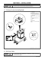
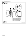
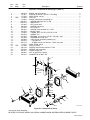
July 1995 Form: OM-116J Effective With Serial No. KF943539 OWNER’S MANUAL Thunderbolt 225 CC/AC Welding Power Source For SMAW (Stick) Welding Rated Welding Output Amperage Range Maximum OpenCircuit Voltage Amperes Input at Rated Load Output 60 Hz, Single-Phase Overall Dimensions 230 V KW 47.5 (8.6)* 7.2 (0.22)* Weight Height: 21-1/2 in (546 mm) 225 A @ 25 Volts AC, 20% Duty Cycle Low: 30 – 150A 80 VAC High: 40 – 225A Net: 100 lb (45 kg) Width: 12-1/2 in (318 mm) Ship: 105 lb (48 kg) Depth: 14 in (356 mm) *While idling cover_om 4/95 – ST-052 359-D 1995 MILLER Electric Mfg. Co. PRINTED IN USA From Miller to You Thank you and congratulations on choosing Miller. Now you can get the job done and get it done right. We know you don’t have time to do it any other way. That’s why when Niels Miller first started building arc welders in 1929, he made sure his products offered long-lasting value and superior quality. Like you, his customers couldn’t afford anything less. Miller products had to be more than the best they could be. They had to be the best you could buy. Today, the people that build and sell Miller products continue the tradition. They’re just as committed to providing equipment and service that meets the high standards of quality and value established in 1929. This Owner’s Manual is designed to help you get the most out of your Miller products. Please take time to read the Safety precautions. They will help you protect yourself against potential hazards on the worksite. We’ve made installation and operation quick and easy. With Miller you can count on years of reliable service with proper maintenance. And if for some reason the unit needs repair, there’s a Troubleshooting section that will help you Miller is the first welding figure out what the problem is. The parts list equipment manufacturer in will then help you to decide which exact part the U.S.A. to be registered to the ISO 9001 Quality System you may need to fix the problem. Warranty and Standard. service information for your particular model are also provided. Miller Electric manufactures a full line of welders and welding related equipment. For information on other quality Miller products, contact your local Miller distributor to receive the latest full line catalog or individual catalog sheets. To locate your nearest distributor or service agency call 1-800-4-A-Miller, or visit us at www.MillerWelds.com on the web. Working as hard as you do – every power source from Miller is backed by the most hassle-free warranty in the business. Miller offers a Technical Manual which provides more detailed service and parts information for your unit. To obtain a Technical Manual, contact your local distributor. Your distributor can also supply you with Welding Process Manuals such as SMAW, GTAW, GMAW, and GMAW-P. SECTION 1 – SAFETY PRECAUTIONS FOR ARC WELDING safety_stickom1 6/95 1-1. Symbol Usage Means Warning! Watch Out! There are possible hazards with this procedure! The possible hazards are shown in the adjoining symbols. Y Marks a special safety message. . Means NOTE; not safety related. This group of symbols means Warning! Watch Out! possible ELECTRIC SHOCK, MOVING PARTS, and HOT PARTS hazards. Consult symbols and related instructions below for necessary actions to avoid the hazards. 1-2. Arc Welding Hazards WARNING The symbols shown below are used throughout this manual to call attention to and identify possible hazards. When you see the symbol, watch out, and follow the related instructions to avoid the hazard. The safety information given below is only a summary of the more complete safety information found in the Safety Standards listed in Section 1-4. Read and follow all Safety Standards. Only qualified persons should install, operate, maintain, and repair this unit. During operation, keep everybody, especially children, away. ELECTRIC SHOCK can kill. Touching live electrical parts can cause fatal shocks or severe burns. The electrode and work circuit is electrically live whenever the output is on. The input power circuit and machine internal circuits are also live when power is on. Incorrectly installed or improperly grounded equipment is a hazard. 1. Do not touch live electrical parts. 2. Wear dry, hole-free insulating gloves and body protection. 3. Insulate yourself from work and ground using dry insulating mats or covers big enough to prevent any physical contact with the work or ground. 4. Disconnect input power before installing or servicing this equipment. Lockout/tagout input power according to OSHA 29 CFR 1910.147 (see Safety Standards). 5. Properly install and ground this equipment according to its Owner’s Manual and national, state, and local codes. 6. Always verify the supply ground – check and be sure that input power cord ground wire is properly connected to ground terminal ARC RAYS can burn eyes and skin; NOISE can damage hearing; FLYING SLAG OR SPARKS can injure eyes. Arc rays from the welding process produce intense visible and invisible (ultraviolet and infrared) rays that can burn eyes and skin. Noise from some processes can damage hearing. Chipping, grinding, and welds cooling throw off pieces of metal or slag. NOISE be Welding produces fumes and gases. Breathing these fumes and gases can be hazardous to your health. 1. Keep your head out of the fumes. Do not breathe the fumes. 2. If inside, ventilate the area and/or use exhaust at the arc to remove welding fumes and gases. 3. If ventilation is poor, use an approved air-supplied respirator. 4. Read the Material Safety Data Sheets (MSDSs) and the manufacturer’s instruction for metals, consumables, coatings, cleaners, and degreasers. OM-116J – 7/95 8. 9. 10. 11. 12. 13. 14. 15. 16. 17. ARC RAYS 2. Wear a welding helmet fitted with a proper shade of filter to protect your face and eyes when welding or watching (see ANSI Z49.1 and Z87.1 listed in Safety Standards). 3. Wear approved safety glasses with side shields. 4. Use protective screens or barriers to protect others from flash and glare; warn others not to watch the arc. 5. Wear protective clothing made from durable, flame-resistant material (wool and leather) and foot protection. 1. Use approved ear plugs or ear muffs if noise level is high. FUMES AND GASES can hazardous to your health. 7. in disconnect box or that cord plug is connected to a properly grounded receptacle outlet. When making input connections, attach proper grounding conductor first – double-check connections. Frequently inspect input power cord for damage or bare wiring – replace cord immediately if damaged – bare wiring can kill. Turn off all equipment when not in use. Do not use worn, damaged, undersized, or poorly spliced cables. Do not drape cables over your body. If earth grounding of the workpiece is required, ground it directly with a separate cable – do not use work clamp or work cable. Do not touch electrode if you are in contact with the work, ground, or another electrode from a different machine. Use only well-maintained equipment. Repair or replace damaged parts at once. Maintain unit according to manual. Wear a safety harness if working above floor level. Keep all panels and covers securely in place. Clamp work cable with good metal-to-metal contact to workpiece or worktable as near the weld as practical. 5. Work in a confined space only if it is well ventilated, or while wearing an air-supplied respirator. Always have a trained watchperson nearby. Welding fumes and gases can displace air and lower the oxygen level causing injury or death. Be sure the breathing air is safe. 6. Do not weld in locations near degreasing, cleaning, or spraying operations. The heat and rays of the arc can react with vapors to form highly toxic and irritating gases. 7. Do not weld on coated metals, such as galvanized, lead, or cadmium plated steel, unless the coating is removed from the weld area, the area is well ventilated, and if necessary, while wearing an air-supplied respirator. The coatings and any metals containing these elements can give off toxic fumes if welded. OM-116 Page 1 CYLINDERS can explode if damaged. Shielding gas cylinders contain gas under high pressure. If damaged, a cylinder can explode. Since gas cylinders are normally part of the welding process, be sure to treat them carefully. WELDING explosion. can cause fire or Welding on closed containers, such as tanks, drums, or pipes, can cause them to blow up. Sparks can fly off from the welding arc. The flying sparks, hot workpiece, and hot equipment can cause fires and burns. Accidental contact of electrode to metal objects can cause sparks, explosion, overheating, or fire. Check and be sure the area is safe before doing any welding. 1. Protect yourself and others from flying sparks and hot metal. 2. Do not weld where flying sparks can strike flammable material. 3. Remove all flammables within 35 ft (10.7 m) of the welding arc. If this is not possible, tightly cover them with approved covers. 4. Be alert that welding sparks and hot materials from welding can easily go through small cracks and openings to adjacent areas. 1. Protect compressed gas cylinders from excessive heat, mechanical shocks, slag, open flames, sparks, and arcs. 2. Keep cylinders away from any welding or other electrical circuits. 3. Never drape an electrode holder over a gas cylinder. 4. Never allow a welding electrode to touch any cylinder. 5. Never weld on a pressurized cylinder – explosion will result. 5. Watch for fire, and keep a fire extinguisher nearby. 6. Be aware that welding on a ceiling, floor, bulkhead, or partition can cause fire on the hidden side. 7. Do not weld on closed containers such as tanks, drums, or pipes, unless they are properly prepared according to AWS F4.1 (see Safety Standards). 8. Connect work cable to the work as close to the welding area as practical to prevent welding current from traveling long, possibly unknown paths and causing electric shock and fire hazards. 9. Do not use welder to thaw frozen pipes. 10. Remove stick electrode from holder when not in use. 11. Wear oil-free protective garments such as leather gloves, heavy shirt, cuffless trousers, high shoes, and a cap. 12. Remove any combustibles, such as a butane lighter or matches, from your person before doing any welding. 1-3. Additional Installation, Operation, And Maintenance Hazards FIRE OR EXPLOSION can result from placing unit on, over, or near combustible surfaces. MAGNETIC CURRENTS operation. 1. Do not install unit on, over, or near combustible surfaces or flammables. 1. Wearers should consult their doctor before going near arc welding, gouging, or spot welding operations. HOT PARTS can cause severe burns. FLYING PIECES OF METAL or DIRT can injure eyes. 1. Do not touch hot parts bare handed. Allow cooling period before beginning. FIELDS FROM HIGH can affect pacemaker 1. Wear safety glasses with side shields or face shield. 1-4. Principal Safety Standards Safety in Welding and Cutting, ANSI Standard Z49.1, from American Welding Society, 550 N.W. LeJeune Rd, Miami FL 33126 Safety and Health Standards, OSHA 29 CFR 1910, from Superintendent of Documents, U.S. Government Printing Office, Washington, D.C. 20402. Recommended Safe Practices for the Preparation for Welding and Cutting of Containers That Have Held Hazardous Substances, American Welding Society Standard AWS F4.1, from American Welding Society, 550 N.W. LeJeune Rd, Miami, FL 33126 National Electrical Code, NFPA Standard 70, from National Fire Protection Association, Batterymarch Park, Quincy, MA 02269. Code for Safety in Welding and Cutting, CSA Standard W117.2, from Canadian Standards Association, Standards Sales, 178 Rexdale Boulevard, Rexdale, Ontario, Canada M9W 1R3. Safe Practices For Occupation And Educational Eye And Face Protection, ANSI Standard Z87.1, from American National Standards Institute, 1430 Broadway, New York, NY 10018. Cutting And Welding Processes, NFPA Standard 51B, from National Fire Protection Association, Batterymarch Park, Quincy, MA 02269. 1-5. EMF Information Considerations About Welding And The Effects Of Low Frequency Electric And Magnetic Fields The following is a quotation from the General Conclusions Section of the U.S. Congress, Office of Technology Assessment, Biological Effects of Power Frequency Electric & Magnetic Fields – Background Paper, OTA-BP-E-53 (Washington, DC: U.S. Government Printing Office, May 1989): “. . . there is now a very large volume of scientific findings based on experiments at the cellular level and from studies with animals and people which clearly establish that low frequency magnetic fields can interact with, and produce changes in, biological systems. While most of this work is of very high quality, the results are complex. Current scientific understanding does not yet allow us to interpret the evidence in a single coherent framework. Even more frustrating, it does not yet allow us to draw definite conclusions about questions of possible risk or to offer clear science-based advice on strategies to minimize or avoid potential risks.” OM-116 Page 2 To reduce magnetic fields in the workplace, use the following procedures: 1. Keep cables close together by twisting or taping them. 2. Arrange cables to one side and away from the operator. 3. Do not coil or drape cables around the body. 4. Keep welding power source and cables as far away as practical. 5. Connect work clamp to workpiece as close to the weld as possible. About Pacemakers: The above procedures are also recommended for pacemaker wearers. Consult your doctor for complete information. SECTION 2 – INSTALLATION NOTE See User’s Guide on unit for process connection information. 2-1. Selecting A Location And Installing Handle 1 Lifting Area Place hands where shown to move unit. Get help when moving unit. 2 3 5 6 Running Gear Mounting Holes Rating Label Locate unit near correct input power. 4 4 5 6 Amperage Adjustment Rod Handle Pin Install as shown. Move pin into locked position shown. 1 Locked Pin 3 18 in (457 mm) for airflow 2 ST-052 359-D / Ref. ST-151 556 / ST-155 573-A 2-2. Weld Output Cables NOTE For weld output cable replacements or extensions, contact your Factory Authorized Service Agent. OM-116 Page 3 2-3. Connecting Input Power Y Have only qualified persons make this installation. L1 L2 GND/PE 230 VAC, 1 GND/PE L1 L2 GND/PE Connect First Tools Needed: Minimum input and grounding conductor size is 10 AWG/Kcmil, not to exceed 87 ft (26 m) in length. Install conductors in conduit or equivalent into a deenergized line disconnect device. Maximum recommended standard fuse or circuit breaker rating is 70 amperes. Size and ratings must comply with applicable codes. 3/8 in ssb2.2 3/93 – ST-155 576-B OM-116 Page 4 SECTION 3 – OPERATION 3-1. Controls 1 2 3 4 Amperage Control Amperage Range Indicator Electrode (30–150 A) Weld Output Receptacle Electrode (40–225 A) Weld Output Receptacle When welding below 150 amps, use 30–150 A receptacle. 5 6 Work Weld Output Receptacle Power Switch 1 2 3 4 6 5 Ref. ST-155 574 / Ref. SC-107 516-F 3-2. Duty Cycle Chart And Volt-Ampere Curves Duty Cycle is percentage of 10 minutes that unit can weld at rated load without overheating. Y 20% Duty Cycle at 225 Amperes. Exceeding duty cycle can damage unit and void warranty. 2 Minutes Welding The volt-ampere curves show the minimum and maximum voltage and amperage output capabilities. Curves of other settings fall between the curves shown. 8 Minutes Resting rduty1 5/95 – ST-001 836-A / ST-001 844-A OM-116 Page 5 SECTION 4 – MAINTENANCE & TROUBLESHOOTING 4-1. Routine Maintenance Y Disconnect power before maintaining. 3 Months Repair Or Replace Cracked Cables Replace Unreadable Labels Clean And Tighten Weld Connections 6 Months 12 Months Blow Out Or Vacuum Inside, During Heavy Service, Clean Monthly OR Lubricate Shunt Block 4-2. Lubricating Shunt Block And Anti-Noise Adjustment Y Turn Off welding power source and disconnect input power. 1 Shunt Block Apply light coating of high-temperature grease to shaded areas of both shunt blocks. Install amperage control handle and locking pin. Turn handle to spread grease evenly. Y Install wrapper before turning On power. 2 Noise Adjustment Screws If shunt block vibrates and becomes noisy, tighten adjustment screws 1/4 turn. Install wrapper, handle, and pin, turn On unit, and check for shunt noise. Repeat procedure until noise stops. Do not overtighten. Call your nearest Factory Authorized Service Agent if noise continues. Reinstall wrapper, handle, and pin. 1 2 Tools Needed: 1 ST-155 498-A OM-116 Page 6 4-3. Troubleshooting Trouble Remedy No weld output; fan does not run. Be sure line disconnect switch is in On position (see Section 2-3). Check and replace line fuses if open. Reset breakers if necessary (see Section 2-3). Fan does not run; weld output okay. Be sure nothing is blocking movement of fan. If fan does not run freely, replace fan motor. Erratic weld current. Clean and tighten all weld cable connections. Erratic arc with excessive spatter. Use dry, properly stored electrodes. See User’s Guide also. Shorten arc length. See User’s Guide also. Reduce amperage setting (see Section 3-1). Electrode freezing to work. Use dry, properly stored electrodes. See User’s Guide also. Increase arc length. See User’s Guide also. Increase amperage setting (see Section 3-1). SECTION 5 – ELECTRICAL DIAGRAM SA-108 072 Figure 5-1. Circuit Diagram For Welding Power Source OM-116 Page 7 SECTION 6 – PARTS LIST Item No. Dia. Mkgs. Part No. Description Quantity Figure 6-1. Main Assembly . . . 1 . . . . . . . . . . 039 800 . . RECEPTACLE, jack plug red (consisting of) . . . . . . . . . . . . . . . . . . . . . . . . . . . . . . . 2 . . . . . . . . . . 006 095 . . . . RECEPTACLE & NUT, jack plug red . . . . . . . . . . . . . . . . . . . . . . . . . . . . . . . . . . . . 3 . . . . . . . . . . 010 291 . . . . WASHER, flat nylafil .625 ID x 1.250 OD x .125thk . . . . . . . . . . . . . . . . . . . . . . . 4 . . . . . . . . . . 604 668 . . . . NUT, stl slflkg hex med fnsh .500-20 . . . . . . . . . . . . . . . . . . . . . . . . . . . . . . . . . . . . 5 . . . . . . . . . . 174 491 . . . . WASHER, lock intl tooth .500 . . . . . . . . . . . . . . . . . . . . . . . . . . . . . . . . . . . . . . . . . . . . . . . . . . . . . . . 601 881 . . . . NUT, stl hex jam .500-20 . . . . . . . . . . . . . . . . . . . . . . . . . . . . . . . . . . . . . . . . . . . . . . 6 . . . . S1 . *124 511 . . SWITCH, tgl DPST 40A 600VAC . . . . . . . . . . . . . . . . . . . . . . . . . . . . . . . . . . . . . . . . . 7 . . . . . . . . . . 088 372 . . CASE SECTION, base/front/rear . . . . . . . . . . . . . . . . . . . . . . . . . . . . . . . . . . . . . . . . . 8 . . . . . . . . . . 024 103 . . BLANK, snap-in .750mtg hole . . . . . . . . . . . . . . . . . . . . . . . . . . . . . . . . . . . . . . . . . . . 9 . . . . . . . . . . 111 443 . . BUSHING, strain relief .240/.510 ID x .875mtg hole . . . . . . . . . . . . . . . . . . . . . . . . . 10 . . . . . . . . . . 088 297 . . CORD SET, 250V 6-50P 12ga 3/c 6ft . . . . . . . . . . . . . . . . . . . . . . . . . . . . . . . . . . . . . 11 . . . . . . . . . . 039 778 . . RECEPTACLE, str 2P3W 50A 250V . . . . . . . . . . . . . . . . . . . . . . . . . . . . . . . . . . . . . . 12 . . . . . . . . . . 005 656 . . BLADE, fan 6 in 4wg 30deg .175 bore CW . . . . . . . . . . . . . . . . . . . . . . . . . . . . . . . . 13 . . . FM . . 123 468 . . MOTOR, 230V 50/60Hz 3000RPM . . . . . . . . . . . . . . . . . . . . . . . . . . . . . . . . . . . . . . . 14 . . . . . . . . . . 082 272 . . WRAPPER . . . . . . . . . . . . . . . . . . . . . . . . . . . . . . . . . . . . . . . . . . . . . . . . . . . . . . . . . . . 15 . . . . . . . . . . 009 926 . . PIN, handle control current . . . . . . . . . . . . . . . . . . . . . . . . . . . . . . . . . . . . . . . . . . . . . . 16 . . . . . . . . . . 009 433 . . HANDLE, control current . . . . . . . . . . . . . . . . . . . . . . . . . . . . . . . . . . . . . . . . . . . . . . . . 17 . . . . T1 . . 117 668 . . TRANSFORMER & SHUNT, (230V) (Fig 6-2) . . . . . . . . . . . . . . . . . . . . . . . . . . . . . . 18 . . . . . . . . . . 010 142 . . CLAMP, nyl .312clp dia . . . . . . . . . . . . . . . . . . . . . . . . . . . . . . . . . . . . . . . . . . . . . . . . . 19 . . . . . . . . . . . . . . . . . . . . . NAMEPLATE, (order by model and serial number) . . . . . . . . . . . . . . . . . . . . . . . . . . . . . . . . . . . . . . 174 453 . . HOLDER, electrode w/cable . . . . . . . . . . . . . . . . . . . . . . . . . . . . . . . . . . . . . . . . . . . . . . . . . . . . . . . . . . 174 456 . . GROUND CABLE, w/clamp 10ft . . . . . . . . . . . . . . . . . . . . . . . . . . . . . . . . . . . . . . 3 1 1 2 1 1 1 1 2 1 1 1 1 1 1 1 1 1 2 1 1 1 16 15 4 1 4 5 10 14 9 3 8 11 Includes Item 2 7 6 12 13 2 17 Fig 6-2 19 18 Ref. SD-052 395-E Figure 6-1. Main Assembly *Recommended Spare Parts. BE SURE TO PROVIDE MODEL AND SERIAL NUMBER WHEN ORDERING REPLACEMENT PARTS. OM-116 Page 8 Item No. Dia. Mkgs. Part No. Description Quantity Figure 6-2. Transformer & Shunt (Fig 6-1 Item 17) ... ... ... ... ... ... ... ... ... ... ... ... ... ... ... ... ... ... ... ... ... ... ... ... ... ... 1 2 3 4 5 6 7 8 9 10 11 12 13 14 15 16 17 18 19 20 21 22 23 24 25 26 . . . . . . . . . . . 080 522 . . . . . . . . . . . 147 907 . . . . . . . . . . . 112 569 . . . SEC . . . 112 488 . . . . . . . . . . . 119 962 . . . . . . . . . +081 821 . . . . . . . . . +009 312 . . . . . . . . . . . 601 860 . . . . . . . . . . . 009 428 . . . . . . . . . . . 021 100 . . . . . . . . . . . 602 087 . . . . . . . . . . . 036 356 . . . . . . . . . . . 119 963 . . . . . . . . . . . 020 284 . . . . . . . . . . . 010 653 . . . . . . . . . . . 010 929 . . . . . . . . . . . 024 869 . . . . . . . . . . . 024 612 . . . . . . . . . . . 602 176 . . . . . . . . . . . 112 573 . . . PRI . . . 112 498 . . . . . . . . . . . 605 129 . . . . . . . . . . . 020 300 . . . . . . . . . . . 020 301 . . . . . . . . . . . 089 800 . . . . . . . . . . . 602 241 . . . BLOCK, anti-noise shunt . . . . . . . . . . . . . . . . . . . . . . . . . . . . . . . . . . . . . . . . . . . . . . . SCREW, set stl hdls .312-18 x 1.500 slflkg . . . . . . . . . . . . . . . . . . . . . . . . . . . . . . . INSULATION, coil sec . . . . . . . . . . . . . . . . . . . . . . . . . . . . . . . . . . . . . . . . . . . . . . . . . COIL, sec . . . . . . . . . . . . . . . . . . . . . . . . . . . . . . . . . . . . . . . . . . . . . . . . . . . . . . . . . . . . SHUNT, transformer (consisting of) . . . . . . . . . . . . . . . . . . . . . . . . . . . . . . . . . . . . . . . SCREW, slftpg filph 8-11 x .500 . . . . . . . . . . . . . . . . . . . . . . . . . . . . . . . . . . . . . . . . INDICATOR . . . . . . . . . . . . . . . . . . . . . . . . . . . . . . . . . . . . . . . . . . . . . . . . . . . . . . . . . NUT, stl hex 8-32 . . . . . . . . . . . . . . . . . . . . . . . . . . . . . . . . . . . . . . . . . . . . . . . . . . . . . SCREW, lead shunt . . . . . . . . . . . . . . . . . . . . . . . . . . . . . . . . . . . . . . . . . . . . . . . . . . . NUT, lead scr . . . . . . . . . . . . . . . . . . . . . . . . . . . . . . . . . . . . . . . . . . . . . . . . . . . . . . . . SCREW, mach stl rdh 8-32 x 1.250 . . . . . . . . . . . . . . . . . . . . . . . . . . . . . . . . . . . . . BLOCK, shunt . . . . . . . . . . . . . . . . . . . . . . . . . . . . . . . . . . . . . . . . . . . . . . . . . . . . . . . TUBING, phen .531 ID x .875 OD x .500 . . . . . . . . . . . . . . . . . . . . . . . . . . . . . . . . WEDGE, coil . . . . . . . . . . . . . . . . . . . . . . . . . . . . . . . . . . . . . . . . . . . . . . . . . . . . . . . . BEARING, thr oil imprg .375 ID x .750 OD x .062 . . . . . . . . . . . . . . . . . . . . . . . . . WASHER, flat stl spr .375 . . . . . . . . . . . . . . . . . . . . . . . . . . . . . . . . . . . . . . . . . . . . . COLLAR, set w/screws (consisting of) . . . . . . . . . . . . . . . . . . . . . . . . . . . . . . . . . . . . . COLLAR, set . . . . . . . . . . . . . . . . . . . . . . . . . . . . . . . . . . . . . . . . . . . . . . . . . . . . . . . . . SCREW, set stl sch .250-20 x .187knr cup point . . . . . . . . . . . . . . . . . . . . . . . INSULATION, coil pri . . . . . . . . . . . . . . . . . . . . . . . . . . . . . . . . . . . . . . . . . . . . . . . . . . COIL, pri (230V) . . . . . . . . . . . . . . . . . . . . . . . . . . . . . . . . . . . . . . . . . . . . . . . . . . . . . . SCREW, cap stl hexhd .250-20 x 7.000 . . . . . . . . . . . . . . . . . . . . . . . . . . . . . . . . . . WEDGE, rear removable . . . . . . . . . . . . . . . . . . . . . . . . . . . . . . . . . . . . . . . . . . . . . . . GUIDE, wedge rear . . . . . . . . . . . . . . . . . . . . . . . . . . . . . . . . . . . . . . . . . . . . . . . . . . . NUT, stl flg lkd hex .250-20 . . . . . . . . . . . . . . . . . . . . . . . . . . . . . . . . . . . . . . . . . . . . . WASHER, flat stl SAE .250 . . . . . . . . . . . . . . . . . . . . . . . . . . . . . . . . . . . . . . . . . . 6 4 4 2 1 1 1 1 2 1 1 2 1 1 1 1 1 1 1 2 2 1 1 2 1 1 1 9 7 8 10 5 11 Includes Items 7 thru 19 12 13 20 4 3 2 14 21 15 16 18 19 1 17 22 23 26 25 24 23 ST-052 396-F Figure 6-2. Transformer & Shunt +Not part of Shunt Assembly BE SURE TO PROVIDE MODEL AND SERIAL NUMBER WHEN ORDERING REPLACEMENT PARTS. OM-116 Page 9 OPTIONS AND ACCESSORIES No. 11A RUNNING GEAR (#041 637) A handle and two wheels with solid rubber tires mount easily to the frame of the Thunderbolt 225, providing convenient portability. 4/95 Effective January 1, 2000 (Equipment with a serial number preface of “LA” or newer) This limited warranty supersedes all previous Miller warranties and is exclusive with no other guarantees or warranties expressed or implied. Warranty Questions? Call 1-800-4-A-MILLER for your local Miller distributor. Your distributor also gives you ... Service You always get the fast, reliable response you need. Most replacement parts can be in your hands in 24 hours. Support Need fast answers to the tough welding questions? Contact your distributor. The expertise of the distributor and Miller is there to help you, every step of the way. * LIMITED WARRANTY – Subject to the terms and conditions below, Miller Electric Mfg. Co., Appleton, Wisconsin, warrants to its original retail purchaser that new Miller equipment sold after the effective date of this limited warranty is free of defects in material and workmanship at the time it is shipped by Miller. THIS WARRANTY IS EXPRESSLY IN LIEU OF ALL OTHER WARRANTIES, EXPRESS OR IMPLIED, INCLUDING THE WARRANTIES OF MERCHANTABILITY AND FITNESS. Within the warranty periods listed below, Miller will repair or replace any warranted parts or components that fail due to such defects in material or workmanship. Miller must be notified in writing within thirty (30) days of such defect or failure, at which time Miller will provide instructions on the warranty claim procedures to be followed. Miller shall honor warranty claims on warranted equipment listed below in the event of such a failure within the warranty time periods. All warranty time periods start on the date that the equipment was delivered to the original retail purchaser, or one year after the equipment is sent to a North American distributor or eighteen months after the equipment is sent to an International distributor. 1. 5 Years Parts – 3 Years Labor * * 2. 3 Years — Parts and Labor * * * * * * 3. Original main power rectifiers Inverters (input and output rectifiers only) Transformer/Rectifier Power Sources Plasma Arc Cutting Power Sources Semi-Automatic and Automatic Wire Feeders Inverter Power Supplies Intellitig Engine Driven Welding Generators (NOTE: Engines are warranted separately by the engine manufacturer.) 1 Year — Parts and Labor * * * * * * * * * * * * * * * * * DS-2 Wire Feeder Motor Driven Guns (w/exception of Spoolmate 185 & Spoolmate 250) Process Controllers Positioners and Controllers Automatic Motion Devices RFCS Foot Controls Induction Heating Power Sources Water Coolant Systems HF Units Grids Maxstar 140 Spot Welders Load Banks Miller Cyclomatic Equipment Running Gear/Trailers Plasma Cutting Torches (except APT & SAF Models) Field Options (NOTE: Field options are covered under True Blue for the remaining warranty period of the product they are installed in, or for a minimum of one year — whichever is greater.) 4. 6 Months — Batteries 5. 90 Days — Parts * * MIG Guns/TIG Torches Induction Heating Coils and Blankets * * * * * APT, ZIPCUT & PLAZCUT Model Plasma Cutting Torches Remote Controls Accessory Kits Replacement Parts (No labor) Spoolmate 185 & Spoolmate 250 Canvas Covers Miller’s True Blue Limited Warranty shall not apply to: 1. Consumable components; such as contact tips, cutting nozzles, contactors, brushes, slip rings, relays or parts that fail due to normal wear. 2. Items furnished by Miller, but manufactured by others, such as engines or trade accessories. These items are covered by the manufacturer’s warranty, if any. 3. Equipment that has been modified by any party other than Miller, or equipment that has been improperly installed, improperly operated or misused based upon industry standards, or equipment which has not had reasonable and necessary maintenance, or equipment which has been used for operation outside of the specifications for the equipment. MILLER PRODUCTS ARE INTENDED FOR PURCHASE AND USE BY COMMERCIAL/INDUSTRIAL USERS AND PERSONS TRAINED AND EXPERIENCED IN THE USE AND MAINTENANCE OF WELDING EQUIPMENT. In the event of a warranty claim covered by this warranty, the exclusive remedies shall be, at Miller’s option: (1) repair; or (2) replacement; or, where authorized in writing by Miller in appropriate cases, (3) the reasonable cost of repair or replacement at an authorized Miller service station; or (4) payment of or credit for the purchase price (less reasonable depreciation based upon actual use) upon return of the goods at customer’s risk and expense. Miller’s option of repair or replacement will be F.O.B., Factory at Appleton, Wisconsin, or F.O.B. at a Miller authorized service facility as determined by Miller. Therefore no compensation or reimbursement for transportation costs of any kind will be allowed. TO THE EXTENT PERMITTED BY LAW, THE REMEDIES PROVIDED HEREIN ARE THE SOLE AND EXCLUSIVE REMEDIES. IN NO EVENT SHALL MILLER BE LIABLE FOR DIRECT, INDIRECT, SPECIAL, INCIDENTAL OR CONSEQUENTIAL DAMAGES (INCLUDING LOSS OF PROFIT), WHETHER BASED ON CONTRACT, TORT OR ANY OTHER LEGAL THEORY. ANY EXPRESS WARRANTY NOT PROVIDED HEREIN AND ANY IMPLIED WARRANTY, GUARANTY OR REPRESENTATION AS TO PERFORMANCE, AND ANY REMEDY FOR BREACH OF CONTRACT TORT OR ANY OTHER LEGAL THEORY WHICH, BUT FOR THIS PROVISION, MIGHT ARISE BY IMPLICATION, OPERATION OF LAW, CUSTOM OF TRADE OR COURSE OF DEALING, INCLUDING ANY IMPLIED WARRANTY OF MERCHANTABILITY OR FITNESS FOR PARTICULAR PURPOSE, WITH RESPECT TO ANY AND ALL EQUIPMENT FURNISHED BY MILLER IS EXCLUDED AND DISCLAIMED BY MILLER. Some states in the U.S.A. do not allow limitations of how long an implied warranty lasts, or the exclusion of incidental, indirect, special or consequential damages, so the above limitation or exclusion may not apply to you. This warranty provides specific legal rights, and other rights may be available, but may vary from state to state. In Canada, legislation in some provinces provides for certain additional warranties or remedies other than as stated herein, and to the extent that they may not be waived, the limitations and exclusions set out above may not apply. This Limited Warranty provides specific legal rights, and other rights may be available, but may vary from province to province. miller_warr 7/00 Owner’s Record Please complete and retain with your personal records. Model Name Serial/Style Number Purchase Date (Date which equipment was delivered to original customer.) Distributor Address City State Zip For Service Call 1-800-4-A-Miller or see our website at www.MillerWelds.com to locate a DISTRIBUTOR or SERVICE AGENCY near you. Always provide Model Name and Serial/Style Number. Contact your Distributor for: Welding Supplies and Consumables Options and Accessories Personal Safety Equipment Service and Repair Miller Electric Mfg. Co. An Illinois Tool Works Company 1635 West Spencer Street Appleton, WI 54914 USA Replacement Parts Training (Schools, Videos, Books) International Headquarters–USA USA Phone: 920-735-4505 Auto-Attended USA & Canada FAX: 920-735-4134 International FAX: 920-735-4125 Technical Manuals (Servicing Information and Parts) Circuit Diagrams European Headquarters – United Kingdom Phone: 44 (0) 1204-593493 FAX: 44 (0) 1204-598066 Welding Process Handbooks www.MillerWelds.com Contact the Delivering Carrier for: File a claim for loss or damage during shipment. For assistance in filing or settling claims, contact your distributor and/or equipment manufacturer’s Transportation Department. PRINTED IN USA 2000 Miller Electric Mfg. Co. 6/00