1
Operator's Manual
CRRFTSMRN °
4.5 Horse Power
YARD VACUUM
Model No. 247.770110
CAUTION: Before using
this product, read this
manual and follow all
Safety
Rules and
Operating
Instructions,
Safety
Assembly
Operation
Maintenance
Parts
Espa_ol
Sears, Roebuck and Co., Hoffman Estates, IL 60179, U.S.A.
Visit our Sears website: www.sears.com/craftsman
Printed
in U.S.A.
FORM NO. 770-10233G
(8/01 )
Content
Page
Warranty
2
Service and Adjustments
12
Safety
3
Storage
14
Assembly
5
Troubleshooting
15
Operation
7
Parts List
16
Maintenance
10
Limited Warranty
Content
on Craftsman
Page
Yard Vacuum
For one (1) year from the date of purchase, ifthis Craftsman Equipment is maintained, lubricated, and tuned up
according to the instructionsto the operator's manual, Sears will repair or replace free of charge any parts found
to be defective in material or workmanship. Warranty service is available free of charge by returning Craftsman
equipment to your nearest Sears Service Center. In-home warranty service is available but a trip charge will
apply. This Warranty applies only while this product is in the United States.
This Warranty does not cover:
•
Expendable items which become worn during normal use, such as spark plugs, air cleaners, belts, and oil
filters.
•
Tire replacement or repair caused by punctures from outside objects, such as nails, thorns, stumps, or glass.
•
Repairs necessary because of operator abuse, including but not limited to, damage caused by objects, such
as stones or metal debris, oversized stock, impacting objects that bend the frame or crankshaft, or overspeeding the engine.
•
Repairs necessary because of operator negligence, including but not limited to, electrical and mechanical
damage caused by improper storage, failure to use the proper grade and amount of engine oil, or failure to
maintain the equipment according to the instructions contained in the operator's manual.
•
Engine (fuel system) cleaning or repairs caused by fuel determine to be contaminated or oxidized (stale). In
general, fuel should be used within 30 days of its purchase date.
•
Equipment used for commercial or rental purposes.
TO LOCATE THE NEAREST SEARS SERVICE CENTER OR TO SCHEDULE SERVICE, SIMPLY CONTACT
SEARS AT 1-800-4-MY-HOME.
This warranty gives you specific legal rights and you may also have other rights, which vary from state to state.
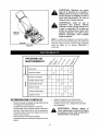
PRODUCT SPECIFICATION
Horsepower:
4.5 Horse Power
Engine Oil Type
SAE 30
Engine Oil Capacity
20 Ounces
1 1/2 Quarts
Fuel Capacity:
Spark Plug
Spark Plug Gap
Champion RJ-19LM
.030"
Model Number ....... ..2..4..7..:
.7..7...0..1..1...0.
...........................
Serial Number ...........................................................
Date of Purchase ......................................................
Record both serial number and date of purchase and
keep in a safe place for future reference.
WARNING:
This symbol points out important safety instructions which, if not followed, could
endanger the personal safety and/or property of yourself and others. Read and follow all
instructions in this manual before attempting to operate this machine. Failure to comply with these
instructions may result in personal injury. When you see this symbol - heed its warning.
WARNING:
Engine Exhaust, some of its constituents,
components contain or emit chemicals
and birth defects or other reproductive
DANGER:
and certain vehicle
known to State of California to cause cancer
harm.
This machine was built to be operated according to the rules for safe operation in this
manual. As with any type of power equipment, carelessness or error on the part of the operator can
result in serious injury. This machine is capable of amputating hands and feet and throwing objects.
Failure to observe the following safety instructions could result in serious injury or death.
TRAINING
1.
2.
3.
4.
5.
6.
7.
8.
Read, understand, and follow all instructions on
the machine and in the manual(s) before
attempting to assemble and operate. Keep this
manual in a safe place for future and regular
reference and for ordering replacement parts.
Be familiar with all controls and their proper
operation. Know how to stop the machine and
disengage them quickly.
Never allow children under 16 years old to
3.
operate this machine. Children 16 years old and
over should read and understand the operation
instructions and safety rules in this manual and
should be trained and supervised by a parent.
Never allow adults to operate this machine
without proper instruction.
Keep bystanders, helpers, pets, and children at
least 75 feet from the machine while it is in
4.
operation. Stop machine if anyone enters the
area.
Never run an engine indoors or in a poorly
ventilated area. Engine exhaust contains carbon
monoxide, an odorless and deadly gas.
Do not put hands and feet near rotating parts or in
the feeding chambers and discharge opening.
Contact with the rotating impeller can amputate
fingers, hands, and feet.
Never attempt to unclog either the feed intake or
discharge opening, remove or empty vacuum
bag, or inspect and repair the machine while the
engine is running. Shut the engine off and wait
until all moving parts have come to a complete
stop. Disconnect the spark plug wire and ground
it against the engine.
PREPARATION
.
2.
Thoroughly inspect the area where the
equipment is to be used. Remove all rocks,
bottles, cans, or other foreign objects which could
be picked up or thrown and cause personal injury
or damage to the machine.
5.
6.
Always wear safety glasses or safety goggles
during operation or while performing an
adjustment or repair, to protect eyes. Thrown
objects which ricochet can cause serious injury to
the eyes.
Wear sturdy, rough-soled work shoes and closefitting slacks and shirts. Loose fitting clothes or
jewelry can be caught in movable parts. Never
operate this machine in bare feet or sandals.
Wear leather work gloves when feeding material
in the chipper chute.
Before starting, check all bolts and screws for
proper tightness to be sure the machine is in safe
working condition. Also, visually inspect machine
for any damage at frequent intervals.
Maintain or replace safety and instructions labels,
as necessary.
To avoid personal injury or property damage use
extreme care in handling gasoline. Gasoline is
extremely flammable and the vapors are
explosive. Serious personal injury can occur
when gasoline is spilled on yourself or your
clothes which can ignite. Wash your skin and
change clothes immediately.
a. Use only an approved gasoline container.
b. Extinguish all cigarettes, cigars, pipes, and
other sources of ignition.
c. Never fuel machine indoors.
d. Never remove gas cap or add while the
engine is hot or running.
e. Allow engine to cool at least two minutes
before refueling.
f. Never over fill fuel tank. Fill tank to no more
than 1/2 inch below bottom of filler neck to
provide space for fuel expansion.
g. Replace gasoline cap and tighten securely.
h. If gasoline is spilled, wipe it offthe engine
and equipment. Move machine to another
area. Wait 5 minutes before starting the
engine.
i. Neverstorethemachineorfuelcontainer
insidewherethereisanopenflame,spark,
orpilotlight(e.g.furnace,waterheater,
spaceheater,clothesdryer,etc.)
j. Toreduceafirehazard,keepmachine
free
ofgrass,leaves,or otherdebrisbuild-up.
Cleanupoilfuelspillageandremove
anyfuel
soakeddebris.
k. Allowmachine
tocoolatleast5 minutes
beforestoring.
9.
10.
11.
12.
OPERMION
1.
2.
3.
4.
5.
6.
7.
8.
Do not put hands and feet near rotating parts or in
the feeding chambers and discharge opening.
Contact with the rotating impeller can amputate
fingers, hands, and feet.
Before starting the machine, make sure the chipper
chute, feed intake, and cutting chamber are empty
and free of all debris.
Thoroughly inspect all material to be shredded and
remove any metal, rocks, bottles, cans, or other
foreign objects which could cause personal injury
or damage to the machine.
If the impeller strikes a foreign object or if your
machine should start making an unusual noise or
vibration, immediately shut the engine off. Allow the
impeller to come to a complete stop. Disconnect
the spark plug wire, ground it against the engine
and perform the following steps:
a. Inspect for damage.
b. Repair or replace any damaged parts.
c. Check for any loose parts and tighten to
assure continued safe operation.
Do not allow an accumulation of processed
material to build up in the discharge area. This can
prevent proper discharge and result in kickback of
material through the feed opening.
Do not attempt to shred or chip material larger than
specified on the machine or in this manual.
Personal injury or machine damage could result.
Never attempt to unclog either the feed intake or
discharge opening while the engine is running.
Shut the engine off, wait until all moving parts have
stopped, disconnect the spark plug wire and
ground it against the engine before clearing debris.
Never operate without vacuum bag and discharge
chute properly attached to the machine. Never
empty or change vacuum bag while the engine is
running. Zippered end of vacuum bag must be kept
closed at all times during operation.
13.
14.
15.
Never operate without either the inlet nozzle or
optional hose attachment properly attached to the
machine. Never attempt to attach or change either
attachment while the engine is running.
Keep all guards, deflectors and safety devices in
place and operating properly.
Keep your face and body back and to the side of
the chipper chute while feeding material into the
machine to avoid accidental kickback injuries.
Never operate this machine without good visibility
or light. Always be sure of your footing and keep a
firm hold on the handles.
Do not operate this machine on a gravel surface.
Do not operate this machine while under the
influence of alcohol or drugs.
Muffler and engine become hot and can cause a
burn. Do not touch.
16. Never pick up or carry machine while the engine is
running.
MAINTENANCE
ANDSTORAGE
1.
Never tamper with safety devices. Check their
proper operation regularly.
2. Check bolts and screws for proper tightness at
frequent intervals to keep the machine in safe
working condition. Also, visually inspect machine
for any damage and repair, if needed.
3. Before cleaning, repairing, or inspecting, stop the
engine and make certain the impeller and all
moving parts have stopped. Disconnect the spark
plug wire and ground it against the engine to
prevent unintended starting.
4. Do not change the engine governor settings or
overspeed the engine. The governor controls the
maximum safe operating speed of the engine.
5. Maintain or replace safety and instruction labels, as
necessary.
6. Follow this manual for safe loading, unloading,
transporting, and storage of this machine.
7. Never store the machine or fuel container inside
where there is an open flame, spark or pilot light
such as a water heater, furnace, clothes dryer, etc.
8. Always refer to the operator's manual for proper
instructions on off-season storage.
9. If the fuel tank has to be drained, do this outdoors.
10. Observe proper disposal laws and regulations for
gas, oil, etc. to protect the environment.
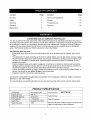
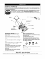
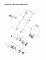
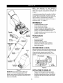
NOTE:
Reference
to right and left hand
Yard Vacuum is observed from
position. See Figure 1.
side of the
the
operating
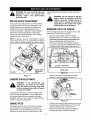
This Yard Vacuum has been completely assembled
at the factory, except for the handle, bag, and blower
chute. These parts are shipped loose in the carton.
A pair of safety glasses and a 20-oz. bottle of engine
oil are also included in the carton. See Figure 1.
REMOVING
UNITFROMCARTON
•
•
•
•
Cut the corners of the carton.
Remove all loose parts.
Remove packing material.
Lift unit from the rear to discard packing material
from under unit and roll unit out of carton.
•
Check carton thoroughly for any other loose
parts.
LOOSE
PARTSINCARTON(SeeFigure1)
Blower
Chute
Handle
Rope __
Guide
•
•
•
Handle Assembly
Bag
Blower Chute
•
•
Safety Glasses (Not Shown)
A 20-oz. Bottle of Engine Oil (may be located in
bag)
Operator's Manual
•
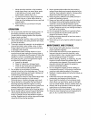
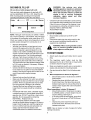
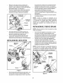
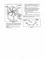
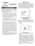
DISCONNECTINGSPARKPLUG
20-oz. Bottle
of Engine Oil
Nuts
Bag
Before proceeding with assembly of your new Yard
Vacuum, disconnect the spark plug wire from the
spark plug and ground onto the retaining post on the
engine. This will prevent accidental starting of the
engine. See Figure 2.
Retaining Post
Lower
Handle
0
Plug Wire
ng
Nuts
Figure 2
Carriage
Screw
ATTACHINGTHE HANDLE
Figure 1
IMPORTANT:This unitis shipped without gasoline or
oil in the engine. After assembly, see OPERATION
section of this manual for proper fuel and engine oil
fill-up.
•
Unfold the upper handle until it aligns with lower
handle. Make sure the rope guide is on the right
side of upper handle. See Figure 1.
•
•
•
•
Securethetwohandles
bytightening
theupper
wingnuts(carriage
boltsmustbeseatedproperly
intothehandle).
Remove
thehairpinclipsfromthehandle
brackets
andremove
thecarriageboltsandwing
nutsfromthelowerhandle.SeeFigure3.
Placethebottomholesinlowerhandleoverthe
pinsonhandlebrackets
andsecurewithhairpin
clips.
Insertcarriage
boltsthroughupperholeinlower
handlefromtheoutsideandsecurewithwing
nuts.
Wing Nuts
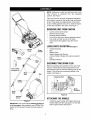
•
•
•
•
Grasp bag handle with one hand and slide
locking rod on mounting bracket with other hand
toward engine. Use the end of mounting bracket
as leverage when sliding the locking rod.
See Figure 4.
Slip bag over the rim of the discharge opening
and release locking rod to secure bag in place.
Snap bag clip to the top of the lower handle.
Place the lower straps on the bag over the top of
lower handle, hooking them on the studs.
NOTE: The bag/chute switch button attached to the
mounting bracket must be fully depressed by the tip
of front tab on bag handle when securing the bag or
engine will not start.
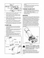
ATTACHINGTHE BLOWERCHUTE
Figure 3
Loosen the wing nut that secures the rope guide
to the right side of upper handle.
Pull the starter rope out of the engine slowly and
slip the starter rope into the rope guide. Tighten
the wing nut.
ATTACHINGTHE BAG
NOTE: The bag must be removed before installing
the blower chute.
•
Grasp blower chute with one hand and slide
locking rod on mounting bracket with other hand
toward engine. Use the end of mounting bracket
as leverage when sliding the locking rod.
See Figure 5.
•
Slip blower chute over rim of discharge opening
and release locking rod to secure chute in
place.
•
Raise the nozzle height to the highest setting
when using the blower chute. Refer to nozzle
height adjustment in the ADJUSTMENT section.
NOTE: The bag/chute switch button attached to the
mounting bracket must be fully depressed by the tip
of front tab on the blower chute or engine will not
start.
Bag Handle
\
Blower
Stud
Front
Tab
Rod
Figure 5
Figure 4
Locking
Rod
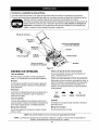
Know Your Yard Vacuum
Read this operator's manual and safety rules before operating your Yard Vacuum. Compare the illustrations
below with your equipment to familiarize yourself with the location of various controls and adjustments. Save
this manual for future reference.
The operation of any Yard Vacuum can result in foreign objects being thrown intothe eyes,
which can result in severe eye damage. Always wear safety glasses, provided with the
Yard Vacuum, for operating this equipment or while performing any adjustments or repairs on
it.
Blower
Starter
Handle
Bag
Throttle Control/
Choke Lever
Primer
Plug Wire
Chute
Nozzle
Nozzle Height
Adjustment Lever
Figure 6
OPERMINGCONTROLS(SeeFigure6)
Nozzle Height Adjustment Lever
Chipper Chute
Used to adjust the nozzle ground clearance ranging
from 5/8" to 4 1/8".
Allows twigs and small branches up to 1 1/2" in
diameter to be fed into the impeller for chipping.
Nozzle
Yard waste such as leaves and pine needles can be
vacuumed up through the nozzle for shredding.
Throttle Control / Choke Lever
This single lever controls the engine speed, stop
function, and the choke of the carburetor. Through
four separate positions on the lever from left to right,
the operation is as follows:
Bag
4P
Collects shredded material fed in through the chipper
chute or vacuumed in through the nozzle.
Blower Chute
When attached to unit, the blower chute is used to
blow or scatter yard waste such as leaves, pine
needle, or small twigs across yard.
Engine
Off
Slow/
Idle
Start/
Run
Choke
Primer
The primer is used to assist in cold starting an engine.
Starter Handle
Bag Handle
Used to grasp bag in order to assist in attaching,
removing, and emptying bag.
Used to start the engine.
Meets ANSI safety standards
Craftsman Yard Vacuums conform to the safety standard of the American National Standards Institute (ANSI).
WARNING:
Use extreme care when
handling gasoline. Gasoline is extremely
flammable and the vapors are explosive.
Never fuel machine indoors or while the
engine is hot or running. Extinguish
cigarettes,
cigars, pipes, and other
sources of ignition.
GASANDOIL FILL-UP
Oil (one 20-oz. bottle shipped with unit)
Only use high quality detergent oil rated with API
service classification SF, SG, or SH. Select the oil's
SAE viscosity grade according to the expected
operating temperature. Follow the chart below.
Colder
--"--_
5W30
32°F
,y_'_ Warmer
Check the fuel level periodically to avoid running
out of gasoline while operating the Yard Vacuum.
If the unit runs out of gas as it is chipping, it may
be necessary to unclog the unit before it can be
restarted. Refer to SERVICE AND
ADJUSTMENT section.
SAE 30
Oil Viscosity Chart
TO STOPENGINE
NOTE: Although multi-viscosity
oils (5W30, 10W30,
etc.) improve starting in cold weather, they will result
in increased oil consumption
when used above 32°F.
Check your engine oil level more frequently to avoid
possible engine damage from running low on oil.
Remove oil fill dipstick.
With the Yard Vacuum on level ground, use a
funnel to fill engine with oil to FULL mark on
dipstick. Capacity is approximately 20 oz. Be
careful not to overfill. Overfilling will cause the
engine to smoke profusely and will result in poor
engine performance. The oil bottle packaged
with your Yard Vacuum contains 20 oz. of oil.
•
Check the oil level making certain not to rub the
dipstick along the inside walls of the oil fill tube.
This would result in a false dipstick reading. Refill
to FULL mark on dipstick, if necessary. Replace
dipstick and tighten.
•
Check oil level three times prior to starting engine
to be certain you've gotten an accurate dipstick
reading. Running the engine with too little oil can
result in permanent engine damage.
Gasoline
•
•
Move throttle control lever to STOP or OFF
position.
Disconnect spark plug wire and ground it to the
post to prevent accidental starting while the
equipment is unattended.
•
•
•
•
•
•
Remove fuel cap from the fuel tank.
Make sure the container from which you will pour
the gasoline is clean and free from rust or foreign
particles. Never use gasoline that may be stale
from long periods of storage in its container.
Gasoline that has been sitting for any period
longer than four weeks should be considered
stale.
Fill fuel tank with clean, fresh, unleaded regular,
unleaded premium or reformulated automotive
gasoline only. DO NOT use Ethyl or high octane
gasoline. Do not use gasoline containing
METHANOL. Replace fuel cap.
To avoid engine problems, the fuel system
should be emptied before storage for 30 days or
longer. Drain the gas tank, start the engine and
let it run until the fuel lines and carburetor are
empty. Use fresh fuel next season. See
STORAGE section for additional information.
lever, be careful
heatedthrottle
surfaces
and
WARNING:
When of
moving
control
sharp edges on muffler guard.
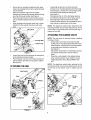
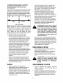
TO STARTENGINE
1.
Attach spark plug wire and rubber boot to spark
plug.
2.
The bag/chute switch button must be fully
depressed by the tip of front tab on bag handle
or blower chute for engine to start.
3.
Make sure bag/chute switch wire is connected to
engine and grounded to mounting bracket.
4.
Gas tank should be filled 3/4 to full before starting.
5.
When temperature is above 32 degrees F:
•
Move throttle control / choke level to START/
RUN position.
•
Depress the primer bulb firmly with your
thumb three times. Wait about two seconds
between each push. Do not use the primer to
restart a warm engine after a short shutdown.
See Figure 7.
When temperature is below 32 degrees F:
•
Move throttle control / choke lever on engine
to CHOKE position. (A warm engine may not
require choking.) See Figure 7.
•
If not using choke to start engine, move throttle control / choke lever to START/RUN position.
•
Depress the primer bulb firmly with your
thumb three times. Wait about two seconds
between each push.
NOTE:
starting
See air cleaner
instructions.
on side of engine
for further
•
Throttle Cont_
Choke
Lever
•
.... ___
Primer
_
F
J
_
I P= Lf_!_l
•
Compress bag opening and fold inner flap over
opening.
Fold outer flap over inner flap and insert buttons
on the bag through metal outlets.
Twist the buttons to lock bag.
_--JI
TO REMOVEBLOWERCHUTE
•
Figure 7
6.
Standing behind the unit, grasp starter handle
and pull rope out until you feel a drag.
7.
Pull the rope with a rapid, continuous, full arm
stroke. Keep a firm grip on the starter handle.
Let the rope rewind slowly.
8.
Repeat, if necessary, until engine starts. When
engine starts, move throttle/choke lever gradually to START/RUN position.
9.
If engine falters, move control lever to CHOKE
position, then back to START/RUN position.
10. ALWAYS keep the throttle control in the START/
RUN position when operating the Yard Vacuum.
TO EMPTYBAG
•
•
•
•
•
Unhook bag straps from the lower handle and
unsnap bag clip from top of the lower handle.
See Figure 8.
Grasp bag handle with one hand and pull lock rod
on mounting bracket with other hand toward
engine to release.
Remove bag from over the rim of the discharge
opening. Refer to Figure 4.
Twist the two buttons on the back of the bag to
unlock and empty contents. See Figure 8.
Hold bag handle and bag clip while emptying the
contents.
•
Grasp blower chute with one hand and pull lock
rod on mounting bracket with other hand toward
engine to release. Refer to Figure 5.
Remove blower chute from over the rim of the
discharge opening.
OPERATION
Place both hands on top of upper handle to push unit
over yard waste. Yard waste such as leaves and pine
needles are vacuumed up through the nozzle and
shredded by the flail blades on the impeller assembly
and discharged into catcher bag or through blower
chute. Do not attempt to shred or chip any material
other than vegetation found in a normal yard (i.e.
branches, leaves, twigs, etc.). Avoid fibrous plants
such as tomato vines until they are thoroughly dried
out. Material such as stalks or heavy branches up to 1
1/2" in diameter may be fed into the chipper chute.
See Figure 9.
Nozzle
Inner Flap
Bag Handle
Bag
Cli
Chi
Figure 9
chip,
or vacuum
than
WARNING:
Do any
not material
attempt larger
to shred,
specified
on the machine
or in this
manual.
Personal
injury or damage to
the machine could result.
Stra
IMPORTANT:The flail screen located inside the
Figure 8
housing in the discharge area. If the flail screen
becomes clogged, stop engine and remove and clean
as instructed in the SERVICE AND ADJUSTMENT
section.
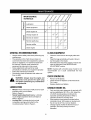
MAINTENANCE
SCHEDULE
_
_o_
_
,_
_¢_ _
h-
o
Lubrication
_
0
Clean equipment
_
<_
Check engine oil
,,,
Change engine oil
_
_
Z
Service air cleaner
Z
"'
Service spark plug
_
Service muffler
Clean engine
<_
GENERALRECOMMENDATIONS
CLEANEQUIPMENT
•
•
•
•
•
•
Always observe safety rules when performing any
maintenance.
The warranty on this Yard Vacuum does not
cover items that have been subjected to operator
abuse or negligence. To receive full value from
the warranty, operator must maintain the
equipment as instructed in this manual.
Some adjustments will need to be made
periodically to maintain your equipment properly.
Follow the maintenance schedule.
Periodically check all fasteners and make sure
they are tight.
•
•
system.
CHECKENGINE01L
•
•
•
LUBRICATION
•
•
Wash the bag periodically with water. Allow to
dry thoroughly in the shade.
If the flail screen becomes clogged, remove and
clean as instructedin the SERVICE AND
ADJUSTMENT section.
NOTE: Cleaning with a forceful spray of water is not
recommended as it could contaminate the fuel
WARNING:
Always stop the engine and
disconnect
and ground the spark plug
wire before performing any maintenance
or adjustments.
•
Clean the Yard Vacuum thoroughly after each
use.
Remove oil fill dipstick.
Check oil level on dipstick. Level should be at
FULL mark.
Replace dipstick and tighten.
CHANGEENGINEOIL
Wheels- Place a few drops of SAE 30 oil on each
shoulder screw once a season.
•
Refer to Figure 6.
Nozzle height adjustment levers- Lubricate
nozzle height adjustment levers with light oil.
Refer to Figure 6.
Locking Rod- Lubricate the lock rod and
compression springs which attach to the
mounting bracket. Refer to Figure 4.
•
•
10
Only use high quality detergent oil rated with API
service classification SF, SG, or SH. Select the
oil's SAE viscosity grade according to the
expected operating temperature. Refer to
operation section for viscosity chart.
Stop engine and wait several minutes before
checking oil level. With engine on level ground,
the oil must be to FULL mark on dipstick.
Change engine oil after the first five hours of
operation, and every twenty-five hours
thereafter.
TO DRAINOIL
SERVICESPARKPLUG
Drain oil while engine is warm. Followthe instructions
given below.
•
•
•
•
•
•
Drain the gas tank, start the engine and let it run
until the fuel line and carburetor are empty.
Remove oil fill dipstick.
Tip unit on its side to drain through the oil fill tube.
When engine is drained of all oil, refill with
approximately 20 oz. of fresh oil. Refer to Gas
And Oil Fill-up in OPERATION section.
Replace dipstick.
Clean the spark plug and reset the gap to .030" at
least once a season or every 50 hours of
operation. See Figure 10. Spark plug
replacement is recommended at the start of each
season. Refer to engine parts list for correct
spark plug type.
NOTE: Do not sandblast spark plug. Spark plug
should be cleaned by scraping or wire brushing and
washing with a commercial solvent.
.030" Feeler Gau
SERVICEAIRCLEANER
The air cleaner prevents damaging dirt, dust, etc.,
from entering the carburetor and being forced into the
engine and is important to engine life and
performance. The air cleaner consists of a foam filter.
Never run the engine without an air cleaner
completely assembled.
To ServiceAir Cleaner:
•
•
•
•
•
•
Figure 10
Remove foam filter from plastic housing on top of
engine.
Wash in water and detergent solution, and
squeeze (do not twist) until all dirt is removed.
Rinse thoroughly in clear water.
Wrap in a clean cloth and squeeze (do not twist)
until completely dry, or allow to air dry.
Saturate with engine oil and squeeze to distribute
oil and remove excess oil.
Replace foam filter in plastic housing
SERVICEMUFFLER
•
•
Inspect muffler periodically, and replace if
necessary.
If your engine is equipped with a spark arrester
screen assembly, remove after every 50 hours of
use for cleaning and inspection. Replace if
damaged.
Vacuum
without
muffler
or tamper
with
WARNING:
Do anot
operate
the Yard
the exhaust system. Damaged mufflers
or spark arresters could create a fire
hazard.
NOTE: If the foam filter is torn or damaged in any
way, replace it.
muffler and WARNING:
nearby areas
may exceed
WARNING:
Temperature
of
150 ° F(65°C). Avoid these areas.
CLEANENGINE
•
•
11
Clean engine by removing dirt and debris with a
cloth or brush.
Frequently remove grass clippings, dirt, and
debris from cooling fins, air intake screen, levers,
and linkage. This will help ensure adequate
cooling and engine speed.
nearest Sears Service Center for repair and adjustment.
adjustment Do
to not
theat unit
without
WARNING:
any time
make first
any
stopping
engine
and
disconnecting
spark plug wire.
WARNING:
Do not attempt to alter the
engine
speed by tampering
with the
engine's
governor
linkage.
Doing so
could result in serious personal injury
and damage to the engine. The engine
RPM has been set at the factory.
NOZZLEHEIGHTADJUSTMENT
The nozzle can be adjusted to any of five positions,
ranging from 5/8" to 4 1/8" ground clearance. The
nozzle height has to be adjusted according to the
conditions. Move the height adjustment levers
forward or backward to adjust the nozzle upward or
downward. It may be necessary to apply slight
pressure to lower handle assembly, when shifting
adjustment levers. See Figure 11.
REMOVINGTHE FLAILSCREEN
If the discharge area becomes clogged, remove the
flail screen and clean area as follows.
•
NOTE: In general, raise the nozzle height to vacuum
a thick layer of leaves or to operate with the blower
chute. Lower the nozzle height for smoother surfaces.
•
•
Stop the engine. Make certain the chipper
shredder vacuum has come to a complete stop.
Disconnect and ground the spark plug wire
before unclogging the discharge chute.
Remove the vacuum bag or blower chute from
the unit as instructed in the OPERATION section
to obtain access to flail screen. See Figure 12.
-lex Screw & Flat Washer
REAR VIEW
Height
Adjustment
Lever
Figure 12
Remove hex screw on right side of unitthat
attaches to the flail screen. See Figure 13.
Figure 11
CARBURETOR
ADJUSTMENT
carburetor) are made to the engine
WARNING: If any adjustments (e.g.
while the engine is running, keep clear
of all moving parts. Be careful of heated
surfaces and muffler.
The carburetor has been pre-set at the factory and
should not require adjustment. If your engine does
not operate properly due to suspected carburetor
problems, take your Yard Vacuum to a Sears Service
Center for repair and adjustment.
Remove
Hex Screw
Figure 13
ENGINESPEED
•
The engine speed on your Yard Vacuum has been
set at the factory. Do not attempt to increase the
engine RPM. If you think that the engine is running
too fast or too slow, take your Yard Vacuum to the
•
12
Remove hex screw and flat washer on top of rear
housing near mounting bracket and the lock nut
that secures flail screen. See Figure 12.
Remove and clean the screen by scraping or
washing with water. Reinstall the screen.
SHARPENINGORREPLACINGCHIPPER
BLADE
•
Because the engine on this unit has a tapered
crankshaft, a special impeller removal tool (part
number 753-0900) is required to remove the impeller
assembly. For further assistance, contact your Sears
Service Center.
•
Remove lock nut that secures flail screen to the
lower housing. The flail screen does not have to
be removed. Refer to Figure 12.
Remove the hex bolt, lock washer, and flat
washer that secure the impeller assembly to the
crankshaft. See Figure 16.
Upper
NOTE: When tipping the unit, empty the fuel tank and
keep engine spark plug side up.
•
•
•
Disconnect and ground the spark plug wire.
Remove the front hubcaps, lock nuts, front
wheels, and wave washers that attach to the pivot
arm assemblies. See Figure 14.
Remove the shoulder screws and bell washers
that go through the pivot arms and height bracket
adjusters to the front support brace.
Flail
Blade
BOTTOM VIEW
Figure 16
Arm Assembly
Bell Washer
•
Washer
Ht
•
Height Adjustment
Bracket
Shoulder
Screw
•
Lock Nut
Figure 14
•
•
Remove the three screws on the upper housing
that secure the nozzle cover and the nine screws
that secure the lower housing to the upper
housing. See Figure 15.
•
Apply lubricant to the threads of impeller removal
tool and then thread the tool into the crankshaft.
Stop when the impeller assembly can move on
the crankshaft.
Remove the impeller assembly from the
crankshaft. Unthread the impeller removal tool
from the impeller assembly.
Remove the chipper blade using a 3/16" allen
wrench on the outside of the blade and 1/2"
wrench on the underside of impeller assembly.
Replace or sharpen chipper blade.
When sharpening blade, protect hands by using
gloves and follow the original angle of grind.
Reassemble by performing the previous steps in
reverse order.
• Tighten blade screws to 210 - 250 in-lbs.
• Tighten impeller bolt to 375 - 425 in-lbs.
Housing
NOTE: Make certain chipper blade is reassembled
with the sharp edge facing upward. See Figure 17.
Screw_
Fl_:,
....
_Chipper
- _
Lower Housing
Screws
Screws
BI
_
_1] _
Figure 15
Figure 17
13
_lmpeller
Assembly
NOTE: Fuel stabilizer is an acceptable alternative in
minimizing the formation of fuel gum deposits during
storage.
Prepare your Craftsman Yard Vacuum for storage at
the end of the season or if the unit will not be used for
30 days or longer. A yearly check-up by your local
Sears Service Center is a good way to ensure that the
unit runs properly next season.
•
Add stabilizer to gasoline in fuel tank or storage
container.
•
Always follow the mix ratio found on stabilizer
container.
•
Run engine at least 10 minutes after adding
stabilizer to allow the stabilizer to reach the
carburetor.
•
Do not drain the gas tank and carburetor if using
fuel stabilizer. Drain all the oil from the
crankcase (this should be done after the engine
has been operated and is still warm) and refill the
crankcase with fresh oil.
If you have drained the fuel tank, protect the inside of
the engine as follows:
YardVacuum
•
•
•
•
Clean the equipment thoroughly.
Wipe equipment with an oiled rag to prevent rust.
Use a light oil or silicone to wipe.
Service the engine following instructions below.
Store unit in a clean, dry area. Do not store next to
corrosive materials such as fertilizer.
Engine
IMPORTANT:It is important to prevent gum deposits
from forming in essential fuel system parts such as
the carburetor, fuel filter, fuel hose, or tank during
storage. Also, alcohol blended fuels (called gasohol or
using ethanol or methanol) can attract moisture which
leads to separation and formation of acids during
storage. Acidic gas can damage the fuel system of an
engine while in storage.
•
•
Other
To avoid engine problems, the fuel system should be
emptied before storage of 30 days or longer. Follow
these instruction:
•
Drain the fuel tank.
•
Start the engine and let it run until the fuel lines
and carburetor are empty.
Drain carburetor.
Never use engine or carburetor cleaner products
in the fuel tank or permanent damage may occur.
•
•
Remove spark plug, pour approximately 1/2
ounce (approximately one tablespoon) of engine
oil into cylinder and crank slowly to distribute oil.
Replace spark plug.
•
Do not store gasoline from one season to
another.
•
Replace the gasoline can if it starts to rust. Rust
and/or dirt in the gasoline will cause problems.
Store unit in a clean, dry area. Do not store next
to corrosive materials, such as fertilizer.
•
NOTE: If storing in an unventilated
or metal storage
shed, be certain to rustproof the equipment by coating with a light oil or silicone.
14
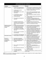
Problem
Possible Cause(s)
Corrective Action
Engine fails to start
1.
Fuel tank empty or stale fuel.
1.
2.
3.
Spark plug wire disconnected.
Cannot pull recoil cord.
2.
3.
4.
5.
6.
Choke not in ON position.
Faulty spark plug.
Safety switch not depressed.
4.
5.
6.
7.
Safety switch wire is not
connected to engine or not
properly grounded.
7.
1.
2.
3.
Spark plug wire loose.
Unit running on CHOKE.
Blocked fuel line or stale fuel.
1.
2.
3.
4.
Water or dirt in fuel system.
4.
5.
6.
Carburetor out of adjustment.
Low engine RPM.
5.
6.
Too much vibration
1.
Loose parts or damaged
impeller.
1.
Stop engine immediately and disconnect spark
plug wire. Have unit serviced by a Sears
Service Center.
Engine overheats
1.
2.
Carburetor not adjusted
Engine oil level low
1.
2.
Contact your Sears Service Center.
Fill crankcase with proper selection of oil.
Unit does not
1.
Discharge
chute clogged.
1.
2.
2.
3.
4.
Foreign object lodged in
impeller.
Low engineRPM.
Vacuum bag is full.
Stop engine immediately and disconnect spark
plug wire. Clean flail screen and inside of
discharge opening. See Maintenance section of
this manual.
Stop engine immediately and disconnect spark
plug wire. Remove lodged object.
Always run engine at full throttle.
Empty bag.
1.
2.
Low engineRPM.
Chipper blade dull.
1.
2.
Loss of power;
operation erratic
discharge
Rate of discharge
slows considerably
or
composition of
discharged material
changes
NOTE: For repairs beyond
the minor adjustments
3.
4.
listed above, please
15
Fill tank with clean, fresh gasoline. Fuel will not
last over thirty days unless a fuel stabilizer is
added.
Connect wire to spark plug.
Obstruction lodged in impeller. Disconnect
spark plug wire and remove lodged object.
Move CHOKE to ON position.
Clean, adjust gap or replace.
Safety switch must be depressed by the front
tab on the bag handle when securing the bag.
Connect safety switch wire to engine connector
and ground to mounting bracket.
Connect and tighten spark plug wire.
Move choke lever to OFF position.
Clean fuel line; fill tank with clean fresh
gasoline. Fuel will not last over thirty days
unless a fuel stabilizer is used.
Disconnect fuel line at carburetor to drain fuel
tank. Refill with fresh fuel.
Contact your Sears Service Center.
Always run engine at full throttle.
Always run engine at full throttle.
Replace chipper blade or see your Sears
Service Center.
contact your local Sears Service
Center.
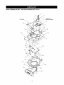
Sears Craftsman
4.5 H.P. Yard Vacuum
Model 247.770110
Ground To
To En("
_Mountlng
12
I
13
I
I
13
15
25
I
I
,31
I
4--32
I
I
I
36
16
Bracket
Sears Craftsman
Ref.
No.
PaN No.
4.5 H.P. Yard Vacuum
Model 247.770110
Ref.
No.
Part Description
Part No.
Part Description
1.
725-1700
Switch Cover
21.
710-1054
Hex Screw 5/16-24 x 1.0
2.
3.
725-3168
710-0224
Safety Switch
Hex Washer Screw #10-16 x .50
22.
23.
781-0490
736-0119
Chpper Blade
Lock Washer 5/16
4.
629-0920
Wire Harness
24.
712-0411
Hex Lock Nut 5/16-24
5.
6.
710-0604A
714-0104
Hex Washer Screw 5/16-18 x .625
Cotter Pin
25.
26.
681-0152
Impeller Assembly
Flail Blade
7.
738-0264
Flat Washer.330 ID x.630 OD
27.
719-0329
781-0735
8.
732-0962
Compression Spring
28.
711-1401
Mounting Bracket
Lock Rod
29.
30.
715-0166
9.
781-0778A
10.
11.
747-1153
710-3008
12.
681-0122
Hex Cap Screw 5/16-18 x .75
Chpper Chute Assembly
31.
32.
13.
14.
726-0454
736-0807
U-Chp Lock Nut 5/16-18
External Lock Washer 5/16
15.
710-0502A
18.
710-0989
17.
18.
710-3195
710-3025
19.
710-0604A
Hex Cap Screw 5/16-18 x 4.5
Hex Cap Screw 5/16-18 x .625
Hex Washer Screw 5/16-18 x .625
20.
781-1085
Upper Housmg
736-0247
736-0217
Pin Clip
Clevis Pin
Spiral Pin
Flat Washer.375 ID x 1.25 OD
Lock Washer 3/8
710-0818
Hex Cap Screw 3/8-24 x 2.0
33.
34.
681-0154
710-3038
Screen Assembly
Hex Cap Screw 5/16-18 x .875
Hex Washer Screw 3/8-16 x 1.25
35.
781-0721A
Screw #12-16 x 1.0
36.
712-3004A
Lower Housing
Lock Nut 5/16-18
37.
38.
39.
731-1905
Nozzle Cover
712-0158
731-1613
Lock Nut 5/16-18
Safety Switch Cover
NOTE: For painted parts, please refer to the list of color codes below. Please add the apphcable color code, wherever needed,
to the part number to order a replacement part. For instance, if a part, numbered 700-xxxx, is painted polo green, the part number to order would be 700-xxxx-0689.
Polo Green:
0689
Oyster Grey:
0662
Powder Black:
0637
17
Sears Craftsman
4.5 H.P. Yard Vacuum
Model 247.770110
2
3
35
9
11
10
13
12
15
14
\
16
36
17
,/
19
37
14
12
28
25
27
20
/
31
18
Sears Craftsman
Ref.
No.
Part No.
4.5 H.P. Yard Vacuum
Model 247.770110
Ref.
No.
Part Description
Part Description
Part No.
1.
720-0295
Foam Grip
19.
734-1992
Wheel 9 x 2
2.
3.
749-0438D
720-0279
Upper Handle
Knob
20.
21.
738-1015
731-0981A
Shoulder Screw 3/8-16
4.
710-1205
720-0276
22.
23.
781-0725A
781-0785
Front Wheel Support Brace
5.
Eye Bolt
Handle Knob 5/16-18
6.
7.
710-1174
749-0907B
Carriage Bolt
Lower Handle
24.
25.
738-1185
741-0751
8.
664-0094
9.
711-1293
Bag Assembly
Studs
26.
27.
682-0113
736-0232
Pivot Arm Assembly
Wave Washer .531 ID x .781 OD
10.
11.
712-0397
710-0703
Wing Nut 1/4-20
Carriage Screw 1/4-20 x .75
28.
29.
720-0426
732-1026
Height Adjustment Knob
12.
726-0453
Lock U-Clip Nut 3/8-16
30.
736-0741
Spring Lever
Bell Washer .760 ID x .25OD
13.
781-0777
Rear Wheel Support Brace
31.
738-1173
Shoulder Screw .750 ID x .625 OD
14.
15.
712-3004A
714-0104
Flange Lock Nut 5/16-18
Cotter Pin
32.
33.
734-1978
712-0431
Wheel 8 x 2
16.
681-0155
Handle Bracket Ass"y LH
34.
736-0314
681-0156
Hndle Brkt Ass"y RH (Not Shown)
Hex Cap Screw 5/16-18 x .625
Bell Washer.401 ID x.870 OD
35.
36.
37.
631-0090
764-0631
631-0083
17.
18.
710-3025
736-0105
Hubcap
Height Adjustment Bracket
Stud 5/16-18.56 x .75
Height Adjustment Bearing
Flange Lock Nut 3/8-16
Thrust Washer .375 ID x .70 OD
Blower Chute Assembly
Bag
Chute Assembly
NOTE: For painted parts, please refer to the list of color codes below. Please add the applicable color code, wherever needed,
to the part number to order a replacement part. For instance, if a part, numbered 700-xxxx, is painted polo green, the part number to order would be 700-xxxx-0689.
Polo Green:
0689
Oyster Grey:
0662
Powder Black:
0637
19
Sears Craftsman 4.5 H.P. Engine Model No. 143.004500
For Yard Vacuum Model 247.770110
L
19
151A
310
21%
J
07
72A
380
79
45
] 74
_305
22
182
185
)7
260
73
75
20
72
Sears Craftsman 4.5 H.P. Engine Model No. 143.004500
For Yard Vacuum Model 247.770110
Ref.
No.
1.
2.
6.
7.
12A.
14.
15.
16.
17.
18.
19.
20.
30.
40.
41.
42.
43.
45.
46.
48.
50.
52.
69.
70.
72.
72A.
73.
75.
80.
81.
82.
83.
86.
89.
90.
92.
93.
100.
101.
103.
104.
110.
110A.
119.
120.
125.
126.
130.
135.
150.
151.
151A.
Part No.
37266
26727
33734
37247
36558
28277
30589
34839A
31335
651018
36281
32600
37527
40027
40028
40025
40026
40006
40007
20381
36777
32610A
27241
37460
29914
35261
36249B
30572
28534
28833
27897
30574A
30590A
30591
30588A
650488
611004
611112
650815
650816
34443B
610118
651007
37480
37574
37331
36787
36825
37288
37289
6021A
35395
31672
31673
40017
Ref.
No.
Part Description
Cylinder
Dowel Pin
Breather Element
Breather Ass'y
Breather Cover & Tube
Washer
Governor Rod
Governor Lever
Governor Lever Clamp
Torx Screw 8-32 x 19/64"
Extension Spring
Oil Seal
Crankshaft
Piston, Pin & Ring Set (Std)
Piston, Pin & Ring Set (.010" OS)
Piston & Pin Ass'y (Std)
Piston & Pin Ass'y (.010" OS)
R_ng Set (Std)
Ring Set (.010" OS)
Piston Pin Retaining Ring
Connecting Rod Ass'y
Connecting Rod Bolt
Valve Lifter
Camshaft
Oil Pump Ass'y
Mounting Flange Gasket
Mounting Flange
Oil Drain Plug
Oil Drain Plug
Drain Plug Gasket
Oil Seal
Governor Shaft
Washer
Governor Gear Ass'y
Governor Spool
Screw 1/4-20 x 1-1/4
Flywheel Key
Flywheel
Bell Washer
Flywheel Nut
Solid State Ignition
Spark Plug Cover
Torx Screw 10-24 x 15/16"
Cam Bushing
Ground Wire
Ground Wire
Cylinder Head Gasket
Cyhnder Head
Exhaust Valve
Intake Valve
Screw 5/16-18 x 1-1/2"
Resistor Spark Plug
Valve Spring
Valve Spring Cap
Intake Valve Seal
169.
172.
174.
178.
179.
182.
184.
185.
186.
200.
203.
204.
206.
207.
209.
215.
223.
224.
238.
239.
240.
245.
245A.
250.
260.
261.
262.
275.
277.
279.
279A.
280.
285.
287.
290.
292.
300.
301.
305.
306.
307.
309.
310.
313.
324.
370A.
370K.
370R.
370S.
380.
390.
400.
416.
417.
900.
21
Part No.
36783
36784
30200
29752
30593
6201
26756
36785
34337
32264A
31342
651029
610973
34336
30200
32410
650451
36786
650806
34338
37115
37116
37117
37118
37151
30200
650831
36790A
650988
650737
650902
37171A
35000A
650926
34357
26460
35586
36246
35577
36996
35499
650562
35578
34080
33177
36261
36695
37317
37590
640278
590737
36792B
36085
650821
750856A
Part Description
Valve Cover Gasket
Valve Cover
Screw 10-24 x 9/16"
Nut & Lock Washer 1/4-28
Retainer Clip
Screw 1/4-28 x 7/8"
Carburetor To Intake Pipe Gasket
Intake Pipe
Governor Link
Control Bracket
Compression Spring
Torx Screw 5-40 x 7/16"
Terminal
Throttle Link
Screw 10-24 x 9/16"
Control Knob
Screw 1/4-20 x 1"
Intake Pipe Gasket
Screw 10-32 x 1/2"
Air Cleaner Gasket
Air Cleaner Body
Air Cleaner Filter
Pre-Air Cleaner Filter
A_r Cleaner Cover
Blower Housing
Screw 10-24 x 9/16"
Screw 1/4-20 x 1/2"
Muffler
Screw 1/4-20 x 2-5/16"
Screw 1/4-20 x 1/2"
Screw 10-32 x 7/16"
Heat Sheld
Starter Cup
Screw 8-32 x 21-64"
Fuel Line
Fuel Line Clamp
Fuel Tank
Fuel Cap
Oil Fill Tube
O-Ring
O-Ring
Screw 10-32 x 1/2"
Dipstick
Spacer
Terminal
Lubrication Label
Starter Label
Warning Label
Instruction / Primer Label
Carburetor
Rewind Starter
Gasket Set
Spark Arrestor
Screw 10-32 x 1/2"
Short Block
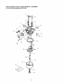
Sears Craftsman 4.5 H.P. Engine Model No. 143.004500
For Yard Vacuum Model 247.770110
I
t
®
/
20A
29
2O
I
I
.3O
_:)=
37
22
Sears Craftsman 4.5 H.P. Engine Model No. 143.004500
For Yard Vacuum Model 247.770110
Ref.
No.
Part No.
1.
2.
631615
631767
3.
640278
4.
631184
5.
6.
Ref.
No.
Part Description
Part Description
Part No.
Float Bowl
Float Shaft
Throttle Shaft & Lever Assembly
25.
631867
Throttle Return Spring
Carburetor
27.
28.
631024
632019
29.
30.
631028
631021
Float Bowl O-Ring
631183
640070
Dust Seal Washer
Dust Seal
Throttle Shutter
31.
631022
7.
650506
Shutter Screw
35.
640259
Spring Clip
Primer Bulb
10.
11.
630973
632045
Choke Shaft & Lever Assembly
36.
632735
Main Nozzle Tube
640150
Choke Return Spring
Choke Shutter
37.
40.
632547
640050
Main Nozzle Tube O-Ring
14.
16.
631807
Fuel Fitting
44.
27110A
High Speed Bowl Nut
Bowl Nut Washer
17.
651025
Idle Speed Screw
47.
630748
Idle Mixture Well Plug
18.
20.
630766
640027
Tension Spring
Idle Restrictor Screw
48.
60.
631027
632760
Atmospheric Vent Plug
Repair Kit
20A.
640053
Idle Jet Cap
23
Float
Inlet Needle, Seat, & Clip
Sears Craftsman 4.5 H.P. Engine Model No. 143.004500
For Yard Vacuum Model 247.770110
Ref.
No.
1.
Spring Pin
Washer
590696
Retainer
Washer
5.
590601
590697
6.
590698
Brake Spring
Starter Dog
3.
4.
/
7_....__._.1..
_
_1_._,______
7
Part Description
590599A
590600
2.
13
Part No.
7.
590699
Dog Spring
8.
9.
590700
590694
Pulley & Rewind Spring Ass'y
Recod Starter
11.
590695
Starter Housing Ass'y
12.
590535
13.
590701
Starter Rope
Starter Handle
14--_.
12
Ref.
No.
Part No.
Part Description
1.
590737
Rewind Starter
3.
6.
590740
590616
Retainer
7.
590617
Dog Spring
8.
11.
590618A
590687A
Pulley & Rewind Spring Ass'y
12.
590535
13.
14.
590701
Starter Housing Ass'y
Starter Rope
Starter Handle
590760
Spring Clip
Starter Dog
13
[._',
6..1/_,,i_
'31
24
/r!
/3
Contenido
Pagina
Contenido
Pagina
Garantia
25
Servicio y ajustes
35
Seguridad
26
Almacenamiento
38
Montaje
28
Localizaci6n de averias
39
Operaci6n
30
Lista de repuestos
16
Mantenimiento
33
Garantia de un a_o sobre la aspiradora
para jardines Craftsman
Por un periodo de un a_o a partir de la fecha de compra, Sears reparara gratis cualquier defecto en el material o
fabricaci6n de esta aspiradora para jardines Craftsman, siempre y cuando haya sido mantenida, lubricada y
afinada de acuerdo alas instrucciones de manejo y mantenimiento dadas en el manual del operador.
Esta garantia excluye las cuchillas, cuchillas astilladoras, flagelos, filtros de aire, bujias, recolectores y
neumaticos, consideradas piezas consumibles que se gastan durante el uso normal.
LA GARANTIA DE SERVICIO ESTA DISPONIBLE
PONIENDOSE
EN CONTACTO
CON EL CENTRO DE
SERVICIO SEARS MAS CERCANO EN EE.UU. ESTA GARANTIA TIENE VALIDEZ SOLAMENTE
MIENTRAS
EL PRODUCTO
SE ENCUENTRA
EN USO EN LOS ESTADOS UNIDOS.
Esta garantia le da derechos legales especificos,
y usted puede tener otros derechos los cuales varian
estado a otro.
Sears, Roebuck and Co., D/817WA, Hoffman Estates, II 60179
ASPIRADORA
de un
PARA JARDINES
ATENCION:
Antes de usar este producto, lea este manual
las reglas de seguridad e instrucciones
de manejo,
ESPECIFICACIONES
y respete
todas
DEL PRODUCTO
Potencia:
4.5 caballos de fuerza
Nl3mero de modelo ......... .2...4..7.;..7..7..0..1..1...0.
.............
Tipo de aceite de motor
SAE 30
NQmero de serie ..................................................
Capacidad
de aceite de motor
20 onzas
Capacidad
de combustible:
1 1/2 cuartos de gal6n
Chamnion RJ-19LM
Buiia
Distancia
Fecha de compra .................................................
entre electrodos
25
Anote el nQmero de serie y la fecha de compra y
guardelos en un lugar seguro para usar de
referencia en el futuro.
ADVERTENCIA:
Este simbolo indica instrucciones de seguridad muy importantes las que, si no
se siguen, podrian poner en peligro la seguridad personal y/o causar dahos fisicos. Antes de
intentar manejar esta aspiradora para jardines, se debe leer y seguir todas las instrucciones que
aparecen en este manual. Si no se cumplen estas instrucciones se corre el riesgo de sufrir lesiones.
Cuando en el manual aparece este simbolo, respetar su advertencia.
ADVERTENCIA:
El gas de escape emitido por el motor de esta m_quina contiene componentes
quimicos queen
el Estado de California son considerados como causantes de c_ncer, defectos de
nacimiento u otros daSos a los 5rganos de la reproducciSn.
ADVERTENCIA:
La aspiradora para jardines fue fabricada para ser manejada de acuerdo alas reglas
de seguridad descritas en este manual. Como sucede con cualquier tipo de equipo motorizado, el descuido
o error de parte del operador puede tener como resultado graves lesiones. Esta m_quina es capaz de
amputar dedos y manos y lanzar objetos con fuerza. Si no se siguen las instrucciones de seguridad
siguientes se est_ expuesto a sufrir graves lesiones o la muerte.
OPERACIONENGENERAL
atrapados en las piezas en movimiento. Nunca
manejar la m_quina descalzo, con sandalias o
zapatillas. Ponerse guantes para introducir el
material en el tubo de triturado.
• Leer
todo
este
manual
del
operador
cuidadosamente
antes de intentar armar
la
m_quina. Leer, comprender y seguir todas las
instrucciones que se encuentran en la m_quina y
en el manual (manuales) antes de manejarla.
Aprender
completamente
el manejo de los
controles y el uso correcto de la m_quina antes de
manejarla. Guardar este manual en un lugar
seguro para usarlo como un libro de consulta en el
futuro y cuando sea necesario pedir piezas de
repuesto.
• La aspiradora para jardines es una herramienta
muy potente, no es un juguete. Por Io tanto, actuar
con sumo cuidado en todo momento. La m_quina
fue diseSada para astillar, triturar, aspirar y soplar
(cuando est_ equipada
con el accesorio)
la
vegetaciSn encontrada en un jardin o patio normal.
No se debe usar para ningt)n otro propSsito.
• No dejar nunca que niSos menores de 16 aSos de
edad manejen esta m_quina. Los niSos mayores
de 16 aSos siempre deben manejarla bajo la
supervisiSn
de un adulto.
Solamente
debe
permitirseles manejar esta m_quina alas personas
responsables que conozcan bien estas reglas de
seguridad de manejo.
• Mantener el lugar de trabajo despejado
de
personas, especialmente niSos pequeSos. Apagar
el motor cuando se encuentren cerca de la
m_quina.
• Cuando se est_ introduciendo material a este
equipo, tener mucho cuidado de no incluir pedazos
de metal, rocas, botellas, latas u otros objetos
extraSos. Se podria causar lesiones personales o
daSar la m_quina.
• Siempre usar anteojos o gafas de seguridad,
durante el manejo y mientras se hacen ajustes o
reparaciones,
para protegerse los ojos contra
objetos extraSos que puedan ser lanzados por la
m_quina.
• Usar zapatos de trabajo gruesos y con suela
_spera, y pantalones y camisa bien ceSidos. Se
recomienda usar camisas y pantalones que cubran
los brazos y las piernas, y zapatos con puntas de
acero. No usar ropa suelta o joyas, y atarse el
cabello m_s arriba de los hombros. Pueden quedar
• No manejar la m_quina si se ha ingerido alcohol o
drogas.
• No tratar de alcanzar m_s lejos de Io normal.
Mantener bien apoyado los pies y buen equilibrio
en todo momento.
• No poner nunca las manos ni ninguna parte del
cuerpo o indumentaria cerca de las piezas que
est_n girando. Siempre mantenerse alejado de las
bocas de descarga. Nunca meter las manos ni
ninguna parte del cuero o indumentaria en la
boquilla, tubo de triturar o boca de descarga, pues
el rotor giratorio puede causar graves lesiones.
• Si por cualquier razSn es necesario desatascar la
toma de alimentaciSn o la boca de descarga o
inspeccionar o reparar alguna pieza de la m_quina
en una parte donde una pieza en movimiento
podria quedar en contacto con el cuerpo o
indumentaria, apagar el motor, esperar hasta que
se enfrie, desconectar el cable de la bujia y
apartarlo de la bujia antes de intentar desatascar,
inspeccionar o reparar.
• Nunca manejar la m_quina sin que tenga instalado
el recolector de la aspiradora o, si est_ equipada
con tubo soplador, bien conectado a la m_quina. El
extremo abierto grande del recolector (bolsa) debe
estar cerrado para impedir que salgan objetos
soplados por la parte trasera del recolector.
• Cuando se trabaje con la funciSn de soplador (esta
m_quina puede tener incluido el accesorio de tubo
de soplado opcional):
• No situarse ni caminar delante de la boca de
descarga del soplador ni apunt_rsela alas
personas, animales, vehiculos, etc. que se
encuentren cerca. Los objetos que salen
lanzados por la boca de descarga puede
causar lesiones personales o daSos a la
propiedad.
• No dirigir la descarga del soplador contra una
pared u otra obstrucciSn vertical. El material
descargado puede rebotar hacia el operador.
• Ajustar la altura de la boquilla de aspiraciSn a
la posiciSn m_s alta para reducir la posibilidad
de que aspiren objetos m_s pesados (por ej.,
26
•
•
•
•
•
•
•
•
piedras,
pedazos
devidrioo demetal)ysean SERVICIO
lanzados
porlabocadedescarga.
AIelevarla
boquillaa la posici6nm_s alta tambi_n
• Tener sumo cuidado cuando se maneje gasolina y
incrementa
la admisi6n
de aireparaIograr
otros combustibles. Son muy inflamables y sus
mejorfuncionamiento
delsoplador.
vapores son explosivos.
No intentarnuncaretiraro vaciarel recolector
• Guardar el combustible
y el aceite en
mientras
el motorest_funcionando.
Apagarel
contenedores aprobados, lejos del calor y
motory esperar
hastaqueel rotorest6detenido
llamas expuestas, y lejos del alcance de los
nifios.
antesde retirarel recolector
(bolsa).El rotor
contin6a
girando
poralgunos
segundos
despu6s
• Revisar el nivel y cargar combustible antes de
deapagar
el motor.Nuncaacercar
ninguna
parte
arrancar el motor. Nunca quitar la tapa del
delcuerpoal _readelrotorsinantesasegurarse
tanque de combustible ni afiadir combustible
dequehaparado
degirar.
mientras el motor est_ funcionando. Siempre
Mantener
todoslosprotectores
y dispositivos
de
dejar que el motor se enfrie por Io menos
seguridad
en su lugaryen buenestadode
durante
dos
minutos
antes
de cargar
funcionamiento.
combustible.
Nodejarquese acumule
material
tratadoenel
• Antes de arrancar el motor, colocar la tapa del
_reade descarga,
puesimpedir_la descarga
tanque de gasolina bien apretada y limpiar con
adecuada.
un trapo la gasolina que pueda haberse
derramado ya que podria causar un incendio o
Cuando
seintroduzca
material
enlaastilladora,
no
explosi6n.
situarseconla carao el cuerpodirectamente
delante
deltubodela astilladora.
Situarse
a un
• Apagar los cigarrillos, cigarros, pipas y otras
lado.Elmaterial
queseest_introduciendo
puede
fuentes de ignici6n.
rebotar
fueradeltubo.
• Nunca cargar combustible en el interior de
Si el mecanismo
decortechoque
conunobjeto
edificios porque pueden acumularse vapores
extrafio
osilam_quina
empieza
a hacer
unruidoo
inflamables en el _rea.
vibraci6n
inusual,
apagar
inmediatamente
elmotor,
• Nunca guardar la m_quina o el contenedor de
desconectar
el cabledelabujiay apartarlo
dela
combustible en interiores donde haya una
bujia.Dejarquelam_quina
separey proceder
de
llama expuesta o chispas, como por ejemplo,
lamanera
siguiente:
un calentador de agua caliente, secadora de
• Buscar
sihaydafio
ropa o un calefactor de gas.
• Reparar
o cambiar
laspiezas
dafiadas.
• No hacer funcionar nunca la m_quina en un lugar
cerrado pues el gas de escape del motor contiene
• Buscar
piezas
flojasy apretarlas
paraasegurar
unbuenfuncionamiento.
mon6xido de carbono, el cual es un gas inodoro,
insipido y mortalmente venenoso.
El silenciador
y el motorse calientan
y puede
• Para reducir el peligro de incendio, mantener el
causar
quemaduras.
Notocarlos.
motor y el silenciador libres de hojas, pasto y otra
No dejarquelas hojasu otrosdesechos
se
acumulaci6n de desechos. Limpiar el combustible y
acumulen
enelsilenciador
delmotor.
Losdesechos
aceite derramado. Dejar que la m_quina se enfrie
pueden
encenderse
ycausar
unincendio.
durante por Io menos 5 minutos antes de guardarla.
Nohacerfuncionar
el motorsi elfiltrodeaireo la
•
Antes de limpiar reparar o inspeccionar, cerciorarse
tapaencima
delatomadeairedelcarburador
no
de que el rotor y todas las piezas m6viles se hayan
est_colocada.
El retirode dichaspiezaspuede
detenido. Desconectar el cable de la bujia y
crearunpeligro
deincendio.
apartarlo de la bujia para impedir el arranque
accidental
del
motor.
No usar
soluciones
inflamables para limpiar el filtro de aire.
• Mantener todas las tuercas, pemos y tomillos
apretados para asegurar que el equipo est_ en
buenas condiciones de funcionamiento.
NINOS
Pueden ocurrir accidentes de tr_gicas consecuencias si el
operador no est_ alerta a la presencia de nifios pequefios.
Los nifios son frecuentemente
atraidos a los lugares
donde se est_ astillando y aspirando hojas, ramas, etc.
Nunca suponer que los nifios van a permanecer en el
lugar donde se les viola 61tima vez.
• No dejar que los nifios se acerquen al lugar de
trabajo y mantenerlos vigilados por un adulto
aparte del operador.
• Estar alerta y apagar el motor si un nifio se
aproxima al lugar.
• Nunca permitir que nifios menores de 16 afios de
edad manejen la aspiradora para jardines.
• Nunca estorbar los dispositivos de seguridad.
Probar su funcionamiento peri6dicamente.
• Despu6s de chocar con un objeto extrafio, apagar
inmediatamente el motor, desconectar el cable de
la bujia y hacer una inspecci6n minuciosa de la
m_quina en busca de alg6n dafio. Reparar el dafio
antes de arrancar el motor y manejar la m_quina.
• No alterar ni estorbar el ajuste del gobernador del
motor. El gobemador controla la velocidad m_xima
segura del motor. El hacer funcionar el motor a
sobrevelocidad es peligroso y se dafiar_ el motor y
las otras piezas m6viles de la m_quina.
• Revisar el recolector (bolsa) de la aspiradora
frecuentemente. Cambiarlo si est_ desgastado o
dafiado.
• Mantener el recolector sin desechos cuando no
est_ en uso.
27
NOTE:
Para
determinar
los
lados
derecho
e
izquierdo
de la aspiradora
para jardines,
situarse
detrbs de la mbquina, en posiciOn de manejarla.
Ver
la figura 1.
La aspiradora para jardines fue armada en la fabrica,
con la excepci6n del manillar, recolector y tubo de
soplado. Estos componentes se envian sueltos en la
caja de cart6n. En la caja tambien se incluyen
anteojos de seguridad y una botella de 20 onzas de
aceite para motor. Ver la figura 1.
DESEMBALAJE
•
•
•
•
Tubo de
•
Manillar
Cortar las esquinas de la caja.
Quite todas las piezas flojas.
Quite el material de embalaje.
Levante la unidad de la parte posterior para
desechar el material de embalaje de la unidad
inferior y de la unidad del rodillo de cart6n.
Controle el cart6n a conciencia para saber si hay
cualquier otra pieza floja.
PIEZASSUELTAS
Ver la figura 1
•
•
•
•
•
•
Guia de
Tuerca de
mariposa
Botella de 20 oz.
aceite para
motor
Tuercas
mariposa
Montaje del manillar
Recolector (bolsa)
Montaje del tubo de soplado
Anteojos de seguridad (no se muestran)
Botella de 20 onzas de aceite para motor
Manual del operador
DESCONEXION
DE LA BUJIA
Antes de comenzar a armar la nueva aspiradora para
jardines, desconectar el cable de la bujia y conectarlo
a tierra en el pilar retenedor en el motor. Esto
impedira el arranque accidental del motor. Ver la
figura 2.
Pilar retenedor
Bolsa
Manillar
inferior
O
O
Tuercas de
mariposa
de bujia
carruaje
Figura 2
INSTALACIONDELMANILLAR
Figura 1
IMPORTANT:Esta maquina sail6 de fabrica sin
gasolina y sin aceite en el motor. Despues de
armada, ver la secci6n OPERAClON en este manual
para informarse sobre el Ilenado de aceite del motor y
el tipo de combustible.
Plegar el manillar superior hasta que quede
alineado con el manillar inferior. Ver la figura 1.
Fijarlo bien apretando las tuercas de mariposa
superiores, las cuales conectan juntos los dos
manillares.
28
•
•
Retirar las chavetas de las escuadras del
manillar y los tornillos de carruaje (cabeza de
hongo y cuello cuadrado) y tuercas de mariposa
del manillar inferior. Ver la figura 3.
Colocar el manillar inferior sobre los pasadores
en las escuadras y fijarlos con las chavetas,
tornillos de carruaje y tuercas de mariposa.
Tuercas de
mariposa
•
•
•
de soporte de montaje como el apalancamiento
deslizando la barra que se cierra. Ver la figura 4.
Deslizar el recolector por encima del borde de la
boca de descarga y soltar la varilla de fijaci6n
para sujetar el recolector en su lugar.
Colocar las correas inferiores del recolector
sobre el manillar inferior, enganchandolas en los
esparragos.
Encajar el clip del recolector en la parte superior
del manillar inferior.
NOTE: Cuando se coloque el recolector en la
m4quina, el botOn interruptor de seguridad adosado
a la escuadra de montaje debe quedar totalmente
oprimido por la lengE_eta delantera ubicada en el
mango del recolector, de Io contrario el motor no
arrancar4.
INSTALACIONDELTUBODE SOPLADO
Figura 3
•
•
En el lado derecho del manillar superior se
encuentra una guia para la cuerda. Aflojar la
tuerca de mariposa que sujeta la guia.
Tirar la cuerda de arranque fuera del motor
lentamente y deslizarla a traves de la guia.
Apretar la tuerca de mariposa. Tolva de Soplador
NOTE: Antes de instalar
retirar el recolector.
•
•
INSTALACIONDELRECOLECTOR
•
Manija de
Bolso
el tubo de soplado
se debe
Asir el tubo de soplado con una mano y, con la
otra mano, tirar de la varilla de fijaci6n en la
escuadra de montaje hacia el motor. Use el final
de soporte de montaje como el apalancamiento
deslizando la barra que se cierra. Ver la figura 5.
Deslizar el tubo de soplado por encima del
borde de la boca de descarga y soltar la varilla
de fijaci6n para sujetar el tubo en su lugar.
Cuando se va a usar el tubo de soplado, elevar la
boquilla a la posici6n mas alta. Ver el ajuste de la
boquilla en la secci6n AJUSTES.
Tachor
NOTE: El botOn interruptor de seguridad adosado a
la escuadra
de montaje
debe quedar
totalmente
oprimido por la lengEleta delantera ubicada en tubo
de soplado, de Io contrario el motor no arrancar4.
Tolva de
)lador
Etiqueta
Delantera
Cierre de
ueta
De
Cierre de
Barra
Figura 4
Asir el mango del recolector con una mano y, con
la otra mano, tirar de la varilla de fijaci6n en la
escuadra de montaje hacia el motor. Use el final
Figura 5
29
/
Barra
Conozca
su aspiradora
para jardines
Lea este manual del operador y las reglas de seguridad antes de manejar su aspiradora para jardines.
Compare las ilustraciones presentadas mas abajo con su equipo para que conozca bien la ubicaci6n de los
distintos controles y ajustes. Guarde este manual para consultarlo en el futuro.
El manejo de cualquier aspiradora para jardines sopladora puede causar el lanzamiento de
objetos extraSos contra los ojos y lesionarlos gravemente. Use siempre los anteojos de
seguridad, suministrados con la aspiradora para jardines Craftsman, para manejar este
equipo o mientras le hace trabajos de ajuste o reparaci6n.
Mango de arran€
Recolector
Palanca de estrangulador/
control del acelerador
Mango del
recolector
Tubo de soplado
Tubo de
astillado--
de bujia
Palanca de ajuste
de altura de la boquilla
Boquilla
Figura 6
CONTROLESDEOPERACION
Palanca de ajuste de altura de la boquilla
Tubo de astillado
Se usa para ajustar la altura entre la boquilla y el
suelo, variando de 5/8" a 4 1/8".
Permite introducir ramillas y ramas pequeSas de
hasta 1-1/2" de diametro en el rotor para astillarlas.
Boquilla
Los desechos del jardin tal como hojas y agujas de
pino pueden aspirarse a traves de la boquilla para
luego triturarlos.
Recolector
Junta todo el material triturado que fue introducido a
traves del tubo de astillado o que fue aspirado a
traves de la boquilla.
Tubo de soplado
Cuando esta instalado en la maquina, este tubo se
usa para soplar o esparcir los desechos del jardin tal
como hojas, agujas de pino o ramillas pequeSas.
Palanca de estrangulador/control
Motor
apagado
Lento
R_pido
Estrangulador
Cebador
El cebador se usa para ayudar durante el arranque
del motor en frio.
Mango del recolector
Mango de arranque
Se usa para agarrar el recolector y poderlo instalar,
retirar y vaciar.
Se usa para arrancar el motor.
NOTE: De conformidad
del acelerador
Esta palanca t_nica controla la velocidad del motor, la
funci6n de parada y el estrangulador del carburador.
Pasando por cuatro posiciones separadas en la
palanca, de izquierda a derecha, el funcionamiento
es el siguiente:
con las normas
de seguridad
de ANSI
NOTE: Las m_quinas aspiradoras para jardines Craftsman cumplen con las normas de seguridad del
Instituto de NormalizaciOn Nacional de EE. UU. (ANSI).
30
LLENADODEGASOLINAY ACEITE
•
Llenar el tanque Qnicamente con gasolina para
autom6viles regular sin plomo, superior sin
plomo o reformulada. NO usar etilo o gasolina de
alto octanaje. No usar gasolina que contenga
METANOL. Volver a colocar la tapa.
Para evitar problemas en el motor, vaciar el
sistema de combustible antes de guardar la
maquina por 30 dias o mas tiempo. Vaciar el
tanque de gasolina, arrancar el motor y dejar que
funcione hasta que la tuberia de combustible y el
carburador esten vacios. En la pr6xima
temporada, usar combustible fresco. Para mas
informaci6n, ver la secci6n ALMACENAMIENTO.
Nunca usar productos limpiadores del motor o
carburador en el tanque de combustible, se
puede causar daSo permanente.
Aceite (una botella de 20 onzas enviada
con la mbquina)
Usar Qnicamente aceite detergente de buena calidad
clasificado con la clasificaci6n de servicio SF, SG o
SH de la API. Escoger el grado de viscosidad SAE
del aceite de acuerdo con la temperatura de trabajo
anticipada. Guiarse por el grafico siguiente.
M_S
frio
_
_
5W30
32°F
_
•
M_S
caluroso
SAE 30
•
Gr&fico de viscosidad
ADVERTENCIA: Nunca Ilenar el tanque
de gasolina en el interior de un edificio,
con el motor funcionando o mientras el
motor estb caliente. No fumar mientras
se Ilena el tanque de gasolina. Para
evitar derrames y permitir la expansibn
del combustible, Ilenar solamente hasta
1/2 pulgada de la parte superior del
tanque de gasolina.
NOTE: Aunque los aceites de mQltiple viscosidad
(5W30, 10W30, etc.) mejoran el arranque del motor
en climas frios, causar4n un mayor consumo de
aceite cuando se usan a temperaturas sobre 32°F.
(O°C). Revisar el nivel de aceite del motor
frecuentemente para evitar el posible daSo del motor
en caso de funcionar con muy poco aceite.
•
•
•
•
Retirar la varilla de medici6n de aceite.
Con la aspiradora para jardines en suelo piano,
usar un embudo para Ilenar el motor con aceite
hasta la marca FULL (LLENO) en la varilla. La
capacidad es de aproximadamente 20 onzas.
Tener cuidado de no Ilenar demasiado. El
exceso de aceite puede hacer humear el motor y
reducir su buen funcionamiento. La botella de
aceite incluida con la aspiradora para jardines
contiene 20 onzas de aceite.
Revisar el nivel de aceite asegurandose de no
frotar la varilla a Io largo de las paredes interiores
del tubo de Ilenado de aceite. Esto produciria
una indicaci6n err6nea del nivel en la varilla.
Llenar hasta la marca FULL, si es necesario.
Volver a colocar la varilla de medici6n y
apretarla.
Revisar el nivel de aceite tres veces antes de
arrancar el motor para cerciorarse de que se
obtiene una indicaci6n correcta en la varilla. Si
se hace funcionar el motor con muy poco aceite
se puede daSar para siempre.
Gasolina
•
•
Quitar la tapa del tanque de gasolina.
Asegurarse de que el contenedor del cual se
vertera gasolina este limpio y sin 6xido o
particulas extraSas. Nunca usar gasolina vieja
que haya estado mucho tiempo guardada en el
contenedor. La gasolina que ha estado en el
contenedor por mas de cuatro semanas debera
considerarse vieja.
Revisar el nivel de combustible peri6dicamente
para evitar que se acabe la gasolina mientras la
aspiradora para jardines esta funcionando. Si a la
maquina se le agota el combustible mientras esta
astillando, sera necesario desatascar la maquina
antes de volver a arrancar el motor. Ver la
secci6n SERVlCIO Y AJUSTES.
PARAAPAGAREL MOTOR
Mover la palanca de control del acelerador a la
posici6n STOP (APAGAR).
Desconectar el cable de la bujia y conectarlo a
tierra en el pilar retenedor para impedir el
arranque accidental mientras la maquina esta
sola.
i_
mando de vblvula reguladora, tenga
ADVERTENCIA: AI mover la palanca de
cuidado de superficies calentadas y de
bordes
sostenidos
del silenciador
guarde.
PARAARRANCAREL MOTOR
.
Asocie el cargador del programa inicial del
alambre y del caucho del enchufe de chispa al
enchufe de chispa.
.
El bot6n del interruptor de bag/chute se debe
presionar completamente por la extremidad de la
tabulaci6n delantera en la manija del bolso o el
canal inclinado del soplador para que el motor
comience.
31
3. Cerci6rese
dequealambredelinterruptor
de
bag/chute
esteconectado
conelmotory que
puestoa tierraalcorchete
demontaje.
4. Eldep6sito
degasolinasedebeIlenar3/4por
completo
antesaempezar.
PARAVACIAREL RECOLECTOR
•
•
5.
•
Cuando la temperatura es sobre 32°F (O°C):
Mover la palanca de estrangulador/control del
acelerador a la posici6n RAPIDO.
•
Presione el bulbo superelegante firmemente con
su pulgar tres veces. Espere cerca de dos
segundos entre cada empuje. No utilice la cartilla
para recomenzar un motor caliente despues de
una parada normal corta. Vease El Cuadro 7.
Cuando la temperatura esta por debajo de 32°F
•
•
(O°C):
•
•
•
Mover la palanca de estrangulador/control del
acelerador a la posici6n ESTRANGULADOR.
(Un motor caliente no siempre requiere el uso del
estrangulador.) Ver la figura 7.
Si no se va a usar el estrangulador para arrancar
el motor, mover la palanca de estrangulador/
control del acelerador a la posici6n RAPIDO.
Oprimir el cebador lentamente trace veces. Dejar
pasar unos dos segundos entre cada empuje.
•
•
Desenganchar las correas del recolector del
manillar inferior y soltar el clip del recolector de la
parte superior del manillar inferior. Ver la figura 8.
Asir el mango del recolector con una mano y, con
la otra mano, tirar de la varilla de fijaci6n en la
escuadra de montaje hacia el motor para soltar el
recolector.
Retirar el recolector de encima del borde de la
boca de descarga. Ver la figura 4.
Girar los dos botones en la parte trasera del
recolector para abrirlo y vaciar el contenido. Ver
la figura 8.
Sujetar el mango y el clip del recolector mientras
se vacia el contenido.
Una vez vacio, volver a trabar los botones.
Mango del
recolector
del
"ecolector
NOTE: Vea el filtro de aire en la cara del motor para
las instrucciones m4s lejos que comienzan.
Paaoca°e
eStnr_?o__ lead°re/ie r ad o/(_
Figura 8
PARARETIRAREL TUBODESOPLADO
•
Figura 7
6.
Estando parado detras de la unidad, agarre la
manija del arrancador y saque la cuerda hasta
que usted siente una fricci6n.
7.
Tire de la cuerda con un movimiento rapido,
continuo, completo del brazo.
Guarde un
apret6n firme en la manija del arrancador. Deje
la cuerda rebobinar lentamente.
.
9.
•
Asir el mango del tubo de soplado con una mano
y, con la otra mano, tirar de la varilla de fijaci6n
en la escuadra de montaje hacia el motor para
soltar el recolector. Ver la Figura 5.
Retirar el tubo de soplado de encima del borde
de la boca de descarga.
OPERACION
Apoyar ambas manos sobre el manillar superior para
empujar la maquina por encima de los desechos del
jardin. Los residuos como hojas y agujas de pino son
aspiradas por la boquilla y trituradas por las flagelos
en el rotor para luego ser descargadas al recolector o
por el tubo de soplado. No intentar triturar o astillar
ningQn otro material salvo la vegetaci6n encontrada
en un jardin normal (por ej., ramas, hojas, ramillas,
etc.). Evitar las plantas fibrosas tales como matas de
tomate hasta que esten totalmente secas. El material
tal como los tallos o ramas muy gruesas de hasta 1-1/
2" de diametro pueden introducirse en el tubo de
astillado. Ver la Figura 9.
Repetici6n, en caso de necesidad, hasta que el
motor comienza.
Cuando el motor comienza,
mueva la palanca de la valvula reguladora / de
la estrangulaci6n gradualmente a la posici6n de
START/run.
Si el motor vacila, mueva la palanca de mando a
la posici6n de la ESTRANGULACI6n, entonces
de nuevo a la posici6n de START/run.
10. Mantenga SIEMPRE el control de valvula
reguladora
la posici6n de START/run
al
funcionar el vacio de la yarda.
32
ADVERTENIA:
Mantener
las
manos
lejos de la abertura
de la boquilla
y
NUNCA poner las manos ni los brazos
dentro del tubo de astillado cuando el
motor estb funcionando.
Se corre el
riesgo de sufrir
graves
lesiones.
ADVERTENCIA:
Antes de usar la
aspiradora
para jardines,
siempre
examinar a fondo el lugar donde se va
a pasar la aspiradora. Si se pasa por
encima de obstrucciones, tales como
juguetes pequeffos, se puede causar
lesiones personales como tambidn
daffar la mbquina.
astillado
NOTE: La rejilla de los flagelos se encuentra dentro
de la carcasa en el _rea de descarga. Si la rejilla est_
obstruida, apagar el motor, retirar la rejilla y limpiarla
como
se indica
en la secciOn
SERVICIO
Y
AJUSTES.
Boquilla.
Figura 9
PROGRAMA DE
MANTENIMIENTO
o
Lubricaci6n
o
0,.
_
Limpiar el equipo
_
Revisar nivel aceite
Campiar aceite motor
_
_
n_
o
o
Limpiarfiltro de aire
Limpiar la bujia
_
Limpiar el silenciador
Limpiar el motor
_
RECOMENDACIONES
GENERALES
•
•
•
Seguir el programa de mantenimiento.
Revisar peri6dicamente todos los pernos,
tornillos, tuercas, etc. y asegurarse que esten
bien apretados.
Siempre respetar las reglas de seguridad durante
los trabajos de mantenimiento.
La garantia de esta maquina no cubre los
componentes que han estado sujetos a maltrato o
descuido. Para recibir todo el valor de la garantia,
el operador debe conservar el equipo tal como se
indica en este manual.
ADVERTENCIA:
Siempre
apagar
el
motor, desconectar el cable de la bateria
y conectarlo a tierra antes de ejecutar el
mantenimiento o los ajustes.
Sera necesario hacer algunos ajustes
peri6dicamente para mantener el equipo en buen
estado.
33
LUBRICACION
•
•
•
onzas de aceite fresco. Ver el parrafo sobre
Llenado de gasolina y aceite en la secciSn
OPERACION.
Volver a colocar la varilla de mediciSn.
Ruedas - Una vez en la temporada, colocar unas
pocas gotas de aceite SAE 30 en cada tornillo de
reborde. Ver la figura 13.
Palancas de ajuste de altura de la boquilla Lubricar estas palancas con aceite ligero. Ver la
figura 6.
Varilla de fijacibn - Lubricar la varilla y los
resortes de compresi6n que se encuentra fijados
a la escuadra de montaje. Ver la figura 4.
SERVICIODELFILTRODEAIRE
El filtro de aire impide la tierra, polvo, etc. da_inos
entren al carburador y sean empujados al interior del
motor, yes importante para la duraci6n y
funcionamiento del motor. El filtro de aire es un filtro
de espuma de uretano. Nunca hacer funcionar el
motor sin tener el filtro de aire totalmente armado.
LIMPIEZADELEQUIPO
•
•
•
Limpiar a fondo la aspiradora para jardines
despues de cada uso.
Lavar el recolector periSdicamente con agua.
Dejar secar a la sombra.
Si la rejilla se obstruye, retirarla y limpiarla como
se indica en la secciSn SERVICIO Y AJUSTES.
Paralimpiarelfiltro deaire:
•
•
NOTE: No se recomienda
limpiar la m_quina con un
chorro fuerte de agua ya que se podria contaminar el
sistema de combustible.
•
•
REVISIONDELACEITEDELMOTOR
•
•
•
•
•
Retirar la varilla de mediciSn de nivel de aceite.
Revisar el nivel de aceite en la varilla. Debe estar
hasta la marca FULL (LLENO).
Volver a colocar la varilla y apretarla.
NOTE: Si el filtro de espuma
cualquier da_o, cambiarlo.
CAMBIODEACEITEDELMOTOR
•
•
•
•
•
o tiene
SERVICIODELA BUJIA
•
Limpiar la bujia y ajustar la distancia entre
electrodos a 0.030 pulgada por Io menos una vez
en la temporada o cada 50 horas de
funcionamiento. Ver la Figura 10. Se recomienda
cambiar la bujia al comienzo de cada temporada
o estaciSn. Consultar la lista de repuestos del
motor para determinar el tipo correcto de bujia.
NOTE: No limpiar la bujia con un chorro de arena.
Haceflo con un cepillo de alambre o una rasqueta y
lavarla con un solvente comerciaL
Vaciar el aceite mientras el motor esta caliente.
Seguir las instrucciones siguientes.
•
est_ desgarrado
ADVERTENCIA:
La temperatura
del
silenciador y las breas cercanas puede
sobrepasar de 150°F (65°C). Evitar tocar
esas breas.
Usar _nicamente aceite detergente de buena
calidad clasificado con la clasificaci6n de servicio
SF, SG o SH de la API. Escoger el grado de
viscosidad SAE del aceite de acuerdo con la
temperatura de trabajo anticipada. Guiarse por el
grafico de viscosidad.
Apagar el motor y dejar pasar varios minutos
antes de revisar el nivel de aceite. Con la
maquina en suelo nivelado, el aceite debe estar
en la marca FULL (LLENO) en la varilla de
medici6n.
Cambiar el aceite despues de las primeras cinco
horas de funcionamiento, y de alli en adelante
hacerlo cada veinticinco horas.
PARAVACIAREL ACEITE
•
Retirar el filtro de espuma de la caja de plastico
ubicada encima del motor.
Lavar en una soluciSn de agua y detergente, y
exprimirlo (sin estrujarlo) hasta quitarle todas las
impurezas.
Enjuagar completamente en agua limpia.
Envolverlo en un paso limpio y exprimirlo (sin
estrujar) hasta que este completamente seco, o
dejar secar al aire.
Saturar con aceite para motor y exprimirlo para
distribuir el aceite y eliminar el aceite sobrante.
Colocar el filtro de espuma dentro de la caja de
plastico.
C_ador
Vaciar el tanque de gasolina, arrancar el motor y
dejarlo funcionando hasta que la tuberia de
combustible y el carburador esten vacios.
Retirar la varilla de medici6n de Ilenado de
aceite.
Inclinar la maquina sobre su costado para vaciar
el aceite por el tubo de Ilenado.
Una vez que se ha vaciado todo el aceite del
motor, volver a Ilenar con aproximadamente 20
de separaciones,
Bujia
Figura 10
34
SERVICIODELSILENCIADOR
•
•
LIMPIEZADELMOTOR
Inspeccionar el silenciador peri6dicamente y
reemplazarlo cuando sea necesario.
Si el motor tiene un chispero, retirarlo cada 50
horas de uso para limpieza e inspecci6n.
Reemplazarlo siesta daSado.
Para limpiar el motor, quitarle la tierra y residuos
con un paso o cepillo.
Quitar frecuentemente los restos de pasto, tierra
y residuos de las aletas de enfriamiento, tamiz de
la toma de aire, palancas y varillaje. Esto ayudara
a asegurar el enfriamiento adecuado y la
velocidad del motor.
WARNING:
No manejar
la aspiradora
para jardines sin que tenga instalado el
silenciador.
No estorbar
el sistema
de
escape. El silenciador o chispero da_ado
puede crear un peligro de incendio.
AJUSTEDELCARBURADOR
_
ajuste a la mbquinaNunca
sin primero
el
ADVERTENCIA:
hacer apagar
ningdn
motor y desconectar el cable de la bujia.
ADVERTENCIA: Si al motor se le hace
cualquier ajuste (por ej., carburador)
mientras estb funcionando, mantenerse
alejado
de todas
las piezas en
movimiento. Tener cuidado de no tocar
el silenciador y todas las superficies
calientes.
AJUSTEDELA ALTURADE LA
BOQUILLA
La boquilla puede ajustarse a cualesquiera de cinco
posiciones, a una altura del piso variando de 5/8 a 4
1/8" pulgadas. La altura de la boquilla debera
ajustarse de acuerdo alas condiciones. Mover las
palancas de ajuste hacia adelante o hacia atras para
elevar o bajar la boquilla. La presi6n leve se puede
aplicar a un montaje maneta mas bajo al cambiar de
puesto palancas del ajuste. Ver la figura 11.
El carburador fue preajustado en la fabrica y no
deberia necesitar ningQn ajuste. Si el motor no
funciona debidamente debido a posibles problemas
en el carburador, Ilevar la maquina a un centro de
servicio Sears para reparaci6n y ajuste.
NOTE:
NOTE: En general, elevar la altura de la boquilla para
aspirar una capa gruesa de hojas o para manejar con
el tubo de soplado. Bajar la altura de la boquilla para
superficies m_s suaves. La m_quina se muestra sin
el motor para m_s claridad de la ilustraciOn.
El
filtro
de
aire
sucio
causar_
el
funcionamiento
irregular del motor. Asegurarse
de
limpiar el filtro de aire y que este conectado
al
carburador antes de proceder a ajustar el carburador.
VELOCIDAD
DELMOTOR
La velocidad del motor de la aspiradora para
jardinesaspiradora para jardines fue ajustada en la
fabrica. No intentar aumentar las revoluciones por
minuto del motor. En el caso de que el motor este
funcionando demasiado rapido o lento, Ilevar la
maquina a un centro de servicio Sears para
reparaci6n y ajuste.
WARNING:
velocidad
la
el
varillaje
del gobernador
del motor. El
hacerlo
podria
resultar
en graves
lesiones personales
y da_o al motor.
La velocidad
(rpm)
del
motor
fue
ajustada en la fbbrica.
de
ajuste de
altura
Boquilla
No
intentar
alterar
del
motor
moviendo
RETIRO DELA REJILLADE FLAGELOS
Figura 11
En el caso de que el area de descarga esta obstruida,
retirar la rejilla de flagelos y limpiar el area de la
manera siguiente.
35
Apagar el motor. Asegurarse que la maquina
esta totalmente detenida.
Desconectar el cable de la bujia y conectarlo a
tierra.
Quite los tapacuboss delanteros, cierrese
chiflado, ruedas delanteras, y las arandelas de
onda(ola) que atan alas asambleas de brazo de
pivote. Ver la Figura 14.
Desconectar el cable de la bujia y conectarlo
a tierra antes de desatascar el tubo de descarga.
Ver tener acceso a la rejilla de trituraci6n, retirar
el recolector o el tubo de soplado de la maquina
como se indica en la secci6n OPERACION. Ver
la figura 12.
hexagonal y arandela plana
Brazo
Arandela
piv°/_/ondulada
Contratuerca
Rejilla de flagelos
Ajustado
de escuadra
de altura
VISTA POSTERIOR
Arl
abocinada
Figura 12
Tornillo de Tuerca de
reborde
cerradura
En el lado derecho de la maquina, quitar el
tornillo hexagonal que sujeta la rejilla de flagelos.
Ver la figura 13.
Figura 14
•
•
Quite los tornillos de hombro y las arandelas de
campana que examinan las armas(brazos) de
pivote y ajustadores de anaquel de altura a la
abrazadera de apoyo delantera.
Quitar los tres tornillos en la carcasa superior que
sujetan la cubierta de la boquilla y los nueve
tornillos que sujetan la carcasa inferior a la
superior. Ver la Figura 15.
onal lateral
Figura 13
•
•
Retirar el tornillo hexagonal y la arandela plana
ubicados encima de la carcasa trasera cerca de
la escuadra de montaje y la contratuerca que
sujeta la rejilla de flagelos. Ver las figuras 12.
Retirar y limpiar la rejilla con una rasqueta o
lavarla con agua. Volver a instalar la rejilla.
AFILADO0 REEMPLAZODELA
CUCHILLAASTILLADORA
}rnillos de
la carcasa
inferior
Debido a que el motor de esta maquina tiene el
cigQeSal c6nico, se necesita un extractor especial
(nQmero de pieza 753-0900) para retirar el impulsor.
Para asistencia tecnica, comunicarse con el centro
de servicio Sears.
Tornillos de
la boquilla
Figura 15
Quitar la contratuerca que sujeta la rejilla de
trituraci6n a la carcasa inferior. No es necesario
retirar la rejilla. Ver las Figura 12.
Quitar el perno hexagonal, la arandela de
seguridad y la arandela plana que sujetan el
conjunto rotor al cigQeSal. Ver la Figura 16.
NOTE: Cuando se vaya a inclinar la m4quina, vaciar
el tanque de combustible
y mantener el lado con la
bujia del motor hacia arriba.
36
•
Carcasa
HQ
Cuchilla
astilladora
\
Con junto
•
•
•
Retirar la cuchilla astilladora utilizando para ello
una Ilave allen de 3/16" en el exterior de la
cuchilla y una Ilave de 1/2" en el lado inferior del
rotor.
Reemplazar o afilar la cuchilla astilladora.
Para afilar la cuchilla, protegerse las manos con
guantes y seguir el angulo original de afilado.
Volver a ensamblar ejecutando los pasos
previosos en orden inverso.
• Apretar los tornillos de la cuchilla a 210 - 250
pulg-lbs.
)erno
hexagonal
• Apretar el perno del rotor a 375-425 pulg-lbs.
seguridad
Arandela
plana
NOTE: Asegurar de instalar la cuchilla astilladora con
el filo hacia arriba. Ver la Figura 17.
Cuchilla
de flagelos
Cuchilla
Cuchilla de _astilladora
VISTA DE ABAJO ARRIBA
Figura 16
•
•
Aplicar lubricante alas roscas del extractor del
rotor y luego enroscar el extractor en el cig0eSal.
Parar cuando el rotor se pueda mover en el
cig0eSal.
Retirar el rotor del cig0eSal. Desenroscar el
extractor del rotor.
f'a_°s
o_
_
_-
\ Rotor
Figura 17
37
NOTE:
Preparar la aspiradora para jardines Crafstman para su
almacenamiento al final de la temporada o si la
maquina va a estar sin usar durante 30 dias o mas.
Una revisi6n anual por el centro de servicio Sears local
es una buena manera de asegurar que la maquina
funcione perfectamente la temporada siguiente.
•
•
Aspiradoraparajardines
•
•
•
•
Limpiar el equipo completamente.
Frotarlo con un trapa aceitado para impedir que se
oxide. Frotar con aceite ligero o silicona.
Preparar el motor de acuerdo alas instrucciones
siguientes.
Guardar la maquina en un lugar limpio y seco. No
hacerlo cerca de materiales corrosivos tal como los
fertilizantes.
•
•
•
Motor
•
IMPORTANT:Es importante impedir la formaci6n de
dep6sitos gomosos en las piezas del sistema de
combustible tales como el carburador, filtro, manguera
y tanque de combustible durante el almacenamiento.
Ademas, los combustibles mezclados con alcohol
(llamados gasohol o el uso de etanol o metanol)
pueden atraer humedad la que conduce a la
separaci6n y formaci6n de acidos durante el
almacenamiento. El gas acido puede daSar el sistema
de combustible del motor durante el almacenamiento.
•
•
•
de combustible
es
de
el
ASadir estabilizador a la gasolina en el tanque o en
el contenedor de almacenamiento.
Siempre seguir la relaci6n de mezcla indicada en el
envase del estabilizador.
Hacer funcionar el motor durante por Io menos 10
minutos despues de aSadir el estabilizador para
que este Ilegue al carburador.
No vaciar el tanque de combustible y el carburador
si se usa estabilizador de combustible. Vaciar el
aceite del carter (hacerlo despues de haber hecho
funcionar el motor y que todavia este caliente) y
Ilenar el carter con aceite fresco.
Si se vaci6 el tanque de combustible, proteger el
interior del motor de la manera siguiente:
Retirar la bujia, verter aproximadamente 1/2 onza
(aprox. una cucharada) de aceite de motor en el
cilindro y hacer girar lentamente el motor para
distribuir el aceite.
Colocar la bujia.
0tros
•
•
Para evitar problemas en el motor, vaciar el sistema de
combustible antes de guardar la maquina por 30 dias o
mas. Proceder de la manera siguiente:
•
•
El uso de un estabilizador
una alternativa
aceptable para reducir la formaciOn
depOsitos
gomosos
de
combustible
durante
almacenamiento.
•
Vaciar el tanque de combustible.
Arrancar el motor y dejarlo funcionar hasta que la
tuberia de combustible y el carburador esten
vacios.
Vaciar el carburador.
Nunca usar productos para limpiar motores o
carburadores en el tanque de combustible pues
podria ocurrir un daSo permanente.
No guardar la gasolina de una temporada a otra.
Reemplazar la gasolina si comienza a oxidarse. El
6xido y/o impurezas en la gasolina causaran
problemas.
Guardar la maqina en un lugar limpio y seco. No
hacerlo cerca de materiales corrosivos, tal como
los fertilizantes.
NOTE: Si se va a guardar la m_quina en un galpOn sin
ventilaciOn o de metal, asegurarse de protegerla contra
oxidaciOn aplic_ndole una capa de aceite ligero o
silicona.
38
Problema
Causas posibles
Solucibn
El motor no arranca
1.
El tanque de combustible esta
vacio o combustible esta viejo.
1.
2.
El cable de la bujia esta
desconectado.
No se puede tirar de la cuerda
de arranque.
3.
4.
.
3.
El estrangulador esta en la
posici6n ON (conectado).
La bujia esta mala.
4.
No se oprimi6 el interruptor de
seguridad.
6.
El alambre del interruptor de
seguridad no esta conectado al
motor o esta mal conectado a
tierra.
7.
El cable de la bujia esta suelto.
La maquina esta funcionando
en CHOKE (estrangulador).
La manguera de combustible
esta obstruida o el combustible
esta viejo.
1.
2.
4.
Hay agua o tierra en el sistema
de combustible.
4.
5.
1.
EIcarburadoresta desajustado.
Piezas sueltas o rotor daSado.
5.
Demasiada vibraci6n
El motor se
sobrecalienta
1.
2.
Carburadormalajustado.
Bajo nivel de aceite del motor.
1.
2.
La maquina no
descarga
1.
El tubo de descarga esta
obturado.
1.
5.
6.
.
Perdida de potenica;
funcionamiento
irregular
1.
2.
3.
.
.
4.
5.
5.
Hay un objeto extraSo atascado
en el rotor.
Baja velocidad (rpm) del motor.
El recolector esta Ileno.
La cuchilla astilladora est_
desafilada.
3.
1.
Llenar el tanque con gasolina limpia y fresca.
El combustible no durara mas de treinta dias
a menos que se le a5ada un estabilizador.
Conectar el cable de la bujia.
Hay una obstrucci6n atascada en el rotor.
Desconectar el cable de la bujia y quitar el
objeto atascado.
Mover de la posici6n CHOKE a la posici6n
ON.
Limpiar y ajustar la distancia entre electrodos
o cambiar la bujia.
El interruptor de seguridad debe estar
oprimido por la leng0eta delantera ubicada
en el mango del recolector cuando se instala
este Ultimo.
Conectar el alambre del interruptor de
seguridad al conector del motor y conectarlo
a tierra en la escuadra de montaje.
Conectar el cable de la bujia y apretarlo.
Mover la palanca de estrangulaci6n a la
posici6n OFF (desconectado).
Limpiar la manguera de combustible; Ilenar
el tanque con gasolina limpia y fresca. El
combustible no durara mas de treinta dias a
menos que se le a5ada un estabilizador.
Desconectar la manguera de combustible al
carburador y vaciar el tanque. Llenar con
combustible fresco.
Contactar al centro de servicio Sears.
Apagar el motor inmediatamente y
desconectar el cable de la bujia. Llevar la
maquina a un centro de servicio Sears.
Conctactar al centro de servicio Sears.
Llenar el carter con el tipo correcto de aceite.
Apagar el motor inmediatamente y
desconectar el cable de la bujia. Limpiar la
rejilla de trituraci6n y el interior de la boca de
descarga. Ver la secci6n Mantenimiento en
este manual.
2. Apagar el motor inmediatamente y
desconectar el cable de la bujia. Quitar el
objeto atascado.
3. Siempre hacer funcionar el motor con el
acelerador a fondo.
4. Vaciar el recolector.
Cambiar la cuchilla astilladora o contactar al centro de
servicio Sears.
NOTE: Para otros tipos de reparaciones aparte de los ajustes menores indicados m4s arriba, rogamos dirigirse al
centro de servicio Sears de la Iocalidad.
39
In U.S.A. or Canada
for in-home major brand repair service:
Call 24 hours a day, 7 days a week
1-800-4-MY-HOME SM(1-800-469-4683)
Para pedir servicio de reparacibn
a domicilio-
1-800-676-5811
Au Canada pour tout le service ou les pi_ces - 1-800-469-4663
For the repair or replacement
parts you need:
Call 6 a.m. - 11 p.m. CST, 7 days a week
PartsDirect
1-800-366-PART
Para ordenar
piezas con entrega
(1-800-366-7278)
a domicilio
- 1-800-659-7084
For the location of a Sears Service Center in your area:
Call 24 hours a day, 7 days a week
1-800-488-1222
To purchase or inquire about a Sears Maintenance Agreement:
Call 7 a.m. - 5 p.m. CST, Monday - Saturday
1-800-827-6655
SEARS
HomeCentral