1
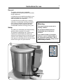
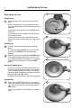
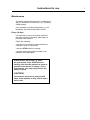
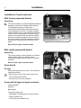
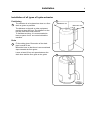
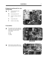
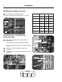
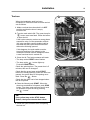
Operating and installation manual Hydro-extractor C240 / C240R C260 / C260R C290R 487 22 52 01/EN 08.28 Hydro-extractors C240/C240R, C260/C260R, C290R List of contents: Instruction for use: General, safety . . . . . . . . . . . . . . . . . . . . . . . . . . . . . . . . . . . . . . . . . . . . . Procedure for use . . . . . . . . . . . . . . . . . . . . . . . . . . . . . . . . . . . . . . . . . . . Maintenance . . . . . . . . . . . . . . . . . . . . . . . . . . . . . . . . . . . . . . . . . . . . . . . 5 6 7 Installation: Unpacking, open the lid, come with all types . . . . . . . . . . . . . . . . . . . . . . Positioning, drains. . . . . . . . . . . . . . . . . . . . . . . . . . . . . . . . . . . . . . . . . . . Quality requirements, concreting of foundation. . . . . . . . . . . . . . . . . . . . . Concreting, procedure. . . . . . . . . . . . . . . . . . . . . . . . . . . . . . . . . . . . . . . . Attachment and fitting of hydro-extractor . . . . . . . . . . . . . . . . . . . . . . . . . Technical data . . . . . . . . . . . . . . . . . . . . . . . . . . . . . . . . . . . . . . . . . . . . . . Electrical installation . . . . . . . . . . . . . . . . . . . . . . . . . . . . . . . . . . . . . . . . . Voltage change . . . . . . . . . . . . . . . . . . . . . . . . . . . . . . . . . . . . . . . . . . . . . Coin installation. . . . . . . . . . . . . . . . . . . . . . . . . . . . . . . . . . . . . . . . . . . . . Test runs . . . . . . . . . . . . . . . . . . . . . . . . . . . . . . . . . . . . . . . . . . . . . . . . . . 8 9 10 11 12 14 15 16 17 19 Safety instructions The machine must not be used by children. Do not leave children alone or unattended near the machine. The machine must not be sprayed with water. Mechanical and electrical installation and service are only to be carried out by authorised personnel. The machine's lid lock must not be by-passed under any circumstances. The machine is not to be connected to a central timer which disconnects the mains supply at a certain time. The cover cannot be opened if the current is disconnected while an extraction cycle is in progress. This means that there is a risk of the lid being opened by force. If there is a fault in the extractor e.g. when the yellow lamp at the STOP button is flashing, report the matter to the technician as soon as possible. This is important for your own saftey as well as the safety of others. The manufacturer reserves the right to make changes to design and material specifications. Instructions for use General The hydro-extractor is an invaluable complement to a washing machine and other drying equipment: It complements the washing machine by very efficient dewatering of the laundry after the wash programme is completed. It complements the tumble dryer or drying cabinet by considerably reducing the drying time. Drying of clothes is energy-intensive and an efficient hydro-extractor can save considerable amounts of energy every year. Safety The safety is controlled by two independently working rotation guards in the motor. The lid has a mechanical lock. Types C240/ C240R and C260/C260R also feature an electronic monitoring device to keep the hydroextractor from starting if the lid is not closed. If the power is disconnected, the lid will remain closed on all types of hydro-extractor. Warning The hydro-extractor must not be used by children. Do not leave children alone or unattended near of the hydroextractor. If you detect a fault on the hydroextractor, report it without delay to the technician responsible. This is important for your own safety as well as the safety of others. 1 Lid Service door 5 Instructions for use 6 Procedure for use 1 Preparation 1 Place the load in an even layer all around the drum Place long articles in a zig-zag fashion so that they are not stretched unnecessarily while being extracted. Place heavy items at the bottom and light items at the top. Check that items do not hang over the edge of the extractors drum. Finish by placing a towel or similar at the top. Be sure to keep the towel within the edge of the drum. 2 Starting up 2 Turn the cover onto the extractor and press it down. For extractor with coin box: Insert coins in the coin box; the START button will then begin flashing. 3 Start the extractor by pressing the START button. The programmed extraction time is 5 min. The lid is locked during the extraction time. If shorter extraction time is required - press the STOP button. 3 Unevenly loaded drum If the drum is unevenly loaded there will be too much imbalance during extraction The extractor will stop automatically after a few seconds and the green lamp at the button will flash. Open the lid by pressing the -button. Distribute the load evenly in the drum and restart. Completion 4 When the extraction time is over, the extractor stops automatically. Open the lid by pressing the - button. Turn the lid to the left and take out the laundry. Leave the extractor in the condition you want to find it. 4 Instructions for use Maintenance The below-mentioned intervals for maintenance apply in situations of normal use, e.g. a tenancy estate laundry. If the machine is used professionally, e.g. in a laundrette, this interval should be halved. Every 14 days It is important to carry out regular checks of the hydro extractor's function, particularly for personal safty reasons. Check the following: • that the cover cannot be opened while the extraction cycle is in progress, • that the STOP button is working, • that the switch and electrical cabel to the machine are undamaged. If the extractor has a fault e.g. when the yellow lamp at the STOP button is flashing, this must be reported as soon as possible to the person in charge. This is important for your own safety and for the safety of others. CAUTION The extractor must not be sprayed with water. If the machine is dirty, wipe it with a moist cloth. 7 Installation 8 Installation of hydro-extractor: 1 With freely suspended basket Unpacking 1 The hydro-extractor is protected against transport damage and bolted to a pallet before delivery. The transport protection consists of a wooden plug fitted between the pallet and the counterweight of the motor. Through the pallet and the wooden plug, a bolt has been entered to reach into the counterweight. When the hydroextractor is loosened from the pallet, the pallet bolts are loosened through the service door of the hydro-extractor and the transport protection bolt must be loosened from the bottom of the pallet. (A) Never lift the hydro-extractor drum! With rigidly suspended basket Unpacking The hydro-extractor comes bolted to a transport pallet and the bolts in the pallet must be loosened through the service door of the hydroextractor. Never lift the hydro-extractor drum! Open the lid All types Drain hose is placed in the drum. The lid can be opened as follows: 2 • Remove the cover of the control unit on the rear of the hydro-extractor. • Press the bar of the coil upwards. Come with all types of hydro-extractor Fitting template Spacers Base plates Clamps for drain hose * Nameplate for attachment to hydro-extractor * Hydro-extractor log * Come with some models only. 2 Installation 9 Installation of all types of hydro-extractor Positioning 1 1 Minst 250 mm The extractor is to be placed as close to a floor drain or gutter as possible. The distance to the wall or other equipment must be at least 250 mm. The distance on the left side must be at least 250 mm. To facilitate servicing, it is recommended to leave a space of min. one metre behind the machine. Drain 2 Fit the rubber hose. Dimension of the drain pipe: hose Ø75 mm. Mount the hose so that there is an unrestricted slope towards the floor gutter. Leave at least 25 mm air space between the drain hose and the floor grate or the gutter. 2 Minst 250 mm Installation 10 Installation of all types of hydro-extractor Quality requirements concerning the base The base must be very stable in order to absorb the dynamic forces transferred in the spinning process. Normally, the hydro-extractor can be attached by means of expansion bolts (size M12) directly into a concrete floor of good quality and adequate thickness - see bolt height B in the table below; or the enclosed foundation bolts can be cast into the floor, see procedure next page. Concreting of foundation for all types of hydro-extractor 1 1 If there is uncertainty as to the quality of the floor, or if the working height of the hydroextractor is too low, it could be a good idea to build up a concrete foundation. This foundation should have a height of approx. 100 mm and its minimum dimensions should be as stated in the table. Type of hydro-extractor C240/ C240R A B A C260/ C260R A 600 mm 700 mm B freely suspended basket 32 mm 32 mm B rigidly suspended basket 60 mm 45 mm Bolts for freely suspended basket 3 pcs. 4 pcs Bolts rigidly suspended basket 3 pcs 4 pcs C290R 800 mm 55 mm 4 pcs Installation 11 Installation of all types of hydro-extractor Concreting, procedure: 1 • Cut out the floor approx. 75 mm down. Make sure that the sides of the hole have an outwards slope; the lower longitudinal dimension L must be 120 mm bigger than the dimension at the edge of the floor. Build up a casting mould, see fig. 1. • Water the hole thoroughly and apply cement plaster to the bottom and sides of the hole. • Concrete the foundation. Foundation bolts can be concreted into the foundation. Use the template that comes with the machine to position the bolts. Make sure that the surface is entirely horizontal. • Allow the new concrete to dry for at least 48 hours before placing the hydro-extractor on it. Fit the hydro-extractor as described on the following pages. 1 ;;;;; ;;;;; L 100 75 L + 120 mm Installation 12 Attachment of hydro-extractor with freely suspended basket C When using expander bolts use size M12. B Bottom ring Drill holes in the floor. The depth and diameter must fit the expander bolts used. To position holes correctly you can use the template which is supplied. The extractor bottom plate can also be used as a template. Place the expander bolts in the holes. 2 mm Fitting of hydro-extractor Position the hydro-extractor and adjust it to make it completely horizontal. Place the spacers (A) below the bottom ring and around the foundation bolts. It is important that these gaskets cover the full surface of the foot. Position the square base gaskets (B) and the lock-nuts (C). It is important to fit the square gasket under the lock-nut, since this will ensure the right distribution of the mechanical load. To prevent vibration in the hydro-extractor and thus the risk of dislodgement, spacers (D) can be placed between the attachment bolts. These spacers (D) must be so high, approx. 3-4 mm, that the bottom ring will deflect approx. 1-2 mm. It is important for the bottom ring to be stressed when the bolts are fastened at full torque. NB! Check the nuts and tighten them when the hydro-extractor has been in operation for a few months. A 3-4 mm D Installation Attachment of hydro-extractor with rigidly suspended basket 13 C240/C240R Position the hydro-extractor. Adjust the extractor to make it completely horizontal. Use gaskets made of stainless or galvanised metal plate to place under the feet of the machine. The gaskets must be big enough to cover the entire surface of the foot. Fit the square gaskets and nuts. NB! Check the nuts and tighten them when the hydro-extractor has been in use for a few months. C260/C260R, C290R Installation 14 Technical data for hydro-extractors with 50 Hz and 60 Hz mains frequency Free Free suspension suspension C260 C240 Drum suspension Basket volume in litres Basket Capacity [kg] (Dry garments) 8 Basket Speed [rpm] 50 Hz 1450 60 Hz 1740 Basket G-factor [kp/kg] 50 Hz 440 60 Hz 635 Power consumption per spin [kWh] 0.04 Max. Floor load per spin (50 Hz) [kN] 1.0±0,1 Sound pressure level [dB(A)] 8 Rigid suspension C290R 12 18 50 Hz 1450 60 Hz 1740 50 Hz 1450 60 Hz 1740 50 Hz 1450 60 Hz 1740 50 Hz 1450 60 Hz 1740 50 Hz 575 60 Hz 830 50 Hz 440 60 Hz 635 50 Hz 575 60 Hz 830 50 Hz 705 60 Hz 1015 0.06 0.13 1.9±0.4 3.0±0.6 0.06 0.04 1,4±0.15 1.0±0.25 < 70 < 70 < 70 < 70 < 70 74 109 85 140 190 A Total height [mm] 850 870 910 980 1050 B Max. depth [mm] 660 785 660 785 910 C Diameter [mm] 515 640 515 640 770 D Max. width [mm] 665 790 665 790 920 E Height to drain outlet [mm] 320 330 390 420 475 Weight net [kg] A E Drain outlet Ø 75 D 12 Rigid Rigid suspension suspension C240R C260R C B Installation 15 Electrical installation. Electrical Installation is to be carried out by an authorized electrician. Switch Fit a current switch prior to the extractor. The cable between switch and hydro-extractor must comply with at least HO5VV-F in accordance with CEE(13)53 and must hang in a loop. Fuse Fit a current switch prior to the extractor. Connect the extractor to a separate fuse board. The motor is fitted with a thermal fuse, which is why separate motor protection is unnecessary. Warning The hydro-extractor must not be connected to a central timer which disconnects the power supply at a certain time. The lid cannot be opened If the current is disconnected while an extraction cycle is in progress. This means that there is a risk of the lid being opened by force. C240/C240R 50Hz Voltage Fuse, slow Cable 60 Hz Voltage Fuse, slow Cable 200 V 3 AC 230 V 3 AC 400 V 3 AC 415 V 3 AC 10A 10A 10A 10A 4 x 1.5 mm2 4 x 1.5 mm2 4 x 1.5 mm2 4 x 1.5 mm2 115 V 3 AC 200 V 3 AC 208-240 V 3 AC 380 V 3 AC 440 V 3 AC 16A 10A 10A 10A 10A 4 x 2.5 mm2 4 x 1.5 mm2 4 x 1.5 mm2 4 x 1.5 mm2 4 x 1.5 mm2 200 V 3 AC 230 V 3 AC 400 V 3 AC 415 V 3 AC 16A 16A 10A 10A 4 x 2.5 mm2 4 x 2.5 mm2 4 x 1.5 mm2 4 x 1.5 mm2 115 V 3 AC 200 V 3 AC 208-240 V 3 AC 380 V 3 AC 440 V 3 AC 25A 16A 16A 10A 10A 4 x 6.0 mm2 4 x 2.5 mm2 4 x 2.5 mm2 4 x 1.5 mm2 4 x 1.5 mm2 C260/C260R, C290R 50 Hz Voltage Fuse, slow Cable 60 Hz Voltage Fuse, slow Cable Installation 16 1 Voltage change Voltage change must be done by authorized personnel. A (Y) Some extractors have a dual voltage facility and can be changed over in connection with installation. An extractor, which upon delivery is connected for 400-415 V 3 AC (Y-connection), can be changed over to 230 V 3 AC (∆-connection) and vice versa. The change is done in the control unit. 2 How to change voltage: B (∆) For 1 machines supplied with 400 V, 415 V, 440 V 2 3 • Remove the wire harnesses A (Y) between motor and relay. A (Y) • Connect the two supplied wires harness (B) for ∆-connection, (wire harness A is for Y-connection). • Move the connector on the transformer from 400 V, 415 V or 440 V with the two pins to 230 V. By delivery 230 V vice versa. 3 Time-setting The hydro-extraction time is pre-set to five minutes. This time can be adjusted from 3-10 minutes, see fig 3 (C) and the table. NB! (D) only applies to printed circuits for coin operation. (See next page). TIME MIN. SETTING 1 2 3 3 OFF OFF OFF 4 OFF OFF ON 5 OFF ON OFF 6 OFF ON ON 7 ON OFF OFF 8 ON OFF ON 9 ON ON OFF 10 ON ON ON NB! The power must be disconnected before changing the time. 4 D OFF ON C Installation Printed circuit board for coin connection. 1 A: Screw terminal for coinpayment unit. B1: Screw-terminal for CP C1: Switch for setting number of coins. D: Jumper with joiner. 17 1 C1 D B1 E: Switch for time sitting. E A Connection 2 2 The cables from the coin reader are connected to the screw-terminal (A) on the hydro-extractor printed circuit board. a = red b = blue c = yellow a 3 3 Check that the jumpers (D) are not short-circuited (the joiner is movable). D b c Installation 18 Setting the number of coins 4 The number of coins that the hydroextractor is selected by setting switch 1+2+3 (C) No. of coins 4 OFF 1 ON C Connection to central panel (CP) CALCAD 1 • Disconnect the power to the hydro-extractor. • The right polarity is important: ± 24Vto ± 24V and 0 to 0. 2 3 1 2 3 0 OFF OFF OFF 1 ON OFF OFF 2 OFF ON OFF 3 ON ON OFF 4 OFF OFF ON 5 ON OFF ON 6 OFF ON ON 1 If the hydro-extractor is to be controlled by a central panel: Switch B1 Central panel CP GND (0) ± 24V • On the coin-PCB, pins (D) must be shortcircuited. • Switches 1-2-3 (C) must be set as in fig. 3. and schedule. 2 3 OFF 1 ON D C Switch CP 1 ON 2 OFF 3 OFF GND (0) Installation Test run 19 1 When the installation work has been completed, a functional check must be carried out as follows: 1. Make sure that the main switch is in OFF position and that the drum is empty. Close the lid. 2. Turn the main switch ON. The green lamp for - button must now flash. Press the button to open the lid. Relay 2 If the hydro-extractor receives a wrong phase sequence, relay 2 of the automatic controls (the relay normally used for braking) will be activated and the hydro-extractor will start without the lid being opened. Relay 1 If this happens, the main switch must be turned off and two of the phases in the automatic controls must be swapped, before a new functional test is carried out. 3. Close the lid. The hydro-extractor will state: • The lamp at the START button flashes. • The lamp at the - button lights up. Push the START button. Check the spinning time. The preset time is 5 minutes; this can be changed. Check that the green lamp at the START button is lit during spinning. When the time has passed, the green lamp for lid opening must flash. Press the - button. Check hat the drum has in fact stopped when the lid is opened. 4.Close the lid and push START. When the drum has reached its full speed, push STOP button. The drum must now stop and it must be possible to open the lid by pressing the - button. NB! If the yellow lamp at the STOP button flashes, the hydro-extractor has a fault. 5. Clean the hydro-extractor after completing the test run. 2 Washer extractors, Tumble dryers, Hydro extractors Types: W.55H., W3..., WN3..., W4.H., EXSM.X., H1..., N1130.., N1190.., N2..., N3..., N4..., N5... Product standards:EN 60335-2-4, -7, -11 EMF standards: EN 50366:2003 + A1 EMC standards: EN 61000-6-1 (2001) W.55H., W3..., W4.H., N1130, N1190, N2..., N3... EN 61000-6-3 (2001) W.55H., W3..., WN3..., W4.H., EXSM.X., N1130, N1190, N2..., N3... A11 (2003) WN3..., N5... EN 61000-3-11 (2001) EXSM.X. EN 61000-6-2 (2005) WN3..., N4..., N5... EN 61000-6-3 (2007) N4... Försäkran om överensstämmelse EF-samsvarserklæring Vi, Vi, Electrolux Laundry Systems Sweden AB SE-341 80 Ljungby, Sverige Electrolux Laundry Systems Sweden AB SE-341 80 Ljungby, Sverige, försäkrar under eget ansvar att denna produkt, med typbeteckning och enl. ovan, är tillverkad i överensstämmelse med följande direktiv: erklærer på eget ansvar at dette produktet, med typebetegnelse og produksjonsnummer som angitt nedenfor, er produsert i samsvar med bestemmelsene i følgende direktiver: • • • • • • • • • • • • LVD Directive 2006/95/EC EMC Directive 2004/108/EC GAS Directive 90/396/EEC (gäller endast N'''''' och WN3... CE Marking Directive 93/68/EEC RoHS Directive 2002/95/EC WEEE Directive 2002/96/EC LVD Directive 2006/95/EC EMC Directive 2004/108/EC GAS Directive 90/396/EEC (gjelder bare N'''''' og WN3... ) CE Marking Directive 93/68/EEC RoHS Directive 2002/95/EC WEEE Directive 2002/96/EC CE Declaration of conformity EG-Conformiteitsverklaring We, Wij, Electrolux Laundry Systems Sweden AB SE-341 80 Ljungby, Sweden Electrolux Laundry Systems Sweden AB SE-341 80 Ljungby, Zweden declare under our sole responsibility that the product of the type stated above is manufactured in conformity with the following EU directives: verklaren hierbij op eigen verantwoordelijkheid dat het produkt van het type en met het serienummer zoals hieronder vermeld, is vervaardigd conform de volgende normen: • • • • • • • • • • • • LVD Directive 2006/95/EC EMC Directive 2004/108/EC GAS Directive 90/396/EEC (N''''''... and WN3... only) CE Marking Directive 93/68/EEC RoHS Directive 2002/95/EC WEEE Directive 2002/96/EC LVD Directive 2006/95/EC EMC Directive 2004/108/EC GAS Directive 90/396/EEC (alleen N'''''' en WN3...) CE Marking Directive 93/68/EEC RoHS Directive 2002/95/EC WEEE Directive 2002/96/EC EG-Konformitätserklärung Dichiarazione CE di conformità Wir, die, Electrolux Laundry Systems Sweden AB SE-341 80 Ljungby, Schweden Noi erklären hiermit in alleiniger Verantwortung, daß das Produkt mit der oben genannten Typenbezeichnung mit folgenden EU-Richtlinien übereinstimmt: dichiariamo sotto la nostra esclusiva responsabilità che il prodotto del tipo specificato sopra è conforme alle seguenti direttive [UE]: • • • • • • • • • • • • LVD Directive 2006/95/EC EMC Directive 2004/108/EC GAS Directive 90/396/EEC (Nur N'''''' und WN3...) CE Marking Directive 93/68/EEC RoHS Directive 2002/95/EC WEEE Directive 2002/96/EC Electrolux Laundry Systems Sweden AB SE-341 80 Ljungby, Svezia LVD Directive 2006/95/EC EMC Directive 2004/108/EC GAS Directive 90/396/EEC (solo N'''''' e WN3...) CE Marking Directive 93/68/EEC RoHS Directive 2002/95/EC WEEE Directive 2002/96/EC Déclaration de conformité CE Declaração CE de conformidade Nous, Nós, Electrolux Laundry Systems Sweden AB SE-341 80 Ljungby, Suède Electrolux Laundry Systems Sweden AB SE-341 80 Ljungby, Suécia déclarons sous notre seule et unique responsabilité que le produit des type et numéro de série indiqués ci-dessus est fabriqué conformément aux directives UE suivantes: declaramos sob nossa inteira responsabilidade que o produto com os números de série e de tipo abaixo indicados é fabricado em conformidade com as seguintes directivas [UE]: • • • • • • • • • • • • LVD Directive 2006/95/EC EMC Directive 2004/108/EC GAS Directive 90/396/EEC (N'''''' et WN3... uniquement) CE Marking Directive 93/68/EEC RoHS Directive 2002/95/EC WEEE Directive 2002/96/EC Declaración de conformidad CE Electrolux Laundry Systems Sweden AB con sede en SE-341 80 Ljungby, Suecia LVD Directive 2006/95/EC EMC Directive 2004/108/EC GAS Directive 90/396/EEC (apenas N'''''' e WN3...) CE Marking Directive 93/68/EEC RoHS Directive 2002/95/EC WEEE Directive 2002/96/EC ΔΗΛΩΣΗ ΠΙΣΤΟΤΗΤΑΣ ΕΚ H Electrolux Laundry Systems Sweden AB SE-341 80 Ljungby, Σουηδία declara bajo su exclusiva responsabilidad que el producto cuyo tipo se especifica en el encabezado se ha fabricado conforme a las siguientes directivas: δηλώνει με αποκλειστική της ευθύνη ότι το προϊόν του ανωτέρω αναφερόμενου τύπου κατασκευάζεται σύμφωνα με τις ακόλουθες οδηγίες της Ευρωπαϊκής Ένωσης: • • • • • • • • • • • • LVD Directive 2006/95/EC EMC Directive 2004/108/EC GAS Directive 90/396/EEC (vale sólo N'''''' y WN3) CE Marking Directive 93/68/EEC RoHS Directive 2002/95/EC WEEE Directive 2002/96/EC LVD Directive 2006/95/EC EMC Directive 2004/108/EC GAS Directive 90/396/EEC (N'''''' και WN3... μόνο) CE Marking Directive 93/68/EEC RoHS Directive 2002/95/EC WEEE Directive 2002/96/EC Erklæring om EU-overensstemmelse CE megfelelöségi nyilatkozat Vi Mi, az Electrolux Laundry Systems Sweden AB SE-341 80 Ljungby, Sverige Electrolux Laundry Systems Sweden AB SE-341 8 Ljungby, Svédország erklærer på eget ansvar, at produktet med typebetegnelse som angivet er fremstillet i overens stemmelse med følgende EU-direktiver: felelöségünk teljes tudatában kijelentjük, hogy az alább megadott típusú termék gyártása a következö EU-irányelvekkel összhangban történik: • • • • • • • • • • • • LVD Directive 2006/95/EC EMC Directive 2004/108/EC GAS Directive 90/396/EEC (gælder kun N'''''' og WN3...) CE Marking Directive 93/68/EEC RoHS Directive 2002/95/EC WEEE Directive 2002/96/EC EY-Vaatimustenmukaisuusvakuutus Me LVD Directive 2006/95/EC EMC Directive 2004/108/EC GAS Directive 90/396/EEC (csak az N'''''' és WN3... esetén) CE Marking Directive 93/68/EEC RoHS Directive 2002/95/EC WEEE Directive 2002/96/EC Ljungby 2009.02.25 Electrolux Laundry Systems Sweden AB SE-341 80 Ljungby, Ruotsi vakuutamme yksinomaan omalla vastuullamme, että tuote, jonka tyyppitunnus lukee yllä, on valmistettu seuraavien [EU]-direktiivien mukaisesti: • • • • • • LVD Directive 2006/95/EC EMC Directive 2004/108/EC GAS Directive 90/396/EEC (vain N'''''' ja WN3...) CE Marking Directive 93/68/EEC RoHS Directive 2002/95/EC WEEE Directive 2002/96/EC Franco Panno Vice President Technical Operations 471 1531-43/18 Skrotning av maskin När maskinen inte längre skall användas måste den lämnas till en återvinningsstation för destruktion. Många detaljer i maskinen går att återanvända, men den innehåller även annat material som måste tas om hand på ett korrekt sätt. Lämna därför aldrig maskinen eller delar av maskinen i hushållsavfallet, eftersom det kan leda till hälsorisker eller skador på miljön. Scrapping of machine When the machine is no longer to be used, it must be submitted to a recycling facility for destruction. The majority of the components in the machine can be reused, but it also contains other material that must be taken care of in the correct way. Therefore, never mix the machine or its parts with domestic waste as this may lead to health hazards or damage to the environment. Entsorgung des Geräts Wenn das Gerät nicht länger im Gebrauch ist, muss dieses einer Recyclingstation zur Entsorgung zugeführt werden. Viele Komponenten des Geräts sind recyclingfähig, enthalten aber auch Materialien, die vorschriftsmäßig entsorgt werden müssen. Entsorgen Sie daher das Gerät oder Geräteteile niemals im Hausmüll, da dies Gefahren für die Gesundheit oder Umweltschäden nach sich ziehen kann. Mise au rebut de machine Lorsque la machine n’est plus utilisée, elle doit être déposée à une installation de recyclage pour y être détruite. La majorité des composants de la machine peuvent être réutilisés mais celle-ci contient également d’autres matériaux qui doivent être traités correctement. C’est pourquoi vous ne devez jamais mélanger la machine ou ses pièces avec les ordures ménagères, risque de polution pour l’environnement ou la santé. Desguace de la máquina Cuando la máquina no tenga que utilizarse más, ha de entregarse a una instalación de destrucción para su reciclado. La mayor parte de sus componentes pueden volver a utilizarse, pero consta también de otros materiales que han de ser tratados de la manera correcta. Por esa razón nunca mezclar la máquina ni sus partes con la basura doméstica pues esto podría constituir un peligro para la salud o dañar el medio ambiente. Bortskaffelse af maskinen Når maskinen ikke længere er i brug, skal den afleveres til destruktion på en genbrugsstation. Mange dele i maskinen kan genanvendes, men den indeholder også andre materialer, der skal håndteres korrekt. Smid derfor ikke maskinen eller dele af den ud sammen med husholdningens almindelige affald, da det kan være forbundet med sundhedsrisiko eller give miljøskader. Koneen hävittäminen Kun konetta ei enää käytetä, se pitää luovuttaa kierrätyskeskukseen tuhottavaksi. Suurinta osaa koneen osista voidaan käyttää uudelleen, mutta se sisältää myös materiaaleja, jotka pitää käsitellä asianmukaisesti. Älä sen vuoksi koskaan laita konetta tai sen osia kotitalousjätteen sekaan, sillä se saattaa aiheuttaa terveysriskejä tai vahinkoa ympäristölle. Skroting av maskin Når maskinen ikke lenger skal brukes, må den leveres til en gjenvinningsstasjon for destruksjon. Det går an å gjenbruke mange deler av maskinen, men den inneholder også annet materiale som man må ta hånd om på riktig måte. Legg derfor aldri maskinen eller deler av maskinen i husholdningsavfallet, siden det kan føre til helse- eller miljøskader. Afdanken van de machine Als de machine niet langer gebruikt gaat worden, moet deze ter vernietiging worden aangeboden bij een recyclinginrichting. De meeste componenten van de machine kunnen worden hergebruikt, maar hij bevat ook ander materiaal dat op een juiste wijze moet worden behandeld. Daarom de machine of zijn onderdelen nooit bij het huisvuil zetten, want dat kan leiden tot gezondheidsrisico’s of schade aan het milieu. Rottamazione della macchina Quando la macchina non può più essere utilizzata, deve essere affidata a un centro di riciclaggio che ne effettui la rottamazione. La maggior parte dei componenti della macchina sono riciclabili, ma ce ne sono anche alcuni che devono essere smaltiti in modo appropriato. Perciò, non mischiare mai la macchina o parti di essa con i normali rifiuti domestici, poiché ciò potrebbe comportare rischi per la salute o per l’ambiente. Złomowanie maszyny Wycofaną z użytkowania maszynę należy przekazać do zakładu utylizacji w celu złomowania. Większość podzespołów maszyny nadaje się do powtórnego wykorzystania, lecz zawiera ona także inne materiały, z którymi należy postępować w odpowiedni sposób. Z tego powodu niedozwolone jest łączenie maszyny lub jej części z odpadami domowymi, gdyż może to prowadzić do zagrożenia zdrowia lub szkody dla środowiska. Vyřazení přístroje Přístroj, který již nebude používán, by měl být odevzdán k likvidaci do ekodvora. Většina součástek přístroje může být opětovně použita, některé ale vyžadují likvidaci přesně daným způsobem. A proto nikdy nemíchejte dohromady přístoje nebo jejich části s domácím odpadem, mohlo by to vést ke zdravotním rizikům nebo k poškození životního prostředí. Οριστική απόσυρση μηχανήματος Όταν το μηχάνημα δεν προορίζεται για περαιτέρω χρήση, θα πρέπει να οδηγείται σε εγκατάσταση ανακύκλωσης για καταστροφήΤο μεγαλύτερο ποσοστό των εξαρτημάτων του μηχανήματος μπορεί να χρησιμοποιηθεί ξανά, αλλά το μηχάνημα περιλαμβάνει και άλλα υλικά η διαλογή των οποίων θα πρέπει να πραγματοποιείται με τον κατάλληλο τρόποΚατά συνέπεια, μην αναμιγνύετε ποτέ το μηχάνημα ή τα εξαρτήματά του με οικιακά απορρίμματα καθώς αυτό μπορεί να αποβεί επικίνδυνο για την υγεία ή επιβλαβές για το περιβάλλον. Art. No. 438 9041-90 / 06.21 www.electrolux.com/laundrysystems Share more of our thinking at www.electrolux.com