1
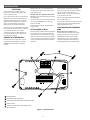
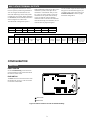
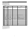
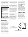
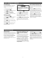
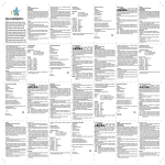
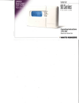
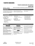
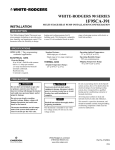
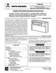
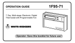
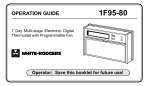
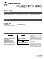
WHITE-RODGERS
COMFORT-SET® 90 SERIES
MULTI-STAGE INSTALLATION/CONFIGURATION
INSTALLATION
DESCRIPTION
This White-Rodgers Automatic Setback
Digital Thermostat uses microcomputer
technology to provide precise time and
temperature control. This thermostat offers
the flexibility to design heating and cooling
programs that fit building needs. This
thermostat is adaptable to most 24 volt
residential forced air multi-stage systems
with electric or fossil fuel auxiliary.
SPECIFICATIONS
1F95-371: 7 Day programming; residential applications
ELECTRICAL DATA
Electrical Rating:
20 to 30 VAC, 50/60 Hz with common
0.05 to 1.5 Amps per terminal
2.5 Amps maximum total load (all
terminals combined)
Standard Systems:
Multi-stage gas, oil, electric.
THERMAL DATA
Setpoint Temperature Range:
45° to 99°F (7° to 37°C)
Operating Humidity Range:
90% non-condensing max.
Shipping Temperature Range:
-4° to 149°F (-20° to 65°C)
Operating Ambient Temperature:
32° to 110°F (0° to 43°C)
PRECAUTIONS
!
WARNING
Do not short out terminals on gas valve
or primary control to test. Short or
incorrect wiring will damage thermostat
and could cause personal injury and/or
property damage.
Do not use on circuits exceeding
specified voltage. Higher voltage will
damage thermostat and could cause
shock or fire hazard.
Thermostat installation and all components of the system shall conform to
Class II circuits per the NEC code.
! CAUTION
To prevent electrical shock and/or
equipment damage, disconnect electric
power to system at main fuse or circuit
breaker box until installation is
complete.
NOTE
Read all instructions thoroughly before
beginning installation.
This thermostat is intended for use with a
low voltage system. Do not use on a line
voltage system.
Do not exceed ratings shown in the Specifications section, above. If in doubt about the
electrical ratings of your heating/cooling
system, have it inspected by a qualified
heating and air conditioning contractor or
licensed electrician.
All wiring must conform to local and
national electrical codes and ordinances.
This control is a precision instrument, and
should be handled carefully. Rough handling
or distorting components could cause the
control to malfunction.
Part No. 37-6188B
Replaces 37-6188A
0121
INSTALLATION
ATTENTION!
This product does not contain mercury.
However, this product may replace a unit
which contains mercury.
Do not open mercury cells. If a cell becomes
damaged, do not touch any spilled mercury.
Wearing nonabsorbent gloves, take up the
spilled mercury and place into a container
which can be sealed. If a cell becomes
damaged, the unit should be discarded.
Mercury must not be discarded in household
trash. When the unit this product is replacing
is to be discarded, place in a suitable
container and return to White-Rodgers at
9797 Reavis Road, St. Louis, MO, 631235398 for proper disposal.
REMOVE OLD THERMOSTAT
Shut off electricity at main fuse or circuit
breaker box until installation is complete
AND the new thermostat is configured
properly.
Remove the front cover of the old thermostat. With wires still attached, remove wall
plate from the wall.
Identify each wire attached to the thermostat using one of the labels enclosed with the
new thermostat.
Disconnect the wires from the old thermostat
one at a time. DO NOT let the wires fall
back into the wall.
Place the base over the hole in the wall
where the wires come out and mark mounting hole locations using the base as a
template. Drill 3⁄16” pilot holes, and install
screw anchors in the wall.
Run wires through hole in base and attach
base to wall (see fig. 1).
Insert the wires into the terminals on the base
using the appropriate wiring diagram and
tighten the terminal screws.
Install the new thermostat using the following procedures.
CONFIGURING AND PROGRAMMING
ATTACH BASE TO WALL
Remove packing material from the thermostat.
Place fingers of one hand on the center top
and bottom portion of the thermostat. Grasp
the base in the other hand on top and bottom
center and gently pull straight out. Forcing or
prying on the thermostat will cause damage
to the unit.
Before the power is turned on, the
thermostat must be configured to operate
properly with the system. See the CONFIGURATION section of this manual.
This thermostat can be programmed for
automatic temperature control. Refer to
Operating Instructions for programming.
4
3
2
L PH D SA SB SC OT
1
1
R
C
E
C R W3 W2 E2 W1 Y2 Y1 B
A1
P
O
G
5
1 Mounting screws
2 Pull wires through this opening
3 Insert wires into terminal holes, then tighten screws
4 Screw anchors
5 Jumper connections for remote sensor power
(Do not remove)
Figure 1. Thermostat base
2
MULTI-STAGE TERMINAL OUTPUTS
Refer to equipment manufacturers’ instructions for specific system wiring information.
You can configure the thermostat for use
with either multi-stage electric heat systems
or multi-stage gas systems. When configured
for electric heat, the G terminal (blower/fan)
will be energized on a call for heat.
This thermostat is designed to operate a
single-transformer system. If you have a twotransformer system, cut and tape off one
transformer. If transformer safety circuits
are in only one of the systems, remove the
transformer of the system with NO safety
circuits. If required, replace remaining
transformer with a 75VA Class II transformer.
After disconnecting one transformer, the two
commons must be jumpered together.
Use the terminal output information below to
help you wire the thermostat properly for
your multi-stage system. After wiring, see
CONFIGURATION section for proper
thermostat configuration.
THERMOSTAT TERMINALS (Upper)
L
PH
D
SA
SB
SC
OT
Malfunction Light
X-10 Module Input
Not Used
Remote Sense A
Remote Sense B
Remote Sense C
Outdoor Sensor
THERMOSTAT TERMINALS (Lower)
SYSTEM
Multi-Stage
E
C
R
W3/A1
W2
E2/P
W1
Y2
Y1
No Function
24 Volt
(Common)
24 Volt
(Hot)
Heat Mode 3rd
stage
Heat mode 2nd
stage
No function
Heat mode
first stage
Cool mode
2nd stage
Cool mode
1st stage
B
O
G
Blower/Fan Energized
Energized in
in on call for Cool (and
Heat and Off Energized
Cool Mode
Heat if confgured to
Mode
Electric Heat)
CONFIGURATION
SWITCHES
RESET SWITCH
See the Troubleshooting section at the end
of this document for more information about
the function of this switch.
E2/P SWITCH
1
The E2/P switch is located on the back of the
thermostat body (see fig. 2). This switch has
no function on this model.
S18
2
P S19
E2
1 Reset switch
2 E2/P switch
Figure 2. Switch locations on back of thermostat body
3
INSTALLER CONFIGURATION
BEFORE TURNING POWER ON, please
read the following instructions. Before
operating the system, you must configure
the thermostat to operate properly with
your equipment.
The thermostat, as it comes from the factory,
is configured to operate a standard multistage electric forced hot air system with a
single stage air conditioning compressor.
In this configuration, the thermostat will turn
on the fan immediately on a call for heat. If
you are unsure whether your system requires
the thermostat to control the fan, contact
your furnace/air conditioning system
manufacturer or a qualified heating/air
conditioning service person.
Your new thermostat has an Installer menu,
which allows you to customize the thermostat
to meet your requirements. (The thermostat
also has a User menu and a Keypad
Lockout menu; these menus are explained
further in the Operating Instructions.)
The menu settings can be changed at any time
to meet system or personal requirements.
ENTERING THE CONFIGURATION
MENUS.
After properly wiring the thermostat, turn on
power to the system. Momentarily press
PROGRAM RUN to make certain the
thermostat is in the run program mode, then
press TIME FWD and TIME BACK at the
same time to enter the User Configuration
menu. When the display changes to the first
item in the configuration menu, release the
buttons. Then press and hold SET TIME and
SET DAY for approximately 3 seconds to
enter the Installer menu. The display will
change to show the first item on the Installer
menu (Electric Heat Fan selection). Use the
following text, along with the Installer table
on page 5, to guide you through the menu.
Once in the menu, you set each item to the
or
, then
proper selection using
momentarily press TIME FWD to change
the display to the next item or TIME BACK
to return to the previous item.
To exit the menu at any time, press PROGRAM RUN .
ELECTRIC HEAT FAN
CONFIGURATION.
(Installer table step 1.) This menu item
determines whether fan control will be
through the thermostat or through the heating
system. If you have an electric heat or other
system that REQUIRES the thermostat to
control the fan, set this item ON. This allows
the thermostat to energize the fan immediately on a call for heat. If you are unsure if
the system requires the thermostat to control
the fan, contact the equipment manufacturer
or a qualified heating and air conditioning
service person. If your system controls fan
operation (as with most fossil fuel systems),
set this item to OFF.
SET CYCLE HEAT, COOL
(ANTICIPATION).
(Installer table steps 2 and 3). These items
allow the cycle times in heating and cooling
to be increased or decreased. The factory set
values can be adjusted higher for longer
cycles or lower for shorter cycles.
NOTE: Some manufacturers still instruct you
to set the anticipator to the current draw of
the equipment. That instruction applies only
to mercury bulb or mechanical thermostats; it
does not apply to this digital thermostat. As
configured at the factory, this thermostat will
maintain an accurate temperature. No
further adjustment is necessary, although
you can use these menu items to customize
the performance of the thermostat to your
requirements.
The adjustment range for HEATING is from
1 to 40. The factory preset is 5. The adjustment range for COOLING is from 9 to 40.
The factory preset is 13. The cooling will not
go below 9 because compressors require a
longer cycle.
The chart below shows how this adjustment
range affects thermostat performance.
PROGRAMMABLE COOL FAN-OFF
AND FAN-ON DELAY.
(Installer table steps 4 and 5.) These items
allow a selection of 0 to 127 seconds of fanoff delay after the thermostat has satisfied the
call for cool, or a fan-on delay of 1 to 30
seconds on a call for cool.
HEATING
Anticipation Value Cycle Length
The fan-off delay allows the fan to continue
running after the compressor has shut off.
This distributes the cool air that would
otherwise stay trapped in the air conditioning
coils through the ducts. Ideally the timing
would be set so the fan shuts off just as the
cool air is exhausted. If this timing is set too
long the fan may begin blowing warm air
before it shuts off. Shortening the fan-off
delay will prevent this.
A short delay to allow the A-coil to cool
off before the fan turns on may be preferred. This also allows the compressor and
the fan to come on at slightly different
times, which allows full power to the
compressor on start up. Recommended
setting for fan-on delay is 10 seconds or
less. A system that does not have a high
head pressure cutout should have a delay of
10 seconds or less.
PROGRAMMABLE HEAT FAN-OFF
DELAY.
(Installer table step 6.) This item allows a
selection of 0 to 127 seconds of fan-off delay
after the thermostat has satisfied the call for
heat if ELECT HEAT FAN (step 1) is
selected ON.
The fan-off delay allows the fan to continue
running after the burner, heating element,
etc. has shut off. This distributes the heat that
would otherwise stay trapped in the ducts.
Ideally the timing would be set so the fan
shuts off just as the warm air is exhausted. If
this timing is set too long the fan may begin
blowing cool air before it shuts off. Shortening the fan-off delay will prevent this.
COMPRESSOR LOCKOUT.
(Installer table step 7). This thermostat is
capable of protecting the system against
premature compressor failure by “locking
out” the compressor for at least five minutes
after each cycle. When the thermostat is in
compressor lockout, the word COOL will
flash on the display. With heat pump
systems, the word HEAT will flash if the
lockout occurs during a heat cycle. During
this period, the compressor will not be
energized.
(Continued on page 6)
COOLING
Differential Temperature Cycle Length Differential Temperature
1–8
Shorter
0.4–0.6°F (0.2–0.3°C)
N/A
N/A
9–20
Longer
0.6–1.0°F (0.3–0.6°C)
Shorter
0.6–1.0°F (0.3–0.6°C)
21–40
Hydronic
1.0–1.6°F (0.6–0.9°C)
Longer
1.0–1.6°F (0.6–0.9°C)
These numbers are approximate and represent operation with a typical system. Actual
temperature differentials and run times may vary widely based on your building and equipment, as well as outdoor temperature conditions.
4
INSTALLER TABLE
NOTE: You must be in the User
Configuration Menu to enter the
Installer Menu. Press TIME FWD
and TIME BACK at same time.
Step
Press Button(s)
Displayed (Factory Default)
Press
or
1
SET TIME
DAY
and SET
(hold for approx.
3 seconds)
ELECT HEAT FAN
(ON)
OFF
to select:
COMMENTS
See
Page
Fan cycles with call for heat if ON. Fan always
cycles with COOL stages.
4
2
TIME
FWD
SET CYCLE HEAT
(05)
1 to 40
Selects HEAT anticipation adjustment.
4
3
TIME
FWD
SET CYCLE COOL
(13)
9 to 40
Selects COOL anticipation adjustment.
4
4
TIME
FWD
COOL FAN DELAY OFF
(00)
0 to 127 seconds
Selects time delay for COOL fan OFF.
4
5
TIME
FWD
FAN DELAY ON
(01)
1 to 30 seconds
Selects time delay for fan ON only in COOL.
4
6
TIME
FWD
HEAT FAN DELAY OFF
(00)
0 to 127 seconds
Selects time delay for HEAT fan OFF only when
ELECT HEAT FAN (step 1) is ON.
4
7
TIME
FWD
COMP LOCK
(OFF)
ON
Selects compressor short-cycle protection enabled
or OFF.*
4
8
TIME
FWD
ECON
(OFF)
ON
Economizer option. Long Y1 cycles for cooling
with outdoor air
6
9
TIME
FWD
HEAT-OFF-COOL-AUTO
HEAT-OFF-COOL
Allows selection of HEAT and COOL or HEAT,
COOL and AUTO with SYSTEM button.
6
10
TIME
FWD
REMT SEN A
(OFF)
ON
Selects Remote Sensor A (connected to SA) if ON.
6
11
TIME
FWD
REMT SEN b
(OFF)
ON
Selects Remote Sensor B (connected to SB) if ON.
6
12
TIME
FWD
REMT SEN C
(OFF)
ON
Selects Remote Sensor C (connected to SC) if ON.
6
13
TIME
FWD
STAT SEN L
(ON)
OFF
When OFF, disables local sensor if a remote sensor
is enabled.
6
PROGRAM
Returns to normal operation
RUN
* NOTE: COMP LOCK OFF permanently
defeats compressor lockout. You must turn
this selection ON if you do not have a
system that already provides compressor
short-cycle protection. Please see “Lockout
Bypass Option” to temporarily override
compressor lockout.
5
If the system has short-cycle protection, this
item should not need to be enabled. However, if your system does not have shortcycle protection, turn COMP LOCK ON.
This will protect the compressor from shortcycling and potential premature compressor
failure.
Note that COMP LOCK OFF permanently
disables compressor lockout. If you need to
temporarily disable compressor lockout,
please see Lockout Bypass Option.
Lockout Bypass Option
FOR QUALIFIED SERVICE TECHNICIANS’ USE ONLY.
HOMEOWNERS SHOULD NOT USE
THIS FEATURE DUE TO POSSIBILITY OF EQUIPMENT OR PROPERTY DAMAGE, OR PERSONAL
INJURY.
COMPRESSOR SHORT TERM CYCLE
PROTECTION
If this thermostat has been configured to
provide short-cycle protection, during the
5-minute lockout period the thermostat
will lock out the compressor to allow
head pressure to stabilize. To override
this feature for one cycle while testing
thermostat operation, press SET TIME
and SET DAY buttons at the same time.
ECONOMIZER FEATURE.
(Installer table step 8). This item allows
longer Y1 cycles for cooling with outdoor
air.
the remote sensor for proper installation and
wiring.) After installing and connecting the
remote sensor(s) to the thermostat, use these
menu items to enable each remote indoor
temperature sensor (A, b and/or C). Note that
if SENSOR A, b or C are set to ON in the
menu, but no sensor is installed, or if the
sensor is not functioning, when you exit the
menu, CHECK STAT SYSTEM will be
displayed. To correct this, check for proper
remote sensor installation and wiring. If
necessary, return to the menu and be sure that
the remote sensor items are set correctly.
The temperature at each remote sensor can
be displayed by pressing the light button
twice within one second with the thermostat
in program run or hold mode. Temperatures
at the outdoor and indoor remote sensors will
be displayed with subsequent presses of the
light button in the following order (if
connected): outdoor sensor, sensor L, A, b, C.
(Installer table step 13). If you wish to sense
indoor temperature using ONLY the remote
sensor(s), use this menu item to disable the
temperature sensor in the thermostat
(designated as the L sensor).
When operating with remote sensor(s), the
thermostat will calculate an average of the
sensed temperatures in all enabled sensor
locations (A, b, C and/or L), then display the
average temperature as the room temperature. During programming, you can also
assign each enabled sensor different
priorities during different program periods.
This allows the system to maintain a
comfortable environment by giving higher
DISABLING AUTOMATIC
CHANGEOVER MODE.
(Installer table step 9). This thermostat, as
configured at the factory, provides automatic
changeover, which allows the thermostat to
switch between heating and cooling to
maintain temperature. In this configuration,
when you press the SYSTEM button, the
thermostat will go through HEAT-OFFCOOL-AUTO modes (HEAT-EMER-OFFCOOL-AUTO for heat pumps). Select
HEAT(-EMER)-OFF-COOL to disable the
automatic changeover feature.
OPTIONAL REMOTE TEMPERATURE SENSE.
(Installer table steps 10 through 12). Up to
three remote sensors (part # F145-1328) can
be attached to this thermostat to sense indoor
temperature at locations away from the
thermostat. Each sensor may be located as
far as 200 feet away from the thermostat.
This is an excellent feature if the thermostat
is in a poor location for sensing temperature
or if you want to install the thermostat in a
separate room to prevent tampering. (Refer
to the installation instructions included with
priority to occupied locations. At the same
time, efficient system operation is enhanced
by giving lower priority to unoccupied
locations. For detailed instructions on this
feature, see the Operating Instructions.
After using the Installer menu to properly
configure the thermostat for your system,
press PROGRAM RUN .
OUTDOOR TEMPERATURE
SENSE.
This thermostat can also display outdoor
temperature, if you install an outdoor remote
sensor with an outdoor temperature sensor
probe (F145-1378). Refer to the remote
sensor installation instructions for proper
installation and wiring. Refer to the Operating Instructions to enable this feature and
display outdoor temperature on the thermostat.
OPTIONAL ACTIVATE RUN PRG
BY TELEPHONE
With the optional X-10 Telephone Responder
(Model TR551, Radio Shack catalog RSU#
10037778) and Universal Low Voltage
Module (UM506, Radio Shack catalog RSU#
10037752) installed, you can make a
telephone call to run your program if the
thermostat has been set to Hold or Vacation
Hold. Figure 3 shows typical wiring
connections for installing the X-10 equipment. The switch on the Universal Low
Voltage module must be set to the “Momentary” position.
This option must be enabled on the User
menu (see Operating Instructions).
PH
R
4
1
2
1
2
3
4
5
Thermostat terminals
X-10 Universal Low Voltage Module
X-10 Telephone Responder Module
To 115 VAC power source
To telephone line
4
3
C
5
Figure 3. Optional X-10 connection
6
1
CHECK THERMOSTAT OPERATION
FAN OPERATION
COOLING SYSTEM
If your system does not have a G terminal
connection, skip to “Heating System”
section.
1. Turn power on to the system.
2. Press PROGRAM
RUN
.
3. Press FAN until FAN ON is displayed.
The fan should begin to operate.
4. Press FAN until FAN AUTO is
displayed. The fan should stop operating.
HEATING SYSTEM
1. Press PROGRAM
RUN
.
2. Press SYSTEM until HEAT is displayed. If
the heating system has a standing pilot,
ensure that it is lit.
to adjust thermostat setting
3. Press
above room temperature. The heating system
should begin to operate.
MULTI-STAGE OPERATION TEST
! CAUTION
To prevent compressor and/or property
damage, if the outdoor temperature is
below 50°F (10°C), DO NOT operate the
cooling system.
1. Press PROGRAM
2. Press
SYSTEM
RUN
.
until COOL is displayed.
to adjust thermostat setting
3. Press
below room temperature. The fan should
come on (after the fan-on delay time, if any),
followed by cold air circulation.
4. Press
to adjust temperature setting
above room temperature. The cooling system
should stop operating, and the fan should
stop running (after the fan-off delay time, if
any).
Follow these steps to energize all stages of
heat or cool to permit system checks during
installation.
HEAT: Press
to raise temperature
setting to 99°F, then hold for five seconds.
The second and third stage heat relays will
energize immediately for test purposes. The
LED indicator will glow green for first stage
and yellow for second and third stages.
COOL: Press
to lower temperature
setting to 45°F, then hold for five seconds.
The second stage cool relay will energize
immediately for test purposes. The LED
indicator will glow green for first stage and
yellow for second stage.
4. Press
to adjust temperature below
room temperature. The heating system
should stop operating.
TROUBLESHOOTING
RESET BUTTON
If the thermostat does not respond when keys
are pressed, or the thermostat is not operating
properly, you may use the reset button
located on the back of the thermostat body
(see fig. 2). Thermostat programming and
configuration will not be affected by
pressing the reset button. However, the clock
will need to be reset.
RESETTING THERMOSTAT CONFIGURATION AND PROGRAMMING
The thermostat can be reset back to default
programs and configuration. Removing
power from the thermostat will not reset it,
because the default settings are maintained in
permanent memory. Before resetting the
thermostat, you may want to make note of
the previously selected configuration and
programming. You must reconfigure and
reprogram the thermostat after resetting it
using this method.
7
To reset the thermostat, press and release
PROGRAM RUN , then press the FAN ,
buttons at the same
TIME BACK and
time. This will reset the thermostat to factory
default programs and configuration. The
display will momentarily go blank, then all
segments on the display will momentarily be
shown. The thermostat will then go into the
HOLD mode and will maintain factory preset
temperatures.
WHITE-RODGERS
EMERSON ELECTRIC CO.
9797 REAVIS ROAD
ST. LOUIS, MISSOURI 63123-5398
www.white-rodgers.com