1
SWAINS
CRIIFTSMIIN°
MODEL NUMBER 917.377351
OWNER'S MANUAL
. Assembly
• Operation
• Customer
Responsibilities
° Service
° Adjustments
° Repair Parts
Caution:
Read and Follow
all Safety Rules
and Instructions
Before Operating
This Equipment
159810
02.10,97
VBL
Printed in US A.,
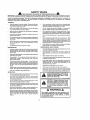
SAFETY
_Safe
IMPORTANT:
'tHtS CUTTING
FAILURE TO OBSERVE
THE
RULES
Operation Practices for Walk-Behind Mowers
MACHINE
IS CAPABLE
OF AMPUTATING
HANDS AND FEET AND THROWING
FOLLOWING
SAFETY INSTRUCTIONS
COULD RESULT tN SERIOUS
INJURY
SAFETY STANDARDS
REQUIRE
OPERATOR
PRESENCE CONTROLS TO MiNiMIZE THE
EQUIPPED
WiTH SUCH CONTROLS.
DO NOT ATTEMPT TO DEFEAT THE FUNCTION
CONTROLS UNDER ANY CIRCUMSTANCES
OBJECTS.
OR DEATH
RISK OF INJURY,
YOUR UNIT iS
OF THE OPERATOR
PRESENCE
TRAINING:
Read Ihls operator's menual carefully Become familiar w_lh
the conlrots and know how lo operate your mower prapedy
Learn haw to quickly stop mower
*
°
Do not continue to run your mower if you hit a foreign object.
FotIow the procedure outtlned above, then repair any damage before restarting and operaling you mower
Do not allow chtldrento usa your mower Never allow adulls
to usa mower without proper Instrucltons.
Do not change r the governor
settings or overspeed
angina
Engine damage or personal tnjury may resWl
Keep the area of operation clear of all parsons, especially
small childrenand pets
Do not oparale your mower if tt vibrates abnormaf{y
Exces..
siva vibration Is an indication of damage; slop the engine,
safely check for the cause of vibration and repair as required
Use mower only as the manufacturer intended and as descrlbedinthle
manual,
.
Do not operate mower If it has been dropped or damaged In
any manner, Always have damage repaired before using
your mower
°
Do not use accessory attachmentsthat are not recommended
by the manufacturer
Use of such at|achmente may be
hazardous
,
The blade turnswhen the engine ts running
.
Do not run lhe engine Indoors
cue.
•
Never cut grass by pulling the mower towards you
Mow
across the face of slopes, never up and down or you might
Ioseyourfaotlng
Donotmowexcessivetysteepstepes
Use
caution when operal_ng the mower on uneven terrain orwhen
changing directions - maintain good fooling,
•
Never operate your mower without proper guards, plates,
grass catcher or other safety devices in place
PREPARATION:
MAINTENANCE
•
•
,,
Atways thoroughlycheckthearea to be mowed and cleartt of
all stones, sticks_ wires, bones, and other foreign objects.
These objects wil! be thrown by the blade and can cause
severeinjury
•
,,
•
Check fue_tank before starling engine Do not fill gas tank
indoors,whenthe engine Is runningor when theengine ishot
Allow the engine !o cool for several minutes before ftiiing the
gas tank Clean off any spilled gasoline before startingthe
engine,
Always make wheel height adjustments before starling your
mower, Never attempt to do this while the engine Is running,
fumes are danger..
STORAGE:
Check the blade and Ihe engine mounting
sure they are tightened propedy
Check all bolls,
proper lfghlness
t[on
Always wear safety glasses or eye shields when starling and
while using your mower.
Dress properly, Do not operate mower when barefoot or
wearing open sandals Wear only solid shoes with good
trastton when mowing
AND
Exhaust
the
bolls often to be
nuts and screws al frequent inlervals for
to be sure mower Is In safe working condl..
Keep all safely devices
In place and working
•
To reduce flre hazard, keep the engine free of grass, _eavas
or excessive grease and olt
•
Check grass catcher often lot deterioration
and wear and
rap]ace worn bags
Use only replacement bags that are
recommended
by and comply with specifications
of the
manufaclurer of your mower
•,
Always keep a sharp blade on your mower
,,
Allow engine to coot before storing in any enclosure
•
Never store mower wilh fuel in the tank inside a building
where luTes may reach an open flame or an ignflion source
such as a hot water heater, apace heater, dolhes dryer, etc.
Mow only In daylight or good ad]flcial light.
OPERATION:
,'
Keep your eyesand mind on your mower and the area being
cut Do not let other Interasls distract you
"
Do notmow wet or slippery grass, Never runwh_laoperating
your mower, Always be sure of your fooling- keep a firm hold
on the handles and walk.
.
Do not puthands or test near or under rotatingpads Keep
sleet of the discharge opening at all times,
Always stop Ihe engine whenever you leave or are notusing
your mower, or before crossing driveways, walks, roads,and
any gravel-covered areas
.
Never direct discharge of material Ioward byslandars nor
allow anyonenear the mower while you are operating it.
•
Belorecleaning, inspecting,or repaldng your mower, stop the
engine and make absolutelysure the blade and all moving
pads have stopped. Then disconnect thespark plug wire and
keep It away from the spark plug to prevent accidental
starting
i
_
portan!
safety
preeautlons,
tt means
CAUTIONHI
BECOMEALERTUI
YOUR
Lookfor
this symbol
to point out ImSAFETY
!S INVOLVED
•
CAUTION:
Always
disconnect
spark
not contact spark plug in order to preplug wire and place wire where it canvent accidental
starting
when setting
up, transporting,
adjusting
or making
repairs.
The engine exhaust from this product contains chemicals Known to the State of California to cause cancer, birth defects, or other
reproductive harm.
WARNING A
I
PRODUCT
CONGRATULATIONS
on your purchase of a Sears Lawn
Mower_ t _as been designed, engineered and mamJfac-.
lured to give you the best possibie dependability
and
performance.
Should you experience any problem you cannel easity
remedy, please contact your nearest Sears Authorized
Service Center/Department.
We have competent, walltrained technicians and the proper tools to sarv{ce or repair
this lawn mower.
Piease read and retain tn;s manual
The instructions will
enable you to assemble and maintain your lawn mower
properly
Always observe the "SAFETY RULES",
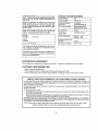
MODEL
NUMBER
SPECIFICATIONS
HORSEPOWER:
6 25
DISPLACEMENT:
'f2 56 CU IN
GASOLINE CAPACITY
AND "TYPE:
15 QUARTS
UNLEADED REGULAR
OIL TYPE (API-SF/SG):
SAE 30 (ABOVE 32"F)
SAE 5W-30 (below 32°F)
i O{L CAPACITY:
20 OZS
SPARK PLUG:
(GAP: 030")
CHAMPiON RJ19LM
VALVE CLEARANCE:
917..377351
INTAKE:
008'
EXHAUST: 008"
SERIAL
NUMBER
SOLID STATE iGNITION
AiR GAP;
,0125 IN
DATE OF PURCHASE
BLADE BOLT TORQUE:
35440 FT LBS
THE MODELAND SERIAL NUMSERSWEL
BE FOUND
ON A DECAL ATTACHED TO THE REAR OF THE
LAWN MOWER HOUSING
YOU S NOULD RECORD BOTH SERIAL NUMBER AND
DATE OF PURCHASE AND KEEP IN A SAFE PLACE
FOR FUTURE REFERENCE,
MAINTENANCE
AGREEMENT
A Sears Maintenance
CUSTOMER
Agreement
is available on this product. Contact your nearest Sears store for details°
RESPONSIBILITIES
•
Read and observe
•
Fot_'ow a regular schedule in maintaining,
the safety rules
•
Fo{low the instructions
under "Customer
caring for and using your lawn mower
Responsibilities"
ilul,i,
LIMITED
TWO YEAR
WARRANTY
and "Storage" sectlons of this owner's
illl ....................
i
ON CRAFTSMAN
ii
i
ii
manual,
illl
POWER
illll
i,
ii i i,
MOWER
For two years from date of purchase, when this Craftsman Lawn Mower is maintained, lubricated, and tuned up
according to the operating and maintenance _nstructions in the owner's manual, Sears w{_l repair free o! charge any
defect in material or workmanship
If {his,Craftsman Lawn Mower is used for commercial
the date of purchase.
or rentat purposes, INs warranty applies for only g0 days from
This Warranty does not cover:
•
Expendable items which become worn during normal use, such as rotary mower blades, brade adapters, belts,
air cleaners and spark plug,
•
Repairs necessary because of operatorabuse or negligence including bent crankshafts
the equ pment according to the {nstructions contained in the owner's manual
and the Iailure to maintain
WARRANTY SERVICE iS AVAILABLE BY RETURNING THE CRAFTSMAN POWER MOWER TO THE NEAREST
SEARS SERVICE CENTERtDEPARTMENT
IN THE UNITED STATE& THiS WARRANTY APPLIES ONLY WHILE
TH_S PRODUCT IS tN USE IN THE UNITED STATES.
This Warranty gives you specific lega_ rights, and you may also have other rights which vary from state to state
SEARS, ROEBUCK
AND CO., D/817 WA, HOFFMAN
ESTATES,
ILLINOIS
60179
u,,,,
TABLE OF CONTENTS
SAFETY RULES ................................................
,,........ ;... 2
PRODUCT SPECIFICATIONS
......................................... 3
SERVICE AND ADJUSTMENTS ..................................
15
STORAGE ............................................................................ 16
TROUBLESHOOTING
...................................... ,,.............. 17
REPAIR PARTS - LAWN MOWER ........................ 1B-23
REPAIR PARTS - ENGINE ....................................
25-27
PARTS ORDERING/SERVICE
...........................................28
CUSTOMER RESPONSIBILITIES
..................... 3, 12..14
WARRANTY ..................... _............................................
3
ASSEMBLY .......................................................................
6
OPERATION ......................................................................... 8
MAINTENANCE SCHEDULE ......................................
12
INDEX
E
A
Accessories
................. ....................... 5
Adjustments:
Carburetor .............................. 15
Drive Beit
15
Engine Speed ..............................15
Handie Height ............................ 15
Height of Cut ...........................
9
Air Filter.'
Replacement ...............................14
Service ................................
14
............
.........................
Assembly ......................................
6
B
Blade:
Sharpening ......................
Replacement .................
t3
13
C
Controls:
Drive Control .......................
Engine Zone Control ............
Engine Speed Control ............
Operator Presence
Control Bar ...........................
8
8
B
8
Customer Responstbiffties
3, 12-14
Air Filter .................................
14
Blade Care/Replacement
..... 13
Drive Wheels ........................
13
Engine ............................
14
Lubrication ............. : ...................
14
Spark Plug ................................. I4
Cutting Levels
9
Engine:
Air Filter .................................... 14
OII Change ..........................
14
Oil Level .................................... 14
Oil Type ..........................
14
Starting ..............................
!0
Slopping ..................................... 10
Storage ...................................
16
Operation:
Ddve Control ......................
Engine Contro! ................
Grass Catcher ................
Mower .............................
Operator Presence
Conlrol Bar .........................
Options:
Accessories
H
Handle Adjustment:
Assembly .......................
Cutting Height .................
3
16
10
Repair Pads:
Engine .....................
Lawn Mower .......
Responsibilities,
3, t2-14
6
15
Safety Rules .......................
15
15
15
15
Spark Plug .......................
14
.........................
..........................
Speed Control:
I_ngtne
..............................
Agreement ...........
3
Schedule ................. 12
10
O
..................................
Oth
12
16
2
Service and Adjuslmenls ......
Carburetor ................
Drive Belt .............
Engine Speed
..................
Handle
Specifications
Engine ................._..................
Storage ...................................
Customer.
25-27
18-23
S
M
Mowing Tips .............................
5
R
L
Lubrication:
Engine .................................... 14
LawnMower .............................12
Maintenance
Maintenance
g
..........................
F
Fuel:
Capacity .................
Storage ........................
Type ...............
9
9
9
9
Starting Ihe Engine
Stepping the Engine
Storage
1
5
3
8
...................
to
.................
Io
.................................
I6
T
Trouble Shooting Chart ............... 17
Warranty
W
...................
3
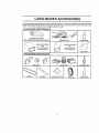
LAWN MOWER ACCESSORIES
,1,
,
, 11
.........................
11,1
11
These accessories were available when this lawn mower was produced. They are also available at most Sears retail outlets
and service centers Most Sears sEores can also order repair pads for you, when you provide the model number of your lawn
mower, Some of these accessories may not apply to your {awn mower.
LAWN
MOWER
PERFORMANCE
CLIPPING DEFLECTOR
FOR REAR DISCHARGE LAWN MOWERS
....111,111,11 111
MULCHER
FOR
REAR DISCHARGE
GRASS
LAWN CATCHERS
MOWERS
__
KITS
STABILIZER
FOR
S{DE DISCHARGE
GRASS
LAWN CATCHERS
MOWERS
GAS CANS
LAWN
MOWER
MAINTENANCE
MUFFLERS
AIR FILTERS
BLADES
BLADE ADAPTERS
SPARK PLUGS
WHEELS
ENGINE OIL
ASSEMBLY
i ii lllllllllllll
i, ,
Read these instructions and the manue! in its enttrety
before you attempt 10 assemble or operate your new lawn
mower Y0ur new lawn mower has been assembled at the
factory with the exception of those parts left unassembled
tot shipping purposes.
All parts such as nuts, washers,
bolts, etc_, necessary to comptele the assembty have been
placed in the parts bag
To ensure safe arid proper
operatfen of your fawn mower a}l parts and hardware you
assemble must be tightened securely
t. se the correct
tools as necessary to ensure proper tightness.
TO REMOVE
CARTON
•
•
•
•
LAWN
MOWER
OP_RATORPRESENCE
CONTROLBAR
UPPER HANDLE
UFTUP
FROM
MOWING POSITION
Remove loose pards included with mower
Cul down two end corners of carton and lay end panel
down flat.
Remove all packing materials except padding between
upper and lower handle and padding holding operator
presence control bar to upper handle.
Rott lawn mower out of carton and check carton thoroughly for additional loose parts
HOWTO
SET UPYOUR
LOWER
HANDLE
LAWN MOWER
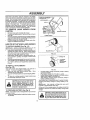
TO UNFOLD HANDLE (See Fig, 1A)
_MPORTANT:
UNFOLD HANDLE CAREFULLY SO AS
NOT TO P_NCH OR DAMAGE CONTROL CABLES.
•
Raise lower handle sectton to operating position and
squeeze the bottom ends of lower handle towards
each other unlit the pin in hand{e can be inserted Into
one et the three height adjustment holes
,
Raise upper handle section to operating position, remove protective padding and tighten handle knobs
securely.
•
Remove any packing materiel from aro und control bar
•
Your handles may be adjusted for your mowing corntort Refer to Service and Adjustments seolion of this
manual.
TO INSTALL ATTACHMENTS
(See Fig, 1 B)
Your lawn mower was shipped ready to be used as a
mulcher To convert to bagglag or discharging:
• Open rear door and remove muncher plug. Store
mutcher plug in a safe place
•
You can now Install catcher or optional ctipping deflector
•
To return to mu$chlngoperation, installmulcher plug
intodischarge opening of mower,
CAUTION: Do not run your lawn mower
without mulcher plug in place or ap*
proved clipping
deflector or grass
catcher in place. Never attempt to operate the lawn mower with the rear door
removed or propped open.
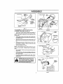
TO PREPARE BATTERY (See Fig. 2)
NOTE: Your battery must be charged before you can start
your lawn mower
•
Disconnect engine battery (male) from battery corm actor (female)
MULCHERPLUG
FIG. 1 A
PIN
3-POSITION
HANDLE
ADJUSTMENT
eRACKE_
FIG,, 1B
Connect battery charger connector (ma_e) to battery
connector (female),
•
Plug battery charger into 1!0 volt A.C. outlet.
•
Leave battery charger connected for 24 hours before
slarting your engine for the first time
Alter charging, connect engine connector (mate) to
baltery connector (female).
Your engine has an integral alternator for partial charging
Connect your battery charger te charge battery as required.
IMPORTANT:
THE ENGINE ALTERNATOR WILL NOT
CHARGE A DISCHARGED BATTERY
•
At the end of the mowing season the battery should be
charged for 48 hours to protect the battery during winter
storage
I
I _,
! A_J_,
! _
CAUTION:
Always disconnect the englne connector (male) from the battery
connector(female)topreventecctdental starting when transporting
or stop
! "J"="_
lag your lawn mower after the season_
r,, ,J,
ttt,t,,
i
,i
ASSEMBLY
ENGINE
CONNECTOR
(MALE)
BATTERY
3ER
CHARGER
CONNECTOR
(MALE)
BATtERy CONNECTOR
(FEMALE)
FIGo 2
SEWNHEM
FLIP LID
TO ASSEMBLE AND ATTACH GRASS
CATCHER (See Figs, 3A thru 4)
•
FIG. 3A
Insert leg of tubular frame through front opening of
grass catcher and thread frame into sewn hem of bag
NOTE: Keep bag hem gatllered
tubular (rame
FRAME
on the straight leg of the
•
When frame comes out the other end of sewn hem,
lmmed{atefy work the end of frame down Inside the bag
as shown in inset,
•
Slide sewn hem evenly around the tubular frame until
both ends of frame are exposed out of the front opening
CJ"
-
li I
Assemble tower frame to tubular frame as shown Be
sure handle {s outside of bag and frames are fully
seated as shown in inset,
•
FIG. 3B
Slip vinyl bindings over frame,
LOWERFRAMEHANDLE
NOTE: If vinyl bindings are too stiff, hold them in warm
water for a few minutes, If bag gets wet, let if dry before
using, '
•
Close Ih_ f!ip lid Flip lid must be closed while operating
lawn mower,
•
Lift the rear door on the mower housing and place I he
grass catcher frame onto the formed tabs on U_erear
door hinge bracket.
The grass calcher is secured to the lawn mower
housing when Ihe rear door is lowered onto the grass
catcher Irame.
CAUTION: Do not run your lawn mower
without clipping deflector or approved
grass catcher in p|aceo Never atlempt
to operatethe lawn mowerwith
the rear
door removed or propped open.
,1
,,ni,
i1
im_lJ,
11 ,o,.t,,2oo,o,)
_
_/
FIG. 3C
i
I
I
|
i
BRACKET
/
,u,Ju_
FORMED
TABS
7
FIG. 4
GRASS
CATCHER
FRAME
OPERATION
i,
iJ i,iiJ, JJ,l_Jt
KNOW
YOUR
,llUU,i,
LAWN
i
i
i
ii
MOWER
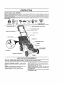
READ THIS OWNER'S MANUAL AND SAFETY RULES BEFORE OPERATING YOUR LAWN MOWER° Compare the
Illustrations with your tawn mower to familiarize yourself wtti_ the location of various controls and adjustments
Save this
manual for future reference.
These symbols
their meaning_
CAUTION
OR WARNING
may appear'on your lawn mower or in literature supplied with the product.
ENGINE
ON
ENGINE
FAST
SLOW
CHOKE
FUEL
OIL
Learn and understand
DANGER,
OFF
AND
KEEP
FEET
HANDS
AWAY
OPERATORPRESENCECONTROLBAR
" DRIVE
CONTROL
LEVER
AUXILIARY STARTER HANDLE
HANDLE_NOB
CABLE CUPS
GRASS CATCHER
GASOLINE
CAP
(ON EACH WHEEL)
MULCRER PLUG
ENGINE O}L CAP WtDIPST[OK
HOUSING
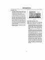
MEETS CPSC SAFETY REQUIREMENTS
Sears rotary walk.behind power lawn mowers conform to the safety standards of the American National Standards
and _he US Consumer Product Safely Commission,
The blade turns when the engine is running.
OPERATOR
PRESENCE CONTROL
- must be held
down to the handle to start the engine, Release to slop the
engine,
PRIMER - pumps additional fuet from the carburetor to the
cylinder for use when starting a cold engine,
STARTER
HANDLE - used for starting the engine.
ELECTRIC
tnstiMe
START KEY _ used for starting the engine
DRIVE CONTROL LEVER - used to engage power-propelled forward motion o[ Iawn mower.
ENGINE SPEED CONTROL - located on the side of the
engine which allows you to select either fast (_) or slow
(,,_) engine speed
MULOHER PLUG- must be removed to convert to bagging
or dlscharglng operation
OPERATION
The operation of any lawn mower can result in foreign objects thrown Into the eyes, which can
resuft in _evere eye damage Always wear safety glasses or eye shields white operating your
Iawn mower or performing any adjustments or repalrs We recommend a wlde vision safety
mask over the speclactes or standard safety glasses
HOW
TO USE YOUR
LAWN
MOWER
CAUTION: Do not run your lawn mower
without mutcherplate
in place end door
deflector
or grasscatcher
in place.
closed or without en approved clipptng
Never attempt to operate the lawn
mower with the rear door removed or
propped open°
_
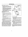
ENGINE SPEED (See Fig. 5)
The engine speed Is controlled by a lever located on the
s_de of the engine. Fast (,'_) posilion is for starttng engine,
normal culling and better grass bagging
Slow (,,,_.)
position is for iight cutting, ldmming and fuel econofny
ENGINE ZONE CONTROL
,
,, ,,,,1
u,,
H,=,H,
CAUTION: Federal regulations require
an engine control to be installed on this
lawn mower In order to minimize the
risk of blade contact injury, Do not
under any circumstances
attempt to
defeat the function of the operator control, The blade turns when the engine is
LOWER WHEELS
FOR HIGH CUT
PLATE TAB
_LEVER
................
*
_'oui lawn mower Is equipped with an operator presence cor}trol bar which requires the operator to be
positioned behind the lawn mower handle to start and
operate the lawn mower
RAISE WHEELS
FOR LOW CUT
FIG.
6
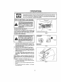
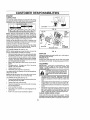
TO ADJUST CUTTING HEIGHT (See Fig. 6)
•
•
Raise wheels for low cut and tower wheels for high cr,!l.
Wheefs are sel tn Iow cut for shipping
Adjust cutting
height to suit your requirements
Medium position is
best for most lawns
•
To change cutting height, squeeze adjusfer (ever toward wheel
Move wheel up or down to suit your
requirements.
Be sure all wheels are in the same
setting.
NOTE: Ad uster is properly positioned when plate tab
inserts into hole in tever. Also, 9-position adjusters (if so
equipped) aIIow lever to be positioned between the plate
tabs
TO EMPTY GRASS CATCHER (See Fig. 7)
*
To remove grass catcher, release operator presence
contro! bar t.ostQp engine,
.
Lift up rear door and remove the gross catcher by the
handle,
•
Do not drag the bag when emptying;
unnecessary wear.
i!l will cause
FIG. 7
OPERATION
OPERATOR
DRIVE CONTROL (See Fig. 8)
•
Self-propelling is control_ed by holdlng the operator
presence contro_ bar down to the handle and pushing
the drive control lever forward until it clicks; then
re[ease the lever
•
Forward motion will stop when the operator presence
control barfs released, To stop forward motion without
stopplngengine, release the operator presence control
bar s/Ightty until the drive control disengages,
Hold
operator presence control bar down to handle to continue mowing without self-propelling,
•
•\_ _
{]F_IVE CONTROL
Your lawn mower
PJ$._J_._
FIG. 8
To keep drive control engaged when turning corners,
push down on handle and lift trent wheels ell ground
whi_eturning lawn mower,
BEFORE STARTING
OIL (See Fig. 9)
PRESENCE
CONTROL eAR
ENGINE OIL CAP
W/DIPSTICK
GASOLINE FILLER
CAP
ENGINE
is shipped without oil in the engine
•
Be sure mower is level and area around oil fill fs clean
,
Remove engine oil cap wtdlpstick and fill to the fut] line
on the dipstick_
•
Use 20 ozs. of elf. Fortypeandgradeofolltouse,
see
"ENGINE" in Customer Responsibilities seclton of this
manual.
,
Pour oil stowiy.
•
Check ott level before each use. Add oil if needed. Fit{
to full line on dipstick.
Do not over fill.
TO START
•
To read proper level, lighten engine oil cap each time.
•
To slert a cold engine, push primertive (5) ttmes before
trying to start. Use a firm push. This step is not usually
necessary when starting an engine which has a_ready
run for atew minuti_s.
•
Retnslal{ engine oil cap and lfghlen.
•
After lhe first two (2) hours of mowing, change the o11,
and every 25 hours thereafter
You may need to
change the oil more often under dusty, dirty conditions.
FIG, 9
ENGINE
*
Move engine speed control tever to fast (,_,) position
GAS (See Fig. 9)
•
Hold operator presence cent re! bar down to the ha ndle
•
•
Turn electric start key clockwise to crank engine.
IMPORTANT;
DO NOT CRANK ENGINE MORE THAN
FIVE CONTINUOUS SECONDS BETWEEN EACH T_ME
YOU TRY TO START WAiT 5 TO t 0 SECONDS BETWEEN
EACH ATTEMPT
Fill fuel tank
Use flesh, clean, regular unleaded
gasoline with a minimum ot 87 octane. Do not mix off
with gasoline. Purchase luel in quantities that can be
used within 30 days to assure fuel freshness.
WARNING:
Experience indicates that alcohol blended
fueFs (cailed gasoho_ or using ethane/or methanol) can
attract moisture which lead s to sepa ration and formation of
acids during storage
Acldio gas can damage the fuel
system of an engine while in storage
To avoid engine
problems, the fue_ syslem should be emptied before storage of 30 days or longer.. Drain the fuel tank, start the
engine and let it run until fuel lines and carburetor are
empty, Use [resh fuel next season_ See Storage instructions for additional inforrnatlon_
Never use engine or
carburetor cleaner products in fuel tank or permanent
.
To stad engtne using the auxiliary starter handle, follow
Ihe steps above. Exchange the use of the start key for
starterhandle
Puibstaderhandlequickly
Donotallow
starter rope 1o snap back.
•
To stop engine, release operator presence control bar
NOTE: _n cooler weather it may be necessary to repeat
priming steps In warmer weather over priming may cause
flooding and engine w{lf net start If you do flood engin e walt
a low minutes before attempting to start and do not repeat
pdming steps°
10
OPERATION
MOWING
TIPS
•
Under certain conditions, such as very taxigrass, it may
be necessary Io raise the helghl of cut to reduce
pushing erred and Io keep from overloading the engine
and leaving clumps of grass clippings.
•
For extremely heavy cutting, reduce the width of cut by
overlapping previously cut palh and mow stowJy
•
For better grass bagging and most culling conditions,
the engine speed should be set in the fasl ('te) position
•
When using a rear discharge lawn mower in moist
heavy grass, clumps of cut grass may not enter lhe
grass catcher Reduce ground speed (pushin g speed)
and/or _'unthe lawn mower over [he area a second time
•
If a Irai! of clippings Is left on the right side of a rear
discharge mower, mow in a clockwise direcllon with a
small ovedap to collect the clippings on the next pass.
MULCHING
•
Pores In cloth grass catchers can become filled with did
and dust with use and catchers will coilect less grass.
To prevent this, regularly hose catcher off with waler
and let dry before using
IMPORTANT:
FOR BEST PERFORMANCE,
KEEP
MOWER HOUSING FREE OF BUILT-UP GRASS AND
TRASH
SEE
"CLEAN|NG"
IN
CUSTOMER
RESPONSIBILITIES SECTION OF THIS MANUAL
•
Keep top of engine around starter clear and clean el
grass clippings and chaff This will help engine air flow
and extend engine life.
*
The special mulching blade will recur Ihe grass clippings many times ,and reduce them in size so that as
they fall onto Ihe lawn they will disperse into the grass
and not be noticed.
Also, _he mulched grass witt
btodegrade quickly to provide nutrients for the lawn.
Always mulch with your highest engine (blade) speed
as this wl!l provide the best recuttlng action of the
blades
,
Avoid cutting your lawn when It ts wet Wet grass tends
to form clumps and interferes with the mulching action
The best time to mow your lawn is the early afternoon.
At this time the gi'ass has dried and the newly cut area
will not be exposed to the direct sun
,
For best results, adjust the lawn mower cutting height
so that the lawn mower cuts off only the top oneqhfrd
of the grass blades (See Fig, 10). If the lawn is
overgrown it will be necessary to raise the height of cut
to reduce pushing effort and to keep from overloading
the engine and leaving clumps of mulched grass.. For
extremely heavy mulching, reduce your width of cut by
overlapping previously cut path and mow slowly
•
Certain types of grass and grass sondilions may require that an area be mulched a second time to
completely hide the clippings
When doing a second
cut, mow across or perpendicular to the first cut path
•
Change your cutting pattern from week to week. Mow
north to south one week then change to east to west the
next week. This will help prevent matting and graining
of the lawn
FIG. 10
11
MOWING TIPS
CUSTOMER
,i
i
RESPONSIBILITIES
i
,n,,,,,
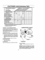
AsYoUCOMPLETE
REGU ARsE v!oE
,.Checkfor LooseFa._;leners
Cteanflnspect Grass Calche_
(If Equipped)
M Clean Lawn Mower
0 Clean Under Ddve Covet
,tU (Powor-Prope,,ed Mowers)
Check drive bali/pulleys
{P£wer:Pro_e!led Mowers)
R : ChecldSharpen! Bep!ace #!ad#
Ch_no_
mole
O|IO_l w!_orl ope_s||_
,
,
SERWCE
DATES
. I_
Lubrication Chart
Clean BaIletyfRecharge
IElectdo Start Mowers)
E Check Engine O[i Lave1
N cb_ng_Engine O]I
G Clean Air Filter
I lnepeel Mu!ller
N clean et Repiace Spaik'Plug
I"
,
undD_ _ 11_i_
I_
_
If
___ ..___.
f_
.
.
f/,
IVY
_
iv/
V'
_
_,/4
I,/
V'
V_
if
_ ............
................
....
" '
_
laird
or in h_gh $1mb_l_|
I
lampol_rt_m_
2 SefVl_O mota atlon whoa opg_ef_r_gJfldirt F er d_sly cond)_ion_
3 , R_placo btade_ more el|on when mewln_ tn _andy" s_ll,
4
Ch[=lgo
GENERAL
48 houm
Ol _I_ O_ _O_O0
LUBRICATION
RECOMMENDATIONS
CHART
WHEEL
ADJUSTER
The warranty on this lawn mowerdoes not cover items that
have beer_ subjecled to operator abuse or negligence To
receive full value from the warranty, operator mustmalntatn
mower as Instructed in this manual
Some adjustments will need to be made periodically
properly malntaln your unit
to
All adjustmenls in the Service and Adjustments section of
this manual should be checked at least once each season,
•
Once a year, replace the spark plug, replace air filter
element and check blade for wear° A new spark plug
and cleantnew air filter element assures proper air-fuel
mixture and helps your engine run better and last
longer
•
Fellow the maintenance
DRAKE
SPRING
BRACKET
(_)ENG1NEOIL
schedule in this manual
BEFORE EACH USE
•
Check engine otl level
•
Check for loose fasteners,
REAR
HINGE
(_)HANDLEBRACKET
MOUNTING PiN
LUBRICATION
Keep unit well lubricated
DOOR
(See "LUBRICATION
CHART")
(_)
SPRAY
LUBRICANT
(_
REFER
TO
CUSTOMER
RESPONSID1UTIES
"ENGINE"
SEC-
TION,
IMPORTANT: DO NOT OIL OR GREASE PLASTIC WHEEL
BEARINGS
VISCOUS LUBRICANTS WILL ATTRACT
DUST AND DIRT THAT WILL SHORTEN THE LIFE OF
THE SELF LUBRICATING BEARINGS, IF YOU FEEL THEY
MUST 8E LUBRICATED, USE ONLY A DRY, POWDERED
GRAPHITE TYPE LUBRICANT SPARINGLY
!2
CUSTOMER
LAWN
RESPONSIBILITIES
MOWER
BLADE
ADAPTER ,..
Always observe safety rules when performing any maintenance
TIRES
. CRANK../ SHAFT
t,-'--"_._
KEY _/"_"_
•
Keep tires free of gasoline, oil, or insect control chemicals which can harm rubber
•
Avotd stumps, stones, deep ruls, sharp objects and
other hazards that may cause tire damage
_
KEYWAY
BLADE CARE
For best resutts, mower blade must be kept sharp,,
place beht or damaged blades,
Re-
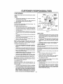
TO REMOVE BLADE (See Fig 11)
•
•
]
Disconnect spark plug wire from spark plug end place
wire where it cannot come in contact wilh spark plug.
Turn lawn mower on its s_de. Make sure air filter and
carburetor are up
•
Use a wood block between blade and mower housing
to prevent blade from turning when removing blade
bolt.
•
Protect your hands with gloves andlor wrap blade with
heavy cloth
"
Remove blade bolt by turning counter-clockwise
a 9/t6" box or open-end wrench
•
Remove blade and attaching
washer and hardened washer)
HARDENED
I
WASHER
LOCK WASHER
\
\
TRAILING "_
EDGE
BLADE ADAPTER
FIG. 1t
GEAR CASE
•
To keep your drive system working properly, the gear
case andarea around the drive should be kept clean
and free of trash build-up., Clean under the drive cover
twice a season,
(bolt, lock
•
NOTE:
Remove tt_e blade adapter and check the key
inside hub of blade adapter. The key must be in good
condition to work propefly_ Replace adapter if damaged
The gear case is fi!led with lubricant to Ihe proper Ievel
at the factory
The only time the lubricant needs
attention Is If service has been performed on the gear
case
•
TO REPLACE
If lubricant is required, use only Texaco Sfarplex Premium Grease, part no., 750355, Do not substitute
DRIVE WHEELS
•
hardware
Use
BLADE (See Fig 11)
Position the blade adapter on the engine crankshaft,
Be sure key in adapter and crankshaft
keyway are
aligned,,
Check front drive wheels each fime before you mow to be
sure they move freely
•
Position blade on the blade adapter aligning the two (2)
holes in the btade with the raised tugs on the adapler.,
•
Be sure the trailing edge of bfade (opposite sharp
edge) is up leward the engine_
The wheels not turning freely means trash, grass cuttings,
etc are in the drive wheel area and must be cleaned to free
drive wheels
•
tnstalIthe blade bolt withthe lock washer and hardened
washer into btade adapter and crankshaft
•
Use block of wood between blade and lawn mower
housing and tighten Ihe blade bolt, turning clockwise.
If necessary
wheels.
•
The recommended tightening torque is 35-40 ft. [bsIMPORTANT: BLADE BOLT tS GRADE 8 H EAT TREATED,,
to clean the ddve wheats, check both front
•
Remove hubcaps, hairpin coilers and washers
•
Remove wheels from wheel adjusters
•
Remove any trash or grass cuttings from inside the
dust cover, pinion and/or drive wheel gear teeth
•
Put wheels back in place
NOTE_ We do not recommend sharpen[ng blade - but ifyou
do, be sure the blade is batancedo
•
[f after cleaning, the drive wheels do r_ot turn freely,
contact your nearest servtce center.
TO ,SHARPEN BLADE
GRASS CATCHER
Care should be taken to keep the blade balanced
An
unbalanced blade will cause eventual damage to lawn
mower or engin e .
•
The grass catcher may be hosed with water, but must
be dry when used.
•
Check your grass catcher often lor damage or detefio*
ration, Through normal use it wilt wear. If catcher
needs replacing, replace only with a manufacturer
approved replacement catcher Give the lawn mower
model number when ordering,
•
The blade can be sharpened with a file or on a gflndlng
wheel Do not attempt to sharpen white on the mower
•
To check blade batance, drive a naiilntoa beamorwstL
Leave about one inch of the straight na[f exposed.
Place center hole of blade over the head of the nail If
blade is balanced, II should remain in a horizontal
position. If either end of the blade moves downward,
sharpen the heavy end untlt the blade is balanced.
13
CUSTOMER
iii
nuul
mlllnnl
RESPONSIBILITIES
ENGINE
LUBRICATION
Use only high quality detergent oif rated wfth API service
ctessification SF crag
Selecl the oil's SAE viscosity grade
according to your expected operating temperature.
SAE VISCOSITY
GRADES
CONTAIN_ER
FIG. 12
_r,E_'run_
COLLAR
_N_E ._T_C_PATED
8E_OR_
_q'O_L C_N_E
TURN
COUNTER,
CLOCK_
WTSE
NOTE: Aithough multi-viscosity oils (5W30, 10W30 etc )
improve starting in cold weather, these multl-viscosity oils
will resutt in increased off consumption when used above
32°F, Check your engine oit level more frequently to avoid
possible engine damage from running low on o1I.
Change the oil after the first two hours of operation and
every 25 hours thereafter or at least once a year If the iawn
mower is nol used for 25 hours In one year.
SLOT
Check the crankcase olt level before starting the engine
and after each five (5) hours of continuous use Tighten oil
plug securely each time you check the oit level.
TO CHANGE
AIR FILTER
AIR FILTER COVER
ENGINE OIL (See Fig. 12)
FIG,,13
NOTE: Before tipping lawn mower to drain oit, drain fuel
tank by running engine until fuel tank ts empty
,
Disconnect spark plug wire from spark pfug and place
wire where it cannot come in contact with spark plug
•
,
Remove engine olI cap; lay aside on a clean surface.
Tip fawn mower ORIIs side and drain oil tote a suitable
container. Rock lawn mower back and forth to remove
any oil trapped inside of engine
•
•
•
"
MUFFLER
Inspect and replace corroded mu!fler as it could create a
fire hazard and/or damage,
SPARK PLUG
Change your spark plug each year to make your engine
start easterand runbetter Set spark plug gap at .030 inch
Wipe off any spilled oil on lawn mower and on side of
engine.
Fti[ engfne with oil
FIll only to the "FULL." fine on the
dipstick. DO NOT OVER FILL.
CLEANING
A
,_JL
Your engine witl not run properly and may be damaged by
using a dtdy air filter
•
•
•
Turn lawn mower on its side. Make sure air filter and
carburetor are up, Clean the underside of your lawn
mower by scraping to remove build-up of grass and
trash.
t
Clean engine often to keep trash from accum u{atlng. A
clogged engine runs hotter and ahodens engine life.
to the
Clean the inside of the cover and the coIlar to remove
any dirt accumulation
Insert new filter Into cover
•
Put air filter cover and filter Into collar aligning the tab
with the sIot
•
Push In on cover and turn clockwise
........
*
AIR FILTER (See Fig, !3)
Remove the air _ter by turning counterclockwise
stop and pull away from collar,
Remove filter from Inside of cover,
CAUTION: Disconnect spark plug wire
from spark plug and place wire where tt
cannot come In contact with the spark
p,,g
Replace the air filler every year, more often It you mow In
very dusty, dirty condlltons.
Do not wash air litter,
•
'
IMPORTANT:
FOR EtEST PERFORMANCE.
KEEP
MOWER HOUSING FREE OF BUILT-UP GRASS AND
TRASH
CLEAN UNDERSIDE OF MOWER HOUSING
AFTER EACH USE.
Replace engine oilcap.
Reconnect spark pfug wire to spark plug
TO CHANGE
TURN
CLOCKWISE
TO TIGHTEN
Keep finished surfaces and wheels free of all gasollne,
oil, etc.
We DO NOT recommend usin_ a garden hose to ctean
lawn mower unless the electncal system, muffler, air
filter and carburetor are covered lo keep water out.
Water in engine can result in shortened engine life
to lighten,
CLEAN UNDER DRIVE COVER
Clean under drive cover at least twice a season. Scrape
underside of cover with putty knife or similar Ioo_to remove
any build-up of Irash or grass on underside of drive cover
14
SERVICE AND ADJUSTMENTS
t
,_
,_
CAUTION:
BEFORE PERFORMING
Release control barn
*
•
ANY SERVICE
OR ADJUSTMENTS:
f
i
Make sure the blade and all moving parts have completely stopped,,
Disconnect spark plug wire from spark plug and place where it cannot come in contact
LAWN MOWER
TO ADJUST CUTTING HEIGHT
,See "TO ADJUST CUTTING
section of this manual,
REAR
HEIGHT"
in the Operation
DEFLECTOR
The rear deflector, attached between the rear wheels of
your lawn mower, is provided to minimize the possibility
that objects will be thrown out the rear of the lawn mower
into the operator's mowing position
If the rear deflector
becomes damaged, it should be replaced
DRIVE
COVER
BELT
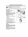
TO REMOVE/REPI-,r_cE DRIVE BELT
(See Fig; 14)
•
Remove drive cover
gear case pulley,
,,
Turn lawn mower on its side with carburetor
cap up
•
Remove blade,
PUSHDOWN
Remove _e_tby pushing down on
FIG. 14
and fuel
Remove debris shield
Remove belt from engine pulley on crankshafl,
•
insta!l new belt by reversing
•
Always use factory approved belt to assure fft and tong
life
above steps,
TO ADJUST HANDLE (See Fig. 15)
The handle on your lawn mower has three (3) height
positions - adjust to heighl that suits you,
"
Squeeze the bottom ends of lower handle towards
each other untl! the p_n In handie can be inserted Into
one of lhe three height adjustment holes,
FIG- 15
ENGINE
ENGINE SPEED
Your engine speed has been factory set. Do not attempt
to increase engine speed Dr it may result in personal injury,
If you believe that the engine ts running too fast or too slow,
take your lawn mower to an authorized
service center/
department for repair and adjustment
CARBURETOR
Your carburetor has a non-adlustable fixed main jet for
mixture control If your engine does not operate properly
due to suspected carburetor problems, take your lawn
mower to an authorized
service centeddepartment
for
repair and adjustment.
15
i
with plugo|
I
STORAGE
Immediately prepare your lawn mower for storage at the
end of the season or if the unit will not be used for 30 days
or more
ENGINE
LAWN
IMPORTANT:
IT IS IMPORTANT TO PREVENT GUM
DEPOSITS
FROM FORMING
iN ESSENTIAL
FUEL
SYSTEM PARTS SUCH AS CARBURETOR, FUEL FILTER,
FUEL HOSE, OR TANK DURING STORAGE.
ALSO,
EXPERIENCE INDICATES THAT ALCOHOL BLENDED
FUELS (CALLED GASOHOL OR USING ETHANOL OR
METHANOL) CAN ATTRACT MOISTURE WHICH LEADS
TO SEPARATION AND FORMATION OF ACIDS DURING
STORAGE.
ACIDIC GAS CAN DAMAGE THE FUEL
SYSTEM OF AN ENGINE WHILE IN STORAGE
FUEL
MOWER
When lawn mower Is to be stored for a period of time, clean
tt thoroughly, remove all dirl, grease, leaves, elc_ Store in
a clean, dry area.,
.
Clean entire lawn mower
Customer Respons_bililies
(See "CLEANING" in the
section of this manual},
•
Lubricate as shown In the Customer
section of this manual
•
Be sure that all nuts, botts, screws, and prns are
securelyfastened,
inspect movJngpartsfordamage,
breakage and wear Replace if necessary,
.
Touch up all rusted or chipped paint surfaces;
lightly before painting
Responsibilities
sand
*
Drain the fuel tank
.
Starl the engine and Iet it run untl! the fuel lines and
carburetor are empty
•
Never use engine or carburetor cleaner products in the
fuel tank or permanent damage may occur,
Use fresh fuel next season
•
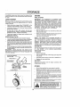
HANDLE
(See Fig.16)
°
You can fold your fawn mower handle for storage,
•
Loosen the two (2) handle knobs on sides of the upper
handte and allow handle to fold down to the rear.
•
Squeeze the bottom ends of lower handle toward each
other unt]! pins in handle clear the brackets and pivot
entire handle assembly forward and a[fow it to rest on
mower
•
When setting up your handle from the storage position
the ower handle wilt require manually lock}rig into the
mowing position,
IMPORTANT:
WHEN FOLDING THE HANDLE FOR
STORAGE OR TRANSPORTATION,
BE SURE TO FOLD
THE HANDLE AS SHOWN OR YOU MAY DAMAGE THE
CONTROL CABLES
SYSTEM
NOTE.
Fuel stabilizer is an acceptable alternative in
minimizing the formation of fuel gum deposits during storage, Add stabilizer to ease}the In fuel lank or storage
container. Always foltow the mi× ratio found on stabilizer
container.
Run engine at least 10 minutes after adding
stabilizer to allow lhe stabf_izer to reach the carburetor. Do
not drain the gas tank and carburetor if using fue_ slabilizer,,
ENGINE OIL
Drain oil (with engine warm) and replace with clean engine
oil
(See "ENGINE"
in the Customer Responsibilities
section of this manual)
CYLINDER
OPERATOR PRESENCE
CONTROLBAR
UPPERltANDLE
•
Remove spark plug
.
Pour one ounce (2g ml) of eli through spark plug hole
into cylinder
.
Pui_ starter handle slowly a few times to distribute
•
Replace with new spark pJug,
oi!
BATTERY
FOLD FORWARD
FOR STORAGE
Dlsconnect the battery from the engine connector
charge battery 48 hours,
FOLD BACKWARD
and
OTHER
MOWING
POSITION
LOWER HANDLE
•
Do not store gasoline from one season to another
•
Replace your gasoline can if your can starts to rust,
Rust and/or dirt in your gasoline will cause problems,
.
if possible, stere your unit indoors and cover it to give
protection from dust and dirt
•
Cover your unit with a suitable protective cover that
does not retain moisture. Do not use plastic. Plastic
cannot breathe which allows condensation to form and
wi}l cause your unit to rust.
IMPORTANT: NEVER COVER MOWER WHILE ENGINE
AND EXHAUST AREAS ARE STILL WARM
I&
FIG. 16
16
with gasoline in the tank inside a buildIng where fumes may reach an open
flame
or spark_
Allow
the engine to
cool
CAUTION:
Never
etorethelawn
mower
before storing in any enclosure°
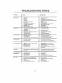
TROUBLESHOOTING
PROBLEM
CAUSE
Done not atart
t
2
3
4
S
B
7
8
9
10
tI
Loss of power
Poor
cut - uneven
Excessive
vibration
Starter rope herd to pufl
1
POINTS
CORRECTION
Oldy air filter
Out of fuel
Stale |eel
Water tn fuel
1
2
3
4
Spa_ plugwlrels d_scoonected
Bad spalk plug
Loose blade or broken blade edapler
Control bar tn released position '
Control bar defective
Week battery
Dtscoonacfed bottely connector
5
6
7
8
9,
10
It,
Clean/replace air triter
FIll fuel tank
Drain tank and refillwlgt flesh clean feet
Drain fuel tank and carburetorand ref_l _enkwith fresh
gasotfns
Connect wire fo plug
Replace spark plug
Tighten blade bait er replace blade adapter
Depress centrolbar to handle
Replace control bar
Charge bailer,!
Connect betlery lo engine
1
Set tn "Higher
2
3
4
5
6
Rear of lawn mower housing/blade draggtng
in heavy gross
Cutting Ieo much grass
Drily air tilter
Buildup el grass, leaves end trash under mower
Tea much ell in engine
Welking speed leo fast
2
3
4
5
6
Sol tn "Higher CuF position
CleenHeplece air filler
Clean ,Jnde_lde of mower housing
Check oil level
Cat a! stowar walking speed
1
2
3
4
Were, bent or loose blade
Wheel hatghts uneven
Low englnespeed
Buffdup el grass, leaves, and {rach under mower
1
2
3
4
Rsptace blade Ttghlen blade bolt,
So! aft wheels at same height
Set engine speed control In fast position
Cleon underside el mower housing
1
2,
'Atom. bent or loose bfeda
Bent engine cran_hag
t
2
Repieca btade, Tighten btade bait
Contact euihadzed service cenier/depallment
1
Engine tlywheet br'&_e Is on when cenlral bar Is
released
Bent engine crankshaft
elade edepte_"broken
Blade dragging In grass,
"_
DepreSs
2
pulling starter tope
C._nlacl aulhodzed
3
Replace
4
Move
2
3
4
In stad
Loss of drive
Grass catcher not filgng
(ff so equfpped)
,i
,
!
2
Ddva wheels nottumlng with ddse con|rot en0agsd
Belt ool dflvlng
1
2
CuffingheIghl too tow
Lift onbtods worn oft
3
4
Catcher not venting air
Lowengtne speed
t
2
Grass ts too high or wheel height Is Icetoy,,
Rear of lawnmower houslngfblade dragging
In grass
Grass catcher too full
Handle height position
notdght for you
Cut" position,
control
blade
bet to Upper handfe
service
before
centerldapartment
adapter
lawn mower
to out grass or to hard surface
angina
1
Adlast
2
Put bolton pulleys
or replacebeltsIfbro_,en
Or repteca ddve
control
cable,
tf broken
1
2
3
4
Raise cutting helghl
Replace blade
Clean grass c_lcher
Set englna speed controfIn fast position
1
2
Raise cutting height
Raise rear of fawn mower housing dna (t}
sailing higher
Empty grass catcher
Ad}ust handle height to ouff
,
Hard to push
3
4
17
3
4
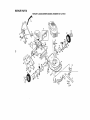
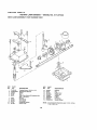
REPAIR
PARTS
ROTARY
LAWN
MOWER
MODEL
NUMBER
917.377351
9
24
27
L4
12
37
65
3O
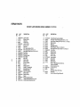
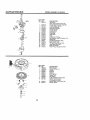
REPAIR PARTS
ROTARY
KEY
NO.
PART
NO
1
2
5
6
7
9
10
11
12
13
14
15
16
17
20
2t
22
23
24
25
27
28
29
30
31
32
34
36
37
39
145640X479
151501
151517
87892
STD541425
151023
128415
150050
STD5t2505
144929
700494X479
?00365)(479
133190,"{479
140661)(479
140540
150425
85543
87677
150181
83923
150341
142748
62335
145935)(004
701037
700331X004
146630
700325)(007
150878
153131X479
LAWN
MOWER
MODEL
NUMBER
DESCR|PT|ON
KEY
NO.
PART
NO
Upper Handle
Engine Centm_
Cable Clip
Handle Knob
Loctm_,_t1/4-20
Rear Do_r Kit
Pop Rivet
Self Tapping Screw #10-24
He× Tapping Screw 1/4-20 x 1/2
Hex Washer Head Sc._ew 1t4-20 x 2t12
Back Plate
Side Baffle
Discharge Baffle
RearBa_e
RearSkirt
Mulcher Plug
Engine Pulley
HFPro Key #508
Hubcap
Flanged Locknut
Wheel & Tire Assambty
Shoulder Bolt 3/8-16
Belleville Washer
Axle Arm Assembly
Selector Knob
Selector Spnng
Spacer
Wheel Adiusting Bracket
Thread Cutting Screw 5/'16-18 x 3/4
Handle Bracket Assembly (Lefl)
40
41
44
46
47
48
49
50
51
52
55
56
57
58
59
61
62
64
153130)(479
150406
153281
851514
157101
851074
850263
851084
700869X479
85463
751592
88652
51793
15!723X479
131959
132001
134612
......
85
66
87
150502
STD541431
66426
72
......
73
--
850724
159810
917.377351
DESCRIPTION
Handle Bracket Assembly (Right)
He× Head Thread Roiling Screw 3/8-16 x 1-1t8
Lawn Mower Housing (incl. Key #14,15, t7, 5t &52)
Blade Adapter
Blade 22"
Hardened Washer
HelicaJ Washer 3/8-24 x 1-3/8 Grd. 8
Hex Head Machine Screw 3;8-24 x t-_8 Grd. 8
Front Baffle
Danger Decal
Locknut 3/8-16
Hinge Screw
Hairpin Cotter
Lower Handle
Handle Bolt
Rope Guide
Debris Shield
Engfne - {See Breakdown)Craftsman
Model 143.976252
Handle Adiustment Pin
Locknut 5fl6-18
Wire Tie
See Battery Repair Parts Page
Foam Grip
Owneds Manual (English/Spanish)
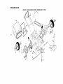
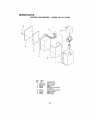
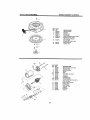
REPAIR
PARTS
ROTARY
LAWN
MOWER
MODEL
NUMBER
917.377351
54
18
10
14
15
1
8
12
_37
16
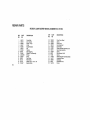
REPAIR PARTS
ROTARY
KEY
N_
!
2
4
5
6
7
8
10
11
12
t3
t4
15
16
18
PART
NO.
145974
148312
144929
145527
150495
145212
I50182
88446
150340
12000058
137054
88080
88118
67725
701037
LAWN
MOWER
MODEL
NUMBER
DESCRIPTION
KEY
NO,
Control Bar
Dnve Control
Screw 1/4-20
V-Belt
Spring Retainer
Nut
Hubcap
Nylon Bushing
Wheel & Tire Assembly
E-R{ng
:P_nion
Dust Cover
FettWasher
Washer 112 x 1-1/2 x,134
Selector Knob
25
27
28
31
32
35
36
37
38
40
41
53
54
55
58
PART
NO
t52903
143603
154990
132010
137052
151521
702511
137090
63601
75192
15'I520
144747
149844
86012
144748
917.377351
DESCRIPTION
Drive Cover Decal
Screw
Dnve Cover
Hex Flange Nut
Drive Pul|ey
Wheel Adluster Assembly (Left)
Gear Case Assembly
Spdng
Hex Locknut 1/4-20
Spnng
Wheei Adjuster Assembty (Right)
Grassbag Frame
Grassbag
Dnveshaff Cover
Frame
nl-r/._in
r/-in
i o
ROTARY
LAWN
MOWER
--
MODEL
NO. 917,377350
GEAR CASE ASSEMBLY PART NUMBER 702:511
7
KEY
NO,
PART
NO,
1
2
3
4
5
17490418
137055X004
137053
57072
48373
7
8
9
10
11
7788t
137051
137074
57079
131484
DESCRIPTION
Tapping S_rew I/4-20x 1-114
Engagement Bracket
Shifter
Sea{
Gear Case Halves Kit (includes Key
Nos. 4, 5, and 7)
Beadng
WormShaft
Drive Shaft
Hardened Washer
Cfutch Yoke
KEY
NO,
PART
NO.
DESCRIP'I'|ON
12
13
14
15
16
17
18
19
700343
86447
137050
750436X
750369
12000003
850848
81585X004
Bushing
Pfug
Heltca_ Gear
Clulch Jaw
Grease
E-Ring
HI-Pro Key
Spring Bracket
NOTE:
22
AJI component dimensions given in U3.
1 Inch = 25 4 mm
inches,
REPAIR PARTS
ROTARY
LAWN
MOWER
-- MODEL
NO. 917.377350
4
KEY
NO.
PART
NO.
1
2
3
4
86334X479
86337X479
750909
750097
5
6
7
8
86353
111549X
86649
134861
DESCRIPTION
Battery Bracket
Batlery Cover
Batter!
Hex Washer Head Screw
# 10-24 xl/2
ConnectorMounttng
Clip
8altery Charger
8atte_y Pad
Battery Wrap
23
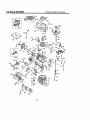
4-CYCLE
ENGINE
II III I1'1'
I'1
I
MODEL
I
I
I
II'l'lll
9O0
4OO
416
119
I25
277,
I
f
223,
NUMBER
.."
_74172
207
370C
24
'111
I
143.976252
i
I
4-CYCLE ENGINE
KEY
NO,
1
2
6
7
12A
12B
14
15
t6
17
18
19
20
30
40
40
40
41
41
PART
NO.
36478A
26727
33734
36557
36558
34695
28277
30589
32651
31335
651018
36261
32600
35801
36073
36074
36075
36070
36071
41
36072
42
42
42
43
45
48
48
50
52
69
70
72
73
75
80
5I
82
83
86
89
90
92
93
!00
101
103
110
110A
110B
119
120
125
t25
36076
36077
36076
20381
32875A
32610A
27241
35992
29914
35261
34311D
30572
28833
27897
30574A
30590A
3O591
30588A
650488
611004
811150 ,
650815
650816
34443A
610118
651007
34951
36953
36954
36477
36476
36471
36472
126
t26
130
135
150
151
169
172
174
178
182
184
185
293146
29315C
602tA
35395
35991
31673
27234A
32755
30200
29752
620t
25756
36544
MODEL NUMBER 143,976252
KEY PART
NO. NO.
186 34337
189 650831
191 36559
195 610973
200 35727
202 36482
203 31342
204 650549
205 650777
207 34336
209 30200
2t5 3551t
223 550451
224 34690A
238 650932
239 34338
241 36919
245 36905
250 36920
260 36915
261 30200
262 650831
263A
36921
275 36473
277 650988
285 35000A
287 650926
290 29774
292 26460
298 28763
300 36916
301 36246
305 35647
308 36832
307 35499
309 550562
310 35648
313 34080
314 850767
315 36952
322 35013
322A
610885
325 35249
347 651038
370A
36261
370B
35167
370C
36861
380 632747
390 590702
395 35709
400 36,181
416 36085
DESCRIPTION
Cylinder (Incl. 2,7,20 & 125)
Dowel Ptn
Breather Element
Breather Ass'y. (tncL 6 & 12A)
Breather Cover & Tube (Inel. 126)
Breather Tube Elbow
Washer
Governor Rod (IncL 14)
Governor Lever
Governor Lever Clamp
Screw, Torx T-!5, 8-32 x 19/64"
Extension Spring
Oil Seat
Crankshaft
Piston, pin & Ring Set (Std.!.
Piston, Pin & Ring Set (0!00S)
Piston, Pin & Ring Set(.020" OS)
Piston & Pin Ass'y. (Std,) (IncL 43)
Piston & Pin Ass'y.
(,0t0" OS) (lncL 43)
Pislon & Pin Ass'y,
(.020" OS) (incl. 43)
Ring Set (Std.)
Ring Set (.010" OS)
Ring Set ( 020" OS)
Piston P!n Retaining Ring
Connecbng Rod Ass'y. (lncL 46)
Connecting Rod Bolt
Valve Litter
Camshaft (MCR)
• OIl Pump Ass'y
Mounting Flange Gasket
Mounting Flange (Incl. 72 thru 83)
OII Dra_n Plug (lncf 73)
Drain Plug Gasket
OI1 Seal
Governor Shalt
Washer
Governor Gear Ass'y (IncI 81)
Governor Spool
Screw, 1/4-20 x 1-I/4"
F]ywhee{ Key
Flywhee_
BeIIevIIIe
Washer
FlywheelNut
Solid Stale Ignition
Spark Plug Cover
Screw, Torx T-15, 10-24 x 15/16"
Ground Wire
Ground Wire
D C Starter Wire
"Cylinder Head Gasket
Cyllnder Head
Exhaust Vatve (SId,) (Incl. 151)
Exhaust Valve
(1132" OS) (tncL 151)
lnlake Valve (Std,) (Incl 15I)
Intake Vafve (t/32" OS.) (lnct 181)
Screw, 5f16-t8 x lqt2
Resistor Spark Plug (RJ19LM)
Valve Spring
Valve Spdng Cap
"Valve Cover Gasket
Valve Cover
Screw, lo-24 x 9/16"
Nut & Lock Washer, 1/4-28
Screw, t/4-28 x 7/8"
' Carburetor To Intake Pipe Gasket
Intake Pipe
417
900
900
650760
--_
DESCRIPTION
Governor Unk
Screw, 1/4-20 x 1/2"
S.E. Brake Bracket (lncL t95)
Terminal
Control Bracket (tncl, 202 thru 205)
Compression Spdng
Compression Spdng
Screw, 5-40 x 7/16
Screw, 6..32 x 21/32"
Throttle Link
Screw, t0-24 x 9116"
ControI Knob
Screw, 1/4-20 x 1"
* Intake Pipe Gasket
Screw, 10-32 x 49/64"
* Air Cleaner Gasket
Air Cleaner Coitar
Air Cleaner Filter
Air Cleaner Cover
Blower Housing
Screw, 10-24 x 9,.'16"
Screw, 1/4.20 x 1/2"
Slarter Grill
Muffler (lncL 277)
Screw, t/4-20 x 2-5/16"
Stader Cup
Screw, 8_32 x 21t64"
Fuel Line
Fuel Line Clamp
Screw, 10-32 x 35/64"
Fuel Tank (Incl 292 & 301)
Fuet Cap
OII Fill Tube
*"O"-Ring
"O"-Rlng
.Screw, 10-32 x 1/2"
Dtpstick
Spacer
Screw, 8-32 x 27/64"
Alternator Coil
Connector Body
Connector Body
Spring Clip
Screw, 10-32 x 51/64"
Lubrication Decal
Control Decal
Pdmer Decal
Carburetor (tncL 184)
Rewind Starter
Electrlc Starter Motor (12 Volt)
Gasket Set
Spark Arrestor Kit
(Inel 416)(Optional)
Screw, 8-32 x 3/8" (Optional)
Replacement EngFne NONE
Replacement S/B 750670A,
order from 71-999
RPM High 2900 to 3200
RPM Low 2450 Io 2750
(NOTE: This engine could have been built with 590739
starter. Refer to the design o! the rope pulley strength
ribs for part identification
Individual statt.er paris do not
Interchange.)
NOTE: AI! component
1 Inch = 25 4 mm
25
dimensions
given tn U,S inches
4-CYCLE
ENGINE
...................
MODEL
.. _--i
....
,
_ ' '"
---=_
NUMBER
143.976252
illll
KEY PART
,,,
_a_,..___
/_.,_
_)
-L._
Q_._J
_.
NO.
--
NO.
632747
1
631615
4
2
5
6
7
16
25
631184
631767
631183
632504
650506
631807
631867
28
29
27
30
31
632019
631028
631024
631021
631022
_x=
35
36045
l_
37
38
40
632547
632735
632736
_
44
27110
48
631027
@
_
=/ _!_j
_._
KEY PART
NO. NO.
590702
1 590599A
2 590600
3 590696
4 590601
5 590697
6 590698
7 590699
8 590700
11 590703
12
13
26
590535
590701
DESCRIPTION
Carburetor
Tlncl. 184 of Engine Parts List)
hrottle Shalt & Lever Assembly
Throttle Relum Spdng
Dust Seal Washer
Dust Seal (Throttle)
Throttle Shutter
Shatter Screw
Fae_ Fitting
Float Bowl
Float Shaft
Float
Float Bowl "O" Ring
Inlet Needle, Seat, & Clip (Inel. 31)
Spring Clip
Primer Bulb/Retainer Ring
Main Nozzle Tube
"O" Ring, Main Nozzle Tube
High Speed Bowl Nuf
Bow! Nut Washer
_;
Welch Plug, Atmospheric Vent
DESCRIPt']ON
Recoil Starlet
Spring P_n (lncl 4)
Washer
Retainer
Washer
Brake Spring
Starter Dog
Dog Spring
Pulley & Rewind Spring Ass'y
Starter Houstng Ass'y
(40 degree grommet)
Statler Rope ( 98" X 9t64" alia ,_
Starter Handle
_l.-t,.l
I,,_Lr_ r_.ll_lLiIN r.,
I1'11111 I
IIIIII
MODEL NUMBER 143.976252
I=1
Illll'lUlllll
'
Ililt I I
III1'1
iiiirll .....................
KEYPART
NO, NO.
590739
3 590_0
6 590616
==
---_
110
B
1t
5906t8A
580638
12
7
13
14
590535
590617
590701
590741
KEY
NO.
-1
2
3
4A
5B
6
7
8
10A
11C
PART
NO,
35709
34955
34950
34954
34949A
34953
33450
34944
34945
590500
35714
12
13
14
I5
16
t7
!8
34947
34946
34951
34952
34948
34953
590608
ii
DESCRIPTION
Rewind Starter
Retainer
Starter Dog
Dog Spring
Pu_ey & Rewind Spring Ass'y
Starter Housing Ass'y
(40 degree grommel)
Starter Rope
(Length 98" x 9!64" din,)
Starter Handle
Locking Tab
12
12
8
\
27
DESCRIPTION
Eiect_'ic Starter (12 Volt)
Relainer Ring
Spring Retainer
Spring
Gear
Drive End CapAss'y.
Lock Nut
Armature
Housing Ass'y,
Thrust Washer
Commutator End Cap Ass'y
(Inc! b_'bshes)
Bolt, 10-32 × 3-3/16"
Pinion Driver
Cup Washer
Retainer Ring
Washer
Drive Nut
Washer
, L AR8
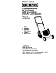
CRAFTSMAN
OWNER'S
MANUAL
6.25 HORSEPOWER
22" REAR DISCHARGE
POWER PROPELLED
ROTARY LAWN MOWER
Each Iawn mower has its own model number,,
glne has its own model number
MODEL NO.
917.377351
Each en,-
The model number for your lawn mower witl be found on a
decal attached to the rear of the lawn mower housing,
The model number lot your engine will be found on the
blower housing of the engine
All parts listed herein may be ordered from any Sears,
Roebuck and Co Service CentedDepartment
and most
Retaii Stores,
WHEN ORDERING REPAIR PARTS, ALWAYS GIVE THE
FOLLOWING INFORMATION:
IFYOU
NEED
REPAIR SERVICE
OR PARTS:
- PRODUCT-
LAWN MOWER
,, MODEL NUMBER-
917,377351
,' ENGINE MODEL Nee- 143,976252
FOR REPAIR SERVICE, CALL
THIS TOLL FREE NUMBER:
1-80O-4-REPAIR
(1-800-473t7247)
FOR REPLACEMENT PARTS
INFORMATION AND
ORDERING, CALL THIS
TOLL FREE NUMBER:
• PART NUMBER
* PART DESCRIPTION
Your Sears merchandise
has added vaiue when you
consider Sears has service units nationwide staffed with
Sears trained technicians,,
professional technicians
speclfiealty trained to _nsure that we meet our pledge to
you, we service wha_ We sell
1-80_)-FON-PART
(1_B00-366-7278)
28