1
THE DATACENTER IN A BOX SOLUTION
PERFORMANCE TEST: COMPARING DELL
AND HP BLADE SOLUTIONS
When you are investing in a converged infrastructure solution to meet the computing
needs of a department or remote or branch office of a large enterprise or a small to medium
enterprise datacenter, it is important to select wisely. While excellent performance is necessary,
other considerations—including how easy the solution is to set up and how much power it will
consume—cannot be overlooked in the decision.
We looked at two such server-network-storage solutions, one based on Dell EqualLogic
PS-M4110 Blade Arrays and the other based on HP StorageWorks D2200sb storage blades, to
see how they compared.
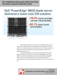
We found that the Dell converged datacenter in a box solution delivered 40 percent
greater IOPS performance, supported 48 percent more users, and had greater power efficiency
with 42 percent more users per watt of power consumed. Additionally, the Dell EqualLogic PSM4110 Blade Arrays took one-fifth the time to configure compared to the HP StorageWorks
D2200sb storage blades; and this assumes the engineer has familiarity with installing VMware®
ESXi™.
A datacenter in a box that excels in performance, supports more users, increases power
efficiency, and simplifies setup and configuration delivers benefits to your remote office—as
well as any similarly sized deployment—by better utilizing hardware and driving down operating
costs.
MAY 2012
A PRINCIPLED TECHNOLOGIES TEST REPORT
Commissioned by Dell Inc.
BETTER PERFORMANCE AND MORE USERS WITH EASIER SETUP AND
LESS COSTLY OPERATION
In our study, we examined the following blade server-network-storage solutions
to see how well they would meet the needs of a small to medium business (SMB) or
departmental computing solution within a large enterprise:
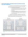
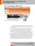
The Dell EqualLogic PS-M4110 solution: Three Dell PowerEdge™ M620
servers with two Dell EqualLogic PS-M4110 Blade Arrays, 2 Dell Force10
MXL 10/40GbE Blade Switches and 2 Dell PowerConnect™ M8024-k
10GbE switches
The HP D2200sb + VSA solution: Three HP ProLiant BL460c Gen8 blade
servers, two HP StorageWorks D2200sb storage blades, and two HP
ProLiant BL460c Gen8 partner blades to manage the storage, and four
HP Flex-10 10GbE switches
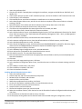
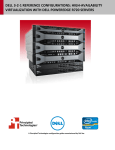
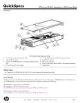
As Figure 1 shows, the Dell solution is considerably more streamlined, with
three server blades and two storage blades vs. the HP solution’s five servers and two
storage blades. Note that the Dell Force10 MXL blade switches are interlinked by a 40G
connection. All other connections in Figure 1 are 10G connections.
Figure 1. The Dell solution includes a total of five blades—two storage blades and three server blades, one for each of
the three workloads. The HP solution requires two additional partner blades to manage the storage, for a total of seven
blades.
The datacenter in a box performance test: Comparing Dell and HP
blade solutions
A Principled Technologies test report 2
Our testing had three components: first, we examined the setup process for
both solutions, recording the number of steps involved and the time required to
complete them. Next, we tested the performance of both solutions while running a
mixed workload including email, database, and collaboration applications. Finally, we
compared the amount of power the two solutions used while performing the workloads.
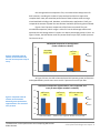
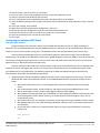
Figures 2 and 3 present comparisons of the factors we tested. They use
normalized comparisons, which assigns a value of 1.0 to the HP storage solution and
expresses the Dell storage solution’s results as a relative percentage greater or lesser. As
Figure 2 shows, the Dell solution took 55.6 percent fewer major steps, and 81.6 percent
less time to set up.
1.5
Normalized comparison of setup process
(lower numbers are better)
55% fewer
major steps
Figure 2. Compared to the HP
solution, the Dell solution took
less time and many fewer steps to
set up.
81% less
time
1.0
Dell
solution
HP
solution
0.5
0.0
Number of major steps
Time
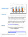
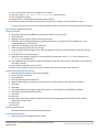
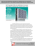
As Figure 3 shows, the Dell solution delivered 40.2 percent greater performance
and supported 48.1 percent more users and 42.7 percent more users per watt.
Normalized comparison of performance, users supported, and
users per watt (higher numbers are better)
2.0
48% more
users
40% more
IOPS
Figure 3. Compared to the HP
solution, the Dell solution
delivered greater performance,
supported more users and more
users per watt.
42% more users per
watt
1.5
Dell
solution
1.0
HP
solution
0.5
0.0
Performance (IOPS)
Number of users supported Number of users per watt
The datacenter in a box performance test: Comparing Dell and HP
blade solutions
A Principled Technologies test report 3
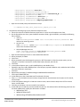
EASIER AND FASTER TO CONFIGURE
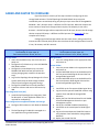
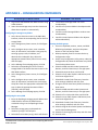
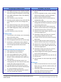
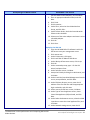
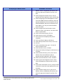
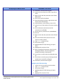
Figure 4 presents a summary of the steps involved in configuring the two
storage blade solutions. The Dell EqualLogic PS-M4110 Blade Array setup was
considerably more streamlined, taking only 8 major steps versus the HP StorageWorks
D2200sb + VSA’s 18 major steps—a difference of 55.6 percent. When we compare the
entire number of steps each storage solution requires, the disparity is even more
dramatic—the Dell storage solution required a total of 44 steps, whereas the HP storage
solution required 259 steps—a difference of 83.0 percent. (See Appendix E for the
complete set of steps.)
Configuring the Dell storage solution was also much faster, taking a total of 16
minutes and 46.7 seconds, 81.6 percent less time than the HP storage solution’s total of
1 hour, 30 minutes, and 58.2 seconds.
Dell EqualLogic PS-M4110 solution
Total number of major steps: 8
Total amount of time: 16 min, 46.7 sec
HP StorageWorks D2200sb + VSA solution
Total number of major steps: 18
Total amount of time: 1 hour, 30 min, 58.2 sec
Storage blades
Storage blades
1. Insert the two blade arrays into the chassis and
1. Insert the storage blades in the appropriate slots
power on.
and power on.
2. Configure the first blade array in the Dell M1000e
Partner blades
CMC Web interface.
2. Insert the partner blades in the appropriate slots
3. Configure the second blade array in the Dell
and power on.
M1000e CMC Web interface (and add to the
3. Use the BIOS RAID utility to set the RAID level for
existing storage group created in the previous
the first partner blade logical drive and the first
step)
storage blade logical drive.
4. Log into the EqualLogic Group Manager GUI from a
4. Use the BIOS RAID utility to set the RAID level for
system attached to the iSCSI storage network
the second partner blade logical drive and the
(Fabric-B) and configure the group settings.
second storage blade logical drive.
5. Configure the RAID level of the two members.
ESXi
6. Create the volumes and restrict iSCSI access by
5. Install ESXi on the first partner blade logical drive.
IQN.
6. Log into the first partner blade ESXi instance using
Host Integration Tools (HIT)
vSphere client and add the storage blade
7. Install the Dell EqualLogic Host Integration Tools
datastore.
for Microsoft on each application blade. This is
7. Deploy the first VSA VM and install the HP P4000
required for multipathing.
Centralized Management Console on your
iSCSI configuration on application blades and storage
management system.
8. Configure iSCSI initiator on each blade in Windows.
8. Set the first VSA VM IP address/networking.
Notes:
9. Install ESXi on the second partner blade logical
drive.
The Dell EqualLogic PS-M4110 is managed via a
10. Log into the second partner blade ESXi instance
Java application using a Web browser.
using vSphere client and add the storage blade
datastore.
11. Deploy the second VSA VM.
The datacenter in a box performance test: Comparing Dell and HP
blade solutions
A Principled Technologies test report 4
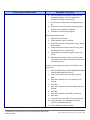
Dell EqualLogic PS-M4110 solution
Total number of major steps: 8
Total amount of time: 16 min, 46.7 sec
HP StorageWorks D2200sb + VSA solution
Total number of major steps: 18
Total amount of time: 1 hour, 30 min, 58.2 sec
12. Set the second VSA VM IP address/networking.
Failover Manager (FOM)
13. Deploy the FOM on an appropriate host server to
establish quorum between the two nodes.
HP Centralized Management Console
14. Log into the LeftHand Centralized Management
Console on the management system and add the
VSA nodes and FOM to the CMC.
15. Use the console to create a new management
group and cluster using the two VSA nodes and
FOM, and assign a virtual group IP.
16. Create the volumes, add the application servers,
and assign the relevant volumes to the application
servers.
Install HP multipathing software
17. Install HP DSM for MPIO software on each
application blade.
iSCSI configuration on application blades and storage
18. Configure iSCSI initiator on each application blade
in Windows.
Figure 4. Summary of steps required to configure the two solutions.
GREATER PERFORMANCE AND MORE USERS SUPPORTED
We used three different benchmarks to assess database, mail, and collaboration
performance: DVD Store version 2.1, Microsoft Load Generator 2010, and WSSDW
1.0.0.0 Beta respectively. To determine the maximum number of users supported by
each configuration in our tests, we used read latency for each storage solution as a
threshold to determine the supported users (and subsequently, the workload) for each
configuration. We simulated the same number of SharePoint and Exchange users, and
scaled the SQL Server workload while maintaining an acceptable read latency threshold
for each configuration.
As Figure 5 shows, the Dell solution supported more users than the HP solution
on all three workloads: 50.0 percent more Exchange mailboxes, 45.1 percent more SQL
Server users, and 49.3 percent more SharePoint users. The Dell datacenter in a box also
delivered 40.2 percent more total IOPS.
The datacenter in a box performance test: Comparing Dell and HP
blade solutions
A Principled Technologies test report 5
Number of supported users and total IOPS
2,000
1,500
Figure 5. The Dell datacenter in a box
supported as many as 50.0 percent
more users than the HP solution.
1,748
1,500
1,439
1,500
1,246
1,005
1,000
992
1,000
Dell
solution
HP
solution
500
0
SQL Server
(Users)
Exchange
(Mailboxes)
SharePoint
(Users)
Total
IOPS
Database testing
To create our real-world ecommerce workload, we used the DVD Store Version
2.1 benchmarking tool. DS2 models an online DVD store, where customers log in, search
for movies, and make purchases. DS2 reports these actions in orders per minute that
the system could handle, to show what kind of performance you could expect for your
customers. The DS2 workload also performs other actions, such as adding new
customers, to exercise the wide range of database functions you would need to run your
ecommerce environment.
We ran DS2 with 32 threads on both solutions, with a 0.12-second think time on
the Dell solution and a 0.18-second think time on the HP solution. This allowed us to
simulate a user completing one order approximately every 15 seconds on both
solutions, within the read latency requirements.
For more details about the DS2 tool, see
http://www.delltechcenter.com/page/DVD+Store.
Mail testing
To test the solutions’ mail server performance, we used the Microsoft Load
Generator 2010 (LoadGen) benchmark, performing tasks to simulate a heavy user
generating mail activity. For our workloads, we used the following settings:
Mailbox Profile: 250MB mailboxes
Action Profile: Very heavy
Client Type: Outlook_500
For more details about LoadGen, see
http://www.microsoft.com/downloads/details.aspx?FamilyId=DDEC1642-F6E3-4D66A82F-8D3062C6FA98&displaylang=en.
The datacenter in a box performance test: Comparing Dell and HP
blade solutions
A Principled Technologies test report 6
Collaboration testing
To simulate the traffic of SharePoint Server 2010 users, we used the WSSDW
1.0.0.0 Beta test. This test creates sample data, populates the server with it, and
simulates SharePoint Server users completing everyday tasks.
We used Visual Studio 2010 to execute the test workload, generating a realistic
user workload where each of the simulated heavy users performed a task every minute.
To do this, we set up the test to run 200 and 134 Visual Studio virtual users with an 8second think time in between each of the various tasks, to simulate 1,500 users for the
Dell solution and 1,005 users for the HP solution, respectively. The virtual user count
here was set to match the Exchange user count. The test workload then reports
throughput in tests per second.
For more details about SharePoint Server, see http://office.microsoft.com/enus/sharepoint-server-help/.
Detailed performance findings
In our testing, we used the read latency of each storage solution while running
the three applications to determine how many users each solution could support.
Typically, read latency should not exceed 20ms, so we used this as our threshold to
determine acceptable performance. A short response time is an important measure of
performance—it means that the users need to wait less time for the server to complete
a task. Figure 6 shows the average read and write latency in milliseconds, for the two
solutions under test.
Dell solution
HP solution
Read latency
(milliseconds)
11.7
20.0
Percentage decrease
from HP solution
41.5%
Write latency
(milliseconds)
5.1
14.5
Percentage decrease
from HP solution
64.8%
Figure 6. Read and write latency for the two solutions. Lower numbers are better.
Figure 7 shows the average throughput in IOPS each of the solutions delivered.
We conducted three test runs, and present the results from the median run. As Figure 7
shows, the Dell datacenter in a box solution increased overall throughput over the HP
solution by an average of 40.2 percent.
Throughput (IOPS)
Dell solution
HP solution
1,747.9
1,246.4
Average percentage increase over HP
solution
40.2%
Figure 7. Median throughput for the three applications running on the solutions. Higher numbers are better.
The datacenter in a box performance test: Comparing Dell and HP
blade solutions
A Principled Technologies test report 7
Figure 8 shows the number of users each solution supported while delivering an
acceptable read latency averaging less than 20ms for end users. The number of SQL
Server users supported, in this case, is determined by assuming that a user would
generate four SQL Server transactions per minute.
Users
SQL Server
Dell solution
HP solution
Exchange
Dell solution
HP solution
SharePoint
Dell solution
HP solution
Total across applications
Dell solution
HP solution
Percentage increase over HP solution
1,439
992
45.1%
1,500
1,000
50.0%
1,500
1,005
49.3%
4,439
2,997
48.1%
Figure 8. Number of users the solutions supported. Higher numbers are better.
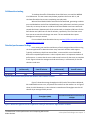
SUPPORT MORE USERS PER WATT
As Figure 9 shows, the two solutions consumed roughly the same amount of
power while performing the performance workloads described above, even though the
Dell solution supported as many as 1.5 times as many users. This translates to a usersper-watt advantage of 42.7 percent for the Dell datacenter in a box solution. (See Figure
10.)
Percentage increase over HP solution
Watts used
Dell solution
HP solution
Total number of users
Dell solution
HP solution
Users per watt
Dell solution
HP solution
1,263
1,214
4.0%
4,439
2,997
48.1%
1.17
0.82
42.7%
Figure 9. Number of users per watt the solutions supported.
The datacenter in a box performance test: Comparing Dell and HP
blade solutions
A Principled Technologies test report 8
Users per watt
(larger numbers are better)
1.4
1.2
1.0
Users
Figure 10. The Dell solution supported
more users per watt than the HP
solution.
1.17
0.82
0.8
Dell solution
0.6
HP solution
0.4
0.2
0.0
1
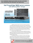
GREATER USABLE CAPACITY
More usable capacity in your server-storage solution provides more room to
grow with your business, either by giving applications more space as needed or
supporting additional blade servers using the existing storage infrastructure. This
translates directly to the total cost of ownership of your consolidated blade
server/storage deployment, or datacenter in a box. As Figure 11 shows, the Dell solution
provides 95.5 percent more usable capacity than the HP solution as configured. Each
Dell EqualLogic PS-M4110 Blade Array comes equipped with redundant controllers,
RAID technology to prevent data loss with failed drives, and redundant power supplies
that are available with the Dell M1000e blade chassis. For high availability configuration,
the redundant controllers in the Dell EqualLogic PS-M4110 arrays allow for spanning
data across the two arrays instead of the mirroring data across nodes required for high
availability by the single-controller-based HP storage arrays. This allows the Dell
datacenter in a box greater capacity, while still providing high availability at the
component level.
The datacenter in a box performance test: Comparing Dell and HP
blade solutions
A Principled Technologies test report 9
Usable capacity
(larger numbers are better)
6.0
5.22
5.0
4.0
TB
Figure 11. The Dell solution had greater
usable capacity than the HP solution.
2.67
3.0
Dell solution
HP solution
2.0
1.0
0.0
1
IN CONCLUSION
Throughout our testing, the Dell datacenter in a box solution based on Dell EqualLogic
PS-M4110 Blade Arrays had the advantage over the HP solution based on HP StorageWorks
D2200sb storage blades. Not only did the Dell solution deliver 40.2 percent better performance,
it required 55.6 percent fewer major steps to set up, supported 42.7 percent more users per
watt, and took one-fifth of the time to configure. Choosing such a complete datacenter in a box
solution can simplify infrastructure setup and configuration, boost performance, and save your
organization in data center costs over the life of the hardware.
The datacenter in a box performance test: Comparing Dell and HP
blade solutions
A Principled Technologies test report 10
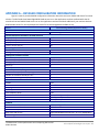
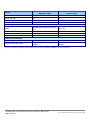
APPENDIX A – DETAILED CONFIGURATION INFORMATION
Figures 12 and 13 provide detailed configuration information about the test server blades and chassis from each
solution. The Dell used three PowerEdge M620 blade servers to run the applications and test workload while the HP
used three ProLiant BL460c blade servers to run the applications and test workload. Additionally, we used two ProLiant
BL460c blade servers for the required partner blades for the HP StorageWorks D2200sb arrays.
Server
Enclosure
Blade enclosure
General dimension information of blade enclosure
Height (inches)
Width (inches)
Depth (inches)
U size in server rack (U)
Power supplies of blade enclosure
Total number
Wattage of each power supply (W)
Cooling fans of blade enclosure
Total number
Dimensions (h x w) of each
Voltage (V)
Amps (A)
General processor setup
Number of processor packages
Number of cores per processor package
Number of hardware threads per core
System power management policy
CPU
Vendor
Name
Stepping
Socket type
Core frequency (GHz)
L1 cache
L2 cache
L3 cache
Platform
Vendor and model number
Motherboard model number
Motherboard chipset
BIOS name and version
BIOS settings
Dell PowerEdge M620 (Application blade)
Dell PowerEdge M1000e
17.25
19
29.5
10
6
2,360
9
3-1/4” x 3-1/4 “
12
5
2
6
2
Balanced
Intel
Xeon E5-2640
C2
Socket 2011 LGA
2.50
32 KB + 32 KB (per core)
256 KB (per core)
15 MB (shared)
Dell PowerEdge M620
0GVN4C
Intel ID3C00 Rev. 07
Phoenix ROM BIOS PLUS Version 1.10 1.1.2 (03/09/2012)
Default
The datacenter in a box performance test: Comparing Dell and HP
blade solutions
A Principled Technologies test report 11
Server
Memory modules
Total RAM in system (GB)
Number of types of memory modules
Vendor and model number
Type
Speed (MHz)
Speed in the system currently running @ (MHz)
Timing/latency (tCL-tRCD-iRP-tRASmin)
Size (GB)
Number of RAM modules
Chip organization
Hard disk
Vendor and model number
Number of disks in system
Size (GB)
Buffer size (MB)
RPM
Type
Operating system
Name
Build number
File system
Language
Network card/subsystem
Dell PowerEdge M620 (Application blade)
64
1
Samsung M393B1K70BH1-CH9
PC3-10600R
1,333
1,333
9-9-9-24
8
8
Double-sided
Dell MBE2147RC
2
146
16
15,000
SAS
Windows Server 2008 R2 Enterprise
7601
NTFS
English
Intel Ethernet X520 10GbE Dual Port KX4-KR Mezzanine
card
PCI
Intel 2.9.68.0 (12/5/2011)
Vendor and model number
Type
Driver
Figure 12. Detailed configuration information for the Dell PowerEdge M620 blades we used in our tests.
HP ProLiant BL460c Gen8
(Application blade)
Servers
Enclosure
Blade enclosure
General dimension information of
blade Enclosure
Height (inches)
Width (inches)
Depth (inches)
Power supplies of blade Enclosure
Total number
Wattage of each power supply (W)
HP ProLiant BL460c Gen8
(Partner blade)
HP BladeSystemc7000
HP BladeSystem c7000
17.4
17.6
32.0
17.4
17.6
32.0
6
2,450
6
2,450
The datacenter in a box performance test: Comparing Dell and HP
blade solutions
A Principled Technologies test report 12
HP ProLiant BL460c Gen8
(Application blade)
Servers
HP ProLiant BL460c Gen8
(Partner blade)
Cooling fans of blade Enclosure
Name and model number
Total number
Dimensions (h x w) of each
Voltage (V)
Amps (A)
General processor setup
Number of processor packages
Number of cores per processor
package
Number of hardware threads per core
System power management policy
CPU
Vendor
Name
Stepping
Socket type
Core frequency (GHz)
L1 cache
L2 cache
L3 cache
Platform
Vendor and model number
Motherboard model number
Motherboard revision number
BIOS name and version
BIOS settings
Memory modules
Total RAM in system (GB)
Vendor and model number
Type
Speed (MHz)
Speed in the system currently running
@ (MHz)
Timing/latency (tCL-tRCD-iRP-tRASmin)
Size (GB)
Number of RAM modules
Chip organization
Hard disk
Vendor and Model Number
Number of disks in the system
HP BL C Class Fan Turbine 486206001
10
3-1/2” x 7-1/2”
12
16.5
HP BL C Class Fan Turbine 486206-001
10
3-1/2” x 7-1/2”
12
16.5
2
2
6
6
12
Balanced
12
Balanced
Intel
Xeon E5-2640
C2
LGA2011
2.50
32 KB + 32 KB (per core)
256 KB (per core)
15 MB (shared)
Intel
Xeon E5-2640
C2
LGA2011
2.50
32 KB + 32 KB (per core)
256 KB (per core)
15 MB (shared)
HP ProLiant BL460c Gen8 Blade
ProLiant BL460c GEN8
07
HP I31 02/21/2012
Default
HP ProLiant BL460c Gen8 Blade
ProLiant BL460c GEN8
07
HP I31 02/21/2012
Default
64
Samsung M393B1K70BH1-CH9
PC3-10600R
1,333
32
Hynix HMT31GR7BFR4A-H9
PC3L-10600R
1,333
1,333
1,333
9-9-9-24
8
8
Double-sided
9-9-9-36
8
4
Double-sided
HP EH0146FARWD
2
HP EH0146FARWD
2
The datacenter in a box performance test: Comparing Dell and HP
blade solutions
A Principled Technologies test report 13
Servers
Size (GB)
Buffer size (MB)
RPM
Type
Operating system
Name
Build number
File system
Language
Network card/subsystem
Type
Vendor and model number
HP ProLiant BL460c Gen8
(Application blade)
146
16
15,000
SAS
Windows Server 2008 R2 Enterprise
SP1
7601
NTFS
English
Flex Module
HP FlexFabric 10 Gb dual port 554M
Adapter
HP ProLiant BL460c Gen8
(Partner blade)
146
16
15,000
SAS
ESXi 5.0.0
474610
Ext3
English
Flex Module
HP FlexFabric 10 Gb dual port 554M
Adapter
Figure 13. Detailed configuration information for the HP ProLiant BL460c Gen8blades we used in our tests.
The datacenter in a box performance test: Comparing Dell and HP
blade solutions
A Principled Technologies test report 14
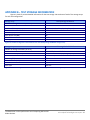
TEST STORAGE INFORMATION
Figures 14 and 15 provide detailed information for the test storage. We used two of each of the storage arrays
for each test configuration.
Storage array
Number of storage controllers per array
RAID level
Number of drives per array
Drive vendor and model number
Drive size (GB)
Drive buffer size (MB)
Drive RPM
Drive type
Dell EqualLogic PS-M4110
2
50
14 (10 active data drives, 2 parity, 2 spares)
Dell MK3001GRRB
300
32
15,000
6Gb SAS
Figure 14. Detailed configuration information for the two Dell EqualLogic PS-M4110 storage arrays.
Storage array
Number of storage controllers per array
RAID level
Number of drives per array
Drive vendor and model number
Drive size (GB)
Drive buffer size (MB)
Drive RPM
Drive type
HP StorageWorks D2200sb
1
Disk RAID 5; Network RAID 10
12 (10 active data drives, 1 parity, 1 spare)
HP EH300FBQDD
300
64
15,000
6Gb SAS
Figure 15. Detailed configuration information for the two HP StorageWorks D2200sb storage arrays.
The datacenter in a box performance test: Comparing Dell and HP
blade solutions
A Principled Technologies test report 15
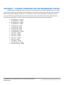
APPENDIX C – STORAGE CONFIGURATION FOR PERFORMANCE TESTING
We followed the configuration steps for each of the storage solutions as outlined in Appendix E. For our testing,
we placed the Failover Manager (FOM) for the HP D2200sb + VSA solution directly on one of the two nodes to establish
quorum without affecting power utilization. In a real-world environment, you should deploy the FOM onto another
server connected to the iSCSI network to ensure that it remains active in the event that one of the VSA nodes loses
connectivity or goes offline. For each solution, we configured the storage with the volumes listed below.
Exchange Data 1 – 150GB
Exchange Data 2 – 150GB
Exchange Data 3 – 150GB
Exchange Data 4– 150GB
Exchange Log 1– 10GB
Exchange Log 2– 10GB
Exchange Log 3– 10GB
Exchange Log 4– 10GB
Exchange Backup – 500GB
SQL Data 1 – 100GB
SQL Data 2 – 100GB
SQL Data 3 – 100GB
SQL Data 4 – 100GB
SQL Logs – 100GB
SQL Backup – 200GB
SharePoint Data – 200GB
SharePoint Backup – 200GB
The datacenter in a box performance test: Comparing Dell and HP
blade solutions
A Principled Technologies test report 16
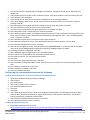
APPENDIX D – SERVER CONFIGURATION FOR PERFORMANCE TESTING
For performance testing, we configured each of the three blade servers in each solution to run one of the
applications (SQL Server, Exchange Server, and SharePoint Server) with the data for each application on the respective
blade storage solution. For our benchmark test clients and domain controller, we configured virtual machines on a
separate server, ensuring that each virtual machine had ample hardware resources. We also configured the client VM
host servers with 10G network adapters to connect to the 10G switches in each solution. See Figure 1 for a detailed
diagram showing our network configurations. For each solution, we had a single domain controller VM, a DVD store
client VM, a WSSDW client VM, and ten LoadGen client VMs distributing the user workload evenly.
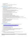
Installing the operating system on the application blade servers
1.
2.
1.
2.
3.
4.
5.
6.
7.
8.
9.
10.
11.
12.
Insert the installation DVD for Windows Server 2008 R2 SP1 Enterprise into the DVD drive.
At the Language Selection Screen, click Next.
Click Install Now.
Select Windows Server 2008 R2 Enterprise (Full Installation), and click Next.
Click the I accept the license terms checkbox, and click Next.
Click Custom.
Click Next.
At the User’s password must be changed before logging on warning screen, click OK.
Enter the desired password for the administrator in both fields, and click the arrow to continue.
At the Your password has been changed screen, click OK.
Connect the machine to the Internet, and install all available Windows updates. Restart as necessary.
Enable remote desktop access.
Change the hostname and reboot when prompted.
Set up networking:
a. Click StartControl Panel, right-click Network Connections, and choose Open.
b. Right-click the NIC assigned to the private network, and choose Properties.
c. Select TCP/IP (v4), and choose Properties.
d. Set the IP address, subnet, gateway, and DNS server for the virtual NIC, which will handle outgoing server
traffic. Click OK, and click Close.
e. Repeat steps b-d for the iSCSI NIC and apply the appropriate IP address.
13. After creating and configuring the storage volumes on the storage level and in iSCSI initiator:
a. Click the Server Manager icon in the taskbar.
b. In the left pane, expand Storage, and click Disk Management.
c. Right-click the first volume, and choose Initialize Disk.
d. In the right pane, right-click the volume and choose New Simple VoIume…
e. At the Welcome screen, click Next.
f. At the Specify Volume Size screen, leave the default selection, and click Next.
g. At the Assign Drive Letter or Path screen, choose a drive letter, and click Next.
h. At the Format Partition screen, leave the defaults and click Next.
i. At the Completing the New Simple Volume Wizard screen, click Finish.
j. Repeat steps c through i for the remaining volumes.
Configuring the first application server for SQL 2012
Installing Microsoft SQL Server 2012
1. Insert the installation DVD.
The datacenter in a box performance test: Comparing Dell and HP
blade solutions
A Principled Technologies test report 17
2. Click Run SETUP.EXE. If Autoplay does not begin the installation, navigate to the SQL Server 2012 DVD, and
double-click.
3. If the installer prompts you with a .NET installation prompt, click Yes to enable the .NET Framework Core role.
4. In the left pane, click Installation.
5. Click New SQL Server stand-alone installation or add features to an existing installation.
6. At the Setup Support Rules screen, wait for the rule check to complete. If there are no failures or relevant
warnings, click OK.
7. Select the Specify a free edition and select Evaluation from the drop-down menu. Click Next.
8. Click the checkbox to accept the license terms, and click Next.
9. If no failures are displayed after the setup support files are installed, click Next.
10. At the Setup Role screen, choose SQL Server Feature Installation.
11. At the Feature Selection screen, select Database Engine Services, Full-Text and Semantic Extractions for Search,
Client Tools Connectivity, Client Tools Backwards Compatibility, Management Tools – Basic, and Management
Tools – Complete. Click Next.
12. At the Installation Rules screen, click Next once the check completes.
13. At the Instance configuration screen, leave the default selection of default instance, and click Next.
14. At the Disk Space Requirements screen, click Next.
15. At the Server Configuration screen, check that NT Service\SQLSERVERAGENT is selected for SQL Server Agent,
and that NT Service\MSSQLSERVER is selected for SQL Server Database Engine. Click Next.
16. Assuming no failures are displayed, click Next.
17. At the Database Engine Configuration screen, select Mixed Mode.
18. Enter and confirm a password for the system administrator account.
19. Click Add Current user. This may take several seconds.
20. Click Next.
21. At the Error and usage reporting screen, click Next.
22. At the Installation Configuration Rules screen, check that there are no failures or relevant warnings, and click
Next.
23. At the Ready to Install screen, click Install.
24. After installation completes, click Close.
25. Close the installation window.
Configuring the second application server for Exchange
Installing .NET Framework 3.5.1 Features and Internet Information Services
1. Select StartAdministrative ToolsServer Manager.
2. Click Features.
3. Click Add Features.
4. Select .NET Framework 3.5.1 Features
5. Click Add Required Role Services.
6. Click Next.
7. Click Next.
8. At the Select Role Services screen, select the IIS 6 Metabase Compatibility, IIS 6 Management Console, Basic
Authentication, Windows Authentication, Digest Authentication, Static content compression, and Dynamic
content Compression checkboxes, and click Next.
9. At the Confirm Installation Selections screen, click Install.
10. At the Installation Results screen, click Close.
Installing Microsoft Filter Pack 2.0
1. Download the Microsoft Filter Pack 2.0.
(http://www.microsoft.com/downloads/en/details.aspx?FamilyID=5cd4dcd7-d3e6-4970-875e-aba93459fbee)
The datacenter in a box performance test: Comparing Dell and HP
blade solutions
A Principled Technologies test report 18
2. Run FilterPackx64.EXE.
3. Click Next.
4. Click I accept the terms in the License Agreement, and click Next.
5. When the installation is complete, click OK.
Installing Exchange Server 2010
Click Start, type services and press Enter.
Right-click the Net.Tcp Port Sharing service, and click Properties.
Change the Net.Tcp Port Sharing startup type to Automatic, and click OK.
Open command prompt and type ServerManagerCmd –i RSAT-ADDS, and press Enter.
Reboot the server.
Insert the installation DVD and click Setup.EXE when prompted.
The installer should consider steps 1 and 2 complete, and gray them out.
Click the link for Step 3: Choose Exchange Language Option.
Click Install only languages from the DVD.
Click the link for Step 4: Install Microsoft Exchange Server 2010 SP1.
Click Next to go past the introduction screen.
Accept the license agreement, and click Next.
Select No for error reporting, and click Next.
Select Typical Exchange Server Installation, and click Next.
Leave the organization name at default (First Organization), and click Next.
At the question about client computers running Outlook 2003 and earlier, select Yes, and click Next.
Click Next to accept defaults for Configure Client Access server external domain.
At the Customer Experience Improvement Program screen, select I don’t want to join the program at this time,
and click Next.
19. If a warning about a lack of SMTP appears after the check finishes, ignore it.
20. Click Install to start the installation process.
21. Once installation is complete, click Finish.
22. Click OK when prompted to reboot.
23. Click Close.
24. Click Yes to confirm exit.
25. Reboot the server.
Installing SP2 for Microsoft Exchange 2010
1. Download Service Pack 2 for Microsoft Exchange 2010 (Exchange2010-SP2-x64.exe) from
http://www.microsoft.com/download/en/details.aspx?id=28190 to c:\SP2.
2. Double-click the downloaded file to extract the installation files.
3. Click OK to accept the destination directory for the extracted files.
4. Double-click setup.exe to launch the installer.
5. Click Install Microsoft Exchange Server upgrade.
6. At the Introduction screen, click Next.
7. Accept the terms in the license agreement, and click Next. The Readiness Checks will now run.
8. Install any roles in Server Manager that the Readiness Checks prompt you to install.
9. When the checks successfully complete, click Upgrade.
10. Click Finish, and reboot.
Server 2010 roles
1. Select StartAll ProgramsMicrosoft Exchange Server 2010Exchange Management Console.
2. In the left pane, click Microsoft Exchange On-Premises.
1.
2.
3.
4.
5.
6.
7.
8.
9.
10.
11.
12.
13.
14.
15.
16.
17.
18.
The datacenter in a box performance test: Comparing Dell and HP
blade solutions
A Principled Technologies test report 19
3.
4.
5.
6.
7.
In the left pane, expand Organization Configuration, and select Hub Transport.
In the action pane on the far right, select New Send Connector.
Name the send connector SMTP, select the intended use as Internet, and click Next.
In the Address space screen, click Add.
In the SMTP Address Space screen, type * as the address, ensure that the installer has checked Include all
subdomains, and click OK.
8. Click Next.
9. Accept defaults for the next two pages by clicking Next.
10. At the New Connector page, click New to create the connector.
11. Click Finish to close the New SMTP Send Connector wizard.
Configuring the Exchange Server 2010 Mailbox role
Before completing this section, create an additional three mailbox databases so that you have four total, and
complete these steps on each mailbox database.
1.
2.
3.
4.
5.
6.
7.
8.
9.
10.
11.
12.
13.
14.
15.
16.
17.
18.
19.
20.
21.
22.
23.
24.
Select StartAll ProgramsMicrosoft Exchange Server 2010Exchange Management Console.
In the left pane, expand Organization Configuration, and click Mailbox.
Click the Database Management tab.
Right-click Mailbox Database, and select Properties.
Select the Maintenance tab.
Check the Enable circular logging box.
Check the box beside This database can be overwritten by a restore.
Next to Maintenance interval, click Customize.
Remove all blue from the boxes so the system will not perform maintenance, and click OK.
Click OK.
Click OK to any warnings about circular logging being applied after the database is remounted.
On the far right panel, click Move Databases.
Change the Database file and Log folder path locations to E:\Database\(filename) and F:\Maillogs respectively,
and click Move.
If the application prompts you to dismount, click Yes.
Click Finish.
Right-click Public Folder Database, and select Properties.
Check the Enable circular logging checkbox and uncheck the ESE scanning checkbox.
Click Customize next to Maintenance interval.
Remove all blue from the boxes so the system will not perform maintenance, and click OK.
Click OK.
On any warnings about circular logging being applied after the database is remounted, click OK.
Click Move Database on the far right panel.
Change the Database file and Log folder path locations to E:\Database\(filename) and F:\Publiclogs respectively,
and click Move.
25. If the application prompts you to dismount, click Yes.
26. Click Finish.
Configuring the third application server for SharePoint
We installed a separate instance of SQL Server 2012 for our SharePoint databases. This prevented creating an
unnecessary bottleneck by having WSSDW and DVD Store running against the same instance of SQL on the same
application server.
Installing Microsoft SQL Server 2012
The datacenter in a box performance test: Comparing Dell and HP
blade solutions
A Principled Technologies test report 20
1. Insert the installation DVD.
2. Click Run SETUP.EXE. If Autoplay does not begin the installation, navigate to the SQL Server 2012 DVD, and
double-click.
3. If the installer prompts you with a .NET installation prompt, click Yes to enable the .NET Framework Core role.
4. In the left pane, click Installation.
5. Click New SQL Server stand-alone installation or add features to an existing installation.
6. At the Setup Support Rules screen, wait for the rule check to complete. If there are no failures or relevant
warnings, click OK.
7. Select the Specify a free edition and select Evaluation from the drop-down menu. Click Next.
8. Click the checkbox to accept the license terms, and click Next.
9. If no failures are displayed after the setup support files are installed, click Next.
10. At the Setup Role screen, choose SQL Server Feature Installation.
11. At the Feature Selection screen, select Database Engine Services, Full-Text and Semantic Extractions for Search,
Client Tools Connectivity, Client Tools Backwards Compatibility, Management Tools – Basic, and Management
Tools – Complete. Click Next.
12. At the Installation Rules screen, click Next after the check completes.
13. At the Instance configuration screen, leave the default selection of default instance, and click Next.
14. At the Disk Space Requirements screen, click Next.
15. At the Server Configuration screen, check that NT Service\SQLSERVERAGENT is selected for SQL Server Agent,
and that NT Service\MSSQLSERVER is selected for SQL Server Database Engine. Click Next.
16. Assuming there are no failures, click Next.
17. At the Database Engine Configuration screen, select Mixed Mode.
18. Enter and confirm a password for the system administrator account.
19. Click Add Current user. This may take several seconds.
20. Click the Data Directories tab and enter the appropriate drive and folder to which you eventually deploy the
SharePoint databases.
21. Click Next.
22. At the Error and usage reporting screen, click Next.
23. At the Installation Configuration Rules screen, check that there are no failures or relevant warnings, and click
Next.
24. At the Ready to Install screen, click Install.
25. After installation completes, click Close.
26. Close the installation window.
Installing Microsoft SharePoint Server 2010
1. Insert the installation DVD.
2. Launch setup.exe, and click Install software prerequisites.
3. Review the list of software, and click Next.
4. Accept the EULA, and click Next.
5. When the prerequisites finish installing, click Finish.
6. On the main SharePoint installation menu, click Install SharePoint Server.
7. Enter your product license key, and click Continue.
8. Accept the EULA, and click Continue.
9. Choose the Complete server type, and click Install.
10. When the installation finishes, check the box for Run the SharePoint Products Configuration Wizard now, and
click Close.
11. On the Welcome to SharePoint Products screen, click Next.
12. On the pop-up warning about services that will need to be restarted during the configuration, click Yes.
The datacenter in a box performance test: Comparing Dell and HP
blade solutions
A Principled Technologies test report 21
13.
14.
15.
16.
17.
18.
19.
20.
21.
22.
23.
Choose Create a new server farm, and click Next.
Enter the name of your existing database instance on the same application server.
Specify a username and password, and click Next.
Enter a passphrase into the Passphrase and Confirm Passphrase fields, and click Next.
Leave the default settings on the Configure SharePoint Central Administration Web Application screen, and click
Next.
Verify your settings, and click Next.
When the wizard has completed the configuration, click Finish.
Choose Run the farm configuration wizard on the Central Administration site.
Choose the services you wish to include in your server farm, and click Next.
Enter the specifications for the new site, and click OK.
Click Finish.
Configuring the database (DVD Store)
Data generation overview
We generated the data using the Install.pl script included with DVD Store version 2.1 (DS2), providing the
parameters for our 100GB database size and the database platform on which we ran: Microsoft SQL Server. We ran the
Install.pl script on a utility system running Linux. The database schema was also generated by the Install.pl script.
After processing the data generation, we transferred the data files and schema creation files to a Windowsbased system running SQL Server 2008 R2 SP1. We built the 100GB database in SQL Server 2008 R2, and then performed
a full backup, storing the backup file on the C: drive for quick access. We used that backup file to restore to the servers
between test runs. We performed this procedure once.
The only modification we made to the schema creation scripts were the specified file sizes for our database. We
explicitly set the file sizes higher than necessary to ensure that no file-growth activity would affect the outputs of the
test. Besides this file size modification, the database schema was created and loaded according to the DVD Store
documentation. Specifically, we followed the steps below:
1. We generated the data and created the database and file structure using database creation scripts in the DS2
download. We made size modifications specific to our 100GB database and the appropriate changes to drive
letters.
a. We transferred the files from our Linux data generation system to a Windows system running SQL
Server.
b. We created database tables, stored procedures, and objects using the provided DVD Store scripts.
c. We set the database recovery model to bulk-logged to prevent excess logging.
d. We loaded the data we generated into the database. For data loading, we used the import wizard in SQL
Server Management Studio. Where necessary, we retained options from the original scripts, such as
Enable Identity Insert.
e. We created indices, full-text catalogs, primary keys, and foreign keys using the database-creation scripts.
f. We updated statistics on each table according to database-creation scripts, which sample 18 percent of
the table data.
g. On the SQL Server instance, we created a ds2user SQL Server login using the following Transact SQL
(TSQL) script:
USE [master]
GO
The datacenter in a box performance test: Comparing Dell and HP
blade solutions
A Principled Technologies test report 22
CREATE LOGIN [ds2user] WITH PASSWORD=N’’,
DEFAULT_DATABASE=[master],
DEFAULT_LANGUAGE=[us_english],
CHECK_EXPIRATION=OFF,
CHECK_POLICY=OFF
GO
h.
i.
j.
k.
We set the database recovery model back to full.
We created the necessary full text index using SQL Server Management Studio.
We created a database user and mapped this user to the SQL Server login.
We then performed a full backup of the database. This backup allowed us to restore the databases to a
pristine state relatively quickly between tests.
Running the DVD Store tests
We created a series of batch files, SQL scripts, and shell scripts to automate the complete test cycle. DVD Store
outputs an orders-per-minute metric, which is a running average calculated through the test. In this report, we report
the last OPM result reported by each client/target pair.
Each complete test cycle consisted of the general steps listed below. For each scenario, we ran three test cycles,
and reported the median outcome.
1.
2.
3.
4.
5.
6.
Clean up prior outputs from the server and all client driver systems.
Drop all databases from the test servers.
Restore all databases on all test servers.
Reboot the server and all client systems.
Let the test server idle until the power utilization settled.
Start the DVD Store driver on all respective clients.
We used the following DVD Store parameters for testing the servers in this study:
ds2sqlserverdriver.exe --target=<target_IP> --ramp_rate=10 –
warmup_time=10 --run_time=30 --n_threads=20 --db_size=100GB -think_time=0.12 (Dell) or 0.18 (HP)
Installing and configuring the Exchange 2010 mail test clients (LoadGen)
For our testing, we used 10 virtual client machines to distribute the LoadGen workload evenly for each of the
solutions. To create the mail clients, we installed several software components. First, we made sure to statically assign
an IP address for each client. We followed this process for each installation:
Installing Windows Server 2008 R2 SP1 Enterprise Edition
1. Insert the installation DVD for Windows Server 2008 R2 SP1 Enterprise into the DVD drive.
2. At the Language Selection Screen, click Next.
3. Click Install Now.
4. Select Windows Server 2008 R2 Enterprise (Full Installation), and click Next.
5. Click the I accept the license terms checkbox, and click Next.
6. Click Custom.
7. Click Next.
8. At the User’s password must be changed before logging on warning screen, click OK.
9. Enter the desired password for the administrator in both fields, and click the arrow to continue.
The datacenter in a box performance test: Comparing Dell and HP
blade solutions
A Principled Technologies test report 23
10.
11.
12.
13.
14.
At the Your password has been changed screen, click OK.
Click Start, type change power-saving settings and press Enter.
Click Change plan settings.
Change the Turn off the display drop-down menu to Never.
Click Save changes, and close the Power Options, Screen Saver Settings, and Personalization screens.
To set up this server, we had to install several additional software components. The following subsections detail
the necessary installation processes.
Joining the domain
1. Select StartControl PanelNetwork ConnectionsLocal Area Connection.
2. Click Properties.
3. Highlight Internet Protocol (TCP/IP), and click Properties.
4. Select the Use the following DNS server addresses radio button, and enter the IP of the DNS server in the
Preferred DNS server field. Click OK.
5. Right-click My Computer, and select Properties.
6. Under the Computer Name tab, click Change.
7. In the Computer Name Changes screen, under the Member of section, select the Domain radial box, and type
test.local
8. Select OK to start joining the domain.
9. When the screen appears asking for a person qualified on the domain, type Tester as the username and
Password1 as the password.
10. At the Welcome pop-up window and the window warning that you must reset the computer for the changes to
take effect, click OK.
11. At the System Properties screen, click OK.
12. When a pop-up appears asking if you want to restart now, click Yes to restart your computer.
Installing Internet Information Services
1. Click StartAdministrative ToolsServer Manager.
1. On the left pane, click Roles.
2. Click Add Roles.
3. Click the Application Server checkbox.
4. When the Add features required for Application Server? screen appears, click Add Required Features.
5. Click Next.
6. Click Next.
7. At the Select Role Services page for Application Server, click the Web Server (IIS) Support checkbox.
8. Click Add Required Support Role Services.
9. Click Next.
10. Click Next.
11. At the Select Role Services page for Web Server (IIS), click IIS 6 Management Compatibility, ASP, and CGI
checkboxes; and click Next.
12. Click Install.
13. Click Close.
Installing Load Generator
Download and install Load Generator using all defaults.
Preparing Load Generator
1. Log into the mail client using the tester account.
The datacenter in a box performance test: Comparing Dell and HP
blade solutions
A Principled Technologies test report 24
2.
3.
4.
5.
6.
7.
8.
9.
10.
11.
12.
13.
14.
Select StartAll ProgramsMicrosoft ExchangeExchange Load Generator 2010.
When the Load Generator screen appears, select Start a new test.
Select Create a new test configuration, and click Continue.
Change the total length of simulation to 1 hour and 15 minutes.
In the Specify test settings screen, type Password1 as the Directory Access Password and Mailbox Account
Master Password, and click Continue with recipient management.
Make 250 users per mailbox (1,000 total) for the HP or 375 users per mailbox (1,500 total) for the Dell in the
Mailbox Database, and click Continue.
To accept defaults for Advanced recipient settings, click Continue.
In the Specify test user groups screen, select the plus sign to add a user group.
Change the Client Type to Outlook_500, the Action Profile to Average, and the Mailbox size to 250 MB.
Check the PreTestLogon checkbox, and click Continue.
In Remote configurations, enter the computer names of all of the test clients, check the checkbox to enable
distributing the workload, and click Continue.
Click Save the configuration file as, and name it testcfg.xml
After saving the configuration file, check the Initialize public store as well checkbox, and click Start the
initialization phase (recommended before running the test).
Backing up the mail databases
On the Exchange server virtual machine, once we set up the LoadGen client and created its initial mail database,
we backed up the databases so we can have clean copies for each test.
1. Select StartAll ProgramsMicrosoft Exchange Server 2010Exchange Management Console in the mail
server.
2. In the left pane, expand Organization Configuration and Mailbox.
3. In the right pane, right-click each of the four Mailbox Databases, and select Dismount Database from the menu.
4. At the Do you want to continue? pop-up message, click Yes.
5. Right-click Public Folder Database, and select Dismount Database from the menu.
6. At the Do you want to continue? pop-up message, click Yes. The red arrow appears when you have dismounted
the Public Folder Store.
7. Using Windows Explorer, create a new folder: E:\backup\
8. With Windows Explorer, copy all database and public folder files from E:\Database to E:\backup. This process
may take several minutes.
9. Close Windows Explorer.
10. In the Exchange Management Console, right-click each of the four Mailbox Databases, and select Mount
Database from the menu.
11. Right-click the Public Folder Database, and select Mount Database from the menu.
12. Close the Exchange Management Console.
Preparing the SharePoint test client
Install Windows Server 2008 SP1 with current updates.
Installing Microsoft Visual Studio 2010 Ultimate Edition
1. Download vs_ultimateweb.exe from www.microsoft.com/download/en/details.aspx?id=12752
2. Double-click vs_ultimateweb.exe to run the installer.
3. Uncheck the box beside Yes, send information about my computer, and click Next.
4. If you see a pop-up requiring a Windows Imaging component, click the Windows Imaging Component is
Required link.
5. Click Download on the appropriate Imaging component, and choose Run.
6. Accept the EULA, and click Next.
The datacenter in a box performance test: Comparing Dell and HP
blade solutions
A Principled Technologies test report 25
7.
8.
9.
10.
11.
12.
13.
14.
Close the pop-up window.
Click Next.
Accept the EULA, review the components to be installed, and click Next.
Choose the Full installation and location for the install, and click Install.
Click Finish.
Reboot the machine.
Click StartAll ProgramsMicrosoft Visual Studio 2010Microsoft Visual Studio 2010.
When prompted, select General Development Settings and click Start Visual Studio.
Setting up and running WSSDW 1.0.0.0 Beta
1. Complete the following steps on the Domain Controller machine:
a. Click StartAdministrative ToolsActive Directory Users and Computers.
b. Right-click the domain name and select NewGroup.
c. Enter testdomaingroup1 for the group name.
d. Repeat steps a through c and create another group named testdomaingroup2
2. Download the following from http://sptdatapop.codeplex.com/releases/view/1141
To the SharePoint 2010 VM
o WSS Data Population Tool RunTime.zip
o WSS Data Population Tool.chm
o WSS Data Population Tool Sample.zip
To the SharePoint 2010 test client
o WSS Performance Load Tests
3. Complete the following steps on the SharePoint 2010 VM:
a. Extract the contents of WSS Data Population Tool RunTime.zip and WSS Data Population Tool Sample.zip.
b. Copy the contents of both extracted .zip folders (WSS Data Population Tool Run Time and WSS Data
Population Tool Sample) into the root of C:
4. Download SharePtServerDeployment.doc from http://www.microsoft.com/enus/download/details.aspx?id=10009 and place it into the c:\wssdw folder.
a. Rename WSS Data Population Sample File.xml to WSS_Data_Population_Sample_File.xml so that
there are no spaces in the name. This allows the script to execute from the command prompt.
b. Right-click WSS_Data_Population_Sample_File.xml and click Edit to open the document in Notepad. Scroll
down to line 55 and remove “.txt” from the document name in the destfile parameter. Then, change any
applicable parameters to match the following:
<setproperty
<setproperty
<setproperty
<setproperty
<setproperty
<setproperty
<setproperty
<setproperty
<setproperty
<setproperty
<setproperty
<setproperty
<setproperty
NumberOfSiteCollections="100" />
SiteNameBase="testsite" />
NumberOfGroups="2" />
GroupNameBase="testgroup" />
TargetDomain="test.local" />
DomainGroupRoot="testdomaingroup" />
DomainUserName="administrator" />
DomainUserPassword="Password1" />
DesignerGroup="design" AdminGroup="full control" />
NumberOfDocumentLibraries="10" />
DocumentLibraryNameBase1="testdoclib_A" />
NumberOfDocuments="10" />
SourceFileLocation="c:\wssdw\SharePtServerDeployment.doc"
/>
The datacenter in a box performance test: Comparing Dell and HP
blade solutions
A Principled Technologies test report 26
<setproperty
<setproperty
<setproperty
<setproperty
<setproperty
<setproperty
<setproperty
DestFile="test.doc" />
NumberOfFileVersions="3" />
DocumentLibraryNameBase2="testdoclib_B" />
NumberOfLists="10" />
ListNameBase="testlist" />
NumberOfListItems="20" />
webpartpath="webpartpagesfolder" />
c. Open the command prompt and execute the script:
C:\>WSSDW.exe WSS_Data_Population_Sample_File.xml
5. Complete the following steps on the SharePoint 2010 test client:
a. Extract the contents of WSS Performance Load Test to C: drive on the SharePoint test client.
b. On the SharePoint test client, open the WSSTransactions folder, right-clickEdit, and modify the following
files as follows:
users.csv
Under username,password enter test.local\administrator,Password1 and
remove the remaining entries.
serverUrl.csv
Under serverUrl replace http://server with http://spserver to match the server
name of the SharePoint 2010 VM.
HierarchyManagerUsers.csv
Under username,password replace domain\username,password with
test.local\administrator,Password1
c. Open the WssTestProject.sln file in Visual Studio 2010 Ultimate.
d. When prompted, click Next.
e. Click Finish.
f. When prompted, leave the Retarget the project to .NET Framework 4. After the project opens, you can
retarget it to another Framework or Profile radio button selected, and click OK.
g. Click Close.
h. In the Solution Explorer pane, scroll to WSSDispForm, and double-click it.
i. Expand the top menu under WSSDispForm in the left pane, expand Validation rules, and delete the FindText
entry that references mysite.aspx.
j. Click Save.
k. Repeat steps h through j for WSSHomePage and WSSSmallDocLibAllItems.
l. Click ProjectAdd Load Test.
m. At the Welcome to the Create New Load Test Wizard, click Next.
n. Enter Test for the load test scenario name, change the think time between test iterations to 45 seconds,
and click Next.
o. At the Load pattern settings for a load test scenario screen, select Constant load, enter 125 for the User
Count, and click Next.
p. Click Next at the Select a test mix model for the load test.
q. At the Add test to a load test scenario and edit the test mix, click Add and select the following tests from the
list below. Additionally, modify the distribution as follows:
WSSDispForm 10%
WSSDocHTTPFetch 30%
WSSHomePage 20%WSSSmallDocLibAllItems 30%
The datacenter in a box performance test: Comparing Dell and HP
blade solutions
A Principled Technologies test report 27
WSSPutDocumentCoded 10%
r. Click OK.
s. At the Network types screen, select LAN, and click Next.
t. At the Browser screen, click Next.
u. At the Specify computers to monitor with counters sets during load test run screen, click Next.
v. At the Review and edit run settings for load test screen, enter 15 minutes for the Warm-up duration, enter
30 minutes for Run duration, 15 minutes for the Cool down duration, and click Finish.
6. To ensure that the WSSDW workload evenly selecta different SharePoint sites at random, create .csv lists of a
number of categories within each test and addthe following parameters to each:
WSSD WSSDispForm: Site name, list name, and list IDs.
WSSDocHTTPFetch: Site name, doc revision, document library name, and document name.
WSSHomePage: Site name
WSSSmallDocLibAllItems: Site name, and document library name
WSSPutDocumentCoded: Site name
7. Add the following lines of code to the WSSPutDocumentCoded test:
[DeploymentItem("officeservertransactions\\siteNames.csv",
"officeservertransactions")]
[DataSource("Sites", "Microsoft.VisualStudio.TestTools.DataSource.CSV",
"|DataDirectory|\\officeservertransactions\\siteNames.csv",
Microsoft.VisualStudio.TestTools.WebTesting.DataBindingAccessMethod.Random,
Microsoft.VisualStudio.TestTools.WebTesting.DataBindingSelectColumns.SelectO
nlyBoundColumns, "siteNames#csv")]
[DataBinding("Sites", "siteNames#csv", "siteName",
"Sites.siteNames#csv.siteName")]
At the "WebTestRequest request1" line, add:
+ this.Context["Sites.siteNames#csv.siteName"].ToString() +
Running the test
To run the test, we staggered the workload, allowing each benchmark time to warm up prior to measuring the
performance and latency on each of the solutions.
1. Begin running the LoadGen benchmark. LoadGen is set to run for 1 hour and 15 minutes, with a 15-minute
allotted warm-up period, 30-minute time of recorded latency, and 15-minute cool-down period.
2. Immediately after beginning the LoadGen benchmark, start the WSSDW workload. This workload is set to run for
1 hour and 15 minutes, with a 15-minute warm up period, 30-minute run period, and 15-minute cool-down
period.
3. Five minutes after LoadGen and WSSDW begin, start the DVD Store benchmark. DVD Store is set to warm up for
10 minutes, and then run for 30 minutes of recorded performance to coincide with LoadGen.
The datacenter in a box performance test: Comparing Dell and HP
blade solutions
A Principled Technologies test report 28
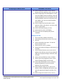
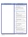
APPENDIX E – CONFIGURATION COMPARISON
Dell EqualLogic PS-M4110 solution
1. Log into the Dell M1000e CMC Web interface using
a Web browser.
2. Insert the two storage arrays into the chassis and
allow them to power on automatically.
Configuring the storage array blades
1. At the Server Overview screen in the CMC Web
interface, select the corresponding slot for the first
storage blade.
2. At the Storage Array Status screen, click Configure
Array.
3. At the Configure Array screen, enter a member
name, IP information, and create a new group by
entering a group name, IP address, and
administrator credentials. Also, select the
appropriate network fabric (Fabric B in our case),
and click Apply.
4. At the Message from webpage popup, click OK.
5. Select the corresponding slot for the second
storage blade in the Server Overview screen in the
CMC Web interface.
6. At the Storage Array Status screen, click Configure
Array.
7. At the Configure Array screen, enter a member
name, IP information, and select the Use Existing
Group box. Enter the appropriate credentials from
step 3, select the appropriate network fabric
(Fabric B), and click apply.
8. At the Message from webpage popup, click OK.
Configuring the array RAID
1. Enter the EqualLogic storage group IP address into
a Web browser and use the administrator
credentials to log in to the EqualLogic Group
Manager.
2. Select the storage group, and expand the
members (arrays) in the left pane.
3. Select the first member (array), which will show as
HP D2200sb + VSA solution
1.
Install the first storage blade in an evennumbered bay.
2. Install the first partner blade in the adjacent oddnumbered bay.
3. Install the second storage blade in another evennumbered bay.
4. Install the second partner blade in the adjacent
odd-numbered bay.
Creating the RAID groups
1. Connect a keyboard, monitor, mouse, and DVD
ROM using the adapter, and press the power
button on the first partner blade.
2. When prompted, press F5 to access the Array
Configuration Utility.
3. At the Array Configuration Utility menu, under the
Configuration tab, select the HP Smart Array P220i
from the drop-down menu.
4. Select the RAID controller under Systems and
Devices, and click Create Array in the right pane.
5. Select both physical drives, and click OK.
6. Select the array under Systems and Devices, and
click Create Logical Drive.
7. Select RAID 1 under Fault Tolerance, leave the
other settings at default, and click Save.
8. Change to the HP Smart Array P410i in the dropdown menu.
9. Select the RAID controller under Systems and
Devices, and click Create Array in the right pane.
10. Select the first 11 physical drives, and click OK.
11. Select the array under Systems and Devices, and
click Create Logical Drive.
12. Select RAID 5 under Fault Tolerance, leave the
other settings at default, and click Save.
13. Select the logical drive under Systems and Devices,
and click Spare Management.
14. Select the remaining physical drive, and click Save.
15. Click Exit ACU.
The datacenter in a box performance test: Comparing Dell and HP
blade solutions
A Principled Technologies test report 29
Dell EqualLogic PS-M4110 solution
4.
5.
6.
7.
8.
9.
10.
unconfigured, and click Yes to configure the RAID.
At the General Settings screen, leave the default
name and storage pool assignment, and click Next.
At the RAID configuration screen, select RAID 50,
and click Next.
At the Summary screen, click Finish.
Select the second member (array), which will show
as unconfigured, and click Yes to configure the
RAID.
At the General Settings screen, leave the default
name and storage pool assignment, and click Next.
At the RAID configuration screen, select RAID 50,
and click Next.
At the Summary screen, click Finish.
Creating a volume
1. In the left pane, click Volumes, and, in the adjacent
pane, click Create volume.
2. Name the first volume, and click Next.
3. Enter the appropriate volume size, and click Next.
4. On the Step 3 – iSCSI Access screen, check the
Limit access to iSCSI initiator name checkbox, and
enter the appropriate iSCSI initiator name.
5. Click Finish.
Installing Dell EqualLogic Host Integration Tools
1. Insert the disk, and click Setup64.exe.
2. At the Welcome screen, click Next.
3. At the License Agreement screen, click Next.
4. At the Installation Type screen, select Typical
(Requires reboot on Windows Server platforms),
and click Next.
5. In the Microsoft iSCSI Initiator service is not
running pop-up, click Yes to start the service and
enable iSCSI traffic through the firewall.
6. In the Microsoft iSCSI service pop-up, click Yes.
7. When the iSCSI Initiator Properties window pops
up, accept the defaults, and click OK.
8. If a Windows Firewall Detected pop-up appears,
click Yes to enable echo requests.
HP D2200sb + VSA solution
16. Click the Power icon at the upper right, and click
Reboot.
17. Connect a keyboard, monitor, mouse, and DVD
ROM using the adapter, and press the power
button on the second partner blade.
18. When prompted, press F5 to access the Array
Configuration Utility.
19. At the Array Configuration Utility menu, under the
Configuration tab, select the HP Smart Array P220i
from the drop-down menu.
20. Select the RAID controller under Systems and
Devices, and click Create Array in the right pane.
21. Select both physical drives, and click OK.
22. Select the array under Systems and Devices, and
click Create Logical Drive.
23. Select RAID 1 under Fault Tolerance, leave the
other settings at default, and click Save.
24. Change to the HP Smart Array P410i in the dropdown menu.
25. Select the RAID controller under Systems and
Devices, and click Create Array in the right pane.
26. Select the first 11 physical drives, and click OK.
27. Select the array under Systems and Devices, and
click Create Logical Drive.
28. Select RAID 5 under Fault Tolerance, leave the
other settings at default, and click Save.
29. Select the logical drive under Systems and Devices,
and click Spare Management.
30. Select the remaining physical drive, and click Save.
31. Click Exit ACU.
32. Click the Power icon at the upper right, and click
Reboot.
Installing ESXi
1. Attach an external DVD drive to the first partner
blade, insert your ESXi 5.0 installation media, and
reboot the blade.
2. Select ESXi installer from the boot menu, and
press Enter. Allow a few minutes to load.
3. At the Welcome screen, press Enter.
The datacenter in a box performance test: Comparing Dell and HP
blade solutions
A Principled Technologies test report 30
Dell EqualLogic PS-M4110 solution
9. At the Ready to install the components screen,
click Install.
10. In the Microsoft Multipath I/O feature is not
detected pop-up, click Yes to install the feature.
11. At the Installation Complete screen, click Finish.
12. In the System Restart Required pop-up, select Yes,
I want to restart my computer now, and click OK.
Connecting to the volumes with Microsoft iSCSI Initiator
1. Click Start Administrative ToolsiSCSI Initiator.
2. Select the Discovery Tab, and click Discover Portal.
3. Enter the IP address for the Dell EqualLogic
Storage Group, and click OK.
4. Select the Targets tab, and click Refresh.
5. Select the first Inactive Target listed, and click
Connect.
6. Ensure that Add this connection to the list of
Favorite Targets is selected, check the Enable
multi-path check box, and click OK.
HP D2200sb + VSA solution
4. At the End User License Agreement (EULA) screen,
press F11.
5. At the Select a Disk to install or Upgrade screen,
select the two-disk RAID 1 volume you created to
install ESXi on, and press Enter.
6. On the Please Select a Keyboard Layout screen,
press Enter.
7. On the Enter a Root Password screen, assign a root
password, and confirm it by entering it again.
Press Enter to continue.
8. On the Confirm Install screen, press F11 to install.
9. On the Installation Complete screen, press Enter
to reboot.
10. After the server reboots, press F2 to log in, and
enter the appropriate credentials.
11. Highlight Configure Management Network, and
press Enter.
12. Highlight IP Configuration, and press Enter.
13. Highlight Set static IP address and network
configuration, press the space bar to select it, and
enter the management IP address. Press Enter.
14. Highlight DNS Configuration, and press Enter.
15. Enter the applicable DNS server information and
an appropriate hostname. Press Enter.
16. Press Esc and Y when prompted to restart the
management network.
17. Press Esc to log out.
18. Attach an external DVD drive to the second
partner blade, insert your ESXi 5.0 installation
media, and reboot the blade.
19. Select ESXi installer from the boot menu, and
press Enter. Allow a few minutes to load.
20. At the Welcome screen, press Enter.
21. At the End User License Agreement (EULA) screen,
press F11.
22. At the Select a Disk to install or Upgrade screen,
select the two-disk RAID 1 volume you created to
install ESXi on, and press Enter.
23. On the Please Select a Keyboard Layout screen,
press Enter.
The datacenter in a box performance test: Comparing Dell and HP
blade solutions
A Principled Technologies test report 31
Dell EqualLogic PS-M4110 solution
HP D2200sb + VSA solution
24. On the Enter a Root Password screen, assign a root
password, and confirm it by entering it again.
Press Enter to continue.
25. On the Confirm Install screen, press F11 to install.
26. On the Installation Complete screen, press Enter
to reboot.
27. After the server reboots, press F2 to log in, and
enter the appropriate credentials.
28. Highlight Configure Management Network, and
press Enter.
29. Highlight IP Configuration, and press Enter.
30. Highlight Set static IP address and network
configuration, press the space bar to select it, and
enter the management IP address. Press Enter.
31. Highlight DNS Configuration, and press Enter.
32. Enter the applicable DNS server information and
an appropriate hostname. Press Enter.
33. Press Esc and Y when prompted to restart the
management network.
34. Press Esc to log out.
Creating the ESXi datastore
For these steps, you will need a system running vSphere
client.
1. Log into the first partner blade running ESXi with
vSphere client using the appropriate credentials. If
prompted, select Install this certificate and do not
display any security warnings for Host IP Address,
and click Ignore.
2. Click Configuration tabStorageAdd Storage.
3. Select the appropriave volume, and click Next.
4. Select VMFS-5, and click Next.
5. Review the disk layout, and click Next.
6. For Datastore name, type VSA-1, and click Next.
7. For Capacity, select Maximum available space, and
click Next.
8. Click Finish to create the datastore.
9. Log into the second partner blade running ESXi
with vSphere client using the appropriate
credentials. If prompted, select Install this
The datacenter in a box performance test: Comparing Dell and HP
blade solutions
A Principled Technologies test report 32
Dell EqualLogic PS-M4110 solution
HP D2200sb + VSA solution
10.
11.
12.
13.
14.
15.
16.
certificate and do not display any security
warnings for Host IP Address, and click Ignore.
Click Configuration tabStorageAdd Storage.
Select the appropriate volume, and click Next.
Select VMFS-5, and click Next.
Review the disk layout, and click Next.
For Datastore name, type VSA-1 and click Next.
For Capacity, select Maximum available space, and
click Next.
Click Finish to create the datastore.
Create the virtual networks
Complete these steps on the first partner blade:
1. From vSphere Client, select the Configuration tab,
and then select Networking.
2. Click Add Networking.
3. Select Virtual Machine for Connection Types, and
click Next.
4. Deselect vmnic1 and select vmnic8 and vmnic9
(the two 10Gb Emulex adapters), and click Next.
5. Enter an appropriate Network Label, and click
Next.
6. Click Finish.
7. Click Properties…
8. Under Ports, select the Virtual Machine Port
Group, and click Edit…
9. Under Failover Order, check the Override switch
failover order checkbox.
10. Select one of the active adapters and move it to be
a Standby Adapter.
11. Click OK.
12. Click Close.
Complete these steps on the second partner blade:
1. From vSphere Client, select the Configuration tab,
and then select Networking
2. Click Add Networking
3. Select Virtual Machine for Connection Types, and
click Next.
4. Deselect vmnic1 and select vmnic8 and vmnic9
The datacenter in a box performance test: Comparing Dell and HP
blade solutions
A Principled Technologies test report 33
Dell EqualLogic PS-M4110 solution
HP D2200sb + VSA solution
5.
6.
7.
8.
9.
10.
11.
12.
(the two 10Gb Emulex adapters), and click Next.
Enter an appropriate Network Label, and click
Next.
Click Finish.
Click Properties…
Under Ports, select the Virtual Machine Port
Group, and click Edit…
Under Failover Order, check the Override switch
failover order checkbox.
Select one of the active adapters and move it to be
a Standby Adapter.
Click OK.
Click Close.
Deploying the VSA VM
1. Copy the HP P4000 VSA 9.5 software installer for
ESX servers onto your management server.
2. Click autorun.exe
3. At the EULA screen, click Agree.
4. Click Install VSA for VMware ESX Server.
5. At the Winzip self-extractor screen, click Unzip.
6. Click OK.
7. At the command prompt, type 2 for the GUI
wizard, and press Enter.
8. At the welcome screen, click Next.
9. Accept the EULA by checking the radio button, and
click Next.
10. At the Install the Centralized Management Console
screen, accept defaults, and click Next.
11. At the ESX host discovery screen, enter the IP
address of the first ESX host and the appropriate
login credentials, and click Next.
12. At the connect to ESX host screen, click Next.
13. At the Type of virtual appliance screen, leave
Virtual SAN Appliance (VSA) selected, and click
Next.
14. At the Select the datastore screen, select the RAID
1 partition to store the virtual appliance files, and
click Next.
15. At the Network settings screen, enter the IP
The datacenter in a box performance test: Comparing Dell and HP
blade solutions
A Principled Technologies test report 34
Dell EqualLogic PS-M4110 solution
HP D2200sb + VSA solution
16.
17.
18.
19.
20.
21.
22.
23.
24.
25.
26.
27.
28.
29.
30.
31.
32.
The datacenter in a box performance test: Comparing Dell and HP
blade solutions
address, subnet, and gateway information, and
select the appropriate network interface. Click
Next.
At the Configuration details screen, enter an
appropriate virtual appliance name, and click Next.
At the Configuring Virtual SAN Appliance screen,
check two VMDK location checkboxes, select the
appropriate datastore that corresponds with the
attached D2200sb, and enter the desired size of
each VMDK. In our case, we used all available
space. Click Next.
At the Configure and install another virtual
appliance screen, select the No, I am done radio
button, and click Next.
At the confirmation pop up, click Yes.
At the summary screen, click Deploy.
Click Finish when the deployment process
completes.
Click Install VSA for VMware ESX Server.
At the Winzip self-extractor screen, click Unzip.
Click OK.
At the command prompt, type 2 for the GUI
wizard, and press Enter.
At the welcome screen, click Next.
Accept the EULA by checking the radio button, and
click Next.
At the ESX host discovery screen, enter the IP
address of the second ESX host and the
appropriate login credentials, and click Next.
At the connect to ESX host screen, click Next.
At the Type of virtual appliance screen, leave
Virtual SAN Appliance (VSA) selected, and click
Next.
At the Select the datastore screen, select the RAID
1 partition to store the virtual appliance files, and
click Next.
At the Network settings screen, enter the IP
address, subnet, and gateway information, and
select the appropriate network interface. Click
Next.
A Principled Technologies test report 35
Dell EqualLogic PS-M4110 solution
HP D2200sb + VSA solution
33. At the Configuration details screen, enter an
appropriate virtual appliance name, and click Next.
34. At the Configuring Virtual SAN Appliance screen,
check two VMDK location checkboxes, select the
appropriate datastore that corresponds with the
attached D2200sb, and enter the desired size of
each VMDK. In our case, we used all available
space. Click Next.
35. At the Configure and install another virtual
appliance screen, select the No, I am done radio
button, and click Next.
36. At the confirmation pop-up, click Yes.
37. At the summary screen, click Deploy.
38. Click Finish when the deployment process
completes.
Deploying the FOM
1. Click Install VSA for VMware ESX Server.
2. At the Winzip self-extractor screen, click Unzip.
3. Click OK.
4. At the command prompt, type 2 for the GUI
wizard, and press Enter.
5. At the welcome screen, click Next.
6. Accept the EULA by checking the radio button, and
click Next.
7. At the ESX host discovery screen, enter the IP
address of the ESX host you will use to deploy the
FOM and the appropriate login credentials, and
click Next.
8. At the connect to ESX host screen, click Next.
9. At the Type of virtual appliance screen, select
Failover Manager (FOM), and click Next.
10. At the Select the datastore screen, select the
appropriate datastore to store the virtual
appliance files, and click Next.
11. At the Network settings screen, enter the IP
address, subnet, and gateway information, and
select the appropriate network interface. Click
Next.
12. At the Configuration details screen, enter an
The datacenter in a box performance test: Comparing Dell and HP
blade solutions
A Principled Technologies test report 36
Dell EqualLogic PS-M4110 solution
HP D2200sb + VSA solution
13.
14.
15.
16.
appropriate virtual appliance name, and click Next.
At the Configure and install another virtual
appliance screen, select the No, I am done radio
button, and click Next.
At the confirmation pop up, click Yes.
At the summary screen, click Deploy.
Click Finish when the deployment process
completes.
Customizing and configuring the VSA appliance VMs
1. Log into the first partner blade using vSphere
client.
2. Right-click the VSA VM, and select PowerShut
Down Guest.
3. Click Yes to confirm shutdown.
4. Once the VM has shut down, right-click the VSA
VM, and select Edit Settings…
5. Under Memory, set the memory size to 2 GB.
6. Under CPUs, set the number of cores per socket to
four.
7. Click the Resources tab and set the CPU
reservation to 2,000 MHz.
8. Set the memory reservation to 2,048 MB RAM.
9. Click OK.
10. Right-click the VSA VM, and select PowerPower
On.
11. Once the VM has booted, launch the virtual
machine console window.
12. Type start and press Enter.
13. Press Enter to log in.
14. Highlight Network TCP/IP Settings, and press
Enter.
15. Highlight eth0, and press Enter.
16. Enter an appropriate hostname, select Use the
following IP address, enter the appropriate
network information, and select OK.
17. Press Enter to confirm when the dialog box pops
up.
18. Press Enter to close the pop-up showing that the
network was successfully configured.
The datacenter in a box performance test: Comparing Dell and HP
blade solutions
A Principled Technologies test report 37
Dell EqualLogic PS-M4110 solution
HP D2200sb + VSA solution
19. Select Back, and then select Log Out.
20. Log into the second partner blade using vSphere
client.
21. Right-click the VSA VM, and select PowerShut
Down Guest.
22. Click Yes to confirm shutdown.
23. Once the VM has shut down, right-click the VSA
VM, and select Edit Settings…
24. Under Memory, set the memory size to 2 GB.
25. Under CPUs, set the number of cores per socket to
four.
26. Click the Resources tab and set the CPU
reservation to 2,000 MHz.
27. Set the memory reservation to 2,048 MB RAM.
28. Click OK.
29. Right-click the VSA VM, and select PowerPower
On.
30. Once the VM has booted, launch the virtual
machine console window.
31. Type start, and press Enter.
32. Press Enter to log in.
33. Highlight Network TCP/IP Settings, and press
Enter.
34. Highlight eth0, and press Enter.
35. Enter an appropriate hostname, select Use the
following IP address, enter the appropriate
network information, and select OK.
36. Press Enter to confirm when the dialog box pops
up.
37. Press Enter to close the pop-up showing that the
network was successfully configured.
38. Select Back, and then select Log Out.
Configuring the FOM networking
1. Launch the virtual machine console window.
2. Type start, and press Enter.
3. Press Enter to log in.
4. Highlight Network TCP/IP Settings, and press
Enter.
5. Highlight eth0, and press Enter.
The datacenter in a box performance test: Comparing Dell and HP
blade solutions
A Principled Technologies test report 38
Dell EqualLogic PS-M4110 solution
HP D2200sb + VSA solution
6. Enter an appropriate hostname, select Use the
following IP address, enter the appropriate
network information, and select OK.
7. Press Enter to confirm when the dialog box pops
up.
8. Press Enter to close the pop-up showing that the
network was successfully configured.
9. Select Back, and then select Log Out.
Installing HP DSM for MPIO
1. Double-click the installer.
2. At the welcome screen, click Next.
3. At the End User License Agreement screen, accept,
and click Next.
4. At the Choose Destination Location screen, leave
the default location, and click Next.
5. At the Ready to Install the Program screen, click
Install.
6. When prompted, leave the Yes, I want to restart
my computer now option selected, and click Finish
to reboot the server.
Creating a new management group and building a new
virtual SAN
1. Click StartAll ProgramsHPP4000HP P4000
Centralized Management Console
2. At the Find Systems screen that pops up, click
Add…
3. Enter the IP address of the first VSA node, and
click OK.
4. Click Add…
5. Enter the IP address of the second VSA node, and
click OK.
6. Click Add…
7. Enter the IP address of the FOM, and click OK.
8. Click Close.
9. In the left pane of the CMC, click Getting Started.
10. In the right pane, click Management Groups,
Clusters, and Volumes Wizard.
11. At the Welcome screen, click Next.
The datacenter in a box performance test: Comparing Dell and HP
blade solutions
A Principled Technologies test report 39
Dell EqualLogic PS-M4110 solution
HP D2200sb + VSA solution
12. At the Choose a Management Group screen, leave
New Management Group selected, and click Next.
13. At the Create a Management Group screen, enter
an appropriate management group name, and
click Next.
14. At the Add Administrative User screen, enter a
user name and password, and click Next.
15. At the Management Group Time screen, select
either the appropriate NTP server or manually set
the time, and click Next.
16. At the DNS information screen, enter the
applicable DNS information. For our testing
purposes, we did not need to configure email
notifications, so we left this blank and clicked
Next, then Accept Incomplete.
17. At the SMTP settings screen, enter the applicable
SMTP server information. For our testing
purposes, we did not need to configure email
notifications, so we left this blank and clicked
Next, then Accept Incomplete.
18. At the Create a Cluster screen, leave the default
selection of Standard Cluster, and click Next.
19. At the Create Cluster screen, enter a cluster name,
and click Next.
20. At the Assign a Virtual IP and Subnet Masks
screen, click Add..
21. Enter a virtual IP address and subnet mask, and
click OK. Click Next.
22. At the Create Volume screen, enter the
appropriate information for the first volume you
wish to create, and click Finish.
23. At the licensing warning pop-up, click OK.
24. At the Summary screen, click Close.
25. At the registration reminder pop up window, click
OK.
Adding and assigning the blade server to the new volume
1. Click StartAdministrative ToolsiSCSI Initiator.
2. When prompted to start the Microsoft iSCSI
service, click Yes.
The datacenter in a box performance test: Comparing Dell and HP
blade solutions
A Principled Technologies test report 40
Dell EqualLogic PS-M4110 solution
HP D2200sb + VSA solution
3. At the iSCSI Initiator Properties screen, click the
Configuration tab, and highlight and copy the IQN
initiator name.
4. Click StartAll ProgramsHPP4000HP P4000
Centralized Management Console.
5. At the left pane, click the name of your
management group.
6. At the right pane, click Log in to view, enter the
appropriate credentials, and click Log In.
7. At the left pane, expand the management
groupcluster nameVolumes and Snapshots,
and click on the new volume.
8. At the right pane, click Server Tasks, and then click
New Server…
9. Enter the appropriate name, IP address, and paste
in the IQN initiator name under Initiator Node
Name, then click OK.
10. Once you have added the server it will
automatically go to the the Volumes and
Snapshots tab of the newly added server. Click
Tasks, and then click Assign and Unassign Volumes
and Snapshots…
11. Select the appropriate volume, and check the
Assigned checkbox, and click OK.
Adding the target volume in iSCSI initiator
1. Click Start Administrative ToolsiSCSI Initiator.
2. Select the Discovery Tab, and click Discover Portal.
3. Enter the virtual IP address for the HP VSA group,
and click OK.
4. Select the Targets tab, and click Refresh.
5. Select the appropriate Inactive Target listed, and
click Connect.
6. Ensure that Add this connection to the list of
Favorite Targets is selected, check the Enable
multi-path check box, and click OK.
The datacenter in a box performance test: Comparing Dell and HP
blade solutions
A Principled Technologies test report 41
ABOUT PRINCIPLED TECHNOLOGIES
We provide industry-leading technology assessment and fact-based marketing
services. We bring to every assignment extensive experience with and expertise
in all aspects of technology testing and analysis, from researching new
technologies, to developing new methodologies, to testing with existing and new
tools.
Principled Technologies, Inc.
1007 Slater Road, Suite 300
Durham, NC, 27703
www.principledtechnologies.com
When the assessment is complete, we know how to present the results to a
broad range of target audiences. We provide our clients with the materials they
need, from market-focused data to use in their own collateral to custom sales
aids, such as test reports, performance assessments, and white papers. Every
document reflects the results of our trusted independent analysis.
We provide customized services that focus on our clients’ individual
requirements. Whether the technology involves hardware, software, Web sites,
or services, we offer the experience, expertise, and tools to help our clients
assess how it will fare against its competition, its performance, its market
readiness, and its quality and reliability.
Our founders, Mark L. Van Name and Bill Catchings, have worked together in
technology assessment for over 20 years. As journalists, they published over a
thousand articles on a wide array of technology subjects. They created and led
the Ziff-Davis Benchmark Operation, which developed such industry-standard
benchmarks as Ziff Davis Media’s Winstone and WebBench. They founded and
led eTesting Labs, and after the acquisition of that company by Lionbridge
Technologies were the head and CTO of VeriTest.
Principled Technologies is a registered trademark of Principled Technologies, Inc.
All other product names are the trademarks of their respective owners.
CacheCade is a trademark of LSI Corp.
Disclaimer of Warranties; Limitation of Liability:
PRINCIPLED TECHNOLOGIES, INC. HAS MADE REASONABLE EFFORTS TO ENSURE THE ACCURACY AND VALIDITY OF ITS TESTING, HOWEVER,
PRINCIPLED TECHNOLOGIES, INC. SPECIFICALLY DISCLAIMS ANY WARRANTY, EXPRESSED OR IMPLIED, RELATING TO THE TEST RESULTS AND
ANALYSIS, THEIR ACCURACY, COMPLETENESS OR QUALITY, INCLUDING ANY IMPLIED WARRANTY OF FITNESS FOR ANY PARTICULAR PURPOSE.
ALL PERSONS OR ENTITIES RELYING ON THE RESULTS OF ANY TESTING DO SO AT THEIR OWN RISK, AND AGREE THAT PRINCIPLED
TECHNOLOGIES, INC., ITS EMPLOYEES AND ITS SUBCONTRACTORS SHALL HAVE NO LIABILITY WHATSOEVER FROM ANY CLAIM OF LOSS OR
DAMAGE ON ACCOUNT OF ANY ALLEGED ERROR OR DEFECT IN ANY TESTING PROCEDURE OR RESULT.
IN NO EVENT SHALL PRINCIPLED TECHNOLOGIES, INC. BE LIABLE FOR INDIRECT, SPECIAL, INCIDENTAL, OR CONSEQUENTIAL DAMAGES IN
CONNECTION WITH ITS TESTING, EVEN IF ADVISED OF THE POSSIBILITY OF SUCH DAMAGES. IN NO EVENT SHALL PRINCIPLED TECHNOLOGIES,
INC.’S LIABILITY, INCLUDING FOR DIRECT DAMAGES, EXCEED THE AMOUNTS PAID IN CONNECTION WITH PRINCIPLED TECHNOLOGIES, INC.’S
TESTING. CUSTOMER’S SOLE AND EXCLUSIVE REMEDIES ARE AS SET FORTH HEREIN.
The datacenter in a box performance test: Comparing Dell and HP
blade solutions
A Principled Technologies test report 42