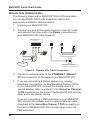
1
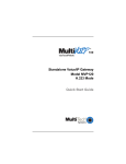
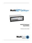
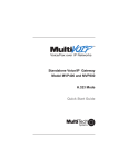
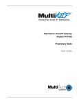
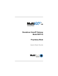
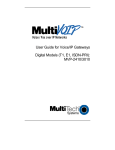
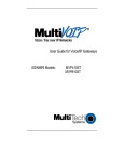
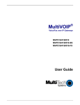
Voice / Fax over IP Networks
Standalone Voice/IP Gateway
Model MVP200
H.323 Mode
Quick Start Guide
Quick Start Guide
S000335A Revision A
MultiVOIP 200 (Model MVP200)
This publication may not be reproduced, in whole or in part, without prior
expressed written permission from Multi-Tech Systems, Inc. All rights
reserved.
Copyright © 2004, by Multi-Tech Systems, Inc.
Multi-Tech Systems, Inc. makes no representations or warranties with
respect to the contents hereof and specifically disclaims any implied
warranties of merchantability or fitness for any particular purpose.
Furthermore, Multi-Tech Systems, Inc. reserves the right to revise this
publication and to make changes from time to time in the content hereof
without obligation of Multi-Tech Systems, Inc. to notify any person or
organization of such revisions or changes.
Record of Revisions
Revision
Description
A
Replacing printed Quick Start 82098177 and changing
(4/12/04) Master/Slave to Client/Host.
Patents
This Product is covered by one or more of the following U.S. Patent
Numbers: 5.682.386; 5.757.801; 6.151.333. Other Patents Pending.
TRADEMARK
Trademark of Multi-Tech Systems, Inc. is the Multi-Tech logo.
Windows and Netmeeting are registered trademarks of Microsoft.
Multi-Tech Systems, Inc.
2205 Woodale Drive
Mounds View, Minnesota 55112
(763) 785-3500 or (800) 328-9717
U.S. Fax 763-785-9874
Technical Support (800) 972-2439
http://www.multitech.com
Contents
Introduction ................................................................................... 4
Related Documentation ................................................................. 5
Installing Your MultiVOIP 200 ........................................................ 6
Installing and Configuring Your MultiVOIP 200 ........................ 6
Deploying the VOIP Network ................................................... 7
Unpacking Your MultiVOIP 200 ...................................................... 8
Safety Warnings ............................................................................ 8
Cabling Your MultiVOIP 200 ........................................................... 9
Cabling Procedure .................................................................. 9
E&M Jumper Block Positioning Procedure .................................. 11
Installing Your MultiVOIP 200 Software ....................................... 12
Configuring Your MultiVOIP 200 .................................................. 17
Registering with a Gatekeeper Phone Directory ................... 28
Building a Proprietary Phonebook Directory ......................... 35
Configuring Your Slave MultiVOIP 200s ................................ 47
Deploying the VOIP Network ....................................................... 60
Remote Site Administrator .................................................... 61
Limited Warranty ......................................................................... 64
Technical Support ........................................................................ 65
FCC Declaration .......................................................................... 65
iii
MultiVOIP Quick Start Guide
Introduction
Welcome to Multi-Tech's new stand-alone Voice/IP Gateway,
the MultiVOIP, model MVP200. The MultiVOIP 200 allows
analog voice and fax communication over an IP network. MultiTech’s voice/fax gateway technology allows voice/fax
communication to be transmitted, with no additional expense,
over your existing IP network, which has traditionally been
data-only. To access this free voice and fax communication, all
you have to do is connect the MultiVOIP 200 to your telephone
equipment, and then to your existing Internet connection. Once
configured, the MultiVOIP 200 then allows voice and fax to
travel down the same path as your traditional data
communications.
The MultiVOIP 200 supports the H.323 standards-based
protocol enabling your MultiVOIP 200 to communicate with
other third-party VOIP Gateways or other endpoints that
support the H.323 protocol (e.g., Microsoft NetMeeting® ). The
H.323 standard defines how endpoints make and receive calls,
how endpoints negotiate a common set of audio and data
capabilities, and how information is formatted and sent over
the network. This version of the software also supports
communication with a Multi-Tech MVPGK1 Gatekeeper or an
optional 3rd party H.323 Gatekeeper which, when enabled,
maintains its own phonebook database, pre-registers all users,
controls the bandwidth, and handles all conferencing issues
such as transferring of calls.
Figure 1. MultiVOIP 200
4
Introduction
The MVP200 has two independent voice/fax channels (each
with three voice/fax interfaces), a 10 Mbps Ethernet LAN
interface, and a Command port for configuration.
System management is provided through the Command port
using bundled Windows® software which provides easy-to-use
configuration menus and comprehensive on-line Help.
Related Documentation
The MultiVOIP 200 Quick Start Guide is intended to be used
by qualified systems administrators and network managers.
This Quick Start Guide provides the necessary information for
a qualified person to unpack, cable, load software, and
configure the unit for proper operation.
A detailed MultiVOIP 200 User Guide is included on your
system CD and provides in-depth information on the features
and functionality of Multi-Tech’s MultiVOIP 200.
The CD media is produced using Adobe AcrobatTM for viewing
and printing the user guide. To view or print your copy of a user
guide, load Acrobat ReaderTM onto your system from the CD,
or obtain it as a free download from Adobe’s Web site:
http://www.adobe.com
The MultiVOIP 200 User Guide is also available on MultiTech’s Web site at:
http://www.multitech.com
Viewing and printing a user guide from the Web also requires
that you have the Acrobat Reader loaded on your system. To
select the MultiVOIP 200 User Guide from the Multi-Tech
Systems home page, click Documents, then click MultiVOIP in
the product list drop-down window, then click MultiVOIP
Manuals. All MultiVOIP 200 documents will be displayed at the
bottom of the page and you can choose User Guide (MVP200) to
view or download the .pdf file.
5
MultiVOIP Quick Start Guide
Installing Your MultiVOIP 200
The basic steps of installing your MultiVOIP 200 network
involve unpacking the units, connecting the cables, and
configuring the units using management software (MultiVOIP
200 Configuration). This process results in a fully functional
Voice Over IP network. A brief description is provided below
with detailed instructions provided later.
Installing and Configuring Your MultiVOIP 200
The VOIP administrator must first install the MultiVOIP 200
software and then configure each MultiVOIP 200 for its specific
function. During the configuration process, it’s important to
note that the Phone Directory Database is configured
differently depending on whether or not you have Gatekeeper
support on your VOIP network.
If your VOIP network supports an H.323 Gatekeeper, you
must register all H.323 endpoints with the Gatekeeper. The
procedure for doing this is explained in the section
“Registering with a Gatekeeper Phone Directory.”
If your VOIP network does not have Gatekeeper software or
the Gatekeeper software is not enabled, then you must build a
proprietary phonebook with a “Host” MultiVOIP 200 and
“Client” MultiVOIP 200s. The “Host” unit includes the
assignment of a unique LAN IP address, subnet mask, and
Gateway IP address; as well as the selection of appropriate
channel interface type for each of the Voice/Fax channels.
Once all connections have been made, the VOIP administrator
configures the unit and builds the Phone Directory Database
that will reside in the Host unit.
After the “Host” MultiVOIP 200 is configured, the administrator
moves on to configure the MultiVOIP 200(s) designated as
“Client” units. Again, unique LAN IP addresses, subnet masks,
and Gateway IP addresses are assigned, and each Voice/Fax
channel is configured for the appropriate channel interface
type. When this is done, the Phone Directory Database option
6
Introduction
is set to Client, and the IP address of the Host MultiVOIP 200
is entered. Once all Client units are configured, the process
moves on to the “Deploying the VOIP Network” section.
Deploying the VOIP Network
The final phase of the installation is deployment of the network.
When the remote MultiVOIP 200s are sent to their remote
sites, the remote site administrators need only connect the
units to their LAN and telephone equipment. A full Phone
Directory Database (supplied by the Host MultiVOIP 200
Proprietary Phonebook will be loaded into their units within
minutes of being connected and powered up.
For remote VOIPs that were configured with the Gatekeeper
option enabled, each MultiVOIP 200 will be registered with the
Gatekeeper (i.e., the Gatekeeper phonebook directory is NOT
downloaded to the remote units).
7
MultiVOIP Quick Start Guide
Unpacking Your MultiVOIP 200
www.multitech.com
Remove all items from the box. (See Figure 2.)
200
Voice/Fax over IP Networks
MADE
IN U.S
.A
U.S.A
MADE IN
Figure 2. Unpacking
Safety Warnings
Caution: Danger of explosion if battery is incorrectly replaced.
A lithium battery on the circuit board provides backup power
for the time keeping capability. The battery has an estimated
life expectancy of ten years.
When the battery starts to weaken, the date and time may be
incorrect. If the battery fails, the board must be sent back to
Multi-Tech Systems for battery replacement.
The E&M, FXS, and Ethernet ports are not designed to be
connected to a Public Telecommunication Network.
8
Cabling
Cabling Your MultiVOIP 200
Cabling your MultiVOIP 200 involves making the proper Power,
Command Port, and Internet connections. Figure 6 shows the
back panel connectors and the associated cable connections.
The Cabling Procedure section provides step-by-step
instructions for cabling your MultiVOIP 200.
Note: Before cabling your MultiVOIP 200, perform the E&M
Jumper Block Positioning Procedure if either voice/fax channel
(1 or 2) will be connected to an E&M trunk that is a Type 1,3, 4,
or 5 rather than a Type 2 (the default).
Cabling Procedure
1. Using the supplied cable, connect the power supply to a
live AC outlet, then plug the power supply into the
MultiVOIP 200 as shown in Figure 3. The power connector
is a 6-pin circular DIN connector.
Voice/Fax Channel 1
E&M
FXS
FXO
Voice/Fax Channel 2
FXO
FXS
E&M
Ethernet RS232
10Base-T Command
1
Power
0
Power Connection
Voice/Fax Channel
1 & 2 Connections
E&M
FXS
FXO
Command Port Connection
PBX
PSTN
Network Connection
Hub
Figure 3. Cable Connections
2. Connect the MultiVOIP 200 to a PC using the RJ-45 to
DB9 (female) cable provided with your unit. Plug the RJ-45
end of the cable into the Command port of the MultiVOIP
200 and connect the other end to the PC’s serial port
(Figure 3).
9
MultiVOIP Quick Start Guide
3. Connect a network cable to the Ethernet 10Base-T
connector on the back of the MultiVOIP 200. Connect the
other end of the cable to your network.
4. If you are connecting a station device; e.g., analog
telephone, fax machine, or Key Telephone System (KTS)
to your MultiVOIP 200, connect the smaller end of a
special adapter cable (supplied) to the Voice/Fax Channel
1 FXS connector on the back of the MultiVOIP 200 and the
other end to the station device.
If you are connecting a PBX extension to your MultiVOIP
200, connect the smaller end of a special adapter cable
(supplied) to the Voice/Fax Channel 1 FXO connector on
the back of the MultiVOIP 200 and the other end to the
PBX extension.
If you are connecting an E&M trunk from a telephone
switch to your MultiVOIP 200, connect one end of an RJ45 cable (not supplied) to the Voice/Fax Channel 1 E&M
connector on the back of the MultiVOIP 200 and the other
end (8 spade lugs or 8 wires to connect directly to the
punch-down block) to the PBX trunk card.
Note: For customers building their own E&M connector,
App. B of the User Guide has a pinout diagram showing
the E&M back panel connector on the MultiVOIP 200.
5. Repeat step 4 to connect the remaining phone equipment
to each Voice/Fax Channel on your MultiVOIP 200.
6. Turn on power to the MultiVOIP 200 by setting the power
switch on the back panel to the 1 (up, On) position. Wait for
the Boot LED on the MultiVOIP 200 to go Off before
proceeding. This may take a couple of minutes.
If you need to change the E&M Jumper Block positioning,
refer to the following section; otherwise, proceed to the
Software Loading section to load MultiVOIP 200 software.
10
Cabling
E&M Jumper Block Positioning Procedure
Each voice/fax channel on the MultiVOIP 200 has a separate
E&M jumper block located near the jacks on the back panel of
the MultiVOIP 200. Each jumper block has 8 pairs of pins with
a jumper plug on three adjacent pairs of pins. The jumper plug
must be centered on the E&M type number (see Figure 4) that
matches the E&M connection for that channel. Perform the
following procedure if you need to move the E&M jumper block
from its default (Type 2) position.
1. Ensure that the external power supply is disconnected
from the MultiVOIP 200.
2. Turn the MultiVOIP 200 upside down and remove the
cabinet mounting screw at the center back of the cabinet.
3. Return the MultiVOIP 200 to its upright position, then slide
the base out the rear of the cabinet.
Note: To change a jumper position, lift the jumper plug up
off the jumper block, then move it to the new position,
ensuring that the middle jumper of the jumper block is
centered on the E&M type number (1,3,4,or 5) as shown
on Figure 4. (Note: Numbers are not on the board.)
Back Panel Connectors
2
Channel 2
2
Channel 1
Jumper Blocks
In Position 2
(Default)
1,3
4
Alternate Positions
Note: Markings do not appear on board.
5
Figure 4. E&M Jumper Block Positions
11
MultiVOIP Quick Start Guide
4. Change the jumper block position for any voice/fax
channel to be connected to an E&M trunk that is not a
Type 2 (the default position).
5. Slide the base all the way into the cabinet until it stops.
6. Turn the MultiVOIP 200 upside down and replace the
cabinet mounting screw that was removed in step 2.
7. If you are using a Magix 400 E&M Tie Card, connect the
ground pin to the chassis ground screw as shown.
MVP 200
Connection
PIN NO.
PIN NO.
M INPUT
1
6
M MOUTH CONTROL
E OUTPUT
2
3
E
4-WIRE OUTPUT
3
1
T1 TIP 1 RECEIVE
R
4 - W I R E I N P U T, 2 - W I R E
4
4
R
RING TRANSMIT
T
4 - W I R E I N P U T, 2 - W I R E
5
5
T
TIP TRANSMIT
4-WIRE OUTPUT
6
2
R1 RING 1 RECEIVE
SG
(SIGNAL GND) OUTPUT
7
CHASSIS GROUND SCREW
( S I G N A L B AT T E RY O U T P U T
8
UNUSED
T1
R1
SB
Magix 400 E&M 4
Wire Tire Card
Male
EAR CONTROL
Male
8. Return the MultiVOIP 200 to its upright position, then
perform the cabling procedure.
12
Installing the Software
Installing Your MultiVOIP 200 Software
The following installation procedures do not provide every
screen or option in the process of installing the MultiVOIP 200
software. It is assumed that a technical person with a thorough
knowledge of Windows and the software loading process is
doing the installation. Once you have installed the software,
you will be instructed on how to configure your MultiVOIP 200,
and finally, on how to deploy your MultiVOIP 200. Additional
information on the MultiVOIP 200 software is provided in the
on-line Help.
Note: The phonebook directory configuration process is
different depending on whether or not you have an enabled
H.323 Gatekeeper resident in your network. The section on
“Configuring Your MultiVOIP 200” will explain these differences.
CAUTION: If you are installing a MultiVOIP 200 behind a
Firewall, the Firewall must support H.323. Refer to your
Firewall user documentation to enable H.323 support.
1. Make certain that your MultiVOIP 200 has been properly
cabled and that it is powered on.
2. Insert the MultiVOIP 200 CD into a CD-ROM drive. The
CD is auto-detectable, so it starts automatically. It may
take 10 to 20 seconds for the Multi-Tech Installation CD
screen to appear.
13
MultiVOIP Quick Start Guide
If the Multi-Tech Installation CD Screen does not appear
automatically, click My Computer, then right-click the CDROM drive icon, click Open, then click the Autorun icon.
3. When the Multi-Tech Installation CD Screen is displayed,
click the Install Software icon.
4. The MultiVOIP 200 Setup welcome screen is displayed.
Press Enter or click Next> to continue.
14
Installing the Software
5. The Choose Destination Location dialog box is
displayed. Follow the on-screen instructions.
You can either choose the Destination Location of your
MultiVOIP 200 software or select the default destination by
clicking Next>. If you click Browse, you can select a
different destination folder for the MultiVOIP 200 software.
6. The Select Program Folder dialog box enables you to
choose where you want the program file to be located.
Verify the path and click Next > to continue.
15
MultiVOIP Quick Start Guide
7. The Copying program files ... screen is displayed
followed by the MultiVOIP 200 Setup dialog box. This
dialog box enables you to select the COM port of your PC
that is connected to the Command port of the MultiVOIP
200. From the Select Port drop-down list, choose the
COM port of your PC.
Click OK to continue.
8. The Setup Complete dialog is displayed.
Click Finish to continue.
16
Installing the Software
9. The following message is displayed:
Click Yes to continue.
10. The following message is displayed.
Click Yes to continue.
17
MultiVOIP Quick Start Guide
Configuring Your MultiVOIP 200
The following steps provide instructions for configuring your
MultiVOIP 200. The configuration sequence includes IP
Protocol default setup, Channel setup, and Phone Directory
Database setup. The Phone Directory Database setup is
configured differently depending on whether or not the
Gatekeeper function is available and enabled on the Phone
Directory Database dialog box.
11. The IP Protocol Default Setup dialog box is displayed.
The default Frame Type is TYPE_II. If this does not match
your IP network, change the Frame Type by clicking the
drop-down arrow and selecting SNAP. The available Frame
Type choices are TYPE_II and SNAP.
12. In the Ethernet group, enter the IP Address, Subnet
Mask, and Gateway Address unique to your IP LAN in
the corresponding fields.
The IP address is the unique LAN IP address that is
assigned to the MultiVOIP 200, and the Gateway address
is the IP address of the device connecting your MultiVOIP
200 to the Internet.
Click OK when you are finished.
13. The Channel Setup dialog box is displayed. The four tabs
in this dialog box define the channel interface, voice/fax
parameters, billing/miscellaneous parameters, and
regional telephone parameters for each channel.
18
Configuring the MultiVOIP
Configure each channel for the type of interface you are
connecting to. The Interface tab defaults to Channel 1 in
the Select Channel field. To change the channel number,
click the drop-down arrow and the list of channels is
displayed. Highlight the channel you want to configure.
Note: Feature options are enabled or disabled (grayed out)
according to the interface type that you select. The one
option available for all interface types is the Inter Digit
Time option. This option defines the maximum amount of
time that the unit will wait before mapping the dialed digits
to an entry in the Phone Directory Database. If too much
time elapses between digits, and the wrong numbers are
mapped, you will hear a rapid busy signal. If this happens,
it will be necessary to hang up and dial again. The default
setting is 2 seconds.
14. The Interface group defaults to FXS (Loop Start). Select
the interface option that corresponds to the interface type
being connected to the Voice/Fax Channel 1 jack on the
back panel of the MultiVOIP 200.
19
MultiVOIP Quick Start Guide
FXS (Loop Start): If a station device; e.g., an analog
telephone, fax machine, or KTS (Key Telephone System) is
connected to the Voice/Fax connector on the back of the
unit, FXS (Loop Start) will likely be the correct Interface.
FXS (Ground Start): If the station device uses ground
start, then choose the FXS (Ground Start) option. Refer to
the device’s user documentation.
For both FXS Loop Start and FXS Ground Start , the Ring
Count FXS window allows you to set the maximum
number of rings output on the FXS interface before
hanging up and releasing the line to another call. The
default setting is 8 rings.
Note: Zero (0) means no rings - caller hears a busy tone.
FXO: If you are using an analog extension from your PBX,
then choose the FXO option. Check with your in-house
phone personnel to verify the connection type.
If FXO is selected, the Dialing Options Regeneration,
Flash Hook Timer, and Ring Count groups are enabled.
Check with your local in-house phone personnel to verify
whether your local PBX dial signaling is Pulse or tone
(DTMF). Then, set the Regeneration option accordingly.
The Flash Hook Timer allows you to enter the time, in
milliseconds, for the duration of the flash hook signals
output on the FXO interface. The default setting is 600
milliseconds. The Ring Count FXO window allows you to
set the number of rings received on the FXO interface
before the MultiVOIP 200 answers the incoming call. The
default setting is 2 rings.
Note: Zero (0) means that the MultiVOIP 200 never
answers.
20
Configuring the MultiVOIP
For FXO-to-FXO communications, you can enable a
specific type of FXO Disconnect; Current Loss, Tone
Detection, or Silence Detection. (Check with your inhouse phone personnel to verify the preferred type of
disconnect to use.) Enabling Tone Detection activates the
Disconnect Tone Sequence options. For Disconnect Tone
Sequence, you can select from drop-down lists either one
or two tones that will cause the line to be disconnected;
the person hanging up a call must then hit the key(s) that
will produce those tones. For Silence Detection, select
One Way or Two Way, then set the timer for the number of
seconds of silence before disconnect. Note that the default
value of 15 seconds may be shorter than desired for your
application.
E&M: If you are connecting to an analog E&M trunk on
your PBX, then choose the E&M interface option to enable
the E&M Options group. Check with your local in-house
phone personnel to determine if the signaling is Dial Tone
or Wink and if the connection is 2-wire or 4-wire. If Wink
signaling is used, then the Wink Timer is enabled with a
default of 250 milliseconds. The range of the Wink Timer is
from 100 to 350 milliseconds. Consult with your local inhouse phone personnel for this timer setting.
Note: After configuring a given channel (1 or 2), you can
copy that channel’s configuration by clicking the Copy
button and everything on the Interface tab will be copied
to the other channel.
15. Repeat the above step to configure the interface type for
voice/fax channel 2.
21
MultiVOIP Quick Start Guide
16. The Voice/Fax tab displays the parameters for the voice
gain, DTMF (Dual Tone Multi-Frequency) gain, voice
coder, faxing, and advanced features such as Silence
Compression, Echo Cancellation, and Forward Error
Correction.
17. You can set up the input and output voice gain so that the
volume can be increased or decreased. Input gain
modifies the level of the audio coming in to the voice
channel before it is sent over the Internet to the remote
MultiVOIP 200; and, output gain modifies the level of the
audio being output to the device attached to the voice
channel. Make your selections from the Input and Output
drop-down lists in the Voice Gain group. The valid range
is +31dB to –31dB with a recommended/default value of 0.
You can also set up the DTMF gain (or output level in
decibels - dB) for the higher and lower frequency groups of
the DTMF tone pair. Make your selections in the dropdown lists in the DTMF Gain group. When DTMF Out of
Band is checked, the unit reproduces the DTMF tones
instead of passing them through.
22
Configuring the MultiVOIP
Note: Only change the DTMF gain under the direction of
Multi-Tech Technical Support supervision.
18. To change the voice coder, first select the channel by
clicking the Select Channel down arrow (highlighting the
channel number) then click Manual in the Coder group. To
select the appropriate coder, click the Selected Coder
down arrow and highlight your new voice coder entry.
If you changed the voice coder, ensure that the same
voice coder is used on the voice/fax channel you are
calling; otherwise, you will always get a busy signal.
Note: If you allow the Coder to be selected automatically,
then you need to select the Max Bandwidth from the
drop-down list. Check with your Network Administrator to
determine how much bandwidth is available.
19. The Fax group enables you to send/receive faxes on the
selected voice/fax channel. You can set the maximum baud
rate for faxes and the fax volume in the two drop-down lists
and change the jitter value in milliseconds.
When receiving fax packets from a remote MultiVOIP 200,
it is possible for individual packets to be delayed or
received out of order due to traffic conditions on the
network. To compensate for this effect, the MultiVOIP 200
uses a Jitter Buffer. The Jitter Value field allows the
MultiVOIP 200 to wait a user-definable period of time, in
milliseconds, for delayed or out of order fax packets. The
range of allowable Jitter Values is 0 to 400 with a default of
400 milliseconds.
If you do not plan to send or receive faxes on a given
voice/fax channel, you can disable faxes in the Fax group.
20. You can enable the voice/fax advanced features by clicking
(checking) the silence compression, echo cancellation, or
forward error correction options.
23
MultiVOIP Quick Start Guide
The Silence Compression option defines whether silence
compression is enabled (checked) for this voice channel. If
silence compression is enabled, the MultiVOIP 200 will not
transmit voice packets when silence is detected, thereby
reducing the amount of network bandwidth that is being
used by the voice channel.
The Echo Cancellation option defines whether echo
cancellation is enabled (checked) for this voice channel. If
echo cancellation is enabled, the MultiVOIP 200 will
remove echo which improves the quality of sound.
The Forward Error Correction (FEC) option defines
whether forward error correction is enabled (checked) for
this voice channel. The FEC feature allows some of the
voice packets that were corrupted (or lost) to be
recovered. FEC adds an additional 50% overhead to the
total network bandwidth consumed by the voice channel.
Note: After configuring a given channel (1 or 2), you can
copy that channel’s configuration by clicking the Copy
button and everything on the Voice/Fax tab will be copied
to the other channel.
24
Configuring the MultiVOIP
21. The Billing/Misc tab displays the parameters for auto call,
automatic disconnection, billing options, and dynamic jitter
buffer.
If you want to dedicate a local voice/fax channel to a
remote voice/fax channel (so you will not have to dial the
remote channel), click the Auto Call Enable option in the
Auto Call group. Then enter the phone number of the
remote MultiVOIP 200 in the Phone Number field.
22. The Automatic Disconnection group provides three
options to be used singly or in combination.
The Jitter Value defines the average inter-arrival packet
deviation (in milliseconds) before the call is automatically
disconnected. Jitter is the inter-arrival packet deviation
(phase shift of digital pulses) over the transmission
medium that causes voice breakup which can be
particularly disruptive to voice communications. The
default setting is 20 milliseconds. A higher value means
that the voice transmission will be more accepting of jitter.
A lower value will be less tolerant of jitter.
25
MultiVOIP Quick Start Guide
Consecutive Packets Lost defines the number of
consecutive packets that are lost after which the call is
automatically disconnected. The default setting is 30.
Call Duration defines the maximum length of time (in
seconds) that a call remains connected before the call is
automatically disconnected. The default setting is 180
seconds. A call limit of three minutes may be too short for
most configurations. Therefore, you may want to increase
this default value.
23. You can set billing options for inbound and/or outbound
calls by checking them in the Billing Options group and
then entering the charge in cents per number of seconds.
24. A minimum and maximum set of values can be set for
Dynamic Jitter Buffer. When receiving voice packets from
a remote MultiVOIP 200, it is possible to experience
varying delays between packets due to traffic conditions
on the network. This is called Jitter. To compensate for this
effect, the MultiVOIP 200 uses a Dynamic Jitter Buffer. The
Jitter Buffer allows the MultiVOIP 200 to wait for delayed
voice packets by automatically adjusting the length of the
Jitter Buffer between configurable minimum and maximum
values. An Optimization Factor adjustment controls how
quickly the length of the Jitter Buffer is increased when
jitter increases on the network. The length of the jitter
buffer directly effects the voice delay between MultiVOIP
200 gateways.
The Minimum Jitter Value default setting is 150
milliseconds, the Maximum Jitter Value default setting is
300 milliseconds, and the Optimization Factor default
setting is 7.
Note: After configuring a given channel (1 or 2), you can
copy that channel’s configuration to the other channel by
clicking the Copy button. Everything on the Billing/Misc
tab will be copied to the other channel.
26
Configuring the MultiVOIP
If your country/region is not the default USA, click the
Regional tab and proceed to step 25; otherwise, proceed
to step 26 to begin building your phone directory database.
25. To change the Tone Pairs on the Regional tab, click the
Country/Region down arrow and highlight your specific
country or region.
Note: If your country or region is not listed, click the
Custom button to define it.
The Tone Pairs group enables you to select/modify the
parameters according to choice. Click OK when finished.
Proceed to step 26 to begin building your phone directory
database.
27
MultiVOIP Quick Start Guide
26. The Phone Directory Database dialog box is displayed
with the Proprietary PhoneBook option enabled and no
phone numbers entries displayed in the database. This
dialog box enables you to select either the GateKeeper or
Proprietary PhoneBook. Once you have choosen the type
of Phone Book database, you can proceed to registering
with a Gatekeeper in the following section (entitled,
Registering with a Gatekeeper Phone Directory); or, if
you are building a proprietary phone book, proceed to
Building a Proprietary Phonebook Directory.
(Note: Each of these sections starts with a step “27.”)
28
Configuring the MultiVOIP
Registering with a Gatekeeper Phone Directory
This section describes how to register H.323 endpoints
with the Gatekeeper. The H.323 Gatekeeper function
resides at a PC acting as the central point for all calls
within its zone and providing call control services to
registered endpoints. The Gatekeeper performs two
important call control functions: address translation from
LAN aliases to IP addresses, and bandwidth management
where the network manager has specified a threshold for
the number of simultaneous conferences on the LAN.
In a GateKeeper environment, you will be enabling the
GateKeeper option, entering an IP address for the
GateKeeper, accepting the default port number, and if the
GateKeeper network is servicing Fast Start, accept the
defaults in the Q.931 Parameters group. However, if this
network zone is primarily non-fast start supported, you will
disable Use Fast Start.
27. Enable the Gatekeeper option
29
MultiVOIP Quick Start Guide
28. If the GateKeeper network employs Fast Start, then accept
the Use Fast Start option (default). You may have to verify
this with the GateKeeper administrator.
29. Enter the Gatekeeper IP Address in the IP Address field
of the RAS Parameters group.
30. Accept the default Port Number 1719.
CAUTION: The default setting for the Gatekeeper Port
Number is 1719. This can be changed to a different value
by the Gatekeeper administrator. If you decide to change
the default Port Number, you must use the same number
on the Gatekeeper and all other H.323 endpoints.
31. When you are finished with this dialog box, click the Add
(+) button to begin building your phone directory database.
The Add/Edit Phone Entry dialog box is displayed.
32. Enter the unique phone number of the local device in the
Phone Number field (e.g., 101).
33. Skip the Description field; i.e., leave it blank.
34. Enter the Voice Channel number corresponding to the
phone number entered.
30
Configuring the MultiVOIP
35. Fill in the H.323 ID field with a description to identify the
phone number. For this example, you could enter “New
York Office 1.”
36. Enter the IP Address of the MultiVOIP you are currently
configuring in the IP Address field.
37. Click OK when you are finished and the Phone Directory
Database dialog box is displayed with your first entry in
the window.
31
MultiVOIP Quick Start Guide
38. Click the Add (+) to enter your next phone listing and the
Add/Edit Phone Entry dialog box is displayed.
39. Enter the second unique phone number of the local device
in the Phone Number field (e.g., 102).
40. Again, skip the Description field (leave it blank).
41. Enter the Voice Channel number corresponding to the
phone number entered. (Hint: for voice channel 2, use your
mouse to select the 1, then change it to a 2.)
42. Fill in the H.323 ID field with a description to identify the
phone number. For this example, you could enter“Jerry’s
Desk.”
43. Enter the IP Address of the MultiVOIP you are currently
configuring in the IP Address field.
32
Configuring the MultiVOIP
44. Click the OK button when you are finished and the Phone
Directory Database dialog box is displayed with your
second entry in the window.
45. Click OK to download the new phone directory database
to the unit.
46. The following dialog box is displayed.
Click OK to download default setup.
33
MultiVOIP Quick Start Guide
47. Once the setup program receives a response from the
MultiVOIP 200, the Writing Setup dialog box is displayed
indicating that the setup configuration is being written to
the MultiVOIP 200.
48. After the setup has been written to the MultiVOIP 200, the
unit is rebooted.
49. Check to ensure that the BOOT LED on the MultiVOIP 200
is Off after the download is complete. This may take
several minutes as the MultiVOIP 200 reboots.
34
Configuring the MultiVOIP
50. You are returned to the Multi-Tech Installation CD screen
from which you can load the Acrobat Reader to your PC.
This allows you to view and/or print the User Guide by
clicking on the Install Manuals icon.
At this time your MultiVOIP 200 is configured. Proceed to
“Deploying the VOIP Network” section.
35
MultiVOIP Quick Start Guide
Building a Proprietary Phonebook Directory
27. To build your proprietary MultiVOIP 200 Phone Directory
(i.e., in an H.323 environment without the Gatekeeper
option enabled), you will first need to enable (check) the
Proprietary Phonebook option and then configure the
“Host” MultiVOIP 200 and then add the “Client” MultiVOIP
200s (or other H.323 endpoints). Configuring the “Client”
MultiVOIP 200 is discussed later.
The first MultiVOIP 200 to be configured is designated the
“Host” and contains the proprietary phonebook database.
All subsequent MultiVOIP 200s added to the proprietary
phonebook database are designated “Clients.” The Host
database contains the phone numbers of all H.323
endpoints available for communication on an IP network.
This database is downloaded to each Client MultiVOIP 200
as it comes on-line.
28. To configure the “Host” MultiVOIP 200, make certain that
the Proprietary Phonebook and Host options are
enabled. The Host IP Address, Send Status Report to
Host, and RAS Parameters group will be disabled (grayed
out).
36
Configuring the MultiVOIP
The Client Status button displays the Client VOIP Status
dialog box used for viewing phone number, IP address,
status, and description of Client units (See “Configuring
Your Client MultiVOIP 200s” for details). Note: In the Q.931
Parameters group, Use Fast Start is checked for
compatibility with other H.323 devices that support Fast
Start Capability.
Click Add (+) to begin building your phone directory
database. The Add/Edit Phone Entry dialog box is
displayed.
29. Enter the unique phone number of the local device in the
Phone Number field (e.g., 101) and indicate that the local
device is connected to Channel 1 in the Voice Channel
field.
30. The Description field is optional, but can be useful in
associating the channel to the extension. If you wish, enter
a description of your local phone number. This description
serves to identify the phone number you entered in the
previous step (e.g., normally the “Host” MultiVOIP 200
resides at the entity’s main office; therefore, for this
example you could enter a description such as “New York
Office 1”).
37
MultiVOIP Quick Start Guide
31. The Station Identification group includes a Hunt Group
drop-down list. This list enables you to indicate which Hunt
Group you want the phone number to be associated with;
or, you can select NO HUNT if you don’t want this entry to
participate in hunting.
Note: Hunting is a series of telephone lines organized in
such a way that if the first line is busy the next line is
hunted and so on until a free line is found. For this
example, assign the phone entry to HUNT GROUP #1.
Once you have assigned this entry to a Hunt Group (or NO
HUNT), you must enter the IP Address of the Host
MultiVOIP 200 in the IP Address field (e.g.,
204.022.122.118).
Note: The Port field becomes active as you begin to enter
the IP Address. The entry is the H.323 industry standard
Port value (1720) used to communicate with other H.323
endpoints.
32. Click OK to return to the Phone Directory Database
dialog box. It now includes phone number (101),
destination details (204.022.122.118 Channel 1), and
description (New York Office 1).
38
Configuring the MultiVOIP
33. To configure Channel 2 on the Host MultiVOIP 200, click
Add (+) and the Add/Edit Phone Entry dialog box is
displayed again.
34. Enter the phone number for the MultiVOIP 200 in the
Station Information group Phone Number field (e.g.,
102).
39
MultiVOIP Quick Start Guide
35. Click inside the Description field and enter a description
for the remote MultiVOIP 200 phone number for Channel 2.
For example, “New York Office 2.” Then, enter the voice
channel number in the Voice Channel field.
36. In the Station Identification group, select HUNT GROUP
#1 from the Hunt Group drop-down list, enter the New
York Office 2’s IP Address (204.022.122.118), and accept
the H.323 industry standard Port value (1720) used to
communicate with other H.323 endpoints.
37. Click OK and you are returned to the Phone Directory
Database dialog box which now includes the second
number and related information in the Phone Number list.
You have completed configuration of the “Host” MultiVOIP
200. Both voice channels belong to Hunt Group # 1. If a
call from an H.323 endpoint (a MultiVOIP 200 or a standalone H.323 endpoint) to Phone Number 101 is unable to
be connected, it will automatically connect to the next
available phone number in Hunt Group #1, i.e., Phone
Number 102.
40
Configuring the MultiVOIP
38. At this point it is time to add all other phone numbers
(Client units and stand-alone units) to the Phone Directory
database. To add Channel 1 of the Client MultiVOIP 200,
click Add (+) and the Add/Edit Phone Entry dialog box is
displayed again.
39. Enter the phone number for the “Client” MultiVOIP 200 in
the Phone Number field (e.g., 201).
40. Click inside the Description field and enter a description
for the remote MultiVOIP 200 phone number for Channel
1; for example, “London Office 1.”
41. In the Station Identification group, select HUNT GROUP
#2 from the Hunt Group drop-down list, enter the London
Office 1’s IP Address (202.056.039.100), and accept the
H.323 industry standard Port value (1720) used to
communicate with other H.323 endpoints.
42. Click OK and you are returned to the Phone Directory
Database dialog box which now includes the remote
phone number and related information in the Phone
Number list.
41
MultiVOIP Quick Start Guide
43. To add Channel 2 of the Client MultiVOIP 200, click Add
(+) and the Add/Edit Phone Entry dialog box is displayed
again.
44. Enter the phone number for the remote (Client) MultiVOIP
200 in the Station Information group Phone Number
field (e.g., 202).
45. Click inside the Description field and enter a description
for the remote MultiVOIP 200 phone number for Channel 2.
For example, “London Office 2.”
46. In the Station Identification group, select HUNT GROUP
#2 from the Hunt Group drop-down list, enter the London
Office 2’s IP Address (202.056.039.100), and accept the
H.323 industry standard Port value (1720) used to
communicate with other H.323 endpoints.
Note: Depending on your requirements, you may want
calls that cannot make a connection to London Office 1
(Hunt Group #2) to roll over to the New York office instead.
In this case, you would configure that phone entry to be
listed as a member of HUNT GROUP #1.
42
Configuring the MultiVOIP
47. Click OK and you are returned to the Phone Directory
Database dialog box which now includes the remote
phone number and related information in the Phone
Number list.
48. To configure a stand-alone endpoint (e.g., a PC with
NetMeeting software), click Add (+) and the Add/Edit
Phone Entry dialog box is displayed again.
43
MultiVOIP Quick Start Guide
49. Enter the phone number for the stand-alone endpoint in
the Station Information group Phone Number field (e.g.,
301).
50. Click inside the Description field and enter a description
for the remote MultiVOIP 200 phone number. For example,
“Human Resources Desk.”
Note: Because the H.323 endpoint is not a MultiVOIP 200,
the Phone Directory database ignores the Voice Channel
entry, i.e., it does not matter what value is entered.
51. In the Station Identification group, select NO HUNT from
the Hunt Group drop-down list, enter the Human
Resource Desk’s IP Address (e.g., 202.198.100.04), and
accept the H.323 industry standard Port value (1720) used
to communicate with other H.323 endpoints.
Note: This stand-alone was not configured as part of a
Hunt Group. However, depending on your requirements,
you could configure a stand-alone to be part of a Hunt
Group.
52. Click OK and you are returned to the Phone Directory
Database dialog box which now includes the stand-alone
phone number and related information in the Phone
Number list.
44
Configuring the MultiVOIP
53. When you have finished, click OK to download the setup
configuration to the MultiVOIP 200.
54. The Checking MultiVOIP 200 dialog box is displayed.
45
MultiVOIP Quick Start Guide
55. Once the setup program receives a response from the
MultiVOIP 200, the Writing Setup dialog box is displayed
indicating that the setup configuration is being written to
the MultiVOIP 200.
56. After the setup has been written to the MultiVOIP 200, the
unit is rebooted.
57. Check to ensure that the BOOT LED on the MultiVOIP 200
is Off after the download is complete. This may take
several minutes as the MultiVOIP 200 reboots.
46
Configuring MultiVOIP Slaves
58. You are returned to the Multi-Tech Installation CD screen
from which you can load the Acrobat Reader to your PC.
This allows you to view and/or print the User Guide by
clicking on the Install Manuals icon.
At this time your Host MultiVOIP 200 is configured.
Proceed to the “Configuring Your Client MultiVOIP 200s”
section.
47
MultiVOIP Quick Start Guide
Configuring Your Client MultiVOIP 200s
If the Proprietary Phonebook option on the Phone Directory
Database dialog box was enabled, then you will need to
configure all remote H.323 endpoints as “Client” units. For
example, the MultiVOIP 200 at the company’s subsidiary office
in London would need to be configured as a “Client.”.
CAUTION: If you are installing a MultiVOIP 200 behind a
Firewall, the Firewall must support H.323. Refer to your
Firewall user documentation to enable H.323 support.
1. Disconnect the PC from the Command port of the Host
MultiVOIP 200 and connect it to the Command port on the
Client MultiVOIP 200.
2. From your desktop, click Programs I MultiVOIP 200 I
MultiVOIP 200 Configuration. The Main menu is
displayed.
3. Click IP to display the IP Setup dialog box.
48
Configuring MultiVOIP Slaves
Click (check) the Enable Diffserv box if you have routers
that support Diffserv (sometimes called IP Precedence).
This feature gives priority to voice packets so they are not
delayed because of large data files being downloaded.
The default Frame Type is TYPE_II. If this does not match
your IP network, change the Frame Type by clicking on the
drop-down arrow. The Frame Type choices are TYPE_II
and SNAP.
4. In the Port Address group, enter the IP Address and IP
Mask. In the Gateway Address group, enter the gateway
IP address for the Client unit.
The IP Address is the unique IP address that you assign to
the MultiVOIP 200, and the Gateway Address is the IP
address of the device (e.g., network router) connected to
the Internet/Intranet.
Click OK when you are finished. The Main menu is
displayed.
5. From the Main menu, click Voice Channels to display the
49
MultiVOIP Quick Start Guide
Channel Setup dialog box. The Channel Setup dialog
box is displayed. The four tabs in this dialog box define the
channel interface, voice/fax parameters, Billing/Misc
parameters, and regional telephone parameters for each
channel.
Configure each channel for the type of interface you are
connecting to. The Interface tab defaults to Channel 1 in
the Select Channel field. To change the channel number,
click the drop-down arrow and the list of channels is
displayed. Highlight the channel you want to configure.
Feature options are enabled or disabled (grayed out)
according to the interface type that you select. The one
option available for all interface types is the Inter Digit
Time option. This option defines the maximum amount of
time that the unit will wait before mapping the dialed digits
to an entry in the Phone Directory Database. If too much
time elapses between digits, and the wrong numbers are
mapped, you will hear a rapid busy signal. If this happens,
it will be necessary to hang up and dial again. The default
is 2 seconds.
50
Configuring MultiVOIP Slaves
6. The Interface group defaults to FXS (Loop Start). Select
the interface option that corresponds to the interface type
being connected to the Voice/Fax Channel 1 jack on the
back panel of the MultiVOIP 200.
FXS (Loop Start): If a station device; e.g., an analog
telephone, fax machine, or KTS (Key Telephone System) is
connected to the Voice/Fax connector on the back of the
unit, FXS (Loop Start) will likely be the correct Interface
option.
FXS (Ground Start): If the station device uses ground
start, then choose the FXS (Ground Start) option. Refer to
the device’s user documentation.
For both FXS Loop Start and FXS Ground Start , the Ring
Count FXS window allows you to set the maximum
number of rings output on the FXS interface before
hanging up and releasing the line to another call. The
default setting is 8 counts.
Note: Zero (0) means no rings - caller hears a busy tone.
FXO: If you are using an analog extension from your PBX,
then choose the FXO option. Check with your in-house
phone personnel to verify the connection type.
If FXO is selected, the Dialing Options Regeneration,
Flash Hook Timer, and Ring Count groups are enabled.
Check with your local in-house phone personnel to verify
whether your local PBX dial signaling is Pulse or tone
(DTMF). Then, set the Regeneration option accordingly.
The Flash Hook Timer allows you to enter the time, in
milliseconds, for the duration of the flash hook signals
output on the FXO interface. The default setting is 600
milliseconds. The Ring Count FXO window allows you to
51
MultiVOIP Quick Start Guide
set the number of rings received on the FXO interface
before the MultiVOIP 200 answers the incoming call. The
default setting is 2 counts.
Note: Zero (0) means that the MultiVOIP 200 never
answers.
For FXO-to-FXO communications, you can enable a
specific type of FXO Disconnect; Current Loss, Tone
Detection, or Silence Detection. (Check with your inhouse phone personnel to verify the preferred type of
disconnect to use.) Enabling Tone Detection activates the
Disconnect Tone Sequence options. For Disconnect Tone
Sequence, you can select from drop-down lists either one
or two tones that will cause the line to be disconnected;
the person hanging up a call must then hit the key(s) that
will produce those tones. For Silence Detection, select
One Way or Two Way, then set the timer for the number of
seconds of silence before disconnect. Note that the default
value of 15 seconds may be shorter than desired for your
application.
E&M: If you are connecting to an analog E&M trunk on
your PBX, then choose the E&M interface option to enable
the E&M Options group. Check with your local in-house
phone personnel to determine if the signaling is Dial Tone
or Wink and if the connection is 2-wire or 4-wire. If Wink
signaling is used, then the Wink Timer is enabled with a
default of 250 milliseconds. The range of the Wink Timer is
from 100 to 350 milliseconds. Consult with your local inhouse phone personnel for this timer setting.
Note: After configuring a given channel (1 or 2), you can
copy that channel’s configuration by clicking the Copy
button and everything on the Interface tab will be copied
to the other channel.
52
Configuring MultiVOIP Slaves
7. Repeat the above step to configure the interface type for
voice/fax channel 2.
8. The Voice/Fax tab displays the parameters for the voice
gain, DTMF (Dual Tone Multi-Frequency) gain, voice
coder, faxing, and advanced features such as Silence
Compression, Echo Cancellation, and Forward Error
Correction.
9. You can set up the input and output voice gain so that the
volume can be increased or decreased. Input gain
modifies the level of the audio coming in to the voice
channel before it is sent over the Internet to the remote
MultiVOIP 200; and, output gain modifies the level of the
audio being output to the device attached to the voice
channel. Make your selections from the Input and Output
drop-down lists in the Voice Gain group. The valid range
is +31dB to –31dB with a recommended/default value of 0.
You can also set up the DTMF gain (or output level in
decibels - dB) for the higher and lower frequency groups of
the DTMF tone pair. Make your selections in the drop53
MultiVOIP Quick Start Guide
down lists in the DTMF Gain group.
Note: Only change the DTMF gain under the direction of
Multi-Tech Technical Support supervision.
10. To change the voice coder, first select the channel by
clicking the Select Channel down arrow (highlighting the
channel number) then click Manual in the Coder group. To
select the appropriate coder, click the Selected Coder
down arrow and highlight your new voice coder entry.
If you changed the voice coder, ensure that the same
voice coder is used on the voice/fax channel you are
calling; otherwise, you will always get a busy signal.
Note: If you allow the Coder to be selected automatically,
then you need to select the Max Bandwidth from the
drop-down list. Check with your VOIP administrator to
determine how much bandwidth is available.
11. The Fax group enables you to send/receive faxes on the
selected voice/fax channel. You can set the maximum baud
rate for faxes and the fax volume in the two drop-down lists
and change the jitter value in milliseconds.
When receiving fax packets from a remote MultiVOIP 200,
it is possible for individual packets to be delayed or
received out of order due to traffic conditions on the
network. To compensate for this effect, the MultiVOIP 200
uses a Jitter Buffer. The Jitter Value field allows the
MultiVOIP 200 to wait a user-definable period of time, in
milliseconds, for delayed or out of order fax packets. The
range of allowable Jitter Values is 0 to 400 with a default of
400 milliseconds.
If you do not plan to send or receive faxes on a given
voice/fax channel, you can disable faxes in the Fax group.
54
Configuring MultiVOIP Slaves
12. You can enable the voice/fax advanced features by clicking
(checking) the silence compression, echo cancellation, or
forward error correction options.
The Silence Compression option defines whether silence
compression is enabled (checked) for this voice channel. If
silence compression is enabled, the MultiVOIP 200 will not
transmit voice packets when silence is detected, thereby
reducing the amount of network bandwidth that is being
used by the voice channel.
This Echo Cancellation option defines whether echo
cancellation is enabled (checked) for this voice channel. If
echo cancellation is enabled, the MultiVOIP 200 will
remove echo-delay which improves the quality of sound.
The Forward Error Correction (FEC) option defines
whether forward error correction is enabled (checked) for
this voice channel. The FEC feature allows some of the
voice packets that were corrupted (or lost) to be
recovered. FEC adds an additional 50% overhead to the
total network bandwidth consumed by the voice channel.
Note: After configuring a given channel (1 or 2), you can
copy that channel’s configuration by clicking the Copy
button and everything on the Voice/Fax tab will be copied
to the other channel.
55
MultiVOIP Quick Start Guide
The Billing/Misc tab displays the parameters for auto call,
automatic disconnection, billing options and dynamic jitter
buffer.
13. If you want to dedicate a local voice/fax channel to a
remote voice/fax channel (so you will not have to dial the
remote channel), click the Auto Call Enable option in the
Auto Call group. Then enter the phone number of the
remote MultiVOIP 200 in the Phone Number field.
14. The Automatic Disconnection group provides three
options to be used singly or in combination.
The Jitter Value defines the average inter-arrival packet
deviation (in milliseconds) before the call is automatically
disconnected. Jitter is the inter-arrival packet deviation
(phase shift of digital pulses) over the transmission
medium that causes voice breakup which can be
particularly disruptive to voice communications. The
default setting is 20 milliseconds. A higher value means
that the voice transmission will be more accepting of jitter.
A lower value will be less tolerant of jitter.
56
Configuring MultiVOIP Slaves
Consecutive Packets Lost defines the number of
consecutive packets that are lost after which the call is
automatically disconnected. The default setting is 30
packets.
Call Duration defines the maximum length of time (in
seconds) that a call remains connected before the call is
automatically disconnected. The default setting is 180
seconds. A call limit of three minutes may be too short for
most configurations. Therefore, you may want to increase
this default value.
15. You can set billing options for inbound and/or outbound
calls by checking them in the Billing Options group and
then entering the charge in cents per number of seconds.
16. A minimum and maximum set of values can be set for
Dynamic Jitter Buffer. When receiving voice packets from
a remote MultiVOIP 200, it is possible to experience
varying delays between packets due to traffic conditions
on the network. This is called Jitter. To compensate for this
effect, the MultiVOIP 200 uses a Dynamic Jitter Buffer. The
Jitter Buffer allows the MultiVOIP 200 to wait for delayed
voice packets by automatically adjusting the length of the
Jitter Buffer between configurable minimum and maximum
values. An Optimization Factor adjustment controls how
quickly the length of the Jitter Buffer is increased when
jitter increases on the network. The length of the jitter
buffer directly effects the voice delay between MultiVOIP
200 gateways.
The Minimum Jitter Value default setting is 150
milliseconds, the Maximum Jitter Value default setting is
300 milliseconds, and the Optimization Factor default
setting is 7.
57
MultiVOIP Quick Start Guide
Note: After configuring a given channel (1 or 2), you can
copy that channel’s configuration to the other channel by
clicking the Copy button. Everything on the Billing/Misc
tab will be copied to the other channel.
If your country/region is not the default USA, click the
Regional tab and proceed to step 17; otherwise, proceed
to step 18 to begin building your phone directory database.
17. To change the Tone Pairs on the Regional tab, click the
Country/Region down arrow and highlight your specific
country or region.
Note: If your country or region is not listed, click the
Custom button to define it.
The Tone Pairs group enables you to select/modify the
parameters according to choice. Click OK when finished
and proceed to step 6 to begin building your phone
directory database.
58
Configuring MultiVOIP Slaves
18. From the Main menu, click Phone Book to display the
Phone Directory Database dialog box. Make certain the
Proprietary Phonebook option is enabled and in the
Database Type group, click the Client option. The Host IP
Address field becomes active.
Note: After you have enabled the Client option, the Client
Status button is replaced by the Update button. Once your
Phone Directory database has been established, you can
click this button to refresh the entries in the Phone
Directory Database window.
19. Enter the IP address (204.022.122.118) of the New York
Office MultiVOIP 200 in the Host IP Address field and
enable the Send Status Report to Host so that status
reports are sent to the Host MultiVOIP 200.
Note: In a Dial-On-Demand (DOD) network, you should
leave Send Status Report to Host disabled (not
checked). This allows the router to disconnect whenever
there is no voice activity. Note that Clients with Send
Status Report to Host disabled will show up as
“Unknown” when viewing Client status on the Host.
59
MultiVOIP Quick Start Guide
20. Click OK to return to the Main menu.
21. Click Download Setup to write the new configuration to
the Client unit. The Save Setup dialog box is displayed.
22. Select (check) the Save Current Setup as User Default
Configuration and click OK. The Writing Setup dialog box
is displayed as the setup configuration is written to the
MultiVOIP 200.
After the setup is written to the MultiVOIP 200, it reboots.
23. Check that the Boot LED on the MultiVOIP 200 is off after
the download is complete. This may take several minutes
as the MultiVOIP 200 reboots.
24. You are returned to the Main menu.
Your MultiVOIP 200 is operational at this time.
Repeat the process for each of the Client units. When all
Clients have been configured, go to “Deploying the Network.”
60
Deploying the VOIP Network
Deploying the VOIP Network
For a Proprietary Phone Directory database, the VOIP
administrator can deploy the pre-configured Client MultiVOIP
200s to their remote sites. The remote site administrators need
only connect power to the pre-configured MultiVOIP 200,
connect the MultiVOIP 200 to their Ethernet LAN and
predefined telephone equipment, and then wait for the phone
directory database to be downloaded.
With the Gatekeeper option enabled on the Phone Directory
Database dialog box, all MultiVOIP 200s are configured as
“Host” and cannot be downloaded. In this case, each
MultiVOIP 200 Phone Book will be programmed with phone
numbers for its own channels. These phone numbers are
registered with the H.323 Gatekeeper (See the “Registering
with a Gatekeeper Phone Directory” section discussed earlier.)
61
MultiVOIP Quick Start Guide
Remote Site Administrator
The following steps are for MultiVOIP 200 H.323 endpoints.
For non-MultiVOIP 200 H.323 endpoints, refer to the
appropriate installation documentation.
1. Unpack your MultiVOIP 200.
2. Connect one end of the power supply to a live AC outlet
and connect the other end to the Power connection on
your MultiVOIP 200 (See Figure 5).
Voice/Fax Channel
Connections
10BASET
E&M FXO FXS
E&M
ETHERNET
POWER
FXS
FXO
Power Connection
PSTN
Ethernet Connection
Figure 5. Remote Site Cable Connection
3. Connect a network cable to the ETHERNET 10Base-T
(RJ-45) connector on the back of your MultiVOIP 200.
4. If you are connecting a station device (e.g., analog
telephone, fax machine, or Key Telephone System (KTS)
to your MultiVOIP 200, connect the smaller end of a
special adapter cable (supplied) to the Voice/Fax Channel
1 FXS connector on the back of the MultiVOIP 200 and the
other end to the station device.
If you are connecting a PBX extension to your MultiVOIP
200, connect the smaller end of a special adapter cable
(supplied) to the Voice/Fax Channel 1 FXO connector on
the back of the MultiVOIP 200 and the other end to the
PBX extension.
62
Deploying the VOIP Network
If you are connecting an E&M trunk from a telephone
switch to your MultiVOIP 200, connect one end of an RJ45 phone cord to the Voice/Fax Channel 1 E&M
connector on the back of the unit and the other end to the
trunk phone jack.
If you are connecting to an E&M trunk, you need to ensure
that the E&M trunk jumper is in the correct position for the
E&M type trunk. The default E&M jumper position is E&M
type 2. To change the E&M jumper position, perform the
E&M jumper block positioning procedure.
5. Repeat the above step to connect the remaining telephone
equipment to each Voice/Fax Channel on your MultiVOIP.
6. Turn on power to the MultiVOIP 200 by placing the ON/
OFF switch on the back panel to the ON position. Wait for
the BOOT LED on the MultiVOIP 200 to go OFF before
proceeding. This may take a couple of minutes.
7. At this time your VOIP network should be fully operational.
Dial one of the sites in your network.
63
MultiVOIP Quick Start Guide
If your H.323 endpoint is not a MultiVOIP 200 (e.g., a PC with
NetMeeting software), the Systems Administrator for your
VOIP network should do the following.
1. Make certain that the H.323 endpoint (e.g., PC with
NetMeeting, router with voice, etc.) have been properly
connected to the network. Refer to the appropriate end
user documentation.
2. Acquire the relevant IP Addresses and/or H323 IDs (H323
IDs are required if Gatekeeper is enabled) from the other
H.323 endpoints that will participate in H.323 calls.
3. Enter these IP Addresses and H323 IDs (H323 IDs are
required if Gatekeeper is enabled) in your phonebook
directory.
64
Warranty and Regulatory Information
Limited Warranty
Multi-Tech Systems, Inc. (“MTS”) warrants that its products will
be free from defects in material or workmanship for a period of
two years from the date of purchase, or if proof of purchase is
not provided, two years from date of shipment. MTS MAKES
NO OTHER WARRANTY, EXPRESSED OR IMPLIED, AND
ALL IMPLIED WARRANTIES OF MERCHANTABILITY AND
FITNESS FOR A PARTICULAR PURPOSE ARE HEREBY
DISCLAIMED. This warranty does not apply to any products
which have been damaged by lightning storms, water, or
power surges or which have been neglected, altered, abused,
used for a purpose other than the one for which they were
manufactured, repaired by the customer or any party without
MTS’s written authorization, or used in any manner
inconsistent with MTS’s instructions.
MTS’s entire obligation under this warranty shall be limited (at
MTS’s option) to repair or replacement of any products which
prove to be defective within the warranty period, or, at MTS’s
option, issuance of a refund of the purchase price. Defective
products must be returned by Customer to MTS’s factory
transportation prepaid.
MTS WILL NOT BE LIABLE FOR CONSEQUENTIAL
DAMAGES AND UNDER NO CIRCUMSTANCES WILL ITS
LIABILITY EXCEED THE PURCHASE PRICE FOR
DEFECTIVE PRODUCTS.
65
MultiVOIP Quick Start Guide
Technical Support
Multi-Tech Systems has an excellent staff of technical support
personnel available to help you get the most out of your MultiTech product. If you have any questions about the operation of
this unit, or experience difficulty during installation you can
contact Tech Support via the following:
Phone:
(800) 972-2439 (USA and Canada)
(763) 785-3500 (international and local)
Internet:
http://www.multitech.com
Please have your product information available, including
model and serial number.
66
Warranty and Regulatory Information
FCC Declaration
NOTE: This equipment has been tested and found to comply with
the limits for a Class A digital device, pursuant to Part 15 of the
FCC Rules. These limits are designed to provide reasonable
protection against harmful interference when the equipment is
operated in a commercial environment. This equipment generates,
uses and can radiate radio frequency energy, and if not installed
and used in accordance with the instructions, may cause harmful
interference to radio communications. Operation of this equipment
in a residential area is likely to cause harmful interference in which
case the user will be required to correct the interference at his own
expense.
Warning: Changes or modifications to this unit not expressly
approved by the party responsible for compliance could void the
user’s authority to operate the equipment.
67
S000335A