1
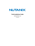
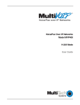
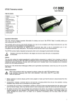
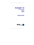
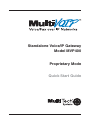
Standalone Voice/IP Gateway
Model MVP400
Proprietary Mode
Quick Start Guide
Quick Start Guide
82099351 Revision B
MultiVOIP (Model MVP400)
This publication may not be reproduced, in whole or in part,
without prior expressed written permission from Multi-Tech
Systems, Inc. All rights reserved.
Copyright © 2002, by Multi-Tech Systems, Inc.
Multi-Tech Systems, Inc. makes no representations or warranties
with respect to the contents hereof and specifically disclaims any
implied warranties of merchantability or fitness for any particular
purpose. Furthermore, Multi-Tech Systems, Inc. reserves the right
to revise this publication and to make changes from time to time in
the content hereof without obligation of Multi-Tech Systems, Inc. to
notify any person or organization of such revisions or changes.
Record of Revisions
Revision
Description
A
(10/07/01)
B
(01/28/02)
Manual released. Covers software version 3.01.
Remove MultiVOIP Manager from splash screen.
Patents
This Product is covered by one or more of the following U.S.
Patent Numbers: 6151333, 5757801, 5682386. Other Patents
Pending.
TRADEMARK
Trademark of Multi-Tech Systems, Inc. is the Multi-Tech logo.
Windows is a registered trademark of Microsoft.
Multi-Tech Systems, Inc.
2205 Woodale Drive
Mounds View, Minnesota 55112
(763) 785-3500 or (800) 328-9717
Fax 763-785-9874
Tech Support (800) 972-2439
Internet Address: http://www.multitech.com
Contents
Introduction ................................................................................... 4
Related Documentation ................................................................. 5
Installing Your MultiVOIP ............................................................... 6
Configure and Install your Host MultiVOIP ............................. 6
Configure your Client MultiVOIPs ........................................... 6
Deploy the VOIP Network ...................................................... 6
Unpacking Your MultiVOIP ............................................................ 8
Safety Warnings ............................................................................ 8
Cabling Your MultiVOIP ................................................................ 9
E&M Jumper Block Positioning Procedure ............................ 11
Configuring Your Host MultiVOIP ................................................ 13
Configuring Your Client MultiVOIPs ............................................. 30
Deploying the VOIP Network ....................................................... 41
Limited Warranty ......................................................................... 44
Technical Support ........................................................................ 45
FCC Declaration .......................................................................... 46
iii
MultiVOIP Quick Start Guide
Introduction
Welcome to Multi-Tech's new standalone Voice/IP Gateway
which allows analog voice and fax communication over an IP
network. The MultiVOIP model number is MVP400 and is a
four-channel unit. Multi-Tech’s new voice/fax over IP gateway
technology allows voice and fax communication to ride, with
no additional expense, over your existing IP network, which
has traditionally been data-only. To access this free voice and
fax communication, all you have to do is connect your
MultiVOIP to your telephone equipment, and then to your
existing Ethernet LAN. Once configured, the MultiVOIP then
allows voice and fax to travel down the same path as your
traditional data communications.
The MVP400 is designed with four voice/fax channels (which
offer three voice/fax interfaces per channel), a 10M bps Ethernet
LAN interface, and a command port for configuration.
System management is provided through the command port
using bundled Windows® software, which provides easy-touse configuration menus and online Help.
Figure 1. MultiVOIP
4
Introduction
Related Documentation
The MultiVOIP Quick Start Guide is intended to be used by a
qualified VOIP Administrator (one that has both telephony and
networking experience). This Quick Start Guide provides the
necessary information for a qualified administrator to unpack,
cable, load software, and configure the host and client units for
proper operation.
A detailed MultiVOIP User Guide is also provided on the
system CD with your unit. This user guide provides in-depth
information on the features and functionality of Multi-Tech’s
MultiVOIP. The User Guide is provided in .pdf format on the
system CD and is also available from our Web site.
The User Guide is produced using Adobe AcrobatTM. To view
or print your copy of a user guide, install Acrobat ReaderTM on
your computer. The Acrobat Reader is included on your
system CD or is available as a free download from Adobe’s
Web site at http://www.adobe.com.
Launch the Reader and select the .pdf file from the CD.
Viewing and printing a user guide from the web also requires
that you have the Adobe Acrobat Reader loaded on your
system. The MultiVOIP User Guide is also available on MultiTech’s Web site at http://www.multitech.com
From the MTS homepage, click Support | Manuals | MultiVOIP
and choose the appropriate User Guide to download the .pdf file.
5
MultiVOIP Quick Start Guide
Installing Your MultiVOIP
The basic steps of installing your MultiVOIP network involve
unpacking the units, connecting the cables, and configuring
the units using the included management software (MultiVOIP
Configuration). The recommended installation process
includes three phases that, when completed, result in a fully
functional Voice Over IP network. A general description of
each phase is provided below, and detailed instructions follow
throughout the rest of this section.
Configure and Install your Host MultiVOIP
As the first step, the VOIP administrator configures the
MultiVOIP designated as the “Host” unit. This includes the
assignment of a unique LAN IP address, subnet mask, and
Gateway IP address, as well as the selection of appropriate
channel interface type for each of the Voice/Fax channels.
Once all connections have been made, the VOIP administrator
configures the unit and builds the Phone Directory Database
that will reside in the Host unit.
Configure your Client MultiVOIPs
The next step is to configure the MultiVOIPs designated as
“Client” units. The Client units can be another MVP400, a
MVP800 unit, MVP200 or a MultiVOIP 100 Series. Again,
unique LAN IP addresses, subnet masks, and Gateway IP
addresses are assigned, and each Voice/Fax channel is
configured for the appropriate channel interface type. When
this is done, the Phone Directory Database option is set to
Client, and the IP address of the Host MultiVOIP is entered.
Once all client units are configured, the process moves on to
Phase 3.
Deploy the VOIP Network
The final phase of installation is deployment of the network.
Through the first two phases, the VOIP administrator controls
configuration, so when the Client MultiVOIPs are sent to their
6
Introduction
remote sites, the remote site administrators need only to
connect the units to their LAN and telephone equipment. A full
Phone Directory Database (supplied by the Host MultiVOIP)
will be loaded into their unit within minutes of being connected
and powered up.
The final task of the VOIP Administrator is to develop the VOIP
Dialing Directory based on the Phone Directory Database and
the phone numbers of the interfacing telephone equipment.
Now, a VOIP User can call any person on the VOIP network.
7
MultiVOIP Quick Start Guide
Unpacking Your MultiVOIP
www.multitech.com
Remove all items from the box.
Voice/Fax over IP Networks
Figure 2. Unpacking
Safety Warnings
Caution
Danger of explosion if battery is incorrectly replaced.
A lithium battery on the voice/fax channel board provides
backup power for the time keeping capability. The battery has
an estimated life expectancy of ten years.
When the battery starts to weaken, the date and time may be
incorrect. If the battery fails, the board must be sent back to
Multi-Tech Sytems for battery replacement.
The E&M, FXS, and Ethernet ports are not designed to be
connected to a Public Telecommunication Network.
8
Cabling
Cabling Your MultiVOIP
Cabling your MultiVOIPinvolves connecting the host MultiVOIP
to your LAN and telephone equipment.
If you are connecting any Voice/Fax Channel to an E&M trunk
other than type 2, perform the E&M Jumper Block Positioning
procedure, which immediately follows the Cabling Procedure,
before performing the Cabling Procedure.
1. Connect one end of the power supply to a live AC outlet
and connect the other end to the MultiVOIP as shown in
Figure 3. The power connector is a 7-pin circular DIN
connector.
VOICE/
FAX
CHANNEL
8
VOICE/
FAX
CHANNEL
7
E&M
FXO
VOICE/
FAX
CHANNEL
4
FXS
VOICE/
FAX
CHANNEL
6
E&M
FXO
FXS
VOICE/
FAX
CHANNEL
3
VOICE/
FAX
CHANNEL
5
E&M
FXO
FXS
VOICE/
FAX
CHANNEL
2
E&M
FXO
INTERNAL
COMPOSITE
LINK
FXS
VOICE/
FAX
CHANNEL
1
MONITOR
XMT
RCV
T1 DSU
GND
CHANNEL 10
CHANNEL 9
CHANNEL 8
CHANNEL 6
CHANNEL 7
CHANNEL 4
CHANNEL 5
CHANNEL 3
CHANNEL 2 (RS232/V.35)
CHANNEL 1 (RS232/V.35)
10BASET
COMMAND PORT
ETHERNET
EXT. COMPOSITE LINK (RS232/V.35)
I
POWER
O
Voice/Fax Channel 1 - 8
Connections
Power Connection
E&M
FXO
E&M
FXS
FXS
FXO
Command Port Connection
PSTN
Ethernet Connection
Figure 3. Cable Connections
2. Connect the MultiVOIP to a PC by using the DB-9 to DB-25
cable provided with your unit. Plug the DB-25 end of the
cable into the Command port of the MultiVOIP and the
other end into the serial port on the PC. See Figure 3.
9
MultiVOIP Quick Start Guide
3. Connect a network cable to the ETHERNET 10BASET
connector on the back of the MultiVOIP. Connect the other
end of the cable to your network.
4. If you are connecting a station device such as an analog
telephone, a fax machine, or a Key Telephone System
(KTS) to your MultiVOIP, connect one end of an RJ11
phone cord to the Voice/Fax Channel 1 FXS connector on
the back of the MultiVOIP and the other end to the station
device.
If you are connecting a PBX extension to your MultiVOIP,
connect one end of an RJ11 phone cord to the Voice/Fax
Channel 1 FXO connector on the back of the MultiVOIP
and the other end to the PBX extension.
If you are connecting an E&M trunk from a telephone
switch to your MultiVOIP, connect one end of an RJ45
phone cord to the Voice/Fax Channel 1 E&M connector
on the back of the MultiVOIP and the other end to the
trunk. Refer to the User Guide for E&M pin assignments.
If you are connecting to an E&M trunk, you need to ensure
that the E&M trunk jumper is in the correct position for the
E&M type trunk. The default E&M jumper position is E&M
type 2. To change the E&M jumper position, perform the
E&M jumper block positioning procedure, which
immediately follows this procedure.
5. Repeat the above step to connect the remaining telephone
equipment to each Voice/Fax Channel on your MultiVOIP.
6. Turn on power to the MultiVOIP by placing the ON/OFF
switch on the back panel to the ON position. Wait for the
BOOT LED on the MultiVOIP to go off before proceeding.
This may take a couple minutes.
Proceed to the next section to load the MultiVOIP software.
10
Cabling
E&M Jumper Block Positioning Procedure
A jumper block exists for each voice/fax channel. The jumper
block is to the right of each set of channel jacks. The jumper
block contains 8-pairs of pins. The jumper plug fits over three
pairs of pins on the jumper block. The E&M type number is
labeled on the pc board. The jumper plug needs to be
centered on the E&M type number. Perform the following
procedure to change E&M jumper position.
1. Ensure that power is removed from the MultiVOIP.
2. Remove the front panel by loosening the two Phillips quarter
turn screws.
3. Remove the eight chassis mounting screws and slide the top
cover back off the chassis to expose the rear panel.
4. To change a jumper position, lift the jumper plug up off the
jumper block and move to the new position, ensuring that the
center jumper is centered on the E&M type number.
2 (Default)
1,3
4
5
5. Change the jumper position for each voice/fax channel
that is connecting to an E&M trunk that is not a type 2. If
you have two voice/fax channel boards in your unit and
you need to change the jumpers on the second board,
remove the six screws from the top board and disconnect
the ribbon cable from the top board.
6. Slide the top cover back on to the chassis and replace the
eight retaining screws removed in step 3.
7. Replace the front panel and secure it by tightening the two
Phillips quarter turn screws.
11
MultiVOIP Quick Start Guide
8. If you are using a Magix 400 E&M Tie Card, connect the
ground pin to the chassis ground screw as shown.
MVP 400
Connection
PIN NO.
M INPUT
1
6
M MOUTH CONTROL
2
3
E
4-WIRE OUTPUT
3
1
T1 TIP 1 RECEIVE
R
4 - W I R E I N P U T, 2 - W I R E
4
4
R
RING TRANSMIT
T
4 - W I R E I N P U T, 2 - W I R E
5
5
T
TIP TRANSMIT
4-WIRE OUTPUT
6
2
R1 RING 1 RECEIVE
SG
(SIGNAL GND) OUTPUT
7
CHASSIS GROUND SCREW
( S I G N A L B AT T E RY O U T P U T
8
UNUSED
R1
Male
9. Return to the Cabling Procedure.
12
PIN NO.
E OUTPUT
T1
SB
Magix 400 E&M 4
Wire Tire Card
Male
EAR CONTROL
Software Installation
Configuring Your Host MultiVOIP
The following software loading procedure does not provide
every screen or option in the loading process. The
assumption is that a technical person with a thorough
knowledge of Windows and the software loading process is
doing the installation. Additional information on the MultiVOIP
software is provided in the User Guide supplied with your
MultiVOIP.
If you are installing a MultiVOIP behind a firewall, you need to
add the following UDP ports to your firewall.
Q.931 Signaling, Ch1[900]
Q.931 Signaling, Ch3[904]
Status [5000]
Ch1 RTP [5004]
Ch2 RTP[5006]
Ch3 RTP[5008]
Ch4 RTP[5010]
Q.931 Signaling, Ch2 [902]
Q.931 Signaling, Ch4 [906]
Ch1 RTCP [5005]
Ch2 RTCP [5007]
Ch3 RTCP [5009]
Ch4 RTCP [5011]
Refer to your firewall user documentation to enter and open
these ports.
1. Verify that your MultiVOIP400 has been properly cabled
and that the power is turned on.
2. Insert the MultiVOIP400 CD into your CD-ROM drive. The
CD should start automatically. It may take 10 to 20
seconds for the MultiTech CD installation window to
display.
13
MultiVOIP Quick Start Guide
If the Multi-Tech Installation CD window does not display
automatically, click My Computer, then right click the CD
ROM drive icon, click Open, and then click the Autorun
icon.
3. When the Multi-Tech Installation CD dialog box displays,
click the Install Software icon.
4. The Select Software dialog box is displayed. Select
Proprietary Software option.
14
Software Installation
5. The Welcome dialog box displays.
Click Next to continue.
6. Follow the on-screen instructions to install your MultiVOIP
software.
You may choose the Destination Location of your
MultiVOIP software or you can choose to select the default
destination by clicking Next.
15
MultiVOIP Quick Start Guide
If you click Browse, you can choose from several folders.
It is recommended to choose the default destination.
7. The following dialog box selects the COM port of your PC
connected to the Command port of the MultiVOIP. Select
the COM port of your PC from the Select Port window.
Click OK to continue.
8. The Setup Complete dialog displays.
Click Finish to continue.
16
Software Installation
9. The following message displays:
Click No to continue.
10. From the MultiVOIP Program Group, double click on
Upgrade Software.
Click Yes to continue.
11. The IP Protocol Default Setup dialog box displays.
The default Frame Type is TYPE_II. If this does not match
your IP network, change the Frame Type by clicking the drop
down box. The Frame Type choices are TYPE_II and SNAP.
12. In the Ethernet group, enter the IP Address, Subnet
Mask, and Gateway Address, unique to your IP LAN.
17
MultiVOIP Quick Start Guide
The IP address is your unique LAN IP address, and the
Gateway address is the IP address of the device
connected to the Internet/Intranet.
Click OK when you are finished.
13. The Channel Setup dialog box displays. The Channel
Setup dialog boxes define the channel interface, voice
coder, fax parameters, and regional telephone parameters
for each channel.
Configure each channel for the type of interface you are
connecting to. Channel 1 displays by default in the Select
Channel list. To change the channel number, select the
channel number you want to configure from the Select
Channel list.
14. The Interface group defaults to FXS (Loop Start). Select
the interface option to correspond to the interface type
being connected to the Voice/Fax connector on the back
panel of the MultiVOIP.
18
Software Installation
If you are connecting a station device such as an analog
telephone, a fax machine, or a Key Telephone System
(KTS) to the Voice/Fax connector on the back of the unit,
FXS (Loop Start) will most likely be the correct Interface
option most of the time .
If the station device uses ground start, then choose the
FXS (Ground Start) option. Refer to the device’s user
documentation.
If you are using an extension from your PBX, then choose
the FXO option. Check with your in-house telephone
personnel to verify connection type.
If you are connecting to an E&M trunk on your PBX, then
choose E&M option.
If the E&M interface is selected, the E&M Options group is
enabled. Check with your in-house phone personnel to
determine if the signaling is Dial Tone or Wink and if the
connection is 2-wire or 4-wire. If Wink signaling is used,
then the Wink Timer is enabled with a default of 250
milliseconds. The range of the Wink Timer is from 100 to
350 milliseconds. Consult with your local in-house phone
personnel for this timer setting. If the Pass Through
check box is selected, a continuously open E&M voice
path is established between two channels to pass voice
packets. Available if the Dial Tone option is selected and
auto-dialing is set up for the two channels that will be
doing pass-through. This is useful for Public Address
systems.
If you choose an FXO or FXS interface, the Dialing
Options Regeneration group is enabled. Check with your
in-house telephone personnel to verify whether your local
PBX dial signaling is Pulse or DTMF (tone). Set the
Regeneration option accordingly. In the Max Dial Digits
box, enter the maximum number of digits allowed when
dialing a phone number. The default setting is 5. In the
Inter Digit Time box, enter the maximum amount of time
19
MultiVOIP Quick Start Guide
in milliseconds that the unit will wait before mapping the
dialed digits to an entry in the Phone Directory Database.
If too much time elapses between digits and the wrong
numbers are mapped, you hear a rapid busy signal. If this
happens, hang up and dial again. This option is available
for all interface types. In the Flash Timer box, enter the
time, in milliseconds, for the duration of flash hook signals
output on the FXO or FXS interface.
To dedicate a local voice/fax channel to a remote voice/fax
channel, (so you will not have to dial the remote channel)
select the Auto Call Enable check box. Enter the phone
number of the remote VOIP in the Phone Number box.
For FXO-to-FXO communications, you can enable a
specific type of FXO Disconnect: current loss, tone
detection, or silence detection. Check with your inhouse phone personnel to verify the preferred type of
disconnect to use. For tone detection, you can select
from the lists either one or two tones that will cause the
line to disconnect. The person hanging up a call must
then hit the key or keys that will produce those tones. For
silence detection, select One Way or Two Way, then set
the timer for the number of seconds of silence before
disconnect. The default value of 15 seconds may be
shorter than desired for your application.
The FXS Options control how the selected channel
interacts with answering machines. If the Current Loss
check box is selected, the local VOIP hangs up when the
electrical current is lost. The remote VOIPs must also be
confirgured for current loss. The Ring Count box
contains the number of rings before the caller hears a fast
Busy signal. If this happens, hang up and try again. The
default setting is 8 rings.
Note: After configuring a given channel, you can copy that
channel’s configuration to any other channel by clicking
Copy. Everything on the Interface tab will be copied to
the other channel.
20
Software Installation
15. Repeat the above steps to configure the interface type for
each voice/fax channel.
The Voice/Fax tab displays the parameters for the voice
coder, faxing, and DTMF gain.
16. To change the voice coder, select the channel from the
Select Channel list, then select the new voice coder entry
from the Voice Coder list.
If you changed the voice coder, ensure that the same
voice coder is used on the voice/fax channel you are
calling. Otherwise, you will always get a busy signal.
17. If you selected the FXO interface and are using touchtone
dialing, you can set up the DTMF gain (or output level in
decibels - dB) for the higher and lower frequency groups
of the DTMF tone pair. Make your selections from the
lists in the DTMF Gain group. In the Duration box, enter
the DTMF tone duration in milliseconds. 100 is entered by
default.
21
MultiVOIP Quick Start Guide
Note: Only change the DTMF gain under the direction of
Multi-Tech Technical Support.
18. The Fax group enables you to send and receive faxes on
the selected voice/fax channel. You can select the
maximum baud rate for faxes from the list in the Fax
group. If you do not plan to send or receive faxes on a
given voice/fax channel, you can disable faxes in the Fax
group.
Note: After configuring a given channel, you can copy that
channel’s configuration to any other channel by clicking
Copy. Everything on the Voice/Fax tab will be copied to
the other channel.
19. The Billing/Security tab displays the parameters for
automatic disconnection, billing options, and dialing
options.
20. You can set up billing options for inbound and outbound
calls by selecting them in the Billing Options group and
then entering the charge in cents per number of seconds.
22
Software Installation
21. The Call Authentication option enables password
protection for outbound and inbound calls on the selected
voice/fax channel. If you enable password protection on
inbound or outbound calls, you need to also enter a
password of up to 14 numeric characters in the Password
box.
22. The Automatic Disconnect option limits call duration to
the number of seconds entered in the Disconnect After
box. The default value of 180 seconds can be changed to
any other value up to 65,535 (roughly 18.2 hours).
If your country/region is not the default USA, click the
Regional tab and proceed to step 23. Otherwise, proceed
to step 24 to begin building your phone directory database.
23. To change the Tone Pairs on the Regional tab, select your
specific country or region from the Country/Region list.
The Tone Pairs group parameters change per your
choice. Click OK when finished.
23
MultiVOIP Quick Start Guide
24. The following dialog box is displayed.
Click OK. Each component is loaded in succession.
25. From the Program Group, double-click MultiVOIP
Configuration. Click Phone Book. The Phone Directory
Database dialog box displays. You will build your
personalized MultiVOIP Phone Directory in the following
steps.
The MultiVOIP configured as a “Host” will contain the host
database. The host database has the phone numbers of all
the MultiVOIP’s available for communication on an IP
network. This database is downloaded to each Client
MultiVOIP as it comes online.
24
Software Installation
Click Add to begin building your phone directory database.
26. The Add/Edit Phone Entry dialog displays.
In the Station Information group, enter the unique phone
number of the local device connected to Channel 1 in the
Phone Number box (for example phone number 101).
27. The Description is optional, but can be useful in
associating the channel to the extension. If you want, enter
a description of your local phone number. This description
identifies the phone number you entered in the previous
step.
28. The Permit Hunting option enables the answering unit to
roll over to a second channel if the first channel is busy.
Click Permit Hunting if you want the calls to roll over to a
second local voice/fax channel. (Calls will only roll over
within an individual MultiVOIP; for example, if all of a
MultiVOIPs lines or channels are busy, the next call will
not hunt to another MultiVOIP).
Note: The Host MultiVOIP must have a static IP address
that the remote MultiVOIP can reference to obtain a
downloaded copy of the host phone directory database.
29. In the MultiVOIP Identification group, enter the IP
address of the Host MultiVOIP in the IP Address box. For
25
MultiVOIP Quick Start Guide
example, 204.22.122.118. Then obtain the 12-digit Node
ID# (0008005xxxxx) from the ID plate on the back panel of
the MultiVOIP and enter this number in the Ethernet
Node ID box. If the ID plate is missing or damaged, you
can also Telnet to the MultiVOIP and, on the MultiVOIP
Telnet Server menu enter 1 to advance to the Main Menu,
then enter 3 for System Information where item 1 is the
Ethernet Port Address you want to enter in the Ethernet
Node ID box.
26
Software Installation
30. Click OK and you are returned to the Phone Directory
Database dialog box, which now includes phone number
101 with its IP address, channel number, and description.
31. Click Add and the Add/Edit Phone Entry dialog box
displays again.
32. Enter the phone number for the remote MultiVOIP in the
Station Information group Phone Number box. For
example, 201.
33. Enter a description for the remote MultiVOIP phone
number for Channel 1 in the Description box.
Note: If the remote MultiVOIP is located behind a proxy
server that uses a dynamically assigned IP address, select
Dynamic (disabling Static IP Address) and leave the IP
Address box blank. The Host MultiVOIP will learn the IP
address when it is contacted by the remote MultiVOIP.
34. Enter the IP address of the remote MultiVOIP in the IP
Address box in the MultiVOIP Identification group. For
example, 202.56.39.100.
27
MultiVOIP Quick Start Guide
35. Click OK and you are returned to the Phone Directory
Database dialog box, which now includes the second
number and related information in the Phone Number list.
Note: If only Channel 1 is active, you must enter two
phone numbers. The first number will be the local
28
Software Installation
MultiVOIP phone number for Channel 1, and the second
number will be the remote MultiVOIP phone number for
Channel 1.
36. When you have finished, click OK. You are returned to the
Main menu, now click on Download Setup to write the
new configuration to the MultiVOIP.
37. After the setup is written to the MultiVOIP, the unit is
rebooted.
38. Verify that the BTG LED on the MultiVOIP is off after the
download is complete. This may take several minutes as
the MultiVOIP reboots.
39. You are returned to the Main menu. At this time, your
MulitVOIP is configured. Click Exit. Proceed to the next
section to configure the client MultiVOIPs.
29
MultiVOIP Quick Start Guide
Configuring Your Client MultiVOIPs
The client MultiVOIPs can be another MVP 400, MVP 800,
MVP200, or a MultiVOIP 100-series.
If your client MultiVOIP is an MVP 400, perform the following
software loading procedure.
If your client MultiVOIP is an MVP 800, MVP200, or MVP100
series, connect your command port cable and power up the
unit according to the cabling procedure in the approrpriate
MultiVOIP Quick Start. Then configure the unit as a client per
the Software Installation procedures in that Quick Start.
If you are installing a MultiVOIP behind a firewall, you need to
add the following UDP ports to your firewall.
Q.931 Signaling, Ch1[900]
Q.931 Signaling, Ch2 [902]
Q.931 Signaling, Ch3[904]
Q.931 Signaling, Ch4 [906]
Status [5000]
Ch1 RTP [5004]
Ch1 RTCP [5005]
Ch2 RTP[5006]
Ch2 RTCP [5007]
Ch3 RTP[5008]
Ch3 RTCP [5009]
Ch4 RTP[5010]
Ch4 RTCP [5011]
Refer to your firewall user documentation to enter and open
these ports.
1. Disconnect the pc from the command port of the Host
MultiVOIP and connect it to the command port on the
Client MultiVOIP.
2. From your desktop, click Start | Programs I MultiVOIP
800 v. 301F I Upgrade Software. The following dialog
box displays.
30
Software Installation
Click Yes.
3. The IP Protocol Default Setup dialog box displays.
The default Frame Type is TYPE_II. If this does not match
your IP network, select the Frame Type from the Frame
Type list. The Frame Type choices are TYPE_II and SNAP.
4. In the Ethernet group, enter the IP Address and IP Mask.
In the Gateway Address, enter the gateway IP address
for the client unit.
The IP address is your unique LAN IP address, and the
Gateway address is the IP address of the device
connected to the Internet/Intranet.
Click OK when you are finished.
31
MultiVOIP Quick Start Guide
5. The Channel Setup dialog box displays. The Channel
Setup dialog box defines the channel interface, voice
coder, fax parameters, and regional telephone parameters
for each channel.
Configure each channel for the type of interface you are
connecting to. To change the channel number, select the
channel you want to configure from the Select Channel
list .
6. The Interface group defaults to FXS (Loop Start). Select
the interface option to correspond to the interface type
being connected to the Voice/Fax connector on the back
panel of the MultiVOIP.
If you are connecting a station device such as an analog
telephone, a fax machine, or a Key Telephone System
(KTS) to the Voice/Fax connector on the back of the unit,
FXS (Loop Start) will likely be the correct Interface option
most of the time.
32
Software Installation
If the station device uses ground start, then choose the
FXS (Ground Start) option. Refer to the device’s user
documentation.
If you are using an extension from your PBX, then choose
the FXO option. Check with your in-house telephone
personnel to verify connection type.
If you are connecting to an E&M trunk on your PBX, select
the E&M option.
If the E&M interface is selected, the E&M Options group is
enabled. Check with your in-house phone personnel to
determine if the signaling is Dial Tone or Wink and if the
connection is 2-wire or 4-wire. If Wink signaling is used,
then the Wink Timer is enabled with a default of 250
milliseconds. The range of the Wink Timer is from 100 to
350 milliseconds. Consult with your local in-house phone
personnel for this timer setting. If the Pass Through
check box is selected, a continuously open E&M voice
path is established between two channels to pass voice
packets. Available if the Dial Tone option is selected and
auto-dialing is set up for the two channels that will be
doing pass-through. This is useful for Public Address
systems.
If you choose an FXO or FXS interface, the Dialing
Options Regeneration group is enabled. Check with your
in-house telephone personnel to verify whether your local
PBX dial signaling is Pulse or DTMF (tone). Set the
Regeneration option accordingly. In the Max Dial Digits
box, enter the maximum number of digits allowed when
dialing a phone number. The default setting is 5. In the
Inter Digit Time box, enter the maximum amount of time
in milliseconds that the unit will wait before mapping the
dialed digits to an entry in the Phone Directory Database.
If too much time elapses between digits and the wrong
numbers are mapped, you hear a rapid busy signal. If this
happens, hang up and dial again. This option is available
33
MultiVOIP Quick Start Guide
for all interface types. In the Flash Timer box, enter the
time, in milliseconds, for the duration of flash hook signals
output on the FXO or FXS interface.
To dedicate a local voice/fax channel to a remote voice/fax
channel, (so you will not have to dial the remote channel)
select the Auto Call Enable check box. Enter the phone
number of the remote VOIP in the Phone Number box.
For FXO-to-FXO communications, you can enable a
specific type of FXO Disconnect: current loss, tone
detection, or silence detection. Check with your inhouse phone personnel to verify the preferred type of
disconnect to use. For tone detection, you can select
from the lists either one or two tones that will cause the
line to disconnect. The person hanging up a call must
then hit the key or keys that will produce those tones. For
silence detection, select One Way or Two Way, then set
the timer for the number of seconds of silence before
disconnect. The default value of 15 seconds may be
shorter than desired for your application.
The FXS Options control how the selected channel
interacts with answering machines. If the Current Loss
check box is selected, the local VOIP hangs up when the
electrical current is lost. The remote VOIPs must also be
confirgured for current loss. The Ring Count box
contains the number of rings before the caller hears a fast
Busy signal. If this happens, hang up and try again. The
default setting is 8 rings.
Note: After configuring a given channel, you can copy that
channel’s configuration to any other channel by clicking
Copy. Everything on the Interface tab will be copied to
the other channel.
7. Repeat the above steps to configure the interface type for
each voice/fax channel.
The Voice/Fax tab displays the parameters for the voice
coder, faxing, and DTMF gain.
34
Software Installation
8. To change the voice coder, select the channel from the
Select Channel list, then select the new voice coder entry
from the Voice Coder list.
If you changed the voice coder, ensure that the same
voice coder is used on the voice/fax channel you are
calling. Otherwise, you will always get a busy signal.
9. If you selected the FXO interface and are using touchtone
dialing, you can set up the DTMF gain (or output level in
decibels - dB) for the higher and lower frequency groups
of the DTMF tone pair. Make your selections from the lists
in the DTMF Gain group. In the Duration box, enter the
DTMF tone duration in milliseconds. 100 is entered by
default.
Note: Only change the DTMF gain under the direction of
Multi-Tech Technical Support.
35
MultiVOIP Quick Start Guide
10. The Fax group enables you to send and receive faxes on
the selected voice/fax channel. You can select the
maximum baud rate for faxes from the list in the Fax
group. If you do not plan to send or receive faxes on a
given voice/fax channel, you can disable faxes in the Fax
group.
Note: After configuring a given channel, you can copy that
channel’s configuration to any other channel by clicking
Copy. Everything on the Voice/Fax tab will be copied to
the other channel.
11. The Billing/Security tab displays the parameters for
automatic disconnection, billing options, and dialing
options.
12.You can set up billing options for inbound and outbound
calls by selecting them in the Billing Options group and
then entering the charge in cents per number of seconds.
36
Software Installation
13. The Call Authentication option enables password
protection for outbound and inbound calls on the selected
voice/fax channel. If you enable password protection on
inbound or outbound calls, you need to also enter a
password of up to 14 numeric characters in the Password
box.
14. The Automatic Disconnect option limits call duration to
the number of seconds entered in the Disconnect After
box. The default value of 180 seconds can be changed to
any other value up to 65,535 (roughly 18.2 hours).
If your country/region is not the default USA, click the
Regional tab and proceed to step 15.
15. To change the Tone Pairs on the Regional tab, select your
specific country or region from the Country/Region list.
The Tone Pairs group parameters change per your
selections. Click OK.
37
MultiVOIP Quick Start Guide
16. The following dialog box displays.
Click OK. Each component is loaded in succession.
17. From the Program Group, click MultiVOIP Configuration.
Click Phone Book. The Phone Directory Database
dialog box displays.
18. In the Database Type group, click the Client option. The
Host IP Address box becomes active.
19. Enter the IP address of the host MultiVOIP in the Host IP
Address box.
38
Software Installation
20. Click OK and you are returned to the main menu.
21. Click Download Setup to write the new configuration to
the client unit. The Save Setup dialog displays.
22. Select the Save Current Setup as User Default
Configuration check box, then click OK. After the setup
is written to the MultiVOIP, the unit reboots.
39
MultiVOIP Quick Start Guide
23. Check that the BTG LED on the MultiVOIP is off after the
download is complete. This may take several minutes as
the MultiVOIP reboots.
24. You are returned to the main menu. Your MultiVOIP is
operational at this time.
Repeat this prodedure for each of the client units. When
all clients have been configured, proceed with deploying
the VOIP network.
40
Software Installation
Deploying the VOIP Network
Deploying the VOIP network involves the VOIP Administrator
developing the VOIP Dialing Directory and deploying the
preconfigured client MultiVOIPs to their remote sites. The
remote site administrators need only connect power to the
preconfigured MultiVOIP, connect it to their Ethernet LAN and
predefined telephone equipment, and then wait for the phone
directory database to be downloaded.
The client units can be another MVP400, MVP800, MVP200,
or a MultiVOIP 100-Series. Therefore, the deployment
procedure for the remote site administrator may be more
general, so you may need to refer to the Cable Connection
Figure in the appropriate Quick Start. Perform the following
procedure to deploy your VOIP Network.
VOIP Administrator
1. Establish your VOIP Dialing Directory based on your
Phone Directory Database for the numbers to connect the
MultiVOIP’s to your VOIP network and the telephone
extension number you need to connect the Voice/Fax
channels. A sample VOIP Dialing Directory is provided
below for your consideration and use.
VOIP Dialing Directory
To call from
Call Process
Dialing
Sequence
2. Send the client MultiVOIPs to their remote sites.
41
MultiVOIP Quick Start Guide
Remote Site Administrator
3. Unpack your MultiVOIP.
4. Connect one end of the power supply to a live AC outlet
and connect the other end to the Power connection on
your MultiVOIP.
Voice/Fax Channel
Connections
10BASET
E&M FXO FXS
E&M
POWER
FXS
FXO
PSTN
ETHERNET
Power Connection
Ethernet Connection
Figure 4. Remote Site Cable Connection
5. Connect a network cable to the ETHERNET 10BASET
connector on the back of your MultiVOIP.
6. If you are connecting a station device such as an analog
telephone, a fax machine, or a Key Telephone System
(KTS) to your MultiVOIP, connect one end of an RJ11
phone cord to the Voice/Fax Channel 1 FXS connector on
the back of the MultiVOIP and the other end to the station
device.
If you are connecting a PBX extension to your MultiVOIP,
connect one end of an RJ11 phone cord to the Voice/Fax
Channel 1 FXO connector on the back of the MultiVOIP
and the other end to the PBX extension.
If you are connecting an E&M trunk from a telephone
switch to your MultiVOIP, connect one end of an RJ45
phone cord to the Voice/Fax Channel 1 E&M connector
on the back of the MultiVOIP and the other end to the
42
Software Installation
trunk phone jack. Refer to the MultiVOIP User Guide for
E&M pin assignments.
7. Repeat the above step to connect the remaining telephone
equipment to each Voice/Fax Channel on your MultiVOIP.
8. Turn on power to the MultiVOIP by placing the ON/OFF
switch on the back panel to the ON position. Wait for the
BOOT LED on the MultiVOIP to go off before proceeding.
This may take a couple of minutes.
At this time your VOIP network should be fully operational.
Dial one of the sites in your network using the dialing
directory supplied by your Network Administrator.
43
MultiVOIP Quick Start Guide
Limited Warranty
Multi-Tech Systems, Inc., (hereafter “MTS”) warrants that its
products will be free from defects in material or workmanship
for a period of two, five, or ten years (depending on model)
from date of purchase, or if proof of purchase is not provided,
two, five, or ten years (depending on model) from date of
shipment.
MTS MAKES NO OTHER WARRANTY, EXPRESS OR
IMPLIED, AND ALL IMPLIED WARRANTIES OF
MERCHANTABILITY AND FITNESS FOR A PARTICULAR
PURPOSE ARE HEREBY DISCLAIMED.
This warranty does not apply to any products which have been
damaged by lightning storms, water, or power surges or which
have been neglected, altered, abused, used for a purpose
other than the one for which they were manufactured, repaired
by Customer or any party without MTS’s written authorization,
or used in any manner inconsistent with MTS’s instructions.
MTS’s entire obligation under this warranty shall be limited (at
MTS’s option) to repair or replacement of any products which
prove to be defective within the warranty period or, at MTS’s
option, issuance of a refund of the purchase price. Defective
products must be returned by Customer to MTS’s factory —
transportation prepaid.
MTS WILL NOT BE LIABLE FOR CONSEQUENTIAL
DAMAGES, AND UNDER NO CIRCUMSTANCES WILL ITS
LIABILITY EXCEED THE PRICE FOR DEFECTIVE
PRODUCTS.
Addendum for North American Products
In the event that service is required, products may be shipped,
freight prepaid, to our Mounds View, Minnesota, factory:
Multi-Tech Systems, Inc.
2205 Woodale Drive, Mounds View, MN 55112
Attn: Repairs, Serial #_____
44
Warranty and Regulatory Information
A Returned Materials Authorization (RMA) is not required.
Return shipping charges (surface) will be paid by MTS.
Please include, inside the shipping box, a description of the
problem, a return shipping address (must have street address,
not P.O. Box), a telephone number, and if the product is out of
warranty, a check or purchase order for repair charges.
Extended two-year overnight replacement agreements are
available for selected products. Please refer to our Overnight
Replacement Agreement on our web site for details on rates
and coverages. Please direct your questions regarding
technical matters, product configuration, verification that the
product is defective, etc., to our Technical Support department
at 1-800-972-2439.
Please direct your questions regarding repair expediting,
receiving, shipping, billing, etc., to our Repair Accounting
department at (800) 328-9717 or (763) 785-3500.
Repairs for damages caused by lightning storms, water, power
surges, incorrect installation, physical abuse, or user-caused
damages are billed on a time-plus-materials basis.
Addendum for International Products
Distributors should contact Amex, Inc., for information about
the repairs for your Multi-Tech product.
Amex, Inc.
2724 Summer Street NE Minneapolis, MN 55413
U.S.A. Tel: +(612) 331-3251
Fax: +(612) 331-3180
Please direct your questions regarding technical matters,
product configuration, verification that the product is defective,
etc., to our Technical Support department nearest you. When
calling the U.S., please direct your questions regarding repair
expediting, receiving, shipping, billing, etc., to our Repair
Accounting department at +(763) 785-3500 in the U.S.A., or a
nearby Multi-Tech office which is listed on the “Multi-Tech
45
MultiVOIP Quick Start Guide
Corporate Offices” sheet in this International Distributor
Resource Kit.
Repairs for damages caused by lightning storms, water, power
surges, incorrect installation, physical abuse, or user-caused
damages are billed on a time-plus-materials basis.
Out of Warranty Repair Costs
Refer to Multi-Tech System's web site at http://
www.multitech.com for information about out of warranty repair
costs.
Technical Support
Multi-Tech Systems has an excellent staff of technical support
personnel available to help you get the most out of your MultiTech product. If you have any questions about the operation
of this unit, or experience difficulty during installation you can
contact Tech Support via the following:
Phone:
(800) 972-2439 (USA and Canada)
(763) 785-3500 (International and local)
Internet:
http://www.multitech.com
Please have your product information available, including
model and serial number.
46
Warranty and Regulatory Information
FCC Declaration
NOTE: This equipment has been tested and found to comply
with the limits for a Class A digital device, pursuant to Part 15
of the FCC Rules. These limits are designed to provide
reasonable protection against harmful interference when the
equipment is operated in a commercial environment. This
equipment generates, uses and can radiate radio frequency
energy, and if not installed and used in accordance with the
instructions, may cause harmful interference to radio
communications. Operation of this equipment in a residential
area is likely to cause harmful interference in which case the
user will be required to correct the interference at his own
expense.
Warning: Changes or modifications to this unit not expressly
approved by the party responsible for compliance could void
the user’s authority to operate the equipment.
47
82099351