1
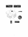
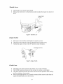
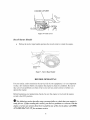
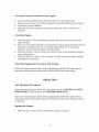
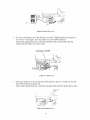
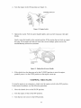
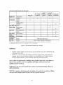
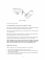
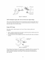
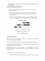
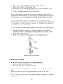
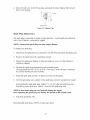
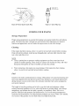
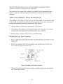
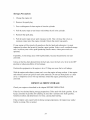
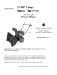
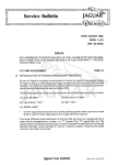
5.5 HP OHV HORIZONTAL
SHAFT ENGINE
i
Item
# 56055
Owner's
Manual
DO NOT
RETURN
Questions?
Please
call our
TO
Problems?
customer
(888) 315-3080
help
line:
M-F 84 CT
Thank you for purchasing this engine. Keep this owner's manual handy, so you can refer to it at
any time. This owner's manual is considered a permanent part of the engine and should remain
with the engine if resold. The information and specifications included in the publication were in
effect at the time of printing.
29
STORE
5.5 HP OHV HORIZONTAL
SHAFT ENGINE
IDEAL
FOR:
• Go Karts
• Generators
• Pumps
• Compressors
• Small Construction
Equipment
• ...And More!
Notice Regarding
Emissions
Engines that are certified to comply with U.S. EPA emission regulations for SORE
(Small Off Road Equipment), are certified to operate on regular unleaded gasoline, and
may include the following emission control systems: (EM) Engine Modifications and
(TWC) Three-Way Catalyst (if so equipped).
TABLE
OF CONTENTS
GENERAL
ENGINE
SAFETY
PROCEDURES
COMPONENTS
PREPARING
Using
THE ENGINE
7
FOR USE ...............................................................
8
8
8
....................................................................................
9
.......................................................................................................
Fuel Valve
Throttle
BEFORE
4
the Engine for the First Time ..................................................................
Add Oil ...........................................................................................
Add Gasoline
CONTROLS
........................................................................
.....................................................................................
9
Lever ........................................................................................
9
Lever ...........................................................................................
10
Engine Switch ...........................................................................................
Choke Lever .............................................................................................
10
10
Recoil
11
Starter
Handle
OPERATING
Check
the General
Check
the Engine
Check
OPERATION
...................................................................................
.........................................................................................
Condition
of the Engine
11
.........................................................
.......................................................................................
12
the Equipment
Powered
By This Engine ....................................................
.....................................................................................................
Safe Operating
Precautions
............................................................................
Starting the Engine ......................................................................................
STOPPING
THE ENGINE .....................................................................................
MAINTENANCE
/ CARE .....................................................................................
Refueling
Engine
Check
12
12
12
12
14
15
.................................................................................................
Oil Level
12
16
................................................................................
17
Engine Oil Change ......................................................................................
Air Filter Maintenance
.................................................................................
18
19
Sediment
................................................................................
20
Spark Plug Maintenance
...............................................................................
STORING
YOUR ENGINE ....................................................................................
21
22
Storage
Cup Cleaning
Preparation
.....................................................................................
22
Cleaning ..................................................................................................
Fuel ........................................................................................................
22
22
Adding
23
A Fuel Stabilizer
to Extend
Fuel Storage
Life .............................................
Draining
the Fuel Tank Carburetor
...................................................................
Storage Precautions
.....................................................................................
REMOVAL
FROM STORAGE
...............................................................................
TRANSPORTING
CARBURETOR
23
24
24
...............................................................................................
MODIFICATION
TROUBLESHOOTING
FOR
HIGH
ALTITUDE
OPERATION
.........................................................................................
25
...........................
25
26
SPECIFICATIONS
..............................................................................................
EXPLODED
VIEW AND PARTS LIST .....................................................................
27
28
WARRANTY
31
.....................................................................................................
GENERAL
SAFETY
PROCEDURES
Please familiarize yourself with the following safety symbols and words:
The safety alert symbol A is used with one of the safety words (DANGER, CAUTION,
or WARNING)
to alert you to hazards. Please pay attention to these hazard notices both
in this manual and on the engine.
DANGER: Indicates a hazard that will result in serious injury or death if instructions are
not followed.
WARNING: Indicates a strong possibility of causing serious injury or death if
instructions are not followed.
CAUTION: Indicates a possibility of personal injury or equipment damage if
instructions are not followed.
O
If you have
manual
any
questions
or on the product,
regarding
please
the hazard
call (888)
and
315-3080
safety
M-F
notices
8-5CT
listed
before
in this
using
the
engine.
A DANGER: This engine produces poisonous carbon monoxide gas when running.
This gas is both odorless and colorless. Even if you do not see or smell gas, carbon
monoxide may still be present.
Breathing this poison can lead to headaches,
dizziness, drowsiness,
and eventually death.
• Use outdoors ONLY in non-confined areas.
•
Keep several feet of clearance
engine..
_k WARNING:
State
of California
The
exhaust
from
to cause
cancer,
on all sides to allow proper ventilation
this product
birth
defects,
contains
or other
chemicals
of the
known
reproductive
to the
harm.
WARNING: This engine may emit highly flammable and explosive gasoline
vapors, which can cause severe burns or even death. A nearby open flame can lead
to explosion
even if not directly
in contact with gas.
• Do not operate near open flame.
• Do not smoke near engine.
• Always operate on a firm, level surface.
• Always turn engine off before refueling. Allow engine to cool for at least 2
minutes before removing fuel cap. Loosen cap slowly to relieve pressure in
tank.
• Do not overfill gas tank. Gas may expand during operation. Do not fill to the top
of the tank.
A
•
•
•
Always check for spilled gas before operating.
Empty gasoline tank before storing or transporting the engine.
Before transporting, turn fuel valve to off and disconnect spark plug.
A WARNING: This engine produces heat when running.
Temperatures
near
exhaust can exceed 150°F (65 ° C).
• Do not touch hot surfaces. Pay attention to warning markings on the engine
denoting hot parts of the machine.
• Allow engine to cool several minutes after use before touching areas that heat
during use.
Owner
•
•
•
responsibilities
The engines are designed to give safe and dependable service if operated
according to instructions. Read and understand this owner's manual before
operating the engine. Failure to do so could result in personal injury or equipment
damage.
Know how to stop the engine quickly, and understand the operation of all
controls. Never permit anyone to operate the engine without proper instructions.
Do not allow children to operate the engine. Keep children and pets away from
the area of operation.
Other Equipment
Review the instructions provided with the equipment powered by this engine for any
additional safety precautions that should be observed in conjunctions with engine startup,
shutdown, operation, or protective apparel that may be needed to operate the equipment.
Engine
Safety
Labeling
In addition to the above safety
hazard markings
on the engine
notices, please familiarize
yourself
as shown on the next page.
with the safety
and
ENGINE
COMPONENTS
Please fiamiliarize yourself with the locations and functions of the various components
and controls of your engine.
0
5
9
2
I1
7
(1) Air cleaner- removable and cleanable sponge
and paper element that limit the amount of dirt
pulled into the engine.
(2) Fuel Valve Lever- Controls flow of fuel into the
engine.
(3) Choke lever- Adjusts the alnount of air let into
the engine.
(4) Spark plug- Provides proper engine ignition.
(5) Muffler- Reduces engine noise.
(6) Throttle Lever- Use to control engine speed.
(7) On/Off Switch- Used to start/stop engine.
-I2
(8) Recoil Starter Handle- Pull-cord for starting
engine.
(9) Fuel Cap- Access to the fuel tank for adding fuel.
(10) Fuel Tank- Stores gas used to run engine.
(11) Oil Fill and Dipstick- Location for checking and
filling engine oil.
(12) Oil Drain Plug- Location for draining oil.
PREPARING
Using
the Engine
The following
first-time
use.
to perform
for the First Time
section
If after
of the steps please
these
THE ENGINE FOR USE
describes
reading
steps you
this" section,
315-3080
call (888)
steps properly
must follow
to prepare
you are unsure
about
your
engine
or shorten
engine
how to perform
M-F 8-5 CT for customer
can damage
your
service.
for
any
Failure
its"life.
If you are using the engine for the first time, there are a few steps you must take to
prepare it for operation:
Add Oil
The engine requires engine oil to operate properly. The engine, when new from the
carton, contains no oil in the crankcase. You must add the proper amount ofoil before
operating the engine for the first time. This amount, which is equal to the oil capacity of
the crankcase, is 20.2 fluid oz.
For general use, we recommend SAE 10W/30 oil to fill the engine crankcase.
To add
1.
2.
3.
4.
oil, follow these steps:
Make sure the engine is on a level surface.
Unscrew the oil filler/dipstick cap from the engine as shown in figure 1.
Using a funnel, add 20.2 fluid ounces ofoil into the crankcase. You will know
the crankcase is full when the oil level has reached the lower lip of the opening
you have just poured the oil into (see figure 2).
Replace oil filler cap.
_iLLER
Figure
CAFTDiPST_CK
1- Unscrewing
the oil cap
Figure 2- Adding oil
Add
Gasoline
A WARNING:
Gasoline
and gas fumes are highly flammable.
•
Do not fill tank near an open flame.
•
Do not overfill. Always check for fuel spills.
To ensure that the engine runs smoothly use only FRESH, U_,,TLEADED GAS WITH AN
OCTANE RATING OF 87 OR HIGHER. To add gasoline:
1. Make sure the engine is on a level surface.
2. Unscrew gas cap and set aside (NOTE: the gas cap may be tight and hard to
unscrew).
3. Slowly add unleaded gasoline to the fuel tank. The capacity of the gas tank is 0.95
gallons. Be careful not to overfill. NOTE: Gas can expand. Do not fill the gas tank
to the very top.
4. Replace fuel cap and wipe up any spilled gasoline with a dry cloth.
IMPORTANT:
•
•
•
•
Never use an oil/gasoline mixture.
Never use old gas.
Avoid getting dirt or water in the fuel tank.
Gas can age in the tank and make it hard to start up the engine in the future. Never
store engine for extended periods of time with fuel in the tank.
CONTROLS
Fuel
•
•
•
Valve Lever
The fuel valve opens and closes the line between the fuel tank and the carburetor.
The fuel valve lever must be in the ON position for the engine to run.
When the engine is not in use, leave the fuel valve lever in the OFF position to
prevent carburetor flooding and to reduce the possibility of fuel leakage.
OFF
OFF
Figure 3- Fuel Valve Lever
Throttle
•
•
Lever
The throttle lever controls engine speed.
Moving the throttle lever in the directions
faster.
shown makes the engine run slower or
LEVER
SLOW
Figure 4- Throttle
Engine
•
•
•
Lever
Switch
The engine switch enables and disables the ignition system.
The engine switch must be in the ON position for the engine to run,
Turning the engine switch to the OFF position stops the engine.
ENGINE SWITCH
OFF
Figure 5- Engine Switch
Choke Lever
•
•
•
•
The choke lever opens and closes the choke valve in the carburetor.
The CLOSE position enriches the fuel mixture for starting a cold engine.
The OPEN position provides the correct fuel mixture for operation after starting,
and for restarting a warm engine.
Some engine applications use a remotely-mounted choke control rather than the
engine-mounted choke lever shown here.
10
CHOKE LEVER
CLO
Figure
Recoil
•
Starter
6- Choke
Lever
Handle
Pulling the starter rope handle operates the recoil starter to crank the engine.
STARTERROPE
HANDLE
Figure
7- Starter
BEFORE
Rope
Handle
OPERATING
For your safety, and to maximize the service life of your equipment, it is very important
to take a few moments before you operate the engine to check its condition. Be sure to
take care of any problem you find, or have your service center correct it, before you
operate the engine.
Before beginning your preparation
switch is the OFF position.
The following
ready for
engine,
315-3080
use.
section
If after
describes
reading
or if you are unsure
M-F
8-5
CT for
checks, be sure the engine is level and the engine
steps you
this section,
about
must follow
you
how to perform
customer
service.
11
to check
discoverproblems
that your
engine
or concerns
any of the checks
please
is
with the
call (888)
Check
•
•
•
•
the General
•
•
•
of the Engine
Look around and underneath the engine for signs of oil or gasoline leaks.
Remove any excessive dirt or debris, especially around the muffler and recoil starter.
Look for any signs of damage
Check that all shields and covers are in place and all nuts, bolts, and screws are
tightened
Check
•
Condition
the Engine
Check the engine oil level. Running the engine with a low oil level can cause the
engine damage.
The Low Oil Automatic Shutoff will automatically stop the engine before the oil level
falls below safe limits. However, to avoid the inconvenience
of an unexpected
shutdown, always check the engine oil before startup.
Check the air filter. A dirty air filter will restrict air flow to the carburetor, reducing
engine performance.
Check the fuel level. Starting with a full tank will help eliminate or reduce operating
interruptions for refueling.
Check
the Equipment
Powered
by This
Engine
Review the instructions provided with the equipment powered by this engine for any
precautions and procedures that should be followed before the engine startup.
OPERATION
Safe
Operating
Before operating
PROCEDURES
Precautions
the engine for the first time, please review the GENERAL
and the chapter entitled BEFORE OPERATING.
SAFETY
Review the instructions provided with the equipment powered by this engine for any
safety precautions that should be observed in conjunction with engine startup, shutdown,
or operation.
Starting
the Engine
1. Move the fuel valve lever to the ON position
12
as shown in figure 8.
OFF
Figure
.
8- Fuel Valve Lever
To start a cold engine, move the choke lever to the CLOSED position (see figure 9).
To restart a warm engine, leave the choke lever in the OPEN position.
Some engine applications use a remotely-mounted
choke control rather than the
engine-mounted
choke lever shown here.
CHOKE LEVER
OPEN
CLOS
/,,_
Figure
.
9- Choke
)
Lever
Move the throttle lever away from the SLOW position, about 1/3 of the way toward
the FAST position (see figure 10).
Some engine applications use a remotely-mounted
rather than the throttle shown here.
THROTTLE
LEVER
SLOW
/
Figure
10- Throttle
13
Lever
4.
Turn the engine to the ON position (see figure 11).
ENGINE SWITCH
ON
Figure 11- Engine Switch
.
Operate the starter. Pull the starter handle lightly until you feel resistance,
briskly.
then pull
Gently return the handle to the original position. If the engine does not start up, repeat
this step. If the engine still does not start after several sttenpts, please review the
troubleshooting
section for assistance.
Figure
.
12- Pulling
Recoil
Starter
Handle
If the choke lever has been moved to the CLOSED position to start the engine,
gradually move it to the OPEN position as the engine warms up.
STOPPING
THE
ENGINE
To stop the engine in an emergency, simply turn the engine switch to the OFF position
Under normal conditions, use the following procedure.
1. Move the throttle lever to the SLOW position.
2.
Turn the engine switch to the OFF position.
3.
Turn the fuel valve lever to the OFF position.
14
MAINTENANCE/CARE
Good maintenance is essential
also help reduce air pollution.
for safe, economical,
and trouble-free
operation.
It will
To help you properly care for your engine, the following pages include a maintenance
schedule, routine inspection procedures, and simple maintenance procedures using basic
hand tools. Other service tasks that are more difficult, of require special tools, are best
handled by professionals and are normally performed by a technician or qualified
mechanic.
The maintenance schedule
operate your engine under
temperature operation, or
maintenance schedule for
more frequently.
in figure 13 applies
unusual conditions,
use in unusually wet
oil change, air filter,
to normal operation conditions. If you
such as sustained high-load or highor dusty conditions, perform the routine
sediment cup, and spark plug cleaning
If you have questions about any of the maintenance
manual, please call (888) 315-3080 M-F 8-5CT.
procedures
listed in this
CAUTION:
•
Never perform
maintenance
operations
•
To reduce the possibility of fire or explosion, be careful when working
around gasoline. Use only a nonflammable
solvent, not gasoline, to clean
parts. Keep cigarettes, sparks and flames away from all fuel-related parts.
•
To ensure the best quality and reliability, use only new, genuine parts or
their equivalents
for repair or replacement.
15
while the engine is running.
Recommended
Maintenance Schedule
each use
Engine oil
sheck level
Air cleaner
"eplace
sheck
first month
or20 hrs
every 3
months or
50 hrs
every6
months or
100 hrs
every year
or 300 hrs
X
slean
X
"eplace paper
Nement
X
Fuel filter cup slean
sheck/clean
Spark plug
X
X
X
"eplace
Gas tank
sheck gas level
slean
X*
Idle speed
Valve
clearance
Combustion
chamber
sheck-adjust
X*
sheck-adjust
X*
Slean
After every 300 hours*
Fuel line
Sheck
Every 2 years (replace if necessary)*
* These items should be serviced by your servicing center unless you have the proper tools and are
mechanically proficient. Refer to the manual for service procedures.
Figure
13- Recommended
maintenance
schedule
Refueling
1. With the engine stopped, remove the gas cap and check the gas level. Refill the tank
if the gas level is low.
2. Refuel in a well-ventilated
area before starting the engine. If the engine has been
running, allow it to cool. Refuel carefully to avoid spilling fuel. Do not fill above
the fuel strainer shoulder. After refueling, tighten the fuel cap securely.
Never refuel the engine inside a building where gasoline fumes may reach flames
sparks. Keep gasoline away from appliance pilot lights, barbecues,
electronic
appliances,
power tools, etc.
Spilled gas is not only a fire hazard
spills immediately.
but it causes environmental
damage.
or
Wipe up
NOTICE: Gasoline can damage paint and plastic. Be careful not to spill when filling
your gas tank. Damage caused by gas is not cover under warranty.
16
Figure 14- Adding Gas
FUEL
_(
'OMMENDA
Use unleaded
TIONS'
gasoline with a pump
octane rating
of 87 or higher.
These engines are certified to operate on unleaded gasoline. Unleaded gasoline produces
fewer engine and spark plug deposits and extends exhaust system life.
Never use stale or contaminated gasoline or an oil/gasoline mixture. Avoid getting dirt or
water in the fuel tank.
Occasionally you may hear a light "spark knock" or "pinging" (metallic rapping noise)
while operating under heavy loads, this is no cause for concern.
If a spark knock or pinging occurs at a steady engine speed, under normal load, change
brands of gasoline. If spark knock or pinging persists, see your servicing center.
NOTE: Running the engine with persistent spark knock or pinging can cause engine
damage. Running the engine with persistent spark knock or pinging is considered
misuse, and the Limited Warranty does not cover parts damaged by misuse.
Engine
Oil Level
Check
Check the engine oil level with the engine stopped and in a level position.
1. Remove the filler cap/dipstick and wipe it clean (see figure 15).
2. Insert and remove the dipstick without screwing it into the filler neck, Check the oil
level shown on the dipstick.
3. If the oil level is low, fill to the edge of the oil filter hole with the recommended oil.
4. Screw in the filler cap/dipstick securely.
17
FILLER
CAP/DIPSTICK
LOWER
Figure 15- Checking
NOTE:
Running
L[MFF
Oil
the engine with a low level oil can cause engine damage.
The Low Oil Automatic Shutoff system will automatically stop the engine before the oil
level falls below safe limit. However, to avoid the inconvenience of a shutdown, always
check the engine oil level before startup.
Engine
Oil Change
Drain the used oil while the engine is still warm. Warm oil drains quickly and
completely.
1. Place a suitable container below the engine to catch the used oil, and then remove the
filler cap/dipstick and then drain the plug.
2. Allow the used oil to drain completely, and then reinstall the drain plug, and tighten it
securely.
• '.
/
FILLER CAP/
DIPSTICK
Figure
16- Draining
Oil
Please dispose of used motor oil in a manner that is compatible with the environment. We
suggest you take the used oil in a sealed container to your local recycling center or
service station for reclamation. Do not throw it in the trash, pour it on the ground, or
down the drain.
18
3.
With the engine in a level position,
recommended oil.
fill to the outer edge of the oil filler hole with the
4. Screw in the filler cap/dipstick securely.
ENGINE OIL RECOMMENDATIONS
•
Oil is a major factor affecting performance
automotive detergent oil.
and service life. Use 4-stroke
•
SAE 10W-30 is recommended for general use. Other viscosities shown in the
chart may be used when the average temperature in your area is within the
recommended range.
•
The SAE oil viscosity and service classification are in the API label on the oil
container. We recommend that you use API SERVICE Category SE or SF oil.
SAE Viscosity Grades
-20
0
20
40
60
80
100°F
L
2
I
_
L
,J
J
-30
-20
-i0
0
10
28
30
!
40°C
AMBEENT TEMPERATURE
Figure
Air
Filter
17- Oil Recommendations
Maintenance
Remove the air cleaner cover and inspect the filter. Clean or replace dirty filter elements.
Always replace damaged filter elements.
A dirty air filter will restrict air flow to the carburetor,
reducing
engine performance.
If you operate the engine in very dusty areas, clean the air filter more often than specified
in the MAINTENANCE
SCHEDULE.
NOTE: Operating the engine without an air filter, or with a damaged air filter, will allow
dirt to enter the engine, causing rapid engine wear. This type of damage is not covered by
Limited Warranty.
To service the air filter, perform the following
steps:
1. Remove the wing nut from the air cleaner cover, and remove the air cleaner cover.
19
2.
3.
4.
5.
Remove the wing nut from the air filter, and remove the filter.
Remove the foam filter from the paper filter.
Inspect both air filter elements, and replace them if they are damaged.
replace the paper air element at the scheduled interval.
Clean the air filter elements if they are to be reused.
Always
Paper air filter element: Tap the filter element several times on a hard surface to
remove dirt, or blow compressed air [not exceeding 30psi] through the filter element
from the inside. Never try to brush off dirt; brushing will force dirt into the fibers.
Foam air filter element: Clean in warm soapy water, rinse, and allow drying
thoroughly. Or clean in nonflammable
solvent and allow to dry. Dip the filter element
in clean engine oil, and then squeeze out all excess oil. The engine will smoke when
started if too much oil is left in the foam.
6.
7.
8.
Wipe dirt from the inside of the air cleaner base and cover, using a moist rag. Be
careful to prevent dirt from entering the air duct the leads to the carburetor.
Place the foam air filter element over the paper element, and reinstall the
assembled air filter. Be sure the gasket is in place beneath the air filter. Tighten
the air filter wing nut securely.
Install the air cleaner cover, and tighten the cover wing nut securely.
PA_ER
FI_ER
ELEMENT
FOA_
FtETER
ELEMENT
Figure
Sediment
Cup
tL WARNING:
•
•
18- Air Filter
Components
Cleaning
Gasoline
and gas fumes are highly flammable.
Do not fill tank near an open flame.
Do not overfill. Always check for fuel spills.
1. Move the fuel valve to the OFF position, and then remove the sediment cup and Oring.
2. Wash the sediment cup and O-ring in nonflammable
solvent, and dry them
thoroughly.
3. Place the O-ring in the fuel valve, and install the sediment cup. Tighten the sediment
cup securely.
2O
4.
Move the fuel valve to the ON position,
there is any leakage.
and check for leaks. Replace the O-ring if
SE© M_NT C.JP
Figure
Spark
Plug
19- Sediment
(;up
Maintenance
The spark plug is important for proper engine operation.
intact, free of deposits, and properly gapped.
NOTE: An incorrect
A good spark plug should be
spark plug can cause engine damage.
To inspect you spark plug:
1. Disconnect
the spark plug wire, and remove
any dirt from around the spark plug area.
2.
Remove the spark plug with a spark plug wrench.
3.
Inspect the spark plug. Replace it if the electrodes
cracked or chipped.
4.
Measure the spark plug electrode gap with a suitable gauge.
The gap should be 0.028 -0.031 in (0.70 - 0.80 mm). Correct the gap, if necessary,
by carefully bending the side electrode.
5.
Install the spark plug carefully,
6.
After the spark plug seats, tighten with a spark plug wrench to compress
are worn, or if the insulator
is
by hand, to avoid cross-threading.
the washer.
If reinstalling the used spark plug, tighten 1/8 -1/4 turn after the spark plug seats.
If installing a new spark plug, tighten 1/2turn after the spark plug seats.
NOTE:A loose spark plug can over heat and damage the engine.
Over tightening the spark plug can damage the threads in the cylinder
7.
Attach the spark plug wire.
Recommended
spark plugs: F6RTC or other equivalents.
21
head.
SPARK PLUG WRENCH
(070080
i
Figure 20- Removing the Spark Plug
STORING
Storage
4_
ram}
0,028-0031 :n:
Figure 21- Spark Plug Gap
YOUR ENGINE
Preparation
Proper storage preparation is essential for keeping your engine trouble free and looking
good. The following steps will keep rust and corrosion from impairing your engine's
function and appearance, and will make the engine easier to start after storage.
Cleaning
If the engine had been running, allow it to cool for at least half an hour before cleaning.
Clean all exterior surfaces, touch up any damaged paint, and coat other areas that may
rust with a light film ofoil.
NOTE
• Using a garden hose or pressure washing equipment can force water into the air
cleaner or muffler opening. Water in the air cleaner will soak the air filter, and water
that passes through the air filter of muffler can enter the cylinder.
•
Water contacting a hot engine can cause damage. If the engine has been running,
allow it to cool for at least half an hour before washing.
Fuel
Gasoline will oxidize and deteriorate in storage. Old gasoline will cause hard starting and
leaves gum deposits that clog the fuel system. If the gasoline in your engine deteriorates
during storage, you may need to have the carburetor and other fuel system components
serviced or replaced.
The length of time that gasoline can be left in your fuel tank and carburetor without
causing functional problems will vary with such factors as gasoline blend, your storage
temperature, and whether the fuel tank is partially or completely filled. The air in a
partially filled fuel tank promotes fuel deterioration. Very warm storage/temperatures
accelerate fuel deterioration. Fuel deterioration problems may occur within a few months,
or even less if the gasoline was not fresh when you filled the fuel tank.
22
The Limited Warranty does not cover fuel system damage or engine performance
problems resulting from neglected storage preparation.
You can extend fuel storage life by adding a fuel stabilizer that is formulated for that
purpose, or you can avoid fuel deterioration problems by draining the fuel tank and
carburetor.
Adding
a Fuel
Stabilizer
to Extend
Fuel
Storage
Life
When adding a fuel stabilizer, fill the fuel tank with fresh gasoline. If only partially filled,
air in the tank will promote fuel deterioration during storage. If you keep a container of
gasoline for refueling, be sure that it contains only fresh gasoline.
1. Add fuel stabilizer
following
the manufacturer's
instructions.
2.
After adding a fuel stabilizer, run the engine outdoors forl0 minutes to be sure that
treated gasoline has replaced the untreated gasoline in the carburetor.
3.
Stop the engine, and move the fuel valve to the OFF position.
Draining
the Fuel
Tank
Carburetor
1. Place an approved gasoline container
spilling fuel.
2.
below the carburetor
and use a funnel to avoid
Remove the carburetor drain bolt and sediment cup, and then move the fuel valve
lever to the ON position (see figure 22).
FUEL VALVE LEVER
()-RING
Figure 22- Draining the Fuel Tank Carburetor.
.
After all the fuel has drained into the container, reinstall the drain bolt and sediment
cup. Tighten them securely.
23
Storage
Precautions
1. Change the engine oil.
2.
Remove the spark plug.
3.
Pour a tablespoon
4.
Pull the starter rope several times to distribute
5.
Reinstall
6.
Pull the starter rope slowly until resistance is felt. This will close the valves so
moisture cannot enter the engine cylinder. Return the starter rope gently.
of clean engine oil into the cylinder
the oil in the cylinder.
the spark plug.
If your engine will be stored with gasoline in the fuel tank and carburetor, it is most
important to reduce the hazard of gasoline vapor ignition. Select a well-ventilated
storage
area. Avoid any area with a spark-producing
electric motor, where power tools are
operated.
If possible, avoid storage areas with high humidity,
corrosion.
because that promotes
rust and
Unless all fuel has been drained form the fuel tank, leave the fuel valve lever in the OFF
position to reduce possibility of fuel leakage.
Position the equipment
so the engine is level. Tilting can cause fuel or oil leakage.
With the engine and exhaust system cool, cover the engine to keep out dust. A hot engine
and exhaust system can ignite or melt some materials. Do not use sheet plastic as a dust
cover. A nonporous cover will trap moisture around the engine, promoting rust and
corrosion.
REMOVAL
Check your engine as described
FROM
STORAGE
in the chapter BEFORE
OPERATING.
If the fuel was drained during storage preparation, fill the tank with fresh gasoline. If you
keep a container of gasoline for refueling, be sure that it contains only fresh gasoline.
Gasoline oxidizes and deteriorates over time, causing hard starting.
If the cylinders were coated with oil during storage preparation,
briefly at startup. This is normal.
24
the engine may smoke
TRANSPORTING
If the engine has been running, allow it to cool for at least 15 minutes before loading the
engine-powered
equipment on the transport vehicle. A hot engine and exhaust system can
burn you and can ignite some materials.
Keep the engine level when transporting to reduce the possibility of fuel leakage. Move
the fuel valve lever to the OFF position.
CARBURETOR
MODIFICATION
OPERATION
FOR
HIGH
ALTITUDE
At high altitude, the standard carburetor air-fuel mixture will be too rich. Performance
will decrease, and fuel consumption will increase. A very rich mixture will also foul the
spark plug and cause hard starting. Operation at an altitude that differs form that at which
this engine was certified, for extended periods of time, may increase emissions.
High altitude performance can be improved by specific modifications to the carburetor. If
you always operate your engine at altitudes above 5,000 feet (1,500 meters), have your
servicing center perform this carburetor modification. This engine, when operated at high
altitude with the carburetor modified for high altitudes use, will meet each emission
standard throughout its useful life.
Even with carburetor modification, engine horsepower will decrease about 3.5% for each
1,000-foot (300-meter) increase in altitude. The effect of altitude in horsepower will be
greater then this if no carburetor modification is made.
NOTE
When the carburetor
has" been modiJied
will be too lean for a low altitude
for high altitude
use. Operation
operation,
at altitudes'
below
the air-_lel
5, O00 feet
mixture
(1,500
meters) with modified carburetor
may cause the engine to overheat
and result in serious
engine damage. For use at low altitudes', have your servicing
center return the
carburetor
to original
factol_v
specifications.
25
TROUBLESHOOTING
IMPORTANT:
M-F 8-5.
Engine Will Not
Start
1. Check control
positions
If trouble persists please call our customer
Solution
Cause
Fuel valve OFF.
Move lever to "ON" position.
Shoke OPEN.
Move lever to "CLOSED" position unless engine is warm.
Turn engine switch to "ON" position.
Engine switch OFF.
2. Check fuel.
help line at (888) 315-3080
Engine is out of gas. Add gas.
Engine is filled with Change the gas in the engine.
sontaminated or old
_las
3. Check oil.
4. Remove and
inspect spark
plug.
5. Take engine to
an authorized
servicing dealer.
Engine Lacks
Power
_ow engine oil level
automatic shutoff
_=ngaged.
Spark plug is dirty,
Faulty, or improperly
;lapped.
Spark plug is wet
_vithgas (flooded
_=ngine).
Fuel filter clogged,
sarburetor
*nalfunction, ignition
*nalfunction, valve
stuck, etc.
Fill crankcase with proper oil.
Gap, clean, or replace spark plug.
Dry and reinstall spark plug. Start engine with throttle lever in
the "FAST" position.
Replace or repair faulty components as necessary.
Cause
Solution
1. Check air filter.
Filter elements
slogged.
Clean or replace filter elements.
2. Check Gas
Engine is filled with
sontaminated or old
;las
Change the gas in the engine.
3. Take engine to Fuel filter clogged,
Replace or repair faulty components as necessary.
an authorized
sarburetor
servicing center or *nalfunction, ignition
refer to manual.
*nalfunction, valve
stuck, etc.
26
SPECIFICATIONS
Engine Type
LxWxH (in)
4-Stroke,
Overhead
12 x 14-3/8 x 13-3/16 (305mm x 365 mm x 335 mm)
30.8 lbs
Dry Weight
Displacement
Bore x Stroke]
Compression Ratio
Maximum
Valve, Single Cylinder
Output
Maximum Torque
9.9 cubic in. (163 cubic cm)
[2.7 in x 1.8 in (68 mm x 45 mm)]
8.5:1
5.5 HP @ 3600 RPM
6.63 ft. lbs (a) 3000 RPM
Engine Oil Capacity
20.2 fl. oz. (0.6 L)
Engine Oil Type
Fuel Tank Capacity
SAE 10W-30, API SE or SF, for general use
0.95 gal (3.6 L)
Cooling System
Forced air
[gnition System
P.Y.O. (in)
Transistorized Magneto Ignition
2-7/16 x 3/4dia. Tapped 5/16 24 U2',TF
P.T.O. Shaft Rotation
Counterclockwise
(from P.T.O. side)
IN: 0.15 (+) 0.02 mm (cold)
EX: 0.20 (+) 0.02 mm (cold)
Valve Clearance
Spark Plug Type
Spark Plug Gap
F6TC or equivalent
0.028-0.031
Carburetor Idle Speed
in (0.70-0.80
1700 (+) 150 rpm
27
mm)
>
>
Item
1
2
3
4
5
6
7
8
9
i0
ii
12
13
14
15
16
i?
18
19
2O
21
22
23
24
25
26
2?
28
29
3O
31
32
33
34
35
36
3?
38
39
4O
41
42
43
44
45
46
4?
48
49
5O
51
52
53
54
55
56
5?
Part#
11212
Qty
Oil drain plug
Washer
13180
1
1
Bearing 6205
Crankshaft
oil seal
11100
1
Crankcase
26311
26329
1
1
Regulating
Washer
26321
1
Split pin
37810
1
Oil sensor
GB5787-86
2
M6×14
25151
25165
1
1
Regulating
Washer
25120
1
Regulator
25164
25132
1
1
Snap ring
Washer
25131
1
Sleeve
GB5787-86
6
M6× 12 bolt
20651
1
Air duct
19721
1
Wind cover
12252
2
M6 X 113 bolt
12218
2
1
Set pin d_ 10X 16
Cylinder head gasket
12253
1
2
Cylinder head Assembly
M8 X 34 bolt
34200
1
Spark plug
12256
4
Bolt
12312
1
Cylinder
head cover
gasket
12310
1
Cylinder
head cover
assembly
15650
1
Oil plug assembly
15651
15612
1
2
Oil plug
Seal
11311
1
Crankcase
GB276-89
1
Bearing
11119
1
Crankcase
11118
2
Set pin
15611
1
Oil dipstick
15610
13180
1
1
Oil dipstick assembly
Crankshaft
oil seal
GB5787-86
7
M8 X 32 bolt
11213
GB276-89
12220
12210
sway bar
bolt
shaft
gear assembly
cover
6205
gasket
13311
1
Piston
13312
13322
1
2
Piston ring ( II )
Side rail
13321
1
Expander
ring ( I )
13320
1
Scraper
13300
1
Piston
ring assembly
13222
2
1
Piston
Piston
pin clip
1
1
Piston
Shank
pin
Connecting
Bolt
rod cover
13133
1
2
13130
1
Connecting
rod assembly
13118
1
Woo&uffkey
13110
14416
1
2
Crankshaft
Lock nut
14413
2
Sleeve
14411
2
Valve
13211
13221
13131
13132
Item
58
59
6O
61
62
63
64
65
66
67
68
69
70
71
72
73
74
75
76
77
78
79
8O
81
82
83
84
85
86
87
88
89
9O
91
92
93
94
95
96
97
98
99
IO0
i01
102
I03
104
I05
106
I07
I08
109
ii0
iii
112
113
Description
2
2
ring set
assembly
rocker
29
Part#
Qty
Description
14415
2
Adjusting
14410
2
Valve
rocker
14261
Pusher
Pusher
guide
14250
1
2
14455
2
Tappet
14100
14721
1
1
Camshaft assembly
Exhaust valve
14711
1
Intake
valve
14755
2
Valve
spring
14751
1
Intake
valve spring
14757
1
Exhaust
14758
1
Cap
12254
1
Inlet gasket
16141
1
Connecting
block
16142
1
Carburetor
gasket
17330
1
Air cleaner
gasket
16100
17100
1
1
Carburetor
assembly
Air cleaner
GB6177-86
2
M6 nut
16937
2
Pipe clamp
16931
1
Outlet
GB5787-86
1
M6 X 22 bolt
16950
1
Connector
16961
GB6177-86
1
2
Packing
M6 nut
16916
1
Filter cup
16521
1
Packing
16510
1
Fuel cap
16500
16610
1
1
Fuel cap with assembly
Fuel tank
18000
1
Exhaust
nmffler
12255
1
1
Exhaust
M6 nut
gasket
GB6177-86
GB5787-86
1
M6×22
19810
1
Crankcase
GB5787-86
3
M6 X 8 bolt
19710
27300
1
1
Fan hood assembly
Recoil starter
GB5787-86
5
M6X
35410
1
Engine
switch
27100
1
Recoil
starter
32211
Plastic
Diode
clip
37850
1
1
26410
1
Regulating
26363
1
Back spring
26364
1
Regulating
26341
1
1
Pulling rod
Lock bolt
GB6177-86
1
1
Regulating
M6 nut
GB5787-86
2
M6 X 25 screw
27515
1
M14 X 1.5 nut
27370
1
Starting
flange
19722
1
Flywheel
tim
27500
1
Flywheel
34500
1
Ignition
26362
26331
bolt for valve gap
assembly
seat
valve spring
seat
pipe
ring
ring
bolt
side plate assembly
12 bolt
assembly
frame assembly
spring
arm
coil assembly
NOTES:
30
LIMITED
WARRANTY
Remember
to save your
registration
Power
card.
FOR POWER
receipt
TM
ENGINES
and to accurately
You must provide
Pro "_ engines
PRO
are warranted
proof
FROM WEN POWER
TM
Jill out and mail your product
of purchase
for all warranty
to be free from defects
in materials
work.
and workmanship
for a period of one (1) year from date of original purchase.
Engines used for Commercial
or Rental use have a warranty period of 90 days from date of original purchase.
Keep
purchase
receipt
and mail in the product
registration
card for proof
of purchase.
Power Pro by WEN Power will repair or replace, at its discretion, any part that is
proven to be defective in materials or workmanship under normal use during the one (1)
year warranty period. Warranty repairs or replacements will be made without charge for
parts or labor. Parts replaced during warranty repairs will be considered as part of the
original product and will have the same warranty period as the original product.
TM
TM
To exercise the warranty, DO NOT RETURN TO RETAILER.
Instead, call the toll
free Customer Service number: (888) 315-3080 and you will be instructed on where to
take the engine for warranty service. Take the engine and proof of purchase (your
receipt) to the repair facility recommended by the Customer Service Representative.
The warranty does not extend to engines damaged or affected by fuel contamination,
accidents, neglect, misuse, unauthorized alterations, use in an application for which the
product was not designed and any other modifications or abuse.
Power Pro "_ by WEN Power is not liable for any indirect, incidental or consequential
damages from the sale or use of this product. Any implied warranties are limited to one
(1) year as stated in this written limited warranty. Some states do not allow the exclusion
or limitation of incidental or consequential damages. Some states do not allow limitation
on the length of an implied warranty. This warranty gives you specific legal rights, and
you may have other rights that vary from state to state.
TM
Power Pro by Wen Power
TM.
Elgin, IL 60123.
31
www.wenproducts.com.