1
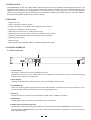
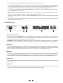
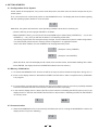
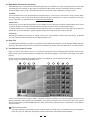
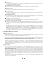
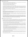
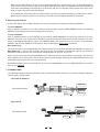
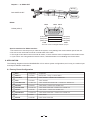
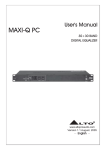
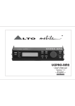
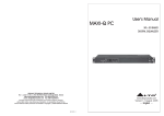
User's Manual
MAXIDRIVE3.4 PC
3 WAY STEREO
DIGITAL CROSSOVER
R
LTO
www.altoproaudio.com
Version 1.5 February 2006
English
Fuse
SAFETY RELATED SYMBOLS
To prevent fire and damage to the product, use only
the recommended fuse type as indicated in this
manual. Do not short-circuit the fuse holder. Before
replacing the fuse, make sure that the product is
OFF and disconnected from the AC outlet.
CAUTION
RISK OF ELECTRIC SHOCK
DO NOT OPEN
This symbol, wherever used, alerts you to the presence of un-insulated and dangerous voltages within the product enclosure. These are voltages that
may be sufficient to constitute the risk of electric
shock or death.
Protective Ground
Before turning the product ON, make sure that it is
connected to Ground. This is to prevent the risk of
electric shock.
This symbol, wherever used, alerts you to important operating and maintenance instructions.
Please read.
Never cut internal or external Ground wires. Likewise,
never remove Ground wiring from the Protective
Ground Terminal.
Protective Ground Terminal
Operating Conditions
AC mains (Alternating Current)
Always install in accordance with the manufacturer's
instructions.
Hazardous Live Terminal
ON:
To avoid the risk of electric shock and damage, do
not subject this product to any liquid/rain or moisture.
Do not use this product when in close proximity to
water.
Denotes the product is turned on.
OFF: Denotes the product is turned off.
WARNING
Do not install this product near any direct heat source.
Describes precautions that should be observed to
prevent the possibility of death or injury to the user.
Do not block areas of ventilation. Failure to do so
could result in fire.
CAUTION
Keep product away from naked flames.
Describes precautions that should be observed to
prevent damage to the product.
IMPORTANT SAFETY INSTRUCTIONS
Read these instructions
Disposing of this product should not be
placed in municipal waste and should be
Separate collection.
Follow all instructions
Keep these instructions. Do not discard.
Heed all warnings.
WARNING
Only use attachments/accessories specified by the
manufacturer.
Power Supply
Ensure that the mains source voltage (AC outlet)
matches the voltage rating of the product. Failure
to do so could result in damage to the product and
possibly the user.
Power Cord and Plug
Do not tamper with the power cord or plug. These are
designed for your safety.
Unplug the product before electrical storms occur
and when unused for long periods of time to reduce
the risk of electric shock or fire.
Do not remove Ground connections!
External Connection
Protect the power cord and plug from any physical
stress to avoid risk of electric shock.
If the plug does not fit your AC outlet seek advice from
a qualified electrician.
Always use proper ready-made insulated mains
cabling (power cord). Failure to do so could result
in shock/death or fire. If in doubt, seek advice from
a registered electrician.
Do not place heavy objects on the power cord. This
could cause electric shock or fire.
Cleaning
When required, either blow off dust from the product
or use a dry cloth.
Do Not Remove Any Covers
Within the product are areas where high voltages
may present. To reduce the risk of electric shock do
not remove any covers unless the AC mains power
cord is removed.
Do not use any solvents such as Benzol or Alcohol.
For safety, keep product clean and free from dust.
Servicing
Covers should be removed by qualified service
personnel only.
No user serviceable parts inside.
Refer all servicing to qualified service personnel only.
Do not perform any servicing other than those instructions contained within the User's Manual.
1
PREFACE
Dear Customer:
Thanks for choosing MAXIDRIVE3.4 PC 3 - Way Stereo Digital Crossover and thanks for choosing one of the results
of LTO AUDIO TEAM job and researches.
For our
LTO AUDIO TEAM, music and sound are more than a job...are first of all passion and let us say our obsession!
We have been designing professional audio products for a long time in cooperation with some of the major brands
in the world in the audio field.
The LTO line presents unparalleled analogue and digital products made by Musicians for Musicians in our R&D
centers in Italy, Netherlands, United Kingdom and Taiwan. The core of our digital audio products is a sophisticated
DSP (Digital Sound Processor) and a large range of state of the art algorithms which have been developed by our
Software Team for the last 8 years.
Because we are convinced you are the most important member of LTO AUDIO TEAM and the one confirming the
quality of our job, we would like to share with you our work and our dreams, paying attention to your suggestions and
your comments.
Following this idea we create our products and we will create the new ones! From our side, we guarantee you and
we will guarantee you also in future the best quality, the best fruits of our continuous researches and the best prices.
Our MAXIDRIVE3.4 PC 3 - Way Stereo Digital Crossover is the result of many hours of listening and tests involving
common people, area experts, musicians and technicians. The results of this effort is a DSP hi-performance equalizer
that can be used in applications as musical performances, Installation and sound reinforcement. Besides we offer to
you a number of factory EQ curves that we collected and transformed in presets now available in our small, efficient
and easy to use MAXIDRIVE3.4 PC.
Nothing else to add, but that we would like to thank all the people that made the MAXIDRIVE3.4 PC a reality available
to our customers, and thank our designers and all the LTO staff, people who make possible the realization of products containing our idea of music and sound and are ready to support you, our Customers, in the best way, conscious
that you are our best richness.
Thank you very much
LTO AUDIO TEAM
2
TABLE OF CONTENTS
1. INTRODUCTION .....................................................................................................................................4
2. FEATURES .............................................................................................................................................4
3. CONTROL ELEMENTS .........................................................................................................................4
3.1 The Front Panel
3.2 The Rear Panel
4. GETTING STARTED ...............................................................................................................................6
4.1 Configuration of the System
4.2 Memory Initialization
4.3 Communication
4.4 First Steps with the PC Editor
4.5 Edit Mode
4.6 Help File
4.7 Introduction to the PC Editor
5. PARAMETER MENUS DESCRIPTION ..................................................................................................9
6. WORKING WITH PRESETS ..............................................................................................................12
7. CONNECTIONS .................................................................................................................................12
8. APPLICATION .....................................................................................................................................13
8.1 Factory Preset Configuration
8.2 Organization
9. TECHNICAL SPECIFICATIONS .........................................................................................................19
10. WARRANTY ........................................................................................................................................20
3
1. INTRODUCTION
Your MAXIDRIVE3.4 PC is a 3-Way Stereo Digital Crossover and it is a powerful versatile signal processor. The
apparatus will provide 3, 4, 5 or 6-way mono X-over with 6 outputs. Thanks to the use of selected and expensive
components, the performances of MAXIDRIVE3.4 PC are worth much more than its price: you can set the input and
output routing configuration through recalling one of the presets included in the internal memory or PC editor software.
For further detail, please read the user manual carefully.
2. FEATURES
Single rack unit
Easy to operate front panel controls
2 input connectors are compatible with balanced XLR and JACK
6 outputs are balanced XLR-M connector
A/D and D/A converters for a 117dB dynamic range
Delay lines up to 2.5s for each input and up to 300ms for each output
10 factory presets and 64 user presets by large memory capacity
Switching power supply
Remote control
Manufactured under QS9000, VDA6.1 certified management system
3. CONTROL ELEMENTS
3.1 The Front Panel
4
MAXIDRIVE3.4 PC
PRESET
UP
R
LTO
ON
SEL
ID
DOWN
ENTER
RS232
6
3-WAY STEREO
DIGITAL CROSSOVER
OFF
POWER
2
3
5
1
1. Power Switch
The switch is used to turn the main POWER on and off.
Note: Before turning on the unit, please make sure the amplifiers of sound system are off to avoid the annoying
and sometimes dangerous signal peaks.
2. LEDs Display
The both LEDs indicate the selecting status; one is for PRESET, another for ID.
3. UP/DOWN Keys
There are 10 factory presets, 64 user presets and 32 ID selections. The both keys are used to allow you to turn
over the variable presets or ID selections for achieving the proper one.
4. SEL Key
Activate the SEL key to select required PRESET LOAD or SET COMM. ID functions.
5. ENTER Key
The key allows you to access to the selected preset or ID selection.
6. RS232 Serial Communication Port
The RS232 port allows incoming and outgoing communication between the MAXIDRIVE3.4 PC and a PC.
Via connecting the MAXIDRIVE3.4 PC to a PC, all the processor functions is possible to be control remotely by
ALTO editing software.
4
1>. Ensure that power to the MAXIDRIVE3.4 PC and the computer is switch off.
2>. Connect the MAXIDRIVE3.4 PC to the PC's RS232 serial port using a data cable with 9-pin female plugs.
The required data cable is known as a 'null modern' (also data transfer) type serial interface cable. Attach the
other end to the 9-pin socket situated next to the audio output terminals of the MAXIDRIVE3.4 PC.
3>. Turn on your audio system, including the MAXIDRIVE3.4 PC. Now boot up your computer and run the PC editor
(see "Configuration of the system").
Note: MAXIEDITOR software, which is used in the unit , accepts these four COM1-COM4 connectors of PC
only. So when you use USB port for connecting, please operate it as follows:
Please go to control section -> system -> DEVICE MANAGER -> advance -> COM connecting number, please
select one.
Then go to the tool bar of MAXIEDITOR -> Choose "OPTION -> USB to COM" and select the right COM.
Then it should be OK to link.
3.2 The Rear Panel
AC INPUT
95-240V
PUSH
14W
PUSH
OUTPUTS
50/60Hz
PUSH
FUSE: 95-120V T500mAL
210-240V T315mAL
NEW
NEW
Apparaten skall anslutas till
jordat uttag nar den ansluts
till ett natverk
TIDE
NEW
TIDE
TIDE
3
2
2
1
1
2
3
1
3
A102
RS485 OUT
7
8
RS485 IN
6
5
3
4
10
9
2
1
INPUT B
INPUT A
11
7.AC inlet and fuse holder
Use it to connect your MAXIDRIVE3.4 PC to the supplied AC cord. Please check the Voltage in your country and
what voltage for your MAXIDRIVE3.4 PC is configured before attempting to connect the unit for the main AC.
The fuse can protect the AC supplies circuit of the equipment.
CAUTION: If there is something wrong with the fuse or the fuse needs to change, please refer to a qualified
technician. If the fuse continues to blow after replacing, discontinue using of this unit before being repaired.
8.RS485 OUT
This is the standard serial communication interface. It allows outgoing communication between a MAXIDRIVE
3.4 PC and other MAXIDRIVE3.4 PC units. The RS485 interface is very suitable for remote control over long
distances (difficult with RS232 standard ports) and daisy-chaining several MAXIDRIVE3.4 PC.
9.RS485 IN
The function of the RS485 IN interface is opposite to RS485 OUT. It allows incoming communication between
a MAXIDRIVE3.4 PC and other MAXIDRIVE3.4 PC units. The RS485 interface is very suitable for remote control
over long distances (Difficult with RS232 standard ports) and for daisy-chaining several MAXIDRIVE3.4 PC.
10.OUTPUTS
These (Outputs1~6) are balanced XLR-M connectors. The high quality, low noise, 20 bit converters can make
A/D conversion.
11.INPUTS
INPUT A and INPUT B are compatible with balanced XLR and JACK. They are audio connectors of the respective
sections. The high quality, low noise, 20 bit converters can make A/D conversion.
5
4. GETTING STARTED
4.1 Configuration of the System
At first, switch off the equipment, carry out the audio and power connection from the various components of your
sound system.
Then, connect the main cord and only switch on the MAXIDRIVE3.4 PC. The display will show the data regarding
with the operating system release for a few seconds.
1.0
Meanwhile, the system will restore the exact operating conditions at the time of switching off.
Click the SEL key to select proper PRESET or ID status.
When PRESET LED lit, you can use the UP and DOWN keys to select factory PRESETs (1 ~ 10) or user
PRESETs (1. ~ 64.), then you will find the data on LCD twinkling all the while.
The factory programmed, cannot be permanently changed. These include all the system's usable configurations.
For further detail, please refer the "Factory Preset Configuration" on application section.
Via the PC editor software, the user PRESETs can be programmed by users.
1
64.
(Example: Factory PRESET)
(Example: User PRESET)
When ID LED lit, the LCD will display the ID number, there are total 32 IDs, and the data twinkling all the while.
Press ENTER, the display shows the PRESET/ID loaded in the units memory.
4.2 Memory Initialization
1>. To activate the MEMORY PUFF function the SEL & UP keys must be activated and kept down during turn-on.
2>. At turn-on the display shows AL. With both the PRESET and ID LEDs on while a complete memory initialization
is in progress.
Al.
3>. If a power failure occurred while the machine was saving some data to memory, the memory is partially initialized
to avoid inconsistent data that could cause the machine to behave improperly.
4>. In this case the display show S. with the ID LED on if the machine is initializing the SETUP memory area, if the
display shows nn. with both the PRESET and ID LEDs on the machine is initializing the SETUP and PRESET
nn memory areas.
.
S.
4.3 Communication
1>. When the MAXIDRIVE3.4 PC is connected by its RS232 port to a PC running the MAXIDRIVE3.4 editor, the
display shows CG (Comm. Gateway).
Cg
6
2>. When the MAXIDRIVE3.4 PC is connected by its RS485 port to another MAXIDRIVE3.4 PC running as a gateway the display shows CS (Comm. Slave).
CS
4.4 First Steps with the PC Editor
To avoid accidentally overwriting an existing PRESET, it is important that you follow the correct routine when initiating a session between the MAXIDRIVE3.4 PC and your computer.
1>. With the MAXIDRIVE3.4 PC powered up and connected to your PC's serial port as described, Run the PC Editor
program by selecting the MAXI EDITOR icon in the Windows PROGRAMS menu.
2>. The PC Editor should now load. A welcome screen will appear. This closes after 5 seconds (or click on it).
Select NEW from the FILE menu. A window will open showing several different model names, because the
same software is used for some of our pro audio models. Select MAXIDRIVE3.4 PC and click OK. You will
then be presented with 2 options NEW UNIT and NETWORK SCAN.
If your MAXIDRIVE3.4 PC has already been installed and set-up and you now wish to view and/or modify some
parameters, do the following:
Select NETWORK SCAN. The program will scan your PC's serial ports. When Done, it will present a list of IDs.
The ID number of the MAXIDRIVE3.4 PC is 1 (this cannot be changed). The ID list will show if the MAXIDRIVE
3.4 PC (ID 1) is correctly connected or not. Pressing OK will prompt the system to retrieve (upload) all the parameters and all previously saved USER PRESETS from the MAXIDRIVE3.4 PC to your computer. A window will
automatically open on your computer screen. You can now view the settings and edit them (depending on the
Lock mode).
If your MAXIDRIVE3.4 PC has not been set-up yet, or if you want to replace the existing set-up, you can create
a new named profile (NEW UNIT) within the PC Editor. Here's how:
Select NEW from the FILE menu, then MAXIDRIVE3.4 PC and click OK. Select NEW UNIT. In the window
that appears, type a new name for the unit you are creating (this is optional). The Input/Output GANGING
(* more Information follows) options should generally be left at their default settings (unchecked).
Press OK and a window corresponding to the unit you have just named will open up with the factory default set-up
configuration and the block diagram.
Choose ONLINE from the ACTIONS menu and the PC will scan the serial port to verify that the MAXIDRIVE3.4
PC is correctly connected. The NETWORK SCAN window should show the system status (UNIT CONNECTED
or NOT CONNECTED). Pressing OK will cause all the parameters set in the PC Editor to be downloaded to the
MAXIDRIVE3.4 PC. An ONLINE icon will appear to show that the MAXIDRIVE3.4 PC and PC are now ready to
transfer control data in real-time.
* Ganging: The inputs and/or each pair of outputs may be "ganged" (linked together) as stereo pairs, so that
changes are simultaneously applied to both channels. This is achieved via the MODIFY UNIT option in the
ACTIONS menu of the PC Editor. However, if you intend to use the channel delay function for speaker 'time
alignment' then you should NOT gang the channels.
Every time a download is made to the MAXIDRIVE3.4 PC, the user presets in the internal memory (and any unsaved set-up you were working on) are overwritten. Selecting OFFLINE from the ACTIONS menu will cause the
PC to be disconnected from the MAXIDRIVE3.4 PC. Be aware that immediately selecting ONLINE again will
prompt the PC Editor to perform a new scan of the network and automatically download the settings from the PC
to the MAXIDRIVE3.4 PC.
If you do not wish this to happen (i.e. if you do not wish to overwrite the current data in the MAXIDRIVE3.4 PC),
then you must initiate a new session by closing the current window and then selecting NETWORK SCAN (File >
New > MAXIDRIVE3.4 PC > Network Scan) so that the MAXIDRIVE3.4 PC uploads to the PC.
Every time an upload is made, all the USER PRESETS stored in the MAXIDRIVE3.4 PC are transferred to the
corresponding numbered presets within the PC Editor.
7
4.5 Edit Mode (Password Protection)
MAXIDRIVE3.4 PC incorporates a password system and your installer may have set a password to ensure that
vital settings are not altered. In this case you will NOT be able to alter all of the parameters via the PC Editor.
In the PC Editor, select FILE > OPTIONS and then the LOCK tab. This will present you with a menu:
Full Edit:
This is the DEFAULT mode. No password is set at the factory. From here you can lock the unit by clicking within
the empty Partial Lock or Total Lock buttons. A text box will open, allowing you to enter a password of your own
choice. Click OK. It is important that you remember this password.
Partial Lock:
In this mode, only the INPUT parameters may be edited. This is useful since it allows critical settings such as the
crossover points to be locked, while still allowing the user access to some overall EQ adjustment.
To enable Partial Lock, a new password must be entered as above. To disable the lock, click within the empty Full
Edit button. A text box will open. Type the password that was used to set lock mode. Press OK.
Total Lock:
No editing is possible in this mode. To enable Total Lock, a new password must be entered as above. To disable
the lock, follow the same instructions for disabling Partial Lock.
4.6 Help File
The HELP file accessible from within the PC Editor will be updated as necessary. Since software updates after the
printing of this manual may affect the instructions provided here, please check the Help File for any later remarks.
4.7 Introduction to the PC editor
When you launch the editor on your PC, you will see the opening screen following (later software versions may
differ). Each of the numbered sections is explained in the following pages - just look for the number icons within
the text.
Please note that a Windows compatible PC Editor is available for free download our web site.
To get a copy, go to http://www.proaudio.com.
1
2
3
5
4
6
7
1
8
Click on one of the icons on the PC editor, a window will appear showing one of several "pages" where you can
set the parameters using virtual knobs and sliders or by typing the values. Here is a brief overview of the various
functions that make up the MAXIDRIVE3.4 PC editor (community software). Each is explained in more detail in
the next section.
1 GAIN control section
This page presents 8 virtual slide controls, similar to what you would see on a professional sound mixing desk.
From here you can adjust the input/output LEVELS and output channel MUTE and PHASE.
8
2 NOISE GATE
You can set the MAXIDRIVE3.4 PC to cut the signal if it falls below a certain level. Most often used to cut
the background noise between music tracks.
3 PARAMETRIC EQUALIZATION (EQ)
Each of the channels (both inputs and outputs) has a fully variable 5-band parametric equalizer.
4 MASTER DELAY
Allows a delay to be applied to the signal fed from one or both of the input channels.
5 CHANNEL DELAY
Allows a delay to be applied in order to "time align" each individual output channel. Includes a graphical interface of 6 virtual speakers.
6 CROSSOVER (XOVER)
The MAXIDRIVE3.4 PC is equipped with independent HIGH-PASS and LOW-PASS filters on each of the 6 output
channels. For each filter there are 10 different filter type/slope options.
7 PARAMETRIC EQUALIZATION (EQ)
Each of the channels (both inputs and outputs) has a fully variable 5-band parametric equalizer.
8 DYNAMIC GAIN CONTROL (CMP/LIM)
Each output channel has its own independent COMPRESSOR/LIMITER. Careful setting of the parameters
will help to maintain a more consistent and pleasurable listening level and extend the performance of your
speakers.
GLOBAL: Within the PC Editor's tabbed menu view, you will see a tab labelled "Global" on the far right. This
window shows the response curves of all channel outputs and provides a convenient overview of your settings.
PRINT: Not a tabbed 'page' like those above, but an important function worth highlighting here. From the FILE
menu, selecting PRINT provides a print-out of all the parameters of the MAXIDRIVE3.4 PC, together with
the GLOBAL graph. View it before printing by selecting PRINT PREVIEW.
5. PARAMETER MENUS DESCRIPTION
1 GAIN control section
The MAXIDRIVE3.4 PC has no analog input or output gain controls - level adjustment is handled entirely in the digital
domain. The input stage will accept a maximum input level of 2.2V rms.
Click on one of the virtual level slide controls with your PC's left mouse button and hold the button down as you
move the virtual slider up or down with your cursor control. Alternatively, you can enter a dB value directly into the
text box below the slider (type a value and then press ENTER on your PC keyboard).
Clicking on a MUTE button (it will then turn red) will switch out that channel (useful during fault finding and system
set-up). Channel signal PHASE (polarity) can be set to 0 or 180 degrees. This can sometimes improve stereo
imaging where speakers are mounted substantially off-axis. It can also provide a "quick fix" if you find you have
wired speakers out of phase!
2 NOISE GATE
This acts rather like a water-tight valve, allowing signal to pass or not pass through it. Every audio system, especially a complex one, produces some background noise. By setting the point (level threshold) below which the
gate closes, it is possible to minimize noise at those times when it is most likely to be audible, such as during the
pauses between tracks on a CD.
The Noise Gate cuts signal output whenever it drops below a selectable THRESHOLD. The RANGE setting dictates the level range through which the gate will remain closed (usually this will be set to 80dB). The ATTACK and
RELEASE times relate to the speed with which the Gate closes and opens. The default settings will usually be
fine and provide gating that works transparently, but you can use these settings to optimize the results if you hear
any side-effects.
Each gate can be switched in or out of the audio circuit by clicking on the OFF/ON button. The button will turn red
when the Noise Gate is selected.
9
3
7 PARAMETRIC EQUALIZATION (EQ)
5-band full parametric equalization is provided on each of the Input and Output channels. The Center Frequency,
Gain and Bandwidth are all variable. In addition, the MAXIDRIVE3.4 PC allows you to select from a list of different
EQ contours.
Freq: The center frequency of each band can be set between approximately 16Hz and 16,000Hz.
Gain: The level at the chosen center frequency can be increased or reduced by 15dB.
Band: This dictates how the frequencies next to the center frequency will be affected during Gain boost or cut.
With a narrow bandwidth (minimum 0.05 octave), frequencies other than the center frequency and its immediate
neighbours will be largely unaltered. With a broad bandwidth (maximum 3 octaves), gain changes will be spread
more widely. The effect can be seen on the PC Editor's real-time graph.
Type: This section allows several types of EQ contour to be applied. Depending on the EQ Type selected, certain
parameters (Gain, Bandwidth) are automatically set (they become greyed out).
Peaking - This default setting is the traditional parametric mode, allowing gain cut or boost at and around the
chosen center frequency.
LowSh6 - This creates a shelved response with a 6dB/octave slope, with the frequency shift occurring towards
the lower end of the frequency scale. Bandwidth adjustment is disabled in this mode.
LowSh12 - A shelved response as above but with a 12dB/octave slope.
HiSh6 - This creates a shelved response with a 6dB/octave slope, with the frequency shift occurring towards
the higher end of the frequency scale. Bandwidth adjustment is disabled in this mode.
HiSh12 - A shelved response as above but with a 12dB/octave slope.
Notch - The Notch filter effectively removes a slice of the signal and is useful for targeting very localised problems. It can, for example, be used as an aid to tracing spurious noises caused by vibrating panels being
excited at a certain frequency. Gain adjustment is disabled in this mode.
4
5 MASTER & CHANNEL DELAY
A wide ranging amount of delay, from as little as 21 microseconds (that's 0.021ms, equivalent to a distance of a
little over 7mm), can be set on each of the input and output channels. This allows the signal transmission from the
various speaker drive units to be aligned to the listening position (a process known as "time alignment"). Values
can be input as distance (millimetres/meters) or time (microseconds/milliseconds).
Channel (Output) Delay:
A small amount of delay can be applied to the signal from each output channel. The amount of delay is usually
calculated from physical measurements of the distances between the various speakers and the driver's ears.
The delay compensates for the difference in speaker mounting positions, with the speaker furthest away (commonly the woofer in the trunk) being the reference point to which all other speakers are aligned (i.e. delayed).
When applied correctly to all speakers in the system, the result is an improvement in the apparent stage position,
height and depth, and the location and focus of the performers on the 'virtual stage' that should extend across the
dashboard. Ideally there should also be the feeling that the low bass is coming from ahead of you, even where
the woofer is physically behind you.
Master (Input) Delay:
From here you can delay an input signal before it is sent to the channel routing stage, so that all the outputs
fed by that input are delayed by the same amount. This feature is more applicable to PA applications, where it
is used to compensate for the distance between blocks of speakers in large concert halls and stadiums, but it
has applications in the car too.
For example, if you are not feeding your subwoofer(s) through the MAXIDRIVE3.4 PC, then you could use the
Input Delays to time align your mid-woofers (for example) to the subwoofer(s) and then use the Output Delays
to time align the remaining speaker drive units (i.e. the mids and tweeters) to the mid-woofers. This would ease
the job of fine-tuning the alignment of the subwoofer(s) to bring the bass forward, by only having to adjust the
Input Delay settings.
Alternatively, you may like to try a creative use for the Input Delay. Apply a very small amount of delay on one
channel only - this can give an added sense of stereo width that, while artificial, can provide quite a striking effect.
10
6 CROSSOVER (XOVER)
The MAXIDRIVE3.4 PC is equipped with independent High-Pass and Low-Pass filters on each of the 6 output
channels. For each filter there are 10 filter type/slope options:
Butterworth type with 6dB, 12dB, 18dB or 24dB per octave slope
Bessel type with 12dB, 18dB or 24dB per octave slope
Linkwitz-Riley type with 12dB, 24dB or 48dB per octave slope
The different filter characteristics can be seen on the PC Editor's graphical display. For each of the filters, the
crossover point can be set between approximately 16Hz and 16kHz. The filter can be bypassed by selecting THRU.
Using both the High-Pass and Low-Pass filters together creates what is known as a Band-Pass filter, most often
used for optimizing the signal destined for midrange and mid-bass speakers. Also for subwoofers, by using the
High-Pass as a subsonic filter typically in the range 16-30Hz.
Please note that choosing the Linkwitz-Riley 48dB/octave filter will reduce the number of EQ bands available on
that channel.
Which filter type, slope and crossover frequency you should choose will depend on the speakers you are using.
Since it is important to set-up filter points carefully to maximise speaker power handling and avoid damage, this
is usually best left to a professional car audio installer.
Phase Adjustment: When using the Low-Pass filter, it is possible to adjust the phase of the signal in the low band
in 5 degree steps. Combined with the 180 degrees polarity switch, it is possible to adjust the phase in the bass
region through a full 360 degrees.
When making fine adjustments to signal phase in the bass region, bear in mind that phase is related to frequency.
You cannot "phase-align" the entire low-frequency band, but you can align the phase of two woofers at 50Hz, for
example, or whatever frequency you choose. Where dual woofers are causing some cancellation at a frequency
"sweet spot" because of different mounting positions and/or mounting angles and/or vent characteristics, aligning
their phase can substantially improve SPL (sound pressure level) and clarity of bass.
8 DYNAMIC GAIN CONTROL (CMP/LIM)
Each output channel has its own independent COMPRESSOR/LIMITER, allowing you to determine the amount
of level gain (i.e. increase in volume) above a threshold point that you set. This helps maintain a more consistent
listening level and both protects and extends the performance of your speakers. Input and Output levels and the
amount of gain reduction are displayed on the PC screen in real-time as an aid to system set-up.
Threshold: Allows setting of the level above which the Comp/Limiter intervenes (compressing or limiting the
signal). If the music stays below this threshold setting, the level is unchanged.
Atk/Rel: There is a choice of 3 reaction speeds combining attack and release times. You can choose whether
the Comp/Limiter reacts more rapidly or slower than the default NORMAL setting when the signal exceeds or
drops below the threshold. Set faster for high frequencies (tweeters), slower for bass frequencies. For midrange
or full-range speakers, the NORMAL setting will generally be the optimum one. For Subwoofers, the SLOW
setting will usually be best.
Ratio: The value selected here dictates how strongly the level is controlled when it exceeds the Threshold point
you set. The range is 1.1 to 20.0, plus an additional LIMITER setting.
The numerical values are dB values representing the amount of level increase at the input that will result in a
1dB increase at the output of that channel. So for example, selecting a value of 6.0 will mean that for every 6dB
increase at the input, the output will rise by approximately 1dB.
LIMITER is a very hard compression setting. It prevents the channel output from increasing by more than 1dB
no matter how much the level rises at its input.
There are two things we are trying to achieve when we add compression or limit the signal. Firstly we want to
protect the speakers (and to a lesser degree the power amps) from exceeding their capabilities. They will sound
better (less distortion) and live longer.
The second thing is that we want to be able to free ourselves from having to constantly tweak the volume level.
11
What our processor allows us to do is set our preferred upper level it's like having your own DJ poised with her
hand over the volume control, ready to turn it down when the music gets uncomfortably loud. And because we
have this to automatically control things for us at the top end, we can raise the overall volume level, which increases the level of the softer musical passages.
If you would like more information on Dynamic Gain Control and compressor/limiting, including set-up advice,
please visit our website support forum where you will find a technical paper available for download.
6. Working with Presets
At the lower edge of the PC Editor window is a series of commands for recalling and storing PRESETS.
To load a PRESET:
Click on RECALL and then on one of the numbered red (FACTORY) or green (USER) PRESET buttons. The selected
PRESET will be loaded and its name displayed in the text box.
To save a PRESET:
Click on STORE and then on one of the grey or green buttons (USER PRESETS). The grey color means it is an empty
PRESET. The green color means there is already a set-up stored at that position (which will be overwritten if you proceed). In the window that appears, type a new PRESET NAME, then press OK. The new set-up is now saved as a
PRESET, with its name displayed in the text box. But you still need to save to a file, as follows:
Save All Settings:
You must now save your MAXIDIRVE3.4 PC settings (which may include several different PRESET set-ups) as a
Maxi Editor File (*.mxe) on your computer. Go To FILE, and then SAVE AS. A window will open for you to select a
destination folder for the file. You can keep the default filename or type one of your own.
When you have done this, take the MAXIDRIVE3.4 PC offline (click on the icon) and then online again. This will force
the PC Editor to do a network scan. Press OK and the full system settings, including your latest PRESET, will now be
downloaded and stored in the unit's internal memory.
Remember that every time you download from your PC to the MAXIDRIVE3.4 PC, the USER PRESETS in the internal
memory are replaced.
7. CONNECTIONS
The following diagrams show the schemes of the recommended cables and some connection examples referred to
various system configurations.
Inputs A & B, RS485 IN
1
GROUND
3
BALANCED XLR-M
2
COLD (
)
HOT (+)
Inputs A & B
SLEEVE
GROUND
TIP
BALANCED JACK
RING
12
COLD ( )
HOT (+)
Outputs 1 ~ 6, RS485 OUT
2
HOT (+)
3
BALANCED XLR-F
1
COLD ( )
GROUND
RS232
PIN 5
PIN 3 PIN 2
RS232 (9Pin-F)
(TXD) PIN2
(RXD) PIN3
(GND) PIN5
PIN 3(RXD)
PIN 2(TXD)
PIN 5(GND)
9 PIN
9 PIN
The wire must be changed between 2,3 pin.
Special attentions for RS232 interface:
1. Be careful not to use the pin-to-pin cable in the system, it may damage the communication part of this unit.
2. Be sure to use the female connector on both sides of the cable.
3. The length of this cable must not exceed 30 meters, or there would be some unexpected communication errors.
4. If you want to use a long distance remote control, it would be better to use shielding wire for this cable.
8. APPLICATION
The following diagrams show the MAXIDRIVE3.4 PC's various system configurations, as if to say, the various input
and output hardware combinations.
8.1 Factory Preset Configuration
#
Name
Configuration
Configuration
01
DEFAULT
A135 B246
Default preset - routing = 3-WAY STEREO
02
2X2W+MAX
A13 B24 S56
2-WAY STEREO + 2 MONO FULL-RANGE OUT
03
2X3W
A135 B246
3-WAY STEREO
04
2X3W+MSB+MAX
A13 B24 S56
3-WAY STEREO with MONO SUB + 1 MONO FULL-RANGE OUT
05
4W+2MAX
A1324 S56
4-WAY MONO + 2 MONO FULL-RANGE OUT
06
4W+BSB+2MAX
A123 B4 S56
4-WAY MONO with B-SUB + 2 MONO FULL-RANGE OUT
07
5W+MAX
A12345 S6
5-WAY MONO + 1 MONO FULL-RANGE OUT
08
5W+BSB+MAX
A1234 B5 S6
5-WAY MONO with B-SUB + 1 MONO FULL-RANGE OUT
09
6W
A123456
6-WAY MONO
10
6W+BSB
A12345 B6
6-WAY MONO with B-SUB
13
8.2 Organization
The following examples will help you well use and connect the unit.
a. A13 B24 S56 2-WAY STEREO + 2 MONO AUX [2X2W+2MAX]
PROFESSIONAL HIGH POWER STEREO AMPLIFIER
PROT
2
CLIP
SIG
CLIP
SIG
1
ON
R
LTO
OFF
CH-A
POWER
CH-B
2
1
PROFESSIONAL HIGH POWER STEREO AMPLIFIER
PROT
4
CLIP
SIG
CLIP
SIG
3
ON
R
LTO
OFF
CH-A
POWER
CH-B
4
3
PROFESSIONAL HIGH POWER STEREO AMPLIFIER
PROT
6
CLIP
SIG
CLIP
SIG
5
ON
R
LTO
OFF
POWER
CH-A
CH-B
6
AC INPUT
95-240V
5
PUSH
14W
PUSH
OUTPUTS
50/60Hz
PUSH
FUSE: 95-120V T500mAL
210-240V T315mAL
NEW
NEW
Apparaten skall anslutas till
jordat uttag nar den ansluts
till ett natverk
2
TIDE
NEW
TIDE
TIDE
3
2
1
1
3
2
1
3
A102
RS485 OUT
MAXIDRIVE3.4 PC
RS485 IN
6
3-WAY STEREO
DIGITAL CROSSOVER
5
4
3
2
1
INPUT B
B
INPUT A
A
AUDIO MIXER
SIGNAL
POWER
14
b. A135 B246 3-WAY STEREO [2X2W]
PROFESSIONAL HIGH POWER STEREO AMPLIFIER
PROT
2
CLIP
SIG
CLIP
SIG
1
ON
R
LTO
OFF
CH-A
POWER
CH-B
2
1
PROFESSIONAL HIGH POWER STEREO AMPLIFIER
PROT
5
CLIP
SIG
CLIP
SIG
3
ON
R
LTO
OFF
CH-A
POWER
CH-B
4
3
PROFESSIONAL HIGH POWER STEREO AMPLIFIER
PROT
6
CLIP
SIG
CLIP
SIG
5
ON
R
LTO
OFF
POWER
CH-A
CH-B
6
AC INPUT
95-240V
5
PUSH
14W
PUSH
OUTPUTS
50/60Hz
PUSH
FUSE: 95-120V T500mAL
210-240V T315mAL
NEW
NEW
Apparaten skall anslutas till
jordat uttag nar den ansluts
till ett natverk
2
TIDE
NEW
TIDE
TIDE
3
2
1
1
3
2
1
3
A102
RS485 OUT
MAXIDRIVE3.4 PC
RS485 IN
6
3-WAY STEREO
DIGITAL CROSSOVER
5
4
3
2
1
INPUT B
B
INPUT A
A
AUDIO MIXER
SIGNAL
POWER
15
c. A13 B24 S56 3-WAY STEREO with MONO SUB+MONO AUX [2X3W+MSB+MAX]
HIGH LEFT
HIGH RIGHT
PROFESSIONAL HIGH POWER STEREO AMPLIFIER
PROT
2
CLIP
SIG
CLIP
SIG
1
ON
R
LTO
OFF
CH-A
POWER
CH-B
2
1
PROFESSIONAL HIGH POWER STEREO AMPLIFIER
PROT
4
CLIP
SIG
CLIP
SIG
3
ON
R
LTO
OFF
CH-A
POWER
CH-B
4
3
PROFESSIONAL HIGH POWER STEREO AMPLIFIER
PROT
6
CLIP
SIG
CLIP
SIG
5
ON
R
LTO
OFF
POWER
CH-A
CH-B
6
AC INPUT
95-240V
5
PUSH
14W
PUSH
OUTPUTS
50/60Hz
PUSH
FUSE: 95-120V T500mAL
210-240V T315mAL
NEW
NEW
Apparaten skall anslutas till
jordat uttag nar den ansluts
till ett natverk
3
2
TIDE
NEW
TIDE
TIDE
2
1
1
3
2
1
3
A102
RS485 OUT
MAXIDRIVE3.4 PC
RS485 IN
6
3-WAY STEREO
DIGITAL CROSSOVER
5
4
3
2
1
INPUT B
B
INPUT A
A
AUDIO MIXER
SIGNAL
POWER
16
d. A1324 S56 4-WAY4 MONO + 2 MONO AUX [4W+2MAX]
1
PROFESSIONAL HIGH POWER STEREO AMPLIFIER
PROT
CLIP
SIG
CLIP
SIG
ON
R
LTO
OFF
CH-A
POWER
CH-B
2
2
1
PROFESSIONAL HIGH POWER STEREO AMPLIFIER
PROT
CLIP
SIG
CLIP
3
SIG
ON
R
LTO
OFF
CH-A
POWER
CH-B
5
4
3
PROFESSIONAL HIGH POWER STEREO AMPLIFIER
PROT
CLIP
SIG
CLIP
SIG
ON
R
LTO
OFF
CH-A
POWER
CH-B
6
4
6
AC INPUT
95-240V
5
PUSH
14W
PUSH
OUTPUTS
50/60Hz
PUSH
FUSE: 95-120V T500mAL
210-240V T315mAL
NEW
NEW
Apparaten skall anslutas till
jordat uttag nar den ansluts
till ett natverk
TIDE
NEW
TIDE
TIDE
3
2
2
1
1
3
2
1
3
A102
RS485 OUT
MAXIDRIVE3.4 PC
RS485 IN
6
5
4
3
3-WAY STEREO
DIGITAL CROSSOVER
2
1
INPUT B
B
INPUT A
A
SIGNAL
POWER
AUDIO MIXER
17
e. Communications: PC & one or more MAXIDRIVE3.4 PC connection
to / from
RS232 Serial Port
MAXIDRIVE3.4 PC
3-WAY STEREO
DIGITAL CROSSOVER
AC INPUT
95-240V
to / from
Rs232 (Front panel)
PUSH
14W
PUSH
OUTPUTS
50/60Hz
PUSH
FUSE: 95-120V T500mAL
210-240V T315mAL
NEW
NEW
Apparaten skall anslutas till
jordat uttag nar den ansluts
till ett natverk
TIDE
NEW
TIDE
TIDE
3
2
2
1
1
2
1
3
3
A102
RS485 OUT
RS485 IN
6
5
3
4
2
INPUT B
1
INPUT A
From
RS485 OUT
to
RS485 IN
AC INPUT
95-240V
PUSH
14W
PUSH
OUTPUTS
50/60Hz
PUSH
FUSE: 95-120V T500mAL
210-240V T315mAL
NEW
NEW
Apparaten skall anslutas till
jordat uttag nar den ansluts
till ett natverk
TIDE
NEW
TIDE
TIDE
3
2
2
1
1
2
1
3
3
A102
RS485 OUT
RS485 IN
6
5
3
4
2
1
INPUT B
INPUT A
From
RS485 OUT
to
RS485 IN
AC INPUT
95-240V
PUSH
14W
PUSH
OUTPUTS
50/60Hz
PUSH
FUSE: 95-120V T500mAL
210-240V T315mAL
NEW
NEW
Apparaten skall anslutas till
jordat uttag nar den ansluts
till ett natverk
3
2
TIDE
NEW
TIDE
TIDE
2
1
1
3
2
1
3
A102
RS485 OUT
RS485 IN
18
6
5
4
3
2
1
INPUT B
INPUT A
9. TECHNICAL SPECIFICATIONS
INPUT section
Connectors
Nominal input sensitivity
Input Impedance
Maximum Input Level
Input Gain
2 x COMBO
0 dB (0.775 V)
30kOhm, electronically balanced
+20dBu
-30 / +6 dB variable in 0.5 dB steps
Output Section
Connectors
Output Impedance
Nominal Output Level
Maximum Out put Level
Output Gain
6 x XLR-M
600 Ohms, electronically balanced
A/D converters
D/A converters
Internal dynamics
Sampling frequency
20 bit
20 bit
Configuration
Crossover Filters Type
Crossover Filters Slope
Delay Step
Max Delay time
2-WAY STEREO, 3-WAY STEREO, 2,3,4,5,6-WAY MONO
Bessel, Butter worth or Linkwitz- Riley
6, 12, 18, 24, or 48dB per octave
0 dBu
+20 dBu
-30 / +6 dB variable in 0.5 dB steps
DSP Section
40 bit
48 kHz
Features
21 microseconds minimum
2621 ms (inputs), 291 ms (outputs)
Up to 40 maximum (depending on the crossover slope)
Peak, 6dB Lo-Shelf, 12dB Lo-Shelf, 6dB Hi-Shelf, 12dB Lo-Shelf, Notch
+/15dB, variable in 0.5dB steps
EQ filters
EQ Type
EQ Gain
0.05 to 3.00 octaves, variable in 0.05 steps
EQ Bandwidth
EQ freq
Dynamics
15.6 Hz to 16 kHz
Digital limiter on all the output
Memories
Communications
FACTORY PRESETS are 10 + 64 USER PRESETS
9-pin RS232, XLR-F RS485 IN, XLR-M RS485 OUT
Frequency Response
Dynamic range
Channel Separation
Distortion (THD)
20Hz - 20kHz, 0.25dB
>117dB 20Hz to 20kHz
>100dB 20Hz to 20kHz
0.05%, 20Hz to 20kHz
Dimensions
Weight
Power supply
483 44 300 mm
4.0 Kg
see label on the unit
General Performance
General
19
10. WARRANTY
1. WARRANTY REGISTRATION CARD
To obtain Warranty Service, the buyer should first fill out and return the enclosed Warranty Registration Card within
10 days of the Purchase Date.
All the information presented in this Warranty Registration Card gives the manufacturer a better understanding of
the sales status, so as to purport a more effective and efficient after-sales warranty service.
Please fill out all the information carefully and genuinely, miswriting or absence of this card will void your warranty
service.
2. RETURN NOTICE
2.1 In case of return for any warranty service, please make sure that the product is well packed in its original shipping
carton, and it can protect your unit from any other extra damage.
2.2 Please provide a copy of your sales receipt or other proof of purchase with the returned machine, and give detail
information about your return address and contact telephone number.
2.3 A brief description of the defect will be appreciated.
2.4 Please prepay all the costs involved in the return shipping, handling and insurance.
3. TERMS AND CONDITIONS
3.1
LTO warrants that this product will be free from any defects in materials and/or workmanship for a period
of 1 year from the purchase date if you have completed the Warranty Registration Card in time.
3.2 The warranty service is only available to the original consumer, who purchased this product directly from the
retail dealer, and it can not be transferred.
3.3 During the warranty service, LTO may repair or replace this product at its own option at no charge to you for
parts or for labor in accordance with the right side of this limited warranty.
3.4 This warranty does not apply to the damages to this product that occurred as the following conditions:
Instead of operating in accordance with the user's manual thoroughly, any abuse or misuse of this product.
Normal tear and wear.
The product has been altered or modified in any way.
Damage which may have been caused either directly or indirectly by another product / force / etc.
Abnormal service or repairing by anyone other than the qualified personnel or technician.
And in such cases, all the expenses will be charged to the buyer.
3.5 In no event shall LTO be liable for any incidental or consequential damages. Some states do not allow the exclusion or limitation of incidental or consequential damages, so the above exclusion or limitation may not apply to you.
3.6 This warranty gives you the specific rights, and these rights are compatible with the state laws, you may also
have other statutory rights that may vary from state to state.
20
SEIKAKU TECHNICAL GROUP LIMITED
No. 1, Lane 17, Sec. 2, Han Shi West Road, Taichung 40151, Taiwan
http://www.altoproaudio.com Tel: 886-4-22313737
email: [email protected] Fax: 886-4-22346757
All rights reserved to ALTO. All features and content might be changed
without prior notice. Any photocopy, translation, or reproduction of part of this
manual without written permission is forbidden. Copyright c 2005 SEIKAKU GROUP
NF 01738 -1.5