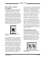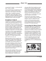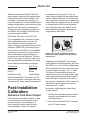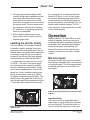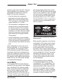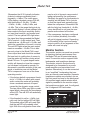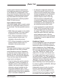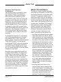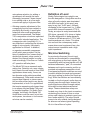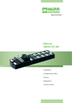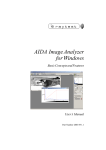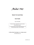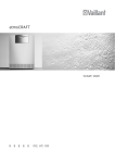
1
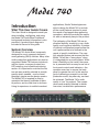
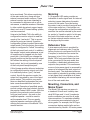
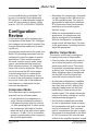
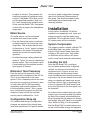
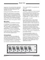
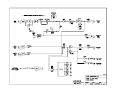
Model 740
Model 740 Audio Mixer
User Guide
Issue 3, May 2004
This User Guide is applicable for serial numbers:
M740-00151 and later
© 2004 by Studio Technologies, Inc., all rights reserved
www.studio-tech.com
50026-0504, Issue 3
This page intentionally left blank.
Model 740
Table of Contents
Introduction ................................................................... 5
System Features ........................................................... 6
Configuration Review .................................................... 8
Installation ..................................................................... 9
Post-Installation Calibration .......................................... 14
Operation ...................................................................... 15
Technical Notes ............................................................. 21
Specifications ................................................................ 24
Block Diagram
Model 740 User Guide
Studio Technologies, Inc.
Issue 3, May 2004
Page 3
Model 740
This page intentionally left blank.
Issue 3, May 2004
Page 4
Model 740 User Guide
Studio Technologies, Inc.
Model 740
Model 740
Introduction
What This User Guide Covers
This User Guide is designed to assist you
when installing, configuring, and using
the Model 740 Audio Mixer. Additional
background technical information is also
provided. A product block diagram is
included at the end of this guide.
System Overview
The Model 740 Audio Mixer is expressly
designed for use in compact electronicnews-gathering (ENG) vehicles. Many other
audio production applications can also be
supported. Model 740 features include six
mic/line inputs, a monaural output bus,
LED metering, and a flexible monitoring
section. It’s important to note that the feature set was carefully selected to provide
exactly what’s needed —and no more!
Keeping it simple was the design mantra.
The Model 740 is targeted for use by
operators that have a multitude of tasks
to perform, and too little time to do them.
Using its experience in mobile broadcast
applications, Studio Technologies was
able to design the Model 740 to include
all the crucial features required to meet
the needs of fast-paced news-gathering
operations, while still providing the operator with an extremely easy-to-use product.
The hallmarks of the Model 740 are application flexibility, simplicity in use, audio
quality, and long-term reliability. A number
of internal configuration jumpers allow the
unit’s performance to be tailored to the
needs of specific installations. The carefully selected feature set ensures that the
Model 740 will be a “team player” when
it’s integrated into an audio system. While
there’s flexibility on the inside, the operator is presented with an easy-to-use set of
front-panel controls and indicators—the
operator never has to access the back
panel to operate the unit. In this way the
goal of delivering successful on-air and
production audio, day-after-day, can best
be achieved. The Model 740’s audio
quality is “pro” throughout. The components were carefully selected to deliver
low-noise, low-distortion performance.
Model 740 Front Panel
Model 740 Back Panel
Model 740 User Guide
Studio Technologies, Inc.
Issue 3, May 2004
Page 5
Model 740
Reliability over the long haul was a Model
740 design criteria. To that end the unit’s
enclosure is made of steel, combining
strength with effective RF rejection. On
the inside, all components are mounted
on an FR4 (fiberglass-based) circuit
board assembly.
System Features
Mic/Line Inputs
Six input channels are provided for
connection to microphone or line-level
signals. The electronically balanced
circuitry is “ruggedized” for reliability
under tough operating conditions. The
low-noise, low-distortion, high-headroom
audio performance is what’s expected
of sophisticated “pro audio” equipment.
Features provided for each input channel
include an input sensitivity button, rotary
level control, and level status LED. For
ease of use, the rotary level control sets
both the gain of the input circuit and the
level being sent to the main audio bus.
For convenience the six input sensitivity
buttons, like all the Model 740’s operator
controls, are located on the front panel.
For operator assistance, the bicolor level
status LED provides signal present and
peak level indication.
Main Output
Signals from the six mic/line input channels combine to create a monaural signal
called the main output bus. A rotary control sets the overall level of the main bus.
An electronically balanced output circuit
is associated with the main output bus.
It provides a line-level signal capable of
driving balanced or unbalanced loads
of 600 ohms and greater. A studio-quality
audio compressor circuit is provided to
Issue 3, May 2004
Page 6
control the dynamic range of the main audio bus. An LED indicator lights whenever
the compressor circuit is actively controlling the signal. Far from a simple “clipper,”
the compressor circuit utilizes a sophisticated laser-trimmed voltage-controlled
amplifier (VCA) integrated circuit for quiet,
low-distortion operation. To help minimize
operator error, no compressor on/off switch
is provided on the Model 740’s front panel.
An internal 3-position configuration jumper
determines the compressor circuit’s operating mode. From the factory the jumper
is set so that the compressor’s operating threshold is 6 dB above the nominal
+4 dBu output level. This is an excellent
general-purpose setting for broadcast use
where voice signals are the primary audio
content.
To meet the needs of other installations,
a technician can change the jumper to
make the threshold 2 dB above the nominal +4 dBu. This could prove useful when
using the Model 740 with level-sensitive RF
transmission systems. For other applications a technician can set the jumper to
a third position which completely disables
the compressor function.
Monitor Section
The Model 740’s monitor section provides
a line-level monitor output, along with two
headphone outputs. Associated with the
monitor section is a rotary level control
and a 3-position source select switch. The
monitor output is compatible with a variety
of monitor amplifiers and amplified loudspeakers. For flexibility, two headphone
output jacks are provided, one on the
front panel and one on the back. Each
headphone jack is supported by an independent output circuit. A 3-position toggle
switch is used to select the audio source
Model 740 User Guide
Studio Technologies, Inc.
Model 740
to be monitored. This allows monitoring
of the main audio bus, along with two
external monaural audio sources. These
external monitor inputs are intended to
be connected to devices such as off-air,
microwave, or satellite receivers. Alternately, other mobile broadcast support equipment, such as a PC-based editing system,
can be connected.
Unique to the Model 740 is the ability to
configure the monitor output to meet the
needs of the “real world.” This is accomplished by using an internal 3-position
configuration jumper to select the monitor
output mode. From the factory the monitor
output is configured to “follow” the setting
of the front-panel level control. In addition,
the monitor output mutes whenever a pair
of headphones is plugged into the frontpanel jack. A technician can change the
jumper position so that the monitor output
still follows the setting of the front-panel
level control, but is not impacted by use
of the front-panel headphone jack.
A third jumper position allows a technician
to configure the monitor output such that
it is electrically before (“pre”) the level
control. As with the previous mode, the
output isn’t impacted by use of the headphone output. This mode is very useful
when an amplified loudspeaker that contains a user-accessible level control is
connected. Examples of amplified speakers that contain user level controls include
the popular Fostex® 6301-series. With the
jumper in the pre-level-control position,
only one level control—the one on the
amplified speaker—would be used to
set the speaker level. This can greatly
minimize operator confusion while still
utilizing the resources of the Model 740’s
monitor section.
Model 740 User Guide
Studio Technologies, Inc.
Metering
A 10-segment LED meter provides an
indication of audio-signal level. An internal
selection jumper determines the audio
source for the meter. From the factory
the meter is set to monitor the signal level
of the main audio bus. A technician can
change the configuration so that the meter
monitors the source selected by the monitor section’s 3-position switch. In this way
the level of the main audio bus, as well
as the two external monitor sources, can
be displayed by the meter.
Reference Tone
A sine-wave audio tone is provided for
alignment and reference use. From the
factory the tone is configured for 400 Hz.
If required, a technician can revise the
frequency to be 1 kHz. A button on the
Model 740’s front panel allows the tone
to be connected to the main audio bus.
In addition, a dedicated reference tone
output is also provided. This continuous
source of sine-wave signal is accessed by
means of a balanced line-level output on
the back panel. The dedicated reference
tone output is intended to provide a setup
or test signal that is available at all times,
and without interfering with normal operation of the main audio bus.
Mounting, Connectors, and
Mains Power
The Model 740 requires one space in
a standard 19-inch rack. Industry-standard XLR-type and ¼-inch 3-conductor
audio connectors are used for all audio
interconnections. To maximize reliability,
all connectors were selected to be premium grade. For example, the XLR-type
connectors feature metal shells and are
manufactured by Neutrik. AC mains power
Issue 3, May 2004
Page 7
Model 740
is connected directly to the Model 740
by way of a standard 3-pin detachable
IEC cord set; no external power supply is
used. AC mains power is factory configured for 100, 120, or 220/240 V, 50/60 Hz.
Configuration
Review
In this section you will be reviewing the
configuration of the Model 740. Configuration changes can be made if required. Any
changes should be made prior to installing the unit.
As previously mentioned in this guide, four
Model 740 operating parameters can be
configured to meet the needs of specific
applications. These include compressor mode, monitor output mode, meter
source, and reference tone frequency.
While simple to perform, all changes do
require the skill of a technician. This person must ensure that AC mains power
is disconnected prior to removing the
unit’s cover. Then the locations of one
or more of the configuration jumpers can
be moved. In the case of the reference
tone frequency, a calibration trim pot
must also be adjusted.
Compressor Mode
The compressor can be configured to
operate from one of three modes:
• From the factory the compressor is
set to have an operating threshold of
6 dB above the main output’s nominal
+4 dBu operating level. In other words,
the compressor will begin to function
when the level of the main output reaches about +10 dBu. This is an excellent
general purpose setting that is appropriate for most applications.
Issue 3, May 2004
Page 8
• Alternately, the compressor’s threshold
can be changed to be 2 dB above the
+4 dBu operating level. This may be
appropriate for applications where an
RF transmission chain places severe
restrictions on the audio signal’s
dynamic range.
• While not recommended for most
applications, the compressor can
also be configured to be disabled.
With this configuration, no dynamic
range control will take place. For most
on-air applications it’s unlikely that this
would be appropriate.
Monitor Output Mode
The monitor output can be configured
to operate from one of three modes:
• From the factory the monitor output is
set to follow the position of the frontpanel rotary level control. This mode
of operation is sometimes referred to
as being “post” the level control. In addition, plugging a pair of headphones
into the jack on the front panel will
cause the monitor output to mute.
• An alternate configuration is available
that makes the monitor output follow
the rotary level control’s setting. But
plugging headphones into the front
panel doesn’t cause muting of the
monitor output. This allows the monitor
output to be active, whether or not the
headphones are plugged in.
• A third mode is specifically provided
for use in applications where an amplified loudspeaker with built-in user level
control is connected. This “pre-levelcontrol” mode allows the user to select
the source to be monitored on the Model 740’s front panel. But only the level
control on the amplified speaker is used
Model 740 User Guide
Studio Technologies, Inc.
Model 740
to adjust its volume. This prevents the
confusing situation of having two level
controls—the Model 740’s level control
and the amplified speaker’s level control—both impacting the speaker level.
In this case the Model 740’s front-panel
control will only impact the headphone
output level.
Meter Source
The meter source can be configured
to operate from one of two modes:
• From the factory the meter is selected
to always monitor the level of the main
output bus. This ensures that the level
of the active or “on-air” output is always
displayed on the meter. Changing the
monitor source will not impact meter
operation.
• An alternate jumper setting allows the
meter to “follow” the source selected for
monitor output. This could prove useful
if level metering of the external monitor
input signals is desired.
Reference Tone Frequency
From the factory the frequency of the
reference tone is configured to be 400 Hz.
This is a nice alternative to the more
typical 1 kHz, a frequency which can soon
become very annoying to a listener’s ears.
In most cases 400 Hz will be perfectly
acceptable, and actually preferred. But
in those situations where 1 kHz is necessary, configuration jumpers can shift the
frequency range so that the oscillator
circuitry can be calibrated for 1 kHz.
Configuration Wrap-Up
If it is determined that any configuration
changes are required, they should now
have been performed. For specific details
Model 740 User Guide
Studio Technologies, Inc.
on how to make configuration changes,
refer to the Technical Notes section of
this guide. The details provided should
have made the process simple and
relatively painless.
Installation
In this section, the Model 740 will be
installed in an equipment rack. Input and
output connections will be made using
the Model 740’s multitude of jacks. Finally,
AC mains power will be connected.
System Components
The shipping carton contains a Model 740
Audio Mixer and user guide. Units destined for North America and Japan also
include an AC mains cord. Your dealer
or distributor will provide an AC mains
cord for non-North American destinations.
Locating the Unit
Now that the Model 740’s configuration has been reviewed and, if required,
revised, the unit can be mounted in an
equipment rack. Physical access and
viewing angles are the primary issues
to be considered when choosing a mounting location. By its very nature as an audio
mixer, an operator will need easy access
to all the controls. Also, a good sight line
to the 10-segment LED level meter, located on the right side of the front panel, can
be important.
As a device that contains high gain audio
stages, hum and noise pickup is possible
by way of the chassis and associated cabling. Locating the unit away from devices
that radiate strong AC fields is an excellent
idea. While not likely, it is also possible
that the Model 740’s toroidal power transformer could radiate energy into adjacent
Issue 3, May 2004
Page 9
Model 740
equipment. It is located at the far right side
of the unit, and may need to be physically
isolated from sensitive equipment such
videotape recorders.
740’s 3-pin IEC 320 C14-compatible inlet
connector.
During normal operation, access to the
Model 740’s back panel is not required.
However, there is one trim potentiometer
that may need to be adjusted prior to the
Model 740 going into service. This trim pot
sets the level of the reference tone direct
output. Please refer to the Post-Installation
Calibration section of this guide for details.
The Model 740 contains six input channels
that are compatible with microphone or
line-level sources. Each input uses a 3-pin
female XLR-type connector. Prepare the
mating connectors (males) so that pin 2
is signal high (+ or hot), pin 3 is low (– or
cold), and pin 1 is shield.
Mounting
The Model 740 is intended for mounting
in a standard 19-inch equipment rack,
requiring 1.75 vertical inches (one standard rack space). It weighs approximately
7.0 pounds (3.2 kg) and operates on
mains power of 100, 120, or 220/240 V,
50/60 Hz. The maximum operating power
is less than 24 watts. Four mounting
screws, two per side, are used to secure
the unit into the equipment rack.
Connections
The Model 740’s input and output connections are made using 3-pin XLR-type
male and female connectors and ¼-inch
3-conductor phone jacks. AC mains power
is connected by means of a detachable
cord set that is compatible with the Model
Mic/Line Inputs
It’s possible that some of the mic/line
inputs will be wired to an input/output
(I/O) panel located on the side or rear of
a broadcast vehicle. If this is the case, it’s
also nice to have one or two of the inputs
“multed” to connectors inside the vehicle.
This will allow the rapid connection of
microphone or line-level signals during
specialized situations. For example, during
inclement weather on-air talent may wish
to connect a microphone to the Model 740
from inside a vehicle.
To minimize potential problems, it is
recommended that microphone-level
signals connected to the mic/line inputs
not be wired by way of points on an audio
patch bay. It certainly can be done, but
the potential for intermittent connections,
especially in mobile applications, may
significantly increase.
Detail of back panel showing mic/line input connectors
Issue 3, May 2004
Page 10
Model 740 User Guide
Studio Technologies, Inc.
Model 740
Main Output—General
Information
The Model 740 contains one output that
is associated with the main audio bus.
It is electronically balanced, capacitor
coupled, and has a nominal level of
+4 dBu. The output circuitry is capable of
driving balanced or unbalanced loads of
600 ohms or greater. Note, however, that
as the load impedance approaches 600
ohms the output level will drop slightly. A
0.5 dB difference in output level can be
expected as the load impedance changes
from 10 k ohms to 600 ohms. This loading
situation also applies to the monitor and
reference tone direct outputs as well.
The output utilizes a 3-pin male XLR-type
connector for interconnection. Prepare the
mating connector (female) so that pin 2
is signal high (+ or hot), pin 3 is low (– or
cold), and pin 1 is shield. Whether this
output is wired via a patch bay will depend
on the specific installation. But at least
having a “mult” of the main output on a
patch point is probably a good idea.
While balanced operation is generally
preferred, unbalanced operation is not
a problem for the output circuitry. To connect to an unbalanced load prepare the
mating connector (female) so that pin 2 is
high (+ or hot), and both pins 1 and 3 are
shield. For optimal unbalanced operation,
it is important to connect both pins 1 and
3 together directly on the connector that
mates with the Model 740, not at the other
end of the cable.
External Monitor Inputs
Detail of back panel showing main output
connector
Note that the main output is intended only
for connection to devices located within
a broadcast vehicle or dedicated indoor
facility. While the output circuitry is robust
and sonically excellent, it’s not intended
for direct exposure to the extreme conditions that can occur in the nasty “outside
world.” This limitation is normally not an
issue as the main output will typically be
connected to the input of a distribution
amplifier. Should the main output need
to be connected directly to a vehicle’s I/O
panel, at a minimum a 1:1 isolation transformer should be placed in its path.
Model 740 User Guide
Studio Technologies, Inc.
Two external audio signals can be connected, allowing them to be monitored
independently of the activity on the main
audio bus. It is intended that the external
monitor inputs be connected to outputs
associated with devices such as off-air,
microwave, or satellite receivers, or other
specialized devices such as PC-based
video editing systems. The inputs are
Detail of back panel showing external monitor
input connectors
Issue 3, May 2004
Page 11
Model 740
monaural, electronically balanced, and
have a nominal level of +4 dBu. Audio
sources are connected to the external
monitor input’s 3-pin female XLR-type
connectors.
Prepare the mating connectors (males)
so that pin 2 is signal high (+ or hot),
pin 3 is low (– or cold), and pin 1 is shield.
With an unbalanced source connect pin 2
to high (+ or hot) and both pins 1 and 3
to shield. If connecting to an unbalanced
source in this manner results in hum or
noise, connect pin 2 to high (+ or hot) and
pin 3 to shield; leave pin 1 unterminated.
Monitor Output
The monitor output is designed to connect to an audio power amplifier associated with a monitor loudspeaker. In mobile
applications it’s also popular to use a
loudspeaker with an internal amplifier,
such as those from Fostex. The monitor
output is electronically balanced, capacitor coupled, line level, and can drive a balanced or unbalanced load of 600 ohms or
greater. The nominal output level has been
optimized to match the input sensitivity
typically found on audio amplifiers.
The monitor output utilizes a 3-pin male
XLR-type connector for interconnection.
Prepare the mating connector (female)
Detail of back panel showing monitor output
connector
Issue 3, May 2004
Page 12
so that pin 2 is signal high (+ or hot), pin
3 is low (– or cold), and pin 1 is shield. To
connect to an unbalanced load connect
pin 2 to high (+ or hot) and both pins 1
and 3 to shield. Whether or not this output
is wired via a patch bay will depend on the
specific installation.
Reference Tone Direct Output
Direct access to a continuous source of
sine-wave reference tone is provided by
means of a line-level output. As one of
the unique features of the Model 740, it
should definitely be utilized! This output
is intended to be connected to the audio input associated with a audio/video
switcher’s “bars and tone” position. For
maximum flexibility, it is recommended
that this signal be routed via a patch bay.
In this way it can be easily accessed for
other test and calibration purposes.
The reference tone direct output is
electronically balanced, has a nominal
+4 dBu level, and is accessible via a
3-pin male XLR-type connector. The
output circuitry is capable of driving a balanced or unbalanced load of 600 ohms
or greater. Prepare the mating connector
(female) so that pin 2 is signal high (+ or
hot), pin 3 is low (– or cold), and pin 1 is
shield. To connect to an unbalanced load
Detail of back panel showing reference tone
direct output connector, associated level trim
pot, and headphone output jack
Model 740 User Guide
Studio Technologies, Inc.
Model 740
connect pin 2 to high (+ or hot) and both
pins 1 and 3 to shield.
A trim potentiometer, accessible from the
back panel, is used to set the precise
output level of the reference tone direct
output. After an installation has been
completed it may be desirable to set the
trim pot to provide the required level. For
details please refer to the Post-Installation
Calibration section of this user guide.
Headphone Outputs
The Model 740 contains two headphone
outputs, one on the front panel and one
on the back panel. Both jacks are ¼-inch
3-conductor (“stereo”) tip-ring-sleeve type.
The jack on the front panel is intended to
allow an operator to plug in a pair of headphones as needed. No permanent connection should be made to this jack. The
headphone output jack on the back panel
is provided so that a remote headphone
output jack can be installed. This could
prove useful in cases where a headphone
jack might be desired on an I/O panel
located at a PC-based editing location,
small voice-over room, etc.
Separate output circuitry is used for the
front-panel and back-panel headphone
outputs. Depending on the configuration
of the Model 740’s monitor output, the
front-panel headphone output may cause
the monitor loudspeaker to mute. This
is not the case with the back-panel headphone output. A connector plugged into
the back-panel headphone jack will never
impact the monitor output.
Note that while the Model 740 is a singlechannel (monaural) device, the headphone outputs are configured to drive
stereo headphones. If possible, any
Model 740 User Guide
Studio Technologies, Inc.
plug used with either headphone output
should be a 3-conductor (stereo) type.
A 2-conductor plug will short the ring and
sleeve leads together, causing additional
loading to the headphone output circuit.
While not something that will cause a
reliability issue, it’s preferable if the rightchannel output is not shorted.
There may be cases where a remote
location may need to support a monaural
earpiece, such as a talent voice-over
position. In this case simply connect
only the tip and sleeve connections on
the 3-conductor plug used to mate with
the Model 740’s back-panel jack.
Connecting AC Mains Power
The Model 740 is factory configured to
operate from AC mains power of nominal 100, 120, or 220/240 V, 50/60 Hz. A
maximum of 24 watts of power is required.
Units shipped to locations within North
America are factory configured for 120 V
operation and are supplied with an internal 0.2 A, 5 x 20 mm time-lag fuse. Units
shipped to Japan are factory configured
for 100 V operation and use the same
0.2 A, 5 x 20 mm time-lag fuse. Units
configured for 220/240 V operation are
supplied with a 0.1 A, 5 x 20 mm time-lag
fuse.
Detail of back panel showing AC mains power
connector
Issue 3, May 2004
Page 13
Model 740
Before connecting the Model 740 to AC
mains power, determine the actual mains
voltage and confirm that the Model 740
has been configured appropriately. As
could be expected, an incompatible mains
voltage configuration could seriously damage the unit. Should it be necessary to
change the unit’s operating voltage contact Studio Technologies’ technical support personnel for details.
The Model 740 uses a 3-pin IEC 320
C14-compatible inlet connector to mate
with a detachable mains cord set. For
units shipped to North America and
Japan, a cord is supplied that has a NorthAmerican (NEMA 15L) standard plug on
one end and an IEC 320 C13-compatible
connector on the other. Units bound for
other destinations require that the appropriate cord set be obtained. The wire
colors in the mains cord must conform to
the internationally recognized color code
and should be terminated accordingly:
Connection
Wire Color
Neutral (N)
Live (L)
Earth/Ground (E)
Light Blue
Brown
Green/Yellow
Because the Model 740 contains no AC
mains on/off switch it will begin operation
as soon as AC mains power is connected.
Post-Installation
Calibration
Reference Tone Direct Output
If the reference tone direct output is used,
it’s important to confirm that its output
level is correct for the installation. In
most cases the output level will need
to be adjusted to match the precise
Issue 3, May 2004
Page 14
requirement of the system. This is because the load applied to the output may
well be different than the 100 k ohm load
that is applied at the factory. As previously
noted, while the output circuitry is capable
of driving loads of 600 ohms or greater,
the output level will drop slightly as the
load impedance changes, especially as
it approaches 600 ohms.
Detail of back panel highlighting reference
tone direct output connector and associated
level trim pot
Depending on the Model 740’s internal
configuration the tone frequency will be either 400 Hz or 1 kHz. A trim potentiometer
allows adjustment of the output level over
a range of approximately +3 to +7 dBu.
The trim pot is accessible by way of a
small access hole in the back panel, adjacent to the reference tone direct output’s
male XLR-type connector. At the factory
this output is loaded with 100 k ohms and
then the trim pot is adjusted to give an
output level of +4 dBu.
In practice, calibrating the output level
is quite simple:
1. Confirm that the reference tone direct
output is terminated with its normal
load impedance.
2. Ensure that the Model 740 is connected to AC mains power.
Model 740 User Guide
Studio Technologies, Inc.
Model 740
3. Using an appropriate adapter cable,
connect a high-input-impedance audio
level meter directly across the reference tone direct output. Ensure that
this meter connection does not remove
the normal load! The level meter must
be a precision device that’s intended
for audio use—a general-purpose voltmeter is not adequate!
For a great look it is recommended that
Brother® P-Touch ¼-inch (6 mm) labels
be created. Selecting tape material that
prints white text on a black background
works out perfectly for the Model 740. The
Brother label cassette number TX-3151,
white on black, is appropriate for use with
some of their printers.
4. While carefully observing the level
meter, adjust the trim pot to give the
desired output level.
Operation
Labeling the Unit for Clarity
Once the Model 740 has been installed,
installation-specific labeling of the front
panel may want to be performed. This additional clarity can greatly assist operators
in correctly using the unit. For example,
instead of the first mic/line input channel
having the factory-standard text INPUT
1, it could reflect its exact function, such
as TAPE 1. The unit’s front-panel graphics were specifically created to simplify
the task of adding custom labels. Under
each section heading text is a horizontal
green line, which, besides looking pretty
sharp, is intended to serve as a “guide”
for adding installation-specific labels. The
distance from the guide line to the top of
the unit was specifically designed to allow
¼-inch-high label material to fit correctly.
While the Model 740 Audio Mixer is quite
simple to operate, there are nuances in
its design that make a detailed discussion
worthwhile. We’ll start with the individual
sections that make up the Model 740,
then we’ll review how the sections work
together to become your audio “master
control.”
Mic/Line Inputs
Six identical input channels are provided,
each being compatible with a microphone
or line-level signal. The following provides
a detailed description of one of the mic/
line inputs:
Detail of front panel showing one mic/line input
channel
Detail of front panel showing installationspecific label
Model 740 User Guide
Studio Technologies, Inc.
Input Sensitivity
The input circuitry is compatible with a
wide range of signal levels and is protected from overload. The mic/line button is
used to select the sensitivity of the input.
Issue 3, May 2004
Page 15
Model 740
In the mic (out) position, the expected
nominal input level range is –55 to –35
dBu. In the line (in) position, a 43 dB pad
is inserted into the circuit, making the
expected nominal input level range –12 to
+8 dBu.
Status LED
A bicolor LED acts as a user-confidence
indication of the overall signal level in the
mic/line input channel’s circuitry. The LED
will light green as a signal present indicator, showing that the input signal, along
with the gain of the input preamplifier, is
at least 18 dB below the nominal internal
operating level. The LED will light red as
a peak signal indicator, showing that the
input signal, along with the gain of the
preamplifier, is within 6 dB of the circuitry’s
maximum level.
Level Control
The rotary control is used to adjust the
gain of the input section’s preamplifier
circuitry. In the fully counterclockwise
position the preamplifier gain is set to its
minimum, and full attenuation is achieved.
This means that no signal continues on to
the mixing circuitry that creates the main
audio bus. As the level control is rotated
in the clockwise direction the gain of the
preamplifier increases.
Master Output
The Model 740’s master output section
has one LED indicator and one rotary
control associated with it.
Master Level Control
One rotary control is used to set the overall level of the main audio bus. On the
front panel, note the graphic symbol and
the letter “U,” located at the approximately
Issue 3, May 2004
Page 16
“1-o’clock” rotational position. This indicates the correct setting for the master
output section to give unity gain, and
is the position where the control should
normally be set.
Detail of front panel showing master level
control, compressor active LED, and reference
tone on/off button
Reference Tone
A sine-wave tone can be connected to
the main audio bus, serving as a reference
signal for local and remote use. A pushbutton switch selects its status; when the
switch is in the on (in) position tone is connected. An LED indicator, which is located
directly below the switch, lights whenever
tone is being sent to the main bus. The
distinctive blue color of the LED is intended to clearly alert the user that tone
is active. The level of the tone generation
circuitry is adjusted at the factory to match
the Model 740’s internal operating level.
When the tone is connected to the main
audio bus, the master level control can be
adjusted to give a +4 dBu indication on
the level meter.
Compressor
A studio-quality compressor circuit is
associated with the main audio bus.
A yellow LED, located to the left of the
master level rotary control, lights whenever the compressor is controlling the
Model 740 User Guide
Studio Technologies, Inc.
Model 740
dynamic range of the main bus. The operating threshold of the compressor and
associated LED depends on how the
Model 740 has been configured:
• From the factory the compressor
threshold is set to be 6 dB over the
Model 740’s nominal operating level.
This correlates to a level on the main
output connector of +10 dBu.
with signals slightly higher than normal.
The red LED will light whenever the signal
level is in the “headroom” area. The ballistics of the meter is a cross between that
of a VU and a peak (PPM) meter. (We affectionately refer to it as a “PU” meter!)
The way the LEDs “move” in response to
signals should be comfortable for most
users to observe.
• The compressor’s configuration can
also be revised so that the threshold
is 2 dB over nominal. This correlates
to a nominal level on the main output
connector of +6 dBu. With this configuration the compressor may be active
quite frequently during typical Model
740 operation.
• A third configuration is also available
which serves to disable the compressor.
In this case dynamic range control will
never take place and the LED will never
light.
If the configuration is set to use one of
the two thresholds, i.e., the compressor
is not disabled, the compressor active
LED should prove useful. With the input
and master output level controls set correctly, the compressor active LED should
light only when peak signals are present.
For maximum audio fidelity during typical
Model 740 use, the LED should not light
or should light infrequently.
Level Meter
A 10-segment LED level meter displays
the level of the main output. And, depending on the Model 740’s internal configuration, it may also be able to display the
level of the two external monitor inputs.
The seven green LEDs will light in the
presence of signals in the normal operating range. The two yellow LEDs will light
Model 740 User Guide
Studio Technologies, Inc.
Detail of front panel highlighting 10-segment
LED level meter
Meter operation depends on the internal
configuration of the meter source mode.
A technician can select from one of two
choices: main output only or monitor
source select switch. From the factory
the meter is set to always display the level
of the main output. Alternately, the meter
can be configured to “follow” the source
selected for the monitor output. In this
way the level of either the main output,
or either of the external monitor inputs,
can be displayed.
While the meter is easy to interpret,
it’s somewhat different from one that
is marked with “VU” nomenclature. The
important thing to remember is that the
steps show level in dBu, rather than VU
units. So, for example, when the meter
step that is labeled “0” lights, it indicates
that 0 dBu is present on the main output
connector. It doesn’t indicate 0 VU!
Issue 3, May 2004
Page 17
Model 740
(Remember that 0 VU typically indicates
a device’s reference operating level—
frequently +4 dBm.) The seven green
LEDs display a dynamic range of 28 dB,
with thresholds of –24 dBu, –18 dBu,
–12 dBu, –8 dBu, –4 dBu, 0 dBu, and
+4 dBu. This is the range that typical signals should display if correct settings have
been made to the input sensitivity switches, input level controls, and master level
control. The two yellow LEDs light when
the signal level has exceeded the Model
740’s nominal +4 dBu output level. Their
thresholds are +8 dBu and +12 dBu, well
within the capabilities of the unit’s circuitry.
The red LED lights when the main output
meets or exceeds +18 dBu. This is dangerously close to the Model 740’s maximum output level and should be avoided.
But now back to reality when it comes to
how the meter will function during actual
Model 740 use. To a great degree meter
activity will depend on how the compressor has been configured to operate. As
discussed in previous sections of this user
guide, a technician can set the Model
740’s compressor from one of the three
operating modes:
• If the factory-default compressor threshold of +10 dBu is in effect with normal
audio content the meter will probably
show a moderate amount of impact
caused by the dynamic range control.
The two yellow LEDs may light on peak
signal levels, along with the compressor
active LED. The red LED will essentially
never light.
• If the threshold is set for +6 dBu, typically only the first yellow LED will light.
The second yellow LED will rarely light.
And the red LED will probably never
light. With this configuration there often
Issue 3, May 2004
Page 18
may be a lot of dynamic range control
being performed by the compressor.
Obviously the goal is for the operator to
carefully set the Model 740’s controls
so that the signal level generally stays
below the compressor’s threshold. But
with the fairly low threshold of +6 dBu,
it may be difficult to not have the compressor active almost all the time.
• If the compressor has been configured
not to function (disabled), the meter
will get its biggest workout. Depending
on the setting of the input and master
output controls, all ten segments of the
meter will come into play.
Monitor Section
The monitor section can assist an operator
in obtaining the best performance from
the Model 740 and its associated equipment. The monitor section supports both
loudspeaker and headphone devices.
The monitor output is line level and is
designed to be connected to an audio
power amplifier and associated loudspeaker. Alternatively, it can be connected
to an “amplified” loudspeaker that contains an internal power amplifier. Separate
headphone outputs are provided, one on
the front panel and one on the back panel.
A 3-position toggle switch selects which
signal is presented to the monitor output,
the headphone outputs, and, if configured,
the 10-segment LED level meter.
Detail of front panel showing monitor section
Model 740 User Guide
Studio Technologies, Inc.
Model 740
A rotary control sets the output level of
the headphone outputs and, depending
on the Model 740’s configuration, may
also control the level of the monitor output
loudspeaker. Understanding and becoming comfortable with using the monitor
section is important in obtaining optimal
Model 740 performance.
Source Selection Switch
A 3-position toggle switch is used to select
which one of the three audio sources is to
be monitored. The three possible sources
are:
• MAIN: When the handle is in the middle
position the Model 740’s main output
is selected as the monitor source.
• EXT 1: When the handle is in the up
position external monitor input 1 is
selected as the monitor source.
• EXT 2: When the handle is in the down
position external monitor input 2 is
selected as the monitor source.
Level Control
The rotary control is always used to adjust
the output level of the front- and backpanel headphone outputs. Depending
on how the monitor output mode is configured, the rotary control may also control the level of a connected loudspeaker.
There are three ways that the monitor
output can be configured:
• From the factory the monitor output is
configured to “follow” the position of
the level control on the front panel. In
addition, the monitor output is muted
whenever a plug is inserted into the
front-panel headphone jack. In this
mode the front-panel control is used to
adjust the level of both the loudspeaker
and, if connected, headphones.
Model 740 User Guide
Studio Technologies, Inc.
• An alternate configuration allows the
level of the monitor output to be controlled by the front-panel rotary control.
However, plugging into the front-panel
headphone jack will not cause the
monitor output to mute. In this way
both the monitor loudspeaker and
connected headphones can be active
simultaneously. The level of both the
loudspeaker and the headphones will
be controlled by the rotary control.
• A third configuration mode takes the
Model 740’s front-panel level control
out of the picture vis-à-vis the monitor output. The rotary control will still
adjust the level of the front- and backpanel headphone jacks. With this
mode the level control on the amplified
loudspeaker is used to adjust the loudspeaker level.
Headphone Outputs
The two headphone outputs are designed
to work well with virtually any of the contemporary medium- and high-impedance
stereo headphones. Sony headphones
were used during the design of the Model
740; their high sensitivity made them go
“way loud”! (While a bit “bright” in the
high-end for our taste, their comfort and
fine design make them a good choice for
use with the Model 740.) The headphone
outputs are also compatible with monaural
“ear buds” that are commonly used for
IFB feeds to reporters and other “on-air”
talent. Selecting an ear bud impedance of
2 k ohms or greater is preferable, although
almost any will work.
Independent output circuitry is used for
the front- and back-panel headphone
outputs. Thus ’phones plugged into the
front-panel jack will not impact a connection made to the back-panel jack. The
Issue 3, May 2004
Page 19
Model 740
outputs are compatible with stereo headphones but really provide a 2-channel
monaural audio signal. Technically, one
output driver circuit connects, by way of
two series resistors, to both the tip (“left”)
and the ring (“right”) jack connections. In
this way the Model 740’s monaural main
output (and mono external monitor inputs)
will correctly drive the left and right channels on a pair of stereo headphones. The
series resistors ensure that correct operation will take place should headphones or
ear buds with 2-conductor (mono) plugs
be used.
Warning: Protect your ears! The
Model 740 is capable of driving headphones to extremely high sound pressure levels. Hearing experts advise
against continuous extended play,
especially at high levels. Polka music
has been found to be especially dangerous, so please be careful.
1. Set the tone button to the on (in)
position. This will cause the blue LED
to light and a precision-level sine-wave
tone to be connected to the main audio
bus. (The factory-default frequency for
the tone is 400 Hz tone but a configuration change allows 1 kHz.)
2. Select main as the monitor source.
(This is only necessary if the meter
configuration has been set to “follow”
the monitor source.)
3. Adjust the master level control so that
the meter’s +4 dBu LED just begins
to light. The main audio bus is now
set for unity gain.
4. The procedure has now been completed. Return the tone button to the
off (out) position.
Now that we’ve reviewed all the sections
that comprise the Model 740, it’s time to
actually use the unit. The following paragraphs provide suggestions regarding
how to best use the Model 740.
Signal Present/Peak LEDs
Bicolor status LEDs are associated with
each of the six mic/line inputs. Simply
stated, lighting green is fine, lighting red
is bad. So with a channel’s mic/line switch
and level control set correctly only the
green color should light. Signal peaks
may cause an occasional red “flash,” but
sustained red lighting indicates that audio
performance is being compromised.
Setting the Overall Operating Level
The master output level control allows
the overall gain structure of the main audio
bus to be set. Correctly setting this control
ensures that maximum audio quality will
be achieved. In most cases simply setting the control to the unity gain position
is appropriate; the unity gain position is
clearly marked with a triangle or “carrot”
and a “U” on the front panel. If you are a
fanatic for accuracy you may want set the
level control “precisely” using the following procedure:
Compressor Active LED
The compressor active LED is located directly to the left of the master level control.
It will light with a yellow color whenever
dynamic range control is taking place. If
the compressor has been configured not
to operate (disabled) then obviously the
LED will never light. If the compressor
is enabled, typical operation should find
the LED lighting on occasion, or even
frequently on signal peaks. But the LED
should never light continuously. If this is
the case the input level controls should
Practical Operating Tips
Issue 3, May 2004
Page 20
Model 740 User Guide
Studio Technologies, Inc.
Model 740
be adjusted to reduce the amount of signal
being sent to the main audio bus. Also, the
position of the master level control should
be checked to ensure that it is set correctly.
In most cases it should be set to the reference position, marked “U” for unity gain.
Technical Notes
Configuration Changes
Warning: A competent technician
is required to perform any configuration review or changes. The cover
of the Model 740 must be removed
to access the configuration jumpers.
This exposes the technician to a
potential shock hazard. Only after AC
mains power has been disconnected
and the mains cord removed from the
back of the Model 740, should the
cover be removed. Four screws, two
on each side of the chassis, are used
to secure the cover.
Compressor Configuration
The compressor is configured to operate from one of three modes. A shorting
“jumper” is used to select which mode
is active. From the factory the jumper is
placed across the two pins in the position
labeled +10 dBu. This sets the compressor threshold to be 6 dB above the Model
740’s +4 dBu nominal output level. Moving
the jumper to the +6 dBu position sets the
compressor threshold to be 2 dB above the
+4 dBu nominal output level. To disable
compressor operation place the jumper on
the pins labeled OFF. Finding the compressor configuration location is not difficult.
When viewed with the cover off and starting
from the front panel, it is located directly
behind the master level control.
Model 740 User Guide
Studio Technologies, Inc.
Meter Source Configuration
The 10-segment LED meter is configured to operate from one of two modes.
A shorting “jumper” is used to select the
active mode. From the factory the jumper
is placed across the pins labeled MAIN.
This sets the meter to always monitor the
main audio bus. Moving the jumper to the
MONITOR location sets the meter to “follow” the source selected by the monitor
section. Finding the meter source configuration location is not difficult. When viewed
with the cover off and starting from the
front panel, it is located behind the monitor source select switch.
Monitor Output Configuration
The monitor section’s line-level output
is configured to operate from one of three
modes. A shorting “jumper” is used to
set the active mode. From the factory the
jumper is placed across the pins labeled
POST MUTE. This configures the output
so that it is after (“post”) the level control
as well as muting when headphones are
plugged into the front panel headphone
jack. Moving the jumper to the POST
location sets the monitor to again be after
(“post”) the level control but plugging
into the front-panel headphone jack will
not cause the output to mute. Placing the
jumper on the pins labeled PRE sets the
monitor output to be electrically before
(“pre”) the level control. In this mode plugging into the front-panel headphone jack
does not impact the monitor output. Finding the monitor output configuration location is not difficult. When viewed with the
cover off and starting from the front panel,
it is located behind the monitor source
select switch.
Issue 3, May 2004
Page 21
Model 740
Reference Tone Frequency
Configuration
Two shorting jumpers are used to select
the frequency range of the reference
tone oscillator. A trim potentiometer is
then used to set the frequency to the
exact desired value. From the factory the
frequency of the reference tone is set to
be 400 Hz. This is accomplished by first
setting the jumpers to the two locations
that are labeled 400HZ. Then the trim pot
is adjusted to give a 400 Hz signal when
measured between the common and tone
test points. Like the jumper locations,
the trim pot and tests points are located
on the Model 740’s printed circuit board
assembly.
To change the frequency to 1 kHz simply
start by moving the jumpers to the positions labeled 1KHZ. Then, using a frequency counter, adjust the trim pot labeled
TONE FREQ to give 1 kHz on the test
point labeled TONE. Finding the reference
tone frequency configuration location is
not difficult. When viewed with the cover
off, it is located adjacent to the back-panel
headphone output jack.
Be careful not to adjust the trim pot that
is labeled TONE LEVEL. This adjusts the
output level of the oscillator to give precisely –2 dBu to the main audio bus when
the front-panel tone button is enabled.
Should this pot have to be readjusted the
procedure is quite simple: measure across
the COM and TONE test points and adjust
the trim pot to give –2 dBu. The measurement equipment must have a high input
impedance (>2 k ohms) so as not to load
the oscillator’s output.
Issue 3, May 2004
Page 22
Model 740 Limitations
The Model 740 was carefully designed
with simplicity of operation in mind. Only
the required features and functions were
included. The goal was reliable audio
performance with little risk that operator
confusion or errors would occur. Protecting the audio signals associated with live
news “shots” was foremost on the list of
requirements. The Model 740’s design
team spent lots of time reviewing what
could be included, then were told by
field personnel to take everything out
that wasn’t absolutely required! Here’s
a review of some of the features that
weren’t included and the reason why:
• Including microphone phantom power
would have been nice. But it’s almost
never needed for live news broadcasts.
(An external phantom supply can easily
be used for those rare occasions.) And
providing true 48 volt phantom, along
with individual on/off switches, is the
only technically strong way to do it. So
from the start this feature would have
added six more pushbutton switches.
And while generating 48 volts isn’t difficult, it does add cost and generates
additional heat in the enclosure. Other
mixers don’t worry about supplying
the “real deal,” instead providing 12
volts, or some nonstandard value such
as 15 volts. While often acceptable,
these voltages can’t be depended
upon to power all phantom-powered
microphones.
• Including high-pass filters on the
mic/line inputs was a possibility. But
in the “heat of battle” it’s unlikely that
an operator will have the time to enable
them. Also, this requires another six
front-panel switches for the on/off
functions. If wind noise is an issue,
Model 740 User Guide
Studio Technologies, Inc.
Model 740
microphone selection (or adding a
windscreen) will resolve the issue.
Alternately, personnel “down stream”
in an editing suite or at a live audio
console can apply a high-pass filter.
• Allowing operator adjustment of the
compressor function was certainly a
possibility. But frankly, it would guarantee that often audio performance
would be compromised. The Model
740’s compressor circuit was optimized
for the unit’s intended application. The
compression ratio (nominally 5:1) is
very effective in controlling the dynamic
range of voice signals, the primary
application for the unit. In addition,
no operator-accessible compressor
on/off switch was provided. If at the
time of installation the “powers that be”
decide that dynamic range control is
desired, the internal jumper is configured accordingly. From then on “hands
off” operation will take place.
• The Model 740 has a monaural audio
mixing bus. Certainly not a sexy choice,
but it meets the real needs of most ENG
applications where rarely, if ever, are
two discrete audio paths transmitted
simultaneously. Other audio mixers that
support dual-channel or stereo operation are often either hard to use, poorly
implemented, or both. For applications
that require separate audio buses there
is no reason why two Model 740s can’t
be installed together. (Or Studio Technologies’ technically rich Model 750
Audio Mixer could be used. In just two
rack spaces, two stereo or four monaural mixes can be created.)
Model 740 User Guide
Studio Technologies, Inc.
Definition of Level
Studio Technologies has opted to use
the dBu designation. Using dBm was fine
when all audio outputs were terminated
with 600 ohm loads. In this way it was
easy to say that “0 dB” was 1 milliwatt
dissipated in the known load (i.e., 0 dBm
across 600 ohms will measure 0.775 V).
Today, an output is rarely terminated with
600 ohms; generally 10 k ohms or higher.
The dBu designation is better because
it refers to dB referenced to 0.775 V, with
load impedance not a factor. This takes
into account the contemporary audio
scene where most equipment has a low
output source impedance and a high
input impedance.
Mic/Line Switching
As previously discussed, the six input
circuits can be selected for compatibility
with microphone or line-level signals. For
compatibility with line-level signals a 43 dB
balanced attenuator (“pad”) is connected
between each input connector and its associated microphone preamplifier circuit.
Front-panel pushbutton switches are used
to select whether the pads are bypassed
(mic input setting) or active (line input setting). While the switches are conveniently
located on the front panel, audio does not
actually pass through them. Instead, the
audio signals are routed through sealed,
bifurcated contact electromechanical
relays. These subminiature relays are
located very close to the input connectors,
minimizing the chance of hum or noise
pickup and helping to maintain good common-mode rejection. The relays should
prove to be very reliable, being designed
for telecom use where typical operating
life is in the millions of cycles.
Issue 3, May 2004
Page 23
Model 740
Specifications
General Audio Parameters:
External Monitor Inputs: 2, monaural
Frequency Response: 20 Hz-20 kHz, ±0.5 dB,
mic/line in to main out
Type: electronically balanced, direct-coupled,
compatible with balanced or unbalanced signals
Distortion (THD+N): 0.03%, measured at 1 kHz,
+4 dBu, mic/line in to main out
Impedance: 24 k ohms, nominal
S/N Ratio: 74 dB, referenced to +4 dBu, mic/line
in to main out, 22 Hz-22 kHz
Mic/Line Inputs: 6
Input Sensitivity: switch selectable for microphone or live-level signals; 43 dB line input “pad”
implemented using sealed bifurcated contact
telecom relays
Operating Level Range: mic input position: –78
to –8 dBu; line position: –35 to +35 dBu. Range
specified to give +4 dBu on main output, master
level control set to unity gain position.
Type: electronically balanced
Impedance: mic position 2 k ohms, line position
15k ohms
Common Mode Rejection Ratio: 70 dB @ 60 Hz,
69 dB @ 40 kHz (typical), mic position, ref +4 dBu
on main out
Common Mode Rejection Ratio: 90 dB @ 60 Hz,
70 dB @ 86 kHz, typical
Nominal Level: +4 dBu
Monitor Output:
Type: electronically balanced, capacitor-coupled,
intended to drive balanced or unbalanced loads of
600 ohms or greater
Source Impedance: 50 ohms, nominal
Nominal Level: +6 dBu, with monitor level control
@ 100%, mode selected to be post level control
(no headphone mute)
Maximum Level: +26 dBu into 10 k ohms,
+25 dBu into 600 ohms
Signal Source: configurable, choices are 1) post
monitor level control with headphone muting
(factory default), 2) post monitor level control,
3) pre monitor level control
Status LED: bicolor, displays signal present
and peak
Headphone Outputs:
Compressor:
Configuration: separate output driver circuitry
for front and back headphone output connections
Type: single-knee, VCA-controlled
Slope: 5:1
Threshold: configurable, choices are 1) 6 dB over
nominal (+10 dBu on main output, factory default),
2) 2 dB over nominal (+6 dBu on main out),
3) disabled
Source: same as selected for monitor output
Type: monaural source configured to drive stereo
headphones through of 100 ohm resistors
Compatibility: intended for connection to headphones with impedance of 100 ohms or greater
Maximum Voltage: 5.5 Vpp, 100 ohm load
Attack Time: 2 mSec
Reference Tone:
Release Time: 100 mSec
Frequency and Wave Form: 400 Hz nominal,
sine wave (technician can revise to 1 kHz)
Status LED: compressor active
Main Output:
Type: electronically balanced, capacitor-coupled,
intended to drive balanced or unbalanced loads of
600 ohms or greater
Source Impedance: 50 ohms, nominal
Nominal Level: +4 dBu
Direct Output Level: +4 dBu, nominal, adjustable
over –1/+3 dB range
Direct Output Type: electronically balanced,
capacitor-coupled, intended to drive balanced
or unbalanced loads of 600 ohms or greater
Direct Output Source Impedance: 100 ohms,
nominal
Maximum Level: +26 dBu into 10 k ohms,
+25 dBu into 600 ohms
Issue 3, May 2004
Page 24
Model 740 User Guide
Studio Technologies, Inc.
Model 740
Metering:
Type: 10-segment LED, modified VU ballistics
Source: configurable, choices are 1) display level
of main output bus (factory default), 2) source
selected for monitor output
Connectors:
Mic/Line and External Monitor Inputs: 3-pin
XLR-type, female
Main, Reference Tone Direct and Monitor
Outputs: 3-pin XLR-type, male
Headphones: ¼-inch 3-conductor phone jacks
AC Mains: 3-blade, IEC 320 C14-compatible
(mates with IEC 320 C13)
AC Mains Requirement: 100, 120, or 220/240 V,
±10%, factory configured; 50/60 Hz; 0.2 A
maximum
Mains Fusing: 1
Type: 5x20 mm, time-lag
Rating: 0.2 A for 100 V and 120V AC mains,
0.1 A for 220/240 V AC mains
Dimensions (Overall):
19.00 inches wide (48.3 cm)
1.72 inches high (8.9 cm)
7.2 inches deep (18.3 cm)
Mounting: one standard rack space
Weight: 7.0 pounds (3.2 kg)
Specifications and information contained in this
User Guide subject to change without notice.
Model 740 User Guide
Studio Technologies, Inc.
Issue 3, May 2004
Page 25
Model 740
This page intentionally left blank.
Issue 3, May 2004
Page 26
Model 740 User Guide
Studio Technologies, Inc.