1
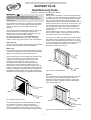
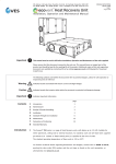
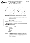
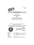
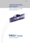
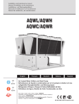
A
VES Andover Ltd Eagle Close Chandlers Ford Ind. Est Eastleigh Hampshire SO53 4NF
Tel: 08702 404340 Fax: 08702 404550 E-mail: [email protected] Web: www.ves.co.uk
VES Ref: ID 618
Issue D
JULY 2006
ECOVENT PLUS
Heat Recovery Units
Installation, Operation and Maintenance Manual
Face & bypass
damper
number and the unit type, as found on the unit nameplate.
After this period, we would be unable to accept any claim for
damaged or missing goods.
Filter (Supply)
Extract fan
!
IMPORTANT
Handles, lids, housings and coil connections must not be
used as lifting points
Filter (Extract)
When moving the unit, handle with care and in such a
manner as to avoid damaging the external finish as this may
reduce the ability to resist corrosion. Units are to be rigged
and lifted using spreaders, taking into account the weight of
the unit, and lifting gear should be arranged so as not to
bear on the casework.
For further details, refer to the unit outline drawing.
3
Plate heat
exchanger
Controls (optional)
LPHW Section
Supply fan
Fig.1 Typical unit layout
Where a unit is installed so that a failure of components
could result in injury to personnel, precautions should be
taken to prevent such an injury. If the unit is installed where
there is a reasonable possibility of persons or objects
coming into contact with the impeller, a guard should be
fitted.
EHB Section
!
IMPORTANT
This manual must be read in full before Installation,
Operation and Maintenance of the units supplied
Contents
1
2
3
4
5
6
7
8
Introduction
Receipt of Goods/Handling
Installation
Set-up
Wiring
Maintenance
Warranty
Declaration of Conformity
1
Introduction
Installation
The entire system must be considered for safety purposes
and it is the responsibility of the installer to ensure that all of
the equipment is installed in compliance with the
manufacturer’s recommendations, with due regard to the
current HEALTH AND SAFETY AT WORK ACT and conforms
to all relevant statutory regulations.
page
1
1
1
3
3
6
7
8
It is the installer’s responsibility to ensure that access panels
are not obstructed in any way and safe working access for
maintenance must be provided in line with Health and Safety
and Building Regulations.
For optimum unit performance, careful consideration must be
paid to the location of the unit in relation to the ductwork and
associated items; placing the unit directly adjacent to a bend
in ductwork will impede airflow and reduce performance.
Consideration must also be given by the installer for
adequate illumination of the unit location in order for safe
maintenance.
The Ecovent Plus series is a range of heat recovery units,
direct and belt driven, with duties up to 2m³/s. Suitable for
plant-room, ceiling void and external locations, each unit will
have been supplied with either no pre-wiring, pre-wired to an
external isolator or with fitted control panel as specified at
the time of order. The standard operating temperature of
these units is –20 to +35°C.
Sectional (tubular framed) units should be assembled using
self-adhesive rubber tape at the joints prior to assembly so
as to prevent air leakage; replace with similar if damaged.
For further technical details regarding dimensions and
weights, contact VES on 08702 404340, quoting the sales
order (SO) number and the unit type as found on the unit
nameplate or visit www.ves.co.uk.
Electric Heater Batteries
Supply to the heater should be 1ph or 3ph with separate
neutrals; confirmation of this can be found on the unit
nameplate. Cables should be of silicone rubber, fibreglass or
of a similar high temperature insulated type and be installed
to current I.E.E. Regulations, ensuring a sufficient earth
connection to the terminal provided. Care should be taken
not to overstrain the terminal pillars as this may permanently
damage the elements.
The heater is fitted with a manual reset high temperature cutout with normally closed (NC) terminals. The cut-out is set to
break if the duct temperature rises above 130°C and must be
connected in series with the main contactor coil circuit if the
heater is to be isolated in the event of overheating.
2
IMPORTANT
!
Only experienced fitters should undertake this work. Take
necessary safety precautions when working in elevated positions
Receipt of Goods/Handling
Immediately upon receipt of goods, check for possible
damage in transit paying particular attention to fan impellers,
motor, flexible connections, coil connections and unit casing.
Prior to installation please check to ensure smooth rotation
of the impeller after transit. Also check to ensure that any
ancillary items are included. These will normally be supplied
fitted or, in the case of small items, taped to the unit.
In the event of any damage having occurred or if any item is
found to be missing, it is essential to inform VES Andover
Ltd. within 7 working days of delivery quoting sales order
The electrical supply must be isolated before attempting to
reset the manual cut-out.
1-
A
VES Andover Ltd Eagle Close Chandlers Ford Ind. Est Eastleigh Hampshire SO53 4NF
Tel: 08702 404340 Fax: 08702 404550 E-mail: [email protected] Web: www.ves.co.uk
ECOVENT PLUS
Heat Recovery Units
Installation, Operation and Maintenance Manual
Steam Coils
Steam coils are suitable for use with saturated steam up
to 100psi. The pipe work must be so arranged to provide
adequate drain lines with a suitable strainer and steam
trap. All steam and drain lines should be lagged. The
supply should be taken from the top of the steam main, to
avoid the introduction of moisture or air into the coil. The
pipe shall be arranged so that it does not interfere with
the coil expansion. Where steam coils are fitted it is
essential that a time delay is installed in the fan starter
control circuit.
The fan shall be kept running for at least two minutes
after the steam supply to the coils has been shut off, so
that residual heat of the coil is dissipated.
IMPORTANT
!
In order to prevent overheating within the unit and
consequent damage to integral components, a 2-5
minute fan run on timer should be incorporated into the
control circuit.
The elements are tested prior to dispatch and are within a
tolerance of 7.5W. In the event that elements should be
found to be faulty they can be easily removed and
replaced.
To remove the electric heater battery, take out the fixings
from the element tray and slide the assembly free.
Elements that are stored in damp conditions may need
drying to attain correct insulation readings.
For further technical details contact VES Customer
Services Department, quoting the sales order (SO)
number and the unit type as found on the unit nameplate.
If the pipe run is unduly long and prone to water logging,
it should be properly trapped, just before the coil. If the
steam is from a high pressure steam main, it is essential
to have a working pressure relief valve on the low side to
ensure that dangerous overheating of the air and
excessive pressure cannot occur.
Drain Pan Trap
Where a drain pan is fitted, please refer to trapping detail
manual: ‘VES Ref: ID665’ ‘Drain Trap Installation’.
Water Coils
Low Pressure Hot water (LPHW) coils should have an air
vent and drain plug located on the pipe work immediately
adjacent to the AHU: they are not fitted to the coil.
Flow
The air vent should be at the highest point, with the drain
at the lowest. When the coil is at a high point of the
system it should be regularly vented so as to avoid
potential air locks resulting in a fall off of duty.
It is important that water coils are protected against
damage from extreme weather conditions during the
winter season. If the water is allowed to freeze in the coil
system, damage may occur potentially bursting pipes and
resulting in emergency problems. This can be prevented
by fitting a frost thermostat at the unit inlet and ensuring
that boilers run continuously in low ambient temperatures.
Airflow
Return
Fig.3 Steam Coil Connections
DX Coils
DX and Condenser Coils must be connected to systems
in accordance with accepted refrigeration codes of
practice and if fitted upstream to steam or water coils,
care must be taken to ensure that the air temperature
does not drop below 0oC.
Return
Airflow
Flow
Liquid
Fig.2 Water Coil Connections
Airflow
It is recommended that a check be made as to whether
any treatment is required to the water supply for
prevention of corrosion and scaling of the equipment.
Information regarding the necessary action to be taken
can be obtained from the relevant Water Supply Authority.
Suction
Drain
Fig.4 DX and Condenser Coil Connections
2-
VES Andover Ltd Eagle Close Chandlers Ford Ind. Est Eastleigh Hampshire SO53 4NF
Tel: 08702 404340 Fax: 08702 404550 E-mail: [email protected] Web: www.ves.co.uk
A
ECOVENT PLUS
Heat Recovery Units
Installation, Operation and Maintenance Manual
IMPORTANT
!
Should it be necessary to remove any slide-in component,
ensure that these are secured into position once reinstalled
to prevent untreated air bypass
5
!
IMPORTANT
Electrical supply must be fully isolated before attempting to
affect any work on this unit
Where provided, flanges and spigots should not be used to
support the ductwork and used solely as a means of
ductwork connection. Further consideration should be given
to the unit’s position and secured into place as appropriate.
This is especially important with external mounting as the
wind and elements may effect the overall stability of the unit.
4
All electrical connections to any unit must be carried out in
accordance with the current edition of the
I.E.E REGULATIONS and only competent Electricians should
be allowed to affect any electrical work to our units.
IMPORTANT
!
Do not connect any unit to an electrical supply voltage
outside of that indicated on the motor name plate
Set-up
Motor and electrical details must be checked prior to
connection to mains supply. All motor information can be
found on the unit data sheet, supplied attached to the unit.
Units with direct drive fans should be subject to a check that
the impeller blades are not damaged and spin freely.
The following wiring diagrams are a guide to installing the
standard fan, motor and actuator options. If in any doubt, or
for special versions of the units, consult the wiring diagram in
your document pack or contact our customer services
department on 08702 404340, quoting the sales order (SO)
number and unit type as found on the unit name plate.
Units with belt driven fans should be checked to ensure that
the transit bolts and spacer are removed from fan and motor
frames. These are used to protect the anti-vibration mounts
and flexible connections during delivery, and must be
removed for these items to be effective.
!
IMPORTANT
It is essential that all electrical connections are properly made
VES ECOVENTPLUS units contain two centrifugal fans
acting as supply and extract through a plate heat exchanger.
A local isolator must be fitted and mains cables should be
suitably sized see fig.7 and terminated as shown on the
appropriate wiring diagram see fig.8,9 & 10. Ensure that
suitable strain relief is fitted to the mains supply as
appropriate. Note: 2 speed motors are dual wound.
Ensure correct pulley alignment as indicated in fig.5 below.
To check the tension of the drive belt apply a force
perpendicular to the centre of the belt span sufficient to
deflect the belt 16mm for every metre of span length, as
indicated in fig.6. The force required to deflect the belt
should be from 0.5 to 0.8kg. Do not over tighten the belts as
this will damage the bearings in both fan and motor.
After the unit has been positioned, re-check that the impeller
is smooth running as this may have moved during transit.
8
wrong
8
wrong
Wiring
Please refer to VES for information on single phase motors
or 2 speed dual wound motors.
9
correct
Fig.5 Pully alignment
Fig.6 Belt tension
3-
A
5
VES Andover Ltd Eagle Close Chandlers Ford Ind. Est Eastleigh Hampshire SO53 4NF
Tel: 08702 404340 Fax: 08702 404550 E-mail: [email protected] Web: www.ves.co.uk
ECOVENT PLUS
Heat Recovery Units
Installation, Operation and Maintenance Manual
Wiring continued
Pre-wired sectional units will require reconnection of numbered wires to the isolator/control panel.
Please refer to the isolator/control panel wiring diagram for details
Fig.7 Electrical Details
Model
ECOPLUS
ECO113
VES Fan
Ref.
AL321
Motor Input
(W)
310
FLC*
(A)
1.26
FanSpeed
(rpm)
1945
230V 1Ph 50Hz
ECO213
AL321
350
1.45
1945
230V 1Ph 50Hz
ECO214
AL441
460
2.10
1280
230V 1Ph 50Hz
ECO215
AL541
675
3.15
1380
230V 1Ph 50Hz
ECO226
GZ641
1310
5.70
860
230V 1Ph 50Hz
ECO326
GZ641
1150
5.10
1380
230V 1Ph 50Hz
ECO327
GZ741
1650
7.20
1380
230V 1Ph 50Hz
ECO427
GZ741
1650
7.20
1380
230V 1Ph 50Hz
Model
ECOPLUS
ECO541-1500
Motor Size
(kW)
1.1
ECO541-1600
Supply Voltage
2.8
SC** Fan Speed
(A)
(rpm)
12.32
1500
400V 3Ph 50Hz
1.5
3.6
20.52
1600
400V 3Ph 50Hz
ECO541-1700
1.5
3.6
20.52
1700
400V 3Ph 50Hz
ECO541-1800
1.5
3.6
20.52
1800
400V 3Ph 50Hz
ECO541-1900
2.2
5.3
25.44
1900
400V 3Ph 50Hz
ECO541-2000
2.2
5.3
25.44
2000
400V 3Ph 50Hz
ECO642-1200
1.5
3.6
20.52
1200
400V 3Ph 50Hz
ECO642-1300
1.5
3.6
20.52
1300
400V 3Ph 50Hz
ECO642-1400
2.2
5.3
25.44
1400
400V 3Ph 50Hz
ECO642-1500
2.2
5.3
25.44
1500
400V 3Ph 50Hz
ECO642-1600
2.2
5.3
25.44
1600
400V 3Ph 50Hz
ECO743-1300
2.2
5.3
25.44
1300
400V 3Ph 50Hz
ECO743-1400
3.0
6.8
31.28
1400
400V 3Ph 50Hz
ECO743-1500
3.0
6.8
31.28
1500
400V 3Ph 50Hz
ECO743-1600
3.0
6.8
31.28
1600
400V 3Ph 50Hz
ECO743-1700
4.0
9.2
55.20
1700
400V 3Ph 50Hz
ECO844-1100
3.0
6.8
31.28
1100
400V 3Ph 50Hz
ECO844-1200
3.0
6.8
31.28
1200
400V 3Ph 50Hz
ECO844-1300
3.0
6.8
31.28
1300
400V 3Ph 50Hz
ECO844-1400
4.0
9.2
55.20
1400
400V 3Ph 50Hz
ECO844-1500
4.0
9.2
55.20
1500
400V 3Ph 50Hz
FLC* (A)
FLC* Full Load Current
SC** Nominal Starting Current
4-
Supply Voltage
A
ECOVENT PLUS
Heat Recovery Units
Installation, Operation and Maintenance Manual
Wiring continued
Standard fan wiring arrangement
Standard actuator wiring arrangement
Fig.8 230v 1Ph 50Hz
Fig.10
capacitor
N
0
1
Open/Close
Control
Direction of
rotation
E
L
Unit:
113 & 213 Only
N
2
blue
1
NM230A/NM24A
Damper Actuator
To isolate from the
main power supply,
the system must
incorporate a
device which
disconnects the
phase conductors.
E
Unit:
214, 215, 226
326, 327, 427
3
brown
1
N
white
green/yellow
blue
brown
black
blue
brown
L
230V 1Ph 50Hz
24V 1 Ph 50Hz
0
capacitor
not used
5
VES Andover Ltd Eagle Close Chandlers Ford Ind. Est Eastleigh Hampshire SO53 4NF
Tel: 08702 404340 Fax: 08702 404550 E-mail: [email protected] Web: www.ves.co.uk
L1
(+)
(-)
Standard motor wiring arrangement
Fig.9 400v 3Ph 50Hz
U1
W1
U1
V1
W1
V1
W2
U2
V2
W2
U2
V2
U1
V1
W1
U1
V1
W1
L1
L2
L3
E
L1
L2
L3
E
Star Connection
For motors up to & including 4kW
Note: A trial connection of the three phase (3Ph) supply should be made to check that the fan rotates in the correct
direction as indicated on the fan. If the rotation is incorrect, interchange any two phases of the incoming supply at the
terminal block.
5-
A
6
VES Andover Ltd Eagle Close Chandlers Ford Ind. Est Eastleigh Hampshire SO53 4NF
Tel: 08702 404340 Fax: 08702 404550 E-mail: [email protected] Web: www.ves.co.uk
ECOVENT PLUS
Heat Recovery Units
Installation, Operation and Maintenance Manual
Maintenance
IMPORTANT
!
Before attempting to carry out any maintenance work,
investigative or repair work on our units, the unit MUST BE
COMPLETELY ISOLATED from its electrical supply
Ensure a minimum of two minutes after electrical
disconnection before removing access panels. This will
allow any moving parts to come to a rest
The face and bypass damper should be afforded some
protection by the unit filtration. If required, clean blades,
cogs and frames, and lubricate with a PTFE aerosol
lubricant or equivalent.
Plate heat recovery units have no moving parts, therefore
only minimal maintenance is required. Periodically inspect
heat exchange matrix for any debris, dust or dirt build up.
Frequent contamination might be as a result of poor filtration
and should be investigated. A reduction in filtration quality
can be caused by factors such as sagging of filter media,
due to excess moisture or rips and tears in the material.
If found to be contaminated, foreign matter should be
removed by one of the following methods;
Superficial dust or debris can be removed from the surface
of the heat exchange matrix by gently brushing. Loosened
debris can then be vacuumed from the surface of the matrix.
or flushed through with warm water.
Stubborn deposits can be removed by using a low pressure
washer with an approved detergent solution. The solution
temperature should not exceed 50°C. When using any
pressure device care must be taken not to damage the heat
exchange matrix. Under NO circumstances should the heat
exchanger be steam cleaned.
Should a full service be required it may be necessary to
disassemble the unit casework to gain access to the heat
exchanger.
In general, these units require little maintenance. All fan
and motor bearings are supplied fully greased and
lubricated. In the unlikely event of component failure, spares
are available from stock at VES Andover Ltd.
WARNING
!
When used in conjunction with an inverter for speed control,
a minimum of 5 minutes should be given to allow for the
capacitors to discharge before starting work after
disconnection from the power source
!
IMPORTANT
Before attempting to carry out any work on our units, all
accompanying documentation including warning labels on
the unit must be referenced
Three Monthly Check
The belt drive should be thoroughly checked. Belts are
subject to fatigue and will stretch over a period of time.
Again, within normal operating conditions, belts tend to
stretch in the first few days of running; inspection of belts at
this early stage is advised. After this initial period, regular 3
monthly checks should be made. If belts are found to be
loose or worn, retighten or replace as necessary. Refer to
fig.6 for the recommended tension.
Do not mix belts. If two or more belts are used make sure
that all are replaced at the same time. Excess wear on the
side of belts indicates misalignment of the pulleys and
should be rectified at once see fig.5.
Filters should be inspected regularly. If they are found to be
heavily soiled or damaged they should be replaced
immediately.
The general operation of the unit should be inspected,
paticularly for noise from bearings, motors and fans. An
irregular noise could signify that unit failure is iminent.
Annual Checks
Ecovent Plus units are supplied with either unpainted
galvanized sheet steel or powder coat paint finishes. Check
all painted items to ensure that they have not deteriorated.
Repaint as necessary. Paint can be supplied upon request.
Checks should be carried out for missing fasteners
!
IMPORTANT
Should it be necessary to remove any slide-in component
ensure that these are secured into position once reinstalled.
It is critical that after any maintenance work has been
conducted that all components removed/replaced be refitted
correctly by a competent engineer
WEEE Directive
At the end of their useful life the packaging and product
should be disposed of via a suitable recycling centre.
Do not dispose of with normal household waste.
Do not burn.
Six Monthly Check
As above, plus:
Check for dust build-up in the system, especially around the
impeller. Remove the dust if necessary. Failure to do this
periodically could lead to a loss of performance or cause the
fan to become out of balance, ultimately leading to bearing
failure.
Coils should be inspected every six months to ascertain if
any foreign matter has accumulated between the fins and
that the coil connections are free from any leaks.
Should any matter be found, the coils should be cleaned
using a soft brush and mild solution of commercial
detergent. If heavily contaminated, a steam lance may be
used.
When enquiring after, or ordering spares contact VES
Spares Department, quoting the sales order (SO)
number and unit type as found on the unit nameplate.
Telephone
Fax
A
08702 40 43 40
08702 40 45 50
B
PLEASE ENSURE THAT THIS DOCUMENT IS
PASSED ON TO THE END USER.
We reserve the right to alter the specifcation without notice
!
IMPORTANT
Care should be taken so as not to damage or distort the fins
during this cleaning process.
©VES Andover Ltd. 2006
No part of this publication may be photocopied or otherwise reproduced without the prior permission in writing of VES Andover Ltd.
6-
A
7
VES Andover Ltd Eagle Close Chandlers Ford Ind. Est Eastleigh Hampshire SO53 4NF
Tel: 08702 404340 Fax: 08702 404550 E-mail: [email protected] Web: www.ves.co.uk
ECOVENT PLUS
Heat Recovery Units
Installation, Operation and Maintenance Manual
Warranty
Extended Warranties
All VES Andover Products come with a one year guarantee from date of dispatch, which covers parts and labor.
You can now extend this with the following options:
Option 1.
FREE extended Warranty
We can offer you a maintenance agreement that keeps this equipment in tip-top condition.
If you take out this agreement, we will extend the warranty free of charge for up to 5 years, providing the regular maintenance agreement remains in place.
Option 2.
12-24 Month Extended Warranty
12-24 months from the date of dispatch. This can be covered at a cost of just 3% of order value. (minimum charge £50.00).
Option 3.
12-36 Month Extended Warranty
12-36 months from date of dispatch. For this cover, the charge is 6% of order value (Minimum charge £80)
Please State which option you require when you place your order. A transferable certificate will then be issued to you.
Please note, this offer excludes condensing units. We would be happy to quote you for these separately.
Register for separate spares reminders and get a 10% discount
Register for this free service and we will automatically send you a regular reminder detailing the consumable spares for this
unit, together with their current list prices.
You will then be entitled to a 10% discount off any spares.
To arrange any of these options.
or
Phone:
Email:
023 8046 1150
[email protected]
Stating the sales order and reference number from the unit.
7-
A
VES Andover Ltd Eagle Close Chandlers Ford Ind. Est Eastleigh Hampshire SO53 4NF
Tel: 08702 404340 Fax: 08702 404550 E-mail: [email protected] Web: www.ves.co.uk
ECOVENT PLUS
Heat Recovery Units
Installation, Operation and Maintenance Manual
Declaration of Conformity
Date:
8th November 2004
Product:
ECOVENTPLUS Heat Recovery Unit
Type:
ECO
Manufacturer:
VES Andover Limited
The product above is produced in accordance with EC Council Directives:
98/37/EC (Machinery Directive)
89/336/EEC and amendment 92/31/EEC (Electromagnetic Compatibility Directive)
73/223/EEC and amendment 93/68/EEC (Low Voltage Directive)
The European Harmonised Standards applied are:
BS EN ISO 12100, EN 294, EN61000, EN 60204-1
The National Standards applied in particular are :
BS 848 Part 1
Basis of Self attestation:
Quality Assurance to ISO 9001-2000, BSI Reg. Firm Cert. No. Q5375
Signature of Manufacturer:
Position of Signatory:
Technical Director
8-