1
SLM R12+
Owner’s manual
R9010171
R5976654/05
27/01/2005
Barco nv Events
Noordlaan 5, B-8520 Kuurne
Phone: +32 56.36.89.70
Fax: +32 56.36.88.24
E-mail: [email protected]
Visit us at the web: www.barco.com
Printed in Belgium
Changes
Barco provides this manual ’as is’ without warranty of any kind, either expressed or implied, including but not limited to the implied warranties or merchantability and fitness for a particular purpose. Barco may make improvements and/or changes to the product(s) and/or the
program(s) described in this publication at any time without notice.
This publication could contain technical inaccuracies or typographical errors. Changes are periodically made to the information in this
publication; these changes are incorporated in new editions of this publication.
Copyright ©
All rights reserved. No part of this document may be copied, reproduced or translated. It shall not otherwise be recorded, transmitted or
stored in a retrieval system without the prior written consent of Barco.
Federal Communications Commission (FCC Statement)
This equipment has been tested and found to comply with the limits for a class A digital device, pursuant to Part 15 of the FCC rules.
These limits are designed to provide reasonable protection against harmful interference when the equipment is operated in a commercial
environment. This equipment generates, uses, and can radiate radio frequency energy and, if not installed and used in accordance with
the instruction manual, may cause harmful interference to radio communications. Operation of this equipment in a residential area may
cause harmful interference, in which case the user will be responsible for correcting any interference.
Trademarks
Brand and product names mentioned in this manual may be trademarks, registered trademarks or copyrights of their respective holders.
All brand and product names mentioned in this manual serve as comments or examples and are not to be understood as advertising for
the products or their manufactures.
Table of contents
TABLE OF CONTENTS
1. Safety Instructions . . . . . . . . . . . . . . . . . . . . . . . . . . . . . . . . . . . . . . . . . . . . . . . . . . . . . . . . . . . . . . . . . . . . . . . . . . . . . . . . . . . . . . . . . . . . . . . . . . 5
1.1
1.2
1.3
Warnings. . . . . . . . . . . . . . . . . . . . . . . . . . . . . . . . . . . . . . . . . . . . . . . . . . . . . . . . . . . . . . . . . . . . . . . . . . . . . . . . . . . . . . . . . . . . . . . . . . . . . . . . . . . . . . . . . . . . . . . . . . . . . . . 5
FCC statement . . . . . . . . . . . . . . . . . . . . . . . . . . . . . . . . . . . . . . . . . . . . . . . . . . . . . . . . . . . . . . . . . . . . . . . . . . . . . . . . . . . . . . . . . . . . . . . . . . . . . . . . . . . . . . . . . . . . . . . . 5
Note. . . . . . . . . . . . . . . . . . . . . . . . . . . . . . . . . . . . . . . . . . . . . . . . . . . . . . . . . . . . . . . . . . . . . . . . . . . . . . . . . . . . . . . . . . . . . . . . . . . . . . . . . . . . . . . . . . . . . . . . . . . . . . . . . . . . 5
2. Packaging and Dimensions . . . . . . . . . . . . . . . . . . . . . . . . . . . . . . . . . . . . . . . . . . . . . . . . . . . . . . . . . . . . . . . . . . . . . . . . . . . . . . . . . . . . . . . 7
2.1
2.2
2.3
2.4
2.5
Projector Packaging. . . . . . . . . . . . . . . . . . . . . . . . . . . . . . . . . . . . . . . . . . . . . . . . . . . . . . . . . . . . . . . . . . . . . . . . . . . . . . . . . . . . . . . . . . . . . . . . . . . . . . . . . . . . . . . . . . .
Box Content . . . . . . . . . . . . . . . . . . . . . . . . . . . . . . . . . . . . . . . . . . . . . . . . . . . . . . . . . . . . . . . . . . . . . . . . . . . . . . . . . . . . . . . . . . . . . . . . . . . . . . . . . . . . . . . . . . . . . . . . . . .
Lamp Packaging . . . . . . . . . . . . . . . . . . . . . . . . . . . . . . . . . . . . . . . . . . . . . . . . . . . . . . . . . . . . . . . . . . . . . . . . . . . . . . . . . . . . . . . . . . . . . . . . . . . . . . . . . . . . . . . . . . . . . .
Lens Packaging . . . . . . . . . . . . . . . . . . . . . . . . . . . . . . . . . . . . . . . . . . . . . . . . . . . . . . . . . . . . . . . . . . . . . . . . . . . . . . . . . . . . . . . . . . . . . . . . . . . . . . . . . . . . . . . . . . . . . . .
Projector Dimensions . . . . . . . . . . . . . . . . . . . . . . . . . . . . . . . . . . . . . . . . . . . . . . . . . . . . . . . . . . . . . . . . . . . . . . . . . . . . . . . . . . . . . . . . . . . . . . . . . . . . . . . . . . . . . . . . .
2.5.1 Projector Dimensions. . . . . . . . . . . . . . . . . . . . . . . . . . . . . . . . . . . . . . . . . . . . . . . . . . . . . . . . . . . . . . . . . . . . . . . . . . . . . . . . . . . . . . . . . . . . . . . . . . . . . . . . . . .
2.5.2 Projector Dimensions (Inclusive Dust Filters) . . . . . . . . . . . . . . . . . . . . . . . . . . . . . . . . . . . . . . . . . . . . . . . . . . . . . . . . . . . . . . . . . . . . . . . . . . . . . . . . .
7
7
7
8
8
8
9
3. Installation Guidelines. . . . . . . . . . . . . . . . . . . . . . . . . . . . . . . . . . . . . . . . . . . . . . . . . . . . . . . . . . . . . . . . . . . . . . . . . . . . . . . . . . . . . . . . . . . . . 11
3.1
3.2
3.3
3.4
3.5
General . . . . . . . . . . . . . . . . . . . . . . . . . . . . . . . . . . . . . . . . . . . . . . . . . . . . . . . . . . . . . . . . . . . . . . . . . . . . . . . . . . . . . . . . . . . . . . . . . . . . . . . . . . . . . . . . . . . . . . . . . . . . . . . 11
Configuration . . . . . . . . . . . . . . . . . . . . . . . . . . . . . . . . . . . . . . . . . . . . . . . . . . . . . . . . . . . . . . . . . . . . . . . . . . . . . . . . . . . . . . . . . . . . . . . . . . . . . . . . . . . . . . . . . . . . . . . . . 12
Safety Area around projector . . . . . . . . . . . . . . . . . . . . . . . . . . . . . . . . . . . . . . . . . . . . . . . . . . . . . . . . . . . . . . . . . . . . . . . . . . . . . . . . . . . . . . . . . . . . . . . . . . . . . . . . 14
Projector tilting. . . . . . . . . . . . . . . . . . . . . . . . . . . . . . . . . . . . . . . . . . . . . . . . . . . . . . . . . . . . . . . . . . . . . . . . . . . . . . . . . . . . . . . . . . . . . . . . . . . . . . . . . . . . . . . . . . . . . . . . 16
Mounting the projection lamp . . . . . . . . . . . . . . . . . . . . . . . . . . . . . . . . . . . . . . . . . . . . . . . . . . . . . . . . . . . . . . . . . . . . . . . . . . . . . . . . . . . . . . . . . . . . . . . . . . . . . . . . 16
3.5.1 Access to the Lamp Unit.. . . . . . . . . . . . . . . . . . . . . . . . . . . . . . . . . . . . . . . . . . . . . . . . . . . . . . . . . . . . . . . . . . . . . . . . . . . . . . . . . . . . . . . . . . . . . . . . . . . . . . 17
3.5.2 Installation of the new Lamp Unit.. . . . . . . . . . . . . . . . . . . . . . . . . . . . . . . . . . . . . . . . . . . . . . . . . . . . . . . . . . . . . . . . . . . . . . . . . . . . . . . . . . . . . . . . . . . . . 17
3.5.3 Reinstalling the Side Panel. . . . . . . . . . . . . . . . . . . . . . . . . . . . . . . . . . . . . . . . . . . . . . . . . . . . . . . . . . . . . . . . . . . . . . . . . . . . . . . . . . . . . . . . . . . . . . . . . . . . 19
3.6 Realignment of the lamp in its reflector. . . . . . . . . . . . . . . . . . . . . . . . . . . . . . . . . . . . . . . . . . . . . . . . . . . . . . . . . . . . . . . . . . . . . . . . . . . . . . . . . . . . . . . . . . . . . . 20
3.7 Lenses . . . . . . . . . . . . . . . . . . . . . . . . . . . . . . . . . . . . . . . . . . . . . . . . . . . . . . . . . . . . . . . . . . . . . . . . . . . . . . . . . . . . . . . . . . . . . . . . . . . . . . . . . . . . . . . . . . . . . . . . . . . . . . . . 23
3.7.1 Lenses . . . . . . . . . . . . . . . . . . . . . . . . . . . . . . . . . . . . . . . . . . . . . . . . . . . . . . . . . . . . . . . . . . . . . . . . . . . . . . . . . . . . . . . . . . . . . . . . . . . . . . . . . . . . . . . . . . . . . . . . . 23
3.7.2 Lens selection . . . . . . . . . . . . . . . . . . . . . . . . . . . . . . . . . . . . . . . . . . . . . . . . . . . . . . . . . . . . . . . . . . . . . . . . . . . . . . . . . . . . . . . . . . . . . . . . . . . . . . . . . . . . . . . . . 23
3.7.3 Lens formulas. . . . . . . . . . . . . . . . . . . . . . . . . . . . . . . . . . . . . . . . . . . . . . . . . . . . . . . . . . . . . . . . . . . . . . . . . . . . . . . . . . . . . . . . . . . . . . . . . . . . . . . . . . . . . . . . . . 23
3.7.4 Lens Installation . . . . . . . . . . . . . . . . . . . . . . . . . . . . . . . . . . . . . . . . . . . . . . . . . . . . . . . . . . . . . . . . . . . . . . . . . . . . . . . . . . . . . . . . . . . . . . . . . . . . . . . . . . . . . . . 24
3.7.5 Cleaning the lens . . . . . . . . . . . . . . . . . . . . . . . . . . . . . . . . . . . . . . . . . . . . . . . . . . . . . . . . . . . . . . . . . . . . . . . . . . . . . . . . . . . . . . . . . . . . . . . . . . . . . . . . . . . . . . 25
3.8 Battery Installation in the RCU. . . . . . . . . . . . . . . . . . . . . . . . . . . . . . . . . . . . . . . . . . . . . . . . . . . . . . . . . . . . . . . . . . . . . . . . . . . . . . . . . . . . . . . . . . . . . . . . . . . . . . . 25
3.9 Stacking Projectors. . . . . . . . . . . . . . . . . . . . . . . . . . . . . . . . . . . . . . . . . . . . . . . . . . . . . . . . . . . . . . . . . . . . . . . . . . . . . . . . . . . . . . . . . . . . . . . . . . . . . . . . . . . . . . . . . . . 27
3.10 Rigging points and Accessories . . . . . . . . . . . . . . . . . . . . . . . . . . . . . . . . . . . . . . . . . . . . . . . . . . . . . . . . . . . . . . . . . . . . . . . . . . . . . . . . . . . . . . . . . . . . . . . . . . . . . 30
4. Connections. . . . . . . . . . . . . . . . . . . . . . . . . . . . . . . . . . . . . . . . . . . . . . . . . . . . . . . . . . . . . . . . . . . . . . . . . . . . . . . . . . . . . . . . . . . . . . . . . . . . . . . . . 33
4.1
4.2
4.3
4.4
4.5
Power connection . . . . . . . . . . . . . . . . . . . . . . . . . . . . . . . . . . . . . . . . . . . . . . . . . . . . . . . . . . . . . . . . . . . . . . . . . . . . . . . . . . . . . . . . . . . . . . . . . . . . . . . . . . . . . . . . . . . . 33
Switching on . . . . . . . . . . . . . . . . . . . . . . . . . . . . . . . . . . . . . . . . . . . . . . . . . . . . . . . . . . . . . . . . . . . . . . . . . . . . . . . . . . . . . . . . . . . . . . . . . . . . . . . . . . . . . . . . . . . . . . . . . . 33
Switching to standby . . . . . . . . . . . . . . . . . . . . . . . . . . . . . . . . . . . . . . . . . . . . . . . . . . . . . . . . . . . . . . . . . . . . . . . . . . . . . . . . . . . . . . . . . . . . . . . . . . . . . . . . . . . . . . . . . 35
Switching off . . . . . . . . . . . . . . . . . . . . . . . . . . . . . . . . . . . . . . . . . . . . . . . . . . . . . . . . . . . . . . . . . . . . . . . . . . . . . . . . . . . . . . . . . . . . . . . . . . . . . . . . . . . . . . . . . . . . . . . . . . 35
Input Source Connections . . . . . . . . . . . . . . . . . . . . . . . . . . . . . . . . . . . . . . . . . . . . . . . . . . . . . . . . . . . . . . . . . . . . . . . . . . . . . . . . . . . . . . . . . . . . . . . . . . . . . . . . . . . 35
4.5.1 Input Facilities . . . . . . . . . . . . . . . . . . . . . . . . . . . . . . . . . . . . . . . . . . . . . . . . . . . . . . . . . . . . . . . . . . . . . . . . . . . . . . . . . . . . . . . . . . . . . . . . . . . . . . . . . . . . . . . . . 35
4.5.2 Inputs via RCVDS05. . . . . . . . . . . . . . . . . . . . . . . . . . . . . . . . . . . . . . . . . . . . . . . . . . . . . . . . . . . . . . . . . . . . . . . . . . . . . . . . . . . . . . . . . . . . . . . . . . . . . . . . . . . 35
4.5.3 Input module insertion . . . . . . . . . . . . . . . . . . . . . . . . . . . . . . . . . . . . . . . . . . . . . . . . . . . . . . . . . . . . . . . . . . . . . . . . . . . . . . . . . . . . . . . . . . . . . . . . . . . . . . . . . 36
4.5.4 Fixed slot (slot 1 & 2) . . . . . . . . . . . . . . . . . . . . . . . . . . . . . . . . . . . . . . . . . . . . . . . . . . . . . . . . . . . . . . . . . . . . . . . . . . . . . . . . . . . . . . . . . . . . . . . . . . . . . . . . . . 37
4.5.5 Serial Digital Input (slot 3 & 4) . . . . . . . . . . . . . . . . . . . . . . . . . . . . . . . . . . . . . . . . . . . . . . . . . . . . . . . . . . . . . . . . . . . . . . . . . . . . . . . . . . . . . . . . . . . . . . . . 38
4.5.6 HD SDI Digital input (slot 3 & 4). . . . . . . . . . . . . . . . . . . . . . . . . . . . . . . . . . . . . . . . . . . . . . . . . . . . . . . . . . . . . . . . . . . . . . . . . . . . . . . . . . . . . . . . . . . . . . . 39
4.5.7 Digital Video Decoder Input . . . . . . . . . . . . . . . . . . . . . . . . . . . . . . . . . . . . . . . . . . . . . . . . . . . . . . . . . . . . . . . . . . . . . . . . . . . . . . . . . . . . . . . . . . . . . . . . . . . 40
4.6 Communication Connections . . . . . . . . . . . . . . . . . . . . . . . . . . . . . . . . . . . . . . . . . . . . . . . . . . . . . . . . . . . . . . . . . . . . . . . . . . . . . . . . . . . . . . . . . . . . . . . . . . . . . . . . 42
4.6.1 RS232 (RS422) Connection. . . . . . . . . . . . . . . . . . . . . . . . . . . . . . . . . . . . . . . . . . . . . . . . . . . . . . . . . . . . . . . . . . . . . . . . . . . . . . . . . . . . . . . . . . . . . . . . . . . 42
4.6.2 Linked System . . . . . . . . . . . . . . . . . . . . . . . . . . . . . . . . . . . . . . . . . . . . . . . . . . . . . . . . . . . . . . . . . . . . . . . . . . . . . . . . . . . . . . . . . . . . . . . . . . . . . . . . . . . . . . . . . 42
4.6.3 Communication with peripherals . . . . . . . . . . . . . . . . . . . . . . . . . . . . . . . . . . . . . . . . . . . . . . . . . . . . . . . . . . . . . . . . . . . . . . . . . . . . . . . . . . . . . . . . . . . . . . 45
4.6.4 Network connection. . . . . . . . . . . . . . . . . . . . . . . . . . . . . . . . . . . . . . . . . . . . . . . . . . . . . . . . . . . . . . . . . . . . . . . . . . . . . . . . . . . . . . . . . . . . . . . . . . . . . . . . . . . . 45
5. Getting Started. . . . . . . . . . . . . . . . . . . . . . . . . . . . . . . . . . . . . . . . . . . . . . . . . . . . . . . . . . . . . . . . . . . . . . . . . . . . . . . . . . . . . . . . . . . . . . . . . . . . . . 47
5.1
5.2
5.3
5.4
5.5
5.6
5.7
RCU & Local keypad . . . . . . . . . . . . . . . . . . . . . . . . . . . . . . . . . . . . . . . . . . . . . . . . . . . . . . . . . . . . . . . . . . . . . . . . . . . . . . . . . . . . . . . . . . . . . . . . . . . . . . . . . . . . . . . . . 47
Terminology overview . . . . . . . . . . . . . . . . . . . . . . . . . . . . . . . . . . . . . . . . . . . . . . . . . . . . . . . . . . . . . . . . . . . . . . . . . . . . . . . . . . . . . . . . . . . . . . . . . . . . . . . . . . . . . . . . 47
Operating the projector. . . . . . . . . . . . . . . . . . . . . . . . . . . . . . . . . . . . . . . . . . . . . . . . . . . . . . . . . . . . . . . . . . . . . . . . . . . . . . . . . . . . . . . . . . . . . . . . . . . . . . . . . . . . . . . 48
5.3.1 Switching on . . . . . . . . . . . . . . . . . . . . . . . . . . . . . . . . . . . . . . . . . . . . . . . . . . . . . . . . . . . . . . . . . . . . . . . . . . . . . . . . . . . . . . . . . . . . . . . . . . . . . . . . . . . . . . . . . . . 48
5.3.2 Switching to standby. . . . . . . . . . . . . . . . . . . . . . . . . . . . . . . . . . . . . . . . . . . . . . . . . . . . . . . . . . . . . . . . . . . . . . . . . . . . . . . . . . . . . . . . . . . . . . . . . . . . . . . . . . . 49
5.3.3 Switching off . . . . . . . . . . . . . . . . . . . . . . . . . . . . . . . . . . . . . . . . . . . . . . . . . . . . . . . . . . . . . . . . . . . . . . . . . . . . . . . . . . . . . . . . . . . . . . . . . . . . . . . . . . . . . . . . . . . 49
5.3.4 Temperature error DMD . . . . . . . . . . . . . . . . . . . . . . . . . . . . . . . . . . . . . . . . . . . . . . . . . . . . . . . . . . . . . . . . . . . . . . . . . . . . . . . . . . . . . . . . . . . . . . . . . . . . . . . 49
Quick Set Up Adjustments . . . . . . . . . . . . . . . . . . . . . . . . . . . . . . . . . . . . . . . . . . . . . . . . . . . . . . . . . . . . . . . . . . . . . . . . . . . . . . . . . . . . . . . . . . . . . . . . . . . . . . . . . . . 50
5.4.1 Quick Language Change . . . . . . . . . . . . . . . . . . . . . . . . . . . . . . . . . . . . . . . . . . . . . . . . . . . . . . . . . . . . . . . . . . . . . . . . . . . . . . . . . . . . . . . . . . . . . . . . . . . . . . 50
5.4.2 Quick Lens Adjustment . . . . . . . . . . . . . . . . . . . . . . . . . . . . . . . . . . . . . . . . . . . . . . . . . . . . . . . . . . . . . . . . . . . . . . . . . . . . . . . . . . . . . . . . . . . . . . . . . . . . . . . . 51
5.4.3 Quick On Screen Color change . . . . . . . . . . . . . . . . . . . . . . . . . . . . . . . . . . . . . . . . . . . . . . . . . . . . . . . . . . . . . . . . . . . . . . . . . . . . . . . . . . . . . . . . . . . . . . . 52
Using the RCU . . . . . . . . . . . . . . . . . . . . . . . . . . . . . . . . . . . . . . . . . . . . . . . . . . . . . . . . . . . . . . . . . . . . . . . . . . . . . . . . . . . . . . . . . . . . . . . . . . . . . . . . . . . . . . . . . . . . . . . 53
Projector Address . . . . . . . . . . . . . . . . . . . . . . . . . . . . . . . . . . . . . . . . . . . . . . . . . . . . . . . . . . . . . . . . . . . . . . . . . . . . . . . . . . . . . . . . . . . . . . . . . . . . . . . . . . . . . . . . . . . . 55
5.6.1 Controlling the projector . . . . . . . . . . . . . . . . . . . . . . . . . . . . . . . . . . . . . . . . . . . . . . . . . . . . . . . . . . . . . . . . . . . . . . . . . . . . . . . . . . . . . . . . . . . . . . . . . . . . . . . 55
5.6.2 Displaying and Programming addresses . . . . . . . . . . . . . . . . . . . . . . . . . . . . . . . . . . . . . . . . . . . . . . . . . . . . . . . . . . . . . . . . . . . . . . . . . . . . . . . . . . . . . 56
Controlling the Projector . . . . . . . . . . . . . . . . . . . . . . . . . . . . . . . . . . . . . . . . . . . . . . . . . . . . . . . . . . . . . . . . . . . . . . . . . . . . . . . . . . . . . . . . . . . . . . . . . . . . . . . . . . . . . 56
6. Start up of the Adjustment mode. . . . . . . . . . . . . . . . . . . . . . . . . . . . . . . . . . . . . . . . . . . . . . . . . . . . . . . . . . . . . . . . . . . . . . . . . . . . . . . . 59
6.1
Start up . . . . . . . . . . . . . . . . . . . . . . . . . . . . . . . . . . . . . . . . . . . . . . . . . . . . . . . . . . . . . . . . . . . . . . . . . . . . . . . . . . . . . . . . . . . . . . . . . . . . . . . . . . . . . . . . . . . . . . . . . . . . . . . 59
R5976654 SLM R12+ 27/01/2005
1
Table of contents
6.2
6.3
Password . . . . . . . . . . . . . . . . . . . . . . . . . . . . . . . . . . . . . . . . . . . . . . . . . . . . . . . . . . . . . . . . . . . . . . . . . . . . . . . . . . . . . . . . . . . . . . . . . . . . . . . . . . . . . . . . . . . . . . . . . . . . . 59
Menus on Local LCD Display . . . . . . . . . . . . . . . . . . . . . . . . . . . . . . . . . . . . . . . . . . . . . . . . . . . . . . . . . . . . . . . . . . . . . . . . . . . . . . . . . . . . . . . . . . . . . . . . . . . . . . . . 60
7. Random Access Adjustment Mode . . . . . . . . . . . . . . . . . . . . . . . . . . . . . . . . . . . . . . . . . . . . . . . . . . . . . . . . . . . . . . . . . . . . . . . . . . . . . 61
7.1
7.2
7.3
7.4
7.5
7.6
7.7
Overview Flow. . . . . . . . . . . . . . . . . . . . . . . . . . . . . . . . . . . . . . . . . . . . . . . . . . . . . . . . . . . . . . . . . . . . . . . . . . . . . . . . . . . . . . . . . . . . . . . . . . . . . . . . . . . . . . . . . . . . . . . . 61
Picture Services . . . . . . . . . . . . . . . . . . . . . . . . . . . . . . . . . . . . . . . . . . . . . . . . . . . . . . . . . . . . . . . . . . . . . . . . . . . . . . . . . . . . . . . . . . . . . . . . . . . . . . . . . . . . . . . . . . . . . . 62
7.2.1 File annotation . . . . . . . . . . . . . . . . . . . . . . . . . . . . . . . . . . . . . . . . . . . . . . . . . . . . . . . . . . . . . . . . . . . . . . . . . . . . . . . . . . . . . . . . . . . . . . . . . . . . . . . . . . . . . . . . . 62
7.2.2 Possible file manipulations . . . . . . . . . . . . . . . . . . . . . . . . . . . . . . . . . . . . . . . . . . . . . . . . . . . . . . . . . . . . . . . . . . . . . . . . . . . . . . . . . . . . . . . . . . . . . . . . . . . . 62
7.2.3 Start up. . . . . . . . . . . . . . . . . . . . . . . . . . . . . . . . . . . . . . . . . . . . . . . . . . . . . . . . . . . . . . . . . . . . . . . . . . . . . . . . . . . . . . . . . . . . . . . . . . . . . . . . . . . . . . . . . . . . . . . . . 63
7.2.4 Load file . . . . . . . . . . . . . . . . . . . . . . . . . . . . . . . . . . . . . . . . . . . . . . . . . . . . . . . . . . . . . . . . . . . . . . . . . . . . . . . . . . . . . . . . . . . . . . . . . . . . . . . . . . . . . . . . . . . . . . . . 63
7.2.5 Edit File . . . . . . . . . . . . . . . . . . . . . . . . . . . . . . . . . . . . . . . . . . . . . . . . . . . . . . . . . . . . . . . . . . . . . . . . . . . . . . . . . . . . . . . . . . . . . . . . . . . . . . . . . . . . . . . . . . . . . . . . 65
7.2.5.1 Start up . . . . . . . . . . . . . . . . . . . . . . . . . . . . . . . . . . . . . . . . . . . . . . . . . . . . . . . . . . . . . . . . . . . . . . . . . . . . . . . . . . . . . . . . . . . . . . . . . . . . . . . . . . . . . . . . . . 65
7.2.5.2 Changing the settings. . . . . . . . . . . . . . . . . . . . . . . . . . . . . . . . . . . . . . . . . . . . . . . . . . . . . . . . . . . . . . . . . . . . . . . . . . . . . . . . . . . . . . . . . . . . . . . . . . . 65
7.2.5.3 Correct value . . . . . . . . . . . . . . . . . . . . . . . . . . . . . . . . . . . . . . . . . . . . . . . . . . . . . . . . . . . . . . . . . . . . . . . . . . . . . . . . . . . . . . . . . . . . . . . . . . . . . . . . . . . . 66
7.2.6 Rename . . . . . . . . . . . . . . . . . . . . . . . . . . . . . . . . . . . . . . . . . . . . . . . . . . . . . . . . . . . . . . . . . . . . . . . . . . . . . . . . . . . . . . . . . . . . . . . . . . . . . . . . . . . . . . . . . . . . . . . . 68
7.2.7 Copy . . . . . . . . . . . . . . . . . . . . . . . . . . . . . . . . . . . . . . . . . . . . . . . . . . . . . . . . . . . . . . . . . . . . . . . . . . . . . . . . . . . . . . . . . . . . . . . . . . . . . . . . . . . . . . . . . . . . . . . . . . . 69
7.2.8 Delete . . . . . . . . . . . . . . . . . . . . . . . . . . . . . . . . . . . . . . . . . . . . . . . . . . . . . . . . . . . . . . . . . . . . . . . . . . . . . . . . . . . . . . . . . . . . . . . . . . . . . . . . . . . . . . . . . . . . . . . . . . 71
7.2.9 File Options . . . . . . . . . . . . . . . . . . . . . . . . . . . . . . . . . . . . . . . . . . . . . . . . . . . . . . . . . . . . . . . . . . . . . . . . . . . . . . . . . . . . . . . . . . . . . . . . . . . . . . . . . . . . . . . . . . . . 71
Picture Tuning . . . . . . . . . . . . . . . . . . . . . . . . . . . . . . . . . . . . . . . . . . . . . . . . . . . . . . . . . . . . . . . . . . . . . . . . . . . . . . . . . . . . . . . . . . . . . . . . . . . . . . . . . . . . . . . . . . . . . . . . 72
7.3.1 Start up. . . . . . . . . . . . . . . . . . . . . . . . . . . . . . . . . . . . . . . . . . . . . . . . . . . . . . . . . . . . . . . . . . . . . . . . . . . . . . . . . . . . . . . . . . . . . . . . . . . . . . . . . . . . . . . . . . . . . . . . . 72
7.3.2 Color Temperature . . . . . . . . . . . . . . . . . . . . . . . . . . . . . . . . . . . . . . . . . . . . . . . . . . . . . . . . . . . . . . . . . . . . . . . . . . . . . . . . . . . . . . . . . . . . . . . . . . . . . . . . . . . . . 73
7.3.3 Gamma . . . . . . . . . . . . . . . . . . . . . . . . . . . . . . . . . . . . . . . . . . . . . . . . . . . . . . . . . . . . . . . . . . . . . . . . . . . . . . . . . . . . . . . . . . . . . . . . . . . . . . . . . . . . . . . . . . . . . . . . 73
7.3.4 Color Space. . . . . . . . . . . . . . . . . . . . . . . . . . . . . . . . . . . . . . . . . . . . . . . . . . . . . . . . . . . . . . . . . . . . . . . . . . . . . . . . . . . . . . . . . . . . . . . . . . . . . . . . . . . . . . . . . . . . 74
7.3.5 Noise Reduction . . . . . . . . . . . . . . . . . . . . . . . . . . . . . . . . . . . . . . . . . . . . . . . . . . . . . . . . . . . . . . . . . . . . . . . . . . . . . . . . . . . . . . . . . . . . . . . . . . . . . . . . . . . . . . . 75
7.3.6 Input Balance . . . . . . . . . . . . . . . . . . . . . . . . . . . . . . . . . . . . . . . . . . . . . . . . . . . . . . . . . . . . . . . . . . . . . . . . . . . . . . . . . . . . . . . . . . . . . . . . . . . . . . . . . . . . . . . . . . 75
7.3.6.1 Input Balance for RGB input signals . . . . . . . . . . . . . . . . . . . . . . . . . . . . . . . . . . . . . . . . . . . . . . . . . . . . . . . . . . . . . . . . . . . . . . . . . . . . . . . . . . . 76
7.3.6.2 Input Balance for YUV signals. . . . . . . . . . . . . . . . . . . . . . . . . . . . . . . . . . . . . . . . . . . . . . . . . . . . . . . . . . . . . . . . . . . . . . . . . . . . . . . . . . . . . . . . . . 77
7.3.6.3 Returning to the factory defaults. . . . . . . . . . . . . . . . . . . . . . . . . . . . . . . . . . . . . . . . . . . . . . . . . . . . . . . . . . . . . . . . . . . . . . . . . . . . . . . . . . . . . . . . 78
7.3.6.4 Black balance for digital source . . . . . . . . . . . . . . . . . . . . . . . . . . . . . . . . . . . . . . . . . . . . . . . . . . . . . . . . . . . . . . . . . . . . . . . . . . . . . . . . . . . . . . . . 78
Geometry . . . . . . . . . . . . . . . . . . . . . . . . . . . . . . . . . . . . . . . . . . . . . . . . . . . . . . . . . . . . . . . . . . . . . . . . . . . . . . . . . . . . . . . . . . . . . . . . . . . . . . . . . . . . . . . . . . . . . . . . . . . . . 78
7.4.1 Introduction . . . . . . . . . . . . . . . . . . . . . . . . . . . . . . . . . . . . . . . . . . . . . . . . . . . . . . . . . . . . . . . . . . . . . . . . . . . . . . . . . . . . . . . . . . . . . . . . . . . . . . . . . . . . . . . . . . . . 78
7.4.2 Geometry start up . . . . . . . . . . . . . . . . . . . . . . . . . . . . . . . . . . . . . . . . . . . . . . . . . . . . . . . . . . . . . . . . . . . . . . . . . . . . . . . . . . . . . . . . . . . . . . . . . . . . . . . . . . . . . 79
7.4.3 Shift . . . . . . . . . . . . . . . . . . . . . . . . . . . . . . . . . . . . . . . . . . . . . . . . . . . . . . . . . . . . . . . . . . . . . . . . . . . . . . . . . . . . . . . . . . . . . . . . . . . . . . . . . . . . . . . . . . . . . . . . . . . . 79
7.4.4 Size . . . . . . . . . . . . . . . . . . . . . . . . . . . . . . . . . . . . . . . . . . . . . . . . . . . . . . . . . . . . . . . . . . . . . . . . . . . . . . . . . . . . . . . . . . . . . . . . . . . . . . . . . . . . . . . . . . . . . . . . . . . . 80
7.4.5 Side Keystone . . . . . . . . . . . . . . . . . . . . . . . . . . . . . . . . . . . . . . . . . . . . . . . . . . . . . . . . . . . . . . . . . . . . . . . . . . . . . . . . . . . . . . . . . . . . . . . . . . . . . . . . . . . . . . . . . 81
7.4.6 Blanking . . . . . . . . . . . . . . . . . . . . . . . . . . . . . . . . . . . . . . . . . . . . . . . . . . . . . . . . . . . . . . . . . . . . . . . . . . . . . . . . . . . . . . . . . . . . . . . . . . . . . . . . . . . . . . . . . . . . . . . . 82
7.4.7 Aspect Ratio . . . . . . . . . . . . . . . . . . . . . . . . . . . . . . . . . . . . . . . . . . . . . . . . . . . . . . . . . . . . . . . . . . . . . . . . . . . . . . . . . . . . . . . . . . . . . . . . . . . . . . . . . . . . . . . . . . . 83
7.4.8 Geometry Options . . . . . . . . . . . . . . . . . . . . . . . . . . . . . . . . . . . . . . . . . . . . . . . . . . . . . . . . . . . . . . . . . . . . . . . . . . . . . . . . . . . . . . . . . . . . . . . . . . . . . . . . . . . . . 83
ScenergiX . . . . . . . . . . . . . . . . . . . . . . . . . . . . . . . . . . . . . . . . . . . . . . . . . . . . . . . . . . . . . . . . . . . . . . . . . . . . . . . . . . . . . . . . . . . . . . . . . . . . . . . . . . . . . . . . . . . . . . . . . . . . 84
7.5.1 Order information . . . . . . . . . . . . . . . . . . . . . . . . . . . . . . . . . . . . . . . . . . . . . . . . . . . . . . . . . . . . . . . . . . . . . . . . . . . . . . . . . . . . . . . . . . . . . . . . . . . . . . . . . . . . . . 84
7.5.2 Introduction . . . . . . . . . . . . . . . . . . . . . . . . . . . . . . . . . . . . . . . . . . . . . . . . . . . . . . . . . . . . . . . . . . . . . . . . . . . . . . . . . . . . . . . . . . . . . . . . . . . . . . . . . . . . . . . . . . . . 84
7.5.3 Preparations . . . . . . . . . . . . . . . . . . . . . . . . . . . . . . . . . . . . . . . . . . . . . . . . . . . . . . . . . . . . . . . . . . . . . . . . . . . . . . . . . . . . . . . . . . . . . . . . . . . . . . . . . . . . . . . . . . . 85
7.5.4 Scenergix . . . . . . . . . . . . . . . . . . . . . . . . . . . . . . . . . . . . . . . . . . . . . . . . . . . . . . . . . . . . . . . . . . . . . . . . . . . . . . . . . . . . . . . . . . . . . . . . . . . . . . . . . . . . . . . . . . . . . . 85
7.5.5 ScenergiX overlap zone (horizontal scenergix). . . . . . . . . . . . . . . . . . . . . . . . . . . . . . . . . . . . . . . . . . . . . . . . . . . . . . . . . . . . . . . . . . . . . . . . . . . . . . . 86
7.5.6 ScenergiX overlap zone (vertical scenergix) . . . . . . . . . . . . . . . . . . . . . . . . . . . . . . . . . . . . . . . . . . . . . . . . . . . . . . . . . . . . . . . . . . . . . . . . . . . . . . . . . 87
7.5.7 ScenergiX size adjustment . . . . . . . . . . . . . . . . . . . . . . . . . . . . . . . . . . . . . . . . . . . . . . . . . . . . . . . . . . . . . . . . . . . . . . . . . . . . . . . . . . . . . . . . . . . . . . . . . . . . 88
7.5.8 Adjusting the black level of the images . . . . . . . . . . . . . . . . . . . . . . . . . . . . . . . . . . . . . . . . . . . . . . . . . . . . . . . . . . . . . . . . . . . . . . . . . . . . . . . . . . . . . . . 89
Picture in Picture (PiP) . . . . . . . . . . . . . . . . . . . . . . . . . . . . . . . . . . . . . . . . . . . . . . . . . . . . . . . . . . . . . . . . . . . . . . . . . . . . . . . . . . . . . . . . . . . . . . . . . . . . . . . . . . . . . . . 90
7.6.1 Introduction to PiP . . . . . . . . . . . . . . . . . . . . . . . . . . . . . . . . . . . . . . . . . . . . . . . . . . . . . . . . . . . . . . . . . . . . . . . . . . . . . . . . . . . . . . . . . . . . . . . . . . . . . . . . . . . . . 90
7.6.2 Picture in Picture activation . . . . . . . . . . . . . . . . . . . . . . . . . . . . . . . . . . . . . . . . . . . . . . . . . . . . . . . . . . . . . . . . . . . . . . . . . . . . . . . . . . . . . . . . . . . . . . . . . . . 91
7.6.3 Picture in Picture source . . . . . . . . . . . . . . . . . . . . . . . . . . . . . . . . . . . . . . . . . . . . . . . . . . . . . . . . . . . . . . . . . . . . . . . . . . . . . . . . . . . . . . . . . . . . . . . . . . . . . . 92
7.6.4 Position of Picture in Picture window . . . . . . . . . . . . . . . . . . . . . . . . . . . . . . . . . . . . . . . . . . . . . . . . . . . . . . . . . . . . . . . . . . . . . . . . . . . . . . . . . . . . . . . . . 92
7.6.5 Set up of the Quick Selection . . . . . . . . . . . . . . . . . . . . . . . . . . . . . . . . . . . . . . . . . . . . . . . . . . . . . . . . . . . . . . . . . . . . . . . . . . . . . . . . . . . . . . . . . . . . . . . . . 92
Save Changes. . . . . . . . . . . . . . . . . . . . . . . . . . . . . . . . . . . . . . . . . . . . . . . . . . . . . . . . . . . . . . . . . . . . . . . . . . . . . . . . . . . . . . . . . . . . . . . . . . . . . . . . . . . . . . . . . . . . . . . . 93
8. Installation Mode . . . . . . . . . . . . . . . . . . . . . . . . . . . . . . . . . . . . . . . . . . . . . . . . . . . . . . . . . . . . . . . . . . . . . . . . . . . . . . . . . . . . . . . . . . . . . . . . . . . 95
8.1
8.2
8.3
Start up of the Installation mode . . . . . . . . . . . . . . . . . . . . . . . . . . . . . . . . . . . . . . . . . . . . . . . . . . . . . . . . . . . . . . . . . . . . . . . . . . . . . . . . . . . . . . . . . . . . . . . . . . . . . 95
Input Slots . . . . . . . . . . . . . . . . . . . . . . . . . . . . . . . . . . . . . . . . . . . . . . . . . . . . . . . . . . . . . . . . . . . . . . . . . . . . . . . . . . . . . . . . . . . . . . . . . . . . . . . . . . . . . . . . . . . . . . . . . . . . 95
800 peripheral . . . . . . . . . . . . . . . . . . . . . . . . . . . . . . . . . . . . . . . . . . . . . . . . . . . . . . . . . . . . . . . . . . . . . . . . . . . . . . . . . . . . . . . . . . . . . . . . . . . . . . . . . . . . . . . . . . . . . . . . 97
8.3.1 Defining the output module of the RCVDS05. . . . . . . . . . . . . . . . . . . . . . . . . . . . . . . . . . . . . . . . . . . . . . . . . . . . . . . . . . . . . . . . . . . . . . . . . . . . . . . . . 97
8.3.2 Defining the Infrared Communication protocol . . . . . . . . . . . . . . . . . . . . . . . . . . . . . . . . . . . . . . . . . . . . . . . . . . . . . . . . . . . . . . . . . . . . . . . . . . . . . . . 97
8.3.3 CLO using Comm 800 . . . . . . . . . . . . . . . . . . . . . . . . . . . . . . . . . . . . . . . . . . . . . . . . . . . . . . . . . . . . . . . . . . . . . . . . . . . . . . . . . . . . . . . . . . . . . . . . . . . . . . . . . 98
8.4 Source Switching . . . . . . . . . . . . . . . . . . . . . . . . . . . . . . . . . . . . . . . . . . . . . . . . . . . . . . . . . . . . . . . . . . . . . . . . . . . . . . . . . . . . . . . . . . . . . . . . . . . . . . . . . . . . . . . . . . . . . 99
8.5 No Signal . . . . . . . . . . . . . . . . . . . . . . . . . . . . . . . . . . . . . . . . . . . . . . . . . . . . . . . . . . . . . . . . . . . . . . . . . . . . . . . . . . . . . . . . . . . . . . . . . . . . . . . . . . . . . . . . . . . . . . . . . . . . . 99
8.5.1 Changing the Background Color . . . . . . . . . . . . . . . . . . . . . . . . . . . . . . . . . . . . . . . . . . . . . . . . . . . . . . . . . . . . . . . . . . . . . . . . . . . . . . . . . . . . . . . . . . . . .100
8.5.2 Changing the Shutdown Setting . . . . . . . . . . . . . . . . . . . . . . . . . . . . . . . . . . . . . . . . . . . . . . . . . . . . . . . . . . . . . . . . . . . . . . . . . . . . . . . . . . . . . . . . . . . . .100
8.5.3 Changing the Shutdown Time. . . . . . . . . . . . . . . . . . . . . . . . . . . . . . . . . . . . . . . . . . . . . . . . . . . . . . . . . . . . . . . . . . . . . . . . . . . . . . . . . . . . . . . . . . . . . . . .101
8.6 Contrast Enhancement. . . . . . . . . . . . . . . . . . . . . . . . . . . . . . . . . . . . . . . . . . . . . . . . . . . . . . . . . . . . . . . . . . . . . . . . . . . . . . . . . . . . . . . . . . . . . . . . . . . . . . . . . . . . . .101
8.7 Convergence . . . . . . . . . . . . . . . . . . . . . . . . . . . . . . . . . . . . . . . . . . . . . . . . . . . . . . . . . . . . . . . . . . . . . . . . . . . . . . . . . . . . . . . . . . . . . . . . . . . . . . . . . . . . . . . . . . . . . . . .102
8.8 Configuration . . . . . . . . . . . . . . . . . . . . . . . . . . . . . . . . . . . . . . . . . . . . . . . . . . . . . . . . . . . . . . . . . . . . . . . . . . . . . . . . . . . . . . . . . . . . . . . . . . . . . . . . . . . . . . . . . . . . . . . .103
8.9 Lens Adjustment . . . . . . . . . . . . . . . . . . . . . . . . . . . . . . . . . . . . . . . . . . . . . . . . . . . . . . . . . . . . . . . . . . . . . . . . . . . . . . . . . . . . . . . . . . . . . . . . . . . . . . . . . . . . . . . . . . . .103
8.10 Quick Access Keys. . . . . . . . . . . . . . . . . . . . . . . . . . . . . . . . . . . . . . . . . . . . . . . . . . . . . . . . . . . . . . . . . . . . . . . . . . . . . . . . . . . . . . . . . . . . . . . . . . . . . . . . . . . . . . . . . .105
8.11 OSD. . . . . . . . . . . . . . . . . . . . . . . . . . . . . . . . . . . . . . . . . . . . . . . . . . . . . . . . . . . . . . . . . . . . . . . . . . . . . . . . . . . . . . . . . . . . . . . . . . . . . . . . . . . . . . . . . . . . . . . . . . . . . . . . . .106
8.11.1 Color Settings. . . . . . . . . . . . . . . . . . . . . . . . . . . . . . . . . . . . . . . . . . . . . . . . . . . . . . . . . . . . . . . . . . . . . . . . . . . . . . . . . . . . . . . . . . . . . . . . . . . . . . . . . . . . . . . . .106
8.11.2 Menu Position. . . . . . . . . . . . . . . . . . . . . . . . . . . . . . . . . . . . . . . . . . . . . . . . . . . . . . . . . . . . . . . . . . . . . . . . . . . . . . . . . . . . . . . . . . . . . . . . . . . . . . . . . . . . . . . . .107
8.12 Internal Patterns. . . . . . . . . . . . . . . . . . . . . . . . . . . . . . . . . . . . . . . . . . . . . . . . . . . . . . . . . . . . . . . . . . . . . . . . . . . . . . . . . . . . . . . . . . . . . . . . . . . . . . . . . . . . . . . . . . . . .107
2
R5976654 SLM R12+ 27/01/2005
Table of contents
9. Service Mode. . . . . . . . . . . . . . . . . . . . . . . . . . . . . . . . . . . . . . . . . . . . . . . . . . . . . . . . . . . . . . . . . . . . . . . . . . . . . . . . . . . . . . . . . . . . . . . . . . . . . . 109
9.1
9.2
9.3
9.4
Built-up . . . . . . . . . . . . . . . . . . . . . . . . . . . . . . . . . . . . . . . . . . . . . . . . . . . . . . . . . . . . . . . . . . . . . . . . . . . . . . . . . . . . . . . . . . . . . . . . . . . . . . . . . . . . . . . . . . . . . . . . . . . . . .109
Start up . . . . . . . . . . . . . . . . . . . . . . . . . . . . . . . . . . . . . . . . . . . . . . . . . . . . . . . . . . . . . . . . . . . . . . . . . . . . . . . . . . . . . . . . . . . . . . . . . . . . . . . . . . . . . . . . . . . . . . . . . . . . . .109
Identification . . . . . . . . . . . . . . . . . . . . . . . . . . . . . . . . . . . . . . . . . . . . . . . . . . . . . . . . . . . . . . . . . . . . . . . . . . . . . . . . . . . . . . . . . . . . . . . . . . . . . . . . . . . . . . . . . . . . . . . . .109
Password . . . . . . . . . . . . . . . . . . . . . . . . . . . . . . . . . . . . . . . . . . . . . . . . . . . . . . . . . . . . . . . . . . . . . . . . . . . . . . . . . . . . . . . . . . . . . . . . . . . . . . . . . . . . . . . . . . . . . . . . . . . . 110
9.4.1 Change Password . . . . . . . . . . . . . . . . . . . . . . . . . . . . . . . . . . . . . . . . . . . . . . . . . . . . . . . . . . . . . . . . . . . . . . . . . . . . . . . . . . . . . . . . . . . . . . . . . . . . . . . . . . . . 110
9.4.2 Access Control List . . . . . . . . . . . . . . . . . . . . . . . . . . . . . . . . . . . . . . . . . . . . . . . . . . . . . . . . . . . . . . . . . . . . . . . . . . . . . . . . . . . . . . . . . . . . . . . . . . . . . . . . . . . 112
9.5 Changing Language. . . . . . . . . . . . . . . . . . . . . . . . . . . . . . . . . . . . . . . . . . . . . . . . . . . . . . . . . . . . . . . . . . . . . . . . . . . . . . . . . . . . . . . . . . . . . . . . . . . . . . . . . . . . . . . . . 114
9.6 Change Projector Address . . . . . . . . . . . . . . . . . . . . . . . . . . . . . . . . . . . . . . . . . . . . . . . . . . . . . . . . . . . . . . . . . . . . . . . . . . . . . . . . . . . . . . . . . . . . . . . . . . . . . . . . . . 114
9.7 Serial Communication. . . . . . . . . . . . . . . . . . . . . . . . . . . . . . . . . . . . . . . . . . . . . . . . . . . . . . . . . . . . . . . . . . . . . . . . . . . . . . . . . . . . . . . . . . . . . . . . . . . . . . . . . . . . . . . 115
9.7.1 Start Up of the Serial Communication . . . . . . . . . . . . . . . . . . . . . . . . . . . . . . . . . . . . . . . . . . . . . . . . . . . . . . . . . . . . . . . . . . . . . . . . . . . . . . . . . . . . . . . 116
9.7.2 Baud rate Setting . . . . . . . . . . . . . . . . . . . . . . . . . . . . . . . . . . . . . . . . . . . . . . . . . . . . . . . . . . . . . . . . . . . . . . . . . . . . . . . . . . . . . . . . . . . . . . . . . . . . . . . . . . . . . 116
9.7.3 Setting up the Interface Standard . . . . . . . . . . . . . . . . . . . . . . . . . . . . . . . . . . . . . . . . . . . . . . . . . . . . . . . . . . . . . . . . . . . . . . . . . . . . . . . . . . . . . . . . . . . . 117
9.7.4 RS422 Termination . . . . . . . . . . . . . . . . . . . . . . . . . . . . . . . . . . . . . . . . . . . . . . . . . . . . . . . . . . . . . . . . . . . . . . . . . . . . . . . . . . . . . . . . . . . . . . . . . . . . . . . . . . . 117
9.8 Network Configuration . . . . . . . . . . . . . . . . . . . . . . . . . . . . . . . . . . . . . . . . . . . . . . . . . . . . . . . . . . . . . . . . . . . . . . . . . . . . . . . . . . . . . . . . . . . . . . . . . . . . . . . . . . . . . . 117
9.9 Lamp. . . . . . . . . . . . . . . . . . . . . . . . . . . . . . . . . . . . . . . . . . . . . . . . . . . . . . . . . . . . . . . . . . . . . . . . . . . . . . . . . . . . . . . . . . . . . . . . . . . . . . . . . . . . . . . . . . . . . . . .. . . . . . . . . 119
9.10 Dimming . . . . . . . . . . . . . . . . . . . . . . . . . . . . . . . . . . . . . . . . . . . . . . . . . . . . . . . . . . . . . . . . . . . . . . . . . . . . . . . . . . . . . . . . . . . . . . . . . . . . . . . . . . . . . . . . . . . . . . . . . . . . .122
9.11 BARCO Logo . . . . . . . . . . . . . . . . . . . . . . . . . . . . . . . . . . . . . . . . . . . . . . . . . . . . . . . . . . . . . . . . . . . . . . . . . . . . . . . . . . . . . . . . . . . . . . . . . . . . . . . . . . . . . . . . . . . . . . . .123
9.12 Add-Ins . . . . . . . . . . . . . . . . . . . . . . . . . . . . . . . . . . . . . . . . . . . . . . . . . . . . . . . . . . . . . . . . . . . . . . . . . . . . . . . . . . . . . . . . . . . . . . . . . . . . . . . . . . . . . . . . . . . . . . . . . . . . . .123
9.13 Preset Input Balance . . . . . . . . . . . . . . . . . . . . . . . . . . . . . . . . . . . . . . . . . . . . . . . . . . . . . . . . . . . . . . . . . . . . . . . . . . . . . . . . . . . . . . . . . . . . . . . . . . . . . . . . . . . . . . . .124
9.14 Advanced Processing . . . . . . . . . . . . . . . . . . . . . . . . . . . . . . . . . . . . . . . . . . . . . . . . . . . . . . . . . . . . . . . . . . . . . . . . . . . . . . . . . . . . . . . . . . . . . . . . . . . . . . . . . . . . . . .125
9.14.1 Minimum Delay . . . . . . . . . . . . . . . . . . . . . . . . . . . . . . . . . . . . . . . . . . . . . . . . . . . . . . . . . . . . . . . . . . . . . . . . . . . . . . . . . . . . . . . . . . . . . . . . . . . . . . . . . . . . . . .125
9.15 Diagnosis . . . . . . . . . . . . . . . . . . . . . . . . . . . . . . . . . . . . . . . . . . . . . . . . . . . . . . . . . . . . . . . . . . . . . . . . . . . . . . . . . . . . . . . . . . . . . . . . . . . . . . . . . . . . . . . . . . . . . . . . . . . .126
9.15.1 How to start up the Diagnosis?. . . . . . . . . . . . . . . . . . . . . . . . . . . . . . . . . . . . . . . . . . . . . . . . . . . . . . . . . . . . . . . . . . . . . . . . . . . . . . . . . . . . . . . . . . . . . . .126
9.15.2 I 2C Diagnoses . . . . . . . . . . . . . . . . . . . . . . . . . . . . . . . . . . . . . . . . . . . . . . . . . . . . . . . . . . . . . . . . . . . . . . . . . . . . . . . . . . . . . . . . . . . . . . . . . . . . . . . . . . . . . . . .126
9.15.3 DMD. . . . . . . . . . . . . . . . . . . . . . . . . . . . . . . . . . . . . . . . . . . . . . . . . . . . . . . . . . . . . . . . . . . . . . . . . . . . . . . . . . . . . . . . . . . . . . . . . . . . . . . . . . . . . . . . . . . . . . . . . . .127
9.15.4 SMPS . . . . . . . . . . . . . . . . . . . . . . . . . . . . . . . . . . . . . . . . . . . . . . . . . . . . . . . . . . . . . . . . . . . . . . . . . . . . . . . . . . . . . . . . . . . . . . . . . . . . . . . . . . . . . . . . . . . . . . . . .128
9.15.5 LPS (lamp power supply). . . . . . . . . . . . . . . . . . . . . . . . . . . . . . . . . . . . . . . . . . . . . . . . . . . . . . . . . . . . . . . . . . . . . . . . . . . . . . . . . . . . . . . . . . . . . . . . . . . . .128
9.15.6 Voltages . . . . . . . . . . . . . . . . . . . . . . . . . . . . . . . . . . . . . . . . . . . . . . . . . . . . . . . . . . . . . . . . . . . . . . . . . . . . . . . . . . . . . . . . . . . . . . . . . . . . . . . . . . . . . . . . . . . . . . .129
9.16 Factory defaults . . . . . . . . . . . . . . . . . . . . . . . . . . . . . . . . . . . . . . . . . . . . . . . . . . . . . . . . . . . . . . . . . . . . . . . . . . . . . . . . . . . . . . . . . . . . . . . . . . . . . . . . . . . . . . . . . . . . .129
10.Programmable Function Keys . . . . . . . . . . . . . . . . . . . . . . . . . . . . . . . . . . . . . . . . . . . . . . . . . . . . . . . . . . . . . . . . . . . . . . . . . . . . . . . . . 131
10.1 Function Keys . . . . . . . . . . . . . . . . . . . . . . . . . . . . . . . . . . . . . . . . . . . . . . . . . . . . . . . . . . . . . . . . . . . . . . . . . . . . . . . . . . . . . . . . . . . . . . . . . . . . . . . . . . . . . . . . . . . . . . .131
A. Standard Source set up Files. . . . . . . . . . . . . . . . . . . . . . . . . . . . . . . . . . . . . . . . . . . . . . . . . . . . . . . . . . . . . . . . . . . . . . . . . . . . . . . . . . . 133
A.1
Table overview . . . . . . . . . . . . . . . . . . . . . . . . . . . . . . . . . . . . . . . . . . . . . . . . . . . . . . . . . . . . . . . . . . . . . . . . . . . . . . . . . . . . . . . . . . . . . . . . . . . . . . . . . . . . . . . . . . . . . .133
B. Built-In Dust Filters. . . . . . . . . . . . . . . . . . . . . . . . . . . . . . . . . . . . . . . . . . . . . . . . . . . . . . . . . . . . . . . . . . . . . . . . . . . . . . . . . . . . . . . . . . . . . . . 137
B.1
Built-In Dust Filters first series projectors . . . . . . . . . . . . . . . . . . . . . . . . . . . . . . . . . . . . . . . . . . . . . . . . . . . . . . . . . . . . . . . . . . . . . . . . . . . . . . . . . . . . . . . . . .137
B.1.1 Dust filter on the front side . . . . . . . . . . . . . . . . . . . . . . . . . . . . . . . . . . . . . . . . . . . . . . . . . . . . . . . . . . . . . . . . . . . . . . . . . . . . . . . . . . . . . . . . . . . . . . . . . . .137
B.1.2 Dust filter on the back side . . . . . . . . . . . . . . . . . . . . . . . . . . . . . . . . . . . . . . . . . . . . . . . . . . . . . . . . . . . . . . . . . . . . . . . . . . . . . . . . . . . . . . . . . . . . . . . . . . .139
B.1.3 Dust filter on the bottom side. . . . . . . . . . . . . . . . . . . . . . . . . . . . . . . . . . . . . . . . . . . . . . . . . . . . . . . . . . . . . . . . . . . . . . . . . . . . . . . . . . . . . . . . . . . . . . . . .141
B.2 Built-In Dust Filters recent series projectors . . . . . . . . . . . . . . . . . . . . . . . . . . . . . . . . . . . . . . . . . . . . . . . . . . . . . . . . . . . . . . . . . . . . . . . . . . . . . . . . . . . . . . .142
B.2.1 Location of the Dust Filters . . . . . . . . . . . . . . . . . . . . . . . . . . . . . . . . . . . . . . . . . . . . . . . . . . . . . . . . . . . . . . . . . . . . . . . . . . . . . . . . . . . . . . . . . . . . . . . . . . .142
B.2.2 Cleaning/Replacement of the Dust Filters . . . . . . . . . . . . . . . . . . . . . . . . . . . . . . . . . . . . . . . . . . . . . . . . . . . . . . . . . . . . . . . . . . . . . . . . . . . . . . . . . . .142
B.2.2.1 Dust filter on the front side of the projector . . . . . . . . . . . . . . . . . . . . . . . . . . . . . . . . . . . . . . . . . . . . . . . . . . . . . . . . . . . . . . . . . . . . . . . . . . .142
B.2.2.2 Dust filters on the rear side of the projector . . . . . . . . . . . . . . . . . . . . . . . . . . . . . . . . . . . . . . . . . . . . . . . . . . . . . . . . . . . . . . . . . . . . . . . . . . .144
C. Troubleshooting . . . . . . . . . . . . . . . . . . . . . . . . . . . . . . . . . . . . . . . . . . . . . . . . . . . . . . . . . . . . . . . . . . . . . . . . . . . . . . . . . . . . . . . . . . . . . . . . . . 147
C.1 Error codes . . . . . . . . . . . . . . . . . . . . . . . . . . . . . . . . . . . . . . . . . . . . . . . . . . . . . . . . . . . . . . . . . . . . . . . . . . . . . . . . . . . . . . . . . . . . . . . . . . . . . . . . . . . . . . . . . . . . . . . . . .147
Glossary . . . . . . . . . . . . . . . . . . . . . . . . . . . . . . . . . . . . . . . . . . . . . . . . . . . . . . . . . . . . . . . . . . . . . . . . . . . . . . . . . . . . . . . . . . . . . . . . . . . . . . . . . . . . . . . 149
Index. . . . . . . . . . . . . . . . . . . . . . . . . . . . . . . . . . . . . . . . . . . . . . . . . . . . . . . . . . . . . . . . . . . . . . . . . . . . . . . . . . . . . . . . . . . . . . . . . . . . . . . . . . . . . . . . . . . . 151
R5976654 SLM R12+ 27/01/2005
3
Table of contents
4
R5976654 SLM R12+ 27/01/2005
1. Safety Instructions
1. SAFETY INSTRUCTIONS
1.1 Warnings
To prevent personnel injury
The customer should never attempt to disassemble the lamp casing or to dispose of the lamp casing other than by returning it to
BARCO.
To prevent injuries and physical damage, always read this manual and all labels on the system before connecting to the wall outlet,
or adjusting the projector.
To prevent injuries, take note of the weight of the projector. Minimum 2 persons are needed to carry the projector.
NEVER look into the lens ! Due to the high luminance damage to the eye can happen.
Before attempting to remove the projector’s cover, you must turn off the projector and disconnect from the wall outlet.
When performing set up work at a ceiling mounted projector, to prevent injury caused by falling objects or the system, set out a keep
out area.
Consult a professional structural engineer prior to suspending the ceiling mount from a structure not intended for that use. Always
ensure the working load limit of the structure supporting the projector.
The power input at the projector side is considered as the disconnect device. When mentioned to switch of the projector, to access
some parts inside, always disconnect the power cord at the projector side.
To prevent projector damage
If the Air Filters are not regularly replaced, the air flow inside the projector could be disrupted, causing overheating. Overheating
may lead to the projector shutting down during operation.
In order to ensure that correct airflow is maintained, and that the projector complies with Electromagnetic Compatibility requirements,
it should always be operated with all of it’s covers in place.
Ensure that nothing can be spilled on, or dropped inside the projector. If this does happen, switch off and unplug the mains supply
immediately. Do not operate the projector again until it has been checked by qualified service personnel.
The projector must always be mounted in a manner which ensures free flow of air into its air inlets and unimpeded evacuation of the
hot air exhausted from its cooling system. Heat sensitive materials should not be placed in the path of the exhausted air.
Special care should be used when DLP projectors are used in the same room as performant laser equipment. Direct or indirect
hitting of a laser beam on to the lens can severely damage the Digital Mirror Devices (TM) in which case there is a loss of warranty
To prevent battery explosion
Danger of explosion if battery is incorrectly replaced.
Replace only with the same or equivalent type recommended by the manufacturer.
Dispose of used batteries according to the manufacturer’s instructions.
1.2 FCC statement
Federal Communication Commission (FCC Statement)
This equipment has been tested and found to comply with the limits for a class A digital device, pursuant to Part 15 of the FCC
rules. These limits are designed to provide reasonable protection against harmful interference when the equipment is operated in a
commercial environment. This equipment generates, uses, and can radiate radio frequency energy and, if not installed and used in
accordance with the instruction manual, may cause harmful interference to radio communications. Operation of this equipment in a
residential area may cause harmful interference, in which case the user will be responsible for correcting any interference.
1.3 Note
Definitions
Definition Qualified service technicians or Qualified technicians : Persons having appropriate technical training and experience necessary to be aware of hazards to which they are exposed in performing a task and of measures to minimize the danger to themselves
or other persons.
R5976654 SLM R12+ 27/01/2005
5
1. Safety Instructions
Extra Safety manual
Read also safety instructions in separate manual (R5976125).
6
R5976654 SLM R12+ 27/01/2005
2. Packaging and Dimensions
2. PACKAGING AND DIMENSIONS
Overview
•
Projector Packaging
•
Box Content
•
Lamp Packaging
•
Lens Packaging
•
Projector Dimensions
2.1 Projector Packaging
Way of Packaging
The projector is packed in a carton box. To provide protection during transportation, the projector is surrounded with foam. The
package is secured with banding and fastening clips.
To unpack
1. Release the fastening clips.
2. Remove the banding. Handle as shown in the drawing.
PULL
TO OPE
Image 2-1
3. Take the projector out of its shipping carton and place it on a table.
Save the original shipping carton and packing material, they will be necessary if you ever have to ship your
projector. For maximum protection, repack your projector as it was originally packed at the factory.
CAUTION:
Never transport the projector with the lens mounted on it !
Always remove the lens before transporting the projector.
2.2 Box Content
Content
•
1 projector SLM R12+ (weight ± 56 kg or 123.5 lbs)
•
1 remote control unit RCU + 1 battery.
•
1 European and 1 American power cable.
•
1 Terminator for linked CLO
•
1 owners manual
•
1 safety manual
2.3 Lamp Packaging
Way of packaging
As it is not allowed to transport the projector with the lamp mounted inside the projector, this lamp is packed in a separate carton box.
R5976654 SLM R12+ 27/01/2005
7
2. Packaging and Dimensions
Save this carton box , it can be used to repack the lamp when you ever have to transport your projector.
2.4 Lens Packaging
Way of Packaging
Lenses are supplied as an individual item.
They are packed in a carton.
2.5 Projector Dimensions
Overview
•
Projector Dimensions
•
Projector Dimensions (Inclusive Dust Filters)
2.5.1
Projector Dimensions
Dimensions
The value of the projector dimensions is indicated in mm.
Conversion to inches: 24.5 mm = 1 mm
FRONT VIEW
372,7
IR-receiver
64,5
118
466
AIR OUT
AIR IN
83
373
162
38
0
64,5
418
456
520,5
Image 2-2
Front view dimensions
8
R5976654 SLM R12+ 27/01/2005
2. Packaging and Dimensions
Image 2-3
Side view dimensions
2.5.2
Projector Dimensions (Inclusive Dust Filters)
Projector Front View
The value of the projector dimensions is indicated in mm.
Conversion to inches: 24.5 mm = 1 mm
IR-receiver
Air OUT
Image 2-4
Projector front view dimensions
Projector Top View
The value of the projector dimensions is indicated in mm.
Conversion to inches: 24.5 mm = 1 mm
R5976654 SLM R12+ 27/01/2005
9
2. Packaging and Dimensions
Image 2-5
Projector top view dimensions
Projector Side View
The value of the projector dimensions is indicated in mm.
Conversion to inches: 24.5 mm = 1 mm
Image 2-6
Projector side view dimensions
10
R5976654 SLM R12+ 27/01/2005
3. Installation Guidelines
3. INSTALLATION GUIDELINES
The engines are non sealed versions.
3.1 General
WARNING:
Before installing the projector, read first the safety instructions.
Ambient Temperature Conditions.
Careful consideration of things such as image size, ambient light level, projector placement and type of screen to use are critical to
the optimum use of the projection system.
Max. ambient temperature : 35°C or 95 °F
Min. ambient temperature : 10 °C or 50 °F
The projector will not operate if ambient air temperature falls outside this range (10°C- 35°C or 50°F-95°F).
Storage temperature: -35°C to +65°C (-31°F to 149°F)
Humidity Conditions
Storage: 0 to 98 % RH Non-condensing
Operation: 0 to 95 % RH Non-condensing
CAUTION:
Harmful Environmental Contamination Precaution
Environment
Do not install the projection system in a site near heat sources such as radiators or air ducts, or in a place subject to direct sunlight,
excessive dust or humidity. Be aware that room heat rises to the ceiling; check that temperature near the installation site is not
excessive.
Environment condition check
A projector must always be mounted in a manner which ensures the free flow of clean air into the projectors ventilation inlets. For
installations in environments where the projector is subject to airborne contaminants such as that produced by smoke machines or
similar (these deposit a thin layer of greasy residue upon the projectors internal optics and imaging electronic surfaces, degrading
performance), then it is highly advisable and desirable to have this contamination removed prior to it reaching the projectors clean
air supply. Devices or structures to extract or shield contaminated air well away from the projector are a prerequisite, if this is not a
feasible solution then measures to relocate the projector to a clean air environment should be considered.
Only ever use the manufacturer’s recommended cleaning kit which has been specifically designed for cleaning optical parts, never
use industrial strength cleaners on the projector’s optics as these will degrade optical coatings and damage sensitive optoelectronics
components. Failure to take suitable precautions to protect the projector from the effects of persistent and prolonged air contaminants will culminate in extensive and irreversible ingrained optical damage. At this stage cleaning of the internal optical units will
be non-effective and impracticable. Damage of this nature is under no circumstances covered under the manufacturer’s warranty
and may deem the warranty null and void. In such a case the client shall be held solely responsible for all costs incurred during any
repair. It is the clients responsibility to ensure at all times that the projector is protected from the harmful effects of hostile airborne
particles in the environment of the projector. The manufacturer reserves the right to refuse repair if a projector has been subject to
wantful neglect, abandon or improper use.
Special Care for Laser Beams
Special care should be used when DLP projectors are used in the same room as performant laser equipment. Direct or indirect hitting
of a laser beam on to the lens can severely damage the Digital MicroMirror Devices™ in which case there is a loss of warranty
Which screen type ?
There are two major categories of screens used for projection equipment. Those used for front projected images and those for rear
projection applications.
R5976654 SLM R12+ 27/01/2005
11
3. Installation Guidelines
Screens are rated by how much light they reflect (or transmit in the case of rear projection systems) given a determined amount
of light projected toward them. The ‘GAIN’ of a screen is the term used. Front and rear screens are both rated in terms of gain.
The gain of screens range from a white matte screen with a gain of 1 (x1) to a brushed aluminized screen with a gain of 10 (x10)
or more. The choice between higher and lower gain screens is largely a matter of personal preference and another consideration
called the Viewing angle. In considering the type of screen to choose, determine where the viewers will be located and go for the
highest gain screen possible. A high gain screen will provide a brighter picture but reduce the viewing angle. For more information
about screens, contact your local screen supplier.
What image size? How big should the image be?
The projector is designed for projecting an image size : min 1.00m (3.3ft) to max 15 m (49.2ft) (depending on the ambient light
conditions), with an aspect ratio of 4 to 3.
3.2 Configuration
Which configuration can be used?
The projector can be installed to project images in four different configurations:
•
Front/table
•
Rear/table
•
Front/ceiling
•
Rear/ceiling
Positioning the projector
Table mounted, front projection
Table/Top side facing ceiling
SIDE VIEW
Projector
Screen
SH
Optical axis projection lens
A
PD
CD
B
Floor
CD = SH/2 + B - A
SW
Screen
TOP VIEW
SW
SH
Floor
BACK VIEW
Image 3-1
Table mounted configuration
12
R5976654 SLM R12+ 27/01/2005
3. Installation Guidelines
Table mounted, front projection, second way.
Table/Top side facing floor
Projector
SIDE VIEW
Screen
A
SH
PD
Optical axis projection lens
CD
B
Floor
CD = SH/2 + B + A - 554mm
SW
Screen
TOP VIEW
SW
SH
Floor
BACK VIEW
Image 3-2
Table mounted configuration up side down
Ceiling mounted, front projection
Ceiling/Top side facing floor
Ceiling
B
CD
A
PD
SH
Optical axis projection lens
Projector
CD = SH/2 + B - A
Screen
SIDE VIEW
SW
Screen
CEILING VIEW
Ceiling
SH
SW
BACK VIEW
Image 3-3
Ceiling mounted projector
R5976654 SLM R12+ 27/01/2005
13
3. Installation Guidelines
Ceiling mounted, front projection, second way.
Ceiling/Top side facing ceiling
Ceiling
B
CD
Optical axis projection lens
Screen
SH
PD
A
Projector
CD = SH/2 + B + A - 554mm
SIDE VIEW
SW
Screen
CEILING VIEW
Ceiling
SH
SW
BACK VIEW
Image 3-4
Ceiling mounted projector
3.3 Safety Area around projector
Safety area
Make sure the projector is located so that the air inlets and outlets for the cooling system are not obstructed. Leave a safety area A
of about 1 meter on the left and the right side of the projector.
14
R5976654 SLM R12+ 27/01/2005
3. Installation Guidelines
A
Image 3-5
Safety area around the projector
R5976654 SLM R12+ 27/01/2005
15
3. Installation Guidelines
3.4 Projector tilting
Turning around the projection axes
(E) FRONT VIEW
15°
15°
(C) Start point
(D)Lamp
Axis
Image 3-6
Tilting diagram
A
B
C
D
E
Allowed Projector Tilting Area
Forbidden Projector Tilting Area
Start point
Lamp axis
Front view
Consider the starting point at the lamp side (input side), the following tilting is possible :
•
Maximum 15° upwards
•
Maximum 195° downwards (indicated by the allowed projector tilting area)
Forwards and backwards tilting
Forwards and backwards tilting is allowed.
3.5 Mounting the projection lamp
WARNING: Unplug the power cord from the wall outlet before starting with the mounting procedure.
WARNING: Mounting the projection lamp should be done by qualified service technician.
16
R5976654 SLM R12+ 27/01/2005
3. Installation Guidelines
3.5.1
Access to the Lamp Unit.
What has to be done
To access the lamp casing, a side panel has to be removed.
Necessary tools
A flatblade screwdriver of 5 mm
Removing the side panel
1. Turn with a screwdriver the side panel lock screw (A) a quarter turn counter clockwise.
A
Image 3-7
Unlocking the side cover
2. Pull the right side of the panel towards you and next to the right to remove.
A
B
Image 3-8
Lamp cover removal
3.5.2
Installation of the new Lamp Unit.
What has to be done
First remove the lock nut on each spacer screw and next slide the lamp unit into the projector frame.
Necessary tools
Flatblade screwdriver of 5mm or Nut driver 8mm
R5976654 SLM R12+ 27/01/2005
17
3. Installation Guidelines
Installing the lamp unit
1. Remove the lock nut (B) on the 3 spacer screws (A).
A
B
Image 3-9
2. Line up the lamp unit guides (A) with the guides on the projector base (B) and push the unit into the frame until it fits.
A
B
Image 3-10
Lamp unit mounting
3. Secure the position of the lamp unit with the 3 spacer screws.
18
R5976654 SLM R12+ 27/01/2005
3. Installation Guidelines
A
A
A
Image 3-11
Lamp unit fixation
3.5.3
Reinstalling the Side Panel
What has to be done
After the new lamp unit has been installed, the side panel has to be remounted.
Necessary tools
A flatblade screwdriver of 5 mm
Reinstalling the side panel
1. Move the cover guides under the back cover and push the front of the cover against the projector frame lining up the cover lock
screw with the speed nut (A) on the frame.
Image 3-12
Mounting the side cover
Image 3-13
Closing the side cover
2. Turn with a screwdriver the side panel lock screw (B) a quarter turn clockwise to lock.
R5976654 SLM R12+ 27/01/2005
19
3. Installation Guidelines
B
Image 3-14
Locking side panel
3.6 Realignment of the lamp in its reflector
WARNING: As the projector has to be opened, this procedure has to be performed by qualified service technician.
Why
With higher run times, the light output of the lamp will decrease, which results in a lower light output on the screen. This light output
decrease can be compensated by readjusting the position of the lamp.
A suggestion dialog box will be displayed when the projector is restarted after 100 hours and 250 hours. Once ENTER is pressed
when that box is open, this box will not be displayed again till the next alert point is reached.
Suggestion
Lamp runtime is
105 hours
It is advisable to
adjust the Z-axis
of the lamp to
obtain maximum
light output
(see owners manual)
<ENTER> to confirm
Menu 3-1
The user can now adjust the Z-axis by following the next procedure.
How to readjust.
1. On the side of the inputs, turn the captive screw a quarter counter clockwise.
2. Flip the cover to the left side and take off.
20
R5976654 SLM R12+ 27/01/2005
3. Installation Guidelines
Image 3-15
Lamp adjustment access
3. Start up the adjustment mode and select Service.
ADJUSTMENT MODE
Select a path from below :
RANDOM ACCESS
INSTALLATION
SERVICE
Select with ↑ or ↓
then <ENTER>
<EXIT> to return
Menu 3-2
4. Select Lamp. The Z-axis value indication (lamp menu in service mode) will be helpful while turning screw B .
SERVICE
LAMP
IDENTIFICATION
CHANGE PASSWORD
CHANGE LANGUAGE
CHANGE PROJ. ADDRESS
SERIAL COMMUNICATION
NETWORK
LAMP
DIMMING
MORE...
Constant Light output [OFF]
Using [RS port]
Mode [NORMAL]
Serial number : R101111
Article number : R9840xxx
Run time : 10 hours
Remaining run time : 490
hours
Number of strikes : 10
Z_AXIS : 100
Select with ↑ or ↓
then <ENTER>
<EXIT> to return
Menu 3-3
Select with ↑ or ↓
then <ENTER>
<EXIT> to return.
Menu 3-4
5. Loosen the lock nut A, securing the position of the adjustable screw (B), on the back of the lamp casing (nutdriver 10).
R5976654 SLM R12+ 27/01/2005
21
3. Installation Guidelines
A
Image 3-16
Lamp Z-Axis alignment (Former lamp house)
A
B
Image 3-17
Lamp Z-Axis alignment (Universal lamp house)
6. Slowly turn the screw B (image 3-16, , image 3-17, using an Allen key of 3 mm, a little clockwise until the maximum value of the
Z-AXIS indication in the lamp menu is reached.
7. Tighten the lock nut on the adjustable screw to secure its position (nutdriver 10).
CAUTION:
22
Never turn the other screws ! These are factory aligned.
R5976654 SLM R12+ 27/01/2005
3. Installation Guidelines
3.7 Lenses
Overview
3.7.1
•
Lenses
•
Lens selection
•
Lens formulas
•
Lens Installation
•
Cleaning the lens
Lenses
Available lenses
3.7.2
TLD(1.6–2.0:1)
R9840670
TLD(2.0–2.8:1)
R9840680
TLD(2.8–5.0:1)
R9840690
TLD(1.2:1)
R9840770
TLD(0.8:1)
R9840900
TLD(5.0–8.0:1)
R9840910
TLD HB(0.8:1)
R9842040
TLD HB(1.6–2.0:1)
R9842060
TLD HB(2.0–2.8:1)
R9842080
TLD HB(2.8–5.0:1)
R9842100
TLD HB(5.0–8.0:1)
R9842120
Lens selection
How to select ?
1. Determine the required screen width.
2. Determine the approximate position of the projector in the projection room with regard to the screen and measure the projectorscreen distance (PD).
3. Use the lens formulas to find the best corresponding PD with regard to the measured projector-screen distance for the required
screen width.
3.7.3
Lens formulas
Formulas for the standard TLD HB lenses
Metric formulas (meter)
Inch formulas (inch)
TLD HB(0.8:1)
PD=0.77xSW+0.05
PD=0.77SW+1.97
TLD HB(1.2:1)
PD=1.11xSW-0.01
PD=1.11xSW-0.39
TLD HB(1.6–2.0:1)
PD min=1.47xSW-0.09
PD min=1.47xSW-3.54
PD max=1.85xSW-0.13
PD max=1.85xSW-5.12
PD min=1.85xSW-0.17
PD min=1.85xSW-6.69
PD max=2.62xSW-0.24
PD max=2.62xSW-9.45
PD min=2.58xSW-0.16
PD min=2.58xSW-6.30
PD max=4.71xSW-0.38
PD max=4.71xSW-14.96
PD min=4.52xSW-0.01
PD min=4.52xSW-0.39
PD max=7.53xSW-0.29
PD max=7.53xSW-11.42
TLD HB(2.0–2.8:1)
TLD HB(2.8–5.0:1)
TLD HB(5.0–8.0:1)
R5976654 SLM R12+ 27/01/2005
23
3. Installation Guidelines
Formulas for TLD lenses
Metric formulas (meter)
Inch formulas (inch)
TLD(0.8:1)
PD=0.77xSW+0.05
PD=0.77SW+1.97
TLD(1.2:1)
PD=1.11xSW-0.01
PD=1.11xSW-0.39
TLD(1.6–2.0:1)
PD min=1.47xSW-0.09
PD min=1.47xSW-3.54
PD max=1.85xSW-0.13
PD max=1.85xSW-5.12
PD min=1.85xSW-0.17
PD min=1.85xSW-6.69
PD max=2.62xSW-0.24
PD max=2.62xSW-9.45
PD min=2.58xSW-0.16
PD min=2.58xSW-6.30
PD max=4.71xSW-0.38
PD max=4.71xSW-14.96
PD min=4.52xSW-0.01
PD min=4.52xSW-0.39
PD max=7.53xSW-0.29
PD max=7.53xSW-11.42
TLD(2.0–2.8:1)
TLD(2.8–5.0:1)
TLD(5.0–8.0:1)
3.7.4
Lens Installation
How to install ?
Follow the next procedure:
1. Remove the foam rubber in the opening of the lens holder.
2. Take the lens assembly out of its packing material and remove the lens caps on both sides.
3. Move the handle (A) of the lens anchor system to the right.
Image 3-18
Lens installation
4. Push the lens, motors at the top, in the lens block gap horizontally, lining up the motor connector on the lens with the connector
on the lens block (B), until the lens clicks in the lens anchor system.
24
R5976654 SLM R12+ 27/01/2005
3. Installation Guidelines
Image 3-19
Mounted Lens
Caution:
3.7.5
On a table mounted projector, hold the projector when pushing the lens into the lens block to avoid sliding off from
the table.
Cleaning the lens
To minimize the possibility of damaging the optical coating or scratching exposed lens surface, we have developed recommendations for cleaning the lens. FIRST, we recommend you try to remove any material from
the lens by blowing it off with clean, dry deionized air. DO NOT use any liquid to clean the lenses.
Necessary tools
Toraysee TM cloth (delivered together with the lens kit). Order number : R379058.
How to clean the lens ?
Proceed as follow :
1. Always wipe lenses with a CLEAN Toraysee TM cloth.
2. Always wipe lenses in a single direction.
Warning: Do not wipe back and forwards across the lens surface as this tends to grind dirt into the coating.
3. Do not leave cleaning cloth in either an open room or lab coat pocket, as doing so can contaminate the cloth.
4. If smears occur when cleaning lenses, replace the cloth. Smears are the first indication of a dirty cloth.
WARNING:
Do not use fabric softener when washing the cleaning cloth or softener sheets when drying the
cloth.
Do not use liquid cleaners on the cloth as doing so will contaminate the cloth.
CAUTION:
Other lenses can also be cleaned safely with this Toraysee TM cloth.
3.8 Battery Installation in the RCU
How is the battery delivered ?
The battery for the RCU is not yet installed on delivery, to save the battery life time, and is placed in the upper compartment (B)
inside the RCU (image 3-20).
How to plug in!
1. Press the battery cover (A) lock (1) inwards and simultaneously lift up the cover (2) for removal.
R5976654 SLM R12+ 27/01/2005
25
3. Installation Guidelines
2
1
A
B
Image 3-20
Battery cover removal
2. Plug in the battery (9 V battery - type E-block or equivalent) onto the battery contact plate (A).
A
B
Image 3-21
Battery connection
3. Place the battery into the lower compartment (B) (image 3-21).
4. Insert the pins of the battery cover (A) into the slots on the bottom of battery back cover and close the cover by pushing downwards
(B) until it clicks.
B
A
Image 3-22
Battery cover mount
5. A card, containing a button preset overview, can be inserted behind the plastic windowpane on the battery cover.
26
R5976654 SLM R12+ 27/01/2005
3. Installation Guidelines
3.9 Stacking Projectors
What is possible?
Up to 3 projectors can be stacked on each other without using extra tools or accessories.
How to stack?
Handle as follow:
1. Put the second projector on the first one so that base plate of the second projector matches with the rigging socket of the first
projector.
Image 3-23
Stacking two projectors
2. Turn the rigging sockets of the second projector counter clockwise until they are free to move up and down.
Image 3-24
Closing the rigging sockets
3. Secure the projectors on each other by bringing the free part of the second projector into the socket of the first projector and turn
a quarter clockwise while pushing downwards until it clicks in.
4. For ceiling mounted configurations, pull on the hook (A) with the cable of the lowest projector.
R5976654 SLM R12+ 27/01/2005
27
3. Installation Guidelines
A
Image 3-25
Mounting the security chain
5. Guide hook and cable around the carry handle and guide it around the carry handle of the upper projector.
Image 3-26
Mounting the security hook
6. Hook it in the foreseen hole B in the base plate of the upper projector.
28
R5976654 SLM R12+ 27/01/2005
3. Installation Guidelines
B
B
C
Image 3-27
Mounting the security hook (detail)
How to open a secured rigging point?
1. Push the ring (A) of the first projector downwards and hold it in that position.
B
A
Image 3-28
Opening the rigging sockets
2. Turn the locked part (B) of the second projector a quarter counter clockwise and move it upwards.
R5976654 SLM R12+ 27/01/2005
29
3. Installation Guidelines
3.10 Rigging points and Accessories
Clamps
Slots are made in the carry handle frame for easy inserting the overlockers and for easy adjusting the clamps position so that this
position matches with the rigging points.
Consult a professional structural engineer prior to suspending the ceiling mount from a structure not intended for that use. Always
ensure the working load limit of the structure supporting the projector.
Image 3-29
Mounting the clamps
Image 3-30
Mounting the clamps
WARNING: When mounting the projector to the ceiling or to a rigging system, always mount security chains.
How to mount the clamps?
To fix the clamps to the U-profile, follow the next procedure :
1. Measure the distance, center tube as reference, between the two used support bars of a truss.
2. Slide the clamps holders (2 per profile) on its place in the U-profile according the measured distance and secure this position.
Image 3-31
Mounting the clamp — detail
3. Turn the overlockers in the holes of the clamp holder.
The overlocker can turn around.
How to mount the Overlockers to the truss?
To mount the overlocker to the truss, handle as follow :
1. Open the fixation handle.
30
R5976654 SLM R12+ 27/01/2005
3. Installation Guidelines
Image 3-32
Opening the rigging clamp
2. Hook the clamp around the tube.
The trigger automatically shuts the clamp.
3. Close the fixation handle and secure it by turning the hand screw.
Image 3-33
Closing the rigging clamp
R5976654 SLM R12+ 27/01/2005
31
3. Installation Guidelines
32
R5976654 SLM R12+ 27/01/2005
4. Connections
4. CONNECTIONS
Overview
•
Power connection
•
Switching on
•
Switching to standby
•
Switching off
•
Input Source Connections
•
Communication Connections
4.1 Power connection
AC Power cord connection
Use the supplied power cord to connect your projector to the wall outlet. Plug the female power connector into the male connector
at the left of the projector. The power input is 230 VAC.
Fuses
The projector is protected with an automatic circuit breaker of 15A which is built in into the power switch.
4.2 Switching on
How to switch on.
1. Press the power switch to switch on the projector.
-
When ’0’ is visible, the projector is switched off.
-
When ’1’ is visible, the projector is switched on
The projector starts in standby mode. The projector indication lamp is red.
Starting image projection.
1. Press Stand by key once on the local keypad or on the remote control.
The projector mode indication lamp will be green
A
EXIT
ADJ
ENTER
STBY
PAUSE
HELP
?
9
9
0
7
8
0
7
8
5
6
3
4
1
2
TEXT
FREEZ
-
+
PHASE
-
+
SHARPNESS
-
+
TINT
-
+
COLOR
EXIT
STANDBY
-
+
BRIGHTNESS
ENTER
5
6
TEXT
3
4
SHARPN
TINT
BRIGHTN
1
2
PHASE
COLOR
CONTRAST
-
+
CONTRAST
PAUSE
32a
Image 4-1
Standby indication
Or,
Press a digit button to select an input source.
R5976654 SLM R12+ 27/01/2005
33
4. Connections
Lamp run time indication while running
When the total run time of the lamp is 30 hours less then 1000, the following warning message will be displayed for 1 minute. This
warning message will be repeated every 30 minutes. Press EXIT to remove the message before the minute is over.
Remaining
Lamp run time
20h
Image 4-2
When the total run time of the lamp is 1000 hours or more, the following warning message, with the exact run time is displayed on
the screen.
WARNING
Lamp run time is x hours
operating the lamp longer
than x hours may damage
the projector.
Please replace the lamp
<ENTER> to continue
Menu 4-1
Lamp run time is 1000 hours. Operating the lamp longer than maximum runtime hours may damage the projector. Please replace
the lamp.
When ENTER is pressed to go on, the warning will be repeated every 30 min.
The total lifetime of the lamp for a safe operation is 1000 hours max. Do not use it longer. Always replace with a same type of lamp.
Call a BARCO authorized service technician for lamp replacement.
CAUTION: Using a lamp for more than 1000 hours is dangerous as the lamp could explode.
Lamp Light Output Indication
When starting up and the center lumens measurement is lower than 50 % of its initial value, the lamp light output warning will be
displayed. Press ENTER to continue. The message will not be repeated during operation.
WARNING
Lamp run time is X hours
The light output of the lamp
is less
than 50% of its initial value.
It is advisable to replace the
lamp
before damage occurs.
<ENTER> to confirm
Menu 4-2
When the ’Constant Light Output’ (CLO) options is installed, the light output message will appear on the screen when the light output
is reduced with 33% from its initial value.
This message will be repeated every hour.
Lamp Z-axis indication
When starting up and the run time is 100 hours or 250 hours a Z-axis warning will be displayed. This warning will advise to adjust the
Z-axis of the lamp to obtain maximum light output. Press ENTER to continue. The message will not be repeated during operation.
WARNING
Lamp run time is X hours.
It is advisable to
adjust the Z-axis
of the lamp to
obtain maximum
light output
(see owner’s manual)
<ENTER> to confirm
Menu 4-3
34
R5976654 SLM R12+ 27/01/2005
4. Connections
4.3 Switching to standby
How to switch to standby?
1. Press Standby to switch the projector to standby.
4.4 Switching off
How to switch off the projector?
1. Press first Standby.
2. Let cool down the projector until the fans stop blowing, at least 15 min.
3. Switch off the projector with the power switch.
4.5 Input Source Connections
4.5.1
Input Facilities
Overview input facilities
Diagnostic Code
Green Operation
Red Stand-by
Two way
hardwired
remote
CTRL 3
IR-Receiver
Hardwired
remote
CTRL 2
IR
IN
On
COMM PORT
RS232/422 OUT
RS232/422 IN
IN
9840110
OUT
Sync OK
B
H/C
OUT
On
SDI DIGITAL INPUT
G
R
10/(100)base-T
R9840450
Hardwired
remote
CTRL 1
HD SDI DIGITAL MODULE
V
On
On
High Bandwidth 5 CABLE INPUT
G
R
B
H/C
DVI INPUT
V
On
On
High Bandwidth 5 CABLE INPUT
3
1
DVI INPUT
DVI OUTPUT
2
4
Image 4-3
Input facilities
Input number
Type of input
1
Fixed input, 5 cable input or DVI input and DVI output
2
Fixed input, 5 cable input or DVI input
3&4
Variable inputs
Two digital inputs available.
•
SDI input (R9840110)
•
HD SDI Digital input (R9840450)
Digital Video Decoder (R9841170)
4.5.2
Inputs via RCVDS05
Overview
When using a RCVDS05, the input configuration must be as follows:
R5976654 SLM R12+ 27/01/2005
35
4. Connections
slot 1
RGB/Component
slot 2
Video
slot 3
not used
slot 4
not used
When using a RCVDS05, it is recommended to use a 5-cable output module in the RCVDS. The outputs of this module has to be
connected to slot 1 of the projector. To switch the projector in the 5-cable mode see "Fixed slot (slot 1 & 2)", page 37.
4.5.3
Input module insertion
How to insert an input module?
To insert a module in one of the free slots, handle as follow :
1. Power down the projector and disconnect the power cord from the wall outlet.
2. Remove the dummy plate covering the chosen input slot by turning out both screws.
3. Slide the input module in the free slot. Insure the module is seated correctly in the guide grooves.
4. Press on both handles of the input module until the module plug seats in the connector of the projector.
Diagnostic Code
Green Operation
Red Stand-by
Two way
hardwired
remote
CTRL 3
IR-Receiver
Hardwired
remote
CTRL 2
IR
RS232/422 IN
IN
9840110
OUT
Sync OK
On
COMM PORT
RS232/422 OUT
IN
G
B
H/C
HD SDI DIGITAL MODULE
V
High Bandwidth 5 CABLE INPUT
R
G
B
H/C
OUT
On
SDI DIGITAL INPUT
R
10/(100)BASE-T
R9840450
Hardwired
remote
CTRL 1
DVI INPUT
V
High Bandwidth 5 CABLE INPUT
DVI INPUT
DVI OUTPUT
Image 4-4
5. Secure the input module by tightening both retaining screws.
6. Reconnect the power cord to the wall outlet and switch on the projector.
How to select the new installed module?
The new installed module can be selected with the digit buttons on the RCU or the local keypad.
36
R5976654 SLM R12+ 27/01/2005
4. Connections
4.5.4
Fixed slot (slot 1 & 2)
Where to find?
Slot 1 & 2 has 5 BNC input terminals for 5 cable input and a DVI plug for DVI input. Slot 1 has also an DVI output for loop through
to a second projector. Within the installation mode it is possible to setup the input for 5 cable or DVI (PanelLink).
Which signals can be connected to slot 1 & 2?
R
G
B
H
V
RGBHV
R
G
B
H
V
RGBS
R
G
B
S
-
RGsB
R
Gs
B
-
-
Composite Video
-
Video
-
-
-
Super Video
-
Y
-
-
C
Component Video — SS
R-Y
Y
B-Y
S
-
Component Video — SOY
R-Y
Ys
B-Y
-
-
Connector name/
Input signal
DVI signals can be connected to the DVI input connector.
Pin assignment for the DVI connector.
Pin 1
TMDS DATA2-
Pin 13
TMDS DATA3+
Pin 2
TMDS DATA2+
Pin 14
+5 Power
Pin 3
TMDS DATA2/4 Shield
Pin 15
Ground (for +5V)
Pin 4
TMDS DATA4-
Pin 16
Hot Plug Detect
Pin 5
TMDS DATA4+
Pin 17
TMDS DATA0-
Pin 6
DDC Clock
Pin 18
TMDS DATA0+
Pin 7
DDC Data
Pin 19
TMDS DATA0/5 Shield
Pin 8
No connect
Pin 20
TMDS DATA5-
Pin 9
TMDS DATA1-
Pin 21
TMDS DATA5+
Pin 10
TMDS DATA1+
Pin 22
TMDS Clock Shield
Pin 11
TMDS DATA1/3 Shield
Pin 23
TMDS Clock+
Pin 12
TMDS DATA3-
Pin 24
TMDS Clock-
How to select input slot 1 or 2 ?
1. Key in 1 or 2 on the RCU or the local keypad.
How to change the input slot setting?
1. Press ADJUST or ENTER key to start up the Adjustment mode.
2. Push the cursor key ↑ or ↓ to select Installation.
ADJUSTMENT MODE
Select a path from below :
RANDOM ACCESS
INSTALLATION
SERVICE
Select with ↑ or ↓
then <ENTER>
<EXIT> to return
Menu 4-4
R5976654 SLM R12+ 27/01/2005
37
4. Connections
3. Press ENTER.
4. Press the cursor key ↑ or ↓ to select Input Slots.
INSTALLATION
INPUT SLOTS
800 PERIPHERAL
SOURCE SWITCHING
NO SIGNAL
CONTRAST ENHANCEMENT
CONVERGENCE
CONFIGURATION
LENS
QUICK ACCESS KEYS
OSD
INTERNAL PATTERNS
Select with ↑ or ↓
then <ENTER>
<EXIT> to return
Menu 4-5
5. Press ENTER.
The internal system will scan the inputs and displays the result in the Input Slots menu.
6. Push the cursor key ↑ or ↓ to select the first or second slot.
INPUT SLOTS
Slot Module type [config]
1.
RGB-SS [CV]
2.
RGB-SOG
3.
SDI
4.
SDI
______________
1. DVI OUTPUT [DVI input]
Select with ↑ or ↓
then <ENTER>
<EXIT> to return
Menu 4-6
Possible indications on the input slot menu.
For the input side:
•
RGS-SS [CV or HS&VS] = RGB analog signals, separate sync is composite sync or horizontal and vertical sync.
•
RGB-SS [CV] = RGB analog signals, separate sync is composite video.
•
RGB-SOG [SOG or 3LSOG] = RGB analog signals, sync on green is composite sync or composite tri-level sync.
•
COMPONENT VIDEO - SS [SS or 3LSS] = separate sync is composite sync or composite tri-level sync.
•
COMPONENT VIDEO - SOY [SOY or 3LSOY] = component video with composite sync on Y or composite tri-level sync on Y.
•
VIDEO
•
S-VIDEO
•
DVI
When changing from an analog signal on the 5 cable module to the PanelLink input the indication led on the front panel of the module
will switch from the 5 cable input to the DVI (PanelLink) input also.
For the output on fixed slot 1:
•
DVI input : DVI in signal is looped through to the DVI out connector as it is.
•
Active image : active image signal, what ever the input is, is available in DVI on the DVI output signal (processing is incorporated
in the signal). Set the minimum delay in Installation > Advanced processing to OFF.
•
DVI resync : DVI in signal is resyncronized with a stable clock and put on the DVI out connector
When using an RCVDS 05 with a 5 cable output module, connect these 5 cables to this fixed 5-input slot (slot
1) of the projector. All sources of the RCVDS can now be accepted by the projector.
4.5.5
Serial Digital Input (slot 3 & 4)
What can be connected to this input?
This input is full compatibility with digital Betacam, or other digital video sources. This avoids the need for analog video processing
anywhere in the video production chain and guarantees the ultimate image quality.
An active loop-through of the SDI input signal is provided for monitoring or for double and or triple stacking applications.
38
R5976654 SLM R12+ 27/01/2005
4. Connections
How to connect ?
1. Connect the output of your SDI source to the input BNC of the SDI input.
Diagnostic Code
Green Operation
Red Stand-by
IR-Receiver
Hardwired
remote
CTRL 2
Hardwired
remote
CTRL 1
IR
IN
On
COMM PORT
RS232/422 OUT
RS232/422 IN
IN
9840110
OUT
Sync OK
G
B
H/C
OUT
On
SDI DIGITAL INPUT
R
TRIGGER OUT
R9840450
Two way
hardwired
remote
CTRL 3
HD SDI DIGITAL MODULE
V
On
On
High Bandwidth 5 CABLE INPUT
R
G
B
H/C
DVI INPUT
V
On
On
High Bandwidth 5 CABLE INPUT
DVI INPUT
DVI OUTPUT
Digital
Video
DIGITAL VIDEO SOURCE
Image 4-5
Note:
The input is always 75 Ω terminated.
2. If loop through is needed, use the OUT to connect to the next device.
How to select the digital input?
1. Key in the corresponding slot number on the RCU or the local keypad.
When a RCVDS05 is connected to the projector, the SDI input is available by keying in 83 or 84 on the RCU.
4.5.6
HD SDI Digital input (slot 3 & 4)
What can be connected to this input?
This input is full compatibility with HD digital sources. This avoids the need for analog video processing anywhere in the video
production chain and guarantees the ultimate image quality.
An active loop-through of the HD SDI input signal is provided for monitoring or for double and or triple stacking applications.
How to connect ?
1. Connect the output of your HD SDI source to the input BNC of the HD SDI input.
R5976654 SLM R12+ 27/01/2005
39
4. Connections
Diagnostic Code
Green Operation
Red Stand-by
Two way
hardwired
remote
CTRL 3
IR-Receiver
Hardwired
remote
CTRL 2
IR
IN
On
COMM PORT
RS232/422 OUT
RS232/422 IN
IN
9840110
OUT
Sync OK
G
B
H/C
OUT
On
SDI DIGITAL INPUT
R
TRIGGER OUT
R9840450
Hardwired
remote
CTRL 1
HD SDI DIGITAL MODULE
V
On
On
High Bandwidth 5 CABLE INPUT
R
G
B
H/C
DVI INPUT
V
On
On
High Bandwidth 5 CABLE INPUT
DVI INPUT
DVI OUTPUT
Digital
Video
DIGITAL VIDEO SOURCE
Image 4-6
Note:
The input is always 75 Ω terminated.
2. If loop through is needed, use the OUT to connect to the next device.
How to select the digital input?
1. Key in the corresponding slot number on the RCU or the local keypad.
When a RCVDS05 is connected to the projector, the SDI input is available by keying in 83 or 84 on the RCU.
4.5.7
Digital Video Decoder Input
What can be connected to this input?
The following source types can be connected:
•
S-Video
•
Component Video
•
Composite Video
Which signal can be connected to the Digital Video Decoder module?
Pb
Y/Vid
Pr
S-Video
Component Video
B-Y
Ys
R-Y
-
Composite Video
-
Video
-
-
S-Video
-
-
-
S-Video
Connector name/
Input signal
How to connect?
1. Connect the output of your source to the corresponding inputs on the Digital Video Decoder module.
40
R5976654 SLM R12+ 27/01/2005
4. Connections
Diagnostic Code
Green Operation
Red Stand-by
Two way
hardwired
remote
CTRL 3
IR-Receiver
Hardwired
remote
CTRL 2
PB
Y/Vid
PR
Sync OK
IR
COMM PORT
RS232/422 OUT
RS232/422 IN
S-Video
IN
On
Ethernet
OUT
R9840450
Hardwired
remote
CTRL 1
On
HD SDI DIGITAL MODULE
DIGITAL VIDEO DECODER
G
R
H/C
B
V
On
On
High Bandwidth 5 CABLE INPUT
G
R
H/C
B
DVI INPUT
V
On
On
High Bandwidth 5 CABLE INPUT
1
2
DVI INPUT
DVI OUTPUT
3
Image 4-7
1
2
3
Component video input
Composite Video input
S-Video input
How to select the digital video decoder input?
1. Key in the corresponding slot number on the RCU or the local keypad.
How to change the input slot setting?
1. Press ADJUST or ENTER key to start up the Adjustment mode.
2. Push the cursor key ↑ or ↓ to select Installation.
ADJUSTMENT MODE
Select a path from below :
RANDOM ACCESS
INSTALLATION
SERVICE
Select with ↑ or ↓
then <ENTER>
<EXIT> to return
Menu 4-7
3. Press ENTER.
4. Press the cursor key ↑ or ↓ to select Input Slots.
INSTALLATION
INPUT SLOTS
800 PERIPHERAL
SOURCE SWITCHING
NO SIGNAL
CONTRAST ENHANCEMENT
CONVERGENCE
CONFIGURATION
LENS
QUICK ACCESS KEYS
OSD
INTERNAL PATTERNS
Select with ↑ or ↓
then <ENTER>
<EXIT> to return
Menu 4-8
5. Press ENTER.
The internal system will scan the inputs and displays the result in the Input Slots menu.
R5976654 SLM R12+ 27/01/2005
41
4. Connections
6. Push the cursor key ↑ or ↓ to select the third or fourth slot.
INPUT SLOTS
Slot Module type [config]
1.
RGB-SS [CV]
2.
RGB-SOG
3.
SDI
4.
SDI
______________
1. DVI OUTPUT [DVI input]
Select with ↑ or ↓
then <ENTER>
<EXIT> to return
Menu 4-9
7. Press ENTER to toggle.
Possible indications on the input slot menu.
-
VIDEO[VDEO]
-
VIDEO[S-VIDEO]
-
VIDEO[YUV]
4.6 Communication Connections
Overview
•
RS232 (RS422) Connection
•
Linked System
•
Communication with peripherals
•
Network connection
4.6.1
RS232 (RS422) Connection
Application
1.
2.
Remote control :
-
easy adjustment of projector via an IBM PC (or compatible) or MAC connection.
-
allow storage of multiple projector configurations and set ups.
-
wide range of control possibilities.
-
address range from 0 to 255.
data communications : sending data to the projector or copying the data from the projector to a hard memory device (hard disc,
floppy, etc.).
Set up of the Baud Rate for communication with a computer.
see "Baud rate Setting", page 116.
4.6.2
Linked System
CAUTION: Always use the Barco COM 800 Splitter, R9827941 (240V) or R9827948 (110V), when using the COM
800 protocol.
What can be done?
In a complex multi-channel setup, projectors can be controlled using the RS232 or COM800 Protocol.
CLO can be controlled by both protocols, however by using the COM800 port for this adjustment, the RS232 Port can still be used
for general RS232 commands.
The following procedure will describe how to connect COM800 Linked System.
How to connect a COM800 Setup
Always use the Barco COM 800 Splitter, R9827941 (240V) or R9827948 (110V), when using the COM 800 protocol.
1. Use a data cable with at least 9 cores and 2 DB9 female connectors, just cross the pin 2 and pin 3 connection to make a Custom
Null Modem Cable.
42
R5976654 SLM R12+ 27/01/2005
4. Connections
DB9
Female
Connector
Pin Number 1 2 3 4 5 6 7 8 9
Pin Number 1 2 3 4 5 6 7 8 9
DB9
Female
Connector
Image 4-8
Make a Custom Null Modem Cable
2. Use the Custom Null Modem Cable to connect the COM 800 port of the master-projector to the ’To Switcher’ port on the frontside
of the COM 800 Splitter.
R5976654 SLM R12+ 27/01/2005
43
4. Connections
Diagnostic Code
Two Way
hardwired
remote
Hardwired
remote
CTRL 3
CTRL 2
IR-Reciever
Green operational
Red Stand-by
Hardwired Sync OK
remote
CTRL 1
IR
RS 232/422 IN
RS 232/422 OUT
COMM PORT
10(/100)BASE-T
Read instructionsbefore
connecting periphals
Custom Null Modem Cable
Front
TO SWITCHER
TO IR RECEIVER
COMM 800 Splitter
COM 800 Splitter 1 (R9827941)
Back
TO PROJ.1
TO PROJ.2
Diagnostic Code
Two Way
hardwired
remote
Hardwired
remote
CTRL 2
TO PROJ.4
To Slave 2
To Slave 3
Slave 1
CTRL 3
TO PROJ.3
IR-Reciever
Green operational
Red Stand-by
Hardwired Sync OK
remote
CTRL 1
IR
RS 232/422 IN
RS 232/422 OUT
COMM PORT
10(/100)BASE-T
Read instructionsbefore
connecting periphals
Front
TO SWITCHER
TO IR RECEIVER
COMM 800 Splitter
COM 800 Splitter 2
Back
TO PROJ.1
Diagnostic Code
Hardwired
remote
CTRL 3
CTRL 2
TO PROJ.3
TO PROJ.4
To Slave 5
To Slave 6
Slave 4
Two Way
hardwired
remote
TO PROJ.2
IR-Reciever
Green operational
Red Stand-by
Hardwired Sync OK
remote
CTRL 1
IR
RS 232/422 IN
RS 232/422 OUT
COMM PORT
10(/100)BASE-T
Read instructionsbefore
connecting periphals
To next COMM 800 Splitter
Image 4-9
Com 800 Connection
3. Continue by connecting the slave projectors to the ’To Proj.’ connectors on the backside of the COM 800 Splitter (image 4-9).
4. When dealing with more than 4 slave projectors, the ’To Proj.’ connectors on the backside of the COM 800 Splitter can also be
used to connect extra COM 800 Splitters (image 4-9).
44
R5976654 SLM R12+ 27/01/2005
4. Connections
4.6.3
Communication with peripherals
What is possible with an RCVDS05 connected.
•
Up to 20 inputs with the RCVDS 05 and 90 inputs when RCVDS’s are linked via the expansion module.
•
Serial communication with the projector.
•
Remote control buttons on the RCVDS to control the projector (source selection and analog settings).
•
The selected source number will be displayed on a 2 digit display and the selected input module will be indicated with a LED
on the rear.
For more information about the use of the RCVDS05, consult the owner’s manual of the RCVDS05.
What is possible with an VS05 connected.
The VS05 can switch up to 5 Composite Video sources, 3 Super Video sources and 1 RGB analog or component video source to
the projector. In addition, the audio signal proper to the source, can be switched to an audio amplifier. Order number : R9827890
For more information about the use of the VS05, consult the VS05 owner’s manual.
Connecting an IR Remote Receiver to the projector.
This infrared receiver unit makes it possible to control the projector from another room. There is a communication line cable between
the IR receiver and the projector or the RCVDS. The control information from the RCU can now be sent to the IR Remote Receiver.
The IR Remote Receiver displays the selected source on a 7-segment display.
Connecting a Rugged Remote to the projector.
The Rugged Remote Control allows following functions:
•
Remote mode : sends actions to and reads information from the projector.
•
Lamp read mode : reads information stored in the lamp information module.
The following types of Rugged Remote Control are available:
•
wireless (order number R9840171)
•
wired to CTRL3 (order number R9840170)
For more information about the use of this remote control, consult the user manual R5976251.
4.6.4
Network connection
Only 10 Base-T connection
What can be done?
When the optional network connection is installed, the projector can be connected to a LAN (local area network) (Ethernet). Once
installed and connected to the LAN, users are capable of accessing the projector from any location, inside or outside their company
network from a standard web browser. The projector acts as web server and generates a web site with all functions of the projector
listed. Via an internet explorer 4.0 or higher, or a Netscape communicator, the user can insert the correct IP-address of the projector
and access the webpages. Once the web site is accessed, it is possible to check and manipulate all the projector settings. Remote
diagnostics, control and monitoring of the projector can then become a daily and very simple operation. The network connectivity
permits to detect potential errors and consequently improve the time to servicing.
R5976654 SLM R12+ 27/01/2005
45
4. Connections
Diagnostic Code
Green Operation
Red Stand-by
Two way
hardwired
remote
CTRL 3
IR-Receiver
Hardwired
remote
CTRL 2
IR
IN
On
COMM PORT
RS232/422 OUT
RS232/422 IN
IN
9840110
OUT
Sync OK
G
B
H/C
OUT
On
SDI DIGITAL INPUT
R
TRIGGER OUT
R9840450
Hardwired
remote
CTRL 1
HD SDI DIGITAL MODULE
V
On
On
High Bandwidth 5 CABLE INPUT
R
G
B
H/C
DVI INPUT
V
On
On
High Bandwidth 5 CABLE INPUT
DVI INPUT
DVI OUTPUT
Ethernet
connection
Image 4-10
Always use an Ethernet cable with ferrite core to connect the projector to the LAN.
46
R5976654 SLM R12+ 27/01/2005
5. Getting Started
5. GETTING STARTED
5.1 RCU & Local keypad
How controlling the projector ?
The projector can be controlled by the local keypad or by the remote control unit.
Location of the local keypad ?
The local keypad is located on the input side of the projector.
Remote control functions.
This remote control includes a battery powered infrared (IR) transmitter that allows the user to control the projector remotely. This
remote control is used for source selection, control, adaptation and set up. It includes automatic storing of picture controls (Brightness, Sharpness...) and settings.
Other functions of the remote control are :
•
switching between stand by and operational mode.
•
switching to "pause" (blanked picture, full power for immediate restarting)
•
direct access to all connected sources.
5.2 Terminology overview
Overview
The following table gives an overview of the different functionalities of the keys.
15
14
1
2
ADJ
3
4
STBY
5
4
0
7
8
5
6
TEXT
3
4
SHARPN
TINT
BRIGHTN
1
2
PHASE
COLOR
CONTRAST
EXIT
STANDBY
ENTER
HELP
TEXT
12
8
-
13
5
6
-
12
3
4
5
1
2
11
FREEZ
-
7
PAUSE
ENTER
PHASE
0
7
13
-
?
9
14
9
6
PAUSE
EXIT
10
+
9
+
SHARPNESS
8
+
TINT
+
COLOR
-
+
BRIGHTNESS
-
+
CONTRAST
10
8
9
7
32a
Image 5-1
Local keypad & RCU
R5976654 SLM R12+ 27/01/2005
47
5. Getting Started
1
Barco key
selection key, to get direct access to the lens adjustment menus.
2
ADJ
ADJUST key, to enter or exit the adjustment mode.
3
Address key
(recessed key), to enter the address of the projector (between 0 and 9). Press the
recessed address key with a pencil, followed by pressing one digit button between
0 and 9.
4
STDY
stand-by button, to start projector when the power switch is switched on and to switch
off the projector without switching off the power switch.
5
PAUSE
to stop projection for a short time, press ’PAUSE’. The image disappears but full power
is retained for immediate restarting.
6
Help
n line help information (not yet available)
7
Digit buttons
direct input selection
8
Picture controls
use these buttons to obtain the desired picture analog level.
9
PHASE
used to remove the instability of the image.
10
TEXT
when adjusting one of the image, e.g. controls during a meeting, the displayed bar
scale can be removed by pressing ’TEXT’ key first. To re-display the bar scale on the
screen, press ’TEXT’ key again. When TEXT is ’off’, no adjustment menu’s will be
displayed on the screen when entering the adjustment mode.
11
FREEZ
press to freeze the projected image.
12
ENTER
to start up the adjustment mode or to confirm an adjustment or selection in the
adjustment mode.
13
EXIT
to leave the adjustment mode or to scroll upwards when in the adjustment mode.
14
Cursor keys
(on RCU) or ’+’ and ’-’ keys (cursor keys) on the local keypad : to make menu selections
when in the adjustment mode or to zoom/focus when the direct access is active.
Comparison between the cursor keys and the use of the ’+’ and ’-’ keys on the local
keypad : RCU = local keypad
cursor key up = ’+’ key up
cursor key down = ’-’ key down
cursor key right = ’+’ key right
cursor key left = ’-’ key left
Use the ’+’ and ’-’ keys (cursor keys) : to increase or decrease the analog level of the
image controls when they are first selected.
15
RC Operating indication
lights up when a button on the remote control is pressed. (This is a visual indicator to
check the operation of the remote control)
Table 5-1
5.3 Operating the projector
5.3.1
Switching on
How to switch on.
1. Press the power switch to switch on the projector.
-
When ’0’ is visible, the projector is switched off.
-
When ’1’ is visible, the projector is switched on.
The projector starts i standby mode.
Starting image projection.
1. Press Stand by key once on the local keypad or on the remote control.
48
R5976654 SLM R12+ 27/01/2005
5. Getting Started
The projector mode indication lamp will be green
A
EXIT
ADJ
ENTER
STBY
PAUSE
HELP
?
9
9
7
0
7
8
5
6
3
4
1
2
FREEZ
-
+
PHASE
-
+
SHARPNESS
-
+
TINT
-
+
COLOR
EXIT
STANDBY
8
0
TEXT
-
+
BRIGHTNESS
ENTER
5
6
TEXT
3
4
SHARPN
TINT
BRIGHTN
1
2
PHASE
COLOR
CONTRAST
-
+
CONTRAST
PAUSE
32a
Image 5-2
Or,
Press a digit button to select an input source.
Lamp Run time indication
see chapter "4. Connections", "Switching on", page 33
Lamp Light output indication
see chapter "4. Connections", "Switching on", page 33
Lamp Z-axis indication
see chapter "4. Connections", "Switching on", page 33
5.3.2
Switching to standby
How to switch to standby?
1. Press Standby to switch the projector to standby.
Switching to Standby. When the projector is running and you want to go to standby, press the standby key for
2 seconds until the message ’Saving data, please wait’ is displayed. Do not press any longer on the standby
key otherwise the projector will restart.
5.3.3
Switching off
How to switch off the projector?
1. Press first Standby.
2. Let cool down the projector until the fans stop blowing, at least 15 min.
3. Switch off the projector with the power switch.
5.3.4
Temperature error DMD
Overview
When the temperature of one of the DMD is too low or too high the projector will be switched automatically to standby. Before
switching to standby, the following message appears for 3 seconds on the screen : ’DMD out of operating temperature range.
Automatic shutdown is activated.’.
A ’-t’ appears on the LED display to indicate the user that the projector is switched to standby due to DMD temperature problems.
Operating temperature range of the DMD : +10°C and +35°C.
R5976654 SLM R12+ 27/01/2005
49
5. Getting Started
ERROR
DMD out of operating
temperature
range
Automatic shutdown is
activated
Menu 5-1
5.4 Quick Set Up Adjustments
Overview
•
5.4.1
Quick Language Change
•
Quick Lens Adjustment
•
Quick On Screen Color change
Quick Language Change
What can be done?
Only if different on screen languages are available, these can be changed in quick way by following the next procedure.
How to change
1. Press ENTER to start up the adjustment mode.
2. Press the cursor key ↑ or ↓ to highlight Service.
ADJUSTMENT MODE
Select a path from below :
RANDOM ACCESS
INSTALLATION
SERVICE
Select with ↑ or ↓
then <ENTER>
<EXIT> to return
Menu 5-2
When password protected, your password will be asked. (more explanation about access by password can be found in Chapter
’Start up the Adjustment mode’.
3. Press ENTER to display the Service mode menu.
4. Push the cursor key ↑ or ↓ to highlight Change Language . If not visible in the menu, highlight first More and press ENTER to
display a second service menu. Select then Change Language.
SERVICE
IDENTIFICATION
CHANGE PASSWORD
CHANGE LANGUAGE
CHANGE PROJ. ADDRESS
SERIAL COMMUNICATION
NETWORK
LAMP
DIMMING
MORE...
Select with ↑ or ↓
then <ENTER>
<EXIT> to return
Menu 5-3
5. Press ENTER to display the language selection menu.
50
R5976654 SLM R12+ 27/01/2005
5. Getting Started
6. Push the cursor key ↑ or ↓ to highlight the desired language.
CHANGE LANGUAGE
ENGLISH
Select with ↑ or ↓
then <ENTER>
<EXIT> to return
Menu 5-4
Note:
5.4.2
For the moment, only English is available.
Quick Lens Adjustment
Quick zoom/focus adjustment
1. Press the Selection key *, Barco key.
The zoom/focus menu will be displayed.
LENS ADJUSTMENT ZOOM/FOCUS
ZOOM with or ,
FOCUS with
or
<ENTER> to shift
<EXIT> to return
Image 5-3
2. Push the cursor key ↑ or ↓ to zoom and ← or → to focus the image.
3. When finished, press EXIT key to return or ENTER to continue to the shift adjustment.
Press the selection key * to switch to another pattern. Different patterns are available.
Quick shift adjustment
1. Press the Selection key *, Barco key.
The zoom/focus menu will be displayed (image 5-3).
2. Press ENTER.
The shift menu will be displayed.
LENS ADJUSTMENT SHIFT
SHIFT with or ,
or
<ENTER> to zoom/focus
<EXIT> to return
Image 5-4
3. Push the cursor key ↑ or ↓ to shift the image up or down and ← or → to shift the image left or right.
4. When finished, press EXIT key to return or ENTER to continue to zoom/focus.
R5976654 SLM R12+ 27/01/2005
51
5. Getting Started
Press the selection key * to switch to another pattern. Different patterns are available.
5.4.3
Quick On Screen Color change
What can be done ?
For quick change of the on-screen color of the highlighted items.
The highlighted items on the menus can be displayed in red, green or yellow.
How to change ?
1. Press ENTER to start up the adjustment mode.
2. Push the cursor key ↑ or ↓ to highlight Installation.
ADJUSTMENT MODE
Select a path from below :
RANDOM ACCESS
INSTALLATION
SERVICE
Select with ↑ or ↓
then <ENTER>
<EXIT> to return
Menu 5-5
3. Press ENTER to select.
4. Push the cursor key ↑ or ↓ to highlight OSD.
INSTALLATION
INPUT SLOTS
800 PERIPHERAL
SOURCE SWITCHING
NO SIGNAL
CONTRAST ENHANCEMENT
CONVERGENCE
CONFIGURATION
LENS
QUICK ACCESS KEYS
OSD
INTERNAL PATTERNS
Select with ↑ or ↓
then <ENTER>
<EXIT> to return
Menu 5-6
5. Press ENTER to select.
The OSD menu will be displayed.
OSD
HIGHLIGHT ITEM COLOR [red]
MENU POSITION [Default]
Select with ↑ or ↓
then <ENTER>
<EXIT> to return
Menu 5-7
6. Push the cursor key ↑ or ↓ to highlight Highlighted item color.
7. Press ENTER to toggle between red, green and yellow.
52
R5976654 SLM R12+ 27/01/2005
5. Getting Started
5.5 Using the RCU
Pointing to the reflective screen
1. Point the front of the RCU to the reflective screen surface.
Ceiling
IR sensor
Screen
RCU
Image 5-5
Hardwired Remote Input
1. Plug one end of the remote cable in the connector on the bottom of the RCU.
2. Plug the other end in the connector in the front panel of the projector labelled RC.
Diagnostic Code
Green Operation
Red Stand-by
Two way
hardwired
remote
CTRL 3
IR-Receiver
Hardwired
remote
CTRL 2
IR
IN
On
COMM PORT
RS232/422 OUT
RS232/422 IN
IN
9840110
OUT
Sync OK
G
B
H/C
OUT
On
SDI DIGITAL INPUT
R
10/(100) BASE-T
R9840450
Hardwired
remote
CTRL 1
HD SDI DIGITAL MODULE
V
On
On
High Bandwidth 5 CABLE INPUT
R
G
B
H/C
DVI INPUT
V
On
On
High Bandwidth 5 CABLE INPUT
DVI INPUT
DVI OUTPUT
RCU
Image 5-6
R5976654 SLM R12+ 27/01/2005
53
5. Getting Started
Hardwired to the XLR input
1. Plug one end of the remote cable in the connector on the bottom of the RCU
2. Plug the other end in the connector in the front panel of the projector labelled Hardwired CTRL2.
Diagnostic Code
Green Operation
Red Stand-by
IR-Receiver
Hardwired
remote
CTRL 2
Sync OK
Hardwired
remote
CTRL 1
IN
On
COMM PORT
RS232/422 OUT
IN
9840110
OUT
IR
RS232/422 IN
G
B
H/C
OUT
On
SDI DIGITAL INPUT
R
10/(100)BASE-T
R9840450
Two way
hardwired
remote
CTRL 3
HD SDI DIGITAL MODULE
V
On
On
High Bandwidth 5 CABLE INPUT
R
G
B
H/C
DVI INPUT
V
On
On
High Bandwidth 5 CABLE INPUT
DVI INPUT
DVI OUTPUT
RCU
Pins XLR plug
1 Ground
2 Signal
3 Ground
Image 5-7
Directly to one of the IR sensors
When using the wireless remote control, make sure you are within the effective operating distance (30m, 100ft in a straight line). The
remote control unit will not function properly if strong light strikes the sensor window or if there are obstacles between the remote
control unit and the projector IR sensor.
54
R5976654 SLM R12+ 27/01/2005
5. Getting Started
IR sensor
IR sensor
Rear of projector Side of projector
Table
Front of projector
45ø
45ø
45ø
45ø
45ø
45ø
ADJ
EXIT
ENTER
ADDR
STBY
ADJ
ADJ
STBY
MUTE
TEXT
FREEZ
EXIT
ENTER
ADDR
MUTE
ENTER
ADDR
90
7 8
5 6
3 4
1 2
90
7 8
EXIT
FREEZ
TEXT
STBY
-
MUTE
5 6
3 4
1 2
TEXT
FREEZ
+
SHARPNESS
TINT
-
-
+
+
COLOR
+
BRIGHTNESS
-
RCU
+
CONTRAST
90
7 8
5 6
3 4
1 2
-
+
SHARPNESS
-
+
-
+
COLOR
-
+
TINT
BRIGHTNESS
-
+
SHARPNESS
TINT
-
+
+
COLOR
+
BRIGHTNESS
-
RCU
+
CONTRAST
RCU
-
+
CONTRAST
Image 5-8
5.6 Projector Address
5.6.1
Controlling the projector
Projector address
Address installed in the projector to be individually controlled.
Common address
Default address. Projector will always execute the command coming from a RCU programmed with that common
address.
Why a projector address ?
As more than one projector can be installed in a room, the separate projector should be separately addressable with an RCU or
computer. There for each projector has its own address.
Set up an individual Projector Address.
The set up of a projector address can be done via the software. See ’Change projector address’ in chapter ’Service mode’.
Projector controlling.
Every projector requires an individual address between 0 and 255 which can be set in the Service mode.
When the address is set, the projector can be controlled now:
•
RCU for addresses between 0 and 9.
•
computer, e.g. IBM PC (or compatible), Apple MAC, etc. for addresses between 0 and 255.
Common Address
Every projector has a common address ’0’ or ’1’. The choice between ’0’ and ’1’ can be selected in the Service mode.
R5976654 SLM R12+ 27/01/2005
55
5. Getting Started
5.6.2
Displaying and Programming addresses
Displaying the Projector Address on the Screen.
1. Press Address key (recessed key on the RCU) with a pencil.
The projector’s address will be displayed in a ’Text box’
To continue using the RCU with that specific address, it is necessary to enter the same address with the
digit buttons (address between 0 and 9) within 5 seconds after pushing the address key. For example : if the
Address key displays projector address 003, then press "3" digit button on the RCU to set the RCU’s address
to match the projector’s address. Do not press 003 digits. This will address the remote control to ’0’ and
control all projectors in the room. If the address is not entered within 5 seconds, the RCU returns to its default
address (zero address) and control all projectors in the room.
How to Program an Address into the RCU?
1. Press the Address key (recessed key on the RCU) with a pencil.
2. Enter the address with the digit buttons within 5 seconds after pushing the address key.
Note: That address can be any digit between 0 and 9.
5.7 Controlling the Projector
Input Selection
Key in the corresponding slot number with the digit keys on the RCU. The selected source will be displayed.
Picture Controls
When an image control is pressed, a text box with a bar scale, icon and function name of the control, e.g. ’brightness...’ appears on
the screen (only if text is ON). See example screen. The length of the bar scale and the value of the numeric indication indicate the
current memorized setting for this source. The bar scale changes as the control stick on the RCU is pressed or the + or - buttons
on the local keypad.
Brightness
A correct ’brightness’ setting is important for good image reproduction.
Use the + button for a higher brightness.
Use the - button for a lower brightness.
Contrast
A correct ’contrast’ setting is important for good image reproduction. Adjust the contrast to the level
you prefer, according to room lighting conditions.
Use the + button for a higher contrast.
Use the - button for lower contrast.
Color
Color saturation is only active for Video and S-Video. Adjust the color intensity of the picture.
Use the + button for richer colors.
Use the - button for lighter colors.
Tint
Tint is only active for Video and S-Video when using the NTSC 4.43 or NTSC 3.58 system.
Use the + button
Use the - button.
Sharpness
no sharpness available
Phase
Use the arrow buttons to adjust the phase.
The Pause Key
When the Pause key is pressed, the image projection is stopped, a black screen will be displayed and the projector remains with full
power for immediate restart. The sound is not interrupted. The display on front of the projector will show a "P".
To restart the image :
•
56
Press Pause key.
•
Press EXIT key
•
Select a source number.
R5976654 SLM R12+ 27/01/2005
5. Getting Started
The Stand-by Key
When the Stand-by key is pressed, the image projection is stopped and the projector goes to stand-by. This situation is used when
a projection stop is planned for a longer period.
R5976654 SLM R12+ 27/01/2005
57
5. Getting Started
58
R5976654 SLM R12+ 27/01/2005
6. Start up of the Adjustment mode
6. START UP OF THE ADJUSTMENT MODE
6.1 Start up
Possible paths
There are 3 possible paths to follow once in the Adjustment mode. They are :
•
Installation - Installation should be selected if a new input module is installed or a new source is connected to an existing input
module. Also when the projector is relocated in a new configuration.
•
Random Access - Random Access should be selected to set up a new source.
•
Service - Service should be selected if the user intends to change general settings such as password, language, address, etc.or
some service actions or get set-up information.
How to start up.
1. Press ADJUST or ENTER to enter the Adjustment mode.
The adjustment mode opens.
ADJUSTMENT MODE
Select a path from below :
RANDOM ACCESS
INSTALLATION
SERVICE
Select with ↑ or ↓
then <ENTER>
<EXIT> to return
Menu 6-1
2. The cursor key (RCU) or ’+ or ’-’ keys (local keypad) are used to make menu selections and also for adjustments.
3. The ENTER and EXIT keys are used to move forward and backward through the menu structure.
4. The ADJUST key can be used to terminate the adjustment mode while any path selection menu is displayed.
6.2 Password
Password protection of some items.
Some items in the Adjustment mode are password protected. While selecting such an item, the projector asks to enter your password
(Password protection is only available when the password strap on the controller module is ON, call an authorized service center to
change the position of the password strap).
Entering your password
1. The first digit position is highlighted. Enter the first digit.
PASSWORD
ENTER PASSWORD
---Use numeric keys
<EXIT> to return
Menu 6-2
The highlighted square jumps to the next position.
2. Continue with the other digits
Example : 2 3 1 9
R5976654 SLM R12+ 27/01/2005
59
6. Start up of the Adjustment mode
When your password is correct, you gain access to the selected item.
When your password is wrong. The error message Invalid password is displayed on the screen. Press EXIT to continue and to
return to the adjustment menu.
Factory programmed password : 0 0 0 0
Password remark
When re-entering the Adjustment mode, it will be necessary to enter the password again when selecting a password protected item.
Changing your password
To change your password, see chapter Service Mode, Change Password.
6.3 Menus on Local LCD Display
Overview
When text is ’off’, no menus will be displayed on the projection screen. But on the local LCD display, it is still possible to scroll
through the menus. The menus will be displayed line by line in the same order as they were displayed on the projection screen.
Adjustments can be done while the projector is running without projecting the disturbing menus on the screen.
Use the cursor keys to scroll through the menus and press ENTER to activate the displayed menu.
60
R5976654 SLM R12+ 27/01/2005
7. Random Access Adjustment Mode
7. RANDOM ACCESS ADJUSTMENT MODE
Overview
•
Overview Flow
•
Picture Services
•
Picture Tuning
•
Geometry
•
ScenergiX
•
Picture in Picture (PiP)
•
Save Changes
7.1 Overview Flow
Overview
LOAD
EDIT
FILE SERVICE
RENAME
COPY
DELETE
OPTIONS
COLOR TEMPERATURE
GAMMA
RANDOM ACCES
ADJUSTMENT MODE
PICTURE TUNING
COLOR SPACE
NOISE REDUCTION
INPUT BALANCE
SHIFT
SIZE
GEOMETRY
SIDE KEYSTONE
BLANKING
ASPECT RATIO
OPTIONS
SCENERGIX
PIP
SAVE CHANGES
Image 7-1
R5976654 SLM R12+ 27/01/2005
61
7. Random Access Adjustment Mode
Start up
1. Push the cursor key ↑ or ↓ to highlight Random Access.
ADJUSTMENT MODE
Select a path from below :
RANDOM ACCESS
INSTALLATION
SERVICE
Select with ↑ or ↓
then <ENTER>
<EXIT> to return
Menu 7-1
2. Press ENTER.
RANDOM ACCESS
ADJUSTMENT MODE
FILE SERVICE
PICTURE TUNING
GEOMETRY
SCENERGIX
PIP
SAVE CHANGES
Select with ↑ or ↓
then <ENTER>
<EXIT> to return
Menu 7-2
7.2 Picture Services
7.2.1
File annotation
How a file is built up
The file notation on a menu is built up in different parts. Let us have a look to these parts.
Take the following notation : xxxxxxxx.eee n ppppXppppi
xxxxxxxx
base name, 8 characters
eee
file extension
first character C : custom made file
first character S : standard file
The second and third character is used for a following number (= file
index). The file index for custom files : 00 to 63.
n
source number
ppppXpppp
active pixel rating
i
i or blank
i = interlaced file
blank = not interlaced
Table 7-1
7.2.2
Possible file manipulations
Connecting a new source.
Before using a new source, a correct file has to be installed. The projector’s memory contains a list of files corresponding to the most
used sources. When the new source corresponds with one of these files, the file can be loaded and saved for future use. When
there is a little difference, the file can also be loaded and then edited until the source specs are reached.
62
R5976654 SLM R12+ 27/01/2005
7. Random Access Adjustment Mode
file loading can be done automatically (see "File Options", page 71). Files with a ~ in front of the file name are
temporary files. These files will be deleted when switching to another source.
Possible file Manipulations
The following file manipulations are possible :
7.2.3
•
Load : installation of a file for a new source.
•
Edit : editing a loaded file to the source specs.
•
Rename : renaming a file.
•
Copy : copying a file.
•
Delete : deleting a file
•
Options : way of sorting the files.
Start up
Start up
To enter the File Service, handle as follow :
1. Push the cursor key ↑ or ↓ to highlight File Service.
RANDOM ACCESS
ADJUSTMENT MODE
FILE SERVICE
PICTURE TUNING
GEOMETRY
SCENERGIX
PIP
SAVE CHANGES
Select with ↑ or ↓
then <ENTER>
<EXIT> to return
Menu 7-3
2. Press ENTER to select.
The File Service menu will be displayed.
FILE SERVICE
LOAD
EDIT
RENAME
COPY
DELETE
OPTIONS
Select with ↑ or ↓
then <ENTER>
<EXIT> to return
Menu 7-4
7.2.4
Load file
Start up Load file
To start up the load file, handle as follow :
1. Push the cursor key ↑ or ↓ to highlight Load.
FILE SERVICE
LOAD
EDIT
RENAME
COPY
DELETE
OPTIONS
Select with ↑ or ↓
then <ENTER>
<EXIT> to return
Menu 7-5
2. Press ENTER to select.
R5976654 SLM R12+ 27/01/2005
63
7. Random Access Adjustment Mode
The Load menu displays the corresponding files depending on the installed filter.
LOAD FILE
FILTER LIST [All]
Filename
video525.s01
video525.c01
video525.c02
Src
1
1
1
resolution
675x240i
675x240i
675x240i
---------------------------Active file : Video525.c50
Select with ↑ or ↓ , →
<ENTER> to accept
<EXIT> to return
Menu 7-6
Changing the filter setting
1. Push the cursor key ↑ or ↓ highlight filter list.
2. Press ENTER to toggle the annotation between brackets.
[All] : all files that can be loaded will be displayed.
[Fit] : only the best fitting files will be displayed (with a distinction of ± 2 lines and line duration of ± 300 ns, if nothing is found
within this small area, the projector continues searching until it finds something).
How to load a file ?
1. Push the cursor key ↑ or ↓ to select the best fitting file.
LOAD FILE
FILTER LIST [All]
Filename
video525.s01
video525.c01
video525.c02
Src
1
1
1
resolution
675x240i
675x240i
675x240i
---------------------------Active file : Video525.c50
Select with ↑ or ↓ , →
<ENTER> to accept
<EXIT> to return
Menu 7-7
2. Press ENTER to select.
A confirm Load file menu will be displayed with the newly created file and the one on which the new file is based on.
CONFIRM
LOAD FILE
create file
Video525.c02
based on file
Video525.s01?
<ENTER> to return
<EXIT> to return
Menu 7-8
3. Press ENTER to confirm the new creation or EXIT to return to the load file menu.
During a load file, the actual file is displayed next to the indication Active file.
When scrolling through the files, the image will be adapted according to the settings of the selected file (on
line adaptation).
The image is not perfect ?
If the displayed image is not correct after selecting the best fitting file, go to the Edit menu, select the active file and change the File
settings.
64
R5976654 SLM R12+ 27/01/2005
7. Random Access Adjustment Mode
7.2.5
Edit File
7.2.5.1 Start up
How to start up the Edit menu ?
To start up the EDIT menu :
1. Push the cursor key ↑ or ↓ to highlight Edit.
FILE SERVICE
LOAD
EDIT
RENAME
COPY
DELETE
OPTIONS
Select with ↑ or ↓
then <ENTER>
<EXIT> to return
Menu 7-9
2. Press ENTER to select.
The Edit file adaptation menu will be displayed.
EDIT FILE
Filename
video525.s01
video525.c01
video525.c02
Src
1
1
1
resolution
675x240i
675x240i
675x240i
------------------------------Active file : Video525.c50
Select with ↑ or ↓ , →
<ENTER> to accept
<EXIT> to return
Menu 7-10
3. Select the file which must be edited (mostly the active file).
4. Press ENTER.
The file name will be displayed in the upper right corner.
EDIT FILE xga.s30
HORIZONTAL
TOTAL
1344 PIXELS
ACTIVE
1024 PIXELS
START
296 PIXELS
PERIOD
20.678 µs
VERTICAL (FIELD)
TOTAL
806 LINES
ACTIVE
768 LINES
START
36 LINES
INTERLACED [OFF]
READ AMDS
OPTIONS
↑ , ↓ , ← , → <ENTER>, <EXIT>
Menu 7-11
7.2.5.2 Changing the settings
Different methods
The 3 different methods to change a setting will be described hereafter. These methods are:
•
with the numeric keys on the remote control.
•
with the arrow keys selecting the changing digit.
•
with the arrow keys counting up or down.
How to change a setting with the numeric keys?
1. Push the cursor key ↑ or ↓ to highlight an item.
The color of the selected item will change.
2. Press ENTER to activate the digits.
R5976654 SLM R12+ 27/01/2005
65
7. Random Access Adjustment Mode
3. Enter directly with the numeric keys on the RCU or local keypad the new value.
How to change a setting with the cursor keys?
1. Push the cursor key ↑ or ↓ to highlight an item.
The color of the selected item will change.
2. Press ENTER to activate the digits.
3. Push the cursor key ← or → to select the changing digit.
4. Push the cursor key ↑ or ↓ to scroll to the desired digit.
5. When finished, press ENTER to confirm.
How to change a setting with the cursor keys and counting up or down?
1. Push the cursor key ↑ or ↓ to highlight an item.
The color of the selected item will change.
2. Press ENTER to activate.
3. Counting up or down by pushing the cursor key ← or →.
7.2.5.3 Correct value
What is already available during start up?
During the installation of a file with LOAD, the horizontal period, the total number of vertical lines and the interlaced mode are
automatically measured and filled in in the menu table. These values will be available when starting up the EDIT procedure of an
active file.
CAUTION: Do not adjust these settings on an active file, they are used to identify the input source file.
How to find the correct values for the item in the Edit file menu?
Horizontal Total Pixels
If the value for "Horizontal Total Pixels" is wrong, sampling mistakes (small vertical bars in the
projected image) will be seen in the image.
Select "Total" and adjust the pixel quantity. Adjust for zero bars.
hint: if the number of bars increase, adjust in the other direction.
Active Pixels
The "Active Pixels" : determine the width of the window on the screen. This value is normally given in
the source specifications. If not, adjust until full image is displayed (no missing pixels).
Horizontal Start
number of pixels between the beginning of the input signal and the start of the video information in
the signal.
Horizontal Period
already filled in with the correct value when active file.
Vertical Total Lines
already filled when an active file is selected to be edited
Active Lines
number of horizontal lines determining the height of the projected image. This value is normally given
in the specification of the source. If not, adjust until full image height is displayed (no missing lines)
Vertical Start
number of lines between the start of the input signal and start of the image on the screen.
Interlaced [On] or [Off]
this selection is automatically filled when active file has to be edited. If the image is wrong due to
mismeasurement, use the ENTER key to toggle between [On] and [Off]. (for interlaced images,
1 frame contains 2 fields).
Read AMDS
AMDS = automatic mode detection & synchronization
During the installation of a file with LOAD, the system automatically measured the horizontal period,
the total vertical lines and the interlaced mode. When selecting Read AMDS, the system remeasures
the above indicated items.
66
R5976654 SLM R12+ 27/01/2005
7. Random Access Adjustment Mode
How to install the correct settings for the options in the Edit file menu.
EDIT FILE OPTIONS
Source number
Clamp position
Clamp delay
Clamp width
Field polarity
Field select
Vertical refresh
Film Mode Detection
Banner Protect
1
[leading]
0
10
[pos]
[both]
[sync]
[on]
[on]
Select with ↑ or ↓
<ENTER> to toggle
↑ or ↓ to change value
<EXIT> to return
Menu 7-12
Clamp position
Clamping determines the black level of the signal. The clamp pulse can be related to the leading or
the trailing edge of the sync pulse. Use the ENTER key to toggle between [leading] and [trailing].
Clamp delay
The time between the leading edge of the clamp pulse and the locked edge of the sync pulse. Can be
any value between 0 and 255. Change the value by pushing the cursor key ↑ or ↓.
Clamp width
The width of the clamp pulse can be any value between 0 and 255. Change the value by pushing
the cursor key ↑ or ↓.
Trailinging edge
The source number of a non-active file can be changed to any other source number. This makes it
possible to create a file for future source numbers.
Leading edge
Source number
Sync
pulse
Clamp
pulse
Clamp Clamp
delay width
Image 7-2
Example for Clamp position [trailing]
Field polarity
The field polarity function is used for interlaced images. Both rasters of the image could be shifted in a
wrong way (double lines are visible in the image). This can be corrected by forcing the field polarity to
[neg] or [pos]. Use the ENTER key to toggle between [pos] and [neg].
Field select
Default [both]
The field select is only used for interlaced images. One frame of an interlaced image contains two
fields, an even and an odd field. The choice exists to project [both] fields on the screen or only the
[even] or [odd] field. This can be useful for 3D projection. Use the ENTER key to toggle between
[both], [even] and [odd].
Vertical refresh
[sync/async]
The way of updating the image information. Not available for PAL-NTSC-SECAM sources. This
option will be displayed in gray.
•
For sources with a vertical frequency up to 60 Hz : the vertical refresh rate is the same as the
vertical frequency of the incoming source. This is a necessity to project moving images without
’motion artifacts’. For stationary images with a vertical frequency up to 60 Hz it is still possible
to use asynchronous refresh. When loading Pal, Secam, NTSC-files the synchronous mode is
default, for all other sources below 60 Hz asynchronous mode is default.
•
For sources with a vertical frequency higher that 60 Hz : the vertical refresh is different than the
vertical frequency of the incoming source. Synchronous refresh cannot be used.
R5976654 SLM R12+ 27/01/2005
67
7. Random Access Adjustment Mode
Film mode detection:
[On] or [Off]
Detects in the [on] mode if the source is film or video. Use the ENTER key to toggle between [on] or [off]
Banner Protect: [On]
or [Off]
Only active when film mode detection is in the on position. Use the ENTER key to toggle between
[on] or [off].
When enabled, the hardware looks for tell-tale signs of 3:2 or 2:2 pull-down sequences. These are the
result of converting cinema material recorded at 24 frames-per-second to the television frequencies of
60 or 50 interlaced fields per second respectively. When FILM conversion is detected, the original
24 frames-per-second are restored. This avoids deinterlacing artefacts, and results in a perfect
artefact-free display. Note that in some cases (video clips, scrolling newstickers,...) FILM and VIDEO
material are mixed on one screen. This may confuse the detector and cause it to go into FILM
restoration mode. This will cause "jaggies" or motion artefacts. In such cases, disabling FILM mode
processing is the best cure.
FILM mode processing normally processes the entire display, but this may cause problems on sources
where video and FILM content are mixed. One very common example is scrolling banners at the
bottom of the screen (e.g. financial news). For those cases, the "banner protect" feature will force the
bottom quarter of the screen to be always processed in VIDEO mode, regardless of the rest of the
screen, which may be either video or FILM mode.
3:2 pull-down
Method used to map the 24 fps of film onto the 30 fps (60 fields) or 25 fps (50 fields), so that one film frame occupies
three video fields, the next two, etc. It means the two fields of every other video frame come from different film frames
making operations such as rotoscoping impossible, and requiring care in editing. Some sophisticated equipment can
unravel the 3:2 sequence to allow frame-by-frame treatment and subsequently re-compose 3:2. The 3:2 sequence
repeats every five video frames and four film frames, the latter identified as A-D. Only film frame A is fully on a video
frame and so exists at one time code only, making it the editable point of the video sequence.
2:2 pull-down
The process of transferring 24-frames/sec film format into video by repeating each frame (used for PAL DVD’s) as two
video fields. ( AD )
Artefacts
Undesirable elements or defects in a video picture. These may occur naturally in the video process and must be
eliminated in order to achieve a high-quality picture. Most common in analog are cross color and cross luminance.
Most common in digital are macroblocks, which resemble pixelation of the video image.
7.2.6
Rename
Start Up
To change the name of a selected file :
1. Push the cursor key ↑ or ↓ to highlight Rename.
FILE SERVICE
LOAD
EDIT
RENAME
COPY
DELETE
OPTIONS
Select with ↑ or ↓
then <ENTER>
<EXIT> to return
Menu 7-13
2. Press ENTER.
68
R5976654 SLM R12+ 27/01/2005
7. Random Access Adjustment Mode
The Rename selection menu will be displayed.
RENAME FILE
Filename
video525.s01
video525.c01
video525.c02
Src
1
1
1
resolution
675x240i
675x240i
675x240i
------------------------------Active file : Video525.c50
Select with ↑ or ↓ , →
<ENTER> to accept
<EXIT> to return
Menu 7-14
3. Push the cursor key ↑ or ↓ to select a file name.
4. Press ENTER to select.
The Rename file menu will be displayed with the selected file name already filled in, in the ’From file name :’ area and in the ’To
file name :’ area. The first character in the ’To file name :’ area is highlighted.
RENAME FILE
From file name :
Video525.c01
To file name :
demo.c10
Select with ← or →
Reprogram with ↑ or ↓
or numeric keys
<ENTER> to confirm
<EXIT> to return
Menu 7-15
Changing the characters
1. Push the cursor keys ← or → to select the desired character.
RENAME FILE
From file name :
Video525.c01
To file name :
demo.c10
Select with ← or →
Reprogram with ↑ or ↓
or numeric keys
<ENTER> to confirm
<EXIT> to return
Menu 7-16
Or,
Change that character by pushing the cursor keys ↑ or ↓. Numeric characters can be entered directly with numeric keys on the
RCU.
Or,
Press ENTER to confirm.
The renamed file is entered in the list of files.
2. Press EXIT to return to the Rename menu selection.
No changes are made.
7.2.7
Copy
Start Up
To copy the name of a selected file :
1. Push the cursor key ↑ or ↓ to highlight Copy.
2. Press ENTER.
R5976654 SLM R12+ 27/01/2005
69
7. Random Access Adjustment Mode
The Copy selection menu will be displayed.
COPY FILE
Filename
video525.s01
video525.c01
video525.c02
Src
1
1
1
resolution
675x240i
675x240i
675x240i
------------------------------Active file : Video525.c50
Select with ↑ or ↓ , →
<ENTER> to accept
<EXIT> to return
Menu 7-17
3. Push the cursor key ↑ or ↓ to select a file name.
4. Press ENTER to select.
The Copy file menu will be displayed with the selected file name already filled in, in the ’From file name :’ area and in the ’To file
name :’ area. The first character in the ’To file name :’ area is highlighted.
COPY FILE
Frome file name :
Video525.s01
To file name :
demo.c10
Select with ← or →
Reprogram with ↑ or ↓
or numeric keys
<ENTER> to confirm
<EXIT> to return
Menu 7-18
Changing the characters
1. Push the cursor keys ← or → to select the desired character.
COPY FILE
Frome file name :
Video525.s01
To file name :
demo.c10
Select with ← or →
Reprogram with ↑ or ↓
or numeric keys
<ENTER> to confirm
<EXIT> to return
Menu 7-19
Or,
Change that character by pushing the cursor keys ↑ or ↓. Numeric characters can be entered directly with numeric keys on the
RCU.
Or,
Press ENTER to confirm.
The copy file is entered in the list of files.
2. Press EXIT to return to the Copy menu selection.
No changes are made.
70
R5976654 SLM R12+ 27/01/2005
7. Random Access Adjustment Mode
7.2.8
Delete
Start up and delete
To delete a selected file out of the list of files :
1. Push the cursor key ↑ or ↓ to highlight Delete.
FILE SERVICE
LOAD
EDIT
RENAME
COPY
DELETE
OPTIONS
Select with ↑ or ↓
then <ENTER>
<EXIT> to return
Menu 7-20
2. Press ENTER.
The delete selection menu will be displayed.
DELETE FILE
Filename
video525.s01
video525.c01
video525.c02
Src
1
1
1
resolution
675x240i
675x240i
675x240i
------------------------------Active file : Video525.c50
Select with ↑ or ↓ , →
<ENTER> to accept
<EXIT> to return
Menu 7-21
3. Push the cursor key ↑ or ↓ to select a file name.
4. Press ENTER to select.
If [all] is selected, your password has to be entered before all files will be deleted.
A confirmation menu "Delete file ’file name’?" is displayed.
CONFIRM
DELETE FILE
Delete file :
Video525.c01?
<ENTER> to confirm
<EXIT> to return
Menu 7-22
5. Press ENTER to delete the file, press EXIT if you want to keep it.
Note: The active file cannot be deleted.
7.2.9
File Options
Start up
1. Push the cursor key ↑ or ↓ to highlight Options.
FILE SERVICE
LOAD
EDIT
RENAME
COPY
DELETE
OPTIONS
Select with ↑ or ↓
then <ENTER>
<EXIT> to return
Menu 7-23
R5976654 SLM R12+ 27/01/2005
71
7. Random Access Adjustment Mode
2. Press ENTER.
The option selection menu will be displayed.
FILE OPTIONS
FILE SORT [NAME]
FILE LOAD [AUTOMATIC]
Select with ↑ or ↓
then <ENTER>
<EXIT> to return
Menu 7-24
File Sort
1. Press ENTER to toggle between [name] and [index].
-
[name] : the files in the list will be sorted on the file name.
-
[index] : the files in the list will be sorted on the file extension.
File Load
1. Press ENTER to toggle between [automatic] and [manual].
-
[automatic] : correct file will be loaded automatically.
-
[manual] : correct file has to be loaded manually.
7.3 Picture Tuning
7.3.1
Start up
Start up
To improve the image quality, the items in the Picture Tuning menu can be toggled or adjusted. To start up the Picture Tuning :
1. Push the cursor key ↑ or ↓ to highlight Picture Tuning.
RANDOM ACCESS
ADJUSTMENT MODE
FILE SERVICE
PICTURE TUNING
GEOMETRY
SCENERGIX
PIP
SAVE CHANGES
Select with ↑ or ↓
then <ENTER>
<EXIT> to return
Menu 7-25
2. Press ENTER to select.
The picture tuning menu will be displayed.
PICTURE TUNING
COLOR TEMPERATURE
GAMMA
COLOR SPACE
NOISE REDUCTION
INPUT BALANCE
Select with ↑ or ↓
then <ENTER>
<EXIT> to return
Menu 7-26
72
R5976654 SLM R12+ 27/01/2005
7. Random Access Adjustment Mode
7.3.2
Color Temperature
Available Color temperatures
•
Projector white
•
Broadcast 3200K
•
Film 5400K
•
Video 6500K
•
Computer 9300K
•
Custom balance
Start Up
1. Push the cursor key ↑ or ↓ to highlight Color Temperature.
PICTURE TUNING
COLOR TEMPERATURE
GAMMA
COLOR SPACE
NOISE REDUCTION
INPUT BALANCE
Select with ↑ or ↓
then <ENTER>
<EXIT> to return
Menu 7-27
2. Press ENTER to select.
The color temperature selection menu will be displayed.
COLOR TEMPERATURE
PROJECTOR WHITE
COMPUTER 9300K
VIDEO 6500K
FILM 5400K
BROADCAST 3200K
CUSTOM BALANCE
Select with ↑ or ↓
then <ENTER>
<EXIT> to return
Menu 7-28
Adjusting the color balance
1. Adjusting the color balance by selecting a fixed color balance ?
If yes, Push the cursor key ↑ or ↓ to highlight one of the preprogrammed color balances. Press ENTER to select
Note: Projector white will provide maximum projector light output. The calibrated ’Broadcast’, ’Film’, ’Video’ and ’Computer’
presets will provide optimum color tracking.
If no, go to step 2
2. Push the cursor key ↑ or ↓ to adjust White x and push the cursor key ← or → to adjust White y (range 0 to 1).
White X
0
1
Image 7-3
7.3.3
Gamma
What can be adjusted ?
With the gamma correction adjustment, it is possible to accurately set the gamma of the projector image.
R5976654 SLM R12+ 27/01/2005
73
7. Random Access Adjustment Mode
Changing the gamma value
1. Push the cursor key ↑ or ↓ to highlight Gamma.
PICTURE TUNING
COLOR TEMPERATURE
GAMMA
COLOR SPACE
NOISE REDUCTION
INPUT BALANCE
Select with ↑ or ↓
then <ENTER>
<EXIT> to return
Menu 7-29
2. Press ENTER to select.
3. Change the gamma value by pushing the cursor key ← or → until the desired value is reached.
Note: Default value of gamma : 2.2
4. Press EXIT to return to the Picture Tuning menu.
7.3.4
Color Space
Color space
A color space is a mathematical representation for a color. For example, the RGB color space is based on a Cartesian
coordinate system.
What can be adjusted ?
The color space (gamut), the collection of colors which can be reproduced by the projector, can be adjusted to 3 predefined stored
values (one projector specific and 2 international standards). A custom adjustment is possible. The maximum color space which
can be displayed is the projector color space. This color space is measured at the factory and stored inside the projector.
How to select.
1. Push the cursor key ↑ or ↓ to highlight Color Space.
PICTURE TUNING
COLOR TEMPERATURE
GAMMA
COLOR SPACE
NOISE REDUCTION
INPUT BALANCE
Select with ↑ or ↓
then <ENTER>
<EXIT> to return
Menu 7-30
The Color Space selection menu will be displayed.
COLOR SPACE
PROJECTOR
EBU
SMPTE
CUSTOM
Select with ↑ or ↓
then <ENTER>
<EXIT> to return
Menu 7-31
2. Push the cursor key ↑ or ↓ to highlight the desired color space and press ENTER.
74
R5976654 SLM R12+ 27/01/2005
7. Random Access Adjustment Mode
Projector
Maximum color space
EBU
European Broadcasting Union. This organization defines a European standard.
SMPTE
American standard
Custom
The use can define the x and y coordinates for red, green and blue which forms the corners of the color
space. By changing the coordinates, the color reproduction can be changed.
3. When custom is selected, a bar scale for Red x appears. Adjust with the left and right arrow key. Press ENTER to switch to the
next adjustment. The adjustment order is Red x → Red y → Green x → Green y → Blue x → Blue y. When finished, press EXIT
to return.
When returning to a predefined color space, the custom values will be overwritten.
7.3.5
Noise Reduction
Purpose
Reduces noise and pixel jitter in all video and data sources
Changing the noise reduction value.
1. Push the cursor key ↑ or ↓ to highlight Noise Reduction.
PICTURE TUNING
COLOR TEMPERATURE
GAMMA
COLOR SPACE
NOISE REDUCTION
INPUT BALANCE
Select with ↑ or ↓
then <ENTER>
<EXIT> to return
Menu 7-32
2. Press ENTER to select.
3. Change the value by pushing the cursor key ← or → until the desired noise level is reached.
4. Press EXIT to return the Picture Tuning menu.
7.3.6
Input Balance
Why adjusting the input balance?
The input balance is normally correct adjusted in the factory. But due to signal distribution or signal transmission, a color imbalance
can be the result. This imbalance can be adjusted source by source for color critical applications. These adjustments influence only
the actual custom adjustment file. This procedure is not so easy.
There are 2 different adjustment procedures, one for RGB (included Video and S-Video) and one for YUV input
signals.
Before starting the Input Balance function, generate a signal with dominant black and white areas.
R5976654 SLM R12+ 27/01/2005
75
7. Random Access Adjustment Mode
7.3.6.1 Input Balance for RGB input signals
Step to be taken for RGB input signals
To adjust the input balance, the following steps have to be executed in the following order :
1.
Start with the black balance.
2.
Continue with the white balance.
The default values are normally loaded when selecting a source. If the image is not as desired, continue with
the next procedure.
Black balance adjustment
1. Is the input balance menu already activated ?
If yes, go to step 4
If no, go to step 2
2. Push the cursor key ↑ or ↓ to highlight Input Balance.
PICTURE TUNING
COLOR TEMPERATURE
GAMMA
COLOR SPACE
NOISE REDUCTION
INPUT BALANCE
Select with ↑ or ↓
then <ENTER>
<EXIT> to return
Menu 7-33
3. Press ENTER to select.
The Input Balance menu will be displayed.
INPUT BALANCE
BLACK BALANCE
WHITE BALANCE
DEFAULT
Select with ↑ or ↓
then <ENTER>
<EXIT> to return
Adjust
red with ↑ or ↓
blue with ← or →
Menu 7-34
4. Push the cursor key ↑ or ↓ to highlight Black Balance menu 7-34.
5. Press ENTER to select.
6. Adjust the Brightness to a maximum value until there is just no green noise visible in the black areas.
7. Adjust with the cursor keys ↑ or ↓ or ← or → until there is no red or blue noise visible in the black areas.
White balance adjustment
1. Push the cursor key ↑ or ↓ to highlight White Balance.
INPUT BALANCE
BLACK BALANCE
WHITE BALANCE
DEFAULT
Select with ↑ or ↓
then <ENTER>
<EXIT> to return
Adjust
red with ↑ or ↓
blue with ← or →
Menu 7-35
2. Press ENTER to select.
3. Put the Gain Red and Gain Blue to -32.
76
R5976654 SLM R12+ 27/01/2005
7. Random Access Adjustment Mode
4. Adjust the contrast to a maximum value until the green noise becomes visible in the white areas and return one step.
5. Adjust with the cursor keys ↑ or ↓ or ← or → until the red respectively blue noise becomes visible in the white areas and return
one step.
7.3.6.2 Input Balance for YUV signals
Steps to be taken for YUV
1. Is the input balance menu already activated ?
If yes, go to step 4
If no, go to step 2
2. Push the cursor key ↑ or ↓ to highlight Input Balance.
PICTURE TUNING
COLOR TEMPERATURE
GAMMA
COLOR SPACE
NOISE REDUCTION
INPUT BALANCE
Select with ↑ or ↓
then <ENTER>
<EXIT> to return
Menu 7-36
3. Press ENTER to select.
The Input Balance menu will be displayed.
INPUT BALANCE
BLACK BALANCE
WHITE BALANCE
DEFAULT
Select with ↑ or ↓
then <ENTER>
<EXIT> to return
Adjust
red with ↑ or ↓
blue with ← or →
Menu 7-37
4. Push the cursor key ↑ or ↓ to highlight Black Balance menu 7-37.
5. Press ENTER to select.
6. Decrease the Brightness a lot, for example to a value 50 on the bar scale.
7. Adjust RED Black Balance with the cursor key ↑ or ↓ until the red noise becomes visible in the left bar.
8. Adjust the BLUE Black Balance with the cursor key ← or → until blue noise becomes visible in the left bar.
9. Increase the brightness until the left bar displays approximately 50% white noise.
10.Correct Red and Blue Black Balance adjustment in such a way the blue and red noise are just visible and a small Brightness
increase maintain a grey color.
Checking the White Balance
There is no adjustment procedure for the white balance. This menu is useful for checking the color tracking in relation to Contrast
and Saturation adjustment, which are adjustable in this menu item.
R5976654 SLM R12+ 27/01/2005
77
7. Random Access Adjustment Mode
7.3.6.3 Returning to the factory defaults
How to return to the factory defaults
1. Push the cursor key ↑ or ↓ to highlight Default.
INPUT BALANCE
BLACK BALANCE
WHITE BALANCE
DEFAULT
Select with ↑ or ↓
then <ENTER>
<EXIT> to return
Adjust
red with ↑ or ↓
blue with ← or →
Menu 7-38
2. Press ENTER to select.
The default settings will be loaded.
7.3.6.4 Black balance for digital source
How to adjust
Black balance for digital sources such as SDI, HD-SDI and DVI can be adjusted within the ScenergiX menu.
Put ScenergiX on ’ON’ and all size adjustments on zero (full screen).
Be attention, this adjustment is for all sources and cannot be used in a multi channel setup.
7.4 Geometry
Overview
•
Introduction
•
Geometry start up
•
Shift
•
Size
•
Side Keystone
•
Blanking
•
Aspect Ratio
•
Geometry Options
7.4.1
Introduction
Introduction
An adjustment can be done as follow :
78
1.
Using the cursor key to adjust
2.
Entering the value with the digit keys. Therefore, press ENTER to select the indicated value and enter the desired value with
the digit keys. Press ENTER to confirm the entered value.
R5976654 SLM R12+ 27/01/2005
7. Random Access Adjustment Mode
7.4.2
Geometry start up
Start up
1. Push the cursor key ↑ or ↓ to highlight Geometry.
ADJUSTMENT MODE
Select a path from below :
RANDOM ACCESS
INSTALLATION
SERVICE
Select with ↑ or ↓
then <ENTER>
<EXIT> to return
Menu 7-39
2. Press ENTER to select.
The geometry menu will be displayed.
GEOMETRY
SHIFT
SIZE
SIDE KEYSTONE
BLANKING
ASPECT RATIO [4:3]
OPTIONS
Select with ↑ or ↓
then <ENTER>
<EXIT> to return
Menu 7-40
7.4.3
Shift
What can be done ?
The image can be shifted in a horizontal or vertical direction.
Image 7-4
Shift adjustment
A
B
C
D
Shift
Shift
Shift
Shift
to the left
to the right
upwards
downwards
R5976654 SLM R12+ 27/01/2005
79
7. Random Access Adjustment Mode
How to shift the image ?
1. Push the cursor key ↑ or ↓ to highlight Shift.
GEOMETRY
SHIFT
SIZE
SIDE KEYSTONE
BLANKING
ASPECT RATIO [4:3]
OPTIONS
Select with ↑ or ↓
then <ENTER>
<EXIT> to return
Menu 7-41
2. Press ENTER to select.
3. Push the cursor key ↑ or ↓ to shift the image in a vertical direction.
Push the cursor key ← or → to shift the image in a horizontal direction.
Note: The default value for the shift is 0.
Shifting in a vertical direction : when the shift value is positive, the image is shifted upwards, when the value is negative, the
image is shifted downwards.
Shifting in a horizontal direction : when the shift value is positive, the image is shifted to the right, when the value is negative,
the image is shifted to the left.
While the bar scale window is on the screen, press ENTER to change the value indication to an input field.
Enter the desired value with the numeric keys on the RCU. Always 3 digits should be entered. To toggle + to or vice versa, use the up or down arrow key.
7.4.4
Size
What can be done ?
The size can be adjusted in a vertical or horizontal way.
When adjusting the vertical size, The upper side of the image is fixed (table and ceiling mounted configurations) and only the lower
side can be moved to its exact position.
When adjusting the horizontal size, the left side of the image is fixed and only the right side can be moved to its exact position.
Image 7-5
Size adjustment
A
80
Horizontal size adjustment
R5976654 SLM R12+ 27/01/2005
7. Random Access Adjustment Mode
B
Vertical size adjustment
Size adjustment
1. Push the cursor key ↑ or ↓ to highlight Size.
GEOMETRY
SHIFT
SIZE
SIDE KEYSTONE
BLANKING
ASPECT RATIO [4:3]
OPTIONS
Select with ↑ or ↓
then <ENTER>
<EXIT> to return
Menu 7-42
2. Press ENTER to select.
3. Push the cursor key ↑ or ↓ to size the image in a vertical direction.
Push the cursor key ← or → to size the image in a horizontal direction.
While the bar scale window is on the screen, press ENTER to change the value indication to an input field.
Enter the desired value with the numeric keys on the RCU. Always 3 digits should be entered. To toggle + to or vice versa, use the up or down arrow key.
7.4.5
Side Keystone
What can be done?
The side keystone adjustment is used to align the image if the projector is mounted at a non standard projection angle.
Image 7-6
Side Keystone
Side keystone adjustment
1. Push the cursor key ↑ or ↓ to highlight Side Keystone.
GEOMETRY
SHIFT
SIZE
SIDE KEYSTONE
BLANKING
ASPECT RATIO [4:3]
OPTIONS
Select with ↑ or ↓
then <ENTER>
<EXIT> to return
Menu 7-43
2. Press ENTER to select.
3. Push the cursor key ← or → to adjust the keystone of the image.
When the upper part of the image is wider than the lower part of the image, push the cursor key ←. The number indication below
the bar scale will be negative.
When the upper part of the image is smaller than the lower part of the image, push the cursor key →. The number indication
below the bar scale will be positive.
R5976654 SLM R12+ 27/01/2005
81
7. Random Access Adjustment Mode
While the bar scale window is on the screen, press ENTER to change the value indication to an input field.
Enter the desired value with the numeric keys on the RCU. Always 3 digits should be entered. To toggle + to or vice versa, use the up or down arrow key.
7.4.6
Blanking
What can be done ?
Blanking adjustments affect only the edges of the projected image and are used to frame the projected image on to the screen and
to hide or black out unwanted information (or noise). A ’0’ on the bar scale indicates no blanking.
Which blanking adjustments are available ?
•
top blanking
•
bottom blanking
•
left blanking
•
right blanking
Image 7-7
Blanking
A
B
C
D
Top blanking
Bottom blanking
Left blanking
Right blanking
Adjusting the blanking.
1. Push the cursor key ↑ or ↓ to highlight Blanking.
GEOMETRY
SHIFT
SIZE
SIDE KEYSTONE
BLANKING
ASPECT RATIO [4:3]
OPTIONS
Select with ↑ or ↓
then <ENTER>
<EXIT> to return
Menu 7-44
82
R5976654 SLM R12+ 27/01/2005
7. Random Access Adjustment Mode
2. Press ENTER to display the blanking menu.
BLANKING
TOP
BOTTOM
LEFT
RIGHT
Select with ↑ or ↓
then <ENTER>
<EXIT> to return
Menu 7-45
3. Push the cursor key ↑ or ↓ to highlight the desired blanking.
4. Press ENTER to start up the chosen blanking.
5. Use the cursor keys to adjust the blanking.
While the bar scale window is on the screen, press ENTER to change the value indication to an input field.
Enter the desired value with the numeric keys on the RCU. Always 3 digits should be entered. To toggle + to or vice versa, use the up or down arrow key.
7.4.7
Aspect Ratio
Purpose
To force the projector in a typical aspect ratio. E.g. projecting a 4:3 image in a 16:9 aspect ratio.
How to set up the desired aspect ratio ?
1. Push the cursor key ↑ or ↓ to highlight Aspect Ratio.
GEOMETRY
SHIFT
SIZE
SIDE KEYSTONE
BLANKING
ASPECT RATIO [4:3]
OPTIONS
Select with ↑ or ↓
then <ENTER>
<EXIT> to return
Menu 7-46
2. Press ENTER to scroll between [5:4], [4:3], [16:9], [2.35], [1.88] or [1.78].
7.4.8
Geometry Options
What is possible
The same side keystone correction can be used for all files.
How to toggle
1. Push the cursor key ↑ or ↓ to highlight Options.
GEOMETRY
SHIFT
SIZE
SIDE KEYSTONE
BLANKING
ASPECT RATIO [4:3]
OPTIONS
Select with ↑ or ↓
then <ENTER>
<EXIT> to return
Menu 7-47
2. Press ENTER to select.
R5976654 SLM R12+ 27/01/2005
83
7. Random Access Adjustment Mode
The Geometry Options menu will be displayed.
GEOMETRY OPTIONS
Use the same side
keystone correction
for all files ?
[YES]
<ENTER> to toggle
<EXIT> to return
Menu 7-48
3. Press ENTER to toggle between [YES] or [NO].
NO
Side Keystone will be adjusted for the active file only.
YES
Side Keystone will be adjusted for all files.
7.5 ScenergiX
Overview
•
7.5.1
Order information
•
Introduction
•
Preparations
•
Scenergix
•
ScenergiX overlap zone (horizontal scenergix)
•
ScenergiX overlap zone (vertical scenergix)
•
ScenergiX size adjustment
•
Adjusting the black level of the images
Order information
Order numbers
7.5.2
SLM G5
R9840880
SLM R6
R9840890
SLM G8/G10
R9841500
SLM R8/R10/R9+/R12+
R9841510
Introduction
When available ?
ScenergiX is only available as an option, some menu items will be grayed out when this option is not installed.
Why ScenergiX ?
When working in a multichannel setup the SLM R12+ and its Soft Edge possibilities enable an image blending that gives the appearance of a single view, thus achieving realistic immersion for the majority of wide screen applications.
84
R5976654 SLM R12+ 27/01/2005
7. Random Access Adjustment Mode
Image 7-8
Why Soft Edge?
What is the Basic Principal of ScenergiX ?
The principle of edge blending is archived by linear modulation of the light output in the overlap zone so that the light output in that
zone equals the light output of the rest of the image.
Adjustable overlapping area
Light output per image
100%
50%
image 1
image 2
Total composite light output
100%
50%
image 1
image 2
Image 7-9
ScenergiX Basic Principle
7.5.3
Preparations
ScenergiX Preparations
To ensure proper ScenergiX adjustment, be sure that the following adjustments are done perfectly on all projectors:
7.5.4
•
Convergence (Electronic Convergence).
•
Geometry
•
Color Matching (Color Temperature, Input Balance, Gamma)
Scenergix
How to activate Scenergix?
1. Push the cursor key ↑ or ↓ to highlight Scenergix.
RANDOM ACCESS
ADJUSTMENT MODE
FILE SERVICE
PICTURE TUNING
GEOMETRY
SCENERGIX
PIP
SAVE CHANGES
Select with ↑ or ↓
then <ENTER>
<EXIT> to return
Menu 7-49
R5976654 SLM R12+ 27/01/2005
85
7. Random Access Adjustment Mode
2. Press ENTER to select.
3. Push the cursor key ↑ or ↓ to highlight Status.
SCENERGIX
STATUS [ON]
- size TOP
BOTTOM
LEFT
RIGHT
- black level LEVEL
Select with ↑ or ↓
then <ENTER>
<EXIT> to return
Menu 7-50
4. Press ENTER to toggle between ON and OFF.
7.5.5
ON
scenergix is active
OFF
scenergix is not active
ScenergiX overlap zone (horizontal scenergix)
Definitions
Image 7-10
Scenergix set up
Overlap : number of pixels that overlap
Horizontal resolution of 1 projector : 1024 for Graphics versions, 1280 for Reality versions, 1400 for SXGA projectors.
Total horizontal screen resolution : [(horizontal resolution of 1 projector) x 2] minus overlap.
Horizontal Resolution source : number of active pixels of the source.
Adjustment of Active pixels (Pact) of the first projector
1. Go to File –> Edit menu of first projector.
2. Enter value for horizontal active (= Pact) as follows :
Pact = [(Horz. resolution of 1 projector)/(Total horz. screen resolution)] x (horz. resolution source)
3. Horizontal start (= Pstart) remains the same.
Adjustment of Active pixels (Pact) of second projector
1. Go to File –> Edit menu of second projector.
2. Enter value for horizontal active (= Pact) as follows :
Pact = [(Horz. resolution of 1 projector)/(Total horz. screen resolution)] x (horz. resolution source)
3. Horizontal start (= Pstart) = original start + [(Horz. resolution source) minus (newly calculated Pact)]
86
R5976654 SLM R12+ 27/01/2005
7. Random Access Adjustment Mode
Example
Horizontal resolution source : 1600 pixels
horizontal resolution projector 1 & 2 : 1024 pixels
Overlap : 100 pixels
Total horizontal screen size in pixels : 1948 pixels
Pact projector 1 = [(1024 / 1948)] x 1600 = 841 pixels
Pact projector 2 = [(1024 / 1948)] x 1600 = 841 pixels
Pstart projector 2 = Pstart projector 1 + (1600 – 841)
7.5.6
ScenergiX overlap zone (vertical scenergix)
Definitions
Image 7-11
Scenergix overlap zone vertical
Overlap : number of pixels that overlap
Vertical resolution of 1 projector : 768 for Graphics versions, 1024 for Reality versions, 1050 for SXGA projectors.
Total vertical screen resolution : [(Vertical resolution of 1 projector) x 2] minus (overlap)
Vertical Resolution source : number of active lines of the source
Adjustment of Active lines (Lact) of the first projector
1. Go to File –> Edit menu of first projector.
2. Enter value for vertical act (= Lact) as follows :
Lact = [(vert.. resolution of 1 projector)/(Total Vert. screen resolution)] x (Verti. resolution source)
3. Vertical start (= Lstart) remains the same.
Adjustment of Active lines (Lact) of second projector
1. Go to File –> Edit menu of second projector.
2. Enter value for vertical act (= Lact) as follows :
Lact = [(Vert.. resolution of 1 projector)/(Total vert. screen resolution)] x (vert. resolution source)
3. Vertical start (= Lstart) = original start + [(Vert. resolution source) minus (newly calculated Lact)]
Example
Vertical resolution source : 1200 lines
Vertical resolution projector 1 & 2: 768 lines
Overlap : 50 lines
Total vertical screen size : 1486 lines
Lact projector 1 = (768 / 1486) x 1200 = 620 lines
Lact projector 2 = (768 / 1486/) x 1200 = 620 lines
R5976654 SLM R12+ 27/01/2005
87
7. Random Access Adjustment Mode
Lstart projector 2 = Lstart projector 1 + (1200 – 620)
7.5.7
ScenergiX size adjustment
What can be done with the ScenergiX size menu?
Within this menu the width of the blending zone is set up.
How to adjust the size?
Only accessible when the status is in the ON position.
1. Push the cursor key ↑ or ↓ to highlight one of the four size adjustments, Top, Bottom, Left or Right.
SCENERGIX
STATUS [ON]
- size TOP
BOTTOM
LEFT
RIGHT
- black level LEVEL
Select with ↑ or ↓
then <ENTER>
<EXIT> to return
Menu 7-51
2. Press ENTER to select.
A pattern with the different areas will be displayed.
Image 7-12
Width selections
3. Use the cursor keys to move the border of the overlap area to the desired position (value between 0 and 255).
Set first the width of the first projector and repeat for the second one.
88
R5976654 SLM R12+ 27/01/2005
7. Random Access Adjustment Mode
Image 7-13
Width set up for projector 1
Image 7-14
Width set up for projector 2
7.5.8
Adjusting the black level of the images
Why
For dark images, the overlap zone will be brighter then the rest of the images. Therefore we can rise the black level of the remaining
image (excluding the overlap zone).
How to adjust?
1. Push the cursor key ↑ or ↓ to highlight Level.
SCENERGIX
STATUS [ON]
- size TOP
BOTTOM
LEFT
RIGHT
- black level LEVEL
Select with ↑ or ↓
then <ENTER>
<EXIT> to return
Menu 7-52
2. Press ENTER to activate.
3. Adjust the black level of area A until the black level of area A, B and C are equal.
R5976654 SLM R12+ 27/01/2005
89
7. Random Access Adjustment Mode
A
R
G
B
B
C
RGB
12
13
11
Image 1
Image 2
Image 7-15
Black level adjustment
7.6 Picture in Picture (PiP)
Overview
7.6.1
•
Introduction to PiP
•
Picture in Picture activation
•
Picture in Picture source
•
Position of Picture in Picture window
•
Set up of the Quick Selection
Introduction to PiP
PiP
PiP stands for "Picture in Picture" and allows to display multiple windows containing each of them an image. The
windows may be of the video or data type.
What are the different possibilities within the PiP mode ?
The input section of the SLM projector allows a combinations of different input signals which may be projected in the 2 windows of
the PiP screen. The PiP window can be placed in one of the four corners of the main window.
90
R5976654 SLM R12+ 27/01/2005
7. Random Access Adjustment Mode
Image 7-16
Possible position for PiP
7.6.2
Picture in Picture activation
How to activate PIP?
1. Push the cursor key ↑ or ↓ to highlight PIP.
RANDOM ACCESS
ADJUSTMENT MODE
FILE SERVICE
PICTURE TUNING
GEOMETRY
SCENERGIX
PIP
SAVE CHANGES
Select with ↑ or ↓
then <ENTER>
<EXIT> to return
Menu 7-53
2. Press ENTER to select.
The PIP menu will be displayed.
PIP
STATUS [ON]
SOURCE 01
POSITION [Top-Left]
QUICK SELECT [OFF]
Select with ↑ or ↓
then <ENTER>
<EXIT> to return
Menu 7-54
3. Push the cursor key ↑ or ↓ to highlight Status.
4. Press ENTER to toggle between ON and OFF.
ON
PIP is active
OFF
PIP is not active
R5976654 SLM R12+ 27/01/2005
91
7. Random Access Adjustment Mode
7.6.3
Picture in Picture source
Which source displayed in PiP
1. Push the cursor key ↑ or ↓ to highlight Source.
PIP
STATUS [ON]
SOURCE 01
POSITION [Top-Left]
QUICK SELECT [OFF]
Select with ↑ or ↓
then <ENTER>
<EXIT> to return
Menu 7-55
2. Press ENTER to select.
3. Enter the source number with the remote control. Start always with 0.
7.6.4
Position of Picture in Picture window
What can be done?
The PiP window can be placed in on of the four corners of the main window.
How to position?
1. Push the cursor key ↑ or ↓ to highlight Position.
PIP
STATUS [ON]
SOURCE 01
POSITION [Top-Left]
QUICK SELECT [OFF]
Select with ↑ or ↓
then <ENTER>
<EXIT> to return
Menu 7-56
2. Press ENTER to toggle between Top-Left, Top-Right, Bottom-Left or Bottom-Right.
7.6.5
Set up of the Quick Selection
What is possible?
When the quick selection is active, the source inside the PiP window can be switched to another source by entering on the RCU or
local keypad first 0 followed immediately by the source number. E.g. for source 2 in the PiP window, enter 02 on the RCU.
How to set
1. Push the cursor key ↑ or ↓ to highlight Quick Select.
PIP
STATUS [ON]
SOURCE 01
POSITION [Top-Left]
QUICK SELECT [OFF]
Select with ↑ or ↓
then <ENTER>
<EXIT> to return
Menu 7-57
2. Press ENTER to toggle between [OFF] and [<0>].
OFF : no quick selection allowed.
<0> : quick selection allowed by using 0 before the source number.
92
R5976654 SLM R12+ 27/01/2005
7. Random Access Adjustment Mode
7.7 Save Changes
What can be done
The system saves automatically the changes every x minutes. When you want to save it quicker, use the save changes option.
How to save
1. Push the cursor key ↑ or ↓ to highlight Save Changes.
RANDOM ACCESS
ADJUSTMENT MODE
FILE SERVICE
PICTURE TUNING
GEOMETRY
SCENERGIX
PIP
SAVE CHANGES
Select with ↑ or ↓
then <ENTER>
<EXIT> to return
Menu 7-58
2. Press ENTER to save the actual settings in the active file.
A message will be displayed to wait a few second while the system is saving the data.
Message
Saving data
please wait
Menu 7-59
R5976654 SLM R12+ 27/01/2005
93
7. Random Access Adjustment Mode
94
R5976654 SLM R12+ 27/01/2005
8. Installation Mode
8. INSTALLATION MODE
Overview
•
Start up of the Installation mode
•
Input Slots
•
800 peripheral
•
Source Switching
•
No Signal
•
Contrast Enhancement
•
Convergence
•
Configuration
•
Lens Adjustment
•
Quick Access Keys
•
OSD
•
Internal Patterns
8.1 Start up of the Installation mode
Start up
1. Push the cursor key ↑ or ↓ to highlight Installation.
ADJUSTMENT MODE
Select a path from below :
RANDOM ACCESS
INSTALLATION
SERVICE
Select with ↑ or ↓
then <ENTER>
<EXIT> to return
Menu 8-1
2. Press ENTER.
The Installation mode menu will be displayed.
INSTALLATION
INPUT SLOTS
800 PERIPHERAL
SOURCE SWITCHING
NO SIGNAL
CONTRAST ENHANCEMENT
CONVERGENCE
CONFIGURATION
LENS
QUICK ACCESS KEYS
OSD
INTERNAL PATTERNS
Select with ↑ or ↓
then <ENTER>
<EXIT> to return
Menu 8-2
8.2 Input Slots
What can be done ?
The input configuration of the variable inputs is shown in the Input slots menu.
R5976654 SLM R12+ 27/01/2005
95
8. Installation Mode
To view or the change the input configuration.
1. Push the cursor key ↑ or ↓ to highlight Input Slots.
INSTALLATION
INPUT SLOTS
800 PERIPHERAL
SOURCE SWITCHING
NO SIGNAL
CONTRAST ENHANCEMENT
CONVERGENCE
CONFIGURATION
LENS
QUICK ACCESS KEYS
OSD
INTERNAL PATTERNS
Select with ↑ or ↓
then <ENTER>
<EXIT> to return
Menu 8-3
2. Press ENTER to select.
The input slots menu will be displayed.
INPUT SLOTS
Slot Module type [config]
1.
RGB-SS [CV]
2.
RGB-SOG
3.
SDI
4.
SDI
______________
1. DVI OUTPUT [DVI input]
Select with ↑ or ↓
then <ENTER>
<EXIT> to return
Menu 8-4
Possible results for the fixed input slots (1&2).
Source
Indication
Video or S-Video
Video
S-video
RGB analog
RGB-SS[CV] : separate sync is composite video on H/C input
RGB-SS[cS or HS&VS]: separate sync is composite sync or horizontal and vertical sync
RGB-SOG : sync on green
Component Video
Component video - SS : Component video with separate sync
Component video - SOY : Component video with sync on Y
Component video - 3LSS : Component video with 3 level separate sync.
Component video - 3LSOY : Component video with 3 level syns on Y.
RGB analog with
tri-level-sync
RGB-SS[3LSS] : RGB with separate Tri level sync.
DVI
DVI
RGB3L-SOG[3LSOY]: RGB with Tri-level sync on green.
Possible results for input 3 and 4
SDI
Serial digital input
HD SDI
high definition digital input
Digital Video Decoder
VIDEO[VIDEO]
VIDEO[S-VIDEO]
VIDEO[YUV]
What if a switcher is connected to the projector ?
If a RCVDS (switched on) or VS05 is connected to the projector, it will be also indicated on the menu by adding +800 peripheral.
96
R5976654 SLM R12+ 27/01/2005
8. Installation Mode
If no 800 peripheral indication is made on the menu, there are still two possibilities, no RCVDS or VS05 connected or RCVDS is
switched off.
When a 800 peripheral is connected to the projector, the input slots are not accessible with the cursor key to toggle their function.
8.3 800 peripheral
Overview
•
Defining the output module of the RCVDS05.
•
Defining the Infrared Communication protocol
•
CLO using Comm 800
8.3.1
Defining the output module of the RCVDS05.
Which module are available?
When a RCVDS05 is connected to the projector, the type of output module of this RCVDS05 has to be defined in the 800 peripheral
menu.
•
standard output module
•
5 cable output module
Defining the output module
To define the output module:
1. Push the cursor key ↑ or ↓ to highlight 800 Peripheral.
INSTALLATION
INPUT SLOTS
800 PERIPHERAL
SOURCE SWITCHING
NO SIGNAL
CONTRAST ENHANCEMENT
CONVERGENCE
CONFIGURATION
LENS
QUICK ACCESS KEYS
OSD
INTERNAL PATTERNS
Select with ↑ or ↓
then <ENTER>
<EXIT> to return
Menu 8-5
2. Press ENTER to select.
3. Push the cursor key ↑ or ↓ to highlight Output module.
800 PERIPHERAL
OUTPUT MODULE [STANDARD]
CLO USING COMM800 [YES]
INFRARED [PPM]
Select with ↑ or ↓
then <ENTER>
<EXIT> to return
Menu 8-6
8.3.2
Defining the Infrared Communication protocol
Which protocols are available?
When a peripheral is connected to the ’Comm Port’, the communication can be in PPM or RC5.
The type of communication can be set to :
•
PPM
•
RC5
R5976654 SLM R12+ 27/01/2005
97
8. Installation Mode
Defining the communication protocol.
1. Push the cursor key ↑ or ↓ to highlight 800 Peripheral.
INSTALLATION
INPUT SLOTS
800 PERIPHERAL
SOURCE SWITCHING
NO SIGNAL
CONTRAST ENHANCEMENT
CONVERGENCE
CONFIGURATION
LENS
QUICK ACCESS KEYS
OSD
INTERNAL PATTERNS
Select with ↑ or ↓
then <ENTER>
<EXIT> to return
Menu 8-7
2. Press ENTER to select.
3. Push the cursor key ↑ or ↓ to highlight Infrared.
800 PERIPHERAL
OUTPUT MODULE [STANDARD]
CLO USING COMM800 [YES]
INFRARED [PPM]
Select with ↑ or ↓
then <ENTER>
<EXIT> to return
Menu 8-8
4. Press ENTER to select.
5. Press ENTER to toggle between [PPM] or [RC5].
8.3.3
CLO using Comm 800
What can be done?
CLO can be activated in a linked system setup using the COM800 Protocol + Ports.
By using the COM800 Protocol + Ports, the RS232 Ports can be used for a RS232 linked setup, CLO is received
through the COM800 Ports, general RS232 commands are received through the RS232 Ports.
How to change the COM800 Protocol Activation?
1. Push the cursor key ↑ or ↓ to highlight CLO using COM800: [NO].
800 PERIPHERAL
OUTPUT MODULE [STANDARD]
CLO USING COMM800 [YES]
INFRARED [PPM]
Select with ↑ or ↓
then <ENTER>
<EXIT> to return
Menu 8-9
2. Press ENTER to toggle between [NO] or [YES].
98
[No]
CLO will not use Comm800 protocol
[Yes]
CLO will use Comm800 protocol
R5976654 SLM R12+ 27/01/2005
8. Installation Mode
8.4 Source Switching
Switching from one source to another.
To minimize undesired effects when switching from one source to another one can use the Seamless switching mode, beside Seamless switching there is a choice between several effects which render the transitions more enjoyable.
How to select a switching mode
1. Push the cursor key ↑ or ↓ to highlight Source Switching.
INSTALLATION
INPUT SLOTS
800 PERIPHERAL
SOURCE SWITCHING
NO SIGNAL
CONTRAST ENHANCEMENT
CONVERGENCE
CONFIGURATION
LENS
QUICK ACCESS KEYS
OSD
INTERNAL PATTERNS
Select with ↑ or ↓
then <ENTER>
<EXIT> to return
Menu 8-10
2. Press ENTER to select.
The seamless source switching menu will be displayed.
SEAMLESS
SOURCE SWITCHING
EFFECT [NO TRANSITION]
<ENTER> to toggle
<EXIT> to return.
Menu 8-11
3. Press ENTER to toggle between [NO TRANSITION], [FADE], ...
OFF
no effect installed.
RANDOM TRANSITION
source switching will happens with an effect, random chosen between the available effects.
Image 8-1
Example of seamless switching with Fade effect.
When an effect is selected within seamless source switching, wait until the effect is terminated before switching to another source (± 2 seconds).
8.5 No Signal
Overview
•
Changing the Background Color
•
Changing the Shutdown Setting
•
Changing the Shutdown Time
R5976654 SLM R12+ 27/01/2005
99
8. Installation Mode
8.5.1
Changing the Background Color
How to change ?
1. Push the cursor key ↑ or ↓ to highlight No signal.
INSTALLATION
INPUT SLOTS
800 PERIPHERAL
SOURCE SWITCHING
NO SIGNAL
CONTRAST ENHANCEMENT
CONVERGENCE
CONFIGURATION
LENS
QUICK ACCESS KEYS
OSD
INTERNAL PATTERNS
Select with ↑ or ↓
then <ENTER>
<EXIT> to return
Menu 8-12
2. Press ENTER to select.
The no signal menu will be displayed.
NO SIGNAL
COLOR [Blue]
SHUTDOWN [off]
Shutdown time:
5 min
Select with ↑ or ↓
then <ENTER>
<EXIT> to return
Menu 8-13
3. Push the cursor key ↑ or ↓ to highlight Color.menu 8-13
4. Press ENTER to toggle between [blue] or [black].
8.5.2
Changing the Shutdown Setting
How to change ?
1. Push the cursor key ↑ or ↓ to highlight No Signal.
INSTALLATION
INPUT SLOTS
800 PERIPHERAL
SOURCE SWITCHING
NO SIGNAL
CONTRAST ENHANCEMENT
CONVERGENCE
CONFIGURATION
LENS
QUICK ACCESS KEYS
OSD
INTERNAL PATTERNS
Select with ↑ or ↓
then <ENTER>
<EXIT> to return
Menu 8-14
2. Press ENTER to select.
The no signal menu will be displayed.
NO SIGNAL
COLOR [Blue]
SHUTDOWN [off]
Shutdown time:
5 min
Select with ↑ or ↓
then <ENTER>
<EXIT> to return
Menu 8-15
3. Push the cursor key ↑ or ↓ to highlight Shutdown.menu 8-15
100
R5976654 SLM R12+ 27/01/2005
8. Installation Mode
4. Press ENTER to toggle between [On] or [Off].
8.5.3
Changing the Shutdown Time
Range
The shutdown time can be set between 5 min. and 60 min.
How to change ?
To set up the shutdown time, handle as follow:
1. Push the cursor key ↑ or ↓ to highlight No Signal.
INSTALLATION
INPUT SLOTS
800 PERIPHERAL
SOURCE SWITCHING
NO SIGNAL
CONTRAST ENHANCEMENT
CONVERGENCE
CONFIGURATION
LENS
QUICK ACCESS KEYS
OSD
INTERNAL PATTERNS
Select with ↑ or ↓
then <ENTER>
<EXIT> to return
Menu 8-16
2. Press ENTER to select.
The no signal menu will be displayed.
NO SIGNAL
COLOR [Blue]
SHUTDOWN [off]
Shutdown time:
5 min
Select with ↑ or ↓
then <ENTER>
<EXIT> to return
Menu 8-17
3. Push the cursor key ↑ or ↓ to highlight Shutdown Time.menu 8-17
4. Push the cursor key ↑ or ↓ to change the digits.
Or,
Enter the digits directly with the digit keys on the RCU.
8.6 Contrast Enhancement
Purpose
Increases contrast for all video and data sources.
Contrast enhancement will reduce the light output of the projector.
R5976654 SLM R12+ 27/01/2005
101
8. Installation Mode
To change the Contrast Enhancement value
1. Push the cursor key ↑ or ↓ to highlight Contrast Enhancement.
INSTALLATION
INPUT SLOTS
800 PERIPHERAL
SOURCE SWITCHING
NO SIGNAL
CONTRAST ENHANCEMENT
CONVERGENCE
CONFIGURATION
LENS
QUICK ACCESS KEYS
OSD
INTERNAL PATTERNS
Select with ↑ or ↓
then <ENTER>
<EXIT> to return
Menu 8-18
2. Press ENTER to select.
The contrast enhancement menu will be displayed.
CONTRAST ENHANCEMENT
NORMAL CONTRAST
HIGH CONTRAST
Select with ↑ or ↓
then <ENTER>
<EXIT> to return
Menu 8-19
3. Push the cursor key ↑ or ↓ to highlight the desired contrast enhancement, normal or high.
4. Press ENTER to select.
A timer will countdown from 45 seconds to 0. During this time, no action maybe undertaken. The projector is switching the
contrast setting and has to recalculate the internal settings.
CONTRAST ENHANCEMENT
NORMAL CONTRAST
HIGH CONTRAST
Remaining time :
44 sec
Select with ↑ or ↓
then <ENTER>
<EXIT> to return
Menu 8-20
8.7 Convergence
What can be done?
The convergence of the displayed image can be adjusted only by a qualified service technician.
How to start up?
1. Push the cursor key ↑ or ↓ to highlight Convergence.
INSTALLATION
INPUT SLOTS
800 PERIPHERAL
SOURCE SWITCHING
NO SIGNAL
CONTRAST ENHANCEMENT
CONVERGENCE
CONFIGURATION
LENS
QUICK ACCESS KEYS
OSD
INTERNAL PATTERNS
Select with ↑ or ↓
then <ENTER>
<EXIT> to return
Menu 8-21
102
R5976654 SLM R12+ 27/01/2005
8. Installation Mode
2. Press ENTER to select.
The following message will be displayed : “Convergence is reserved to qualified service personnel.”
WARNING
CONVERGENCE
is reserved to
qualified
service personnel
<ENTER> to accept
<EXIT> to return
Menu 8-22
8.8 Configuration
What can be done?
The way of physical installation of the projector can be defined to the projector.
The following installation configurations are possible:
•
front/table
•
front/ceiling
•
rear/table
•
rear/table
Set up the Correct Configuration
1. Push the cursor key ↑ or ↓ to highlight Configuration.
INSTALLATION
INPUT SLOTS
800 PERIPHERAL
SOURCE SWITCHING
NO SIGNAL
CONTRAST ENHANCEMENT
CONVERGENCE
CONFIGURATION
LENS
QUICK ACCESS KEYS
OSD
INTERNAL PATTERNS
Select with ↑ or ↓
then <ENTER>
<EXIT> to return
Menu 8-23
2. Press ENTER to select.
The configuration menu will be displayed.
For more information, see Installation Guidelines .
8.9 Lens Adjustment
What can be done ?
All lens adjustments are motorized and can be adjusted with the RCU.
The following items can be adjusted:
•
zoom/focus
•
shift
•
Options : same zoom/focus for all files, yes or no.
R5976654 SLM R12+ 27/01/2005
103
8. Installation Mode
How to start up.
1. Push the cursor key ↑ or ↓ to highlight Lens.
INSTALLATION
INPUT SLOTS
800 PERIPHERAL
SOURCE SWITCHING
NO SIGNAL
CONTRAST ENHANCEMENT
CONVERGENCE
CONFIGURATION
LENS
QUICK ACCESS KEYS
OSD
INTERNAL PATTERNS
Select with ↑ or ↓
then <ENTER>
<EXIT> to return
Menu 8-24
2. Press ENTER to select.
The lens menu will be displayed.
LENS ADJUSTMENT
ZOOM/FOCUS
SHIFT
OPTIONS
Select with ↑ or ↓
then <ENTER>
<EXIT> to return
Menu 8-25
How to Zoom/Focus ?
1. Push the cursor key ↑ or ↓ to select Zoom/Focus.
LENS ADJUSTMENT
ZOOM/FOCUS
SHIFT
OPTIONS
Select with ↑ or ↓
then <ENTER>
<EXIT> to return
Menu 8-26
2. Push the cursor key ↑ or ↓ to zoom and ← or → to focus the image.see "Quick Set Up Adjustments", page 50
3. When finished, press EXIT to return to the lens adjustment menu or press ENTER to go to the shift function.
Press the selection key * to switch to another pattern. Different patterns are available.
How to shift the image?
1. When on the Zoom/Focus menu, press ENTER to switch to the shift menu or
2. When on the Lens Adjustment menu, Push the cursor key ↑ or ↓ to highlight Shift and press ENTER to display the shift menu.
LENS ADJUSTMENT
ZOOM/FOCUS
SHIFT
OPTIONS
Select with ↑ or ↓
then <ENTER>
<EXIT> to return
Menu 8-27
104
R5976654 SLM R12+ 27/01/2005
8. Installation Mode
3. Push the cursor key ↑ or ↓ to shift the image up or down and ← or → to shift the image left or right.
4. When finished, press EXIT to go to the lens adjustment menu or press ENTER to go to the zoom/focus function.
Press the selection key * to switch to another pattern. Different patterns are available.
Options
The zoom/focus and shift can be set the same for all files.
1. Push the cursor key ↑ or ↓ to highlight Options.
LENS ADJUSTMENT
ZOOM/FOCUS
SHIFT
OPTIONS
Select with ↑ or ↓
then <ENTER>
<EXIT> to return
Menu 8-28
2. Press ENTER to select.
The Lens Options menu will be displayed.
LENS OPTIONS
Use the same
zoom and focus
of the lens
for all files?
[No]
<ENTER> to toggle
<EXIT> to return.
Menu 8-29
3. Press ENTER to toggle between ’Yes’ or ’No’.
[Yes]
all lens settings will be the same for all files
[No]
different lens settings for all files
Default setting : [Yes]
When in the ’No’ position, the lens memory is using incremental motors which have an accuracy of 1 to 2
steps. This has no implication for zoom, but focus might demand some fine-tuning when switching from one
source to another.
8.10 Quick Access Keys
What can be done?
It is possible to get an overview of the programmed functions of the different function keys (only accessible with an adapted RCU).
R5976654 SLM R12+ 27/01/2005
105
8. Installation Mode
How to get an overview.
1. Push the cursor key ↑ or ↓ to highlight Quick Access Keys.
INSTALLATION
INPUT SLOTS
800 PERIPHERAL
SOURCE SWITCHING
NO SIGNAL
CONTRAST ENHANCEMENT
CONVERGENCE
CONFIGURATION
LENS
QUICK ACCESS KEYS
OSD
INTERNAL PATTERNS
Select with ↑ or ↓
then <ENTER>
<EXIT> to return
Menu 8-30
2. Press ENTER to select.
The Quick Access Overview menu will be displayed.
QUICK ACCESS KEYS
<F1> :
<F2> :
<F3> :
<F4> :
<F5> :
<*> : LENS ADJUSTMENTS
<0> : PiP SOURCE
CLEAR ALL
Select with ↑ or ↓
then <ENTER>
<EXIT> to return.
Menu 8-31
<*> starts up the lens adjustment functions
<0> 0 keys is used as prefix when selecting a PiP source. E.g. 0 + 2 will select source 2 as PiP source while only 2 will select
source 2 as main source.
No functions are preprogrammed.
8.11 OSD
Overview
•
Color Settings
•
Menu Position
8.11.1 Color Settings
How to change
1. Push the cursor key ↑ or ↓ to highlight OSD.
INSTALLATION
INPUT SLOTS
800 PERIPHERAL
SOURCE SWITCHING
NO SIGNAL
CONTRAST ENHANCEMENT
CONVERGENCE
CONFIGURATION
LENS
QUICK ACCESS KEYS
OSD
INTERNAL PATTERNS
Select with ↑ or ↓
then <ENTER>
<EXIT> to return
Menu 8-32
2. Press ENTER to select.
106
R5976654 SLM R12+ 27/01/2005
8. Installation Mode
3. Push the cursor key ↑ or ↓ to highlight Highlighted item color.
OSD
HIGHLIGHT ITEM COLOR [red]
MENU POSITION [Default]
Select with ↑ or ↓
then <ENTER>
<EXIT> to return
Menu 8-33
4. Press ENTER to toggle between Yellow, Red and Blue.
8.11.2 Menu Position
How to change
1. Push the cursor key ↑ or ↓ to highlight OSD.
INSTALLATION
INPUT SLOTS
800 PERIPHERAL
SOURCE SWITCHING
NO SIGNAL
CONTRAST ENHANCEMENT
CONVERGENCE
CONFIGURATION
LENS
QUICK ACCESS KEYS
OSD
INTERNAL PATTERNS
Select with ↑ or ↓
then <ENTER>
<EXIT> to return
Menu 8-34
2. Press ENTER to select.
3. Push the cursor key ↑ or ↓ to highlight Menu Position.
OSD
HIGHLIGHT ITEM COLOR [red]
MENU POSITION [Default]
Select with ↑ or ↓
then <ENTER>
<EXIT> to return
Menu 8-35
4. Press ENTER to toggle between [DEFAULT] and [CENTER].
DEFAULT
menus displayed in the center, adjustment boxes displayed in the corner.
CENTER
menus and adjustment boxes displayed in the center of the image.
8.12 Internal Patterns
What can be done with these internal patterns?
The projector is equipped with different internal patterns which can be used for measurement purposes.
R5976654 SLM R12+ 27/01/2005
107
8. Installation Mode
Available patterns
-
Outline
-
Hatch
-
Color bars
-
Multiburst
-
Checker board
-
Page Char
-
Alpha numeric char
How to select an internal patterns?
1. Push the cursor key ↑ or ↓ to highlight Internal Patterns.
INSTALLATION
INPUT SLOTS
800 PERIPHERAL
SOURCE SWITCHING
NO SIGNAL
CONTRAST ENHANCEMENT
CONVERGENCE
CONFIGURATION
LENS
QUICK ACCESS KEYS
OSD
INTERNAL PATTERNS
Select with ↑ or ↓
then <ENTER>
<EXIT> to return
Menu 8-36
2. Press ENTER to select.
The internal patterns menu will be displayed.
INTERNAL PATTERNS
OUTLINE
HATCH
COLOR BARS
MULTIBURST
CHECKER BOARD
PURITY
PAGE CHAR
ALPHA_NUMERIC CHARS
Select with ↑ or ↓
then <ENTER>
<EXIT> to return.
Menu 8-37
108
R5976654 SLM R12+ 27/01/2005
9. Service Mode
9. SERVICE MODE
9.1 Built-up
Built-up
The service menu is built-up in two parts which are connected together with the ’more’ item. If the desired item is not in the list of
the displayed menu, select ’more’ with the cursor key and push ENTER to display the other items in the service menu.
9.2 Start up
Start up
1. Push the cursor key ↑ or ↓ to highlight Service.
ADJUSTMENT MODE
Select a path from below :
RANDOM ACCESS
INSTALLATION
SERVICE
Select with ↑ or ↓
then <ENTER>
<EXIT> to return
Menu 9-1
2. Press ENTER to display the service mode menu.
SERVICE
SERVICE
IDENTIFICATION
CHANGE PASSWORD
CHANGE LANGUAGE
CHANGE PROJ. ADDRESS
SERIAL COMMUNICATION
NETWORK
LAMP
DIMMING
MORE...
BARCO LOGO
ADD INS
PRESET INPUT BALANCE
ADVANCED PROCESSING
DIAGNOSIS
FACTORY DEFAULTS
MORE...
Select with ↑ or ↓
then <ENTER>
<EXIT> to return
Select with ↑ or ↓
then <ENTER>
<EXIT> to return
Menu 9-2
Menu 9-3
Some items in the Service mode are password protected (when the password function is active). Enter the
password to continue. All other password protected items are now available if you stay in the adjustment
mode.
9.3 Identification
What can be seen on the identification screen?
The identification screen shows the general information of the projector.
R5976654 SLM R12+ 27/01/2005
109
9. Service Mode
The following items will be displayed:
•
Type of projector: SLM R12+
•
Software version
•
Network module: yes
•
Proj. address: To change the address of the projector, see "Change Projector Address", page 114
Installation:
-
front/ceiling
-
front/table
-
rear/ceiling
-
rear/table
•
Baud rate: transfer speed for communication with an IBM PC (or compatible) or MAC. The baud rate of the projector must be
the same as the baud rate of the connected computer. When there is a difference, consult ’Change Baudrate PC’ in this chapter.
•
Projector Run Time: gives the total run time since the first start up. All projectors leave the factory with a run time of approximately 24 hours.
•
Projector Serial number: indicates the fabrication number of the projector. This number can be useful when calling for technical
assistance.
Start Up
1. Push the cursor key ↑ or ↓ to highlight Identification.
SERVICE
IDENTIFICATION
CHANGE PASSWORD
CHANGE LANGUAGE
CHANGE PROJ. ADDRESS
SERIAL COMMUNICATION
NETWORK
LAMP
DIMMING
MORE...
Select with ↑ or ↓
then <ENTER>
<EXIT> to return
Menu 9-4
2. Press ENTER to display the Identification screen.
SLM R12+
Proj. address: 001
Soft. version: 3.0
Config: front/ceiling
Bautrate PC: 9600
Network module: yes
Text: on
Serial No:1010200
Run time: 100 h
Select with ↑ or ↓
then <ENTER>
<EXIT> to return.
Menu 9-5
9.4 Password
Overview
9.4.1
•
Change Password
•
Access Control List
Change Password
How to enable or disable the password function ?
This item is password protected when the password strap is installed.
The password function is enabled when the password strap, second switch of S2 on the controller module is installed. Consult an
authorized Barco service technician to change the strap position.
About password types.
3 different password levels are built in, in the projector software.
110
R5976654 SLM R12+ 27/01/2005
9. Service Mode
The different levels are:
•
owner
•
user
•
guest
Depending on your password level some password protected items are accessible and others not. The owner (which has the highest
level) can set up via the ’Access control list’ the accessibility of the different items. See ’Access Control List’.
Get access to the controller module
1. Power down the projector and disconnect the power cord from the wall outlet.
2. Loosen the indicate screws of the input box.
Image 9-1
Image 9-2
Access password switch
3. Pull out the input box by both handlers.
4. When a metal top cover of the box is mounted, remove first by turning out the screws.
Image 9-3
Metal top cover
5. When looking inside the box, the controller module with the switches is situated in the middle of the box.
Image 9-4
R5976654 SLM R12+ 27/01/2005
111
9. Service Mode
6. Change the position of S2.
How to change the password ?
1. Push the cursor key ↑ or ↓ to highlight Change Password.
SERVICE
IDENTIFICATION
CHANGE PASSWORD
CHANGE LANGUAGE
CHANGE PROJ. ADDRESS
SERIAL COMMUNICATION
NETWORK
LAMP
DIMMING
MORE...
Select with ↑ or ↓
then <ENTER>
<EXIT> to return
Menu 9-6
2. Press ENTER to display the Change Password menu.
Note: Only possible when Owner.
CHANGE PASSWORD
Enter new
OWNER
USER
GUEST
password
0000
0000
0000
ACCESS CONTROL LIST
Select with ↑ or ↓
then <ENTER>
Reprogram with ↓,↑,← or →
or numeric keys
<ENTER> to confirm
<EXIT> to return
Menu 9-7
The old passwords are displayed.
3. Push the cursor key ↑ or ↓ to highlight the password which must be changed.
4. Press ENTER to select.
Enter the new password with the numeric keys of the RCU or local keypad.
5. Select the next password or press ENTER to save the changes.
Press EXIT to return without saving the new passwords.
9.4.2
Access Control List
What is possible?
In the access control list the owner can set up the access possibilities for the user and the guest.
Set up of an Access Control List.
1. Push the cursor key ↑ or ↓ to highlight Change Password.
SERVICE
IDENTIFICATION
CHANGE PASSWORD
CHANGE LANGUAGE
CHANGE PROJ. ADDRESS
SERIAL COMMUNICATION
NETWORK
LAMP
DIMMING
MORE...
Select with ↑ or ↓
then <ENTER>
<EXIT> to return
Menu 9-8
112
R5976654 SLM R12+ 27/01/2005
9. Service Mode
2. Press ENTER to display the Change password menu.
Note: Only possible when Owner.
CHANGE PASSWORD
Enter new
OWNER
USER
GUEST
password
0000
0000
0000
ACCESS CONTROL LIST
Select with ↑ or ↓
then <ENTER>
Reprogram with ↓,↑,← or →
or numeric keys
<ENTER> to confirm
<EXIT> to return
Menu 9-9
3. Push the cursor key ↑ or ↓ to highlight Access Control List.
4. Press ENTER to display the Access Control List menu.
ACCESS CONTROL LIST
Menu
Adj mode
BARCO LOGO
Change add
O
Y
Y
Y
U
Y
Y
G
Y
-
E
Y
-
O=owner, U=user, G=Guest
E=everybody
Select with ↑ or ↓
then <ENTER>
<EXIT> to return.
Menu 9-10
For each item an access possibility can be set for owner, user, guest or everybody.
Changing an access possibility
1. Push the cursor key ↑ or ↓ to select an item in the scroll list.
2. Press ENTER to select.
3. Push the cursor key ← or → to select owner, user, guest or everybody.
4. Press ENTER to toggle between Y(yes) or N(no).
5. Repeat both steps if necessary.
Access Levels
An access level can be added to the following items:
•
Adjustment mode
•
Barco logo
•
Change projector address
•
File delete
•
File delete all
•
Input balance
•
Installation
•
Random access
•
Serial communication
•
Service
R5976654 SLM R12+ 27/01/2005
113
9. Service Mode
9.5 Changing Language
Start up
1. Push the cursor key ↑ or ↓ to highlight Change Language.
SERVICE
IDENTIFICATION
CHANGE PASSWORD
CHANGE LANGUAGE
CHANGE PROJ. ADDRESS
SERIAL COMMUNICATION
NETWORK
LAMP
DIMMING
MORE...
Select with ↑ or ↓
then <ENTER>
<EXIT> to return
Menu 9-11
2. Press ENTER to display the Change Language menu.
CHANGE LANGUAGE
ENGLISH
Select with ↑ or ↓
then <ENTER>
<EXIT> to return
Menu 9-12
3. Push the cursor key ↑ or ↓ to highlight the desired language.
4. Press ENTER to change the language.
Available languages: English
9.6 Change Projector Address
How to change the projector address?
1. Push the cursor key ↑ or ↓ to highlight Change Proj Address.
SERVICE
IDENTIFICATION
CHANGE PASSWORD
CHANGE LANGUAGE
CHANGE PROJ. ADDRESS
SERIAL COMMUNICATION
NETWORK
LAMP
DIMMING
MORE...
Select with ↑ or ↓
then <ENTER>
<EXIT> to return
Menu 9-13
2. Press ENTER.
The Change Projector Address menu will be displayed and the actual address will be filled in.
CHANGE PROJ. ADDRESS
PROJECTOR ADDRESS
1
COMMON ADDRESS (RC5) 0
COMMON ADDRESS (PPM) 0
Select with ↑ or ↓
then <ENTER>
Reprogram with ↑,↓,←,→
or numeric keys
<ENTER> to confirm
<EXIT> to return.
Menu 9-14
114
R5976654 SLM R12+ 27/01/2005
9. Service Mode
3. Push the cursor key ↑ or ↓ to highlight Projector address.
4. Press ENTER to activate.
The first digit will be highlighted.
5. Reprogram the address with ↑,↓,←,→ keys
Use the ↑ or ↓ key to select a new value, use the ← or → key to select a new digit.
Or,
use the numeric keys on the RCU to enter the new address.
The address must be between 0 and 9 when controlling the projector with the RCU or
between 0 and 255 when controlling the projector via RS232.
How to change the common address
1. Push the cursor key ↑ or ↓ to highlight Change Proj Address.
SERVICE
IDENTIFICATION
CHANGE PASSWORD
CHANGE LANGUAGE
CHANGE PROJ. ADDRESS
SERIAL COMMUNICATION
NETWORK
LAMP
DIMMING
MORE...
Select with ↑ or ↓
then <ENTER>
<EXIT> to return
Menu 9-15
2. Press ENTER.
The Change Projector Address menu will be displayed and the actual address will be filled in.
CHANGE PROJ. ADDRESS
PROJECTOR ADDRESS
1
COMMON ADDRESS (RC5) 0
COMMON ADDRESS (PPM) 0
Select with ↑ or ↓
then <ENTER>
Reprogram with ↑,↓,←,→
or numeric keys
<ENTER> to confirm
<EXIT> to return.
Menu 9-16
3. Push the cursor key ↑ or ↓ to highlight Common address.
4. Press ENTER to activate.
The address digit will be highlighted.
5. Select 0 or 1 with the ↑ or ↓ keys
Or,
enter the new value with the numeric keys.
9.7 Serial Communication
Overview
•
Start Up of the Serial Communication
•
Baud rate Setting
•
Setting up the Interface Standard
•
RS422 Termination
R5976654 SLM R12+ 27/01/2005
115
9. Service Mode
9.7.1
Start Up of the Serial Communication
Start up
1. Push the cursor key ↑ or ↓ to highlight Serial communication.
SERVICE
IDENTIFICATION
CHANGE PASSWORD
CHANGE LANGUAGE
CHANGE PROJ. ADDRESS
SERIAL COMMUNICATION
NETWORK
LAMP
DIMMING
MORE...
Select with ↑ or ↓
then <ENTER>
<EXIT> to return
Menu 9-17
2. Press ENTER to display the Serial Communication menu.
SERIAL COMMUNICATION
PROJECTOR ADDRESS 001
BAUDRATE [115200]
INTERFACE STANDARD [RS232]
RS422 TERMINATION [ON]
Select with ↑ or ↓
then <ENTER>
<EXIT> to return
Menu 9-18
9.7.2
Baud rate Setting
Set up
To change the baud rate, handle as follow:
1. Push the cursor key ↑ or ↓ to highlight Baudrate.
SERIAL COMMUNICATION
PROJECTOR ADDRESS 001
BAUDRATE [115200]
INTERFACE STANDARD [RS232]
RS422 TERMINATION [ON]
Select with ↑ or ↓
then <ENTER>
<EXIT> to return
Menu 9-19
The actual baud rate will be displayed.
2. Press ENTER to toggle between the available baudrates.
Default : 9600
Available baud rates.
115200/57600/38400/19200/9600/4800/1200
116
R5976654 SLM R12+ 27/01/2005
9. Service Mode
9.7.3
Setting up the Interface Standard
Set up
The communication protocol for the communication between the projector and a computer can be set on RS232 or RS422. To set
up the desired protocol, handle as follow :
1. Push the cursor key ↑ or ↓ to highlight Interface Standard.
SERIAL COMMUNICATION
PROJECTOR ADDRESS 001
BAUDRATE [115200]
INTERFACE STANDARD [RS232]
RS422 TERMINATION [ON]
Select with ↑ or ↓
then <ENTER>
<EXIT> to return
Menu 9-20
The actual interface standard will be displayed.
2. Press ENTER to toggle between RS232 and RS422.
Default : RS232
9.7.4
RS422 Termination
Set up
The last projector in a line should be RS422 terminated (ON position). All others in the line should be in the OFF position. To change
the termination position :
1. Push the cursor key ↑ or ↓ to highlight RS422 Termination.
SERIAL COMMUNICATION
PROJECTOR ADDRESS 001
BAUDRATE [115200]
INTERFACE STANDARD [RS232]
RS422 TERMINATION [ON]
Select with ↑ or ↓
then <ENTER>
<EXIT> to return
Menu 9-21
The actual setting will be displayed.
2. Press ENTER to toggle between ON and OFF.
Default : ON
9.8 Network Configuration
DHCP
Dynamic host configuration protocol
What can be done?
The necessary network addresses (configuration) can be entered so that the projector can be connected to a LAN (local area network).
R5976654 SLM R12+ 27/01/2005
117
9. Service Mode
Set up the network configuration.
To set up the network configuration, follow the next procedure :
1. Push the cursor key ↑ or ↓ to highlight Network Configuration.
SERVICE
IDENTIFICATION
CHANGE PASSWORD
CHANGE LANGUAGE
CHANGE PROJ. ADDRESS
SERIAL COMMUNICATION
NETWORK
LAMP
DIMMING
MORE...
Select with ↑ or ↓
then <ENTER>
<EXIT> to return
Menu 9-22
2. Press ENTER to display the network configuration menu.
NETWORK CONFIGURATION
DHCP [ON]
IP ADDRESS 158.150.160.200
SUBNET MASK 158.150.160.201
DEFAULT GATEWAY
158.150.300.300
MAC ADDRESS 01:01:02:DB:FF:89
APPLY
Select with ↑ or ↓
<ENTER> to edit
Reprogram with ↑ or ↓
or numeric keys
APPLY to confirm
<EXIT> to return
Menu 9-23
3. Set DHCP on or off (contact your network responsible for the correct setting in your environment).
DHCP on
DHCP server assigned an IP address to the client (network projector).
DHCP off
the client has to fill out the IP address, the subnet mask and the default gateway.
Entering the necessary addresses.
1. Select the IP address with the cursor keys.
NETWORK CONFIGURATION
DHCP [ON]
IP ADDRESS 158.150.160.200
SUBNET MASK 158.150.160.201
DEFAULT GATEWAY
158.150.300.300
MAC ADDRESS 01:01:02:DB:FF:89
APPLY
Select with ↑ or ↓
<ENTER> to edit
Reprogram with ↑ or ↓
or numeric keys
APPLY to confirm
<EXIT> to return
Menu 9-24
2. Press ENTER to edit.
3. Enter or reprogram the address with the numeric keys (contact your network responsible for the correct address).
An address contains 4 octets with a maximum value of 255, separated by a bullet.
4. Repeat the above steps for the subnet mask and the default gateway.
5. Select APPLY and press ENTER to install the entered addresses.
118
R5976654 SLM R12+ 27/01/2005
9. Service Mode
If a wrong value for an octet is entered, the following error message will be displayed to indicate where the error is located.
Example of message : "Invalid octet. The maximum value is 255 for each octet ! " .
ERROR
Invalid octet
the maximum value is
255 for each octet!
<EXIT> to return.
Menu 9-25
9.9 Lamp
Lamp information light output switching
All information about the lamp is stored inside the lamp house and can be displayed via the projector software on the projection
screen. No information can be changed.
The Constant light output function can be changed between OFF, [slave] and [master].
By using the CLO function, the lamp life time will enlarge.
CLO for a single projector
When the CLO functions is in the OFF position, the lamp will follow the normal life cycle curve.
When the CLO function is ON (projector master or slave), the projector will regulate the lamp power until the preprogrammed CLO
value (number of lumens) (full line) is reached. As long as this power is below the maximum power of the lamp, the projector will
gives a constant light output. Once the maximum power is reached, the projector will follow again the normal lamp life cycle curve.
Lightoutput [%]
100
Clo value
Time [h]
Image 9-5
CLO function of one projector
Linked CLO, used by multiple projectors
If the linked CLO function is in the OFF position, the lamp of each projector will follow its own life cycle curve (dotted lines). When in
the ON position and linked as described below, all projectors will use the preprogrammed CLO value as long as no projector in the
chain is using its maximum lamp power already. Once one projector is on its maximum lamp power (projector with the lowest light
output) all other projectors will follow from now on the life cycle curve of this projector. That means that light output will be constant
as long as no projector has reached its maximum lamp power. From then on, the light output of all projector will decrease (full line).
R5976654 SLM R12+ 27/01/2005
119
9. Service Mode
Lightoutput [%]
100
Clo value
Time [h]
Image 9-6
Linking via the RS232 in/out
The constant light output of projectors in a chain (maximum 12 projectors) can be set to the same value by linking the projectors via
the RS232 connector.
To the RS232in of the first projector, a terminator must be connected (Z3498823). The out of the first must be connected to the in
of the next projector, etc.
All projectors must have a different projector address between 1 and 12.
All must have the same baud rate and RS mode.
The constant light output setting of one projector must be in the master position. All others must be in the slave position.
Proj 2
Proj 1
in
out
in
Proj 3
in
out
RS
RS
Proj 4
in
out
RS
Terminator
Image 9-7
Principal diagram : linking via RS port
Linking via the Comm port
The constant light output of the projectors can be set to the same value by linking the projectors via the Comm port and using one
or more Comm 800 splitters (See Connections, Linked System).
120
R5976654 SLM R12+ 27/01/2005
9. Service Mode
Master Projector
Comm port
Comm 800 splitter
To slave 1
To slave 3
To slave 2
To next Comm 800 splitter
"To Switcher"
Comm 800 splitter
To slave 4
To slave 6
To slave 5
To slave 7 or to
next Comm 800 splitter
"To Switcher"
Image 9-8
Principal diagram: Linked via Comm port
For more information about the use of the Comm 800 splitter, consult the Comm 800 splitter documentation (R5976819).
Which information is available
serial number
unique serial number of the lamp
type
lamp type
run time
total time the lamp is used in this or other projectors.
remaining run time
time left before the lamp must be replaced Using the lamp longer than the maximum run time may
damage the projector.
number of strikes
Total times the lamp is started up.
Z-AXIS
indication to adjust the Z-AXIS of the lamp (see Re-adjustment of the lamp position in chapter
Installation Guidelines).
How to display the lamp menu
1. Push the cursor key ↑ or ↓ to highlight Lamp.
SERVICE
IDENTIFICATION
CHANGE PASSWORD
CHANGE LANGUAGE
CHANGE PROJ. ADDRESS
SERIAL COMMUNICATION
NETWORK
LAMP
DIMMING
MORE...
Select with ↑ or ↓
then <ENTER>
<EXIT> to return
Menu 9-26
2. Press ENTER to select.
R5976654 SLM R12+ 27/01/2005
121
9. Service Mode
The lamp menu will be displayed.
LAMP
Constant Light output [OFF]
Using [RS port]
Mode [NORMAL]
Serial number : R101111
Article number : R9840xxx
Run time : 10 hours
Remaining run time : 490
hours
Number of strikes : 10
Z_AXIS : 100
Select with ↑ or ↓
then <ENTER>
<EXIT> to return.
Menu 9-27
How to switch the constant light output?
1. Push the cursor key ↑ or ↓ to highlight Constant Light Output.menu 9-27
2. Press ENTER to toggle between [OFF], [SLAVE] and [MASTER].
[OFF]
fixed power, no power adaptation.
[SLAVE]
follows the master projector to adjust the CLO. When stand alone and the light output should be adjusted,
put on slave.
[MASTER]
master projector to control the CLO in a chain of projectors.
Linked port
1. Push the cursor key ↑ or ↓ to highlight Using.menu 9-27
2. Press ENTER to toggle between [RS port] or [Comm port].
[RS port]
RS port is used to make a linked connection
[Comm port]
Comm port is used to make a linked connection
Mode switching
1. Push the cursor key ↑ or ↓ to highlight Mode.menu 9-27
2. Press ENTER to toggle between [NORMAL] and [ECONOMIC].
normal
normal light output
economic
reduced light output (+ less noise)
9.10 Dimming
What is possible
The lamp can be dimmed in small steps only when the lamp is used in Normal mode. The dimming can be done between normal
mode and economic mode.
How to dim
1. Push the cursor key ↑ or ↓ to highlight Dimming.
SERVICE
IDENTIFICATION
CHANGE PASSWORD
CHANGE LANGUAGE
CHANGE PROJ. ADDRESS
SERIAL COMMUNICATION
NETWORK
LAMP
DIMMING
MORE...
Select with ↑ or ↓
then <ENTER>
<EXIT> to return
Menu 9-28
122
R5976654 SLM R12+ 27/01/2005
9. Service Mode
2. Press ENTER to select.
A dimming slider box appears on the screen.
3. Use the ↑ or ↓ keys to dim the lamp until the desired light output is reached.
9.11 BARCO Logo
What can be done?
The BARCO logo can be added to the image, in overlay or on a background, on any place on the screen.
How to add the BARCO logo or to change the setting?
1. Push the cursor key ↑ or ↓ to highlight BARCO logo.
SERVICE
BARCO LOGO
ADD INS
PRESET INPUT BALANCE
ADVANCED PROCESSING
DIAGNOSIS
FACTORY DEFAULTS
MORE...
Select with ↑ or ↓
then <ENTER>
<EXIT> to return
Menu 9-29
2. Press ENTER to select.
The BARCO logo menu will be displayed.
BARCO LOGO
STATUS: [ON]
BACKGROUND: [ON]
SHIFT
HOT KEY: [TEXT]
Select with ↑ or ↓
then <ENTER>
<EXIT> to return
Menu 9-30
The actual settings will be displayed. Within this menu, three toggle settings and a shift control are available.
Available Settings
•
STATUS [ON/OFF]
ON : BARCO logo will be displayed on the screen.
OFF: NO BARCO logo displayed on the screen.
•
BACKGROUND [ON/OFF]
ON: BARCO logo will be displayed on a black background.
OFF: BARCO logo will be displayed without any background.
•
SHIFT
By pushing the cursor key ↑, ↓, ← or →, the BARCO logo can be positioned anywhere on the screen.
•
HOT KEY [TEXT/OFF]
OFF: no key on the RCU is used to display the BARCO logo.
TEXT: the TEXT key on the RCU is used to display or to remove the BARCO logo with one single push on this key (only in
operational mode).
9.12 Add-Ins
How to get add ins?
The available add-ins can be activated by entering your personal access key when buying this function. Please contact your reseller.
He will ask for the serial number of your projector.
R5976654 SLM R12+ 27/01/2005
123
9. Service Mode
Available Add Ins
CLO : When activated, the lamp option ‘Constant light output’ in the menu ‘Lamp’ becomes available.
Scenergix : When activated, soft edging becomes possible in the Random access adjustment mode.
How to activate an add-ins?
1. Push the cursor key ↑ or ↓ to highlight Add-Ins.
SERVICE
BARCO LOGO
ADD INS
PRESET INPUT BALANCE
ADVANCED PROCESSING
DIAGNOSIS
FACTORY DEFAULTS
MORE...
Select with ↑ or ↓
then <ENTER>
<EXIT> to return
Menu 9-31
The Add-Ins menu will be displayed.
ADD-INS
CLO [INACTIVE]
SCENERGIX [INACTIVE]
Select with ↑ or ↓
then <ENTER>
<EXIT> to return.
Menu 9-32
2. Push the cursor key ↑ or ↓ to highlight an Add-Ins.
3. Press ENTER to activate.
The Install Add-Ins menu will be displayed. E.g.
INSTALL ADD-INS
CLO
KEY :xxxxxxxxxxxxxx
___________________
Hardware : OK
Software : Not activated
Select with ↑ or ↓
Reprogram with ↑,↓,← or →
<ENTER> to confirm
<EXIT> to return.
Menu 9-33
4. Enter your personal key.
The key exists out of 16 alphanumeric characters.
5. To reprogram the key, use the cursor key ↑ , ↓,← or → or the numeric keys for the digits.
When the entered key is correct, the indication ’Software : not activated’ will change in ’activated’.
6. Press ENTER to confirm.
9.13 Preset Input Balance
CAUTION: Changing these settings may seriously affect the performance of the projector.
124
R5976654 SLM R12+ 27/01/2005
9. Service Mode
Start Up
1. Push the cursor key ↑ or ↓ to highlight Preset Input Balance.
SERVICE
BARCO LOGO
ADD INS
PRESET INPUT BALANCE
ADVANCED PROCESSING
DIAGNOSIS
FACTORY DEFAULTS
MORE...
Select with ↑ or ↓
then <ENTER>
<EXIT> to return
Menu 9-34
2. Press ENTER to select.
The following warning will be displayed :
WARNING
PRESET INPUT BALANCE
is reserved to
qualified
service personnel
<ENTER> to accept
<EXIT> to return
Menu 9-35
Preset input balance is reserved to qualified service personnel. If you are not qualified, press EXIT to cancel the panel adjustments.
9.14 Advanced Processing
Overview
•
Minimum Delay
9.14.1 Minimum Delay
Purpose
In normal mode, the processing (scaling and de-interlacing) in DLP projectors introduces a few frames delay (from input to screen).
Setting the option Minimum Delay to "ON" disables all scaling and de-interlacing in the processing and reduces frame delay of the
projector (from input to screen) to ONE frame, caused by the formatter board (DLP technology restriction). The intended use of this
option is to apply native and progressive data to the projector and displaying it with minimum delay, using the full resolution of the
projector. Other formats will be displayed either unscaled and/or interlaced.
This feature can be used if additional delay in the projector is not acceptable. For instance if a projector is showing the DVI loop out
of another DLP or if an external scaler/de-interlacer does the processing.
How to toggle
1. Push the cursor key ↑ or ↓ to highlight Advanced Processing.
SERVICE
BARCO LOGO
ADD INS
PRESET INPUT BALANCE
ADVANCED PROCESSING
DIAGNOSIS
FACTORY DEFAULTS
MORE...
Select with ↑ or ↓
then <ENTER>
<EXIT> to return
Menu 9-36
2. Press ENTER to select.
R5976654 SLM R12+ 27/01/2005
125
9. Service Mode
The Advanced Processing menu will be displayed.
ADVANCED PROCESSING
MINIMUM DELAY [ON]
<ENTER> to toggle
<EXIT> to return
Menu 9-37
3. Select Minimum Delay and press ENTER to toggle between [ON] or [OFF].
9.15 Diagnosis
9.15.1 How to start up the Diagnosis?
What can be seen?
The diagnosis menu gives the possibility to select an overview of the I 2C controlled IC’s and an overview of the working of the
formatter.
Start up
1. Push the cursor key ↑ or ↓ to highlight Diagnosis.
SERVICE
BARCO LOGO
ADD INS
PRESET INPUT BALANCE
ADVANCED PROCESSING
DIAGNOSIS
FACTORY DEFAULTS
MORE...
Select with ↑ or ↓
then <ENTER>
<EXIT> to return
Menu 9-38
2. Press ENTER to select.
The diagnosis menu will be displayed.
DIAGNOSIS
I2C
DMD
SMPS
LPS1
LPS2
LPS3
VOLTAGES
FANSPEED
Select with ↑ or ↓
then <ENTER>
<EXIT> to return
Menu 9-39
9.15.2 I 2C Diagnoses
LPS
Lamp power supply
SMPS
Switched mode power supply
126
R5976654 SLM R12+ 27/01/2005
9. Service Mode
FIB
Formatter interface board
How to select?
1. Push the cursor key ↑ or ↓ to highlight I2C.
DIAGNOSIS
I2C
DMD
SMPS
LPS1
LPS2
LPS3
VOLTAGES
FANSPEED
Select with ↑ or ↓
then <ENTER>
<EXIT> to return
Menu 9-40
2. Press ENTER to select.
The I2C Diagnosis overview will be displayed.
If the indication behind the hex code is green, everything is ok.
If the indication is red, something is wrong with that indicated address.
I2C DIAGNOSIS
MOTOR DRIVER
LIGHT SENSOR
LPS
SMPS
FIB
Red DMD
Green DMD
Blue DMD
PMP
1AH
1CH
20H
30H
34H
34H
36H
38H
4AH
###
###
###
###
###
###
###
###
###
Select with ↑ or ↓
<EXIT> to return.
Menu 9-41
9.15.3 DMD
How to select the overview?
1. Push the cursor key ↑ or ↓ to highlight DMD.
DIAGNOSIS
I2C
DMD
SMPS
LPS1
LPS2
LPS3
VOLTAGES
FANSPEED
Select with ↑ or ↓
then <ENTER>
<EXIT> to return
Menu 9-42
2. Press ENTER to select.
An overview of the working of the DMD’s will be displayed.
DMD
STATUS RED
STATUS GREEN
STATUS BLUE
OK
OK
OK
<EXIT> to return.
Menu 9-43
R5976654 SLM R12+ 27/01/2005
127
9. Service Mode
9.15.4 SMPS
How to select the overview?
1. Push the cursor key ↑ or ↓ to highlight SMPS.
DIAGNOSIS
I2C
DMD
SMPS
LPS1
LPS2
LPS3
VOLTAGES
FANSPEED
Select with ↑ or ↓
then <ENTER>
<EXIT> to return
Menu 9-44
2. Press ENTER to select.
The SMPS overview menu will be displayed.
SMPS
µC VERSION
EEPROM VERSION
Internal T.
NTC T.
Internal temp.
NTC
TILT SWITCH
MICRO SWITCH
LAMP TEMP
LPS MAINS
SMPS OUTPUT
03.01
03.00
26(45)C
38(80)C
OK
OK
OK
OK
OK
OK
OK
<EXIT> to return
Menu 9-45
9.15.5 LPS (lamp power supply)
How to select the overview?
1. Push the cursor key ↑ or ↓ to highlight LPS.
DIAGNOSIS
I2C
DMD
SMPS
LPS1
LPS2
LPS3
VOLTAGES
FANSPEED
Select with ↑ or ↓
then <ENTER>
<EXIT> to return
Menu 9-46
2. Press ENTER to select.
The LPS overview menu will be displayed.
LPS1
µC Version
EEPROM Version
Internal T.
Rectifier T.
Heats. PFC T.
Heats. LPS T.
Trafo T.
I2C
02.01
01.11
029(075)C
037(105)C
029(100)C
028(100)C
032(105)C
OK
<EXIT> to return
Menu 9-47
128
R5976654 SLM R12+ 27/01/2005
9. Service Mode
9.15.6 Voltages
How to select the overview?
1. Push the cursor key ↑ or ↓ to highlight Voltages.
DIAGNOSIS
I2C
DMD
SMPS
LPS1
LPS2
LPS3
VOLTAGES
FANSPEED
Select with ↑ or ↓
then <ENTER>
<EXIT> to return
Menu 9-48
2. Press ENTER to select.
The voltage overview window will be displayed.
VOLTAGES
FAN1 VOLTAGE
FAN2 VOLTAGE
FAN3 VOLTAGE
15 VOLT
30 VOLT
12 VOLT
5 VOLT
3.3 VOLT
14V OK
14V OK
17V OK
14V OK
29V OK
12V OK
5.0V OK
3.1V OK
<EXIT> to return
Menu 9-49
9.16 Factory defaults
What is possible ?
The projector will set all settings to the factory defaults which are by default stored in the projector. All custom settings will be deleted
and the custom files will be removed.
How to return to the factory defaults ?
1. Push the cursor key ↑ or ↓ to highlight Factory defaults.
SERVICE
BARCO LOGO
ADD INS
PRESET INPUT BALANCE
ADVANCED PROCESSING
DIAGNOSIS
FACTORY DEFAULTS
MORE...
Select with ↑ or ↓
then <ENTER>
<EXIT> to return
Menu 9-50
2. Press ENTER to select.
The Factory defaults confirmation and warning menu will be displayed.
FACTORY DEFAULTS
ARE YOU SURE ?
THIS WILL OVERWRITE
ALL CUSTOM SETTINGS
AND DELETE ALL
CUSTOM FILES.
RETURN
CONTINUE
Select with ↑ or ↓
then <ENTER>
<EXIT> to return
Menu 9-51
R5976654 SLM R12+ 27/01/2005
129
9. Service Mode
3. Are you sure to restore the factory defaults ?
If yes, press the cursor key ↑ or ↓ to highlight Continue.
A message will be displayed.
Factory defaults
Please wait
Remaining time : x sec
Menu 9-52
If no, press the cursor key ↑ or ↓ to highlight Return.
Restoring the factory defaults can take a while. When finished, the projector will automatically reboot and
those factory settings will be loaded.
130
R5976654 SLM R12+ 27/01/2005
10. Programmable Function Keys
10. PROGRAMMABLE FUNCTION KEYS
10.1 Function Keys
What can be done with these keys?
The five function keys on top of an adapted remote control can be programmed as short cut keys (quick access) to almost any
adjustment menu.
How can a function key be programmed?
A function key can only be programmed when in the adjustment mode. Handle as follow :
1. Scroll through the menus until the desired menu is reached.
2. Press the desired function key for this menu during a few seconds.
A confirmation menu will be displayed : " <F1> will be used to quickly access this menu".
CONFIRM
QUICK ACCESS
<F1> will be used
to quickly access
this menu.
<ENTER> to confirm
<EXIT> to cancel
Menu 10-1
R5976654 SLM R12+ 27/01/2005
131
10. Programmable Function Keys
132
R5976654 SLM R12+ 27/01/2005
A. Standard Source set up Files
A. STANDARD SOURCE SET UP FILES
A.1 Table overview
Table overview
The following standard source files are pre-programmed in the projector.
Ptot6
Pact7
Ltot8
Lact9
135,000
2160
1600
651
600
75,000
162,000
2160
1600
1250
1200
65,000
81,250
175,500
2160
1600
1250
1200
1600x1200
70,000
87,500
189,000
2160
1600
1250
1200
8514_A
1024x384i
43,479
35,522
44,900
1264
1024
409
384
CGA
640x200
59,924
15.700
14.318
912
640
262
200
COMPUSC4
1024x480i
29,945
30,694
39,779
1296
1024
512
480
DVI_LOOP
1400x1050
56,005
63,902
107,866
1688
1400
1141
1050
ED
735x480
59,943
31,470
28,638
910
735
525
480
EGA
640x350
59,702
21,851
16,257
744
640
366
350
EWS_50
1280x1024
50,000
52,350
87,948
1680
1280
1047
1024
EWS_60
1280x1024
60,000
63,900
107,352
1680
1280
1065
1024
EWS_60V
1280x1024
60,282
63,657
110,000
1728
1280
1056
1024
EWS_72
1280x1024
72,000
76,968
130,076
1690
1280
1069
1024
EWS_75
1280x1024
75,025
79,976
135,000
1688
1280
1066
1024
FMR
640x400i
42,323
36,440
28,570
784
640
431
400
FMTO_2
640x400
55,370
24,370
21,056
864
640
440
400
HD_24P
1920x1080
24,000
27,000
74,250
2750
1920
1125
1080
HD_24SF
1920x540
48,043
27,000
74,250
2750
1820
562
540
HD_25I
1920x540I
25,000
28,125
74,250
2640
1920
563
540
HD_25P
1920x1080
25,000
28,125
74,250
2640
1920
1125
1080
HD_30I
1920x540I
30,000
33n750
74,250
200
1920
563
540
HD_30I_2
1920x517I
30,000
33,750
74,250
2200
1920
563
517
HD_30P
1920x1080
30,000
33,750
74,250
2200
1920
1125
1080
HD_60P
1920x720
60,000
45,000
74,250
1650
1280
750
720
HDMAC
1252x570i
25,020
31,250
39,125
1252
1024
625
570
Name1
1.
2.
3.
4.
5.
6.
7.
8.
9.
Resolution2
Fvert
FHor
Fpix
Hz3
kHz4
MHz5
1600_48V
1600x600i
48,040
62,500
1600_60V
1600x1200
60,000
1600_65V
1600x1200
1600_70V
Name: name of file, contains the settings.
Resolution: image resolution, when followed by ..i means interlaced.
Fvert Hz: vertical frame frequency of the source
FHor kHz: horizontal frequency of the source
Fpix MHz: pixel frequency
Ftot : total pixels on one horizontal line.
Pact: active pixels on one horizontal line.
Ltot: total lines in one field
Lact: active lines in one field.
R5976654 SLM R12+ 27/01/2005
133
A. Standard Source set up Files
Ptot6
Pact7
Ltot8
Lact9
92,941
1504
1184
920
886
35,000
30,240
864
640
525
480
60,147
24,480
15,667
640
512
407
384
560_384
60,147
24,480
17,234
704
560
407
384
MAC_5
512x342
60,158
22,259
16,670
704
512
370
342
MAC_6
832x624
74,546
49,722
57,280
1152
832
667
624
MAC_7
1024x768
74,907
60,150
80,000
1330
1024
803
768
MAC_LC
640x480
66,619
34,975
31,338
896
640
525
480
MAC_POR
640x870
74,996
68,846
57,280
932
640
918
870
MUSE
1172x518i
30,000
33,750
37,125
1172
1024
563
518
MXGA_70
1152x864
70,014
63,853
94,502
1480
1152
912
864
MXGA_75
1152x864
74,999
67,499
107,999
1600
1152
900
864
MXGA_85
1152x864
85,000
77,095
121,502
1576
1152
907
864
PAM500
640x400
60,000
26,400
22,810
864
640
440
400
PAM800
1120x375i
44,936
36,443
50,000
1372
1120
406
375
PC98_1
640x400
56,416
24,823
21,050
848
640
440
400
PC98_2
1120x375i
39,994
32,835
47,840
1457
1120
411
375
PC98_3
1120x750
60,000
50,000
78,569
1571
1120
833
750
S1152_66
1152x900
66,004
61,846
94,500
1528
1152
937
900
S1152_76
1152x900
76,637
71,809
108,000
1504
1152
937
900
S1600_67
1600x1280
66,931
89,286
200,000
2240
1600
1334
1280
SDI_625
675x2781
25,000
15,625
13,500
864
720
313
278
SDI_525
675x2401
29,970
15,734
13,500
858
720
263
240
SG_50
1600x1200
50,000
62,500
130,313
2085
1600
1250
1200
SG_60_1
1280x1024
60,002
63,902
107,355
1680
1280
1065
1024
SG_60_2
1024x768
60,000
48,780
64,390
1320
1024
813
768
SG_60_3
960x680
60,000
43,200
54,432
1260
960
720
680
SG_60_4
1600x1200
60,000
75,000
156,375
2085
1600
1250
1200
SUNEWS67
1280x1024
67,189
71,691
117,000
1632
1280
1067
1024
SUNEWS76
1280x124
76,107
81,130
135,000
1664
1280
1066
1024
SUNXGA60
1024x768
59,984
48,287
64,125
1328
1024
805
768
SUNXGA70
1024x768
70,041
56,596
74,250
1312
1024
808
768
Name1
134
Resolution2
Fvert
FHor
Fpix
Hz3
kHz4
MHz5
INTER_GR
1184x886
67,170
61,796
MAC_2
640x480
66,667
MAC_3
512x384
MAC_4
R5976654 SLM R12+ 27/01/2005
A. Standard Source set up Files
Ptot6
Pact7
Ltot8
Lact9
84,375
1360
1024
805
768
48,780
63,999
1312
1024
813
768
56,250
35,156
36,000
1024
800
625
600
800x600
60,317
37,879
40,000
1056
800
628
600
SVGA_72V
800x600
72,084
48,080
50,003
1040
800
667
600
SXGA+_1
1400x1050
59,945
63,902
107,866
1688
1400
1066
1050
SXGA+_2
1400x1050
83,854
91,149
171,361
1880
1400
1087
1050
VGA_72V
640x480
72,800
37,856
31,496
832
640
520
480
VGA_GR
640x480
59,941
31,469
25,175
800
640
525
480
VGA_TXT
720x400
70,087
31,469
28,322
900
720
449
400
VGA75ISO
640x480
75,000
39,375
31,500
800
640
525
480
VID525_2
1024x240
30,027
15,734
20,140
1280
1024
262
240
VID625_2
1024x278
24,960
15,625
20,000
1280
1024
278
313
VIDEO525
1302x239i
29,970
15,734
32,207
1302
1024
263
239
VIDEO625
1024x278i
25,000
15,625
31,984
1310
1024
313
278
VWSCP_50
1280x1024
49,109
52,351
88,368
1688
1280
1066
1024
VWSCP_60
1280x1024
72,002
76,970
129,310
1680
1280
1069
1024
XGA_60
1024x768
60,000
48,360
64,996
1344
1024
806
768
XGA_70
1024x768
70,000
57,050
78,044
1368
1024
815
768
XGA_70V
1024x768
69,705
56,182
74,610
1328
1024
806
768
XGA_72
1024x768
71,955
58,140
80,000
1376
1024
808
768
XGA_75
1024x768
75,781
61,080
86,000
1408
1024
806
768
XGA75_GS
1024x768
74,534
59,701
79,284
1328
1024
801
768
Name1
Resolution2
Fvert
FHor
Fpix
Hz3
kHz4
MHz5
SUNXGA77
1024x768
77,069
62,040
SUP_MAC
1024x768
60,000
SVGA_56V
800x600
SVGA_60V
Table A-1
R5976654 SLM R12+ 27/01/2005
135
A. Standard Source set up Files
136
R5976654 SLM R12+ 27/01/2005
B. Built-In Dust Filters
B. BUILT-IN DUST FILTERS
B.1 Built-In Dust Filters first series projectors
Overview
•
Dust filter on the front side
•
Dust filter on the back side
•
Dust filter on the bottom side
WARNING: As the projector has to be opened, this procedure has to be performed by qualified service technician.
B.1.1
Dust filter on the front side
Necessary tools
•
Allen key 8mm
•
Flat screw driver 5mm
•
Philips screwdriver
What should be done
To get access to the front dust filters, the top cover must be removed.
How to remove
1. Take off the lens (see chapter lenses).
2. Turn out the bolts securing the stacking sockets.
Image B-1
Removing stacking sockets
3. Remove the stacking sockets.
4. Loosen the security screw of the input box.
R5976654 SLM R12+ 27/01/2005
137
B. Built-In Dust Filters
Image B-2
Input box slide out
5. Slide out the input box a little.
6. Loosen the screw on the front side.
Image B-3
Front screw top cover removal
7. Remove the back cover, see "Dust filter on the back side", page 139.
8. Turn out the screw on the top and the right side.
9. Take off the top cover.
10.Turn out the 4 screws holding the dust filter.
Image B-4
Dust filter removal
11. Take out the dust filter on the inside of the cover.
138
R5976654 SLM R12+ 27/01/2005
B. Built-In Dust Filters
How to clean
1. Clean the dust filter with a dry cloth or blow out with compressed air.
Reinsert the dust filters and put the cover back on its place by following the opposite procedure. Take care to
click the lens light cover into its position.
Image B-5
B.1.2
Dust filter on the back side
Necessary tools
•
Flat screwdriver
•
Philips screwdriver
What should be done
To get access to the dust filters, the back cover must be removed.
How to remove
1. Loosen the 3 screw on the back side.
R5976654 SLM R12+ 27/01/2005
139
B. Built-In Dust Filters
Image B-6
Back cover removal
2. Take off the cover.
3. Turn out 2 times 4 screws to remove both dust filters on the back side of the cover.
Image B-7
Dust filter removal
4. Take out the dust filters.
5. Turn out the 4 screw on the bottom side and take out the dust filter.
140
R5976654 SLM R12+ 27/01/2005
B. Built-In Dust Filters
Image B-8
Dust filter removal
How to clean
1. Clean the dust filter with a dry cloth or blow out with compressed air.
Reinsert the dust filters and put the cover back on its place by following the opposite procedure.
B.1.3
Dust filter on the bottom side
Necessary tools
No tools.
How to remove
1. Pull on both lips of the dust filter on the front side of the projector until the filter is completely removed.
Image B-9
Dust filter bottom side
How to clean
1. Clean the dust filter with a dry cloth or blow out with compressed air.
2. Reinsert the dust filter.
R5976654 SLM R12+ 27/01/2005
141
B. Built-In Dust Filters
B.2 Built-In Dust Filters recent series projectors
CAUTION: Always turn off the projector before proceeding to dust filter cleaning or replacement.
To avoid contaminating the projector with its removed dust filters, clean the dust filters far away from the
projector or by preference clean the filters in another room.
B.2.1
Location of the Dust Filters
Where mounted?
To protect the projector against internal contamination due to forced air cooling, dust filters are mounted at the air inlet of the projector.
Therefore 2 casings are provided onto the front and the rear of the projector containing an air filter.
B
A
Image B-10
Location of the dust filters
A
B
Dust filter at the front side of the projector
Dust filter at the rear side of the projector
Order number Air filters
B.2.2
Order No
Description
R8454096k
Air filter – 6 pack
R84540924K
Air filter – 24 pack
Cleaning/Replacement of the Dust Filters
B.2.2.1 Dust filter on the front side of the projector
Necessary tools
Philips screwdriver P1 or Flat blade screwdriver of 5 mm.
How to Remove!
1. For a table mounted projector, put one hand (A) under the filter casing (Dust filter will drops when the captive screws are loosened).
142
R5976654 SLM R12+ 27/01/2005
B. Built-In Dust Filters
B
A
Image B-11
Release dust filter at front side
2. Loosen the 4 captive screws (B) securing filter casing to projector front.
The dust filter is released and can be removed (C) for cleaning or replacement.
C
Image B-12
Removing dust filter from its casing
How to clean!
1. Put the dirty air filter far away from the projector or preferable in another room.
2. Brush most of the dust off with a soft brush and/or blow dust away with compresses air.
Tip:
Always replace damaged and/or too dirty air filters by a new one.
How to reinstall the cleaned or new air filter
1. Slide the air filter (A) in its casing and hold it in place with one hand (B).
R5976654 SLM R12+ 27/01/2005
143
B. Built-In Dust Filters
C
A
B
Image B-13
2. Secure the position of the air filter in its casing by tightening the 4 captive screws (C).
B.2.2.2 Dust filters on the rear side of the projector
Access to the air filters
To access the air filters on the rear of the projector, first the projector rear cover has to be removed.
Necessary tools
Allen key of 3 mm
Removal of the projector rear cover
1. Turn the 3 captive screws, securing rear cover to projector frame, half a turn counterclockwise.
A
Image B-14
Projector rear cover removal
2. Remove the rear cover from projector.
Removal of the Air filters
1. Loosen the 6 hexagon socket screws (B) , securing metal fixation plate (A) to rear cover.
144
R5976654 SLM R12+ 27/01/2005
B. Built-In Dust Filters
B
A
Image B-15
Removal metal fixation plate
2. Slide the metal fixation plate to the right until the screw head matches the free gap in the plate.
3. Remove metal fixation plate from rear cover.
4. Loosen the 3 hexagon socket screws (C) , securing metal fixation bar (D) to rear cover.
C
D
E
E
Image B-16
Removal metal fixation bar
5. Slide the metal fixation bar to the right until the screw head matches the free gap in the plate.
6. Remove metal fixation bar from rear cover.
Both air filters (E) can be removed for cleaning or replacement.
E
C
E
Image B-17
Air filter removal
How to clean!
1. Put the dirty air filter far away from the projector or preferable in another room.
R5976654 SLM R12+ 27/01/2005
145
B. Built-In Dust Filters
2. Brush most of the dust off with a soft brush and/or blow dust away with compresses air.
Tip:
Always replace damaged and/or too dirty air filters by a new one.
How to reinstall the cleaned or new air filter
1. Place the air filters (A) on their place in the projector rear cover.
C
B
A
A
Image B-18
Mounting the fixation bar
2. Place the metal fixation bar (B) on its place, slide it to the left and secure by tightening the 3 socket screws (C).
3. Place the metal fixation plate (D) on its place, slide it to the left and secure by tightening the 6 socket screws (E).
D
E
Image B-19
Mounting the fixation plate
4. Reinstall the rear cover onto the projector and secure by turning the captive screws (A) half a turn clockwise.
A
Image B-20
Mounting the projector rear cover
146
R5976654 SLM R12+ 27/01/2005
C. Troubleshooting
C. TROUBLESHOOTING
C.1 Error codes
Overview
The following table gives an overview of some important error codes displayed on the LED display of the projector.
Error code
Description
2002
lamp start failed
6000
tilt switch
Caused by
Action
•
hot restrike
•
•
lamp with many strikes
Let cool down the lamp for at
least 3 minutes.
•
maximum run time exceeded
•
Replace the lamp with a new
one
•
Correct projection installation.
•
Change the tilting so that the
tilt angle becomes within the
specifications..
tilt angle is out of specifications
5002
ambient overtemperature
ambient temperature sensed by
the projector is above 45°C
Cool down the installation
environment.
1100
Lamp overtemperature
lamp to hot
Let cool down the lamp
3004
Top fan error
fan is not turning
Call a qualified service engineer
failure
3005
Anode fan error
fan is not turning
Call a qualified service engineer
failure
3006
Cathode fan error
fan is not turning
Call a qualified service engineer
failure
2000
No LPS detected
2506
Lamp ignition failed
no communication with lamp power
supply
Call a qualified service engineer
•
hot restrike
•
•
lamp with many strikes
Let cool down the lamp for at
least 3 minutes.
•
maximum run time exceeded
•
Replace the lamp with a new
one
If problem persists, call a qualified
service engineer
5001
1102
4004
DMD temperature
Lamp insertion not OK
SMPS EEPROM corrupt
Let cool down the projector. If it
persists, call a qualified service
engineer
•
temperature of one or more
DMD’s is too high
•
temperature of one or more
DMD’s is too low
•
Lamp not fully inserted
•
Check the lamp insertion
•
Screws not fully tightened
•
Tighten the screws
•
no EEPROM on SMPS
•
Wrong programmed
EEPROM on SMPS
Download correct software
4108
Group Fan 1 voltage too low
Call a qualified service engineer
4109
Group Fan 2 voltage too low
Call a qualified service engineer
4110
Group Fan 3 voltage too low
Call a qualified service engineer
R5976654 SLM R12+ 27/01/2005
147
C. Troubleshooting
148
Error code
Description
4111
30V too low
Call a qualified service engineer
4112
15V too low
Call a qualified service engineer
4113
12V too low
Call a qualified service engineer
4114
5V too low
Call a qualified service engineer
4115
3V3 too low
Call a qualified service engineer
4005
Wrong SMPS version
Caused by
Old SMPS in the projector
Action
Replace with board R764349
R5976654 SLM R12+ 27/01/2005
Glossary
GLOSSARY
2:2 pull-down
The process of transferring 24-frames/sec film format into video by repeating each frame (used for PAL DVD’s) as two video fields.
( AD )
3:2 pull-down
Method used to map the 24 fps of film onto the 30 fps (60 fields) or 25 fps (50 fields), so that one film frame occupies three video
fields, the next two, etc. It means the two fields of every other video frame come from different film frames making operations
such as rotoscoping impossible, and requiring care in editing. Some sophisticated equipment can unravel the 3:2 sequence to
allow frame-by-frame treatment and subsequently re-compose 3:2. The 3:2 sequence repeats every five video frames and four film
frames, the latter identified as A-D. Only film frame A is fully on a video frame and so exists at one time code only, making it the
editable point of the video sequence.
Artefacts
Undesirable elements or defects in a video picture. These may occur naturally in the video process and must be eliminated in
order to achieve a high-quality picture. Most common in analog are cross color and cross luminance. Most common in digital are
macroblocks, which resemble pixelation of the video image.
Color space
A color space is a mathematical representation for a color. For example, the RGB color space is based on a Cartesian coordinate
system.
Common address
Default address. Projector will always execute the command coming from a RCU programmed with that common address.
DHCP
Dynamic host configuration protocol
FIB
Formatter interface board
LPS
Lamp power supply
PiP
PiP stands for "Picture in Picture" and allows to display multiple windows containing each of them an image. The windows may be
of the video or data type.
Projector address
Address installed in the projector to be individually controlled.
SMPS
Switched mode power supply
R5976654 SLM R12+ 27/01/2005
149
Glossary
150
R5976654 SLM R12+ 27/01/2005
Index
INDEX
A
Edit 65–66
Change settings 65
Start up 65
Values 66
File options 71
Input Balance 78
Default settings 78
Load 63
Manipulations 62
Rename 68
start up 63
Function Keys 131
programming 131
Fuses 33
Address 56
Program 56
RCU 56
Adjustment 51–52, 60
Local LCD Display 60
Quick set up 51–52
Lens 51
On screen color 52
Adjustment mode 59, 61–62
Random Access 61–62
Picture Services 62
Start up 61
start up 59
Aspect ratio 83
G
B
geometry 78
introduction 78
Geometry 78–83
Aspect ratio 83
Blanking 82
Options 83
Shift 79
Side Keystone 81
Size 80
start up 79
Getting Started 47–50, 53, 56
Controlling the projector 56
Operating the projector 48
Quick set up 50
RCU & local keypad 47
Switching on 48
Temperature error DMD 49
Terminology overview 47
Using the RCU 53
Built-In Dust Filters 137, 142
First series projectors 137
Recent series projectors 142
C
Color Temperature 73
Available Temperatures 73
Connections 33, 35–40, 42, 45, 49
Communication 42, 45
peripherals 45
RS232 42
RS422 42
Digital Video Decoder Input 40
fixed slot 37
HD SDI input 39
input sources 35
Inputs via RCVDS05 35
module insertion 36
Network 45
Power 33
SDI input 38
Switching off 35, 49
Switching on 33
I
D
Diagnosis 128–129
LPS 128
SMPS 128
Voltages 129
Dimensions 7–9
Projector (Inclusive Dust Filters)
Projector dimensions 8
Dust filter 137, 139, 141–142
Back side 139
Remove 139
Bottom side 141
Remove 141
Front side 137, 142
Remove 137
Dust filters 144
Rear side 144
Dust Filters 142
Cleaning 142
Location 142
9
F
File Service 62–63, 65–66, 68–69, 71, 78
Annotation 62
Copy 69
Delete 71
R5976654 SLM R12+ 27/01/2005
Input Balance 76, 78
Black balance 78
Digital source 78
Black Balance 76
Inputs 35
facilities 35
Installation 101
Contrast Enhancement 101
Installation Guidelines 11–12, 14, 16, 20, 23, 25, 27, 30
Ambient Temperature 11
Battery Installation 25
Condition Check 11
Configuration 12
Environment 11
General 11
Lamp mounting 16
Lamp positioning 20
Laser Beams 11
Lenses 23
Mounting lamp 16
Projector tilting 16
Rigging accessories 30
Rigging points 30
Safety area 14
Screen Type 11
Stacking Projectors 27
Z-axis adjustment 20
Installation Mode 95, 97–103, 105–107
800 peripheral 97–98
CLO using Comm 800 98
IR Comm protocol 97
Output module RCVDS 97
Configuration 103
151
Index
Q
Convergence 102
Input Slots 95
Internal Patterns 107
Lens 103
No Signal 99–101
Background color 100
Shutdown Setting 100
Shutdown time 101
OSD 106–107
Color settings 106
Menu Position 107
Quick Access Keys 105
Source Switching 99
Start up 95
Quick set up 50–51
language 50
Lens 51
R
random access 78
geometry 78
introduction 78
Random Access 61–62, 72, 78, 85–90, 93
Geometry 78
Picture Services 62
Picture Tuning 72
PiP 90
Save changes 93
Scenergix 85–89
Black level 89
Horz. overlap zone 86
Size adjustment 88
Vert. overlap zone 87
Start up 61
Randon Access 84
Scenergix 84
Order information 84
RS232 42
RS422 42
L
Lamp 34
Run time 34
Lamp unit 17
Access 17
Installation 17
Lens 23, 25, 103
Adjustment 103
Cleaning 25
Selection 23
Lenses 23–24
Available lenses 23
Formulas 23
installation 24
Linked 42
System 42
S
M
Mounting lamp
16
P
Packaging 7–8
Box Content 7
Lamp 7
Lens 8
Projector 7
Password 59, 110
Change 110
Entering 59
Protection 59
Use 59
Picture Tuning 72–77
Color space 74
Color Temperature 73
Available Temperatures
Gamma 73
Input balance 75
Input Balance 76–77
Black Balance 76
RGB 76–77
Noise Reduction 75
Start up 72
PiP 92
Quick selection 92
Source 92
Window position 92
PIP 91
Activation 91
Projector 7, 55
Address 55
Controlling 55
Packaging 7
unpack 7
Projector Address 55
Projector Dimensions 8
152
73
Safety Instructions 5
FCC statement 5
Note 5
Warnings 5
Scenergix 84–89
Black level 89
Horz. overlap zone 86
Order information 84
Preparations 85
Size adjustment 88
Vert. overlap zone 87
ScenergiX 84
Introduction 84
SDI input 38
service mode 109
built-up 109
Service Mode 109–110, 112, 114–117, 119, 122–127, 129
Add-Ins 123
Advanced Processing 125
Minimum Delay 125
BARCO Logo 123
Change Password 110
Common address 114
Change 114
Diagnosis 126–127
DMD 127
I 2C Diagnoses 126
Start up 126
Dimming 122
Factory defaults 129
Identification 109
Lamp 119
Language 114
Changing 114
Network Configuration 117
Password 110, 112
Access Control List 112
Preset Input Balance 124
Projector Address 114
Change 114
Serial Communication 115–117
Baud rate 116
Interface standard 117
RS422 termination 117
Start up 116
R5976654 SLM R12+ 27/01/2005
Index
Start up 109
Side panel 19
Installation 19
source files 133
standard 133
Stacking Projectors 27
Standard source files 133
Switching off 35, 49
Switching on 33
Switching to standby 35, 49
R5976654 SLM R12+ 27/01/2005
T
Temperature 11
Ambient 11
Troubleshooting 147
Error codes 147
Z
Z-axis adjustment
20
153
Index
154
R5976654 SLM R12+ 27/01/2005
Revision Sheet
To:
Barco nv Events/Documentation
Noordlaan 5, B-8520 Kuurne
Phone: +32 56.36.89.70, Fax: +32 56.36.88.24
E-mail: [email protected], Web: www.barco.com
From:
Date:
Please correct the following points in this documentation (R5976654/05):
page
R5976654
wrong
SLM R12+
27/01/2005
correct


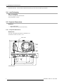

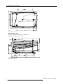
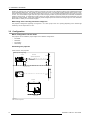
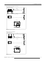

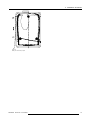
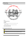
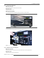
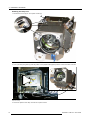
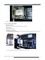
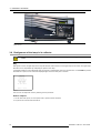

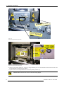
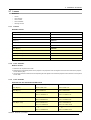
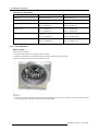
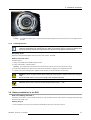
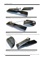
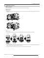
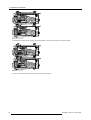
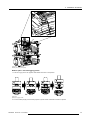
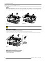
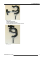


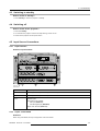

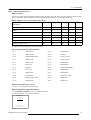
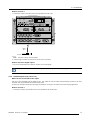
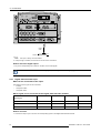
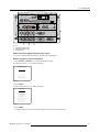
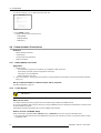
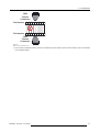
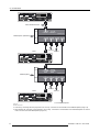
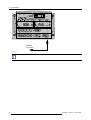
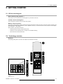
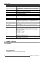
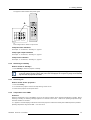
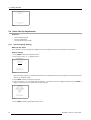
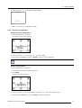
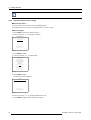
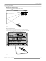
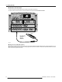
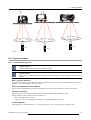


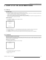
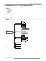
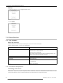
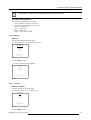


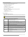
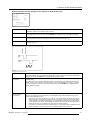
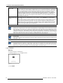
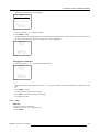


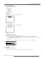


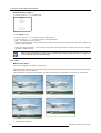


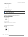
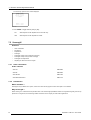
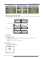

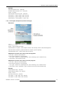


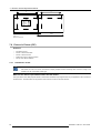
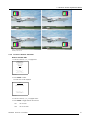


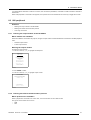
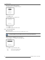
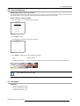
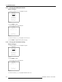
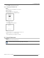
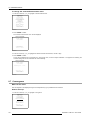


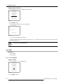
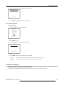
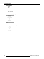
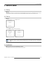
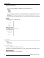
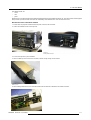
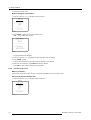

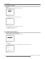
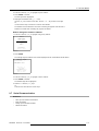
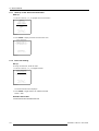
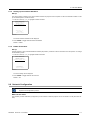
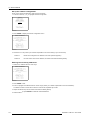
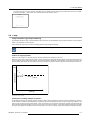

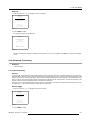
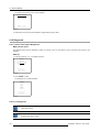
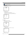
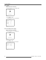
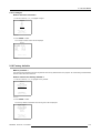
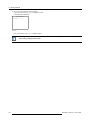
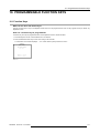

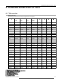
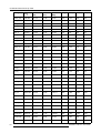
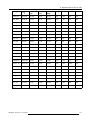


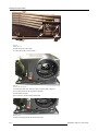
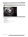
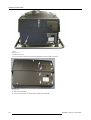
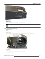


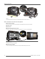
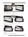
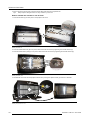


![SLM R12+ Performer [v05]](http://vs1.manualzilla.com/store/data/006296879_1-50504fc86d9979ae79ec928acfe3e08c-150x150.png)
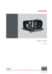
![SLM R12+ Performer [v05]](http://vs1.manualzilla.com/store/data/006791929_1-ebbedd3225f10ee802ba80a2e30391d2-150x150.png)
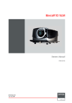
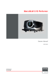


![FLM HD18 [v08]](http://vs1.manualzilla.com/store/data/005664321_1-9e0d84f2b9cac33a4ebfb5904f0dafa1-150x150.png)