1
Simply Engineered Better
Technical Manual
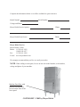
Hood Type
Dishwasher
Model:
M-DH
High Temperature with Built-in Booster
Machine Serial No.
April, 2003
Manual P/N
P.O. Box 4183
Winston-Salem, North Carolina 27115-4183
336/661-1992
Fax: 336/661-1660
113512 Rev A
2674 N. Service Road
Jordan Station, Ontario, Canada L0R 1S0
905/562-4195
Fax: 905/562-4618
www.championindustries.com
Complete the information below so it will be available for quick reference.
Model Number
Serial Number
Voltage and Phase
Moyer Diebel Service Agency
Phone
Moyer Diebel Parts Source
Phone
Moyer Diebel Service
Moyer Diebel (USA)
Phone: 1 (336) 661-1992
1 (800) 858-4477
Fax:
1 (336) 661-1660
E-mail www.moyerdiebel.com
We strongly recommend that you Fax or e-mail your orders.
NOTE: When calling to order parts, be sure to have the model number, serial number,
voltage and phase of your machine.
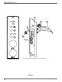
Machine Data Plate with
model & serial number
located on the front of the
lower panel.
COPYRIGHT © 2002 by Moyer Diebel
REVISION RECORD
Revision History
Revision
Date
Revised
Pages
Serial Number
Effectivity
Comments
09/01/01
—
First issue of manual and replacement parts
06/10/02
3
Inserted electrical wiring diagrams.
3/28/03
16, 17
Inserted revised drawing and parts list.
i
REVISION RECORD
ii
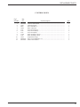
TABLE OF CONTENTS
CONTENTS
Page
REVISION HISTORY ....................................................................................................................
i
GENERAL....................................................................................................................................... 1
INSTALLATION ............................................................................................................................ 2
Unpacking ........................................................................................................................... 2
Electrical Connections ........................................................................................................ 2
Plumbing Connections ........................................................................................................ 4
Ventilation Connections ..................................................................................................... 4
Chemical Connections ........................................................................................................ 5
Completing Installation ...................................................................................................... 5
OPERATION ................................................................................................................................... 6
MAINTENANCE ............................................................................................................................ 7
Daily Cleaning .................................................................................................................... 7
Maintenance ........................................................................................................................ 7
TROUBLESHOOTING .................................................................................................................. 9
REPLACEMENT PARTS ............................................................................................................... 11
ELECTRICAL SCHEMATICS ....................................................................................................... 23
LIST OF FIGURES
Figure 1— Front Panel.....................................................................................................................
Figure 2— Wiring Connection ........................................................................................................
Figure 2— Wash Tank Assembly ....................................................................................................
Figure 3— Wash and Rinse Assemblies ..........................................................................................
Figure 4— Rinse Booster Assembly and Rinse System ..................................................................
Figure 5— Control Cabinet .............................................................................................................
Figure 6— Control Panel .................................................................................................................
2
3
12
14
16
18
20
iii
THIS PAGE
INTENTIONALLY
LEFT BLANK
iv
GENERAL SPECIFICATION
GENERAL SPECIFICATIONS
About this manual
All information, illustrations and specifications contained in this manual are based upon the
latest product information available at the time of publication. Champion constantly improves
its products and reserves the right to make changes at any time or to change specifications or
design without notice and without incurring any obligation.
Organization of Manual
This manual is divided into seven parts:
• General Specifications
• Installation
• Daily Operation
• Cleaning and Maintenance
• Troubleshooting
• Replacement Parts, contains parts diagrams and parts list.
• Electrical Schematics
NOTE:
Unless noted otherwise, dimensions, capacities, temperatures, etc., given in this manual
are U.S. Customary Measures and the Metric Equivalent of the U.S. Customary measures.
Model
The M-DH model is a high temperature (180F/82°C rinse) sanitizing model with booster.
Standard Equipment
•
Automatic operation
•
Door safety switch
•
Built-in electric booster heater
•
Common utility connections
•
Field convertible to corner model
•
•
Electric tank heat
Detergent/chemical connection
provisions
•
Extended wash/de-lime switch
•
Balanced door lift system
•
Low-water tank heat protection
•
Stainless steel front and side panels
•
1-hp drip-proof pump motor
•
Interchangeable upper and lower
spray arms
•
Splash-proof control console
•
International symbols on controls
1
INSTALLATION
INSTALLATION
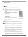
Unpack the dishwasher
!
CAUTION:
Care should be taken when lifting the machine to prevent damage.
NOTE:
The installation of your machine must meet all applicable health and safety codes.
1. Immediately after unpacking the machine, inspect for any shipping damage.
If damage is found, save the packing material and contact the carrier
immediately.
2. Remove the dishwasher from the skid. Move the machine to its
permanent location.
3. Machine must be placed on a sound self-draining floor.
4. Level the machine (if required) by placing a level on the top of the
machine and adjusting the feet. Level the machine from
front-back and side to side.
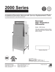
5. Refer to Fig 1. Remove (2) screws that hold the front panel.
Remove the front panel in preparation for service connections.
Figure 1
Remove Front Panel
Electrical Connections
!
WARNING:
Electrical grounding connections must comply with all applicable Electrical Codes.
WARNING:
When working on the dishwasher, disconnect the electric service and place a tag at the
disconnect switch to indicate work is being done on that circuit.
1. A qualified electrician must compare the electrical power supply with the machine electrical specifications before connecting to the incoming service through a fused disconnect
switch.
2. Recommended electrical supply is three phase, permanently wired via wall switch
mounted adjacent to machine. Machine may also be installed on 25A single phase (15A
single phase with reduced rinse heating). Easy on site conversion of standard machine for
any of these requirements.
3. A knock out is provided at the lower right rear corner (as viewed from the front) for
electrical service connection. A fused disconnect switch or circuit breaker (supplied by
others) is required to protect the power supply circuit.
4. Remove (2) lower screws from the front panel of the machine to expose the electrical
controls.
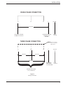
5. Three phase or single phase incoming wire connections are made at the bottom of the
machine’s main terminal block. The main terminal block is located on the side of the front
right post of the dishwasher.
2
INSTALLATION
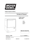
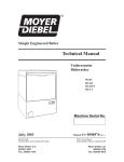
SINGLE PHASE CONNECTION
L2
L1
L3
N
Ground
208/240V
Connect the second
Hot wire to "N"
terminal
Connect (1) Hot wire
to either L1, L2 or L3
THREE PHASE CONNECTION
L2
L1
Earth
Ground
NOTE: Remove Jumper
wires for 3 phase
applications.
L3
N
Ground
208/240V
{
208/240V
208/240V
Connect the
Neutral wire
to "N" terminal
Earth
Ground
Connect (3) Hot wires
to L1, L2 and L3
Figure 2
Wiring Connections
3
INSTALLATION
INSTALLATION (CONT.)
Plumbing Connections
NOTE:
Plumbing connections must comply with all applicable sanitary and plumbing codes.
Water Connections
1. All M-DH dishwashers require a single, hot water supply.
2. The hot water connection to the dishwasher is 1/2” BSP male.
3. The connection is made from underneath the dishwasher.
4. The recommended minimum water temperature is 140F/60°C.
5. A manual shut-off valve for water (supplied by others) should be installed in the supply
line to allow for servicing of the machine. The shut-off valve should be the same size or
larger than the supply line.
6. Install a pressure reducing valve (PRV) in the water supply line if flow pressure exceeds
20-22 PSI/138-151.8kPa.
Drain Connections
1. The dishwasher is a gravity drain machine equipped with 1-1/2” O.D. hose connection
point.
2. The maximum drain flow rate is 15 gallons/min-56.8 liters/min.
3. Drain height for the dishwasher must not exceed 11” (280mm) above the floor level.
4. The drain connection is made to the dishwasher from behind the machine or through an
access hole in the base of the machine.
Ventilation
NOTE:
Ventilation must comply with local sanitary and plumbing codes.
!
4
CAUTION:
Exhaust air should not be vented into a wall, ceiling, or concealed space of a building.
Condensation can cause damage.
INSTALLATION
INSTALLATION (CONT.)
Chemical Connections
NOTE:
Consult a qualified chemical supplier for your chemical needs.
1. A chemical signal terminal block is supplied for chemical dispensing equipment.
2. The terminal block is located below the control panel fuse block.
3. The detergent signal is limited to a maximum load of 1 Amp. Signal voltage is 115VAC.
4. The Rinse aid signal is limited to a maximum load of 1 Amp. Signal voltage is 115VAC.
5. The feeder units must have separate neutrals for detergent and rinse aid connections.
6. A 1/2” detergent injection point is provided at the rear and left side of the dishwasher.
7. Detergent may be added manually, put in three tablespoons of powdered domestic detergent into the wash tank after the machine has been filled, then add another tablespoon full
after every fourth or fifth cycle. This is not recommended except in a temporary situation,
ex: dispensing equipment is down, out of chemical and awaiting supplier, etc.
8. Rinse aid injectors can be purchased separately. There is a 1/4” NPT rinse aid injection
point provided in the final rinse manifold. Use a liquid rinse aid. Contact your local
chemical supplier about product type for factors such as water hardness etc.
Peristaltic Detergent Pump
To prime the peristaltic pump:
1. Insert pump inlet hose into the detergent container.
2. Close machine door and switch machine on.
3. Allow wash tank to fill up then press detergent pump prime switch to prime inlet and
outlet hose.
4. Stop priming when detergent reaches machine.
Machine will not fill unless READY light is on and door is shut. Turn power off before
opening door as machine will cycle again when door is closed. Pump operates during the wash
cycle and is set to run for approximately 10 seconds. Use yellow adjusting tool, supplied with
the instructions, to adjust cam 6 to vary this time. Increase cam gap (away from 0 mark) to
increase pumping time.
5
OPERATION
INITIAL START-UP
Complete the installation
After the plumbing and electrical connections are made, follow the steps below to complete
the installation of your dishwasher.
1. Remove the protective covering from the exterior of the machine.
2. Remove any foreign material from the inside of the machine.
3. Make sure dishwasher power is off.
4. Turn the main water supply on.
5. Turn main power on at the main power service disconnect switch.
6. Install the scrap screens.
7. Make sure that the overflow seats securely in the tank bottom.
8. Make sure doors are fully closed.
9. The control panel is located on the lower right side of machine. Select any cycle (1, 2, 3
minutes).
10. The ON light will glow red and the machine will fill automatically.
11. When machine is full the tank heater and booster heater will begin to heat the water in the
dishwasher. Wait approximately 10 minutes for the wash tank to reach operating temperature. The temperature should be a minimum of 140F/60°C. The machine is ready for use
when the READY light (tick symbol) glows amber.
OPERATION
Operation and Use
1. Before washing make sure that:
• wall mounted on/off switch is switched on;
• water supply is open and water pressure is present;
• pump suction filters are installed in proper location;
• overflow tube is inserted in drain;
• rotating spray arms move freely;
• rinse and detergent containers are full;
2. Select required cycle. Try cycle 3 initially and switch to faster cycles only if necessary.
3. Scrap and preflush all items to be washed. Load items into the rack. Do not overload the
rack. Wash only one layer of silverware in a rack.
4. Open the door and insert the rack into machine. Close door.
5. Machine starts automatically. CYCLE light glows green.
6. Remove rack when the CYCLE light goes out.
NOTE:
Machine will not operate unless the READY light is on. Wash temperature light (thermometer symbol) glows amber when wash temperature has been reached. After removing
racks from machine, DO NOT shut door as machine will start up again.
6
MAINTENANCE
DAILY CLEANING
1. Turn dishwasher and wall switch OFF.
2. Remove the overflow to drain wash tank.
3. Remove scrap screens and wash pump inlet screen. Rinse thoroughly to make sure that
they are clean. Do not bang or beat them on the side of sink or other hard objects as this
will eventually cause them to break or bend thus causing them to fit or work properly.
4. Reinstall the overflow, pump screen, and the scrap screens.
Frequently check and clean the nozzles. Blocked nozzles will prevent the machine from
cleaning properly. To clean the wash/rinse arms:
1. Undo the thumbscrew that holds the arms in place. Do not remove the retaining plate.
2. Twist and remove the end nozzle then withdraw the end cap.
3. Flush arms with water, use a toothpick or paperclip (if necessary) to clear the nozzles.
4. Do not beat the arms on anything to clean nozzles.
5. Replace end cap and end nozzle.
6. Replace arms back into position in machine.
To flush out dishwasher if needed:
1. Leave the overflow out of machine.
2. Close the door.
3. Turn power ON at the dishwasher.
4. Leave on machine on for about 20 seconds. DO NOT leave machine unattended during
this process.
5. Shut power OFF to dishwasher.
7
MAINTENANCE
MAINTENANCE
Before carrying out the cleaning and the maintenance operations, turn off the main disconnect
switch for the equipment.
Do not use corrosive products such as sodium hypochlorite (bleach), acids, steel wool or steel
brushes to clean the inside and the outside of machine.
The presence of calcium and magnesium salt in water can compromise machine performance.
Asked a qualified chemical person to remove the deposits periodically.
Stainless steel surfaces should be cleaned well in order to avoid some oxidation risks, or
chemical reactions.
Optimal Results:
Poor wash results can be noted when residue remains on the dishware. To guard against poor results,
make sure of the following:
• Wash nozzles are clean.
• Rinse nozzles are clean and there is sufficient water supply pressure
20-22 PSI/138-151.8kPa.
• Water temperature is a minimum of 140F/60°C.
• Detergent is in the chemical container
• Pump suction filters are clean.
• Racks are suitable for the dishes and cutlery that are to be washed.
8
TROUBLESHOOTING
TROUBLESHOOTING
In order to find the cause of a breakdown or abnormal operating condition in your dishwasher
please ensure that:
1. All switches are ON
2. Drain and overflow tube are in place and seated
3. Wash pipe and rinse nozzles are clean
4. Scrap screens and pump inlet screen are properly positioned
5. Spray arms are in their proper positions
6. Thermostat(s) are at their correct setting
7. Detergent, and rinse additive dispensers are adequately filled
8. Doors are fully closed.
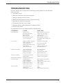
If a problem still exists, use the following table for troubleshooting
CONDITION
CAUSE
SOLUTION
Cycle will not start
Door not closed ................................
Door safety switch faulty .................
Start switch faulty ............................
Main switch off ................................
Overload protector tripped ...............
Not up to temperature ......................
...................................................... —
Make sure doors are fully closed
Contact your service agency
Contact your service agency
Check disconnect
Reset overload in control box
Give machine time to initially reach
temperature
Low or no water
Main water supply is turned off .......
Drain/overflow tube is not
in place and seated ...........................
Machine doors not fully closed ........
Faulty fill valve ................................
Stuck or defective float ....................
Turn on house water supply
Place and seat drain tube
Close doors securely
Contact your service agency
Check floats and clean
Continuous water filling
Stuck or defective float ....................
Fill valve will not close ....................
Drain tube not in place .....................
Pressure switch faulty ......................
Check floats and clean
Clean or replace
Look for drain tube in tank
Replace pressure switch
Any motor not running
Overload protector tripped ............... Reset overload in control box
Defective motor ................................ Contact your service agency
Wash tank water temperature
is low when in use
Incoming water temperature
at machine too low ...........................
Defective thermometer .....................
Defective thermostat ........................
Defective heater element ..................
Defective solenoid valve ..................
Arms not rotating
Rinse nozzles not clean .................... Clean
Bearings worn .................................. Replace
Water supply pressure low ............... Check incoming water pressure
Raise temperature to 140°F/60°C
Check or replace
Check for proper setting or replace
Check or replace
Check or replace
9
TROUBLESHOOTING
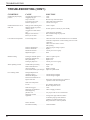
TROUBLESHOOTING (CONT.)
10
CONDITION
CAUSE
SOLUTION
Insufficient pumped spray
pressure
Clogged pump intake screen ............
Clogged spray pipe ..........................
Scrap screen full ...............................
Low water level in tank ....................
Defective pump seal .........................
Clean
Clean
Must be kept clean and in place
Check drain and overflow tube
Contact service agent
Insufficient final rinse or no
final rinse
Faulty pressure reducing valve ........
Improper setting on pressure
reducing valve ..................................
Clogged rinse nozzle and/or
pipe ...................................................
Improper water line size ...................
Rinse cycle too short ........................
Clean or replace
Set flow pressure to 20-22 psi [138-151kPa]
Clean with paper clip/delime
Have installer change to proper size
Check timer
Low final rinse temperature
Low incoming water ........................ Check the booster be sure the thermostat is set to maintain
180°F/82°C temperature. Check incoming water is set min.
140°F/60°C.
Check valve to be sure it is clean
and operating.
Defective thermometer ..................... Check for proper setting or replace
Defective thermostat ........................ Replace
Bad booster element ......................... Contact your service agency
High limit tripped ............................. Reset
Machine leaking
Leaking at chemical injector ............
Leaking at chemical hose .................
Pump seal leaking ............................
Leaking at pump hose ......................
Check or replace injector
Replace hoses
Replace seal
Contact your service agency
Water splashing out door
Nozzles/End caps missing ................
Wash nozzles blocked ......................
Arms not rotating .............................
Door handle twisted (pass through) .
Replace caps
Clean
Replace bearings
Adjust or replace handle
Poor washing results
Detergent dispenser not
operating properly ............................ Contact detergent supplier
Insufficient detergents ...................... Contact detergent supplier
Food Soil concentration too
high in wash tank ............................. Drain tank, clean and refill every 2 hours of
operation or after each meal period.
Wash water temperature
too low .............................................. See condition “Wash Tank
Water Temperature” above
Wash arm clogged ............................ Clean
Improperly scraped dishes ............... Check scraping procedures
Ware improperly
placed in rack ................................... Use proper racks. Do not overload racks
Improperly cleaned
equipment ......................................... Unclog wash sprays and rinse nozzles
to maintain proper pressure and flow
conditions. Overflows must be open.
Keep wash water as clean as possible.
Electric elements
has soil/lime buildup ........................ Clean and delime
REPLACEMENT PARTS
REPLACEMENT
PARTS
11
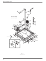
REPLACEMENT PARTS
26
3
25
34
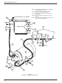
Note #3
Note #1: Use Loctite 290
Note #2: Use thread tape
Note #3: Use Loctite 243
10
11
9
Note #3
3
Note #1
15
16
2
1
14
5
30
4
7
13
2
31
12
17
18
6
33
33
31
32
32
29
8
18
31
31
27
16
32
(DEMA HOLE PLUG)
15
28
24
Note #2
14
23
31
36
35
37
38
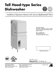
Tank Bottom
Figure 3
Wash Tank Assy
12
ELEMENT
LOCKNUTS
20
19
THERMOSTAT
PROBE
22
32
39
ELEMENT
GASKETS
21
REPLACEMENT PARTS
WASH TANK ASSEMBLY
Fig.3
Item No.
Part
No.
1
2
3
4
5
6
7
8
9
10
11
12
13
14
15
16
17
18
19
20
21
22
23
24
25
26
27
28
29
30
31
32
33
34
35
36
37
38
39
32590001
ASS24
40030000
6037
1896
3904
C160603
24.38210
C16301
C180704
1238
ARP229
ARP241
8835
8568
8058
8106
88461
8800
30201
3032
3033
3031
30071
60030092
88021
1557
1560
60080017
60080015
8566
8108
ASS36
32510012
111151
110854
110750
107589
104584
Part Description
Hose Outlet ..............................................................................................
Hose Clamp .............................................................................................
Spindle .....................................................................................................
Backnut 126*40mm ................................................................................
Drain Waste Gasket .................................................................................
Wash Pump Assy ....................................................................................
Pump Inlet Flange ...................................................................................
Hose Inlet ................................................................................................
Drain Outlet .............................................................................................
Overflow Pipe .........................................................................................
Wash Inlet Filter ......................................................................................
Oring ........................................................................................................
Oring ........................................................................................................
Set Screw 5/6” x 1/2” ..............................................................................
Washer Spring 5/16” ...............................................................................
Nut 5/16” .................................................................................................
Nut Hex M6 .............................................................................................
Bolt Hex Head M6 x 12 ..........................................................................
Screw Pan Head M4 x 6 ..........................................................................
Thermostat ...............................................................................................
Gland Nut ................................................................................................
Gasket Gland ...........................................................................................
Gland Bulkhead .......................................................................................
Element Wash 1.8KW .............................................................................
Door Switch Assy ....................................................................................
Screw Pan Head M4 x 30 ........................................................................
Rack Guide ..............................................................................................
Rack Guide Bracket ................................................................................
Bolt Truss Head M5 x 12 ........................................................................
Bolt Hex M6 x 16 ....................................................................................
Washer Spring 1/4” .................................................................................
Nut Dome M6 ..........................................................................................
Hose Clamp .............................................................................................
Wash Manifold ........................................................................................
C-Clip Float Switch (per float ball) .........................................................
Dual Float Switch ....................................................................................
Gasket float switch ..................................................................................
Washer, lock 1/2” ....................................................................................
Nut, Plain (1-2-13) ..................................................................................
Qty.
1
2
2
1
1
1
1
1
1
1
1
1
1
2
2
2
4
2
2
1
1
1
1
1
1
2
1
1
2
4
8
4
2
1
2
1
1
1
1
13
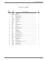
REPLACEMENT PARTS
13
9
10
9
12
8
5
11
8
7
7
2
1
5
14
3
4
5
15
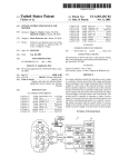
Figure 4
Wash and Rinse Arm Assemblies
14
6
2
1
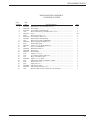
REPLACEMENT PARTS
WASH AND RINSE ARM ASSEMBLIES
Fig.4
Item No.
Part
No.
1
2
3
4
5
6
7
8
9
10
11
12
13
14
15
16
17
40030037
ARP018
32530020
32590023
C190624
40030021
60080017
40030010
60020001
81530002
81530001
40030002
40030073
40030074
40030072
32510014
81510013
Part Description
Plug, Wash End .......................................................................................
O-ring, Wash Plug ...................................................................................
Wash Arm ...............................................................................................
Wash Hub ................................................................................................
Plastic Bushing ........................................................................................
Wash Arm ...............................................................................................
Screw M5 x 12 Truss Head .....................................................................
Plug, Rinse Arm ......................................................................................
Nozzle, Rinse ..........................................................................................
Rinse Arm ...............................................................................................
Rinse Arm ...............................................................................................
Rinse Arm Hub ........................................................................................
Rinse Arm Spindle ..................................................................................
Wash Spindle Nut ....................................................................................
Wash Arm Spindle ..................................................................................
Wash Arm Assembly (includes items 1-6) .............................................
Rinse Arm Assembly (include items 5, 7-12) .........................................
Qty.
2
2
1
1
4
1
2
2
6
1
1
1
1
1
1
A/R
A/R
15
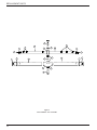
REPLACEMENT PARTS
BULKHEAD NUT & GASKET
9
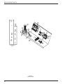
NOTE #1. USE THREAD TAPE ON CROX AND THREADED
FITTINGS TO SEAL JOINTS.
NOTE #2. USE 243 LOCTITE ON SPINDLE THREAD
BEFORE FITTING INTO WASH HUB.
NOTE #3. USE 243 OR 290 LOCTITE TO LOCK BOLT TO
BASE PLATE.
NOTE #4. USE 10-12 TURNS OF THREAD TAPE ON ALL
JOINTS.
NOTE #5. ENSURE LINE STRAINER AND SOLENOID FLOW
DIRECTIONS ARE AS SHOWN.
NOTE #1
16
7
NOTE #2
WASH HUBS
13
4
16
2
18
NOTE #5
20
NOTE #4
17
21
NOTE #4
22
NOTE #4
5
FLOW DIRECTION
2
19
24
5
25
2
1
15
14
5
26
3
8
2
10
6
11
12
5
Figure 5
Rinse Booster Assmbly and Rinse System
16
23
NOTE #3
REPLACEMENT PARTS
RINSE BOOSTER ASSEMBLY
AND RINSE SYSTEM
Fig.5
Item No.
Part
No.
1
2
3
4
5
6
7
8
9
10
11
12
13
14
15
16
17
18
19
20
21
22
23
24
25
26
40010061
60090028
60060066
1672
60060073
88461
40030048
40020061
6083
60090060
8566
60060067
6001
60080052
60030088
40030072
6153
3324
3321
60060003
6075
6950
6047
60080009
60080024
3005
Part Description
Rinse Booster Assy (Includes Item 26) ...................................................
Hose Clamp .............................................................................................
Tee 12MM x 3/8 BSP Branch .................................................................
Rinse Solenoid Assy (Includes Items 17-25) ..........................................
Hose .........................................................................................................
Bolt Hex SST M6 x 12 ...........................................................................
Crox Tailpiece MCO 1/2". ......................................................................
Bracket Rinse tank Mounting ..................................................................
Elbow Crox-Female 15MM Brass ..........................................................
Ball Polypropylene PB030 7/16" ............................................................
Washer Spring M6 ..................................................................................
Socket 3/8 x 1/8 Nylon Reducing ...........................................................
Nut Crox 15MM Brass ............................................................................
Bolt Pan Slot M3 x 6 ...............................................................................
Thermostat ...............................................................................................
Wash Spindle ...........................................................................................
Tailpiece 1/2 x 1/2 ...................................................................................
Coil, Solenoid 240V 10W LED ..............................................................
Body, Solenoid EVSI10 ..........................................................................
Nipple 1/2" x 2" Brass .............................................................................
Musen Ring Saddle Clamp Brass 20MM ................................................
Strainer Line 1/2" ....................................................................................
Nipple Hex 1/2" .......................................................................................
Nut SST Hex M10 ...................................................................................
MS Hex SST 304 M10 x 60 ....................................................................
Element 5KW 208-240V (Includes Cap & Gasket) ................................
Qty.
1
6
1
1
15ft
1
1
1
1
1
1
1
1
1
1
2
1
1
1
1
1
1
1
2
1
1
17
REPLACEMENT PARTS
11
17
18
3
12
17
15
16
17
10
13
20
8
6
7
5
17
16
1
19
2
9
14
4
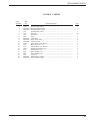
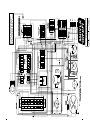
Screw assignment
diagram
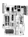
Figure6
Control Cabinet
18
REPLACEMENT PARTS
CONTROL CABINET
Fig.6
Item No.
Part
No.
1
2
3
4
5
6
7
8
9
10
11
12
13
14
15
16
17
18
19
20
32275
60030089
60030090
3227
3231
3020
3028
60030081
60030080
60030083
32823
8816
8151
16611
8565
8802
8801
3894
60030097
60030082
Part Description
Terminal Strip 6 Way ..............................................................................
Bushing Snap-In 25mm ...........................................................................
Bushing Snap-In 30mm ...........................................................................
Terminal Strip 3 Way ..............................................................................
Din Rail ...................................................................................................
Thermostat ...............................................................................................
Screw. ......................................................................................................
2 Pole Base ..............................................................................................
Relay 2 Pole 240V ...................................................................................
Contactor 240V .......................................................................................
Timer Triple Cycle 180sec ......................................................................
Brass Stud 3/16 x 3/4 ..............................................................................
Nut Hex Brass 3/16 Pressed ....................................................................
Wiring Tray Bracket Assy .......................................................................
Washer Brass 3/16 ...................................................................................
Screw Pan M4 x 25 .................................................................................
Screw Pan M4 x 12 .................................................................................
Capacitor .................................................................................................
On/Off Power Switch ..............................................................................
Wire Clip Relay Base ..............................................................................
Qty.
1
1
1
1
12”
1
2
2
2
1
1
1
1
1
1
4
6
1
1
2
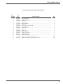
19
REPLACEMENT PARTS
1
2
8
12
12
3
5
9
6
7
4
10
11
NOTE: 1 SECURE GAUGES USING U CLAMP AND LOCKNUT SUPPLIED
Figure 7
Control Panel
20
REPLACEMENT PARTS
CONTROL PANEL
Fig.7
Item No.
Part
No.
1
2
3
4
5
6
7
8
9
10
11
12
40020060
30411
8800
30415
3135
3134
3133
31385
3138
35021
60080017
40070006
Part Description
Control Cabinet Panel .............................................................................
4 Position Switch .....................................................................................
Screw, Pan M4 x 6 ..................................................................................
Knob, 4 Position ......................................................................................
Lens, Neon (Green) .................................................................................
Lens, Neon (Amber) ................................................................................
Lens, Neon (Red) ....................................................................................
Neon Assembly (Green) ..........................................................................
Neon Assembly (Clear) ...........................................................................
Temperature Gauge .................................................................................
Screw, Truss Head M5 x 12 ....................................................................
Label Contol Cabinet ..............................................................................
Qty.
1
1
2
1
1
2
1
1
3
2
2
1
21
REPLACEMENT PARTS
THIS PAGE
INTENTIONALLY
LEFT BLANK
22
ELECTRICAL SCHEMATICS
ELECTRICAL
SCHEMATICS
23
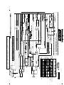
080221
REV
C
7/29/02
DATE
M-DH ELECTRIC
For a more detailed explaination of
wiring connections, see page 3
Fig. 2 of Installation section in manual
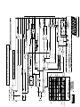
080223
REV
C
7/29/02
DATE
M-DH ELECTRIC
For a more detailed explaination of
wiring connections, see page 3
Fig. 2 of Installation section in manual
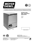
080133
REV
D
7/29/02
DATE
M-DH ELECTRIC
For a more detailed explaination of wiring connections
see page 3 Fig. 2 of Installation section of manual.
For a more detailed explaination of wiring connections
see page 3 Fig. 2 of Installation section of manual.
080134
E
7/29/02
DATE
M-DH ELECTRIC
REV