1
NOTICE
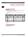
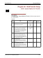
Note that when converting this document from its original format to a .pdf file,
some minor font and format changes may occur causing slight variations. When
viewing and printing this document, we cannot guarantee that your specific PC or
printer will support all of the fonts or graphics. Therefore, when you view the
document fonts may be substituted and your individual printer may not have the
capability to print the document correctly.
PROGRAMMING MANUAL
INT-1073 (IPK II)
D
OCUMENT REVISION 1
ELEASE 1000)
(R
NEC Unified Solutions, Inc. reserves the right to change the specifications, functions, or features at
any time without notice.
NEC Unified Solutions, Inc. has prepared this document for use by its employees and customers. The
information contained herein is the property of NEC Unified Solutions, Inc. and shall not be reproduced
without prior written approval of NEC Unified Solutions, Inc.
Dterm is a registered trademark of NEC Corporation and Electra Elite is a registered trademark of NEC
America, Inc. Windows is a registered trademark of Microsoft Corporation. AT&T is a registered
trademark of American Telephone and Telegraph Company. Lucent Technologies is a trademark or
service mark of Lucent Technologies Inc. Nortel Networks and the Nortel Networks logo are
trademarks of Nortel Networks.
Copyright 2006
NEC Infrontia, Inc.
6535 N. State Highway 161
Irving, TX 75039-2402
Technology Development
Preface
THIS MANUAL
The Programming Manual provides the technician with all of the necessary information for
programming the Electra Elite IPK II system.
Programming can be accomplished using a PC or a Multiline Terminal.
SUPPORTING DOCUMENTS
Electra Elite IPK II General Description Manual
This Manual provides general information about the system, its features, system configuration and
standards. This manual provides an overview of the Electra Elite IPK II system and can be used to
present information to potential customers.
Electra Elite IPK II System Hardware Manual
The System Hardware Manual is provided for the system installer. This manual has detailed
instructions for installing the Electra Elite IPK II KSU, ETUs, Multiline Terminals, and optional
equipment.
Electra Elite IPK II Features and Specifications Manual
This manual provides detailed information for each of the system features. If you are not familiar with
the features, the Table of Contents lists each of the features and where to find the feature within the
manual.
Electra Elite IPK II Key-Common Channel Interoffice Signaling (K-CCIS) Manual
This manual provides information installing and programming the Key-Common Channel Interoffice
Signaling (K-CCIS) System.
TABLE OF CONTENTS
___________________________________________________________________________________
Chapter 1
Introduction
Section 1
Before You Start Programming ......................................................... 1-1
Section 2
How to Use Manual ............................................................................. 1-1
Section 3
How to Enter Programming Mode ..................................................... 1-2
Section 4
How to Exit Programming Mode ....................................................... 1-3
Section 5
Using Keys to Move Around in the Programs ................................. 1-4
Section 6
Programming Names and Text Messages ....................................... 1-5
Section 7
Using Softkeys For Programming .................................................... 1-6
Section 8
What the Softkey Display Prompts Mean ......................................... 1-7
Section 9
System Number Plan/Capacities ....................................................... 1-8
Chapter 2
Section 1
Programming the Electra Elite IPK II
Programming Your System ............................................................... 2-1
Program 10 : System Configuration Setup
10-01 : Time and Date ........................................................................... 2-3
10-02 : Location Setup ........................................................................... 2-4
10-03 : ETU Setup ................................................................................. 2-5
10-04 : Music On Hold Setup .............................................................. 2-13
10-05 : General Purpose Relay Setup ................................................. 2-14
10-06 : ISDN BRI Setup ....................................................................... 2-15
10-08 : Ringing Setup .......................................................................... 2-16
10-09 : DTMF and Dial Tone Circuit Setup ..........................................2-17
10-12 : CPUII Network Setup .............................................................. 2-18
10-13 : In-DHCP Server Setup ............................................................ 2-20
___________________________________________________________________________________
Programming
i
Document
Revision 1
Electra Elite IPK II
___________________________________________________________________________________
10-14 : Managed Network Setup ......................................................... 2-21
10-15 : Client Information Setup .......................................................... 2-22
10-16 : Option Information Setup ........................................................ 2-23
10-20 : LAN Setup for External Equipment ......................................... 2-25
10-21 : CPUII Hardware Setup ............................................................ 2-26
10-24 : Daylight Savings Setup ........................................................... 2-27
10-38 : BGM Resource Setup ............................................................. 2-29
Program 11 : System Numbering
11-01 : System Numbering .................................................................. 2-31
11-02 : Extension Numbering .............................................................. 2-40
11-04 : Virtual Extension Numbering ................................................... 2-42
11-06 : ACI Extension Numbering ....................................................... 2-44
11-07 : Department Group Pilot Numbers ........................................... 2-45
11-08 : ACI Group Pilot Number .......................................................... 2-46
11-09 : Trunk Access Code ................................................................. 2-47
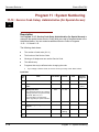
11-10 : Service Code Setup (for System Administrator) ...................... 2-49
11-11 : Service Code Setup (for Setup/Entry Operation) .................... 2-52
11-12 : Service Code Setup (for Service Access) ............................... 2-56
11-13 : Service Code Setup (for ACD) ................................................ 2-60
11-14 : Service Code Setup (for Hotel) ............................................... 2-62
11-15 : Service Code Setup, Administrative (for Special Access) ....... 2-64
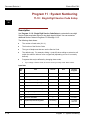
11-16 : Single Digit Service Code Setup ............................................. 2-66
11-17 : ACD Group Pilot Number ........................................................ 2-68
Program 12 : Night Mode Setup
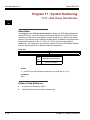
12-01 : Night Mode Function Setup ..................................................... 2-69
12-02 : Automatic Night Service .......................................................... 2-70
12-03 : Weekly Night Service Switching .............................................. 2-72
12-04 : Holiday Night Service Switching .............................................. 2-74
12-05 : Night Mode Group Assignment for Extensions ....................... 2-75
12-06 : Night Mode Group Assignment for Trunks .............................. 2-76
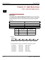
12-07 : Text Data for Night Mode ........................................................ 2-77
___________________________________________________________________________________
ii
Table of Contents
Electra
Elite IPK II
Document Revision 1
___________________________________________________________________________________
12-08 : Night Mode Service Range ...................................................... 2-78
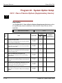
Program 13 : Speed Dialing
13-01 : Speed Dialing Option Setup .................................................... 2-79
13-02 : Group Speed Dialing Bins ....................................................... 2-80
13-03 : Speed Dialing Group Assignment for Extensions ....................2-81
13-04 : Speed Dialing Number and Name ........................................... 2-82
13-05 : Speed Dial Trunk Group .......................................................... 2-84
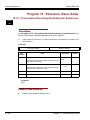
Program 14 : Trunk, Basic Setup
14-01 : Basic Trunk Data Setup ........................................................... 2-85
14-02 : Analog Trunk Data Setup ........................................................ 2-91
14-04 : Behind PBX Setup ................................................................... 2-94
14-05 : Trunk Group ............................................................................ 2-95
14-06 : Trunk Group Routing ............................................................... 2-96
14-07 : Trunk Access Map Setup ........................................................ 2-98
14-08 : Music on Hold Source for Trunks .......................................... 2-100
14-09 : Conversation Recording Destination for Trunks .................... 2-101
14-13 : CCIS System Route ID .......................................................... 2-102
14-14 : CCIS Trunk CIC Assignment ................................................. 2-103
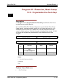
Program 15 : Extension, Basic Setup
15-01 : Basic Extension Data Setup ................................................. 2-105
15-02 : Multiline Telephone Basic Data Setup ................................... 2-107
15-03 : Single Line Telephone Basic Data Setup .............................. 2-113
15-05 : IP Telephone Terminal Basic Data Setup ............................. 2-116
15-06 : Trunk Access Map for Extensions ......................................... 2-117
15-07 : Programmable Function Keys ............................................... 2-118
15-08 : Incoming Virtual Extension Ring Tone Setup ........................ 2-128
15-09 : Virtual Extension Ring Assignment ....................................... 2-130
15-10 : Incoming Virtual Extension Ring Tone Order Setup .............. 2-131
15-11 : Virtual Extension Delayed Ring Assignment ......................... 2-133
15-12 : Conversation Recording Destination for Extensions ............. 2-134
15-14 : Programmable One-Touch Keys ........................................... 2-135
___________________________________________________________________________________
Programming
iii
Document
Revision 1
Electra Elite IPK II
___________________________________________________________________________________
15-15 : Wireless DECT Terminal Basic Data Setup .......................... 2-136
15-17 : CO Message Waiting Indication ............................................ 2-139
15-18 : Virtual Extension Key Enhanced Options .............................. 2-140
15-20 : LCD Line Key Name Assignment .......................................... 2-141
Program 16 : Department Group Setup
16-01 : Department Group Basic Data Setup .................................... 2-143
16-02 : Department Group Assignment for Extensions ..................... 2-146
16-03 : Secondary Department Group .............................................. 2-147
Program 20 : System Option Setup
20-01 : System Options ..................................................................... 2-149
20-02 : System Options for Multiline Telephones .............................. 2-151
20-03 : System Options for Single Line Telephones ......................... 2-154
20-04 : System Options for Virtual Extensions .................................. 2-156
20-06 : Class of Service for Extensions ............................................. 2-157
20-07 : Class of Service Options (Administrator Level) ..................... 2-158
20-08 : Class of Service Options (Outgoing Call Service) ................. 2-161
20-09 : Class of Service Options (Incoming Call Service) ................. 2-164
20-10 : Class of Service Options (Answer Service) ........................... 2-166
20-11 : Class of Service Options (Hold/Transfer Service) ................. 2-168
20-12 : Class of Service Options (Charging Cost Service) ............... 2-171
20-13 : Class of Service Options (Supplementary Service) .............. 2-172
20-14 : Class of Service Options for DISA/E&M ................................ 2-177
20-15 : Ring Cycle Setup ................................................................... 2-179
20-16 : Selectable Display Messages ............................................... 2-181
20-17 : Operator’s Extension ............................................................. 2-184
20-18 : Service Tone Timers ............................................................. 2-185
20-19 : System Options for Caller ID ................................................. 2-187
20-20 : Message Setup for Non-Caller ID Data ................................. 2-188
20-21 : System Options for Long Conversation ................................. 2-189
20-22 : System Options for Wireless DECT Service ........................ 2-190
20-23 : System Options for CTI ......................................................... 2-191
___________________________________________________________________________________
iv
Table of Contents
Electra
Elite IPK II
Document Revision 1
___________________________________________________________________________________
20-25 : ISDN Options ......................................................................... 2-192
20-26 : Multiplier Changing CO ......................................................... 2-194
20-28 : Trunk to Trunk Conversation ................................................. 2-195
20-29 : Timer Class for Extension ..................................................... 2-196
20-30 : Timer Class for Trunks .......................................................... 2-197
20-31 : Timer Class Timer Assignment ............................................. 2-198
Program 21 : Outgoing Call Setup
21-01 : System Options for Outgoing Calls ....................................... 2-201
21-02 : Trunk Group Routing for Extensions ..................................... 2-204
21-03 : Trunk Group Routing for Trunks ............................................ 2-205
21-04 : Toll Restriction Class for Extensions ..................................... 2-206
21-05 : Toll Restriction Class ............................................................. 2-207
21-06 : Toll Restriction Table Data Setup .......................................... 2-210
21-07 : Toll Restriction Override Password Setup ............................. 2-213
21-08 : Repeat Dial Setup ................................................................. 2-214
21-09 : Dial Block Setup .................................................................... 2-215
21-10 : Dial Block Restriction Class Per Extensions ......................... 2-216
21-11 : Extension Ringdown (Hotline) Assignment ........................... 2-217
21-12 : ISDN Calling Party Number Setup for Trunks ....................... 2-218
21-13 : ISDN Calling Party Number Setup for Extensions ................. 2-219
21-14 : Walking Toll Restriction Password Setup .............................. 2-220
21-15 : Individual Trunk Group Routing for Extensions ..................... 2-221
21-21 : Toll Restriction for Trunks (Seized Trunk Basis Setting) ....... 2-222
21-22 : CO Message Waiting Indication - Call Back Settings ............ 2-223
Program 22 : Incoming Call Setup
22-01 : System Options for Incoming Calls ....................................... 2-225
22-02 : Incoming Call Trunk Setup ................................................... 2-227
22-03 : Trunk Ring Tone Range ........................................................ 2-228
22-04 : Incoming Extension Ring Group Assignment ........................ 2-230
22-05 : Incoming Trunk Ring Group Assignment ............................... 2-231
22-06 : Normal Incoming Ring Mode ................................................. 2-232
___________________________________________________________________________________
Programming
v
Document
Revision 1
Electra Elite IPK II
___________________________________________________________________________________
22-07 : DIL Assignment ..................................................................... 2-233
22-08 : DIL/IRG No Answer Destination ............................................ 2-234
22-09 : DID Basic Data Setup ........................................................... 2-235
22-10 : DID Translation Table Setup ................................................. 2-237
22-11 : DID Translation Number Conversion .................................... 2-239
22-12 : DID Intercept Ring Group ...................................................... 2-243
22-13 : DID Trunk Group to Translation Table Assignment .............. 2-245
22-14 : VRS Delayed Message for IRG ............................................. 2-246
22-15 : VRS Waiting Message for Department Group ...................... 2-247
22-16 : Private Call Refuse Target Area Setup ................................. 2-248
22-17 : Dial-In Conversion Table Area Setup for Time Pattern ......... 2-249
22-18 : Private Call Assignment Setup .............................................. 2-250
Program 23 : Answer Features Setup
23-02 : Call Pickup Groups ................................................................ 2-251
23-03 : Universal Answer/Auto Answer ............................................. 2-252
23-04 : Ringing Line Preference for Virtual Extensions ..................... 2-254
Program 24 : Hold/Transfer Setup
24-01 : System Options for Hold ....................................................... 2-255
24-02 : System Options for Transfer ................................................. 2-257
24-03 : Park Group ............................................................................ 2-259
24-04 : Automatic Trunk-to-Trunk Transfer Target Setup ................. 2-260
24-05 : Department Group Transfer Target Setup ............................ 2-261
24-09 : Call Forward Split Settings .................................................... 2-262
Program 25 : DID/DISA Setup
25-01 : VRS/DISA Line Basic Data Setup ......................................... 2-265
25-02 : DID/DISA VRS Message ....................................................... 2-266
25-03 : VRS/DISA Transfer Ring Group With Incorrect Dialing ......... 2-267
25-04 : VRS/DISA Transfer Ring Group With No Answer/Busy ........ 2-268
25-05 : VRS/DISA Error Message Assignment ................................. 2-269
25-06 : VRS/DISA One-Digit Code Attendant Setup ......................... 2-270
25-07 : System Timers for VRS/DISA ............................................... 2-272
___________________________________________________________________________________
vi
Table of Contents
Electra
Elite IPK II
Document Revision 1
___________________________________________________________________________________
25-08 : DISA User ID Setup ............................................................... 2-274
25-09 : Class of Service for DISA Users ............................................ 2-275
25-10 : Trunk Group Routing for DISA .............................................. 2-276
25-11 : DISA Toll Restriction Class ................................................... 2-277
25-12 : Alternate Trunk Group Routing for DISA ............................... 2-278
25-13 : System Option for DISA ........................................................ 2-279
Program 26 : ARS Service
26-01 : Automatic Route Selection Service ....................................... 2-281
26-02 : Dial Analysis Table for ARS/LCR .......................................... 2-283
26-03 : ARS Dial Treatments ............................................................. 2-285
26-04 : ARS Class of Service ............................................................ 2-287
26-05 : LCR Carrier Table ................................................................. 2-288
26-06 : LCR Authorization Table ....................................................... 2-289
26-07 : LCR Cost Center Code Table ................................................ 2-290
26-08 : LCR Manual Override Access Code Table ............................ 2-291
26-09 : LCR Manual Override Exemption Table ................................ 2-292
26-11 : Transit Network ID Table ....................................................... 2-294
Program 30 : DSS/DLS Console Setup
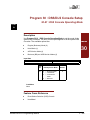
30-01 : DSS Console Operating Mode .............................................. 2-295
30-02 : DSS Console Extension Assignment .................................... 2-296
30-03 : DSS Console Key Assignment .............................................. 2-297
30-05 : DSS Console Lamp Table ..................................................... 2-304
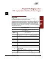
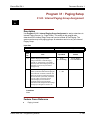
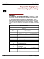
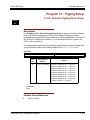
Program 31 : Paging Setup
31-01 : System Options for Internal/External Paging ......................... 2-307
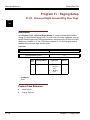
31-02 : Internal Paging Group Assignment ........................................ 2-309
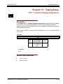
31-03 : Internal Paging Group Settings ............................................. 2-310
31-04 : External Paging Zone Group ................................................. 2-313
31-05 : Universal Night Answer/Ring Over Page ............................... 2-314
31-06 : External Speaker Control ...................................................... 2-315
31-07 : Combined Paging Assignments ............................................ 2-317
31-08 : BGM on External Paging ....................................................... 2-318
___________________________________________________________________________________
Programming
vii
Document
Revision 1
Electra Elite IPK II
___________________________________________________________________________________
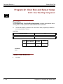
Program 32 : Door Box and Sensor Setup
32-01 : Door Box Timers ................................................................... 2-319
32-02 : Door Box Ring Assignment ................................................... 2-320
32-03 : Door Box Basic Setup ........................................................... 2-321
Program 33 : CTA and ACI Setup
33-01 : ACI Port Type Setup ............................................................. 2-323
33-02 : ACI Department Calling Group .............................................. 2-324
Program 34 : Tie Line Setup
34-01 : E&M Tie Line Basic Setup ..................................................... 2-325
34-02 : E&M Tie Line Class of Service .............................................. 2-327
34-03 : Trunk Group Routing for E&M Tie Lines ............................... 2-328
34-04 : E&M Tie Line Toll Restriction Class ...................................... 2-329
34-05 : Tie Line Outgoing Call Restriction ......................................... 2-330
34-06 : Add / Delete Digit for E&M Tie Line ....................................... 2-331
34-07 : E&M Tie Line Timer ............................................................... 2-332
34-08 : Toll Restriction Data for E&M Tie Lines ................................ 2-333
34-09 : ANI/DNIS Service Options .................................................... 2-334
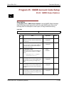
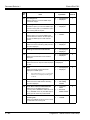
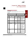
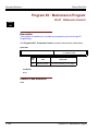
Program 35 : SMDR Account Code Setup
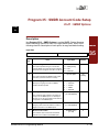
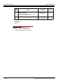
35-01 : SMDR Options ...................................................................... 3-337
35-02 : SMDR Output Options ........................................................... 3-339
35-03 : SMDR Port Assignment for Trunk Group .............................. 3-342
35-04 : SMDR Port Assignment for Department Groups ................... 3-343
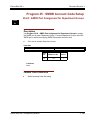
35-05 : Account Code Setup ............................................................. 3-344
35-06 : Verified Account Code Table ................................................. 3-346
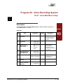
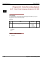
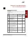
Program 40 : Voice Recording System
40-01 : Voice Mail Basic Setup .......................................................... 2-347
40-02 : Mailbox Setup ........................................................................ 2-349
40-03 : Message Recording Setup .................................................... 2-350
40-04 : Live Recording Setup ............................................................ 2-351
40-05 : Call Information Setup ........................................................... 2-352
40-06 : Voice Mail Automated Attendant Data Setup ........................ 2-353
___________________________________________________________________________________
viii
Table of Contents
Electra
Elite IPK II
Document Revision 1
___________________________________________________________________________________
40-07 : Voice Prompt Language Assignment for VRS ....................... 2-354
40-08 : Voice Prompt Language Assignment for Mailboxes .............. 2-355
40-09 : Voice Mail Multiple Address Group Setup ............................. 2-356
40-10 : Voice Announcement Service Option .................................... 2-357
40-11 : Pre-Amble Message Assignment .......................................... 2-359
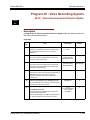
Program 41 : ACD Setup
41-01 : System Options for ACD ....................................................... 2-361
41-02 : ACD Group and Agent Assignments ..................................... 2-362
41-03 : Incoming Ring Group Assignment for ACD Group ................ 2-363
41-04 : ACD Group Supervisor ......................................................... 2-365
41-05 : ACD Agent Work Schedules ................................................. 2-366
41-06 : Trunk Work Schedules .......................................................... 2-367
41-07 : ACD Weekly Schedule Setup ................................................ 2-368
41-08 : ACD Overflow Options .......................................................... 2-369
41-09 : ACD Overflow Table Setting .................................................. 2-371
41-10 : ACI Delay Announcement ..................................................... 2-372
41-11 : VRS Delay Announcement .................................................... 2-373
41-12 : Night Announcement Setup ................................................... 2-375
41-13 : VRS Message Number for Night Announcement .................. 2-376
41-14 : ACD Options .......................................................................... 2-377
41-15 : ACD Queue Alarm Information .............................................. 2-379
41-16 : ACD Threshold Overflow ....................................................... 2-381
41-17 : ACD Login Mode Setup ......................................................... 2-382
41-18 : ACD Agent Identity Code Setup ............................................ 2-383
41-20 : ACD Queue Display Settings ................................................ 2-384
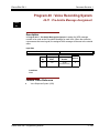
Program 42 : Hotel Setup
42-01 : System Options for Hotel/Motel ............................................. 2-387
42-02 : Hotel/Motel Telephone Setup ................................................ 2-388
42-03 : Class of Service Options (Hotel/Motel) .................................. 2-389
42-04 : Hotel Mode One-Digit Service Codes .................................... 2-391
42-05 : Hotel Room Status Printer ..................................................... 2-392
___________________________________________________________________________________
Programming
ix
Document
Revision 1
Electra Elite IPK II
___________________________________________________________________________________
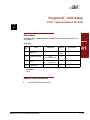
Program 44 : ARS/F-Route Setup
44-01 : System Options for ARS/F-Route ......................................... 2-393
44-02 : Dial Analysis Table for ARS/F-Route Access ........................ 2-394
44-03 : Dial Analysis Extension Table ............................................... 2-396
44-04 : ARS/F-Route Selection for Time Schedule ........................... 2-398
44-05 : ARS/F-Route Table ............................................................... 2-399
44-06 : Additional Dial Table ............................................................. 2-401
44-07 : Gain Table for ARS/F-Route Access .................................... 2-402
44-08 : Time Schedule for ARS/F-Route ........................................... 2-404
44-09 : Weekly Schedule for ARS/F-Route ....................................... 2-406
44-10 : Holiday Schedule for ARS/F-Route ....................................... 2-407
Program 45 : Voice Mail Integration
45-01 : Voice Mail Integration Options .............................................. 2-409
Program 47 : In-Mail
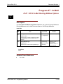
47-01 : IPK II In-Mail System Options ............................................... 2-411
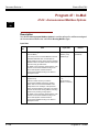
47-02 : IPK II In-Mail Station Mailbox Options ................................... 2-418
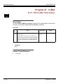
47-03 : IPK II In-Mail Master Mailbox Options ................................... 2-423
47-04 : Master Call Routing Mailbox Options .................................... 2-425
47-05 : Master Announcement Mailbox Options ............................... 2-427
47-06 : Master Subscriber Mailbox Options ...................................... 2-429
47-07 : IPK II In-Mail Routing Mailbox Options .................................. 2-433
47-08 : Call Routing Mailbox Options ................................................ 2-434
47-09 : Announcement Mailbox Options ........................................... 2-436
47-10 : IPK II In-Mail Trunk Options .................................................. 2-438
47-11 : IPK II In-Mail Answer Table Options ..................................... 2-439
47-12 : IPK II In-Mail Answer Schedules ........................................... 2-443
47-13 : IPK II In-Mail Dial Action Tables ............................................ 2-452
47-14 : Master Directory Mailbox Options ........................................ 2-459
47-15 : Routing Directory Mailbox Options ....................................... 2-460
___________________________________________________________________________________
x
Table of Contents
Electra
Elite IPK II
Document Revision 1
___________________________________________________________________________________
Program 50 : Common Channel Interoffice Signaling Service
50-01 : CCIS System Setting ............................................................. 2-461
50-02 : Connecting System Settings ................................................. 2-462
50-03 : CCIS Destination System Settings ........................................ 2-464
50-04 : CCIS Office Code Assignment .............................................. 2-465
50-05 : CCIS Maximum Call Forwarding Hop Counter ...................... 2-466
50-06 : CCIS Feature Availability ....................................................... 2-467
50-07 : CCIS Centralized Billing Center Office .................................. 2-468
50-08 : CCIS Centralized BLF Sending Group Assignment .............. 2-469
50-09 : CCIS Centralized BLF Sending Extension Number
Assignment ............................................................................ 2-470
50-10 : CCIS Centralized BLF Interval Time Assignment .................. 2-472
50-11 : CCIS Centralized Day/Night Switching Sending Group
Assignment ............................................................................ 2-473
50-12 : CCIS Centralized Day/Night Mode to System Mode
Assignment ............................................................................ 2-474
50-13 : CCIS Centralized Response Timeout Assignment ................ 2-475
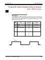
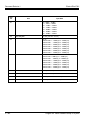
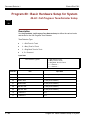
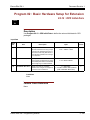
Program 80 : Basic Hardware Setup for System
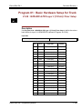
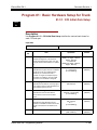
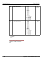
80-01 : Service Tone Setup ............................................................... 2-477
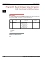
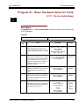
80-02 : DTMF Tone Setup ................................................................. 2-483
80-03 : DTMF Tone Receiver Setup .................................................. 2-485
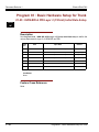
80-04 : Call Progress Tone Detector Setup ....................................... 2-488
80-05 : Date Format for SMDR and System ...................................... 2-490
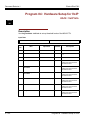
Program 81 : Basic Hardware Setup for Trunk
81-04 : ISDN BRI Layer 1 (T-Point) Initial Data Setup ....................... 2-491
81-05 : ISDN BRI & PRI Layer 2 (T-Point) Initial Data Setup ............ 2-492
81-06 : ISDN BRI & PRI Layer 3 (T-Point) Timer Setup .................... 2-493
81-10 : COI Initial Data Setup ............................................................ 2-495
81-11 : Tie Line Initial Setup .............................................................. 2-497
81-12 : Trunk Gain Level Data Setup ................................................ 2-500
___________________________________________________________________________________
Programming
xi
Document
Revision 1
Electra Elite IPK II
___________________________________________________________________________________
Program 82 : Basic Hardware Setup for Extension
82-01 : Incoming Ring Tone .............................................................. 2-501
82-03 : DSS Console LED Pattern Setup .......................................... 2-503
82-08 : Sidetone Volume Setup ......................................................... 2-505
82-11 : SLI Initial Setup ..................................................................... 2-506
82-12 : OPX Initial Data ..................................................................... 2-507
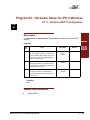
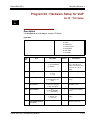
Program 83 : Hardware Setup for IPK II Wireless
83-11 : Wireless DECT Configuration ............................................... 2-509
83-12 : Wireless DECT Measurement ............................................... 2-510
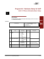
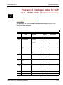
Program 84 : Hardware Setup for VoIP
84-03 : IP Phone Information Basic Setup ........................................ 2-511
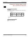
Program 84 : Hardware Setup for VoIP
84-04 : VoIP DHCP Server Mode Setup ........................................... 2-513
84-05 : VoIP IP Address .................................................................... 2-514
84-06 : VoIP Info ................................................................................ 2-516
84-09 : VLAN Setup ........................................................................... 2-518
84-10 : ToS Setup ............................................................................. 2-519
84-11 : Dterm IP CODEC Information Basic Setup ............................ 2-521
84-21 : CCIS over IP CODEC ........................................................... 2-524
Program 85 : HUB(8) LAN Setup
85-01 : HUB(8) LAN Setup ................................................................ 2-527
85-02 : HUB(8) VLAN Setup .............................................................. 2-529
85-03 : Priority Setup ........................................................................ 2-531
85-04 : Port Mirroring Setup .............................................................. 2-533
85-05 : HUB(8) VLAN Group Settings ............................................... 2-534
Program 90 : Maintenance Program
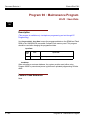
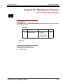
90-01 : Installation Date ..................................................................... 2-537
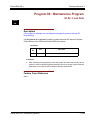
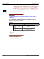
90-02 : Programming Password Setup .............................................. 2-538
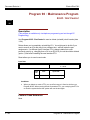
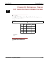
90-03 : Save Data .............................................................................. 2-540
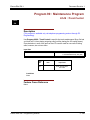
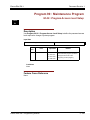
90-04 : Load Data .............................................................................. 2-541
___________________________________________________________________________________
xii
Table of Contents
Electra
Elite IPK II
Document Revision 1
___________________________________________________________________________________
90-05 : Slot Control ............................................................................ 2-542
90-06 : Trunk Control ......................................................................... 2-543
90-07 : Extension Control .................................................................. 2-544
90-08 : System Reset ........................................................................ 2-545
90-09 : Automatic System Reset Time .............................................. 2-546
90-10 : System Alarm Setup .............................................................. 2-547
90-11 : System Alarm Report ............................................................ 2-550
90-12 : System Alarm Output ............................................................ 2-552
90-13 : System Information Output .................................................... 2-553
90-16 : Main Software Information ..................................................... 2-554
90-19 : Dial Block Release ................................................................ 2-555
90-20 : Traffic Report Data Setup ...................................................... 2-556
90-21 : Traffic Report Output ............................................................. 2-557
90-23 : Deleting Registration of IP Telephones ................................. 2-558
90-24 : System Alarm Report Notification Time Setup ...................... 2-559
90-25 : System Alarm Report CC Mail Setup .................................... 2-560
90-26 : Program Access Level Setup ................................................ 2-561
90-27 : Wireless DECT System ID ................................................... 2-562
90-31 : DIM Access over Ethernet .................................................... 2-563
90-34 : Firmware Information ............................................................ 2-564
90-35 : Wizard Programming Level Setup ........................................ 2-565
90-36 : Firmware Update Time Setting ............................................. 2-566
Program 91 : IPK II Wireless DECT PS Entry
91-06 : DECT Obtaining Access Rights ............................................. 2-569
91-07 : DECT Deleting Access Rights ............................................... 2-572
Program 92 : Copy Program
92-01 : Copy Program ....................................................................... 2-573
92-02 : Delete All Extension Numbers ............................................... 2-577
92-03 : Copy Program by Port Number ............................................. 2-578
92-04 : Extension Data Swap ............................................................ 2-579
92-05 : Extension Data Swap Password ........................................... 2-580
___________________________________________________________________________________
Programming
xiii
Document
Revision 1
Electra Elite IPK II
___________________________________________________________________________________
THIS PAGE INTENTIONALLY LEFT BLANK
___________________________________________________________________________________
xiv
Table of Contents
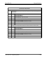
LIST OF TABLES
___________________________________________________________________________________
Table 1-1
Keys for Entering Data ...................................................................................... 1-4
Table 1-2
Keys for Entering Names .................................................................................. 1-5
Table 1-3
Softkey Display Prompts ................................................................................... 1-7
Table 1-4
System Number Plan/Capacities ....................................................................... 1-8
Table 2-1
Programming Modes .................... .................................................................... 2-1
Table 2-2
System Numbering Default Settings ............................................................... 2-33
Table 2-3
Program 15 : 02 – Incoming Signal Frequency Patterns ............................... 2-112
Table 2-4
Program 15 : 08 – Incoming Signal Frequency Patterns ............................... 2-129
Table 2-5
Ringing Cycles .............................................................................................. 2-179
Table 2-6
Program 22 : 03 – Incoming Signal Frequency Patterns ............................... 2-228
Table 2-7
LED Patterns for DSS Console ..................................................................... 2-305
Table 2-8
Basic Tones ................................................................................................... 2-478
___________________________________________________________________________________
Programming
xv
Document
Revision 1
Electra Elite IPK II
___________________________________________________________________________________
THIS PAGE INTENTIONALLY LEFT BLANK
___________________________________________________________________________________
xvi
List of Tables
1
Introduction
SECTION 1
BEFORE YOU START PROGRAMMING
Before customizing your system be sure to read this chapter
first.
This chapter provides you with detailed information about the system
programs. By changing a program, you change the way the feature
associated with that program works. In this chapter, you find out about
each program, the features that the program affects and how to enter the
program data into system memory.
SECTION 2
I
n
t
r
o
d
u
c
t
io
n
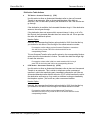
HOW TO USE MANUAL
This section lists each program in numerical order. For example, Program
10-01 is at the beginning of the section and Program 92-01 is at the end.
The information on each program is subdivided into the following
headings:
Description describes what the program options control. The Default
Settings for each program are also included. When you first install the
system, it uses the Default Setting for all programs. Along with the
Description are the Conditions which describe any limits or special
considerations that may apply to the program.
The reverse type (white on black) just beneath the Description heading is
the program’s access level. You can only use the program if your access
level meets or exceeds the level the program requires. Refer to Section 3
How to Enter Programming Mode on page 1-2 for a list of the system
access levels and passwords.
Programming
1-1
Document Revision 1
Electra Elite IPK II
Feature Cross Reference provides you with a table of all the features affected by the
program. You will want to keep the referenced features in mind when you change a
program. Customizing a feature may have an effect on another feature that you did
not intend.
Telephone Programming Instructions shows how to enter the program data into
system memory. For example:
1.
Enter the programming mode.
2.
15-07-01
15-07-01 TEL
KY01 = *01
←
→
tells you to enter the programming mode, dial 150701 from the telephone dial
pad. After you do, you will see the message “15-07-01 TEL” on the first line of
the telephone display. This indicates the program number (15-07), item number
(01), and that the options are being set for the extension . The second row of the
display “KY01 = *01” indicates that Key 01 is being programmed with the entry
of *01. The third row allows you to move the cursor to the left or right, depending
on which arrow is pressed. To learn how to enter the programming mode, refer
to Section 3 How to Enter Programming Mode below.
SECTION 3
HOW TO ENTER PROGRAMMING MODE
To enter programming mode:
1.
Go to any working display telephone.
In a newly installed system, use extension (port 1).
2.
Do not lift the handset.
3.
Press Speaker.
4.
#,#,.
Password
5.
1-2
Dial the system password + Transfer.
Refer to the following table for the default system passwords. To change the
passwords, use 90-02 : Programming Password Setup.
Introduction
Electra Elite IPK II
Document Revision 1
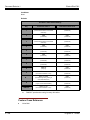
Password
User
Name
Level
47544
necii
1 (MF)
Programs at this Level
Manufacturer (MF):
All programs
12345678
tech
2 (IN)
Installation (IN):
All programs in this section not listed below for SA and
SB
0000
ADMIN1
3 (SA)
System Administrator - Level 1 (SA):
10-01, 10-02, 10-12, 10-13, 10-14, 10-15, 10-16, 10-17,
10-18, 10-22, 12-02, 12-03, 12-04, 15-01, 15-07, 15-09,
15-10, 15-11, 20-16, 21-07, 21-14, 22-04, 22-11, 25-08,
30-03, 32-02, 40-02, 41-02, 41-03, 41-04, 41-05, 41-06,
41-07, 41-08, 41-09, 41-10, 41-11, 41-12, 41-13, 41-14,
41-15, 41-16, 41-17, 41-18, 90-03, 90-04, 90-06, 90-07,
90-18, 90-19
9999
ADMIN2
4 (SB)
System Administrator - Level 2 (SB):
13-04, 13-05, 13-06
SECTION 4
HOW TO EXIT PROGRAMMING MODE
To exit the programming mode:
When you are done programming, you must be out of a program’s options to exit
(pressing the Answer key will exit the program’s option).
1.
Press Answer key to exit the program’s options, if needed.
Program Mode
Base Service OP1 OP2
2.
Press Speaker. If changes were to the system programming, "Saving System
Data" is displayed.
3.
The display shows "Complete Data Save" when completed and exits the
telephone to an idle mode.
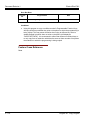
Programming
To save a customer’s database, a blank Compact Flash (CF) is required. Insert the CF
into the CPUII and, using Program 90-03, save the software to the Compact Flash.
(Program 90-04 is used to reload the customer data if necessary.) Note that a Compact
Flash can only hold one customer database. Each database to be saved will require its
own separate card.
1-3
Document Revision 1
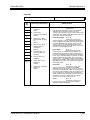
SECTION 5
Electra Elite IPK II
USING KEYS TO MOVE AROUND IN THE PROGRAMS
Once you enter the programming mode, use the keys in the following chart to enter
data, edit data and move around in the menus.
Table 1-1 Keys for Entering Data
Keys for Entering Data
Use this key...
0~9 and ,
TRANSFER
When you want to...
Enter data into a program.
Complete the programming step you just made (e.g., pressing Enter
on a PC keyboard). When a program entry displays, press
TRANSFER to bypass the entry without changing it.
CONF
Delete the entry to the left (e.g., pressing Backspace on a PC
keyboard).
HOLD
Delete or clear all characters to the right of the cursor.
ANSWER
Exit one step at a time from the program window currently being
viewed.
For example, if programming item 5 in 15-03, pressing ANSWER
allows you to enter a new option in program 15-03. Pressing
ANSWER again allows you to select a new program in the 15-XX
series. Pressing ANSWER a third time allows you to enter a new
program beginning with 1. Pressing ANSWER one last time brings
you to the beginning program display, allowing you to enter any
program number.
REDIAL
Switch between the different input data fields by pressing REDIAL.
The cursor moves up to the top row of the display. Pressing REDIAL
again moves the cursor back to the middle row.
LINE KEYS
Use pre-programmed settings to help with the program entry. These
settings vary between programs from LINE 1 = 0 (off) and LINE 2 = 1
(on) to preset values for timers where LINE 1 = 5, LINE 2 = 10, LINE
3 = 15, etc.
For programs with this option, the line key, which currently matches
the programmed setting, lights steady.
The display can also indicate Softkey, which will allow you to select
the values as well (-1 and +1 will step through these pre-programmed
settings.)
1-4
LINE KEY 1
Program a pause into an Speed Dialing bin.
LINE KEY 2
Program a recall/flash into an Speed Dialing bin.
LINE KEY 3
Program an @ into an Speed Dialing bin.
Introduction
Electra Elite IPK II
Document Revision 1
Table 1-1 Keys for Entering Data (Continued)
Keys for Entering Data
Use this key...
VOL
VOL
L
M
When you want to...
Scroll backward through a list of entry numbers (e.g., from extension
etc.) or through entries in a table (e.g., Common Permit Table).
If you enter data and then press this key, the system accepts the data
before scrolling forward.
Scroll forward through a list of entry numbers (e.g., from extension
etc.) or through entries in a table (e.g., Common Permit Table).
If you enter data and then press this key, the system accepts the data
before scrolling backward.
SECTION 6
PROGRAMMING NAMES AND TEXT MESSAGES
Several programs (e.g., Program 20-16 : Selectable Display Messages) require you
to enter text. Use the following chart when entering and editing text. When using the
keypad digits, press the key once for the first character, twice for the second
character, etc. For example, to enter a C, press the key 2 three times. Press the key
six times to display the lower case letter. The name can be up to 12 digits long.
Table 1-2 Keys for Entering Names
Use this keypad digit . . .
1
When you want to. . .
Enter characters:
1 @ [ ¥ ] ^ _ ` { | }
2
Enter characters A-C, a-c, 2.
3
Enter characters D-F, d-f, 3.
4
Enter characters G-I, g-i, 4.
5
Enter characters J-L, j-l, 5.
6
Enter characters M-O, m-o, 6.
7
Enter characters P-S, p-s, 7.
8
Enter characters T-V, t-v, 8.
9
Enter characters W-Z, w-z, 9.
0
Enter characters:
0
Programming
Æ ¨ Á À Â Ã Ç É Ê ì ó
!
“
#
$
%
&
’
(
) ô Õ ú ä ö ü
α ε θ
1-5
Document Revision 1
Electra Elite IPK II
Table 1-2 Keys for Entering Names
Use this keypad digit . . .
,
When you want to. . .
Enter characters:
, + , - . / : ; < = > ?
#
SECTION 7
B E σ S
∞ ¢ £
# = Accepts an entry (only required if two letters on the same
key are needed - ex: TOM). Pressing # again = Space. (In
system programming mode, use the right arrow Softkey
instead to accept and/or add a space.)
CONF
Clear the character entry one character at a time.
HOLD
Clear all the entries from the point of the flashing cursor and to
the right.
USING SOFTKEYS FOR PROGRAMMING
Each Electra Elite IPK II display telephone provides interactive Softkeys for intuitive
feature access. The options for these keys will automatically change depending on
where you are in the system programming. Simply press the Softkey located below
the option you wish and the display will change accordingly.
_
Base
Program Mode
Service
OP1
Pressing the VOLUME
OP2
L or VOLUME M
will scroll between the menus.
_
CCIS
1-6
Program Mode
Hard Mtnance
Introduction
Electra Elite IPK II
SECTION 8
Document Revision 1
WHAT THE SOFTKEY DISPLAY PROMPTS MEAN
When using a display telephone in programming mode, various Softkey options are
displayed. These keys will allow you to easily select, scan, or move through the
programs.
Table 1-3 Softkey Display Prompts
Softkey Display Prompts
If you press this
Softkey . . .
back
The system will. . .
Go back one step in the program display.
L
You can press VOLUME
or VOLUME
backward through a list of programs.
↑
Scroll down through the available programs.
↓
Scroll up through the available programs.
select
Programming
M to scroll forward or
Select the currently displayed program.
←
Move the cursor to the left.
→
Move the cursor to the right.
-1
Move back through the available program options.
+1
Move forward through the available program options.
1-7
Document Revision 1
SECTION 9
Electra Elite IPK II
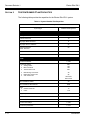
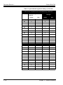
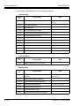
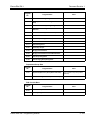
SYSTEM NUMBER PLAN/CAPACITIES
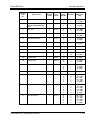
The following table provides the capacities for the Electra Elite IPK II system.
Table 1-4 System Number Plan/Capacities
System Number Plan/Capacities
System Type
Number Plan/Capacities
System
Analog Caller ID Detector
64
Classes of Service
15
Day/Night Mode Numbers
8
Day/Night Service Patterns
32
Dial Tone Detector
DTMF Receiver
64
Toll Restriction Classes
15
Verifiable Account Code Table
2000
Trunk
Trunk Port Number
Trunk Ports (Total):
H Analog Trunks
H BRI Trunk Ports
H T1/PRI Trunk Ports
H
H
H
E&M Analog Trunk Ports
DID Analog Trunk Ports
VoIP Trunk Ports
DID Translation Tables
DID Translation Table Entries
1~200
200
184
184
200
46
92
184 if IAD
200 is PVA
20
2000
DISA:
H
H
Classes of Service
Users
Ring Groups
1-8
15
1~15
1~100
Tie Line Classes of Service
15
Tie Line Toll Restriction Classes
15
Trunk Access Maps
1~200
Trunk Group Numbers
1~100
Introduction
Electra Elite IPK II
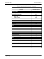
Document Revision 1
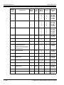
Table 1-4 System Number Plan/Capacities (Continued)
System Number Plan/Capacities
System Type
Trunk Routes
Number Plan/Capacities
1~100
Extension
Telephone Extension Port Numbers
H Multiline Terminals
H Single Line Phones/Analog Devices
H VoIP Extensions
H Electra Elite IPK II Wireless
1~256
(1~240)
(1~184)
(1~256)
256
Extension Ports (Total):
H Multiline Terminals
H Single Line Phones/Analog Devices
240
184
ESIU:
H
Physical Ports
01~16
Physical Ports
01~16
SLIU:
H
Telephone Extension Number Range
Virtual Extension Ports
Virtual Extension Port Numbers
Virtual Extension Number Range
256
001~256
Undefined
PGD(2)-U10 Modules
56
ADA (Recording Jack) Adapters
240
Electra Elite IPK II Wireless DECT Base Stations
16
Electra Elite IPK II Wireless DECT Telephones
256
Door Boxes
Programming
1~99999999
8
Door Box Numbers
1~8
DSS Consoles Numbers:
H 60 Button DSS Console
32
Operator Access Number
0
Operator Extension
1
Ringdown Assignments
512
SLT Adapters
16
HF-R Adapters
240
1-9
Document Revision 1
Electra Elite IPK II
Table 1-4 System Number Plan/Capacities (Continued)
System Number Plan/Capacities
System Type
Number Plan/Capacities
Speed Dialing
Speed Dialing Groups
Speed Dialing Bins
Speed Dialing Table-Common
64
0~1999
1000
ACD
ACD Groups
64
ACD Agent Extensions
256
ACI
ACI Groups
16
ACI Ports
96
Automated Attendant
VRS Message Numbers
1~48
Conference
Conference Circuits
64 - maximum
(32 Parties Per Conference)
Data Communication Interfaces
APR Software Port Numbers
193~256
APA Adapters
240
APR Adapters
240
CTA or CTU Adapters
32
Department and Pickup Groups
Department (Extension) Group Numbers
1~64
Call Pickup Group Numbers
1~64
Hotline
1 - 10
Internal Hotline
512
External Hotline
512
Introduction
Electra Elite IPK II
Document Revision 1
Table 1-4 System Number Plan/Capacities (Continued)
System Number Plan/Capacities
System Type
Number Plan/Capacities
Paging and Park
Internal Page Group Numbers
0, 1~9 or 01~64
External Page Group Numbers
0, 1~8
External Speakers
H CPU II( )-U10
H PGD(2)-U10 Module
9
(1)
(1~8)
Park Group Numbers
1~64
Park Orbits
1~64
SMDR
SMDR Ports
1~8
VRS
VRS (on DSP Daughter Board)
1
VRS Channels
16
VRS Attendant Messages
3
VRS Recordable Messages
48
Voice Mail
Ports for IPK II In-Mail
8
Ports for External Voice Mail
48
VoIP
Programming
ADA2 (Recording Jack) Adapters
240
IP Adapters
256
PSA (Power Failure) Adapters
256
RTP Ports
0~65535
RTCP Ports
0~65535
DSP Resources
01~208
1 - 11
Document Revision 1
Electra Elite IPK II
Table 1-4 System Number Plan/Capacities (Continued)
System Number Plan/Capacities
System Type
Number Plan/Capacities
Passwords
Programming Passwords:
Level 1 (MF)
PCPro/WebPro User Name:
47544
necii
Level 2 (IN)
PCPro/WebPro User Name:
12345678
tech
Level 3 (SA)
PCPro/WebPro User Name:
0000
ADMIN1
Level 4 (SB)
PCPro/WebPro User Name:
9999
ADMIN2
Programming Password Users
8
Footnotes
Extension numbers can be one to eight digits long. Refer to the Flexible System Numbering
feature in the Electra Elite IPK II Features and Specifications manual.
1 - 12
Introduction
Programming the Electra Elite IPK II
SECTION 1
2
PROGRAMMING YOUR SYSTEM
The information contained in this chapter provides the information
necessary to properly program your Electra Elite IPK II system.
The programming blocks are organized into the following programming
modes.
Table 2-1 Programming Modes
Program Number : Program Name
Program 10 : System Configuration Setup
Pr
og
ra
m
m
in
g
Program 11 : System Numbering
Program 12 : Night Mode Setup
Program 13 : Speed Dialing
Program 14 : Trunk, Basic Setup
Program 15 : Extension, Basic Setup
Program 16 : Department Group Setup
Program 20 : System Option Setup
Program 21 : Outgoing Call Setup
Program 22 : Incoming Call Setup
Program 23 : Answer Features Setup
Program 24 : Hold/Transfer Setup
Program 25 : DID/DISA Setup
Program 26 : ARS Service
Program 30 : DSS/DLS Console Setup (no Programs 27~29)
Program 31 : Paging Setup
Programming
2-1
Document Revision 1
Electra Elite IPK II
Table 2-1 Programming Modes (Continued)
Program Number : Program Name
Program 32 : Door Box and Sensor Setup
Program 33 : CTA and ACI Setup
Program 34 : Tie Line Setup
Program 35 : SMDR Account Code Setup
Program 40 : Voice Recording System (no Programs 36~39)
Program 41 : ACD Setup
Program 42 : Hotel Setup
Program 44 : ARS/F-Route Setup (no Program 43)
Program 45 : Voice Mail Integration
Program 47 : In-Mail (no Program 46)
Program 50 : Common Channel Interoffice Signaling Service (CCIS)
Program 80 : Basic Hardware Setup for System (no Programs 48, 49, 51~79)
Program 81 : Basic Hardware Setup for Trunk
Program 82 : Basic Hardware Setup for Extension
Program 83 : Hardware Setup for IPK II Wireless
Program 84 : Hardware Setup for VoIP
Program 85 : HUB(8) LAN Setup
Program 90 : Maintenance Program (no Programs 86~89)
Program 91 : IPK II Wireless DECT PS Entry
Program 92 : Copy Program
2-2
Programming the Electra Elite IPK II
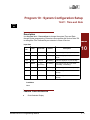
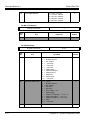
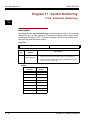
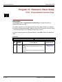
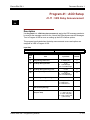
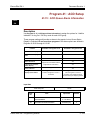
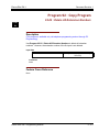
Program 10 : System Configuration Setup
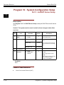
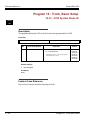
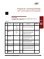
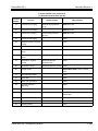
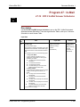
10-01 : Time and Date
Level:
SA
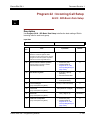
Description
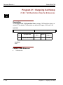
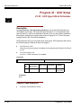
Use Program 10-01 : Time and Date to change the system Time and Date
through system programming. Extension users can also dial Service Code 728
to change the Time if allowed by an extension’s Class of Service.
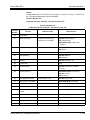
Program
Input Data
Item
No.
Item
Input Data
Default
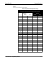
01
Year
00~99
No Setting
Enter two digits for year (00~99).
02
Month
01~12
No Setting
Enter two digits (01~12) for the
month.
03
Day
01~31
No Setting
Enter two digits (01~31) for the day.
04
Week
1~7
(Sun~Sat)
No Setting
Enter digit for the day of the week
(1=Sunday, 7=Saturday).
05
Hour
00~23
No Setting
Enter two digits for the hour (00~23).
06
Minute
00~59
No Setting
Enter two digits for the minute
(00~59).
07
Second
00~59
No Setting
Enter two digits for the second
(00~59).
Description
10
Conditions
None
Feature Cross Reference
J
Clock/Calendar Display
Electra Elite IPK II Programming Manual
2-3
Document Revision 1
Electra Elite IPK II
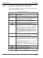
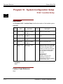
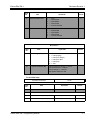
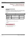
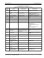
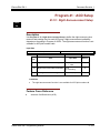
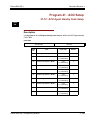
Program 10 : System Configuration Setup
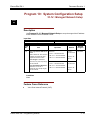
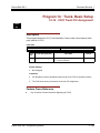
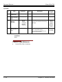
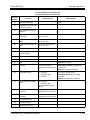
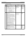
10-02 : Location Setup
Level:
SA
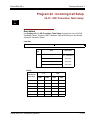
Description
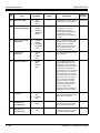
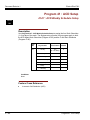
Use Program 10-02 : Location Setup to define the location of the installed system.
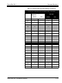
Input Data
Item
No.
Item
Input Data
Default
Description
01
Country Code
Dial (up to 4 digits)
0~9, ,, #
1
Enter the country code.
02
International
Access Code
Dial (up to 4 digits)
0~9, ,, #
-
Enter the international access
code.
03
Other Area
Access Code
Dial (up to 2 digits)
0~9, ,, #
9
Enter the other area access code
04
Area Code
Dial (up to 6 digits)
0~9, ,, #
-
Enter the local area code.
05
Trunk Access
Code
Dial (up to 8 digits):
0~9, #, ,
-
Enter the trunk access code digits
required to place an outgoing call.
This is the code which will be
added to the Caller ID information
for incoming trunk calls to allow
the call to dial out if allowed in
20-19-03.
IMPORTANT
Program 10-02-05 is only
supported by telephone
programming. PCPro and WebPro
cannot edit this option.
Conditions
None
Feature Cross Reference
None
2-4
Program 10 : System Configuration Setup
Electra Elite IPK II
Document Revision 1
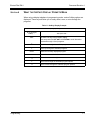
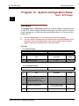
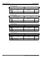
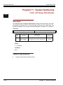
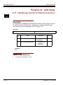
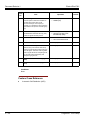
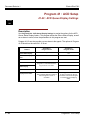
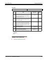
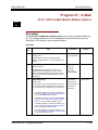
Program 10 : System Configuration Setup
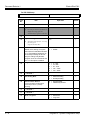
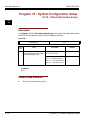
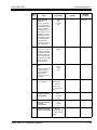
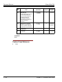
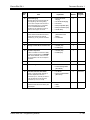
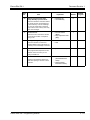
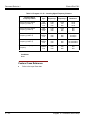
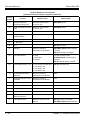
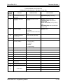
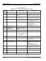
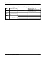
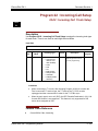
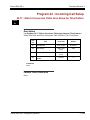
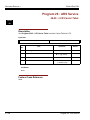
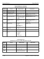
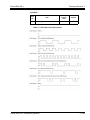
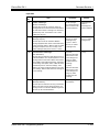
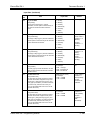
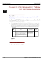
10-03 : ETU Setup
Level:
IN
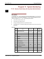
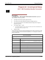
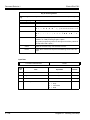
Description
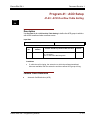
Use Program 10-03 : ETU Setup to setup and confirm the Basic Configuration data
for each ETU. When changing a defined terminal type, first set the type to ‘0’ and then
plug the new device in to have the system automatically define it or you may have to
reseat the ETU.
The items highlighted in gray are read only and cannot be changed.
The item numbers indicated below are different when using PCPro/WebPro due to
the window layout of the applications. Refer to the program within the PCPro/
WebPro application to determine the correct item number.
Input Data
For CNF PKG Setup
Physical Port Number
Item
No.
01
Item
Logical Port Number
01~16
Input Data
Default
0~256
0
For CCISoIP PKG Setup
Physical Port Number
Item
No.
01
Item
Logical Port Number
01~24
Input Data
Default
0~200
0
0 = D4 (12 Multi Frame)
1 = ESF (24 Multi Frame)
1
The start port number of a T1 line is
displayed. 24 logic ports are
automatically assigned to a DTI (T1)
line.
02
T1 Signal Format Selection
03
Clear Channel Selection
Electra Elite IPK II Programming Manual
0
2-5
Document Revision 1
Electra Elite IPK II
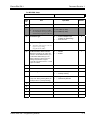
04
0 = 0 feet ~ 133 feet
1 = 134 feet ~ 266 feet
2 = 267 feet ~ 399 feet
3 = 400 feet ~ 533 feet
4 = 534 feet ~ 655 feet
Line Length Selection
0
For MG 16 PKG Setup
Physical Port Number
Item
No.
01
0
Item
Logical Port Number
Input Data
Default
0~256
0
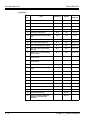
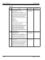
For ESI PKG Setup
Physical Port Number
Item
No.
2-6
01~16
Item
Input Data
Default
01
Terminal Type (B1)
0
1
2
3
4
5
6
7
8
9
10
11
=
=
=
=
=
=
=
=
=
=
=
=
Not set
Multiline Terminal
SLT Adapter
-- Not Used --- Not Used --- Not Used -PGD (Paging)
PGD (Tone Ringer)
PGD (Doorbox)
PGD (ACI)
DSS Console
-- Not Used --
0
02
Logical Port Number (B1)
0
1
2
3
4
5
6
7
8
9
10
11
=
=
=
=
=
=
=
=
=
=
=
=
Not set
Multiline Terminal
SLT Adapter
Not Used
Not Used
2DCI Adapter 1~32
PGD (Paging)
PGD (for Tone Ringer) 1~4 or 1~8
PGD (for Door Box) 1~4 or 1~8
PGD (for Analog I/F) 1~8 or 1~96
DSS
-- Not Used --
0
03
--- Not Used ---
Program 10 : System Configuration Setup
Electra Elite IPK II
Document Revision 1
Item
No.
Item
Input Data
Default
04
Optional Installed Unit 1
0
1
2
3
4
=
=
=
=
=
None
APR Module
APA Module
ADA Module
CTA/CTU Module
0
05
Optional Installed Unit 2
0
1
2
3
4
=
=
=
=
=
None
APR Module
APA Module
ADA Module
CTA/CTU Module
0
B-Channel 2
Item
No.
Item
Input Data
Default
0
06
Terminal Type (B2)
0
6
7
8
9
12
07
Logical Port Number (B2)
PGD (Paging/Tone Ringer) = 1-PGmax
PGD (for Door Box) = 1-DBmax
PGD (Analog I/F) = 1-ACImax
APR (for B2 mode) 193~256
=
=
=
=
=
=
Not set
PGD (Paging)
PGD (Tone Ringer)
PGD (Door Box)
PGD (ACI)
APR
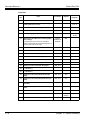
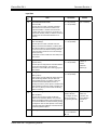
For SLI PKG Setup
Physical Port Number
Item
No.
Item
01~08
Input Data
Default
0~256
0
01
Logical Port Number
02
--- Not Used ---
03
Transmit Gain Level (S-Level)
1~63 (-15.5 +15.5dB)
32 (0dB)
04
Receive Gain Level (R-Level)
1~63 (-15.5 +15.5dB)
32 (0dB)
Electra Elite IPK II Programming Manual
2-7
Document Revision 1
Electra Elite IPK II
For COIU Unit Setup
Physical Port Number
Item
No.
01
Item
Logical Port Number
01~08
Input Data
Default
0~200
0
For TLI PKG Setup
Physical Port Number
Item
No.
01
Item
Logical Port Number
01~02
Input Data
Default
0~200
0
For DID PKG Setup
Physical Port Number
Item
No.
01
Item
Logical Port Number
01~04
Input Data
Default
0~200
0
For OPX PKG Setup
Physical Port Number
Item
No.
01
2-8
Item
Logical Port Number
01~08
Input Data
Default
0~256
0
Program 10 : System Configuration Setup
Electra Elite IPK II
Document Revision 1
For BRI PKG Setup
ISDN Line Number
Item
No
Item
01
--- Not Used ---
02
Logical Port Number
03
01~08
The starting port number of a BRI
line is displayed. Two logic ports are
automatically assigned to a BRI line.
Connection Type
Input Data
0 = Net Set
1 = For T-Bus (1~200)
2 = For S-Bus (1~256)
0
0
0
1
04
05
Layer 3 Timer Type
Default
= Point-to-Multipoint (not
available for Networking)
= Point-to-Point
1~5
1
0
1
= Disable
= Enable
1
1
Each timer value of Layer 3 are set
up for every type using
Program 81-06 (T-Bus)
CLIP Information Announcement
Based on this setting, the system will
include a “Presentation Allowed” (1) or
“Presentation Restricted” (0) in the
Setup message to allow or deny the
Calling Party Number. Program
15-01-04 must also be set to a ‘1’ if this
option is enabled.
06
--- Not Used ---
07
--- Not Used ---
08
Dial Sending Mode
0
1
= Enblock Sending
= Overlap Sending
09
Dial Information Element
0
1
= Keypad Facility
= Called Party Number
(Only when Dialing Sending Mode (1003-08) is set for 1 (Overlap Sending)
10
--- Not Used ---
11
--- Not Used ---
12
--- Not Used ---
13
--- Not Used ---
14
--- Not Used ---
Electra Elite IPK II Programming Manual
2-9
Document Revision 1
Electra Elite IPK II
For PRI PKG Setup
ISDN Line Number
Item
No.
Item
01
--- Not Used ---
02
Logical Port Number
--- Not Used ---
04
Layer 3 Timer Type
1
= for T-Bus
1~200
Default
1
1~5
1
0
1
= Disable
= Enable
1
0
1
2
3
4
=
=
=
=
=
0
Each timer value of Layer 3 is set up
for each type in
Program 81-06 (T-Bus)
CLIP Information
Based on this setting, the system
will include a “Presentation Allowed”
(1) or “Presentation Restricted” (0)
in the Setup message to allow or
deny the Calling Party Number.
Program 15-01-04 must also be set
to a ‘1’ if this option is enabled.
06
Length of Cable
07
--- Not Used ---
08
Dial Sending Mode
0
1
= Enblock Sending
= Overlap Sending
09
Dial Information Element
0
1
= Keypad Facility
= Called Party Number
0
1
= Short-Haul
= Long-Haul
(Only when Dialing Sending Mode
(10-03-08) is set for 1 (Overlap
Sending)
2 - 10
Input Data
The start port number of a PRI line is
displayed. 24 logic ports are
automatically assigned to a PRI line.
03
05
01~24
10
--- Not Used ---
11
--- Not Used ---
12
Short / Long-Haul
0 ~ 40m
41~ 80m
81~ 121m
122 ~ 162m
163 ~ 200m
1
0
Program 10 : System Configuration Setup
Electra Elite IPK II
Document Revision 1
Item
No.
13
Item
Loss-Of-Signal Detection Limit
Input Data
In Short-Haul Mode:
0 = 0.91V
1 = 0.74V
2 = 0.59V
3 = 0.42V
4 = 0.32V
5 = 0.21V
6 = 0.16V
7 = 0.10V
Default
0
In Long-Haul Mode:
0 = 1.70V
1 = 0.84V
2 = 0.84V
3 = 0.45V
4 = 0.45V
5 = 0.20V
6 = 0.10V
7 = Not Defined
14
--- Not Used ---
For DTI (T1) PKG Setup
Physical Port Number
Item
No.
01
01~24
Item
Logical Port Number
Input Data
Default
0~200
0
The start port number of a T1 line is
displayed. 24 logic ports are
automatically assigned to a DTI (T1)
line.
02
T1 Signal Format Selection
03
Clear Channel Selection
04
Line Length Selection
Electra Elite IPK II Programming Manual
0
1
= D4 (12 Multi Frame)
= ESF (24 Multi Frame)
1
0
0
1
2
3
4
=
=
=
=
=
0 feet ~ 133 feet
134 feet ~ 266 feet
267 feet ~ 399 feet
400 feet ~ 533 feet
534 feet ~ 655 feet
0
2 - 11
Document Revision 1
Electra Elite IPK II
05
DTI Trunk Type Assignment
0
1
2
3
=
=
=
=
CO
E&M
DID
ANI
0
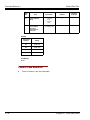
For VMS/FMS PKG Setup
Physical Port Number
Item
No.
01
Item
Logical Port Number
01~16
Input Data
Default
0~256
0
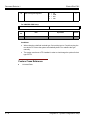
Conditions
H When changing a defined terminal type, first set the type to ‘0’ and then plug the
new device in to have the system automatically define it or redefine the type
manually.
H The system must have a ETU installed in order to view/change the options for that
type of ETU.
Feature Cross Reference
J
2 - 12
Universal Slots
Program 10 : System Configuration Setup
Electra Elite IPK II
Document Revision 1
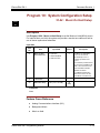
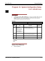
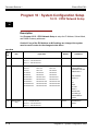
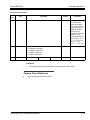
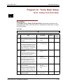
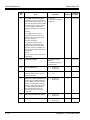
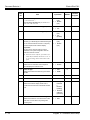
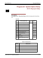
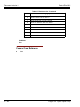
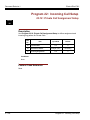
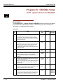
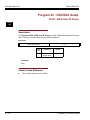
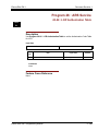
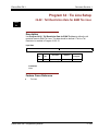
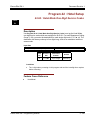
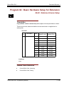
Program 10 : System Configuration Setup
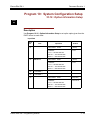
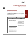
10-04 : Music On Hold Setup
Level:
IN
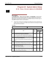
Description
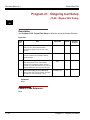
Use Program 10-04 : Music on Hold Setup to set the Music on Hold (MOH) source.
For internal Music on Hold, the system can provide a service tone callers on hold or
one of eleven synthesized selections.
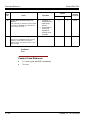
Input Data
Item
No.
01
Item
Music on Hold
Source Selection
Input Data
0 = No Tone
1 = External MOH
2 = Service Tone
Default
2
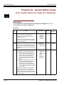
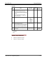
Description
The Music on Hold (MOH)
source can be internal
(synthesized) or from a
customer-provided music
source.
The customer-provided source
can connect to a PGD(2)-U10
ADP or the connector on the
side of the Base Cabinet’s
MOH/IN connection.
Trunk MOH and Extension
MOH music source use the
same Music on Hold source.
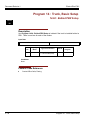
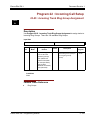
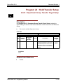
02
--- Not Used ---
03
Audio Gain Setup
1-63 (-15.5 +15.5dB)
32
(0dB)
Conditions
None
Feature Cross Reference
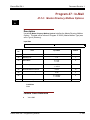
J
Analog Communications Interface (ACI)
J
Background Music
J
Music on Hold
Electra Elite IPK II Programming Manual
2 - 13
Document Revision 1
Electra Elite IPK II
Program 10 : System Configuration Setup
10-05 : General Purpose Relay Setup
Level:
IN
Description
Use Program 10-05 : General Purpose Relay Setup to define which Relay circuits
(5~8) on PGD(2)-U10 Adapter are used for General Purpose Relay.
Input Data
- INDEX-1 General Purpose Relay No.
Item
No.
01
1~8
Item
Slot No.
Physical Port of ESIU
Sensor circuit No.
Input Data
Slot No: 0~16
ESIU Port: 0~16
Relay No: 0, 5~8
Default
0-0-0
After each entry,
pressing the
Transfer Key will
advance to the
next entry.
Conditions
None
Feature Cross Reference
J
2 - 14
Analog Communications Interface (ACI)
Program 10 : System Configuration Setup
Electra Elite IPK II
Document Revision 1
Program 10 : System Configuration Setup
10-06 : ISDN BRI Setup
Level:
IN
Description
J
Use Program 10-06 : ISDN - BRI Setup to configure the ISDN - BRI’s Terminal
Endpoint Identifier (TEI), mode of operation, and Service Profile Identifier
(SPID) number for each circuit’s B-Channels.
Input Data
ISDN - BRI Circuit
Item
No.
01
Item
TEI Selection
Selects the method the
system will use when
assigning Terminal
Endpoint Identifier (TEI)
values to BRI ports.
1~4
Input Data
Default
0 = Select by SPID number
1 = Route by Redirecting Number
0
0
02
DID Mode
0 = Route by Called Party Number
1 = Route by Redirecting Number
03
SPID 1
Dial up to 20 digits
04
SPID 2
Dial up to 20 digits
Conditions
None
Feature Cross Reference
J
ISDN Compatibility
Electra Elite IPK II Programming Manual
2 - 15
Document Revision 1
Electra Elite IPK II
Program 10 : System Configuration Setup
10-08 : Ringing Setup
Level:
IN
Description
Use Program 10-08 : Ringing Setup to enable or disable pre-ringing for trunk calls.
This sets how a trunk initially rings a telephone. With pre-ringing, a burst of ringing
occurs as soon as the trunk’s LED flashes. The call then continues ringing with the
normal ring cadence cycle. Without pre-ringing, the call starts ringing only when the
normal ring cadence cycle occurs. This may cause a ring delay, depending on when
call detection occurs in reference to the ring cycle.
Input Data
Item
No.
01
Description
Ringing Setup
Input Data
Default
0 = Disable
1 = Enable
0
Conditions
H Used with Analog Trunks only.
Feature Cross Reference
J
J
2 - 16
Central Office Calls, Answering
Synchronous Ringing
Program 10 : System Configuration Setup
Electra Elite IPK II
Document Revision 1
Program 10 : System Configuration Setup
10-09 : DTMF and Dial Tone Circuit Setup
Level:
IN
Description
Use Program 10-09 : DTMF and Dial Tone Circuit Setup to allocate the circuits on
the CPUII for either DTMF receiving or dial tone detection. The CPUII has 16 circuits
initially. On the Electra Elite IPK II, with additional PGD(2)-U10 ADPs installed, the
system can provide a total of 64 circuits (32 + 32). These are used as follows:
J
J
Extension
DTMF receiver for single line telephone
Trunk
DTMF receiver for analog trunks, dial tone & busy tone detection
for analog trunks
Input Data
Circuit/Resource Number
Item
No.
01
01~64
Input Data
0 = Common Use
1 = Extension Only
2 = Trunk Only
Default Setting
Circuit/Resource 01-08: 1 (Extension Only)
Circuit/Resource 09-32: 2 (Trunk Only)
Circuit/Resource 33-64: 0 (Common Use)
Conditions
None
Feature Cross Reference
J
J
J
J
J
Caller ID
Central Office Calls, Placing
Direct Inward Dialing (DID)
Direct Inward System Access (DISA)
Tie Lines
Electra Elite IPK II Programming Manual
2 - 17
Document Revision 1
Electra Elite IPK II
Program 10 : System Configuration Setup
10-12 : CPUII Network Setup
Level:
SA
Description
Use Program 10-12 : CPUII Network Setup to setup the IP Address, Subnet-Mask,
and Default Gateway addresses.
Caution! If any of the IPK Address or NIC settings are changed, the system
must be reset in order for the changes to take affect.
Input Data
Item
No.
Item
01
IP Address
Input Data
Default
Conditions
172.16.0.10
1.0.0.1 ~ 126.255.255.254
128.1.0.1 ~ 191.254.255.254
192.0.1.1 ~ 223.255.254.254
02
03
Subnet Mask
Default Gateway
128.0.0.0
192.0.0.0
224.0.0.0
240.0.0.0
248.0.0.0
252.0.0.0
254.0.0.0
255.0.0.0
255.128.0.0
255.192.0.0
255.224.0.0
255.248.0.0
255.252.0.0
255.254.0.0
255.255.0.0
255.255.128.0
255.255.192.0
255.255.224.0
255.255.248.0
255.255.252.0
255.255.254.0
255.255.255.0
255.255.255.128
255.255.255.192
255.255.255.224
255.255.255.240
255.255.255.248
255.255.255.252
255.255.255.254
255.255.255.255
1.0.0.1 ~ 126.255.255.254
128.1.0.1 ~ 191.254.255.254
255.255.0.0
The setting of
Subnet-Mask is
invalid when all Host
Address are 0.
If the network
section is:
0,
127
128.0
191.255
192.0.0
223.255.255
The setting of
Subnet-Mask is
invalid.
0.0.0.0
IP Address for
Router.
192.0.1.1 ~ 223.255.254.254
2 - 18
Program 10 : System Configuration Setup
Electra Elite IPK II
Document Revision 1
Input Data (Continued)
Item
No.
Item
04
Time Zone
05
NIC Interface
08
--- Not Used ---
Input Data
0~24 (0 = -12 Hours and 24 = +12 Hours)
0 = Auto Detect
1 = 100Mbps, Full Duplex
2 = 100Mbps, Half Duplex
3 = 10Mbps, Full Duplex
4 = 10Mbps, Half Duplex
Default
Conditions
+7 Hours
Determine the offset
from Greenwich
Mean Time (GMT)
time. Then enter its
respective value. For
example, Eastern
Time (US and
Canada) has a GMT
offset of -5. The
program data would
then be 7 (0= -12, 1=
-11, 2= -10, 3= -9, 4=
-8, 5= -7, 6= -6,
7= -5, ……24= +12)
0
NIC Auto Negotiate
Conditions
H The system must be reset in order for these changes to take affect.
Feature Cross Reference
J
Voice Over Internet Protocol (VoIP)
Electra Elite IPK II Programming Manual
2 - 19
Document Revision 1
Electra Elite IPK II
Program 10 : System Configuration Setup
10-13 : In-DHCP Server Setup
Level:
SA
Description
Use Program 10-13 : In-DHCP Server Setup to setup the DHCP Server built into the
CPUII.
Caution! The system must be reset in order for these changes to take affect.
Input Data
Item
No.
Item
Input Data
Default
Description
01
DHCP Server
Mode
0: Disable
1: Enable
0
02
Lease Time
Days 0~255
0 day
Lease Time of the IP address to a
client.
Hour 0~23
0 hour
Note: Pressing the Transfer Key
will increment to the next setting
data.
Minutes 1~59
03
--- Not Used ---
04
Number of
Networks
0: Single
1: Divide Same
Network
Enable or disable the use of the
built-in DHCP Server.
30 minutes
0
The number of networks to
manage.
With a single network, select
Single.
When dividing and managing the
same network as multiple
networks, select Divide.
Conditions
None
Feature Cross Reference
J
2 - 20
Voice Over Internet Protocol (VoIP)
Program 10 : System Configuration Setup
Electra Elite IPK II
Document Revision 1
Program 10 : System Configuration Setup
10-14 : Managed Network Setup
Level:
SA
Description
Use Program 10-14 : Managed Network Setup to set up the range of the IP address
which the DHCP Server leases to a client.
Input Data
Scope Number
1~10
Item
No.
Item
01
The range of the IP address to
lease.
Minimum:
When “Maximum” has not been
entered, the maximum value
equals the minimum value.
128.1.0.1 ~ 191.254.255.254
When Single is selected in
10-13-04, only one scope range
can be entered.
When Divide Same Network is
selected in 10-13-04, a
maximum of ten scope ranges
can be entered.
Input Data
1.0.0.1 ~ 126.255.255.254
192.0.1.1 ~ 223.255.254.254
Default
Scope 1:
172.16.0.100
Related
Program
10-13-04
Scope 2~10:
0.0.0.0
Maximum:
1.0.0.1 ~ 126.255.255.254
Scope 1:
172.16.5.254
128.1.0.1 ~ 191.254.255.254
192.0.1.1 ~ 223.255.254.254
Scope 2~10:
0.0.0.0
Conditions
None
Feature Cross Reference
J
Voice Over Internet Protocol (VoIP)
Electra Elite IPK II Programming Manual
2 - 21
Document Revision 1
Electra Elite IPK II
Program 10 : System Configuration Setup
10-15 : Client Information Setup
Level:
SA
Description
Use Program 10-15 : Client Information Setup to set up the client information when
the DHCP server needs to assign a fixed IP address to clients.
Input Data
Client Number
Item
No.
01
1-10
Item
The IP address should be
assigned out of the scope range
set up in Program 10-14.
Input Data
MAC: 00-00-00-00-00-00
FF-FF-FF-FF-FF-FF
IP address
1.0.0.1 ~ 126.255.255.254
128.1.0.1 ~ 191.254.255.254
192.0.1.1 ~ 223.255.254.254
Default
00-00-00-00-00-00
0.0.0.0
Conditions
None
Feature Cross Reference
J
2 - 22
Voice Over Internet Protocol (VoIP)
Program 10 : System Configuration Setup
Electra Elite IPK II
Document Revision 1
Program 10 : System Configuration Setup
10-16 : Option Information Setup
Level:
SA
Description
Use Program 10-16 : Option Information Setup to set up the option given from the
DHCP server to each client.
Input Data
Item
No.
01
02
Item
Router
DNS Server
03
--- Not Used ---
04
--- Not Used ---
05
MGC
Electra Elite IPK II Programming Manual
Input Data
Default
Code number 0~255
3 (Fixed)
IP address
1.0.0.1 ~ 126.255.255.254
128.1.0.1 ~ 191.254.255.254
192.0.1.1 ~ 223.255.254.254
0.0.0.0
Code number 0-255
6 (Fixed)
IP address
1.0.0.1 ~ 126.255.255.254
128.1.0.1 ~ 191.254.255.254
192.0.1.1 ~ 223.255.254.254
0.0.0.0
Code number 0-255
129 (Fixed)
IP address
1.0.0.1 ~ 126.255.255.254
128.1.0.1 ~ 191.254.255.254
192.0.1.1 ~ 223.255.254.254
172.16.0.10
2 - 23
Document Revision 1
Electra Elite IPK II
Conditions
None
Feature Cross Reference
J
2 - 24
Voice Over Internet Protocol (VoIP)
Program 10 : System Configuration Setup
Electra Elite IPK II
Document Revision 1
Program 10 : System Configuration Setup
10-20 : LAN Setup for External Equipment
Level:
IN
Description
Use Program 10-20 : LAN Setup for External Equipment to define the TCP port/
address/etc. for communicating to external equipment.
Input Data
1
2
3
4
5
6
7
8
Type of External Equipment
Item
No.
Item
01
TCP Port
02
--- Not Used ---
03
Keep Alive Time
=
=
=
=
=
=
=
=
CTI Server
ACD MIS
Not Used
Not Used
SMDR
Reserved
Reserved
Reserved
Input Data
Default
0~65535
External Device 1 and 2 = 0
External Device 3 = 0
External Device 4 = 0
External Device 5 = 0
1~255 (sec)
30
Conditions
None
Feature Cross Reference
None
Electra Elite IPK II Programming Manual
2 - 25
Document Revision 1
Electra Elite IPK II
Program 10 : System Configuration Setup
10-21 : CPUII Hardware Setup
Level:
IN
Description
Use Program 10-21 : CPUII Hardware Setup to set up various hardware, such as
the baud rate of COM port and the switch for control on CPUII.
Input Data
Item
No.
Item
01
--- Not Used ---
02
Baud rate for
COM Port
03
--- Not Used ---
Input Data
Default
0 = 4800bps
1 = 9600bps
2 = 19200bps
3 = 38400bps
4 = 56000bps (set in PCPro only)
5 = 115200bps (set in PCPro only
2
Description
Define the baud
rate for COM 1.
Conditions
None
Feature Cross Reference
None
2 - 26
Program 10 : System Configuration Setup
Electra Elite IPK II
Document Revision 1
Program 10 : System Configuration Setup
10-24 : Daylight Savings Setup
Level:
IN
Description
Use Program 10-24 : Daylight Savings Setup to set the options for daylight
savings. As the telephone system is used globally, these settings define when the
system should automatically adjust for daylight savings as it applies to the region in
which the system is installed.
Input Data
Item
No.
01
02
Item
Input Data
Default
Daylight Savings Mode
0 = Disable
1
Enable (1) or disable (0) the system’s
ability to adjust the time for daylight
savings/standard time.
1 = Enable
Time for Daylight Savings
0000~2359
0200
1~12
4
0 = Last Week of Month
1
Related
Program
Enter the time of day the system should
adjust for daylight savings time.
03
Start of Month (Summer Time)
Enter the month of system should adjust
the time for daylight savings time (01~12).
04
Start of Week
Enter the week of the month the system
should adjust the time for daylight savings
time (0 = last week of the month or 1~5).
05
Start of Week Day
Enter the day of the week the system
should adjust the time for daylight savings
time (01 = Sunday, 02 = Monday, etc.).
06
End of Month
1~5
1~7
(Sun=1, Mon=2, etc.)
1
1~12
10
0 = Last Week of Month
0
Enter the month of system should adjust
the time for standard time (01~12).
07
End of Week
Enter the week of the month the system
should adjust the time for standard time
(0 = last week of the month or 1~5).
Electra Elite IPK II Programming Manual
1~5
2 - 27
Document Revision 1
Electra Elite IPK II
Input Data (Continued)
Item
No.
08
Item
End of Week Day
Enter the day of the week the system
should adjust the time for daylight savings
time
(01 = Sunday, 02 = Monday, etc.).
Input Data
Default
1~7
(Sun=1, Mon=2, etc.)
1
Related
Program
Conditions
None
Feature Cross Reference
J
2 - 28
Clock/Calendar Display
Program 10 : System Configuration Setup
Electra Elite IPK II
Document Revision 1
Program 10 : System Configuration Setup
10-38 : BGM Resource Setup
Level:
IN
Description
Use Program 10-38 : BGM Resource Setup to configure the Background Music
Source input.
Input Data
Item
No.
Item
Input Data
Default
01
BGM Resource Type
0 = CPUII (MOH/IN)
1 = ACI Port
0
02
ACI Port Number for BGM Source
(only used if 10-38-01 is set to 1)
0 ~ 96
0
Related
Program
Conditions
None
Feature Cross Reference
J
J
Analog Communications Interface (ACI)
Background Music
Electra Elite IPK II Programming Manual
2 - 29
Document Revision 1
Electra Elite IPK II
THIS PAGE INTENTIONALLY LEFT BLANK
2 - 30
Program 10 : System Configuration Setup
Program 11 : System Numbering
11-01 : System Numbering
Level:
IN
Description
Use Program 11-01 : System Numbering to set the system’s internal (Intercom)
numbering plan. The numbering plan assigns the first and second digits dialed
and affects the digits an extension user must dial to access other extensions
and features, such as service codes and trunk codes. If the default numbering
plan does not meet the site requirements, use this program to tailor the system
numbering to the site.
CAUTION!
Program
11
Improperly programming this option can adversely affect system
operation. Make sure you thoroughly understand the default numbering
plan before proceeding. If you must change the standard numbering, use
the chart for Table 2-2 System Numbering Default Settings on
page 2-33 to keep careful and accurate records of your changes.
Before changing your numbering plan, use the PC Program or Web PC
Program to make a backup copy of your system data.
Changing the numbering plan consists of three steps:
Step 1: Enter the digit(s) you want to change
You can make either single or two digit entries. In the Dialed Number column in
the Table 2-2 System Numbering Default Settings on page 2-33 table, the nX
rows (e.g., 1X) are for single digit codes. The remaining rows (e.g., 11, 12,
etc.) are for two digit codes.
J
J
Entering a single digit affects all the Dialed Number entries beginning with
that digit. For example, entering 6 affects all number plan entries beginning
with 6. The entries you make in step 2 and step 3 below affect the entire
range of numbers beginning with 6. (For example, if you enter 3 in step 2
the entries affected would be 600-699. If you enter 4 in step 2 below, the
entries affected would be 6000-6999.)
Entering two digits lets you define codes based on the first two digits a user
dials. For example, entering 60 allows you to define the function of all codes
beginning with 60. In the default program, only * and # use 2-digit codes. All
Electra Elite IPK II Programming Manual
2 - 31
Document Revision 1
Electra Elite IPK II
the other codes are single digit. If you enter a two digit code between 0 and 9, be
sure to make separate entries for all the other two digit codes within the range as
well. This is because in the default program all the two digit codes between 0 and 9
are undefined.
Step 2: Specify the length of the code you want to change
After you specify a single or two digit code, you must tell the system how many digits
comprise the code. This is the Number of Digits Required column in the Table 2-2
System Numbering Default Settings on page 2-33 table. In the default program, all
codes from 100-999 are three digits long. Codes beginning with 0 are one digit long.
Codes beginning with , are 3 digits long and codes beginning with # are 4 digits long.
Step 3: Assign a function to the code selected
After entering a code and specifying its length, you must assign its function. This is
the Dial Type column in the Table 2-2 System Numbering Default Settings on page
2-33 table. The choices are:
Dial
Types
Dial Type Description
Related Program
0
--- Not Used ---
1
Service Code
11-10 : Service Code Setup (for System Administrator)
11-11 : Service Code Setup (for Registration)
11-12 : Service Code Setup (for Service Access)
11-13 : Service Code Setup (for ACD)
11-14 : Service Code Setup (for HOTEL)
11-15 : Service Code Setup (Special access)
11-16 : Service Code Setup (Single Digit)
2
Extension Number
11-02 : Extension Numbers
11-04 : Virtual Extension Numbers
11-06 : PGD(2)-U10 (ACI) Extension Numbers
11-07 : Department Calling Group Numbers
11-08 : PGD(2)-U10 (ACI) Group Pilot Numbers
3
Trunk Access Code
11-09 : Trunk Access Code
4
Special Trunk Access
11-09 : Trunk Access Code
5
Operator Access
20-17 : Operator’s Extension
6
ARS/F-Route Access
44-xx
Changing the Dial Type for a range of codes can have a dramatic affect on how your system
operates. Assume, for example, the site is a hotel that has room numbers from 100-399. In order
to make extension numbers correspond to room numbers, you should use Program 11-02 to
reassign extension numbers on each floor from 100 to 399. (Other applications might also
require you to change entries in Program 11-10 through 11-16.)
2 - 32
Program 11 : System Numbering
Electra Elite IPK II
Document Revision 1
Default
See the following tables for default settings.
Table 2-2 System Numbering Default Settings
Dial Types: 1=Service Code, 2=Extension Number, 3=Trunk Access, 4=Special
Trunk Access, 5=Operator Access, 6=Flexible Routing, 0=Not Used
Dialed
Number of Digits
Required
Default
Electra Elite IPK II Programming Manual
Dial Type
New
Default
1X
3
2
11
0
0
12
0
0
13
0
0
14
0
0
15
0
0
16
0
0
17
0
0
18
0
0
19
0
0
10
0
0
1,
0
0
1#
0
0
2X
3
2
21
0
0
22
0
0
23
0
0
24
0
0
25
0
0
26
0
0
27
0
0
28
0
0
29
0
0
20
0
0
2,
0
0
2#
0
0
New
2 - 33
Document Revision 1
Electra Elite IPK II
Table 2-2 System Numbering Default Settings (Continued)
Dial Types: 1=Service Code, 2=Extension Number, 3=Trunk Access, 4=Special
Trunk Access, 5=Operator Access, 6=Flexible Routing, 0=Not Used
Dialed
Number of Digits
Required
Default
2 - 34
Dial Type
New
Default
3X
4
2
31
0
0
32
0
0
33
0
0
34
0
0
35
0
0
36
0
0
37
0
0
38
0
0
39
0
0
30
0
0
3,
0
0
3#
0
0
4X
0
1
41
0
0
42
0
0
43
0
0
44
0
0
45
0
0
46
0
0
47
0
0
48
0
0
49
0
0
40
0
0
4,
0
0
4#
0
0
New
Program 11 : System Numbering
Electra Elite IPK II
Document Revision 1
Table 2-2 System Numbering Default Settings (Continued)
Dial Types: 1=Service Code, 2=Extension Number, 3=Trunk Access, 4=Special
Trunk Access, 5=Operator Access, 6=Flexible Routing, 0=Not Used
Dialed
Number of Digits
Required
Default
Electra Elite IPK II Programming Manual
Dial Type
New
Default
5X
3
1
51
0
0
52
0
0
53
0
0
54
0
0
55
0
0
56
0
0
57
0
0
58
0
0
59
0
0
50
0
0
5,
0
0
5#
0
0
6X
3
1
61
0
0
62
0
0
63
0
0
64
0
0
65
0
0
66
0
0
67
0
0
68
0
0
69
0
0
60
0
0
6,
0
0
6#
0
0
New
2 - 35
Document Revision 1
Electra Elite IPK II
Table 2-2 System Numbering Default Settings (Continued)
Dial Types: 1=Service Code, 2=Extension Number, 3=Trunk Access, 4=Special
Trunk Access, 5=Operator Access, 6=Flexible Routing, 0=Not Used
Dialed
Number of Digits
Required
Default
2 - 36
Dial Type
New
Default
7X
3
2
71
0
0
72
0
0
73
0
0
74
0
0
75
0
0
76
0
0
77
0
0
78
0
0
79
0
0
70
0
0
7,
0
0
7#
0
0
8X
1
1
81
0
0
82
0
0
83
0
0
84
0
0
85
0
0
86
0
0
87
0
0
88
0
0
89
0
0
80
0
0
8,
0
0
8#
0
0
New
Program 11 : System Numbering
Electra Elite IPK II
Document Revision 1
Table 2-2 System Numbering Default Settings (Continued)
Dial Types: 1=Service Code, 2=Extension Number, 3=Trunk Access, 4=Special
Trunk Access, 5=Operator Access, 6=Flexible Routing, 0=Not Used
Dialed
Number of Digits
Required
Default
Electra Elite IPK II Programming Manual
Dial Type
New
Default
9X
1
3
91
0
0
92
0
0
93
0
0
94
0
0
95
0
0
96
0
0
97
0
0
98
0
0
99
0
0
90
0
0
9,
0
0
9#
0
0
0X
1
5
01
0
0
02
0
0
03
0
0
04
0
0
05
0
0
06
0
0
07
0
0
08
0
0
09
0
0
00
0
0
0,
0
0
0#
0
0
New
2 - 37
Document Revision 1
Electra Elite IPK II
Table 2-2 System Numbering Default Settings (Continued)
Dial Types: 1=Service Code, 2=Extension Number, 3=Trunk Access, 4=Special
Trunk Access, 5=Operator Access, 6=Flexible Routing, 0=Not Used
Dialed
Number of Digits
Required
Default
,X
,1
,2
,3
,4
,5
,6
,7
,8
,9
,0
,,
,#
2 - 38
Dial Type
New
Default
2
1
0
0
0
0
0
0
0
0
0
0
0
0
0
0
0
0
0
0
0
0
0
0
0
0
#X
0
0
#1
2
1
#2
2
1
#3
2
1
#4
2
1
#5
2
1
#6
2
1
#7
2
1
#8
2
1
#9
2
1
#0
2
1
#,
4
1
##
2
1
New
Program 11 : System Numbering
Electra Elite IPK II
Document Revision 1
Conditions
None
Feature Cross Reference
J
Flexible System Numbering
Electra Elite IPK II Programming Manual
2 - 39
Document Revision 1
Electra Elite IPK II
Program 11 : System Numbering
11-02 : Extension Numbering
Level:
IN
Description
Use Program 11-02 : Extension Numbering to set the extension number. The extension
number can be up to eight digits long. The first/second digit(s) of the number should
be assigned in Program 11-01. This lets an employee move to a new location (port)
and retain the same extension number.
Input Data
Extension Port Number
Item
No.
Extension
Number
01
Dial
(Up to 8 digits)
001 ~ 256
Description
H
H
Set up extension numbers for Multiline telephones, single line
telephones (Including SLTII Adapter, APR), and IP telephones.
Extension number assignments cannot be duplicated in Programs
11-02, 11-06, 11-07, and 11-08.
Default
2 - 40
1
101
2
102
3
103
199
100
3101
~
99
~
~
Extension
Number
∼
Extension Port
Number
256
3257
Program 11 : System Numbering
Electra Elite IPK II
Document Revision 1
Conditions
None
Feature Cross Reference
J
J
J
Department Calling
Flexible System Numbering
Intercom
Electra Elite IPK II Programming Manual
2 - 41
Document Revision 1
Electra Elite IPK II
Program 11 : System Numbering
11-04 : Virtual Extension Numbering
Level:
IN
Description
Use Program 11-04 : Virtual Extension Numbering to define the virtual extension
numbers. The extension number can be up to eight digits long. The first/second
digit(s) of the number should be assigned in Program 11-01.
Input Data
Virtual Extension Numbers
Item
No.
01
Virtual Extension
Number
Dial (up to 8 digits)
001~256
Description
Set up Virtual Extension Numbers.
The extension number cannot be duplicated
in Programs 11-02, 11-06, 11-07 and 11-08.
Default
2 - 42
1
201
2
202
3
203
299
100
3301
~
99
~
~
Extension
Number
∼
Virtual Port
Number
256
3457
Program 11 : System Numbering
Electra Elite IPK II
Document Revision 1
Conditions
None
Feature Cross Reference
J
J
Flexible System Numbering
Multiple Directory Numbers / Call Coverage
Electra Elite IPK II Programming Manual
2 - 43
Document Revision 1
Electra Elite IPK II
Program 11 : System Numbering
11-06 : ACI Extension Numbering
Level:
IN
Description
Use Program 11-06 : ACI Extension Numbering to define the virtual extension number
to be used for the ACI. The extension number can be up to eight digits long. The first/
second digit(s) of the number should be assigned in Program 11-01.
Input Data
ACI Port Number
Item
No.
ACI
Extension
Number
01
Dial
(up to 8 digits)
01~96
Description
Related Program
The extension number cannot be
duplicated in Programs 11-02, 11-04,
11-07 and 11-08.
10-03 : Basic
Configuration for each
ETU.
Default
H ACI Port Numbers have no extension number set.
Conditions
None
Feature Cross Reference
J
J
2 - 44
Analog Communications Interface (ACI)
Flexible System Numbering
Program 11 : System Numbering
Electra Elite IPK II
Document Revision 1
Program 11 : System Numbering
11-07 : Department Group Pilot Numbers
Level:
IN
Description
Use Program 11-07 : Department Group Pilot Numbers to assign pilot numbers to each
Department Group set up in Program 16-02. The pilot number is the number users
dial for Department Calling and Department Step Calling. The pilot number can be up
to eight digits long. The first/second digit(s) of the number should be assigned in
Program 11-01 as type 2.
Input Data
Department (Extension) Group Number
Item
No.
01
Extension
Group Pilot
Number
Dial
(Up to 8 digits)
01~64
Description
Use this program to assign
department group pilot numbers.
The number set up by Program
11-02 (Extension Numbering)
cannot be used.
The extension number cannot be
duplicated in Programs 11-02,
11-04, 11-06 and 11-08.
Related Program
H
H
H
16-01 : Department (Extension)
Group Basic Data Setup
16-02 : Department Group
Assignment for Extensions
16-03 : Secondary Department
Group
Default
H No Setting
Conditions
None
Feature Cross Reference
J
J
Department Calling
Department Step Calling
Electra Elite IPK II Programming Manual
2 - 45
Document Revision 1
Electra Elite IPK II
Program 11 : System Numbering
11-08 : ACI Group Pilot Number
Level:
IN
Description
Use Program 11-08 : ACI Group Pilot Number to assign the pilot number to the ACI
Groups set in Program 33-02. The pilot number can be up to four digits long. The
first/second digit(s) of the number should be assigned in Program 11-01 as type 2.
Input Data
ACI Group Number
Item
No.
01
01~16
ACI Group Pilot
Number
Dial
(Up to 8 digits)
Description
Related
Program
The extension number cannot be duplicated
in Programs 11-02, 11-04, 11-06 and 11-07.
33-02
33-07
Default
H No Setting
Conditions
None
Feature Cross Reference
J
2 - 46
Analog Communications Interface (ACI)
Program 11 : System Numbering
Electra Elite IPK II
Document Revision 1
Program 11 : System Numbering
11-09 : Trunk Access Code
Level:
IN
Description
Use Program 11-09 : Trunk Access Code to assign the trunk access code (normally 9).
The trunk access code can be set from 1 to 8 digits which is defined to type 3 and 4 in
Program 11-01. This is the code extension users dial to access Automatic Route
Selection. The Individual Trunk Access Code is used when Trunk Group Routing is
desired for an outgoing line.
Caution!
The digit 9 is defined in Program 11-01 as Dial Type 3 with the Number of Digits
Required set to 1. If you change the trunk access code in Program 11-09, you
must make the corresponding changes in Program 11-01.
Input Data
Item
No.
Item
Input Data
Default
Description
01
Trunk Access
Code
Dial
(up to 4
digits)
9
Use this program
to assign the trunk
access code
(normally 9). This
is the code
extension users
dial to access
Automatic Route
Selection.
Electra Elite IPK II Programming Manual
Related Program
H
H
H
H
11-01 : System
Numbering
14-01 : Trunk Basic
Data Setup
14-05 : Trunk Group
14-06 : Trunk Group
Routing
2 - 47
Document Revision 1
Electra Elite IPK II
Input Data
Item
No.
02
Item
Input Data
Default
2nd Trunk
Route Access
Code
Dial
(up to 4
digits)
No
Setting
Description
Use this program
to define
additional trunk
access codes.
When a user dials
the Alternate
Trunk Route
Access Code, the
system routes
their call to the
Alternate Trunk
Route.
Related Program
H
H
H
H
H
H
11-01 : System
Numbering
14-01 : Trunk Basic
Data Setup
14-05 : Trunk Group
14-06 : Trunk Group
Routing
21-02 : Trunk Group
Routing for
Extensions
21-15 : Alternate
Trunk Group
Routing for
Extensions
Conditions
None
Feature Cross Reference
J
J
J
2 - 48
Automatic Route Selection
Central Office Calls, Placing
Trunk Group Routing
Program 11 : System Numbering
Electra Elite IPK II
Document Revision 1
Program 11 : System Numbering
11-10 : Service Code Setup (for System Administrator)
Level:
IN
Description
Use Program 11-10 : Service Code Setup (for System Administrator) to customize the
Service Codes for the System Administrator. You can customize additional Service
Codes in Programs 11-11 ~ 11-16. The following chart shows:
J
J
J
J
The number of each code (01~27).
The function of the Service Code.
The type of telephones that can use the Service Code.
The default entry. For example, dialing (item 26) allows users to force a trunk line to
disconnect.
Input Data
Item
No.
Item
Terminals
Default
Related
Program
MLT, SLT
718
12-xx
20-07-01
01
Night Mode Switching
02
--- Not Used ---
03
Setting the System Time
MLT
728
04
Storing Common Speed Dialing
Numbers
MLT
753
05
Storing Group Speed Dialing
Numbers
MLT
754
06
Setting the Automatic Transfer for
Each Trunk Line
MLT
733
24-04-01
07
Canceling the Automatic Transfer
for Each Trunk Line
MLT
734
24-04-01
08
Setting the Destination for
Automatic Trunk Transfer
MLT
735
24-04-01
09
--- Not Used ---
10
--- Not Used ---
11
--- Not Used ---
12
Night Mode Switching for Other
Group
MLT
618
12-xx
20-07-01
Electra Elite IPK II Programming Manual
2 - 49
Document Revision 1
Electra Elite IPK II
Input Data
Item
No.
2 - 50
Item
Terminals
Default
Related
Program
13
--- Not Used ---
14
--- Not Used ---
15
--- Not Used ---
16
Leaving Message Waiting
MLT
626
11-11-09
17
Dial Block by Supervisor
MLT
601
90-19
18
Off-Premise Call Forward by Door
Box
MLT
722
13-05
19
--- Not Used ---
20
VRS - Record/Erase Message
MLT
616
20-07-13
21
VRS - General Message Playback
MLT
611
20-07-14
22
VRS - Record or Erase General
Message
MLT
612
20-07-15
23
SMDR - Extension Accumulated
Printout Code
MLT
621
20-07-18
24
SMDR - Group Accumulated
Printout Code
MLT
622
20-07-19
25
Account Code Accumulated
Printout Code
MLT
623
20-07-20
26
Forced Trunk Disconnect
MLT, SLT
*3
20-07-11
27
Trunk Port Disable for Outgoing
Calls
MLT
645
20-07-12
28
--- Not Used ---
29
--- Not Used ---
30
Register DECTPP
Not Set
31
Delete DECTPP
Not Set
32
Set Private Call Refuse
Not Set
33
Entry Caller ID Refuse
Not Set
34
Set Caller ID Refuse
Not Set
35
Dial In Mode Switching
Not Set
36
Change the Guidance Message
Number on Voice Mail Auto
Attendant
Not Set
Program 11 : System Numbering
Electra Elite IPK II
Document Revision 1
Conditions
None
Feature Cross Reference
J
Refer to Input Data chart on the previous pages.
Electra Elite IPK II Programming Manual
2 - 51
Document Revision 1
Electra Elite IPK II
Program 11 : System Numbering
11-11 : Service Code Setup (for Setup/Entry Operation)
Level:
IN
Description
Use Program 11-11 : Service Code Setup (for Setup/Entry Operation) to
customize the Service Codes which are used for registration and setup. You can
customize additional Service Codes in Programs 11-10, and 11-12 ~ 11-16.
The following chart shows:
J
J
J
J
The number of each code (01~58).
The function of the Service Code.
What type of telephones can use the Service Code.
The default entry. For example, dialing 725 (item 18) allows users to turn on or turn
off Background Music.
Input Data
Item
No.
2 - 52
Item
Terminals
Default
Related
Program
01
Call Forward - All
MLT, SLT
741
02
Call Forward - Busy
MLT, SLT
742
03
Call Forward - No Answer
MLT, SLT
743
04
Call Forward - Busy/No Answer
MLT, SLT
744
05
Call Forward - Both Ring
MLT, SLT
745
06
--- Not Used ---
07
Call Forwarding - Follow-Me
MLT, SLT
746
08
Do Not Disturb
MLT, SLT
747
09
Answer Message Waiting
MLT, SLT
*0
10
Cancel All Messages Waiting
MLT, SLT
773
11
Cancel Message Waiting
MLT, SLT
771
12
Alarm Clock
MLT, SLT
727
20-01-06
13
Display Language Selection for Keyset
MLT
678
15-02
11-10-16
Program 11 : System Numbering
Electra Elite IPK II
Document Revision 1
Input Data
Item
No.
Item
Terminals
Default
Related
Program
14
Text Message Setting
MLT
15
Enable Handsfree Incoming Intercom Calls
MLT
721
20-09-05
20-02-12
16
Force Ringing of Incoming Intercom Calls
MLT
723
20-09-05
20-02-12
17
Programmable Function Key Programming
(Dialing 851 Service Code)
MLT
751
15-07
11-11-38
18
BGM On/Off
MLT
725
19
Key Touch Tone On/Off
MLT
724
20
Change Incoming CO and ICM Ring Tones
MLT
720
21
Check Incoming Ring Tones
MLT
711
22
Extension Name Programming
MLT
700
23
Second Call for DID/DISA/DIL
MLT
679
24
Change Station Class of Service
MLT
677
20-13-28
20-11-17
24-05
15-02
15-01
Allows an extension user to change the COS of
another extension. Must be allowed in Program 2013-28.
25
Automatic Transfer Setup for Each Extension
Group
MLT, SLT
602
26
Automatic Transfer Cancellation for Each
Extension Group
MLT, SLT
603
27
Destination of Automatic Transfer Each
Extension Group
MLT
604
20-11-17
24-05
28
Delayed Transfer for Every Extension Group
MLT, SLT
605
20-11-17
24-05
24-02-08
29
Delayed Transfer Cancellation for Each
Extension Group
MLT, SLT
606
20-11-17
30
DND Setup for Each Extension Group
MLT, SLT
607
31
DND Cancellation for Each Extension Group
MLT, SLT
608
32
--- Not Used ---
33
Dial Block
MLT, SLT
600
34
Temporary Toll Restriction Override
MLT, SLT
775
35
Pilot Group Withdrawing
MLT, SLT
650
36
Toll Restriction Override
MLT, SLT
663
Electra Elite IPK II Programming Manual
21-07
21-14
2 - 53
Document Revision 1
Electra Elite IPK II
Input Data
Item
No.
Item
Default
37
Ring Volume Set
MLT
729
38
Programmable Function Key Programming
(Dialing 852 Service Code)
MLT
752
39
One-Touch Dial Number Entry
MLT
755
40
--- Not Used ---
41
Tandem Ringing
42
Electra Elite IPK II Wireless Transferring When
Out of Range
Customize the service code to be used when
setting a Electra Elite IPK II Wireless telephone to
transfer calls when out of range.
2 - 54
Terminals
MLT, SLT
Related
Program
15-07
11-11-17
15-07
30-03
Electra
Elite IPK II
Wireless
689
MLT, SLT
688
43
Headset Mode Switching
44
Auto Attendant
45
Set/Cancel Call Forward All (Split)
MLT, SLT
46
Set/Cancel Call Forward Busy (Split)
MLT, SLT
47
Set/Cancel Call Forward No Answer (Split)
MLT, SLT
48
Set/Cancel Call Forward Busy No Answer (Split)
MLT, SLT
49
Set/Cancel Call Forward Both Ring (Split)
MLT, SLT
50
--- Not Used ---
51
--- Not Used ---
52
Set/Cancel Call Forward All Destination (No
Split)
MLT, SLT
790
53
Set/Cancel Call Forward Busy Destination (No
Split)
MLT, SLT
791
54
Set/Cancel Call Forward No Answer Destination
(No Split)
MLT, SLT
792
55
Call Forward Busy No Answer Destination (No
Split)
MLT, SLT
793
56
--- Not Used ---
57
Set Do Not Call Table
58
Call Forward with Personal Greeting
MLT
No
Setting
MLT, SLT
713
Program 11 : System Numbering
Electra Elite IPK II
Document Revision 1
Conditions
None
Feature Cross Reference
J
Refer to the Input Data chart above.
Electra Elite IPK II Programming Manual
2 - 55
Document Revision 1
Electra Elite IPK II
Program 11 : System Numbering
11-12 : Service Code Setup (for Service Access)
Level:
IN
Description
Use Program 11-12 : Service Code Setup (for Service Access) to customize the
Service Codes which are used for service access. You can customize additional Service
Codes in Programs 11-10, 11-11, and 11-13 through 11-16.
The following chart shows:
J
J
J
J
The number of each code (01~59).
The function of the Service Code.
The type of telephones that can use the Service Code.
The default entry. For example, dialing 705 (code 05) will cancel a previously set
Camp-On.
J
Programs that may be affected with the changing the code.
If you change a Service Code, be sure to record your entry in the “New” column.
Input Data
Item
No.
01
Item
Bypass Call
Terminals
Default
MLT, SLT
707
New
Related
Program
11-16-09
Activating Call Forwarding/Do Not
Disturb Override. This code is only
available if you disable the voice mail
Single Digit dialing code in Program
11-16-09.
2 - 56
02
Conference
MLT, SLT
#1
03
Override (Off-Hook Signaling)
MLT, SLT
709
04
Set Camp-On
MLT, SLT
750
05
Cancel Camp-On
MLT, SLT
770
06
Switching of Voice Call and Signal
Call
MLT, SLT
712
07
Step Call
MLT, SLT
708
08
Barge-In
MLT, SLT
710
Program 11 : System Numbering
Electra Elite IPK II
Document Revision 1
Input Data (Continued)
Item
No.
Item
Terminals
Default
New
Related
Program
09
Change to STG (Department Group)
All Ring
MLT, SLT
-
10
Common/Extension Speed Dialing
MLT, SLT
#2
11
Group Speed Dialing
MLT, SLT
#4
12
Last Number Dial
MLT, SLT
#5
13
Saved Number Dial
MLT, SLT
715
14
Trunk Group Access
MLT, SLT
704
15
Specified Trunk Access
MLT, SLT
#9
16
Trunk Access Via Networking
MLT
-
17
Clear Last Number Dialing Data
MLT, SLT
776
18
Clear Saved Number Dialing Data
MLT, SLT
785
19
Internal Group Paging
MLT, SLT
701
20
External Paging
MLT, SLT
703
21
Meet-Me Answer to Specified Internal
Paging Group
MLT, SLT
764
22
Meet-Me Answer to External Paging
MLT, SLT
765
23
Meet-Me Answer in Same Paging
Group
MLT, SLT
763
24
Combined Paging
MLT, SLT
*1
25
Direct Call Pickup - Own Group
MLT, SLT
756
26
Call Pickup for Specified Group
MLT, SLT
768
27
Call Pickup
MLT, SLT
*#
28
Call Pickup for Another Group
MLT, SLT
769
29
Direct Extension Call Pickup
MLT, SLT
**
30
Specified Trunk Answer
MLT, SLT
672
31
Park Hold
MLT, SLT
#6
24-03
32
Answer for Park Hold
MLT, SLT
*6
24-03
33
Group Hold
MLT, SLT
732
34
Answer for Group Hold
MLT, SLT
762
35
Station Park Hold
MLT, SLT
757
36
Door Box Access
MLT, SLT
702
Electra Elite IPK II Programming Manual
16-02
31-01-01
31-07
2 - 57
Document Revision 1
Electra Elite IPK II
Input Data (Continued)
Item
No.
Item
Terminals
Default
MLT, SLT
620
MLT
783
MLT, SLT
#7
New
Related
Program
37
Common Canceling Service Code
38
General Purpose Indication
39
--- Not Used ---
40
Station Speed Dialing
41
Voice Over
MLT
690
42
Flash on Trunk lines
SLT
#3
43
Answer No-Ring Line (Universal
Answer)
SLT
#0
44
Callback Test for SLT
SLT
799
45
Enabled On Hook When Holding (SLT)
SLT
749
15-03-07
46
Answer On Hook When Holding (SLT)
SLT
759
15-03-08
47
Call Waiting Answer / Split Answer
MLT,SLT
794
11-12-03
SLT
##
MLT
780
MLT, SLT
*8
11-16-08
14-05
14-06
Splitting (switching) between calls
48
Account Code
49
--- Not Used ---
50
General Purpose Relay
51
VM Access (In-Mail and VMS)
52
Live Monitoring (In-Mail)
MLT
53
Live Recording at SLT
SLT
54
VRS Routing for ANI/DNIS
654
782
Use when setting up ANI/DNIS Routing
to the VRS Automated Attendant. Using
the Transfer feature, this also allows a
call to be transferred to the VRS.
55
--- Not Used ---
56
E911 Alarm Shut Off
MLT, SLT
786
Enter the Service Code that an extension
user can dial to shut off the E911 Alarm
Ring.
57
Tandem Trunking
MLT, SLT
#8
58
Transfer Into Conference
MLT, SLT
624
Assign the Service Code users dial to
Transfer a call into a Conference call.
59
2 - 58
Trunk Drop Operation for SLT
-
20-08-16
21-01-13
20-13-10
20-13-15
20-13-16
SLT
Program 11 : System Numbering
Electra Elite IPK II
Document Revision 1
Conditions
None
Feature Cross Reference
J
Refer to the Input Data chart on the previous pages.
Electra Elite IPK II Programming Manual
2 - 59
Document Revision 1
Electra Elite IPK II
Program 11 : System Numbering
11-13 : Service Code Setup (for ACD)
Level:
IN
Description
Use Program 11-13 : Service Code Setup (for ACD) to customize the Service Codes
which are used with the Automatic Call Distribution (ACD) feature. You can customize
additional Service Codes in Programs 11-10 through 11-12 and 11-14 ~ 11-16. The
following chart shows:
J
J
J
J
The number of each code (01~13).
The function of the Service Code.
The type of telephones that can use the Service Code.
The default entry.
If you change a Service Code, be sure to record your entry in the “New” column.
Input Data
Item
No.
Item
Terminals
Default
MLT, SLT
,5
ACD Log Out (for SLT)
SLT
655
03
Set ACD Wrap-Up Time (for SLT)
SLT
656
04
Cancel ACD Wrap-Up Time (for SLT)
SLT
657
05
Set ACD Off Duty (for SLT)
SLT
658
06
Cancel ACD Off Duty (for SLT)
SLT
659
07
--- Not Used ---
08
Agent ID Code Login
MLT
No Setting
MLT
No Setting
MLT
667
01
ACD Log In / Log Out (for KTS)
02
New
Allows an AIC Agent to log into a group.
09
Agent ID Code Logout
Allows an AIC Agent to log out of a group.
10
ACD Agent Login by Supervisor
Allows an ACD Supervisor to log into a
group.
2 - 60
Program 11 : System Numbering
Electra Elite IPK II
Document Revision 1
Input Data
Item
No.
11
Item
ACD Agent Logout by Supervisor
Terminals
Default
MLT
668
MLT
669
MLT
670
New
Allows an ACD Supervisor to log out of a
group.
12
Change Agent ACD Group by
Supervisor
When using service code 169 to change
an agent’s ACD group, the supervisor
must enter a 2-digit number for the group.
For example, to change to ACD group 4,
the entry would be ‘169 04’.
13
ACD Agent Changing Own ACD
Group
Using this service code, an ACD Agent
can reassign themselves to another ACD
Group.
Conditions
None
Feature Cross Reference
J
Automatic Call Distribution (ACD)
Electra Elite IPK II Programming Manual
2 - 61
Document Revision 1
Electra Elite IPK II
Program 11 : System Numbering
11-14 : Service Code Setup (for Hotel)
Level:
IN
Description
Use Program 11-14 : Service Code Setup (for Hotel) to customize the Service
Codes which are used with the Hotel/Motel feature. You can customize additional
Service Codes in Programs 11-10 through 11-13, 11-15 and 11-16. The Service Codes
can only be used at telephones registered as hotel terminals in Program 42-02.
The following chart shows:
J
J
J
J
The number of each code (01~18).
The function of the Service Code.
The type of telephones that can use the Service Code.
The default entry.
If you change a Service Code, be sure to record your entry in the “New” column.
Input Data
Item
No.
2 - 62
Item
Terminals
Default
01
Set DND for Own Extension
MLT, SLT
627
02
Cancel DND for Own Extension
MLT, SLT
628
03
Set DND for Other Extension
MLT, SLT
629
04
Cancel DND for Other Extension
MLT, SLT
630
05
Set Wake Up Call for Own Extension
MLT, SLT
631
06
Cancel Wake Up Call for Own Extension
MLT, SLT
632
07
Set Wake Up Call for Other Extension
MLT, SLT
633
08
Cancel Wake Up Call for Other Extension
MLT, SLT
634
09
Set Room to Room Call Restriction
MLT, SLT
635
10
Cancel Room to Room Call Restriction (Hotel)
MLT, SLT
636
11
Change Toll Restriction Class for Other Extension
MLT, SLT
637
12
Check-In
MLT, SLT
638
Program 11 : System Numbering
Electra Elite IPK II
Document Revision 1
Input Data
Item
No.
Item
Terminals
Default
MLT, SLT
639
13
Check-Out
14
--- Not Used ---
15
Room Status Change for Other Extension
MLT, SLT
641
16
Room Status Output
MLT, SLT
642
17
Hotel Room Monitor
MLT, SLT
675
18
---Not Used ---
Conditions
None
Feature Cross Reference
J
Hotel/Motel
Electra Elite IPK II Programming Manual
2 - 63
Document Revision 1
Electra Elite IPK II
Program 11 : System Numbering
11-15 : Service Code Setup, Administrative (for Special Access)
Level:
IN
Description
Use Program 11-15 : Service Code Setup, Administrative (for Special Access) to
customize the special access Service Codes which are used by the administrator in the
Hotel/Motel feature. You can customize additional Service Codes in Programs
11-10 ~ 11-14 and 11-16.
The following chart shows:
J
J
J
J
J
The number of each code (01~11)
The function of the Service Code.
What type of telephones can use the Service Code.
The default entry.
Programs that may be affected when changing the code.
If you change a Service Code, be sure to record your entry in the “New” column.
Input Data
Item
No.
Item
Terminals
Default
01
Remote Maintenance
730
02
ACD Access in Dial-In Conversion
Table
760
03
Backup Data Save
MLT
#*#9
New
Related
Program
22-04
22-11
This option will save the user’s soft key
settings (extension’s programmed Call
Forwards, DND, etc.). It is
recommended to use this feature
before upgrading the system software.
2 - 64
04
--- Not Used ---
05
System Programming Mode,
Log-On
MLT
#*#*
11-01
06
Wake on LAN to APSU Unit
MLT
No
Setting
10-22
07
--- Not Used ---
Program 11 : System Numbering
Electra Elite IPK II
Document Revision 1
Input Data
Item
No.
Item
Terminals
Default
08
Network Message Lamp Control
1766
09
Transfer to Incoming Ring Group
No
Setting
10
--- Not Used ---
11
Ethernet Port Reset
MLT, SLT
12
Extension Data Swap
MLT, SLT
13
--- Not Used ---
14
Modem Access
MLT, SLT
New
Related
Program
740
Conditions
None
Feature Cross Reference
J
Hotel/Motel
Electra Elite IPK II Programming Manual
2 - 65
Document Revision 1
Electra Elite IPK II
Program 11 : System Numbering
11-16 : Single Digit Service Code Setup
Level:
IN
Description
Use Program 11-16 : Single Digit Service Code Setup to customize the one-digit
Service Codes used when a busy or ring back signal is heard. You can customize
additional Service Codes in Programs 11-10 through 11-15.
The following chart shows:
J
J
J
J
The number of each code (01~11).
The function of the Service Code.
The type of telephones that can use the Service Code.
The default entry. For example, dialing 1 (code 03) when calling an extension will
switch the call from either a voice or signal call (depending on how it is currently
defined).
J
Programs that may be affected by changing these codes.
If you change a Service Code, be sure to record your entry in the “New” column.
Input Data
Item
No.
2 - 66
Item
Default
New
Related
Program
01
Step Call
2
11-12-07
02
Barge In
No Setting
11-12-08
03
Switching of Voice/Signal Call
1
11-12-06
04
Intercom Off-Hook Signaling
,
11-12-03
05
Camp-On
#
11-12-04
06
DND/Call Forward Override Bypass
No Setting
11-12-01
07
Message Waiting
0
11-12-09
08
Voice Over
6
11-12-41
09
Access to Voice Mail
7
11-12-51
10
(Department) STG All Ring Mode
No Setting
11-12-09
16-01-05
11
Station Park Hold
No Setting
11-12-35
Program 11 : System Numbering
Electra Elite IPK II
Document Revision 1
Conditions
None
Feature Cross Reference
J
Refer to the Input Data chart on previous pages.
Electra Elite IPK II Programming Manual
2 - 67
Document Revision 1
Electra Elite IPK II
Program 11 : System Numbering
11-17 : ACD Group Pilot Number
Level:
IN
Description
Use Program 11-17 : ACD Group Pilot Number to assign the ACD Master Number for
each ACD Group. This is the number users dial to transfer calls to the ACD Group.
Normally, you should use unassigned extension numbers (e.g., 500) for the master
number. If you want to use an extension number which, by default, has a port number
assigned (for example: in the 101~199, 3101~3257), first remove the default
assignment. For example, to use extension number 125 as an ACD Master Number,
first give extension port 025 a different extension assignment.
Input Data
ACD Group Number
01~64
Item
No.
ACD Group Pilot Number
01
Dial (Up to 8 digits)
Default
H No ACD Group Pilot Numbers assigned to any ACD Group (1~64).
Conditions
None
Feature Cross Reference
J
J
2 - 68
Automatic Call Distribution (ACD)
Multiple Directory Numbers/Call Coverage Keys
Program 11 : System Numbering
Program 12 : Night Mode Setup
12-01 : Night Mode Function Setup
Level:
IN
Description
Use Program 12-01 : Night Mode Function Setup to set up the Night Mode
options. Refer to the following chart for a description of each option, its range
and default setting.
Program
Input Data
Item
No.
Item
Input
Data
01
Manual Night
Mode Switching
0 = Off
1 = On
1
Allows/prevents users
from activating Night
Service by dialing a
service code.
02
Automatic Night
Mode Switching
0 = Off
1 = On
0
According to a preset
schedule, enable or
disable Automatic Night
Service for the system.
03
--- Not Used ---
Default
Description
Related
Program
11-10-01
12
12-02
12-03
12-04
Even if the operation mode is changed manually, the operation mode changes according to the
schedule set up.
Conditions
None
Feature Cross Reference
J
Night Service
Electra Elite IPK II Programming Manual
2 - 69
Document Revision 1
Electra Elite IPK II
Program 12 : Night Mode Setup
12-02 : Automatic Night Service
Level:
SA
Description
Use Program 12-02 : Automatic Night Service Patterns to define the daily pattern
of the Automatic Mode Switching. Each Mode Group has 10 patterns. These patterns
are used in Programs 12-03 and 12-04. The daily pattern consists of 20 timer settings.
Input Data
Night Mode Service Group Number
01~32
Time Pattern Number
01~10
Set Time Number
01~20
Item
Description
Input Data
01
Start Time
0000~2359
02
End Time
0000~2359
03
Operation Mode
1~8
Example:
Time Pattern 1
0:00
Mode 3
(midnight)
9:00
Mode 1
(day)
12:00
Mode 4
(rest)
13:00
Mode 1
(day)
17:00
Mode 4
(rest)
18:00
Mode 2
(night)
22:00
Mode 3
(midnight)
0:00
To make the above schedule, it is necessary to set the data as follows:
Time setting 01:
Time setting 02:
Time setting 03:
Time setting 04:
Time setting 05:
Time setting 06:
Time setting 07:
2 - 70
00:00 to 09:00
09:00 to 12:00
12:00 to 13:00
13:00 to 17:00
17:00 to 18:00
18:00 to 22:00
22:00 to 00:00
Mode 3 (midnight)
Mode 1 (day)
Mode 4 (rest)
Mode 1 (day)
Mode 4 (rest)
Mode 2 (night)
Mode 3 (midnight)
Program 12 : Night Mode Setup
Electra Elite IPK II
Document Revision 1
Time Pattern 2
0:00
Mode 2
(night)
0:00
Time setting 01:
00:00 to 00:00
Mode 2 (night)
Default
All groups, all patterns : 00:00 to 00:00 = Mode 1
Time Pattern 1
Set Time Number
Start Time
End Time
Mode
01
02
03
04
:
20
0000
0800
1700
0000
:
0000
0800
1700
0000
0000
:
0000
2
1
2
1
:
1
Set Time Number
Start Time
End Time
Mode
01
02
:
20
0000
0000
:
0000
0000
0000
:
0000
2
1
:
1
Set Time Number
Start Time
End Time
Mode
01
:
20
0000
:
0000
0000
:
0000
1
:
1
Time Pattern 2
Time Pattern 3
Conditions
None
Feature Cross Reference
J
Night Service
Electra Elite IPK II Programming Manual
2 - 71
Document Revision 1
Electra Elite IPK II
Program 12 : Night Mode Setup
12-03 : Weekly Night Service Switching
Level:
SA
Description
Use Program 12-03 : Weekly Night Service Switching to define a weekly schedule
of night-switch settings.
Input Data
Night Mode Service Group Number
Item No.
01
Day of the Week
01 = Sunday
01~32
Time Schedule
Pattern Number
0~10
02 = Monday
03 = Tuesday
04 = Wednesday
05 = Thursday
06 = Friday
07 = Saturday
2 - 72
Program 12 : Night Mode Setup
Electra Elite IPK II
Document Revision 1
Default
Day of the Week
Time Schedule
Pattern Number
01 = Sunday
2
02 = Monday
1
03 = Tuesday
1
04 = Wednesday
1
05 = Thursday
1
06 = Friday
1
07 = Saturday
2
Conditions
None
Feature Cross Reference
J
Night Service
Electra Elite IPK II Programming Manual
2 - 73
Document Revision 1
Electra Elite IPK II
Program 12 : Night Mode Setup
12-04 : Holiday Night Service Switching
Level:
SA
Description
Use Program 12-04 : Holiday Night Service Switching to define a yearly schedule
of holiday night-switch settings. This schedule is used for the setting of special days
which the company is expected to be closed, such as a national holiday.
Input Data
Night Mode Service Group Number
01~32
Item
No.
Days and Months
Time Pattern Number
01
0101~1231
(ex: 0101 = Jan. 1; 1231 = Dec. 31)
0~10
(0 = No Setting)
Default
H No setting
Conditions
None
Feature Cross Reference
J
2 - 74
Night Service
Program 12 : Night Mode Setup
Electra Elite IPK II
Document Revision 1
Program 12 : Night Mode Setup
12-05 : Night Mode Group Assignment for Extensions
Level:
IN
Description
Use Program 12-05 : Night Mode Group Assignment for Extensions to a assign
Day/Night Mode Group for each extension.
Input Data
Extension Number
Maximum: 8 Digits
Item
No.
Night Mode Service
Group Number
Default
01
01~32
1
Conditions
None
Feature Cross Reference
J
Night Service
Electra Elite IPK II Programming Manual
2 - 75
Document Revision 1
Electra Elite IPK II
Program 12 : Night Mode Setup
12-06 : Night Mode Group Assignment for Trunks
Level:
IN
Description
Use Program 12-06 : Night Mode Group Assignment for Trunks to assign a Day/
Night Mode Group for each trunk port.
Input Data
Trunk Port Number
001~200
Item
No.
Night Mode Service
Group Number
Default
01
01~32
1
Conditions
None
Feature Cross Reference
J
2 - 76
Night Service
Program 12 : Night Mode Setup
Electra Elite IPK II
Document Revision 1
Program 12 : Night Mode Setup
12-07 : Text Data for Night Mode
Level:
IN
Description
Use Program 12-07 : Text Data for Night Mode to make an original text message
which is displayed on an LCD of Multiline telephone in each Mode.
Input Data
Night Mode Service Group Number
01~32
Day/Night Mode
1~8
Item
No.
01
Text Message
Maximum 12 Characters
(alphabetic or numeric)
Default
H Mode 1 = No setting
H Mode 2 = <Night>
H Mode 3 = <Midnight>
H Mode 4 = <Rest>
H Mode 5 = <Day2>
H Mode 6 = <Night2>
H Mode 7 = <Midnight2>
H Mode 8 = <Rest2>
Conditions
None
Feature Cross Reference
J
Night Service
Electra Elite IPK II Programming Manual
2 - 77
Document Revision 1
Electra Elite IPK II
Program 12 : Night Mode Setup
12-08 : Night Mode Service Range
Level:
IN
Description
Use Program 12-08 : Night Mode Service Range to define the changing range of
toggle key for each Day/Night Mode.
Input Data
Night Mode Service Group Number
01~32
Item No.
Range
01
0~9
(default = 2)
Example:
When Program 12-08 is set to 3 and the Mode Key is pressed (SC 751, 09 +0), the
following modes are switched:
J
J
J
J
Press once = Night
Press twice = Mid-night
Press third = Day
Default = 2
Conditions
None
Feature Cross Reference
J
2 - 78
Night Service
Program 12 : Night Mode Setup
Program 13 : Speed Dialing
13-01 : Speed Dialing Option Setup
Level:
SA
Description
Use Program 13-01 : Speed Dialing Function Setup to define the Speed Dialing
functions.
Input Data
Item
No.
Item
01
Speed Dialing Auto Outgoing
Call Mode
Default
Related
Program
= Trunk
Outgoing
Mode
= Intercom
Outgoing
Mode
0
13-05
0~2000
0 = No Common
Speed Dialing
100 bins per 1 unit
1000
13-04
Input Data
0
1
02
--- Not Used ---
03
Number of Common Speed
Dialing Bins
Program
13
Conditions
None
Feature Cross Reference
J
Speed Dial - System/Group/Station
Electra Elite IPK II Programming Manual
2 - 79
Document Revision 1
Electra Elite IPK II
Program 13 : Speed Dialing
13-02 : Group Speed Dialing Bins
Level:
IN
Description
Use Program 13-02 : Group Speed Dialing Bins to define the range of bin numbers to
be used by each Speed Dialing group. (Refer to 13-03 : Speed Dialing Group
Assignment for Extensions).
Input Data
Item
No.
01
Speed Dialing
Group Number
Start Address of
Speed Dialing Bin
End Address of
Speed Dialing Bin
0~1990
0, 9~1999
01~64
Default
H No Setting
Conditions
None
Feature Cross Reference
J
2 - 80
Speed Dial - System/Group/Station
Program 13 : Speed Dialing
Electra Elite IPK II
Document Revision 1
Program 13 : Speed Dialing
13-03 : Speed Dialing Group Assignment for Extensions
Level:
IN
Description
Use Program 13-03 : Speed Dialing Group Assignment for Extensions to assign
Speed Dialing Group for each extension. There are 64 Speed Dialing groups that are
available.
Input Data
Extension Number
Up to 8 digits
Item No.
Group Number
Default Value
01
01~64
1
Conditions
None
Feature Cross Reference
J
Speed Dial - System/Group/Station
Electra Elite IPK II Programming Manual
2 - 81
Document Revision 1
Electra Elite IPK II
Program 13 : Speed Dialing
13-04 : Speed Dialing Number and Name
Level:
SB
Description
Use Program 13-04 : Speed Dialing Number and Name to store Speed Dialing data into
the Speed Dialing areas. This program is also used to define the names assigned to
the Speed Dialing numbers.
Input Data
Speed Dialing Bin Number
Item
No.
0~1999
Item
Input Data
Default
1~9, 0, ,, #,
Pause (Press line key 1),
Recall/Flash (Press line key
2),
@ = Additional Digit for
ISDN Functionality (Press
line key 3)
(max. 24 digits)
No
Setting
01
Speed Dialing Data
02
Name
Maximum 12 Characters
(Use dial pad to enter name)
03
Transfer Mode
0
1
2
04
Transfer Destination Number
If Transfer mode is (Refer to
13-03-03):
= Not Used
= Internal Dial
= Incoming Ring Group
(IRG)
Related
Program
No
Setting
0
No
Setting
13-04-03
1: Internal Dial Mode
1~9, 0, ,, #, P,R,@
(Maximum 24 Characters)
2: Incoming Ring Group
0 ~ 100 (IRG Number)
P=Pause
R=Recall
@= Additional Digits when
using ISDN functionality
2 - 82
Program 13 : Speed Dialing
Electra Elite IPK II
Document Revision 1
Item
No.
05
Item
Incoming Ring Pattern
Input Data
Incoming Ring Pattern
0 = Normal Pattern
1 ~ 4 = Tone Pattern (1~4)
5 ~ 9 = Scale Pattern (1~5)
Default
Related
Program
0
13-04-03
Conditions
None
Feature Cross Reference
J
Speed Dial - System/Group/Station
Electra Elite IPK II Programming Manual
2 - 83
Document Revision 1
Electra Elite IPK II
Program 13 : Speed Dialing
13-05 : Speed Dial Trunk Group
Level:
SB
Description
Use Program 13-05 : Speed Dialing Trunk Group to define the trunk group to be
seized for each Speed Dialing number.
If this program has an entry of ‘0’ (no setting), then seizing a line follows the trunk
access group routing of the caller’s extension (refer to Program 14-06). This setting is
only available in External Speed Dialing Mode (Program 13-01-01).
Input Data
Speed Dialing Bin Number
0~1999
Item No.
Trunk Group Number
01
0~100
Default
H No Setting
Conditions
None
Feature Cross Reference
J
2 - 84
Speed Dial - System/Group/Station
Program 13 : Speed Dialing
Program 14 : Trunk, Basic Setup
14-01 : Basic Trunk Data Setup
Level:
IN
Description
Use Program 14-01 : Basic Trunk Data Setup to set the basic options for
each trunk port. Refer to the chart below for a description of each option, its
range and default setting.
Input Data
Trunk Port Number
Item
No.
01
Item
Trunk Name
Set the names for
trunks. The trunk
name displays at the
display of a multiline
terminal for incoming
and outgoing calls.
02
Transmit Level
Use this option to
select the CODEC
gain for the trunk. The
option sets the
amount of gain (signal
amplification) for the
trunk you are
programming.
03
Receive Level
Use this option to
select the CODEC
gain for the trunk. The
option sets the
amount of gain (signal
amplification) for the
trunk you are
programming.
Electra Elite IPK II Programming Manual
14
001~200
Input Data
Default
Up to 12
Characters
Line 001
Line 002
Line 003
:
Line 200
1~63
(-15.5 ~ +15.5dB
in 0.5dB intervals)
32 (0dB)
1~63
(-15.5 ~ +15.5dB
in 0.5dB intervals)
32 (0dB)
Program
Related
Program
2 - 85
Document Revision 1
Electra Elite IPK II
Item
No.
04
Item
Input Data
Default
Transmit Gain Level
for Conference and
Transfer Calls
1~63
(-15.5 ~ +15.5dB
in 0.5dB intervals)
22 (-5dB)
1~63
(-15.5 ~ +15.5dB
in 0.5dB intervals)
22 (-5dB)
Related
Program
Use this option to
select the CODEC
gain type used by the
trunk when it is part of
an Unsupervised
Conference.
05
Receive Gain Level
for Conference and
Transfer Calls
Use this option to
select the CODEC
gain type used by the
trunk when it is part of
an Unsupervised
Conference.
06
SMDR Print Out
Use this option to
have the system
include/exclude the
trunk you are
programming from the
SMDR printout. See
Program 35-01 and
35-02 for SMDR
printout options.
07
Outgoing Calls
Use this option to
allow/prevent
outgoing calls on the
trunk you are
programming.
08
Toll Restriction
Use this option to
enable/disabled Toll
Restriction for the
trunk. If enabled, the
trunk follows Toll
Restriction
programming (ex:
Programs 21-05,
21-06). If disabled,
the trunk is a toll free
line.
2 - 86
0
1
= No Print Out
= Prints Out
0
0
1
= Deny (No)
= Allow (Yes)
1
0
= Restriction
Disabled
(No)
= Restriction
Enabled
(Yes)
1
1
35-01
35-02
21-04
21-05
21-06
Program 14 : Trunk, Basic Setup
Electra Elite IPK II
Document Revision 1
Item
No.
09
Item
Private Line
Input Data
0
1
10
11
DTMF Tones for
Outgoing Calls
0
Use this option to
enable (1) or disable
(0) DTMF tones for
outgoing trunk calls.
1
Account Code
Required
0
1
12
-- Not Used --
13
Trunk-to-Trunk
Transfer
0
Use this option to
enable (1) or disable
(0) loop supervision
for the trunk. This
option is required for
Call Forwarding
Off-Premise and
Tandem Trunking
only.
1
Long Conversation
Cutoff
0
Use this option to
enable or disable the
Long Conversation
Cutoff feature for
each trunk.
1
Long Conversation
Alarm Before Cutoff
0
Use this option to
enable or disable the
Long Conversation
Alarm for each trunk.
1
14
15
Electra Elite IPK II Programming Manual
Default
= Disable
Private Line
(Normal)
= Enable
Private Line
(Private
Line)
0
= Disable
(No)
= Enable
(Yes)
0
= Disable
(No)
= Enable
(Yes)
1
Related
Program
= Disable
(No)
= Enable
(Yes)
= Disable
(No)
= Enable
(Yes)
0
20-21-03
20-21-04
= Disable
(No)
= Enable
(Yes)
0
20-21-01
20-21-02
2 - 87
Document Revision 1
Electra Elite IPK II
Item
No.
16
17
Item
Forced Release of
Held Call
0
Use this option to
enable/disable forced
release for calls on
Hold. If enabled, the
system disconnects a
call if it is on Hold
longer than a
programmed interval
(Program 24-01-05).
If disabled, forced
disconnection does
not occur. Program
24-01-01 also affects
this option.
1
Trunk to Trunk
Warning Tone for
Long Conversation
Alarm
0
1
Input Data
Default
= Disable
(No)
= Enable
(Yes)
0
= Disable
(No)
= Enable
(Yes)
0
= Disable
(No)
= Enable
(Yes)
0
= Disable
(No)
= Enable
(Yes)
0
Related
Program
24-01-01
24-01-05
Use this option to
enable or disable the
Warning Tone for
Long Conversation
feature for DISA
callers.
18
Warning Beep Tone
Signaling
0
1
19
2 - 88
Privacy Mode
Toggle Option
0
Use this option to
enable or disable a
trunk’s ability to be
switched from private
to non-private mode
by pressing the line
key or Privacy
Release function key.
1
Program 14 : Trunk, Basic Setup
Electra Elite IPK II
Document Revision 1
Item
No.
20
21
Item
22
23
Default
= Disable
(No)
= Enable
(Yes)
0
14-01-21
,67
14-01-20
Block Outgoing
Caller ID
0
Allow (1) or prevent
(0) the system from
automatically blocking
outgoing Caller ID
information when a
user places a call. If
allowed (i.e. block,
enabled), the system
automatically inserts
the Caller ID block
code (defined in
14-01-21) before the
user dialed digits.
1
Caller ID Block Code
Dial (up to 8
digits)
Enter the code, up to
8 digits, that should
be used as the Caller
ID Block Code. This
code is automatically
inserted before dialed
digits if Program
14-01-20 is set to ‘1’.
Caller ID to Voice
Mail
0
Enable or disable the
system’s ability to
send the Caller ID
digits (Remote
Log-On Protocol) to
voice mail.
1
LCR
0 = LCR Off
(Service Off)
-- Not Used in U.S. --
Related
Program
Input Data
= Disable
(No)
= Enable
(Yes)
0
0
1 = LCR On
(Service On)
2 = Cost Center
Only
24
25
26
Trunk-to-Trunk
Outgoing Caller ID
through Mode
0
= Disable
(No)
= Enable
(Yes)
0
Continued/
Discontinued Trunkto-Trunk
Conversation
0
= Disable
(No)
= Enable
(Yes)
0
Automatic Trunk-toTrunk Transfer Mode
0 = Normal
Transfer (Normal)
0
1
1
1 = Step Transfer
(Step)
Electra Elite IPK II Programming Manual
2 - 89
Document Revision 1
Electra Elite IPK II
Item
No.
27
Item
Caller ID Refuse
Setup
Input Data
Default
= Disable
(No)
= Enable
(Yes)
0
0 = No Effect (No)
1 = Available (Yes)
1
0
1
28
Effectivity of
“Conversation
Recording
Destination for
Extension”
Related
Program
Default
Trunk Port
Number
Name
001
LINE 001
002
LINE 002
:
:
200
LINE 200
Conditions
None
Feature Cross Reference
J
2 - 90
Refer to features in the Input Data table.
Program 14 : Trunk, Basic Setup
Electra Elite IPK II
Document Revision 1
Program 14 : Trunk, Basic Setup
14-02 : Analog Trunk Data Setup
Level:
IN
Description
Use Program 14-02 : Analog Trunk Data Setup to set the basic options for each
analog trunk port. Refer to the chart below for a description of each option, its range
and default setting.
Input Data
Trunk Port Number
Item
No.
01
Item
Signaling Type (DP/DTMF)
This option sets the signaling type for
the trunk.
02
Ring Detect Type
This option sets Extended Ring Detect
or Immediate Ring Detect for the trunk.
For T1 loop/ground start trunks, this
option must be set to ‘1’ in order for the
trunks to ring and lamp correctly.
03
Flash Type
This option to select the flash type
(open loop flash or ground). Always set
this option for open loop flash.
04
Hooking Type
This option lets you use Flash for
Timed Flash (Program 81-01-14) or
Disconnect (Program 81-01-15). (A
user implements Flash by pressing the
FLASH key while on a trunk call.)
05
06
001~200
Input Data
0
1
2
= Dial Pulse (10 PPS)
= Dial Pulse (20 PPS)
= DTMF
2
0
1
= Normal/delayed
= Immediate Ringing
1
0
1
= Open Loop Flash
= Ground
0
0
= Timed Flash
(Hooking)
= Disconnect (Cut)
0
1
Dial Tone Detection for Manual
Accessed Trunks
0
Use this option enable/disable dial tone
detection for directly accessed trunks.
If disabled, the system outdials on the
trunks without monitoring for dial tone.
1
Pause at 1st Digit after Line Seize in
Manual Dial Mode
0
1
Electra Elite IPK II Programming Manual
Default
81-10-07
81-10-08
21-01-04
= Dial Tone Detection
Not Used
= Dial Tone Detection
Used
= No Pause (No)
= Pause (Yes)
Related
Program
1
21-01-06
2 - 91
Document Revision 1
Electra Elite IPK II
Item
No.
07
Default
Related
Program
0 = Automatic
1 = Automatic and Manual
2 = Manual
2
21-01-03
0 = Polarity Reversing
(Polarity)
1
21-01-03
Item
DP to DTMF Conversion Options
Determine how a user can convert a
Dial Pulse (DP) call to a DTMF call. For
each trunk, set the type of DP to DTMF
conversion required. There are three
conversion options: Automatic (0),
Automatic and Manual (1), or Manual
(2).
Input Data
Automatic:
DP to DTMF conversion occurs
automatically if the extension user
waits more than 10 seconds before
dialing the next digit.
Automatic and Manual:
DP to DTMF conversion occurs
automatically if the extension user
waits more than 10 seconds before
dialing the next digit. In addition, the
user can dial # to switch a DP trunk to
DTMF dialing.
Manual:
User can dial # to switch a DP trunk to
DTMF dialing
08
Answering Condition
1 = Polarity Reversing on
Timer (Int Digit)
09
Busy Tone Detection
0
1
= Disable (No)
= Enable (Yes)
0
10
Caller ID
0
1
= No
= Yes
0
0
1
= Disable (No)
= Enable (Yes)
0
Enable or disable a trunk to receive
Caller ID information.
11
Next Trunk in Rotary if No Dial Tone
Use this option to enable/disable the
system’s ability to skip over a trunk if
dial tone is not detected. This option
pertains to calls placed using Speed
Dial, ARS, Last Number Redial or
Save Number dialed. It does not
pertain to line key or Direct Trunk
Access calls.
2 - 92
12
Detect Network Disconnect Signal
0
1
= Disable (No)
= Enable (Yes)
1
13
Trunk-to-Trunk Limitation
0
1
= Disable (No)
= Enable (Yes)
0
Program 14 : Trunk, Basic Setup
Electra Elite IPK II
Document Revision 1
Item
No.
Item
Input Data
Default
14
Loop Start/Ground Start
15
--- Not Used ---
16
Caller ID Type
0 = FSK
1 = DTMF
0
17
Sync. Ringing
0 = Disable
1 = Enable
1
Use this to specify whether or not CO/
PBX calls follow Synchronous Ringing.
0
1
= Loop Start (Loop)
= Ground Start
(Ground)
Related
Program
0
Synchronous Ringing does not
apply to incoming DID calls,
off-hook ringing calls, or CO/
PBX ring transfer calls.
Conditions
None
Feature Cross Reference
None
Electra Elite IPK II Programming Manual
2 - 93
Document Revision 1
Electra Elite IPK II
Program 14 : Trunk, Basic Setup
14-04 : Behind PBX Setup
Level:
IN
Description
Use Program 14-04 : Behind PBX Setup to indicate if the trunk is installed behind a
PBX. There is one item for each of the modes.
Input Data
Trunk Port Number
1~200
Item
No.
Day/Night
Mode
Type of Connection
Default
Related
Program
01
1~8
0 = Stand Alone (Trunk)
1 = Behind PBX (PBX)
0
22-02
Conditions
None
Feature Cross Reference
J
2 - 94
Central Office Calls, Placing
Program 14 : Trunk, Basic Setup
Electra Elite IPK II
Document Revision 1
Program 14 : Trunk, Basic Setup
14-05 : Trunk Group
Level:
IN
Description
Use Program 14-05 : Trunk Groups to assign trunks to Trunk Groups. You can also
assign the outbound priority for trunks within the group. When users dial up the trunk
group, they seize the trunks in the order you specify in the outbound priority entry.
Input Data
Trunk Port Number
001~200
Item
No.
Trunk Group
Number
01
0~100
Order Number
1~200
Default
Trunk Port
Group
Priority
1
1
1
:
:
:
200
1
200
Conditions
None
Feature Cross Reference
J
Trunk Groups
Electra Elite IPK II Programming Manual
2 - 95
Document Revision 1
Electra Elite IPK II
Program 14 : Trunk, Basic Setup
14-06 : Trunk Group Routing
Level:
IN
Description
Use Program 14-06 : Trunk Group Routing to set up an outbound routing table for
the trunk groups you assigned in Program 14-05. When users dial 9, the system
routes their calls in the order (priority) specified. For example, if a user dials 9 and all
calls in the first group are busy, the system may route the call to another group. Trunk
Access Map programming (Programs 14-07) may limit this option. The system
contains 100 routing tables for trunk access. Each table has four priority orders for
trunk access. There are 100 Trunk Group Numbers that are available.
Example for setting:
With less than 4 trunk groups,
Route Number 1
: Order 1 – Trunk Group 1
: Order 2 – Trunk Group 2
For the above setting, if all the lines in trunk group 1 are busy, the system searches
for an idle line in trunk group 2.
With more than 4 trunk groups,
Route Number 1
: Order 1 – Trunk Group 1
: Order 2 – Trunk Group 2
: Order 3 – Trunk Group 3
: Order 4 – 1002 (Jump To Route Number 2)
Route Number 2
: Order 1 – Trunk Group 4
: Order 2 – Trunk Group 5
For the above setting, if all the lines in the trunk group 1, 2 and 3 are busy, the system
searches for an idle line in trunk group 4 and 5.
2 - 96
Program 14 : Trunk, Basic Setup
Electra Elite IPK II
Document Revision 1
Input Data
Route Table Number
Item
No.
Priority Order
Number
01
1~4
001~100
Input Data
Related
Program
0 = Not Specify
1-8 or 001~100 : (Trunk Group Number)
1001~1100 : (1000 + Route Table
Number)
14-01-07
14-05
15-01-02
21-02
Default
H Route 1, Order Number 1 = 1 (Trunk Group 1).
H Order Numbers 2, 3, 4 = 0 (Not Specified).
H All Other Routes (2~100) and Order Numbers (1-4) = 0 (Not Specified).
Conditions
None
Feature Cross Reference
None
Electra Elite IPK II Programming Manual
2 - 97
Document Revision 1
Electra Elite IPK II
Program 14 : Trunk, Basic Setup
14-07 : Trunk Access Map Setup
Level:
IN
Description
Use Program 14-07 : Trunk Access Map Setup to set up the Trunk Access Maps.
This sets an extension’s access options for trunks. For example, an extension can
only place outgoing calls on trunks to which it has outgoing access. There are 200
Access Maps with all 200 trunk ports programmed in Map 1 with full access.
An extension can use one of the maps you set up in this program. Use Program 15-06
to assign Trunk Access Maps to extensions. Each trunk can have one of eight access
options for each Access Map.
Input Data
Access Map Number
Item
No.
Trunk Port
Number
01
001~200
001~200
Input Data
0
1
2
3
4
5
6
7
=
=
=
=
=
=
=
=
No access
Outgoing access only
Incoming access only
Access only when trunk on Hold
Outgoing access and access when trunk on Hold
Incoming access and access when trunk on Hold
Incoming and Outgoing access
Incoming access, outgoing access and access when trunk
on Hold
Default
H Access Map 1 = Trunk Ports 1~200 assigned with option ‘7’ access (incoming
and outgoing access and access when trunk is on Hold).
H Access Maps 2~200 - Trunk Ports 1~200 assigned with option ‘0’ access (no
access).
2 - 98
Program 14 : Trunk, Basic Setup
Electra Elite IPK II
Document Revision 1
Conditions
None
Feature Cross Reference
J
J
Central Office Calls, Answering
Central Office Calls, Placing
Electra Elite IPK II Programming Manual
2 - 99
Document Revision 1
Electra Elite IPK II
Program 14 : Trunk, Basic Setup
14-08 : Music on Hold Source for Trunks
Level:
IN
Description
Use Program 14-08 : Music on Hold Source for Trunks to define a Music on Hold
source for a trunk as either the ACI or COI port.
If ACI is selected as the source in Item 1, the port number for the source must be
selected in Item 2.
Input Data
Trunk Port Number
Item
No.
01
Item
MOH Type
Select a Music on Hold source
for the trunk.
02
001~200
Source Port Number
0
1
2
Input Data
Default
= Internal synthesized/external MOH
= A customer-provided source connected to
BGM port
= A customer-provided source connected to
ACI port
0
If the MOH Type is “2”, the source port number is
0– 96.
0
Conditions
None
Feature Cross Reference
J
2 - 100
Music on Hold
Program 14 : Trunk, Basic Setup
Electra Elite IPK II
Document Revision 1
Program 14 : Trunk, Basic Setup
14-09 : Conversation Recording Destination for Trunks
Level:
IN
Description
Use Program 14-09 : Conversation Recording Destination for Trunks to set the
ACI Conversation Recording destination for each trunk.
If both Programs 14-09 and 15-12 define a destination, the destination in Program 15-12
will be followed.
Input Data
Trunk Port Number
Item
No.
01
Item
ACI Recording Destination Extension Number
001~200
Input Data
Maximum 8 digits
Default
No Setting
Enter the ACI extension number to which the trunk
calls should be recorded.
02
ACI Automatic Recording for Incoming Calls
Determine if incoming trunk calls should be
automatically recorded to the ACI.
03
--- Not Used ---
04
--- Not Used ---
0 = Off
1 = On
0
Conditions
None
Feature Cross Reference
J
Analog Communications Interface (ACI)
Electra Elite IPK II Programming Manual
2 - 101
Document Revision 1
Electra Elite IPK II
Program 14 : Trunk, Basic Setup
14-13 : CCIS System Route ID
Level:
IN
Description
This program defines the CCIS route ID to the trunk group used for K-CCIS.
Input Data
Trunk Group Number
Item
No.
01
001~100
Trunk Group Number
001~100
Input Data
0 = Not Assigned
1 ~ 8 = CCIS Route IDs
CCIS Route IDs 5~ 8 are used for future
and should not be used.
Default
14-05-01
50-02-01
50-02-02
50-02-03
50-02-04
50-02-05
50-02-06
Default Settings
H Not Assigned
Conditions
None
Feature Cross Reference
Key-Common Channel Interoffice Signaling (K-CCIS)
2 - 102
Program 14 : Trunk, Basic Setup
Electra Elite IPK II
Document Revision 1
Program 14 : Trunk, Basic Setup
14-14 : CCIS Trunk CIC Assignment
Level:
IN
Description
This program defines the CIC (Circuit Identifier Code) to each voice channel (trunk
port) used for K-CCIS.
Input Data
Trunk Group Number
Item
No.
01
Trunk Group Number
001~200
001 ~ 200
Input Data
0 = Not Assigned
1 ~ 127 CIC Numbers
Default
14-05-01
Default Settings
H Not Assigned
Conditions
H CIC Numbers must be assigned consecutively for K-CCIS to operate correctly.
H The D-Channel trunk port should not have a CIC assignment.
Feature Cross Reference
J
Key-Common Channel Interoffice Signaling (K-CCIS)
Electra Elite IPK II Programming Manual
2 - 103
Document Revision 1
Electra Elite IPK II
THIS PAGE INTENTIONALLY LEFT BLANK
2 - 104
Program 14 : Trunk, Basic Setup
Program 15 : Extension, Basic Setup
15-01 : Basic Extension Data Setup
Level:
SA
Description
Use Program 15-01 : Basic Extension Data Setup to define the basic
settings for each extension.
The item numbers indicated below are different when using PCPro/WebPro.
Refer to the program within the PCPro/WebPro application to determine the
correct item number.
Input Data
Extension Number
Item
No.
01
15
Maximum 8 digits
Item
Extension Name
Program
Input Data
Default
Related
Program
Up to 12 Characters
Define the extension/virtual
extension name.
02
Outgoing Trunk Line
Preference
0
1
= Off
= On
0
SMDR Printout
0
1
= Do not print on
SMDR report
= Include on
SMDR report
1
Use this option to include or
exclude the extension in the
SMDR report.
14-06
21-02
Use this option to set the
extension’s outgoing Trunk
Line Preference. If enabled,
the extension user trunk dial
tone when they lift the handset.
The user hears trunk dial tone
only if allowed by Trunk Access
Map programming (Programs
14-07 and 15-06). Refer to the
Line Preference feature for
more details.
03
Electra Elite IPK II Programming Manual
2 - 105
Document Revision 1
Electra Elite IPK II
Item
No.
04
Item
ISDN Caller ID
If both Program 15-01-04 and
10-03-05 are enabled, the
system includes Caller ID in
the Setup message as
“Presentation Allowed”. If
these options are disabled, it
will be “Presentation
Restricted”.
05
Restriction for Outgoing
Disable on Incoming Line
Input Data
Default
Related
Program
0 = Disable
1 = Enable
1
10-03-05
0 = No
1 = Yes
0
21-01-15
21-01-16
21-01-17
0 = Off
1 = On
0
21-01-19
Enable or disable supervised
dial detection for an extension.
06
--- Not Used ---
07
Do-Not-Call
Conditions
None
Feature Cross Reference
J
2 - 106
None
Program 15 : Extension, Basic Setup
Electra Elite IPK II
Document Revision 1
Program 15 : Extension, Basic Setup
15-02 : Multiline Telephone Basic Data Setup
Level:
IN
Description
Use Program 15-02 : Multiline Telephone Basic Data Setup to set up various Multiline
telephone options.
Input Data
Extension Number
Item
No.
01
Input Data
Default
Related
Program
0 =
1 =
2 =
3 =
4 =
5 =
6 =
7 =
8 =
9 =
10 =
11 =
12 =
Japanese
English
German
French
Italian
Spanish
Dutch
Portuguese
Norwegian
Danish
Swedish
Turkish
Latin American
Spanish
1
11-11-13
1
2
3
4
5
6
7
8
High
Medium
Low
Ring Tone 1
Ring Tone 2
Ring Tone 3
Ring Tone 4
Ring Tone 5
2
22-03
Item
Display Language Selection
(To select options 8-10, press either 8 or
Recall, then press line keys 1-3. Key 1
is option 8, Key 2 is option 9, and Key 3
is option 10.)
02
Maximum 8 digits
Trunk Ring Tone
Use this option to set the tone (pitch) of
the incoming trunk ring for the extension
port you are programming.
Electra Elite IPK II Programming Manual
=
=
=
=
=
=
=
=
2 - 107
Document Revision 1
Electra Elite IPK II
Item
No.
03
Item
05
=
=
=
=
=
=
=
=
Redial (Speed Dial) Control
0
0
Use this option to control the function of
the extension’s Redial key when used
with Speed Dialing. The Redial key can
access either the Common or Group
Speed Dialing numbers.
1
= Common and
Individual Speed
Dialing
= Group Speed Dialing
0
1
2
= Transfer
= Call back
= Hook
0
0
1
= Normal (Common)
= Exclusive Hold
0
Transfer Key Operation Mode
Use this option to set the operating
mode of the extension’s CONF key. The
keys can be for Call Transfer, Serial
Calling or Flash. When selecting the
Flash option (selection 2), refer also to
Program 81-01-14.
06
Hold Key Operating Mode
Use this option to set the function of the
Multiline Hold key. The Hold key can
activate normal Hold or Exclusive Hold.
High
Medium
Low
Ring Tone 1
Ring Tone 2
Ring Tone 3
Ring Tone 4
Ring Tone 5
Default
1
2
3
4
5
6
7
8
Extension Ring Tone
Use this option to set the tone (pitch) of
the incoming extension call ring for the
extension port you are programming.
Also see program 15-08.
04
Input Data
8
07
Automatic Hold for CO Lines
0
1
= Hold
= Disconnect (Cut)
1
08
Automatic Handsfree
0
1
= Pre-select
= One-Touch
(Automatic
Handsfree)
1
0
1
= Idle (Off)
= Ringing (On)
1
0
1
= Off
= On
1
Use this option to set whether pressing
a key access a One-Touch Key or if it
pre-selects the key.
09
--- Not Used ---
10
Ringing Line Preference for Trunk
Calls
Related
Program
Use this option to select between Idle
and Ringing Line Preference for trunk
calls.
11
Callback Automatic Answer
Use this option to enable or disable
automatic answer for Callback. If
enabled, extension automatically
answers Callback ring when user lifts
the handset. If disabled, use must press
line appearance key to answer
Callback.
2 - 108
Program 15 : Extension, Basic Setup
Electra Elite IPK II
Document Revision 1
Item
No.
12
13
Item
Input Data
Off-Hook Ringing
0
Use this option to set the keyset’s OffHook signaling. Off-hook signaling
occurs when a keyset user receives a
second call while busy on a handset
call. To enable/disable Off-Hook
Signaling for an extension’s Class of
Service, use Program 20-13-06.
1
2
3
4
5
Redial List Mode
0
Select whether the Redial List feature
should store internal and external
numbers (0), or only external numbers
(1).
1
Default
= Muted Off-Hook
Ringing
= No Off-Hook Ringing
= Not Used
= Beep in Speaker (SP)
= Beep in Handset (HS)
= SPHS Beep
5
= ICM/Trunk
(Extension/Trunk
Mode)
= Trunk Mode
1
-
14
--- Not Used ---
15
Storage of Caller-ID for answered call
0
1
= Disable (Off)
= Enable (On)
1
16
Handsfree Operation
0
1
= Disable (Off)
= Enable (On)
1
Enable or disable an extensions ability
to use the speakerphone on outside
calls. When disabled, users can hear
the conversation, but cannot respond
handsfree.
Related
Program
17
--- Not Used ---
18
Power-Saving Mode
0
1
= Normal mode
= Power-Saving Mode
(Eco-Mode)
1
19
CTA Data Communication Mode
0
1
= CTI Mode
= Non Procedural Mode
(Non-SCS)
0
15-02-20
0
1
2
= 4800
= 9600
= 19200
2
15-02-19
Select ‘0’ if the dip switch settings on
the CTA Adapter are set to PC
connection (1=on, 2~8=off) or select ‘1’
if the dip switches are set to printer
connection (1~2=on, 3~8=off).
20
Baud Rate for CTA Port
Select the baud rate to be used by the
CTA Adapter.
Electra Elite IPK II Programming Manual
-
2 - 109
Document Revision 1
Item
No.
21
Electra Elite IPK II
Item
Virtual Extension Access Mode
(when idle Virtual Extension key
pressed)
Determine whether a Virtual Extension/
Call Arrival Key(CAR) should function
as a DSS key, a Virtual Extension, or a
CAR key. When DSS (0) is selected,
the key functions as a DSS key to the
extension and for incoming calls to that
extension. When Outgoing (1) is
selected, the key functions as a virtual
extension and can be used for incoming
and outgoing calls. When Ignore (2) is
selected, the key functions as a CAR
key and can receive incoming calls only.
22
Multiple Incoming From Intercom
and Trunk
Input Data
Default
0
1
2
= DSS
= Outgoing (OTG)
= Ignore
2
0
1
= Disable
= Enable
1
0
1
= Preview
= Outgoing Immediately
0
0
1
= Conference
= Transfer
0
Related
Program
22-01-01
If enabled, this affects how a Hotline key
lamps, based on the setting in Program
22-01-01. If 22-01-01 is set to 1 for trunk
priority, the Hotline key will lamp solid
when a trunk call rings in. If 22-01-01 is
set to 0 for intercom priority, the Hotline
key will not lamp for incoming trunk
calls, but will lamp solid for intercom
calls.
If 15-02-22 is disabled, Hotline keys will
lamp solid for any incoming calls
regardless of the setting in Program
22-01-01.
23
Speed Dial Preview Mode
This option defines how a speed dial
key functions when pressed. If set to
Preview (0), the speed dial number can
be previewed before dialing. If set to
Outgoing Immediate (1), the number is
dialed immediately.
24
Conference Key Mode
This option allows an extension’s CONF
key to be programmed for Conference
or for Transfer. When set for Transfer
(1), the user places a call on hold, dials
the extension to which it should be
transferred, the presses the CONF key.
The call is then transferred. When set
for Conference (0), with an active call,
the user presses the CONF key, places
a second call, then presses the CONF
key twice. All the calls are then
connected.
2 - 110
Program 15 : Extension, Basic Setup
Electra Elite IPK II
Document Revision 1
Item
No.
26
Item
Input Data
Default
0
1
= Message Key
= Voice Mail Key
0
Handset Volume
0
1
= Back to Default
(Back)
= Stay at previous level
(Stay)
1
Determine how an extensions handset
volume will be set after it is adjusted
during a call.
= Green
= Red
1
Multiline Telephone Basic Data
Setup, MSG Key Operation Mode
Related
Program
Determine whether an extension’s MSG
key should function as a Message key
or Voice Mail key. If set as a Message
key, the user will be able to press the
key to call the voice mail only when they
have new messages.
27
28
Message Waiting Lamp Color
Determine whether an extension’s
Message Waiting Lamp lights Green (0)
or Red (1) when a message is received.
29
0
1
1~63 (-15.5dB ~ +15.5dB)
32
Toll Restriction Class
0
1
Select the Toll Restriction Class to be
used when placing a call from a virtual
extension.
1
PB Back Tone Level
This program allows adjustment of the
PB Back Tone Level when you are
calling an ISDN Line.
30
Electra Elite IPK II Programming Manual
= Vir. Ext Vir. Ext
(Virtual Extension’s
Class)
= Real Ext (Real
Extension’s Class)
2 - 111
Document Revision 1
Electra Elite IPK II
Table 2-3 Program 15 : 02 – Incoming Signal Frequency Patterns
Incoming Signal
Frequency Pattern
Type
Frequency 1
Frequency 2
Modulation
External Incoming Signal
Frequency (Pattern 1)
High
Middle
Low
1100
660
520
1400
760
660
16Hz
16Hz
16Hz
External Incoming Signal
Frequency (Pattern 2)
High
Middle
Low
1100
660
520
1400
760
660
8Hz
8Hz
8Hz
External Incoming Signal
Frequency (Pattern 3)
High
Middle
Low
1100
660
520
1100
660
520
Envelope
Envelope
Envelope
External Incoming Signal
Frequency (Pattern 4)
High
Middle
Low
1100
660
520
1100
660
520
No modulation
No modulation
No modulation
Internal Incoming Signal
Frequency
High
Middle
Low
1100
660
520
1400
760
660
8Hz
8Hz
8Hz
Conditions
None
Feature Cross Reference
J
2 - 112
Refer to the Input Data chart.
Program 15 : Extension, Basic Setup
Electra Elite IPK II
Document Revision 1
Program 15 : Extension, Basic Setup
15-03 : Single Line Telephone Basic Data Setup
Level:
IN
Description
Use Program 15-03 : Single Line Telephone Basic Data Setup to set up various
single line telephone options.
Input Data
Extension Number
Item
No
01
Maximum 8 digits
Item
SLT Signaling Type
Use this option to tell the system the type of
dialing the connected telephone uses.
Input Data
Default
0
1
= DP
= DTMF
1
0
1
= Normal
= Special
0
0
1
= No
= Yes
1
0
1
= Off
= On
0
Related
Program
In order for the Electra Elite IPK II Wireless
telephones to function correctly, this must be set
to ’0’ (dial pulse). If this option is set for DTMF,
after an outside call is placed, the system will not
dial any additional digits.
This program change is automatically performed
when the Electra Elite IPK II Wireless telephone
is registered when using system software 1.13+.
When upgrading software from prior versions,
the previous default of ’1’ will be saved from the
prior database so this option must be changed
manually.
02
--- Not Used ---
03
Terminal Type
Enter 1 for this option to allow a single line port
to receive DTMF tones after the initial call setup.
Enter 0 to have the port ignore DTMF tones after
the initial call setup. For Voice Mail, always enter
1 (e.g., receive DTMF tones).
04
Flashing
Enables/disables Flash for single line (500/2500
type) telephones.
05
Trunk Polarity Reverse
Not Used in U.S. - Do Not Change Default Entry as
DTMF issues may arise with voice mail.
Electra Elite IPK II Programming Manual
2 - 113
Document Revision 1
Electra Elite IPK II
Item
No
06
Item
Input Data
Extension Polarity Reverse
0
-- Not Used in U.S. -Do Not Change Default Entry as DTMF issues
may arise with voice mail.
1
Default
= Disable
(Off)
= Enable
(On)
0
Related
Program
07
Enabled On-Hook When Holding (SLT)
0
1
= No
= Yes
1
11-12-45
08
Answer On-Hook when Holding (SLT)
0
= Disable
(No)
= Yes
(Enable)
1
11-12-46
= Disable
(Off)
= Enable
(On)
0
0
1
= Disable
= Enable
1
0
1
= FSK
= DTMF
0
0
= Calling
Extensio
n
Number
(Calling)
= External
Caller ID
(Forward)
0
= Normal
= Disc.
0
1
09
Caller ID Function - For External Module
0
Enable (1) or disable (0) the Caller ID FSK signal
for an external Caller ID module or a 3rd party
vendor telephone with Caller ID display.
1
Important:
If voice mail is used, this setting must be
disabled or the system integration codes for
disconnect will be incorrect.
10
With some earlier software, if a 2500 set (no
Caller ID) is installed, this must be set to “0”
or else incoming callers will not have a talk
path.
Caller ID Name
Determine if an extension user’s telephone
should display the Caller ID name.
11
Caller ID Type
Determine whether the Caller ID type is FSK or
DTMF.
12
--- Not Used ---
13
--- Not Used ---
14
Forwarded Caller ID Display Mode
Determine what the display shows when a
multiline terminal receives a forwarded outside
call.
1
15
Disconnect without dial after hooking hold
Determine whether or not to disconnect a held
call when on-hook without any dialing after
hooking-hold.
2 - 114
0
1
15-03-09
Program 15 : Extension, Basic Setup
Electra Elite IPK II
Document Revision 1
(1)
(2)
(3)
(4)
(5)
Normal
Outgoing Call
Idle
Reverse
Normal
Incoming Call
Idle
Reverse
Normal
Call Pickup
Idle
Reverse
(1) = Off-Hook (2) = Calling/Ringing (3) = Answer (4) = Detect Hang Up (5) = On-Hook
Conditions
None
Feature Cross Reference
J
J
Single Line Telephone, Analog
Single Line Telephone, Digital
Electra Elite IPK II Programming Manual
2 - 115
Document Revision 1
Electra Elite IPK II
Program 15 : Extension, Basic Setup
15-05 : IP Telephone Terminal Basic Data Setup
Level:
IN
Description
Use Program 15-05 : IP Telephone Terminal Basic Data Setup to set up the basic
settings for an IP telephone.
Input Data
Extension Number
Item
No.
Item
Maximum 8 digits
Input Data
Default
01
Terminal Type
3
= MEGACO
0
02
IP Phone Fixed
Port Assignment
MAC address
00-00-00-00-00-00 to
FF-FF-FF-FF-FF-FF
00-00-00-00-00-00
06
IP Phone
Terminal Type
1 = IP70
2 = IP80
3 = Smart Phone
0
07
Using IP Address
0.0.0.0 ~
255.255.255.255
0.0.0.0
15
CODEC Type
1-Type 1
2-Type 2
3-Type 3
4-Type 4
5-Type 5
Description
Related
Program
Viewing Only - No changes
permitted
For any IP telephone, the
MAC Address as indicated on
the telephone/adapter’s label
to assign a specific extension
number.
15-05-01
“Informational Only”
15-05-01
registered IP Phones
1
Conditions
None
Feature Cross Reference
J
2 - 116
Voice over Internet Protocol (VoIP)
Program 15 : Extension, Basic Setup
Electra Elite IPK II
Document Revision 1
Program 15 : Extension, Basic Setup
15-06 : Trunk Access Map for Extensions
Level:
IN
Description
Use Program 15-06 : Trunk Access Map for Extensions to define the trunk access
map for each extension. An extension can only place outgoing calls on trunks to
which it has outgoing access. Use Program 14-07 to define the available access
maps.
Input Data
Extension Number
Maximum 8 digits
Day/Night Mode
1~8
Item
No.
Trunk Access
Map Number
Default
Related
Program
01
1~200
1
14-07
Conditions
None
Feature Cross Reference
J
J
Central Office Calls, Answering
Central Office Calls, Placing
Electra Elite IPK II Programming Manual
2 - 117
Document Revision 1
Electra Elite IPK II
Program 15 : Extension, Basic Setup
15-07 : Programmable Function Keys
Level:
SA
Description
Use Program 15-07 : Programmable Function Keys to assign functions to a
multiline terminal's line keys.
For certain functions, you can append data to the key’s basic function. For example,
the function 26 appended by data 1 makes a Group Call Pickup key for Pickup Group
1. You can also program Function Keys using Service Codes.
In order to clear any previously programmed key, press 000 to erase any displayed
code.
Input Data
Extension Number
2 - 118
Maximum 8 digits
Item
No.
Line Key
Number
Function Number
Additional Data
01
1~48
0~99
(Normal Function Code) (Service Code 751 by
default)
* 00-* 99
(Appearance Function Code) (Service Code 752 by
default)
Refer to Function
Number List.
Program 15 : Extension, Basic Setup
Electra Elite IPK II
Document Revision 1
Default
Programmable keys 1~8 are Trunk Line keys (key 1 = Trunk Line 1, key 2 = Trunk Line 2,
etc.). All other programmable keys are undefined.
Function Number List
[1] Normal Function Code (00 – 99) (Service Code 751)
Function Number List
[1] Normal Function Code (00 – 99) (Service Code 751)
Function
Number
Function
00
Not Defined
01
DSS / One-Touch
Additional Data
Extension number or any
numbers (up to 24 digits)
LED Indication
Red On: Extension Busy
Off: Extension Idle
Rapid Blink (Red): DND or Call
Forward
02
Microphone Key (ON/OFF)
Red On: Mic Off
Off: Mic On
03
DND Key
Red On: DND
04
BGM (ON/OFF)
Red On: BGM On
Off: BGM Off
05
Headset
Red On: Headset in use
06
Transfer Key
None
07
Conference Key
Red On: Conference call setup
occurring
Rapid Blink (Red): New call log
Red On: Call log
Off: No call log
08
Incoming Call Log
09
Day/Night Mode Switch
10
Call Forward - Immediate
Slow Blink (Red): Forwarded
11
Call Forward - Busy
Slow Blink (Red): Forwarded
12
Call Forward - No Answer
Slow Blink (Red): Forwarded
13
Call Forward - Busy/No
Answer
Slow Blink (Red): Forwarded
14
Call Forward – Both Ring
Slow Blink (Red): Forwarded
15
Follow Me
Rapid Blink (Red): Forwarded
16
--- Not Used ---
17
--- Not Used ---
Mode number (1~8)
Electra Elite IPK II Programming Manual
Red On: Mode active
2 - 119
Document Revision 1
Electra Elite IPK II
Function Number List (Continued)
[1] Normal Function Code (00 – 99) (Service Code 751)
Function
Number
18
Function
Text Message Setup
Additional Data
Message Numbers (01~20)
LED Indication
Red On: Feature activated by Function
Key
External Paging Number
(1~8)
Red On: Page Active
19
External Group Paging
20
External All Call Paging
21
Internal Group Paging
22
Internal All Call Paging
None
23
Meet-Me Answer to
Internal Paging
None
24
Call Pickup
None
25
Call Pickup for Another
Group
None
26
Call Pickup for Specified
Group
Call Pickup Group Number
None
27
Speed Dial –Common/
Private
Speed Dial Number
(Common / Private)
None
28
Speed Dial - Group
Speed Dial number (Group)
None
29
Repeat Redial
Red On: Waiting to redial
30
Saved Number Redial
None
31
Memo Dial
None
32
Meet – Me Conference
None
33
Override (Off-Hook
Signaling)
None
34
Break - In
None
35
Camp On
Red On: While camp-on activated
36
Step Call
None
37
DND / FWD Override Call
None
38
Message Waiting
None
39
Room Monitoring
Red On: Page Active
Internal Paging Number
(01~64)
Red On: Page Active
Rapid Blink (Red): While being
monitored
Slow Blink (Red): While monitoring
2 - 120
Program 15 : Extension, Basic Setup
Electra Elite IPK II
Document Revision 1
Function Number List (Continued)
[1] Normal Function Code (00 – 99) (Service Code 751)
Function
Number
Function
Additional Data
LED Indication
Red On: Transmission cut-off
40
Handset Transmission
Cutoff
41
Buzzer
Extension Number
Red On: Transmission Side
Rapid Blink (Red): Receiver Side
42
Boss – Secretary Call
Extension Number
Red On: Boss – Secretary mode
43
Series Call
None
44
Common Hold
None
45
Exclusive
None
46
Department Group Log Out
Red On: Logged Out
47
Reverse Voice Over
Extension Number
Red On: extension busy
Off: extension idle
Rapid Blink (Red): DND or Call
Forward
Green: Reverse Voice Over to
extension in progress
48
Voice Over
49
Call Redirect
50
Account Code
Slow Blink (Red): Voice Over - Active
Extension Number or Voice
Mail Number
None
Red On: While account code being
entered
51
General Purpose Relay
Relay No (0, 1~8)
Red On: Relay On
52
Automatic Answer with
Delay Message Setup
Incoming Group Number
Red On: Under setting
53
Automatic Answer with
Delay Message Start
Red On: Active
54
External Call Forward by
Door Box
Red On: Active
55
Extension Name Change
None
56
General Purpose LED
Operation
Blink (Red): Active
57
General Purpose LED
Indication
Blink (Red): Active
58
Automatic Transfer at
Department Group Call
Extension Group Number
(1~8 or 01~64)
Electra Elite IPK II Programming Manual
Blink (Red): Active
2 - 121
Document Revision 1
Electra Elite IPK II
Function Number List (Continued)
[1] Normal Function Code (00 – 99) (Service Code 751)
Function
Number
Function
Additional Data
LED Indication
59
Delayed Transfer at
Department Group Call
Extension Group Number
(1~8 or 01~64)
Blink (Red): Active
60
DND at Department Group
Call
Extension Group Number
(1~8 or 01~64)
Blink (Red): Active
61
-- Not Used --
63
Outgoing Call Without
Caller ID (ISDN)
Red On: Active
64
--- Not Used ---
Red On: Active
65
--- Not Used ---
66
CTI
67
Mail Box
Red On: CTI active
Extension Number or
Department Group Number
Rapid Blink (Green): New message
received
Red On: Listening to messages
68
Voice Mail Service
0 = Skip
1 = Back Skip
2 = Monitor
2-In case of monitor mode
Slow Blink (Red): Monitor Setting Automatic
Red On: Monitor Setting - Manual
69
Conversation Record - ACI
0 = ACI as Record Destination
1 = Not Used in U.S.
2 = Not Used in U.S.
3 = Not Used in U.S.
Red On: Recording Call
70
Automated Attendant for
Extension
Extension Number or
Department Group Number
None
71
Message Change for Voice
Attendant
Extension Number or
Department Group Number
None
72
Keypad Facility Key
73
Keypad HOLD Key
74
Keypad RETRIEVE Key
75
Keypad Conference Key
76
Toll Restriction in Credit -Extension Number
77
Voice Mail (In-Skin)
Extension Number or Pilot
Number
Red On: Access to Voice Mail
Rapid Blink (Green): New Message
2 - 122
Program 15 : Extension, Basic Setup
Electra Elite IPK II
Document Revision 1
Function Number List (Continued)
[1] Normal Function Code (00 – 99) (Service Code 751)
Function
Number
Function
78
Conversation Recording Voice Mail
79
Automated Attendant
(In-Skin)
Additional Data
LED Indication
Rapid Blink (Red): Recording
Extension Number or Pilot
Number
Red On: Set Up for All Calls
Fast Blink (Red): Set Up for No
Answer Calls
Stutter Blink (Red): Set Up for Busy
Calls
Slow Blink (Red): Set Up for Busy/No
Answer Calls
80
Tandem Ringing
1 = Set
0 = Cancel
Extension Number to Tandem
Ring
81
Automatic Transfer to
Transfer Key
Trunk Line No. (001~200)
82
Dterm IP Call Log
83
Conversation Recording
Function (VMSU)
84
Drop Key
85
Directory Dialing
86
Private Call Refuse
87
Caller ID Refuse
88
Dial-In Mode Switching
89
Do-Not-Call Setup
90
Do-Not-Call Data
Registration
91
Live Recording Key In-Mail
92
.
.
99
Red On: Active
0 = Pause
1 = Re-recording
2 = Address
3 = Erase
4 = Urgent Page
22-17
--- Not Used ---
Electra Elite IPK II Programming Manual
2 - 123
Document Revision 1
Electra Elite IPK II
Function Number List
[2] Appearance Function Level (*00 - *99) (Service Code 752)
Function
Number
Function
Additional Data
LED Indication
,00
--- Not Used ---
,01
Trunk Key
Trunk Number (1~8 or
001~200)
Red On: Trunk Busy by Another User
Green On: Trunk Busy by Extension
,02
Trunk Group
Trunk Group Number
(1~8 or 001~100)
Red On: Trunk Busy by Another User
Green On: Trunk Busy by Extension
,03
Virtual Extension Key
Extension Number or
Department Group Number
Red On: Trunk busy by another user
Slow Blink (Red): Incoming Call
,04
Park Key
Park Number (01 – 64)
Slow Blink (Red): Call Placed in
Park by Another User
Fast Blink (Green): Extension
Placed Call in Park
,05
--- Not Used ---
,06
Trunk Access Via
Networking
,07
Station Park Hold None
,08
CAP Key
,09
--- Not Used ---
,10
ACD Log – In / Log – Out
,11
--- Not Used ---
,12
ACD Emergency Call
Network System Number
(01~50)
CAP Orbit No. (01~64)
If CAP Orbit No.000 is used,
the next available orbit is
automatically selected.
Red On: Under log-on
Off: Under log-off
Red On: Under monitor, Override,
Standby
Fast Blink (Red): Supervisor
Telephone Receiving Emergency Call
,13
ACD Off Duty Mode
Red On: Under Off Duty
Slow Blink (Red): Under Reservation
,14
ACD Start / End
Red On: ACD Operation End
,15
ACD Terminal Speech
Monitor
Red On: Under Monitor
,16
ACD Waiting
Red On: Standby
2 - 124
Program 15 : Extension, Basic Setup
Electra Elite IPK II
Document Revision 1
Function Number List (Continued)
[2] Appearance Function Level (*00 - *99) (Service Code 752)
,17
ACD Work Wrap Up Time
,18
ACD Overflow Control
,19
ACD Queue Status Display
Check
Red On: Under Work Time
Slow Blink (Red): Under Reservation
ACD Group Number
Red On: Enable
Slow Blink (Red): Disable
,20
.
.
.
,99
--- Not Used ---
Electra Elite IPK II Programming Manual
2 - 125
Document Revision 1
Electra Elite IPK II
LED Indication Reference:
ON = LED pattern 7 (On).
OFF = LED pattern 0 (Off).
Rapid Blink = LED pattern 3 (RW).
Slow Blink (General Function Level) = LED pattern 5 (IL).
Slow Blink (Appearance Function Level) = LED pattern 1 (FL).
Fast Blink = LED pattern 3 (RW).
Stutter Blink = LED pattern 4 (IR).
2 - 126
Program 15 : Extension, Basic Setup
Electra Elite IPK II
Document Revision 1
Conditions
H When a key is programmed using service code 752, that key cannot be
programmed with a function using the 751 code until the key is undefined (000).
For example with a Park Key programmed by dialing 752 + ,04 must be
undefined by dialing 752 + 000 before it can be programmed as a Voice Over key
by dialing 751 + 48.
H When assigning a CAP key, ,08, an orbit number must be used. If orbit 000 is
used, it will automatically assign the next available orbit.
Feature Cross Reference
J
Refer to Function Number List.
Electra Elite IPK II Programming Manual
2 - 127
Document Revision 1
Electra Elite IPK II
Program 15 : Extension, Basic Setup
15-08 : Incoming Virtual Extension Ring Tone Setup
Level:
IN
Description
Use Program 15-08 : Incoming Virtual Extension Ring Tone Setup to assign a
ring tone range (0~4) to incoming virtual extensions assigned to a Virtual Extension
key (Program 15-07). If you enable ringing for the key in Program 15-09, the key
rings with the tone you set in this program. Also see Program 22-03. The chart below
shows the available tones. There are 256 available extension ports.
Input Data
Extension Number
Item
No.
01
2 - 128
Incoming Ring Pattern
0
1
2
3
4
=
=
=
=
=
Tone Pattern 1
Tone Pattern 2
Tone Pattern 3
Tone Pattern 4
Incoming Ring
Tone Extension
Maximum 8 digits
Default
Description
0: Tone Pattern 1
When an extension or a virtual
extension is assigned to the function
key on the key telephone, select the
ring tone when receiving a call on that
key.
For ACD CAR keys, only tone pattern
1 (entry 0) can be used. The
remaining patterns are not checked
with this feature.
Program 15 : Extension, Basic Setup
Electra Elite IPK II
Document Revision 1
Table 2-4 Program 15 : 08 – Incoming Signal Frequency Patterns
Incoming Signal
Frequency
Pattern
Type
Frequency 1
Frequency 2
Modulation
Pattern 1
High
Middle
Low
1100
660
520
1400
760
660
16Hz
16Hz
16Hz
Pattern 2
High
Middle
Low
1100
660
520
1400
760
660
8Hz
8Hz
8Hz
Pattern 3
High
Middle
Low
1100
660
520
1100
660
520
Envelope
Envelope
Envelope
Pattern 4
High
Middle
Low
1100
660
520
1100
660
520
No modulation
No modulation
No modulation
Internal Incoming Signal
Frequency
High
Middle
Low
1100
660
520
1400
760
660
8Hz
8Hz
8Hz
Conditions
None
Feature Cross Reference
J
Multiple Directory Number / Call Coverage
Electra Elite IPK II Programming Manual
2 - 129
Document Revision 1
Electra Elite IPK II
Program 15 : Extension, Basic Setup
15-09 : Virtual Extension Ring Assignment
Level:
SA
Description
Use Program 15-09 : Virtual Extension Ring Assignment to assign the ringing
options for an extension’s Virtual Extension Key or Virtual Extension Group Answer
Key which is defined in Program 15-07. You make an assignment for each Night
Service Mode.
Assign extension numbers and names to virtual extension ports in Program 15-01.
Program Virtual Extension keys in Program 15-07 (code ,03). There are 256 Virtual
Extension Ports.
Input Data
Extension Number
Up to 8 digits
Key Number
01~48
Item
No.
Day/Night Mode
01
1~8
Ringing
0
1
= No Ringing
= Ring
Default
0
Conditions
H Program the Multiple Directory Number function keys NOT to ring before
removing the key from keyset programming.
Feature Cross Reference
J
2 - 130
Multiple Directory Number / Call Coverage
Program 15 : Extension, Basic Setup
Electra Elite IPK II
Document Revision 1
Program 15 : Extension, Basic Setup
15-10 : Incoming Virtual Extension Ring Tone Order Setup
Level:
SA
Description
Use Program 15-10 : Incoming Virtual Extension Ring Tone Order Setup to set
the priority (1-4) for the Virtual Extension Ring Tones set in Program 15-08. When
Virtual Extension calls ring an extension simultaneously, the tone with the highest
order number (e.g., 1) rings. The other keys just flash. There are 256 Virtual
Extension ports.
Input Data
Extension Number
Item
No.
Order
01
1~4
Data
0
1
2
3
4
=
=
=
=
=
Tone Pattern 1
Tone Pattern 2
Tone Pattern 3
Tone Pattern 4
Incoming Extension
Ring Tone
Up to 8 digits
Description
Related
Program
In the case of that two or more
virtual extensions are set on a
function key on the keyset, and
the tone pattern by which the
sound of each extension differs,
the priority of ring sound is set up.
15-08
Default
H By default, Virtual Extension ring tones have the following order.
Order
Ring Tone
(Set in Program 15-08)
1
0
2
1
3
2
4
3
Electra Elite IPK II Programming Manual
2 - 131
Document Revision 1
Electra Elite IPK II
Conditions
None
Feature Cross Reference
J
2 - 132
Multiple Directory Number / Call Coverage
Program 15 : Extension, Basic Setup
Electra Elite IPK II
Document Revision 1
Program 15 : Extension, Basic Setup
15-11 : Virtual Extension Delayed Ring Assignment
Level:
SA
Description
Use Program 15-11 : Virtual Extension Delayed Ring Assignment to assign the
delayed ringing options for an extension’s Virtual Extension or Virtual Extension
Group Answer keys (defined in Program 15-09). You make an assignment for each
Night Service Mode. There are 256 Virtual Extension Ports.
Assign extension numbers (Program 11-04) and names (Program 15-01) to virtual
extension ports. Program Multiple Directory Number (virtual extension) keys in
Program 15-07 (code ,03).
Input Data
Extension Number
Maximum 8 digits
Key Number
01~48
Item
No.
Day/Night Mode
01
1~8
Ringing
0
1
= Immediate
Ring
= Delayed Ring
Default
Related
Program
0
20-04-03
Conditions
H Program the Virtual Extension keys NOT to ring before removing the key from a
keyset’s programming.
Feature Cross Reference
J
Multiple Directory Number / Call Coverage
Electra Elite IPK II Programming Manual
2 - 133
Document Revision 1
Electra Elite IPK II
Program 15 : Extension, Basic Setup
15-12 : Conversation Recording Destination for Extensions
Level:
IN
Description
Use Program 15-12 : Conversation Recording Destination for Extensions to set
the ACI Conversation Recording destination for each extension.
If both Programs 14-09 and 15-12 define a destination, the destination in Program 15-12
will be followed.
Input Data
Extension Number
Item
Number
01
Maximum 8 digits
Item
Input Data
ACI Recording Destination Extension Number
Enter the ACI’s extension number to which the trunk
calls should be recorded.
02
ACI Automatic Recording for Incoming Calls
Determine if an extension’s incoming calls should be
automatically recorded to the ACI.
03
--- Not Used ---
04
--- Not Used ---
Maximum 8
Digits
0
1
= Off
= On
Default
No Setting
0
Conditions
None
Feature Cross Reference
J
2 - 134
Analog Communications Interface (ACI)
Program 15 : Extension, Basic Setup
Electra Elite IPK II
Document Revision 1
Program 15 : Extension, Basic Setup
15-14 : Programmable One-Touch Keys
Level:
IN
Description
Use Program 15-14 : Programmable One-Touch Keys to define the One-Touch
key data for each multiline terminal.
For each Electra Elite IPK II Wireless telephone to use the Transfer When Out of
Range feature, enter the destination number (up to 24 digits) and name (up to 12
characters) into One-Touch bin 10. Make sure to add any required trunk access
codes for outside numbers. If this bin information is changed either through 15-14-01
or through user programming, the destination for the transferred calls is also
changed.
Extension Number
Maximum 8 digits
Key Number
01~10
Item
No.
Dial Data
Name
Default
01
1~0, ,, #, Pause, Hookflash,
@ (Code for Answer-Wait)
Up to 24 digits
Up to 24 Digits
No Setting
02
Name
Up to 12 Digits
No Setting
Default
H No entries for any extension.
Conditions
None
Feature Cross Reference
J
One-Touch Keys
Electra Elite IPK II Programming Manual
2 - 135
Document Revision 1
Electra Elite IPK II
Program 15 : Extension, Basic Setup
15-15 : Wireless DECT Terminal Basic Data Setup
Level:
IN
Description
Use Program 15-15 : Wireless DECT Terminal Basic Data Setup to define the
options for the Electra Elite IPK II Wireless telephones.
Input Data
Extension Number
Item
No.
01
Item
IPEI
The IPEI (International Portable Equipment
Identity) is a unique number embedded into
each Electra Elite IPK II Wireless DECT
telephone. The IPEI number is the 13-digit
serial number which is located on the label
in the telephone telephone’s battery
compartment. Use this program to display
the IPEI number assigned to an Electra Elite
IPK II Wireless telephone during the
telephone subscription. This program is
read only.
02
Authentication Code
This program displays the 4-digit AC
(Authentication Code) assigned to the
Electra Elite IPK II Wireless DECT
telephone during the telephone
subscription. This program is read only.
2 - 136
Maximum 8 digits
Input Data
Default
This program is
read only.
-
This program is
read only.
-
Related
Program
Program 15 : Extension, Basic Setup
Electra Elite IPK II
Document Revision 1
Item
No.
03
Item
Terminal Capability
This program displays the capability of the
Electra Elite IPK II Wireless DECT
telephone displaying the options below.
This program is read only.
H
H
H
H
H
H
H
H
H
H
H
H
H
H
H
H
H
H
H
H
H
H
H
H
Input Data
This program is
read only.
Default
Related
Program
-
Display Capabilities
ISDN Support
Tone Capabilities
Data Services Profile E Class 2
Echo Parameters
Data Services Profile A/B Class 2
Portable Part Ambient Noise Rejection
(N-REJ)
Multi-Bearers Support for Data
Services Profile
Adaptive Volume Control Provision
(A-Vol)
Data Services Profile C Class 2
Slot Type Capability
Data Services Profile D Class 2
Number of Stored Display Characters
Data Services Profile F Class 2
Number of Lines in Display
DECT/GSM Interworking - GSM
Bearer Service
Number of Characters Per Line
DECT/GSM Interworking - GSM SMS
Service
Scrolling Behavior Field
DECT/GSM Interworking - GSM
Facsimile Service
GAP/PAP Support
Control Codes
DECT/GSM Interworking Profile
Supported
ISO8859-1 Support
Electra Elite IPK II Programming Manual
2 - 137
Document Revision 1
Electra Elite IPK II
Item
No.
04
Item
Related
Program
-
0
1
= No
= Yes
0
15-15-05
15-15-06
Call Transferring When Out of Range
0
This program enables (1) or disables (0) the
ability for calls to be transferred to another
extension if the Electra Elite IPK II Wireless
DECT telephone is out of range. If Program
15-15-05 and 15-15-06 are both enabled,
Program 15-15-05 takes priority. If both
programs are disabled, the caller hears a lockout tone and the may see “Out of Range” on
their display.
= No
= Yes
0
1
15-15-05
15-15-06
Voice Mail Answering When Out of Range
This program enables (1) or disables (0) the
ability for calls to be transferred to voice mail if
the Electra Elite IPK II Wireless DECT
telephone is out of range. If Program 15-15-05
and 15-15-06 are both enabled, Program 1515-05 takes priority. If both programs are
disabled, the caller hears a lock-out tone and
the may see “Out of Range” on their display.
06
Default
This program is
read only.
Model Identifier
This program shows the model identifier that
the Electra Elite IPK II Wireless DECT terminal
uses. The model identifier contains the
following items: Manufacturer Identification
Code (MANIC) and Model Identification Code
(MODIC). This program is read only.
05
Input Data
07
DECT Transmit Level
32
08
DECT Receive Level
32
Conditions
None
Feature Cross Reference
J
2 - 138
Electra Elite IPK II Wireless DECT
Program 15 : Extension, Basic Setup
Electra Elite IPK II
Document Revision 1
Program 15 : Extension, Basic Setup
15-17 : CO Message Waiting Indication
Level:
IN
Description
Use Program 15-17 : CO Message Indication to set the message waiting LED
Flash assignment on each CO line.
Input Data
Extension Number including Virtual Extensions
Up to 8 digits
Trunk Port Number
001~200
Item
No.
01
Item
LED Flash Assignment
Input Data
0 = LED Off
Default
0
1 = LED On
Conditions
None
Feature Cross Reference
None
Electra Elite IPK II Programming Manual
2 - 139
Document Revision 1
Electra Elite IPK II
Program 15 : Extension, Basic Setup
15-18 : Virtual Extension Key Enhanced Options
Level:
IN
Description
Use Program 15-18 : Virtual Extension Key Enhanced Options to define the
operation when a Virtual Extension Key is pressed.
Input Data
Extension Number including Virtual Extensions
Item
No.
01
Item
Virtual Extension Key Operation Mode
Up to 8 digits
Input Data
0 = Release
Default
Related
Program
0
20-04-01
1 = Land on the key
02
Display mode when placing a call on
Virtual Extension Key
0 = Secondary
Extension Name
0
1 = Actual Station
Name
Default Settings
H If a DIL rings a Virtual Extension, the Virtual Extension Key Operation Mode must
be set to Land On, or the multiline terminal must have a CAP Key.
Conditions
None
Feature Cross Reference
None
2 - 140
Program 15 : Extension, Basic Setup
Electra Elite IPK II
Document Revision 1
Program 15 : Extension, Basic Setup
15-20 : LCD Line Key Name Assignment
Level:
IN
Description
Use Program 15-20 : LCD Line Key Name Assignment to assign a name to each
LCD Line Key of the DTH/DTR-16LD-1 and 16LD-R ADM. Up to eight characters can
be assigned.
Input Data
Extension Number
Up to 8 digits
Key Number
01~16 (for 16LD TEL)
17~32 (for 16LD ADM)
Default Settings
Line Key
Name
LK01
CO001
:
:
LK08
CO008
LK09
All Blank
:
:
LK32
All Blank
Conditions
None
Feature Cross Reference
None
Electra Elite IPK II Programming Manual
2 - 141
Document Revision 1
Electra Elite IPK II
THIS PAGE INTENTIONALLY LEFT BLANK
2 - 142
Program 15 : Extension, Basic Setup
Program 16 : Department Group Setup
16-01 : Department Group Basic Data Setup
Level:
IN
Description
Use Program 16-01 : Department Group Basic Data Setup to set the
function mode for each department group. There are 64 Department Groups
available.
16
Input Data
Department Group Number
Item
No.
01
Department Name
02
Department Calling Cycle
Use this option to set the call
routing for Department Calling.
Routing can be either circular
(cycles to all phones in group)
or priority (cycles to highest
priority extensions first).
03
0~64
Item
Department Routing when
Busy (Auto Step Call)
Use this option to set how the
system routes an Intercom call
to a busy Department Group
member. Intercom callers to the
extension can either hear busy
or route to the first available
department number. This only
occurs for calls to the extension
directly, not the department
number assigned in Program
11-07.
Electra Elite IPK II Programming Manual
0
1
0
1
Program
Related
Program
Input Data
Default
Max. 12 characters
No
setting
11-07
= Normal Routing
(Priority)
= Easy - UCD
Routing (Circular)
0
16-02
= Normal (Intercom
caller to busy
department
member hears
busy)
= Circular (Intercom
callers to busy
department
member routes to
idle member)
0
16-02
2 - 143
Document Revision 1
Electra Elite IPK II
Item
No.
04
Item
Hunting Mode
Use this option to set the action
taken when a call reaches the
last extension in the Department
Group (0=hunting stopped,
1 =hunting repeats with circular
routing through the Department
Group.
05
Extension Group All Ring
Mode Operation
Input Data
0
Default
0
1
= Last extension is
called and hunting
is stopped
= Circular
0
1
= Manual
= Automatic
0
Related
Program
11-16-10
Determine whether calls ringing
a Department Group should ring
all extensions in the group
simultaneously automatically or
manually when using the
service code defined in Program
11-12-09.
06
STG Withdraw Mode
0 = Disable (Camp On)
1 = Enable (Overflow
Mode)
0
07
Call Recall Restriction for
STG
0
1
= Disable (Recall)
= Enable (No
Recall)
0
Queuing for Extension Group
Call
0
1
= No Queuing
= Queuing
0
To have Department Group calls
queue when busy, set this entry
to “1” for an extension or voice
mail group.
(This program allows
entries of 1-32, however,
the system accepts any
entry other than “0” to
allow queuing.)
Department Hunting No
Answer Time
0~64800 seconds
15
0
1
0
Determine whether a or not an
unanswered call transferred to a
Department Group should recall
the extension from which it was
transferred.
08
09
Set how long a call will ring a
Department group extension
before hunting occurs.
10
Enhanced Hunt Type
Set the type of hunting for each
Extension (Department) Group.
2
3
2 - 144
= No queuing
= Hunting When
Busy
= Hunting When
Not Answered
= Hunting When
Busy or No
Answer
Program 16 : Department Group Setup
Electra Elite IPK II
Document Revision 1
Conditions
None
Feature Cross Reference
J
Department Calling
Electra Elite IPK II Programming Manual
2 - 145
Document Revision 1
Electra Elite IPK II
Program 16 : Department Group Setup
16-02 : Department Group Assignment for Extensions
Level:
IN
Description
Use Program 16-02 : Department Group Assignment for Extensions to set the
Department Groups. The system uses these groups (64 Department Groups) for
Department Calling. Assign pilot numbers to Department Groups you set up in
Program 11-07. This lets system users place calls to the departments. Use Program
16-01 to set the priority of each extension within each Department Group. When a call
comes into the group, it may ring the extensions in order of their priority.
Input Data
Extension Number
Maximum 8 digits
Item
No.
Group
Number
Priority
Default
Description
Related
Program
01
1~64
1~999
1 – xxx
(See
Note)
Set up the Department Group called
by the pilot number and the extension
priority when a group is called.
Call Pickup Groups are set up in 2302.
11-07
16-01
The initial value of a priority becomes the ports numerical order assigned in Program 11-02 and 11-04.
(Extension ports are 1~ 256. Virtual extension ports are 1-256.)
Conditions
None
Feature Cross Reference
J
2 - 146
Department Calling
Program 16 : Department Group Setup
Electra Elite IPK II
Document Revision 1
Program 16 : Department Group Setup
16-03 : Secondary Department Group
Level:
IN
Description
Use Program 16-03 : Secondary Department Group to set a second Department
Group for extensions. Up to 16 extensions can be assigned per a Department Group.
There are 64 Department Groups available.
Input Data
Department (Extension) Group Number
01~64
Item
No.
Secondary
Extension
Number
Extension
Number
Priority
Order
01
1~16
Maximum 8
digits
0~999
Description
This program is set up when placing
telephones into two or more groups.
Default
H All extension groups : No setting
Conditions
None
Feature Cross Reference
J
Department Calling
Electra Elite IPK II Programming Manual
2 - 147
Document Revision 1
Electra Elite IPK II
THIS PAGE INTENTIONALLY LEFT BLANK
2 - 148
Program 16 : Department Group Setup
Program 20 : System Option Setup
20-01 : System Options
Level:
IN
Description
Use Program 20-01 : System Options to set various system options.
Program
Input Data
Item
No.
Item
Input Data
Default
Description
Related
Program
01
Operator Access
Mode
0
1
= Step
= Circular
0
Use this program to set up priority of
a call when calling an operator
telephone.
20-17
02
Text Message Mode
0
1
= Call mode
= No Answer/
Busy mode
1
Use this program to select the mode
when calling the telephone which set
up the text message.
11-11-14
15-07-08
03
--- Not Used ---
04
Network BLF
Interval
0
Used to determine how often the
system updates the DSS key BLF
indications.
0~64800 in 100
ms increments
20
30-05
For Networking, the entry should be
“30”.
05
DTMF Receive
Active Time
0~64800 seconds
10
For OPXs, analog telephones and
certain analog trunks (like DISA), the
system attaches a DTMF receiver to
the port for this interval. The system
releases the receiver after the
interval expires.
06
Alarm Duration
0~64800 seconds
30
This interval sets the duration of the
alarm signal.
07
Callback Ring
Duration Time
0~64800 seconds
15
Callback rings an extension for this
interval.
11-12-05
15-07-35
08
Trunk Queuing
Callback Time
0~64800 seconds
15
Trunk Queuing callback rings an
extension for this interval.
11-12-05
15-07-35
09
Callback/Trunk
Queuing Cancel
Time
0~64800 seconds
64800
The system cancels an extension’s
Callback or Trunk Queueing request
after this interval.
11-12-05
15-07-35
10
Trunk Guard Timer
0~64800 seconds
1
12
Web Logout Time
1~86400 seconds
900
Electra Elite IPK II Programming Manual
25-07-01
The system automatically logs out a
Web Pro session after inactivity
lasting this interval.
2 - 149
Document Revision 1
Electra Elite IPK II
Conditions
None
Feature Cross Reference
J
2 - 150
Refer to the Input Data table at the beginning of this section.
Program 20 : System Option Setup
Electra Elite IPK II
Document Revision 1
Program 20 : System Option Setup
20-02 : System Options for Multiline Telephones
Level:
IN
Description
Use Program 20-02 : System Options for Multiline Telephones to set various
system options for multiline telephones.
Input Data
Item
No.
Item
01
--- Not Used ---
02
Trunk Group Access Key
Operating Mode
Use this option to set the operating
mode of the extension’s trunk group
keys. The keys can be for incoming
access, outgoing access or both.
03
BLF Control (DSS Busy Mark)
Set the conditions under which a
Hotline, Reverse Voice Over or DSS
Console key indicates that an
extension is busy. Refer to the
Reverse Voice Over feature for more
information.
04
Retrieve the Line After Transfer
Enable (1) or disable (0) an
extension’s ability to answer a call
after it’s been transferred, but before
it’s answered.
05
Headset Busy Mode
Set the conditions under which a
headset extension is busy to
incoming callers.
06
Preselection Time
Input Data
Default
0
1
2
= Outgoing / Incoming
= Outgoing
= Incoming
0
0
1
= Idle / Busy (ON/OFF)
= Busy / Idle (ON/OFF)
1
0
1
= Not Holding (No Keep)
= Holding (Keep)
1
0
1
= No
= Yes
0
0~64800 seconds
Related
Programming
5
When a multiline terminal user
preselects a line key, the system
remembers the preselection for this
interval.
Electra Elite IPK II Programming Manual
2 - 151
Document Revision 1
Electra Elite IPK II
Input Data (Continued)
Item
No.
07
Item
Input Data
Time and Date Display Mode
1~8
Set how the Time and Date appear on
display telephones. There are eight
display modes.
Type 1: (12 hour)
Type 2: (12 hour)
Type 3: (12 hour)
Type 4: (12 hour)
Type 5: (24 hour)
Type 6: (24 hour)
Type 7: (24 hour)
Type 8: (24 hour)
Default
3
10 MAR TUE 3:15PM
3:15PM MAR 10 TUE
3-10 TUE 3:15 PM
3:15PM TUE 10 MAR
10 MAR TUE 15:15
15:15 MAR 10 TUE
3-10 TUE 15:15
15:15 TUE 10 MAR
08
LCD Display Holding Time
0-64800 seconds
5
09
Disconnect Supervision
0 = Disable (Off)
1 = Enable (On)
1
Use this option to enable or disable
disconnect supervision for the system
trunks.
10
Time Before Shifting to
Power-Saving Mode
0
1
2
3
4
5
6
7
=
=
=
=
=
=
=
=
11
Handsfree Microphone Control
0
1
= Off
= On
1
0
1
= Disable (Voice)
= Enable (Signal)
0
Use this option to control the setting
for Multiline Terminal’s Handsfree
microphone after being disconnected
and reconnected. If set to 0, the
microphone will always be off when
the terminal is reconnected. If set to
1, the microphone will remain in the
same state it was in when the
terminal is reconnected.
12
Forced Intercom RIng (ICM Call
Type)
Related
Programming
No
1 minutes
2 minutes
4 minutes
8 minutes
16 minutes
32 minutes
64 minutes
0
15-02-18
Use this option to enable or disable
Forced Intercom Ringing. If enabled,
incoming Intercom calls normally ring.
If disabled, Intercom calls voiceannounce.
13
--- Not Used ---
14
Headset Ringing Cancel Timer
2 - 152
0~64800 seconds
30 sec.
Program 20 : System Option Setup
Electra Elite IPK II
Document Revision 1
Input Data (Continued)
Item
No.
15
Item
Caller ID Display Mode
Input Data
0= Name and Number (Both)
1= Name
2= Number
Default
Related
Programming
0
Conditions
None
Feature Cross Reference
J
None
Electra Elite IPK II Programming Manual
2 - 153
Document Revision 1
Electra Elite IPK II
Program 20 : System Option Setup
20-03 : System Options for Single Line Telephones
Level:
IN
Description
Use Program 20-03 : System Options for Single Line Telephones to set up
various options for single line telephones.
Input Data
Item
No.
01
Item
SLT Call Waiting Answer Mode
0
For a busy single line (500/2500 type)
telephone, set the mode used to answer a
camped-on trunk call.
1
For ESL sets, enabling this option (1) allows
the user to dial Service Code for Voice Mail
Conversation Record.
02
Ignore Received DP Dial on DTMF SLT Port
Use this option to define whether the system
should receive dial pulse and DTMF signals
(0) or ignore dial pulse and only accept DTMF
signals (1).
03
SLT DTMF Dial to Trunk Lines
H
Type 0: The system keeps the digits
dialed by the single line telephone on a
trunk in a buffer. After all the digits have
been received, the system sends all the
digits to the trunk. If the time space
between digits is longer than the timer in
Item 4, the system considers all digits
received.
H Type 1: The system passes the received
digits from the single line telephone to the
trunk immediately. If the single line
telephone has a Last Number Dial key
without a pause, this key may not be able
to use the Last Number Dial key with the
Type 1 setting.
When using a third-party external paging
device, set this option to 1. In addition, set
Program 20-03-04 to 1. These programs must
be set in order for DECT Wireless users to be
able to break dial tone on an analog trunk that
is used for paging.
2 - 154
Default
Related
Program
= Hookflash
(Hooking)
= Hookflash +
Service
Code 654
0
11-12-47
= Do Not
Ignore (No)
= Ignore (Yes)
0
15-03-01
= Receive all
dialed data,
before
sending (All)
= Direct
through out
(Direct)
0
20-03-04
Input Data
0
1
0
1
Program 20 : System Option Setup
Electra Elite IPK II
Document Revision 1
Input Data
Item
No.
04
Input Data
Default
Related
Program
0~64800 seconds
3
20-03-03
0
= Normal
Mode
= Extended
Mode1
= Extended
Mode2
0
0~64800 seconds
5
20-13-38
0~64800 seconds
0
20-03-03
20-03-04
Item
Dial Sending Start Time for SLT or ARS
When ARS or an analog extension user
accesses a trunk and dials an outside call, the
system waits this interval before outdialing the
first digit.
When using a third-party external paging
device, set this option to 1. In addition, set
Program 20-03-03 to 1.
05
SLT Operation Mode
1
2
06
Headset Ringing Start Time
Define the headset ringing start time. After this
timer expires from the time when a single line
telephone is off-hook, the system will set the
single line telephone to headset ringing mode.
07
Trunk call dial forced sending start time
(Forced Dial)
Conditions
None
Feature Cross Reference
J
J
Single Line Telephones, Analog
Single Line Telephones, Digital
Electra Elite IPK II Programming Manual
2 - 155
Document Revision 1
Electra Elite IPK II
Program 20 : System Option Setup
20-04 : System Options for Virtual Extensions
Level:
IN
Description
Use Program 20-04 : System Options for Virtual Extensions to set up various
system options for Virtual Extensions. There are 256 available virtual extension ports.
Input Data
Item
No.
Item
01
--- Not Used ---
02
--- Not Used ---
03
CAR/SIE/Virtual Extension Delay
Interval
Input Data
Default
0~64800 seconds
10
CAR Keys/SIE Keys/Virtual Extensions set
for Delayed Ringing (see Program 15-11)
ring the extension after this interval.
Conditions
None
Feature Cross Reference
J
2 - 156
Call Arrival Keys (CAR) / Secondary Incoming Extensions / Virtual Extensions
Program 20 : System Option Setup
Electra Elite IPK II
Document Revision 1
Program 20 : System Option Setup
20-06 : Class of Service for Extensions
Level:
IN
Description
Use Program 20-06 : Class of Service for Extensions to assign a Class of Service
(COS) to an extension. There are15 Classes of Service that can be assigned. To
specify the options in each Class of Service, refer to Programs 20-07 through 20-13.
You make eight entries for Program 20-06, one for each Night Service Mode.
Input Data
Extension Number
Maximum 8 digits
Item
No.
Day/Night
Mode
Class of Service
for Extensions
01
1~8
1~15
Default
H Extension number 101 as Class 15.
H All other extension numbers are set as Class 1.
Conditions
None
Feature Cross Reference
J
Class of Service
Electra Elite IPK II Programming Manual
2 - 157
Document Revision 1
Electra Elite IPK II
Program 20 : System Option Setup
20-07 : Class of Service Options (Administrator Level)
Level:
IN
Description
Use Program 20-07 : Class of Service Options (Administrator Level) to define the
administrator service availability for each extension’s Class of Service (COS).
Input Data
Class of Service Number
01~15
Default
Item
No.
01
Item
Manual Night Service Enabled
Turns off or on an extension for manual
Night Service Switching.
02
Changing the Music on Hold Tone
Turns off or on an extension to change the
Music on Hold tone.
03
Time Setting
Turns off or on an extension to set the Time
via Service Code 728.
04
Storing Speed Dialing Entries
Turns off or on an extension to store System
or Group Speed Dialing numbers.
05
Set/Cancel Automatic Trunk-to-Trunk
Transfer
Turns off or on an extension’s ability to use
the Trunk-to-Trunk Forwarding service
codes.
2 - 158
06
--- Not Used ---
07
--- Not Used ---
08
--- Not Used ---
09
--- Not Used ---
Input
Data
Related
Program
COS
1~14
COS 15
0 = Off
1 = On
0
1
11-10-01
0 = Off
1 = On
0
1
11-10-02
0 = Off
1 = On
1
1
11-10-03
0 = Off
1 = On
1
1
11-10-04
0 = Off
1 = On
0
0
11-10-06
11-10-07
11-10-08
Program 20 : System Option Setup
Electra Elite IPK II
Document Revision 1
Default
Item
No.
10
Item
Programmable Function Key
Programming (Appearance Level)
Turns off or on an extension for
programming the Appearance function keys
using Service Code 752 (by default).
11
Forced Trunk Disconnect (analog trunk
only)
Turns off or on an extension to use Forced
Trunk Disconnect.
12
Trunk Port Disable
13
VRS Record (VRS Msg Operation)
Turns off or on an extension’s ability to
record, erase and listen to VRS messages.
14
Related
Program
COS
1~14
COS 15
0 = Off
1 = On
0
1
11-11-38
20-13-18
0 = Off
1 = On
0
1
11-10-26
0 = Off
1 = On
0
1
11-10-27
0 = Off
1 = On
0
1
11-10-19
0 = Off
1 = On
0
1
11-10-21
0 = Off
1 = On
0
1
11-10-22
VRS General Message Play
Turns off or on an extension to dial 4 or
Service Code 611 listen to the General
Message.
15
Input
Data
VRS General Message Record/Delete
Turns off or on an extension for dialing
Service Code 612 and record, listen to or
erase the General Message.
16
--- Not Used ---
17
--- Not Used ---
18
SMDR Printout Accumulated Extension
Data
0 = Off
1 = On
0
1
11-10-23
19
SMDR Printout Department Group (STG)
Data
0 = Off
1 = On
0
1
11-10-24
20
SMDR Printout Accumulated Account
Code Data
0 = Off
1 = On
0
1
11-10-25
21
Register/Delete DECT
0 = Off
1 = On
0
0
11-10-30
11-10-31
22
--- Not Used ---
23
CO MSG Waiting Indication Callback
Number Programming
0
0
Enable or Disable an extension’s ability to
receive CO Message Waiting Indication.
Electra Elite IPK II Programming Manual
0 = Off
1 = On
2 - 159
Document Revision 1
Electra Elite IPK II
Default
Item
No.
24
Item
Set/Cancel Private Call Refuse
Enable or Disable an extension’s ability to
set or cancel Private Call Refuse.
25
Set / Cancel Caller ID Refuse
Enable or Disable an extensions ability to set
or cancel Caller ID Refuse.
Input
Data
Related
Program
COS
1~14
COS 15
0 = Off
1 = On
0
0
11-10-32
0 = Off
1 = On
0
0
11-10-33
11-10-34
26
Dial-In Mode Switch
0 = Off
1 = On
0
0
11-10-35
27
Do-Not-Call Administrator
0 = Off
1 = On
0
0
25-01-07
15-07-89
20-01-19
28
--- Not Used ---
Conditions
None
Feature Cross Reference
J
2 - 160
Class of Service
Program 20 : System Option Setup
Electra Elite IPK II
Document Revision 1
Program 20 : System Option Setup
20-08 : Class of Service Options (Outgoing Call Service)
Level:
IN
Description
Use Program 20-08 : Class of Service Options (Outgoing Call Service) to define
the outgoing call feature availability for each extension’s Class of Service (COS).
Input Data
Class of Service Number
01~15
Default
Item
No.
01
Item
Intercom Calls
Turns off or on Intercom calling for the extension.
02
Trunk Outgoing Calls
Turns off or on outgoing trunk calling for the
extension.
03
System Speed Dialing
Turns off or on an extension's ability to make
outbound calls using system speed dial
numbers.
04
Group Speed Dialing
Turns off or on an extension's ability to make
outbound calls using group speed dial numbers.
05
Dial Number Preview (Preset Dial)
Turns off or on an extension for using Dial
Number Preview.
06
Toll Restriction Override
Turns off or on Toll Restricting Override (Service
Code 663).
07
Repeat Redial
Turns off or on an extension to use Repeat
Redial.
08
Toll Restriction Dial Block
Turns off or on an extension to use Dial Block.
Electra Elite IPK II Programming Manual
Input
Data
COS
01-14
COS
15
0 = Off
1 = On
1
1
0 = Off
1 = On
1
1
0 = Off
1 = On
1
1
0 = Off
1 = On
1
1
0 = Off
1 = On
1
1
0 = Off
1 = On
0
0
0 = Off
1 = On
1
1
0 = Off
1 = On
0
0
Related
Program
11-11-36
21-01-07
21-07
2 - 161
Document Revision 1
Electra Elite IPK II
Default
Item
No.
Item
COS
01-14
COS
15
0
0
0 = Off
1 = On
1
1
0 = Off
1 = On
0
0
0 = Off
1 = On
1
1
Determines if the ISDN calling line identity
presentation and screening indicators are
allowed.
0 = Off
1 = On
0
0
14
Call Address Information
0 = Off
1 = On
0
0
15
Block Outgoing Caller ID
0 = Off
1 = On
0
0
0 = Off
1 = On
0
0
0 = Off
1 = On
0
0
0 = Off
1 = On
0
0
09
Hotline/Extension Ringdown
Turns off or on Ringdown Extension for
extensions with this COS.
10
11
Protect for the Call Mode Switching from
Caller
(Internal Call)
12
Department Group Step Calling
Turns off or on an extension to use Department
Group Step Calling.
13
ISDN CLIP
Turns off or on the system to automatically block
outgoing Caller ID information when a user
places a call.
If this option is on, the system automatically
inserts the Caller ID block code (defined in
Program 14-01-21) before the user’s dialed
digits.
16
Display E911 Dialed Extension Name and
Number
Turns off or on an extension to display the name
and number of the extension that dialed 911.
17
0 = Off
1 = On
Related
Program
Signal/Voice Call
Turns off or on an extension allowing it to force
Handsfree Answerback or Forced Intercom
Ringing for outgoing Intercom calls.
10-03-05
14-01-20
14-01-21
ARS Override of Trunk Access Map
Turns off or on an extension’s ability to override
the trunk access map programming for outgoing
calls.
2 - 162
Input
Data
18
--- Not Used ---
19
Hot Line for SPK
20-08-09
Program 20 : System Option Setup
Electra Elite IPK II
Document Revision 1
Conditions
None
Feature Cross Reference
J
Class of Service
Electra Elite IPK II Programming Manual
2 - 163
Document Revision 1
Electra Elite IPK II
Program 20 : System Option Setup
20-09 : Class of Service Options (Incoming Call Service)
Level:
IN
Description
Use Program 20-09 : Class of Service Options (Incoming Call Service) to define
the incoming call feature availability for each extension Class of Service (COS).
Input Data
Class of Service Number
01~15
Default
Item
No.
01
Item
Input
Data
COS
01~14
COS
15
0 = Off
1 = On
1
1
0 = Off
1 = On
0
0
0 = Off
1 = On
0
0
0 = Off
1 = On
0
0
Related
Program
Second Call for DID/ DISA/ DIL/ E&M
Override
Turns off or on the extension’s ability to receive
a second call from a DID, DISA, DIL, or tie line
caller.
02
With this option set to ‘1’, the destination
extension must be busy in order for a
second DNIS caller to ring through. If the
destination extension does not have a
trunk or CAP key available for the second
call and a previous call is ringing the
extension but has not yet been answered,
the second caller will hear busy regardless
of this program’s setting.
Caller ID Display
Turns off or on the Caller ID display at an
extension.
03
Sub Address Identification
Defines whether an extension displays the
Caller Sub-Address.
04
Notification for Incoming Call List Existence
Determines whether an extension display shows
“Check List” when an incoming call is missed by
a user.
2 - 164
15-02-08
20-09-02
Program 20 : System Option Setup
Electra Elite IPK II
Document Revision 1
Default
Item
No.
05
Item
Input
Data
COS
01~14
COS
15
Related
Program
Signal/Voice Call
Turn off or on an extension’s ability to enable
Handsfree Answerback or Forced Intercom
Ringing for their incoming Intercom calls.
0 = Off
1 = On
1
1
06
Incoming Time Display
0 = Off
1 = On
0
0
07
Call Queuing
0 = Off
1 = On
1
1
20-13-06
0 = Off
1 = On
1
1
50-02-05
Turn off or on an extension's ability to have calls
queued if a call rings the extension when it is
busy.
08
Calling Party Information
Turn off or on an extension’s ability to display
calling party information on CCIS calls.
11-11-15,
11-11-16
Conditions
None
Feature Cross Reference
J
Class of Service
Electra Elite IPK II Programming Manual
2 - 165
Document Revision 1
Electra Elite IPK II
Program 20 : System Option Setup
20-10 : Class of Service Options (Answer Service)
Level:
IN
Description
Use Program 20-10 : Class of Service Options (Answer Service) to define the
answer feature availability for each extension Class of Service (COS).
Class of Service Number
01~15
Default
Item
No.
01
Input
Data
Item
Group Call Pickup (Another Group)
Turns off or on Group Call Pickup for calls ringing outside a
group (Service Code 769).
03
Group Call Pickup for Specific Group
Turns off or on Group Call Pickup for a specific group
(Service Code 768).
04
Telephone Call Pickup
Turns off or on an extension to pick up a call ringing into a
Pickup Group (Service Code , #).
05
Directed Call Pickup for Own Group
Turns off or on Directed Call Pickup for calls ringing an
extension Pickup Group (Service Code 756).
06
Meet-Me Conference and Paging
Turns off or on an extension to use Meet-Me Conference
and Paging.
07
Automatic Off-Hook Answer
Turns off or on an extension to use Universal Auto Answer
(no service code required).
2 - 166
COS
15
0 = Off
1 = On
1
1
0 = Off
1 = On
1
1
0 = Off
1 = On
1
1
0 = Off
1 = On
1
1
0 = Off
1 = On
1
1
0 = Off
1 = On
1
1
0 = Off
1 = On
0
0
Group Call Pickup (Within Group)
Turns off or on Group Call Pickup for calls ringing an
extension Pickup Group as well as ring group calls (Service
Code 756).
02
COS
01~14
Program 20 : System Option Setup
Electra Elite IPK II
Document Revision 1
Default
Item
No.
08
Item
Call Pickup Callback
Turn off or on an extension’s ability to use Call Pickup to
pick up Callback calls.
10
COS
01~14
COS
15
0 = Off
1 = On
0
0
0 = Off
1 = On
1
0
0 = Off
1 = On
0
0
Virtual Extension Off-Hook Answer
Turns off or on an extension to answer an incoming call on a
Call Arrival (CAR) / Secondary Incoming Extension (SIE) /
Virtual Extension simply by lifting the handset.
09
Input
Data
Answer Preset
Conditions
None
Feature Cross Reference
None
Electra Elite IPK II Programming Manual
2 - 167
Document Revision 1
Electra Elite IPK II
Program 20 : System Option Setup
20-11 : Class of Service Options (Hold/Transfer Service)
Level:
IN
Description
Use Program 20-11 : Class of Service Options (Hold/Transfer Service) to define
the Hold and Transfer feature availability for each extension Class of Service (COS).
Input Data
Class of Service Number
01~15
Default
Item
No.
01
Item
Call Forward All
Turns off or on an extension’s ability to initiate Call
Forwarding All.
02
Call Forward When Busy
Turns off or on an extension’s ability to use Call
Forward when Busy.
03
Call Forwarding When Unanswered
Turns off or on an extension’s ability to use Call
Forward when Unanswered.
04
Call Forwarding (Both Ringing)
Turns off or on an extension’s ability to activate Call
Forwarding with Both Ringing.
05
Call Forwardings with Follow Me
Turns off or on an extension’s ability to initiate Call
Forwarding with Follow Me.
06
Unscreened Transfer (Ring Inward Transfer)
Turns off or on an extension’s ability to use
Unscreened Transfer.
07
Transfer Without Holding
Turns off or on an extension’s ability to use Transfer
Without Holding.
2 - 168
Input Data
COS
01~14
COS
15
0 = Off
1 = On
1
1
0 = Off
1 = On
1
1
0 = Off
1 = On
1
1
0 = Off
1 = On
1
1
0 = Off
1 = On
1
1
0 = Off
1 = On
1
1
0 = Off
1 = On
0
0
Program 20 : System Option Setup
Electra Elite IPK II
Document Revision 1
Default
Item
No.
08
Item
Transfer Information Display
Turns off or on an extension’s ability for incoming
Transfer pre-answer display.
09
Group Hold Initiate
Turns off or on an extension’s ability to initiate a
Group Hold.
10
Group Hold Answer
Turns off or on an extension’s ability to pick up a call
on Group Hold.
11
Automatic On-Hook Transfer
Turns off or on an extension’s ability to use Automatic
On Hook Transfer.
12
Call Forwarding Off Premise (External Call
Forwarding)
Turns off or on an extension’s ability to set up Call
Forwarding Off-Premise for their telephone.
13
Operator Transfer After Hold Callback
Turns off or on an extension’s ability to have a call
which recalls from hold transfer to the operator.
14
VRS Personal Greeting (Message Greeting)
Turns off or on an Service Code 7 to record, listen to,
or erase the Personal Greeting Message.
16
Department Group Trunk-to-Trunk Transfer (Each
Telephone Group Transfer)
Turns off or on an extension user’s ability to set
Trunk-to-Trunk Forwarding for a Department Group.
18
No Recall
Allow (0) or deny (1) answered transferred calls from
recalling the originating extension.
19
COS
15
0 = Off
1 = On
1
1
0 = Off
1 = On
1
1
0 = Off
1 = On
1
1
0 = Off
1 = On
0
0
0 = Off
1 = On
0
0
0 = Off
1 = On
0
0
0 = Off
1 = On
0
0
0 = Off
1 = On
1
1
0 = Off
1 = On
1
1
0 = Off
1 = On
1
1
0 = Off
1 = On
0
0
0 = Off
1 = On
0
0
Call Redirect
Turns off or on a multiline terminal user’s ability to
transfer a call to a pre-defined destination (such as an
operator, voice mail, or another extension) without
answering the call.
17
COS
01~14
Trunk-to-Trunk Transfer Restriction
Turns off or on the Trunk-to-Trunk Transfer
Restriction. If enabled, Trunk-to-Trunk Transfer is not
possible.
15
Input Data
Hold/Extended Park
Determine if an extension’s Class of Service should
allow either a normal or extended Park.
Electra Elite IPK II Programming Manual
2 - 169
Document Revision 1
Electra Elite IPK II
Default
Item
No.
20
Item
Input Data
No Callback
Turns off or on an extension to receive callbacks.
21
Restricted Unsupervised Conference
Allow or Deny an extension’s ability to initiate an
unsupervised conference.
23
Class of Service Options (Hold/Transfer Service) CAR/VE Call Forward Set/Cancel
Turn on or off an extension’s ability to set or cancel
call forwarding for a virtual extension.
24
Trunk Park Hold Mode
Set the hold type when a trunk call is put on hold by
an extension.
25
COS
15
0 = Off
1 = On
0
0
0 = Off
1 = On
0
0
0 = Off
1 = On
0
0
0 = Off
1 = On
1
1
0 = Non
Exclusive Hold
(Off)
1 = Exclusive
Hold (On)
1
1
0 = Off
1 = On
1
1
Restriction for Tandem Trunking on Hang Up
Allow (0) or deny (1) an extension user’s ability to set
up a tandem/conference call automatically when they
hang up.
22
COS
01~14
Transfer Park Call
Turn off or on and extension’s ability to transfer a
parked call.
Conditions
None
Feature Cross Reference
J
2 - 170
Class of Service
Program 20 : System Option Setup
Electra Elite IPK II
Document Revision 1
Program 20 : System Option Setup
20-12 : Class of Service Options (Charging Cost Service)
Level:
IN
Description
This program defines the Charging Cost service availability for each extension service
class.
Default
Item
No.
Item
01
--- Not Used ---
02
Advice of Charge
ISDN-AOC
03
Cost Display (TTU)
Input
Data
COS
01~14
COS
15
0 = Off
1 = On
0
0
0 = Off
1 = On
1
1
Conditions
None
Feature Cross Reference
J
Class of Service
Electra Elite IPK II Programming Manual
2 - 171
Document Revision 1
Electra Elite IPK II
Program 20 : System Option Setup
20-13 : Class of Service Options (Supplementary Service)
Level:
IN
Description
Use Program 20-13 : Class of Service Options (Supplementary Service) to define
the supplementary feature availability for each extension Class of Service (COS).
Input Data
Class of Service Number
01~15
Default
Item
No.
01
Item
Long Conversation Alarm
Turns off or on the Warning Tone for Long Conversation
(not for single line telephones).
02
Long Conversation Cutoff (Incoming)
Turns off or on an extension to use Long Conversation
Cutoff for incoming calls.
03
Long Conversation Cutoff (Outgoing)
Turns off or on an extension to use Long Conversation
Cutoff for outgoing calls.
04
Call Forward/DND Override (Bypass Call)
Turns off or on an extension to use Call Forwarding/
DND Override.
05
Intercom Off-Hook Signaling
Turns off or on an extension’s ability to receive Off-Hook
signals.
06
Automatic Off Hook Signaling (Automatic Override)
Allows a busy extension’s ability to manually (0) or
automatically (1) receive off-hook signals.
07
Message Waiting
Turns off or on an extension’s ability to leave Message
Waiting.
2 - 172
Input Data
COS
01~14
COS
15
0 = Off
1 = On
0
0
0 = Off
1 = On
0
0
0 = Off
1 = On
0
0
0 = Off
1 = On
1
1
0 = Off
1 = On
1
1
0 = Off
1 = On
1
1
0 = Off
1 = On
1
1
Related
Programming
Program 20 : System Option Setup
Electra Elite IPK II
Document Revision 1
Default
Item
No.
08
Item
Conference
Turns off or on an extension’s ability to initiate a
conference or Meet-Me Conference.
09
Privacy Release
Turns off or on an extension’s ability to initiate a Voice
Call Conference.
10
Barge-in Monitor
Enables the extension Barge-in Mode to be speech
mode (0) or Monitor mode (1).
11
Room Monitor, Initiating Extension
Turns off or on an extension's ability to Room Monitor
other extensions.
12
Room Monitor, Extension Being Monitored
Turn off or on an extension's ability to be monitored by
other extensions.
13
Department Calling (PLT No Called Extension)
Turns off or on an extension’s ability to call a
Department Group Pilot.
15
Barge In, Initiate
Turns off or on an extension's ability to barge in on
other's calls.
16
Barge In, Receive
Turns off or on an extension's ability to have other
extensions barge in on calls.
17
COS
15
0 = Off
1 = On
1
1
0 = Off
1 = On
1
1
0 = Off
1 = On
0
0
0 = Off
1 = On
0
0
0 = Off
1 = On
0
0
0 = Off
1 = On
1
1
0 = Off
1 = On
1
1
0 = Off
1 = On
0
0
0 = Off
1 = On
0
0
0 = Off
1 = On
1
1
0 = Off
1 = On
1
1
Related
Programming
Barge-in Tone/Display (Intrusion Tone)
Turns off or on the Barge In tone. If on, callers hear an
alert tone and their display indicates the Barge In when
another extension barges into their conversation. If off,
there is no alert tone or display indication.
18
COS
01~14
Continued Dialing (DTMF) Signal on ICM Call
Turn off or on an extension’s ability to use Continued
Dialing, which allows DTMF signal sending while talking
on extension.
14
Input Data
Programmable Function Key Programming
(General Level)
Turns off or on an extension’s ability to program
General function keys using Service Code 751 (by
default). (Refer to Program 20-07-10 for Service Code
752.)
Electra Elite IPK II Programming Manual
2 - 173
Document Revision 1
Electra Elite IPK II
Default
Item
No.
19
Item
Selectable Display Messaging (Text Messaging)
Turns off or on an extension’s ability to use Selectable
Display Messaging.
20
Extension Name
Turns off or on an extension’s ability to program its
name.
22
Busy Status Display (Called Party Status)
Turns off or on the ability to display the detailed state of
the called party.
23
25
--- Not Used ---
26
Group Listen
Turns off or on an extension’s ability to use Group
Listen.
Allow Class of Service to be Changed
Turns off or on the ability of an extension Class of
Service to be changed via Service Code 677.
29
Paging Display
Turns off or on an extension’s ability to display paging
information.
30
Background Music
Allows or Denys an extension to turn Background Music
on and off.
2 - 174
1
1
0 = Off
1 = On
0
0
0 = Off
1 = On
1
1
0 = Off
1 = On
0
0
0 = Off
1 = On
0
0
0 = Off
1 = On
0
0
0 = Off
1 = On
1
1
0 = Off
1 = On
1
1
0 = Off
1 = On
0
0
0 = Off
1 = On
1
1
0 = Off
1 = On
1
1
Busy on Seizing Virtual Extension
If set to 1, you can call a busy extension which is talking
on a virtual extension key. Program 20-13-06 (Call
Waiting) must be set to off for this option to work.
28
0 = Off
1 = On
Related
Programming
Privacy Release by Pressing Line Key
Turns off or on a user’s ability to press a line key to
barge into an outside call. The Barge In feature must be
enabled if this option is to be used.
27
COS
15
Display the Reason for Transfer
Select whether an extension should display the reason
a call is being transferred to their extension (Call
Forward Busy, Call Forward No Answer, DND).
24
COS
01~14
Account Code/Toll Restriction Operator Alert
(Restricted Operation Transfer)
Turns off or on operator alert when an extension
improperly enters an Account Code or violates Toll
Restriction.
21
Input Data
Program 20 : System Option Setup
Electra Elite IPK II
Document Revision 1
Default
Item
No.
Item
31
Connected Line Identification (COLP)
32
Deny Multiple Barge Ins
Allows or Denys an extension from having multiple
user’s Barge in to their conversation.
33
Block Manual Off-Hook Signaling
Turns off or on an extension’s ability to block off-hook
signals manually sent from a co-worker.
35
Block Camp On
Turns off or on an extension’s ability to block callers
from dialing to Camp On.
36
37
--- Not Used ---
38
Headset Ringing
Turn off or on an extension’s ability to use the Headset
ringing.
Do Not Disturb
Turn off or on and extension’s ability to set or cancel Do
Not Disturb.
41
Voice Mail Message Indication on DSS
Turn off or on the Voice Mail Message Indication for an
extension on a DSS console.
42
0 = Off
1 = On
0
0
0 = Off
1 = On
0
0
0 = Off
1 = On
0
0
0 = Off
1 = On
0
0
0 = Off
1 = On
0
0
0 = Off
1 = On
1
1
0 = Off
1 = On
0
0
0 = Off
1 = On
0
0
0 = Off
1 = On
1
1
0 = Off
1 = On
0
0
0 = Off
1 = On
1
1
0 = Off
1 = On
1
1
Related
Programming
11-13-10
11-13-11
11-13-12
11-13-13
ACD Queue Status Display
Turns off or on the ACD Queue Status Display for an
extension Class of Service. Any extension which has
this option enabled will also hear the queue alarm.
40
COS
15
Call Duration Timer Display
Turns off or on an extension’s display of the Call
Duration Time. The system waits until the interdigit
timer (Program 21-01-01) expires before beginning this
timer.
39
COS
01~14
ACD Supervisor’s Position Enhancement
This option must be on in order for the operator to use
service codes in Program 11-13-10 through 11-13-13.
34
Input Data
Extension Data Swap Enabling
Turn off or on an extension's ability to use Extension
Data Swap.
43
--- Not Used ---
44
Live Monitor Enabling
Turn off or on an extension’s ability to use Live Monitor.
Electra Elite IPK II Programming Manual
11-11-08
15-07-03
11-15-12
2 - 175
Document Revision 1
Electra Elite IPK II
Conditions
None
Feature Cross Reference
J
2 - 176
Class of Service
Program 20 : System Option Setup
Electra Elite IPK II
Document Revision 1
Program 20 : System Option Setup
20-14 : Class of Service Options for DISA/E&M
Level:
IN
Description
Use Program 20-14 : Class of Service Options for DISA/E&M to enable/disable
DISA and tie line Class of Service options. You assign a DISA Class of Service to
DISA users in Program 25-09. Assign tie line Classes of Service in 34-02. Up to 15
DISA/E&M Classes of Service can be defined.
Analog trunk-to-analog trunk and ISDN trunk-to-ISDN trunk calls are supported by this
program. However, analog trunk-to-ISDN trunk and ISDN trunk-to-analog trunk calls are
NOT supported by this program.
Input Data
Class of Service Number
01~15
Default
Item
No.
01
Item
First Digit Absorbtion (Delete First Digit Dialed)
For tie lines, enable or disable the ability to absorb (ignore) the
first incoming digit. Use this to make the tie trunk compatible with
3- and 4-digit tie line service. This option does not apply to DISA.
02
Trunk Group Routing/ARS Access
This option enables or disables a DISA or tie trunk caller’s ability
to dial 9 for Trunk Group Routing or Automatic Route Selection
(ARS).
03
Trunk Group Access
This option enables or disables a DISA or tie trunk caller’s ability
to access trunk groups for outside calls (Service Code 704).
04
Outgoing System Speed Dial
This option enables or disables a DISA or tie trunk caller’s ability
to use the System Speed Dialing.
05
Operator Calling
This option enables or disables a DISA or tie trunk caller’s ability
to dial 0 for the telephone system operator.
Electra Elite IPK II Programming Manual
Input
Data
COS
01~14
COS
15
0 = Off
1 = On
0
0
0 = Off
1 = On
1
1
0 = Off
1 = On
1
1
0 = Off
1 = On
0
0
0 = Off
1 = On
1
1
2 - 177
Document Revision 1
Electra Elite IPK II
Default
Item
No.
06
Input
Data
Item
Internal Paging
This option enables or disables a DISA or tie trunk caller’s ability
to use the telephone system’s Internal Paging.
07
External Paging
This option enables or disables a DISA or tie trunk caller’s ability
to use the telephone system’s External Paging.
08
Direct Trunk Access
This option enables or disables a DISA or tie trunk caller’s ability
to use Direct Trunk Access (Service Code #9).
09
Forced Trunk Disconnect <Not for ISDN T-point>
This option enables or disables a tie trunk caller’s ability to use
Forced Trunk Disconnect (Service Code ,3). This option is not
available to DISA callers.
10
Call Forward Setting by Remote via DISA
Enable or disable a DISA callers ability to use the Call Forward
service codes (Programs 11-11-01 through 11-11-05).
11
DISA/Tie Trunk Barge In
This option enables or disables a DISA or tie trunk caller’s ability
to use the Barge In feature.
12
Retrieve Park Hold
This option enables or disables a DISA or tie trunk caller's ability
to retrieve a Park Held call.
COS
01~14
COS
15
0 = Off
1 = On
1
1
0 = Off
1 = On
1
1
0 = Off
1 = On
0
0
0 = Off
1 = On
0
0
0 = Off
1 = On
0
0
0 = Off
1 = On
0
0
0 = Off
1 = On
1
1
Conditions
None
Feature Cross Reference
J
J
J
2 - 178
Class of Service
Direct Inward System Access (DISA)
Tie Lines
Program 20 : System Option Setup
Electra Elite IPK II
Document Revision 1
Program 20 : System Option Setup
20-15 : Ring Cycle Setup
Level:
IN
Description
Use Program 20-15 : Ring Cycle Setup to define the ringing cycles for each ring
type.
Input Data
Item
No.
Incoming Signal Type
Ringing
Cycle
Default
1~13
8
01
Normal Incoming Call on Trunk
02
PBX, CES Incoming Call
8
03
Incoming Internal Call
12
04
DID/DISA/VRS
8
05
DID/DDI
8
06
Dial-In in the E&M Tie Line
12
07
Door Box Ringing for SLT
8
08
Virtual Extension Ring
8
09
Callback
11
10
Alarm for SLT
5
11
VRS Waiting Message Incoming
Call
6
Table 2-5 Ringing Cycles
Number
Ringing Cycle
1
On
2
On:2.0 / Off:4.0
3
On:1.0 / Off:2.0
4
On:0.5 / Off:0.5
5
On:0.25 / Off:0.25
Electra Elite IPK II Programming Manual
2 - 179
Document Revision 1
Electra Elite IPK II
Table 2-5 Ringing Cycles (Continued)
Number
Ringing Cycle
6
On:0.5 / Off:0.5 / On:0.5 / Off:1.5
7
On:0.25 / Off:0.25 / On:0.25 / Off:5.25
8
On:0.375 / Off:0.25 / On:0.375 / Off:2.0
9
On:0.25 / Off:0.125 / On:0.25 / Off:0.125 / On:0.25 / Off:2.0
10
On:1.0 / Off:4.0
11
On:0.25 / Off:0.25 / On:0.25 / Off:4.25
12
On:1.0 / Off:3.0
13
On:0.25 / Off:0.25 / On:0.25 / Off:2.25
Conditions
None
Feature Cross Reference
J
2 - 180
None
Program 20 : System Option Setup
Electra Elite IPK II
Document Revision 1
Program 20 : System Option Setup
20-16 : Selectable Display Messages
Level:
SA
Description
Use Program 20-16 : Selectable Display Messages to enter the Selectable Display
Messages. There are 20 alphanumeric messages, up to 24 characters long. Use the
following chart when programming messages.
Use this keypad
digit . . .
1
When you want to. . .
Enter characters:
1 @ [ ¥ ] ^ _ ` { | }
2
Enter characters A-C, a-c, 2.
3
Enter characters D-F, d-f, 3.
4
Enter characters G-I, g-i, 4.
5
Enter characters J-L, j-l, 5.
6
Enter characters M-O, m-o, 6.
7
Enter characters P-S, p-s, 7.
8
Enter characters T-V, t-v, 8.
9
Enter characters W-Z, w-z, 9.
0
Enter characters:
0 ! “ # $
%
Enter characters:
, + , - .
/
,
#
&
:
→ ←
’
;
(
<
Á À Â Ã Ç É Ê ì ó
) ô Õ ú ä ö ü
=
>
?
B E
σ
α ε θ
S
∞
¢ £
# = Accepts an entry (only required if two letters on the same key are
needed - ex: TOM). Pressing # again = Space. (In system programming
mode, use the right arrow soft key instead to accept and/or add a space.)
CONF
Clear the character entry one character at a time.
HOLD
Clear all the entries from the point of the flashing cursor and to the right.
Electra Elite IPK II Programming Manual
2 - 181
Document Revision 1
Electra Elite IPK II
When using DTP or DTU style telephones on the Electra Elite IPK II system, not all
the same characters are available.
Input Data
Selectable Display Message Number
01~20
Item
No.
Text Data
01
24 characters
Default
Number
2 - 182
Message
1
IN MEETING UNTIL ##:##
2
MEETING ROOM - ########
3
COME BACK ##:##
4
PLEASE CALL ###########
5
BUSY CALL AFTER ##:##
6
OUT FOR LUNCH BACK ##:##
7
BUSINESS TRIP BACK ##/##
8
BUSINESS TRIP ##########
9
GONE FOR THE DAY
10
ON VACATION UNTIL ##/##
11
MESSAGE 11
12
MESSAGE 12
13
MESSAGE 13
14
MESSAGE 14
15
MESSAGE 15
16
MESSAGE 16
17
MESSAGE 17
18
MESSAGE 18
19
MESSAGE 19
20
MESSAGE 20
Program 20 : System Option Setup
Electra Elite IPK II
Document Revision 1
Conditions
H Time value "## : ##" must be followed by two spaces.
Feature Cross Reference
J
Selectable Display Messages
Electra Elite IPK II Programming Manual
2 - 183
Document Revision 1
Electra Elite IPK II
Program 20 : System Option Setup
20-17 : Operator’s Extension
Level:
IN
Description
Use Program 20-17 : Operator’s Extension to designate an operator. When an
extension user dials “0” or “9” (defined by Program 11-01 Type 5), calls go to the
operator selected in this program.
If you do not assign an extension in Program 90-11-01, system alarms appear on the
extension assigned in this option.
Input Data
Operator Number
Item
No.
01
Item
Operator’s Extension Number
Define the extension numbers which are
to be used as operators.
1~8
Input Data
Up to 8 digits
Default
Related
Program
101
11-01
20-01-01
Conditions
None
Feature Cross Reference
J
2 - 184
Intercom
Program 20 : System Option Setup
Electra Elite IPK II
Document Revision 1
Program 20 : System Option Setup
20-18 : Service Tone Timers
Level:
IN
Description
Use Program 20-18 : Service Tone Timer to set the values for the system service
tone timers. Refer to the following chart for a description of each option, its range and
default setting.
Input Data
Item
No.
Item
Input
Data
Default
Description
After getting Intercom dial tone,
a keyset user has this interval
to dial the first digit of the
Intercom call.
01
Extension Dial Tone
Time
0~64800
seconds
30
02
Busy Tone Timer
0~64800
seconds
15
03
Congestion Tone
0~64800
seconds
10
A Busy Tone when system
resources run short. (such as
DTMF receiver resources).
04
Call Waiting Tone
Timer
0~64800
seconds
10
This option sets the interval
between Call Waiting tones.
This timer also sets the interval
between Off-Hook Signaling
alerts.
05
Multiline Confirmation
Tone
0~64800
seconds
10
06
Interval of Call
Waiting Tone
0~64800
seconds
10
07
Intrusion Tone Repeat
Time
0~64800
seconds
0
08
Conference Tone
Interval
0~64800
seconds
0
09
Warning Beep Tone
Signaling Interval
0~64800
seconds
60
Electra Elite IPK II Programming Manual
Related
Program
After a call is interrupted (such
as Barge In, Voice Mail
Conversation Recording, Voice
Over, etc), the system repeats
the Intrusion Tone after this
interval. Normally, you should
enter 0 to disable this interval.
14-01-18
2 - 185
Document Revision 1
Electra Elite IPK II
Conditions
None
Feature Cross Reference
J
2 - 186
Distinctive Ringing, Tones, and Flash Patterns
Program 20 : System Option Setup
Electra Elite IPK II
Document Revision 1
Program 20 : System Option Setup
20-19 : System Options for Caller ID
Level:
IN
Description
Use Program 20-19 : System Options for Caller ID to define the system options for
the Caller ID feature.
Input Data
Item
No.
01
Item
Caller ID Displaying Format
(if displaying digits are more than 12 digits)
Input Data
0
= First 10
digits
(Upper)
= Last 10
digits
(Lower)
0
0~30 seconds
5
0
1
0
1
02
Caller ID Wait Timer
Default
When an incoming CO call is received, the system starts
the timer. It will wait the programmed time for Caller ID
information from telco before connecting the CO call.
03
Caller ID Edit Mode
If Caller ID Edit Mode is disabled (0), no trunk access code
will be added to the Caller ID. If this option is enabled (1),
the trunk access code entered in Program 10-02-05 will be
added to the beginning of the Caller ID.
04
Wait Facility IE Timer
= Off
= On
0~64800 seconds
10
0~64800 seconds
0
This timer is used with ISDN trunks to determine how long
the system will wait for the Caller ID name from the Telco.
05
Caller ID Sender Queing Time (Sender Wait)
Conditions
None
Feature Cross Reference
J
Caller ID
Electra Elite IPK II Programming Manual
2 - 187
Document Revision 1
Electra Elite IPK II
Program 20 : System Option Setup
20-20 : Message Setup for Non-Caller ID Data
Level:
IN
Description
Use Program 20-20 : Message Setup for Non-Caller ID Data to define the
messages which will be displayed when no Caller ID information is received.
Input Data
Item
No.
Item
Input Data
Default
01
Private Call
24 Alphanumeric
Characters
PRIVATE
02
Call from Out of Service Area
24 Alphanumeric
Characters
OUT OF AREA
03
Call Information with Error
24 Alphanumeric
Characters
NO CALLER INFO
Conditions
None
Feature Cross Reference
J
2 - 188
Caller ID
Program 20 : System Option Setup
Electra Elite IPK II
Document Revision 1
Program 20 : System Option Setup
20-21 : System Options for Long Conversation
Level:
IN
Description
Use Program 20-21 : System Options for Long Conversation to define the system
options for the Long Conversation feature.
Input Data
Item
No.
01
Item
Long Conversation Alarm 1
Input Data
Default
Related
Program
0~64800 (sec)
170
14-01-15
0~64800 (sec)
180
14-01-15
0~64800 (sec)
0
14-01-14
0~64800 (sec)
0
14-01-14
The warning tone for long toll calls sounds after
this interval.
02
Long Conversation Alarm 2
After the initial long toll call warning tone,
additional warning tones sound after this
interval.
03
Long Conversation Cutoff for Incoming Call
This timer determines how long the system will
wait before disconnecting an incoming call.
04
Long Conversation Cutoff for Outgoing Call
This timer determines how long the system will
wait before disconnecting an outgoing call.
Conditions
None
Feature Cross Reference
J
Long Conversation Cutoff
Electra Elite IPK II Programming Manual
2 - 189
Document Revision 1
Electra Elite IPK II
Program 20 : System Option Setup
20-22 : System Options for Wireless DECT Service
Level:
IN
Description
Use Program 20-22 : System Options for Wireless DECT Service to define the
time the system waits before determining the Wireless DECT (DECT) phone is out of
range. For incoming calls, the timer begins when the call is received. If the time
defined here expires before the Wireless DECT phone starts to ring, the system
determines the phone is out of range and provides the out-of-range services
(indicates out-of range, transfers the call to voice mail or to another extension).
Input Data
Item
No.
Item
05
Out of Area Judging Time
06
Out of Area Talkie
Input Data
Default
0~64800 (sec)
8
0~48
0
Related
Program
Conditions
None
Feature Cross Reference
J
2 - 190
Program 20 : System Option Setup
Electra Elite IPK II
Document Revision 1
Program 20 : System Option Setup
20-23 : System Options for CTI
Level:
IN
Description
Use Program 20-23 : System Options for CTI to define the system options for the
CTI feature.
Input Data
Item
No.
Item
Input Data
Default
01
Delayed ring timer for CTI
0~64800 (sec)
30
02
ALERT replay time (CTI)
0~64800 (sec)
8
03
Trunk Virtual Bridge -TSP Driver
0 = Disable (No)
1 = Enable
(Yes)
0
0~64800 (sec)
30
Enable or disable the system to send trunk or virtual
extension information to the TSP driver.
04
The Timer that waits for an off-hook for Single Line
Telephone
Conditions
None
Feature Cross Reference
J
Computer Telephony Integration (CTI) Applications
Electra Elite IPK II Programming Manual
2 - 191
Document Revision 1
Electra Elite IPK II
Program 20 : System Option Setup
20-25 : ISDN Options
Level:
IN
Description
Use Program 20-25 : ISDN Options to define the ISDN system options.
Input Data
Item
No.
Item
01
Send the Release Message After Subscriber Hangs
Up
0
1
= Service Off
= Service On
1
02
Progress Indicate Information Element Detect
0
1
= Service Off
= Service On
1
03
Bearer Capability Select from SLT Outgoing
0
1
= 3.1KHz Audio
= Speech
0
04
Send DT until user dials first digit (Local Dial Tone)
0
1
= Service Off
= Service On
0
Input Data
With Overlap Sending Mode, if the network side stops
dial tone when CLI is included in the SETUP message,
the system sends dial tone until the user dials the first
digit instead of the network.
05
T305 Timer Start After Sending Disconnect
Message
0
1
= Service Off
= Service On
1
06
Call Proceeding Send Mode
0
1
= Service Off
= Service On
1
07
Local Busy Tone Mode Set When Disconnect
Message Received
0
= Local Busy Tone
Off
= Busy Tone from
NT (network side)
0
1
2 - 192
Default
08
Use of Low Layer Compatibility (LLC)
0 = Disable (Off)
1 = Enable (On)
1
09
Use of High Layer Compatibility (HLC) Sending
0 = Disable (Off)
1 = Enable (On)
1
10
S-Point Terminal Seizes Analog Trunk
0 = Disable (Off)
1 = Enable (On)
1
11
Automatic Changing System Clock When Date/
Time Information Element Received
0 = Disable (Off)
1 = Enable (On)
0
Program 20 : System Option Setup
Electra Elite IPK II
Document Revision 1
Input Data
Item
No.
12
Item
Call Forward Options (Auto Connect Send)
Incoming Calls Forwarded Out Automatically Return
Connect Message When Outgoing Call Receives
Alerting Message.
13
Local Busy Tone (Release)
Busy tone send when T-point receiving a RELEASE
message from Network.
14
No Response Release Send
Operation mode setting for when second T303 timer is
expired.
Input Data
Default
0 = Normal - No
Message (Off)
1 = Normal - No
Message (On)
0
0 = Off
1 = On
0
0 = Off
1 = On
0
Conditions
None
Feature Cross Reference
J
ISDN Compatibility
Electra Elite IPK II Programming Manual
2 - 193
Document Revision 1
Electra Elite IPK II
Program 20 : System Option Setup
20-26 : Multiplier Changing CO
Level:
IN
Description
Use Program 20-26 : Multiplier Changing CO to define the Multiplier for charging
cost to each extension service class.
Input Data
Service Class
1~15
Input Data
Item
No.
01
Item
Value %
Input Data
100~500
Default
100
Conditions
None
Feature Cross Reference
None
2 - 194
Program 20 : System Option Setup
Electra Elite IPK II
Document Revision 1
Program 20 : System Option Setup
20-28 : Trunk to Trunk Conversation
Level:
IN
Description
\
Use Program 20-28 : System Options for Trunk to Trunk Conversation to define
system options for Trunk to Trunk Conversation.
Input Data
Item
No.
Item
Input Data
Default
Related
Programming
01
Conversation Continue Code
0~9, #, ,
No Setting
14-01-25
20-28-03
24-02-07
24-02-10
25-07-07
25-07-08
02
Conversation Disconnect Code
0~9, #, ,
No Setting
14-01-25
24-02-07
24-02-10
25-07-07
25-07-08
03
Conversation Continue Time
0~64800 seconds
0
14-01-25
20-28-01
24-02-07
24-02-10
25-07-07
25-07-08
Conditions
None
Feature Cross Reference
None
Electra Elite IPK II Programming Manual
2 - 195
Document Revision 1
Electra Elite IPK II
Program 20 : System Option Setup
20-29 : Timer Class for Extension
Level:
IN
Description
Use Program 20-29 : Timer Class for Extension to assign the timer class to each
extension. There are 16 Classes that can be assigned. You make eight entries for
this Program, one for each Night Service Mode. This entry includes virtual extension
numbers.
The details of classes are assigned by PRG 20-31.
Input Data
Item
No.
01
Item
Day/Night Mode 1~8, Class Number
Input Data
0~15
0 = Not assigned
Default
Related
Programming
0
Conditions
None
Feature Cross Reference
None
2 - 196
Program 20 : System Option Setup
Electra Elite IPK II
Document Revision 1
Program 20 : System Option Setup
20-30 : Timer Class for Trunks
Level:
IN
Description
Use Program 20-30 : Timer Class for Trunks to assign the timer class to each trunk.
There are 16 Classes that can be assigned. You make eight entries for this Program,
one for each Night Service Mode. The details of classes are assigned by PRG 20-3.
Input Data
Item
No.
01
Item
Day/Night Mode 1~8, Class Number
Input Data
0~15, #, ,
0 = Not assigned
Default
Related
Programming
0
Conditions
None
Feature Cross Reference
None
Electra Elite IPK II Programming Manual
2 - 197
Document Revision 1
Electra Elite IPK II
Program 20 : System Option Setup
20-31 : Timer Class Timer Assignment
Level:
IN
Description
Use Program 20-31 : Timer Class Timer Assignment to assign values to the timers
on a class of service basis.
Input Data
Item
No.
Item
Input Data
Default
Related
Programming
01
Trunk Queuing Callback Duration Time
0~64800 seconds
15 seconds
20-01-08
02
Callback / Trunk Queuing Cancel Time
0~64800 seconds
64800 seconds
20-01-09
03
CAR/SIE/Virtual Extension Delay Interval
0~64800 seconds
10 seconds
20-04-03
04
Intercom Inter-digits Time (Intercom I/D
Timer)
0~64800 seconds
10 seconds
21-01-02
05
Trunk Inter-digits Time (Trunk I/D Timer)
0~64800 seconds
5 seconds
21-01-03
06
Hotline Time Start Time (Hotline Start)
0~64800 seconds
5 seconds
21-01-09
07
Ring No Answer Alarm Time
0~64800 seconds
60 seconds
22-01-02
08
DIL/Incoming Ring Group No Answer Time
0~64800 seconds
0 seconds
22-01-04
09
DID Ring-No-Answer Time
0~64800 seconds
20 seconds
22-01-06
10
Hold Recall Time (Non Exclusive Hold)
0~64800 seconds
90 seconds
24-01-01
11
Hold Recall CallBack Time (Non Exclusive
Hold)
0~64800 seconds
30 seconds
24-01-02
12
Exclusive Hold Recall Time
0~64800 seconds
90 seconds
24-01-03
13
Exclusive Hold Recall Callback Time
0~64800 seconds
30 seconds
24-01-04
14
Park Hold Time – Normal
0~64800 seconds
90 seconds
24-01-06
15
Delayed Call Forwarding Time (Call Forward
No Answer)
0~64800 seconds
10 seconds
24-02-03
16
Transfer Recall Time
0~64800 seconds
30 seconds
24-02-04
17
DID/DISA No Answer Time (Disconnect or
IRG or VM)
0~64800 seconds
30 seconds
25-07-02
18
Disconnect after Re-transfer to IRG
0~64800 seconds
60 seconds
25-07-03
2 - 198
Program 20 : System Option Setup
Electra Elite IPK II
Document Revision 1
Input Data
Item
No.
Item
Input Data
Default
Related
Programming
19
Long Conversation Warning Tone Time
(Trunk to Trunk)
0~64800 seconds
180 seconds
25-07-07
20
Long Conversation Disconnect (Trunk to
Trunk)
0~64800 seconds
10 seconds
25-07-08
21
DISA Internal Paging Time
0~64800 seconds
30 seconds
25-07-09
22
DISA External Paging Time
0~64800 seconds
30 seconds
25-07-10
23
Page Announcement Duration
0~64800 seconds
1200 seconds
31-01-02
Conditions
H These timers are used when an extension or trunk is assigned to a class from 1 to
16 in 20-29-01 or 20-30-01. When the timer class is set to 0, the system-wide
timer is used.
H All defaults are the same as the system wide timers.
Feature Cross Reference
None
Electra Elite IPK II Programming Manual
2 - 199
Document Revision 1
Electra Elite IPK II
THIS PAGE INTENTIONALLY LEFT BLANK
2 - 200
Program 20 : System Option Setup
Program 21 : Outgoing Call Setup
21-01 : System Options for Outgoing Calls
Level:
IN
Description
Use Program 21-01 : System Options for Outgoing Calls to set the system
options for Outgoing Call Service.
Program
Input Data
Item
No.
Item
Input Data
Default
Related
Program
01
Seizure Trunk Line Mode
0 = Priority Route
1 = Circular Route
0
02
Intercom Interdigit Time
0~64800 (sec)
10
0~64800 (sec)
5
14-02-08
14-02-05
14-05
14-06
21
When placing Intercom calls,
extension users must dial each digit
within this interval.
03
Trunk Interdigit Time (External)
The system waits for this timer to
expire before placing the call in a talk
state (Call Timer starts after timer
expires, Voice Over and Barge-In are
not allowed until after timer expires).
04
Researched Time for DTD Circuit
0~64800 (sec)
5
05
Dial Tone Detection Time
0~64800 (sec)
3
If dial tone detection is enabled, the
system will wait this interval for the
Telco to return dial tone. When the
interval expires, the system assumes
dial tone is not present. To disable this
timer (and have the system wait
continuously), enter 0.
06
Dial Pause at First Digit
0~64800 (sec)
1
07
Toll Restriction Override Time
0~64800 (sec)
10
After dialing the Toll Restriction
Override codes, the system removes
Toll Restriction from the extension for
this interval.
Electra Elite IPK II Programming Manual
20-08-06
21-07
2 - 201
Document Revision 1
Electra Elite IPK II
Input Data
Item
No.
Item
Input Data
Default
08
Preset Dial Display Hold Time
0~64800 (sec)
10
09
Ringdown Extension Timer (Hotline
Start)
0~64800 (sec)
5
Related
Program
20-08-09
21-11
A Ringdown extension automatically
calls its programmed destination after
this interval.
10
Dial Digits for Toll Restriction Path
0~24
0
0~60
0
= Trunk
Access
Code
Required
= Trunk
Access
Code Not
Required
1
If this option is programmed with an
entry other than “0”, a call will not
have a talk path unless the user dials
at least the number of digits entered in
this option when placing an outgoing
call.
This means that an entry of 4 or
higher in this program will cause a
problem when dialing 911. Since it is
only a 3-digit number, the call will not
have a talk path, preventing the
emergency dispatcher from hearing
the caller. It is recommended that this
option be kept at its default setting of
“0” to prevent any problems with
dialing 911.
11
Inter-Digit Time for Toll Restriction
Path Control
12
Dial E911 Routing Without Trunk
Access
0
If enabled (1), an extension user can
dial 911 without first dialing a trunk
access code or pressing a line key. If
disabled (0), an extension user must
dial a trunk access code (e.g., 9) or
press a line key before dialing 911.
1
13
0, 1~64800 (sec)
(0 = Off)
0
0~64800 (sec)
3
Outgoing Disable on Incoming Line
(Toll Restriction)
0
0
Enable or disable the Outgoing
Disable on Incoming Line feature.
1
Alarm Ring Timer (E911)
Use this option to set the duration of
the E911 Alarm Ring Time. If set for 0,
the E911 Alarm will not ring.
14
Forced Account Code Inter-digit
Timer
11-12-56
20-08-16
The system waits this interval for a
user to enter a Forced Account code.
15
2 - 202
= Disable
(Off)
= Enable (On)
15-01-05
21-01-16
21-01-17
Program 21 : Outgoing Call Setup
Electra Elite IPK II
Document Revision 1
Input Data
Item
No.
16
Item
Supervise Dial Detection Timer
Input Data
0~64800 (sec)
Default
20
15-01-05
21-01-16
21-01-17
Digits 0~9
4
15-01-05
21-01-15
21-01-16
With the Outgoing Disable on
Incoming Line feature, if dial tone is
not detected after the extension
answers an incoming line, the system
determines the call is unable to
complete and releases the DTMF
receiver.
17
Restriction Digit in Outgoing
Disable on Incoming Line
Related
Program
With the Outgoing Disable on
Incoming Line feature, determine the
number of digits to be dialed before
the call should be disconnected.
18
Reset Dial After Failure of Trunk
Access
0 = Disable (Off)
1 = Enable (On)
0
99-01-01
19
Do Not Call
0 = No Service
0
15-01-07
(Off)
1 = Extended
Common Restriction
(On)
Conditions
None
Feature Cross Reference
J
Central Office Calls, Placing
Electra Elite IPK II Programming Manual
2 - 203
Document Revision 1
Electra Elite IPK II
Program 21 : Outgoing Call Setup
21-02 : Trunk Group Routing for Extensions
Level:
IN
Description
Use Program 21-02 : Trunk Group Routing for Extensions to assign Program
14-06 routes to extensions.
Input Data
Extension Number
Maximum 8 digits
Item
No.
Day/Night
Mode
Route Table
Number
Default
Related
Program
01
1~8
0~100
(0 = No Setting)
1
14-06
14-01-07
Conditions
None
Feature Cross Reference
None
2 - 204
Program 21 : Outgoing Call Setup
Electra Elite IPK II
Document Revision 1
Program 21 : Outgoing Call Setup
21-03 : Trunk Group Routing for Trunks
Level:
IN
Description
Use Program 21-03 : Trunk Group Routing for Trunks to set the Trunk Route Table
for Automatic External Call Forward. The Route Table is set in Program 14-06.
Input Data
Trunk Port Number
001~200
Item
No.
Day/Night
Mode
Route Table
Number
Default
Related
Program
01
1~8
0~100
(0 = No setting)
1
14-06
14-07-01
Conditions
None
Feature Cross Reference
J
Trunk Group Routing
Electra Elite IPK II Programming Manual
2 - 205
Document Revision 1
Electra Elite IPK II
Program 21 : Outgoing Call Setup
21-04 : Toll Restriction Class for Extensions
Level:
IN
Description
Use Program 21-04 : Toll Restriction Class to assign a Toll Restriction class to an
extension. The details of Toll Restriction are defined in Program 21-05 and 21-06.
Input Data
Extension Number
Maximum 8 digits
Item
No.
Day/Night Mode
Restriction
Class
Default
Related
Program
01
1~9
9: (Power Failure Mode)
1~15
2
14-01-08
21-05
Conditions
None
Feature Cross Reference
J
2 - 206
Toll Restriction
Program 21 : Outgoing Call Setup
Electra Elite IPK II
Document Revision 1
Program 21 : Outgoing Call Setup
21-05 : Toll Restriction Class
Level:
IN
Description
Use Program 21-05 : Toll Restriction Class to set the system Toll Restriction classes
(1~15).
Input Data
Toll Restriction Class Number
Item
No.
01
Item
International Call
Restriction Table
Input Data
0
1
02
International Call
Permit Code Table
0
1
1~15
Related
Program
Default
Description
= Unassigned
(No)
= Assigned
(Yes)
1
This option assigns/unassigns the
International Call Restrict Table
for the Toll Restriction Class you
are programming. Enter
International Call Restrict Table
data in Program 21-06-01.
21-06-01
= Unassigned
(No)
= Assigned
(Yes)
1
This option assigns/unassigns the
International Call Permit Table for
the Toll Restriction Class you are
programming. Enter International
Call Permit Table data in Program
21-06-02.
21-06-02
03
-- Not Used --
04
Maximum Number of
Digits Table
Assignment
1~4 = Table
0
= Disable
(None)
0
Select the table (defined in
21-06-03) to be used to determine
the maximum number of digits
allowed for outgoing calls.
21-06-03
05
Common Permit
Code Table
0
= Unassigned
(No)
= Assigned
(Yes)
0
It chooses whether the table set
up by 21-06-04 is referred to, or
not referred to.
21-06-04
= Unassigned
(No)
= Assigned
(Yes)
0
It chooses whether the table set
up by 21-06-05 is referred to, or
not referred to.
21-06-05
0
Set the tables 1~4 when referring
to the table set up by 21-06-06.
21-06-06
1
06
Common Restriction
Table
0
1
07
Permit Code Table
1~4 = Table
0 = Disable
(None)
Electra Elite IPK II Programming Manual
2 - 207
Document Revision 1
Item
No.
Electra Elite IPK II
Item
Input Data
Default
Description
08
Restriction Table
1~4 = Table
0
= Disable
(None)
0
Set the tables 1~4 when referring
to the table set up by 21-06-07.
09
Restriction for
Common Speed Dials
0
= Does Not
Restrict
= Following
Restriction
Check
0
Use this option to enable/disable
Toll Restriction for Common
Speed Dialing numbers. If
enabled, System Speed Dialing
numbers have the same
restrictions as manually dialed
numbers.
= Does Not
Restrict
= Following
Restriction
Check
0
Use this option to enable/disable
Toll Restriction for Group Speed
Dialing numbers. If enabled,
Group Speed Dialing numbers
have the same restrictions as
manually dialed numbers.
= Disable
(No)
= Enable
(Yes)
0
It chooses whether ICM incoming
call is restricted.
= Disable
(No)
= Enable
(Yes)
0
Use this option to set how the
system Toll Restricts calls over
PBX trunks. If you enable PBX
Toll Restriction, the system begins
Toll Restriction after the PBX
access code. The user cannot dial
a PBX extension. If you disable
PBX Toll Restriction, the system
only restricts calls that contain the
PBX access code. The system
does not restrict calls to PBX
extensions. Refer to the PBX
compatibility feature. Make sure
Program 21-05-04 (Maximum
Number of Digits Table
Assignment) allows for PBX Toll
Call Dialing (normally 12 digits).
= Disable
(No)
= Enable
(Yes)
0
It chooses whether the toll
restriction of the dial set up by 3408 is enabled or disabled.
1
10
Restriction for Group
Speed Dials
0
1
11
Intercom Call
Restriction
0
1
12
PBX Call Restriction
0
1
13
Restriction of Tie
Line Calls
0
1
14
Trunk Transfer
Restriction on
Incomplete Dial
0
1
= Not allow
= Allow
0 (Not allow)
If this program isset to “1”, you
can transfer the outgoing trunk
which you dialed incompletely.
15
Common Hold
Restriction on
Incomplete Dial
0
1
= Not allow
= Allow
0 (Not allow)
If this program is set to “1”, you
can hold the outgoing trunk which
you dialed in restriction check.
2 - 208
Related
Program
21-06-07
34-08
Program 21 : Outgoing Call Setup
Electra Elite IPK II
Document Revision 1
Default
Item No.
1
2
3
4
5
6
7
8
9
10
11
12
13
14
15
Class No. 1
0
0
0
0
0
0
0
0
0
0
0
0
0
0
0
Class No. 2
0
0
0
0
1
1
0
0
0
0
0
0
0
0
0
Class No. 3
1
1
0
0
1
1
0
0
0
0
0
0
0
0
0
Class No. 4
1
1
1
0
1
1
0
0
0
0
0
0
0
0
0
Class No. 5
1
1
1
0
1
1
0
0
1
0
0
0
0
0
0
Class No. 6
1
1
1
0
1
1
0
0
1
1
0
0
0
0
0
Class No. 7
1
1
1
0
1
1
0
0
1
1
1
0
0
0
0
Class No. 8
1
1
1
1
1
1
1
1
1
1
1
1
0
0
0
:
:
:
:
:
:
:
:
:
:
:
:
:
:
0
0
Class No. 15
1
1
1
1
1
1
1
1
1
1
1
1
0
0
0
Conditions
None
Feature Cross Reference
J
Toll Restriction
Electra Elite IPK II Programming Manual
2 - 209
Document Revision 1
Electra Elite IPK II
Program 21 : Outgoing Call Setup
21-06 : Toll Restriction Table Data Setup
Level:
IN
Description
Use Program 21-06 : Toll Restriction Table Data Setup to set the system Toll Restriction
data. Dial 1-9, 0, ,, # can be entered in each table.
Input Data
Item
No.
Item
Table
01
InternationaL Call
Restriction Table
1~10
International Call
Permit Code
Table
1~20
02
Description
(Up to 4 digits)
Tables 1~10 = No
Setting
This option lets you program the
Restrict Table for international
calls. The system has 10
International Call Restrict Tables.
Each entry can be up to four digits
long.
Dial
No Setting
This option lets you program the
Permit Table for international calls.
The system has 20 International
Call Permit Table. Each entry can
be up to six digits long, using.
Dial
(Up to 6 digits)
4-30
Tables 1~ 4 = 30
This option selects the maximum
number of digits allowed in
outgoing calls for each table.
Common Permit
Code Table
1~10
Dial
Table 1 = 911
Table 2 = 1800
Table 3 = 1888
Table 4 = 1822
Table 5 = 1833
Table 6 = 1844
Table 7 = 1855
Table 8 = 1866
Table 9 = 1877
Table 10 = No Setting
This option lets you program the
Common Permit Code Table. This
table contains up to 10 codes you
commonly allow users to dial.
Common
Restriction Table
1~10
Table 1 = 900
Table 2 = 1900
Table 3 = 976
Tables 4 ~ 10 = No
Setting
This option lets you program the
Common Restrict Code Table. This
table contains up to 10 codes you
commonly prevent users from
dialing.
Maximum
Number Digits
Table
Assignment
04
2 - 210
Default
1~4
03
05
Input Data
(Up to 4 digits)
Dial
(Up to 12 digits)
Program 21 : Outgoing Call Setup
Electra Elite IPK II
Document Revision 1
Input Data
Item
No.
06
Item
Permit Code
Table
Table
Input Data
1~4
Dial
(table)
(Up to 12 digits)
Default
Description
Table 1~4 = No Setting
This option lets you program the
Permit Code Tables. If the system
has Toll Restriction enabled, users
can dial numbers only if permitted
by these tables and the Common
Permit Table (21-06-04). There are
four Permit Code Tables, with up to
200 entries in each table. The
system permits calls exactly as you
enter the code.
Table 1~4 = No Setting
This option lets you program the
Restrict Code Tables. If the system
has Toll Restriction enabled, users
cannot dial numbers listed in these
tables. There are four Restrict
Code Tables, with up to 200 entries
in each table. The system restricts
calls exactly as you enter the code.
Table 1~4 = No Setting
Use this option to enter the PBX
Access Code. When the system is
behind a PBX, this is the code
users dial to access a PBX trunk.
Toll Restriction begins after the
PBX access code. For PBX trunks
(Program 14-04) the system only
Toll Restricts calls that contain the
access code. Always program this
option when the system is behind a
PBX, even if you don’t want to use
Toll Restriction. PBX Access
Codes can be up to 2 digits, using
0-9, #, * and LINE KEY 1 (don’t
care). When using Account Codes,
do not use an asterisk within a
PBX access code. Otherwise, after
the *, the trunk would stop sending
digits to the central office. Entries
1-4 correspond to the 4 PBX
Access Codes. Each code can
have up to 2 digits.
001~200
(Entry)
07
Deny Restriction
Table
1~4
Dial
(table)
(Up to 12 digits)
1~60
(Entry)
08
09
10
PBX Access
Code
1~4
Specific Dial
Outgoing Code
1~20
Outgoing Call
Code Setup
1~20
Dial
(Up to 2 digits)
Dial
No Setting
(Up to 8 digits)
Dial
No Setting
(Up to 4 digits)
Electra Elite IPK II Programming Manual
2 - 211
Document Revision 1
Electra Elite IPK II
Conditions
None
Feature Cross Reference
J
2 - 212
Toll Restriction
Program 21 : Outgoing Call Setup
Electra Elite IPK II
Document Revision 1
Program 21 : Outgoing Call Setup
21-07 : Toll Restriction Override Password Setup
Level:
SA
Description
Use Program 21-07 : Toll Restriction Override Password Setup to assign Toll
Restriction Override codes to extension ports. Each code must be four digits long,
using any combination of 0~9, # and ,. Each extension can have a separate code, or
many extensions can share the same override code.
Input Data
Extension Number
Maximum 8 digits
Item
No.
Password
Default
Related
Program
01
4 Digits (Fixed)
No Setting
21-01-07
20-08-06
Conditions
None
Feature Cross Reference
J
Toll Restriction Override
Electra Elite IPK II Programming Manual
2 - 213
Document Revision 1
Electra Elite IPK II
Program 21 : Outgoing Call Setup
21-08 : Repeat Dial Setup
Level:
IN
Description
Use Program 21-08 : Repeat Dial Setup to define the automatic Repeat Dial data.
Input Data
Item
No.
01
Item
Repeat Redial Count
Input Data
Default
0~255
3
0~64800 (sec)
60
0~64800
(sec)
30
0~64800 (sec)
0
Related
Program
Sets how many times a Repeat Redial
automatically repeats if the call does not go
through.
02
Repeat Redial Interval Time
This timer sets the interval between Repeat
Redial attempts.
03
Repeat Dial Calling Timer
After dialing the trunk call, Repeat Redial
maintains the call after this interval. After this
interval, the system terminates the call, waits the
Repeat Redial Time (Timer 02) and tries again.
04
Time for Send Busy Tone for ISDN Trunk
Sets the timer (sec) to send out Busy Tone with
an ISDN line, when called party is busy.
Conditions
None
Feature Cross Reference
None
2 - 214
Program 21 : Outgoing Call Setup
Electra Elite IPK II
Document Revision 1
Program 21 : Outgoing Call Setup
21-09 : Dial Block Setup
Level:
IN
Description
Use Program 21-09 : Dial Block Setup to define the Dial Blocking Toll Restriction
Class and Dial Block Password to be used by the Supervisor extension.
Input Data
Item
No.
01
Item
Toll Restriction Class With Dial Block
Input Data
Default
1~15
15
0~9, ,, #
(4-digit fixed)
No
Setting
Assign a Toll Restriction Class of Service when the Dial Block
feature is used.
02
Supervisor Password
Assign a 4-digit password to be used by the supervisor to enable
or disable Dial Block for other extensions.
Conditions
H This function works by password and Class of Service control (the supervisor is
not an assigned extension). If Dial Block is available for all Classes of Service,
everyone may become a supervisor if they know the Dial Block password.
Feature Cross Reference
J
Toll Restriction
Electra Elite IPK II Programming Manual
2 - 215
Document Revision 1
Electra Elite IPK II
Program 21 : Outgoing Call Setup
21-10 : Dial Block Restriction Class Per Extensions
Level:
IN
Description
Use Program 21-10 : Dial Block Restriction Class Per Extensions to define the
Toll Restriction Class to each extension when the extension is set for Dial Block
Restriction. If this data is “0”, Toll Restriction Class follows Program 21-09-01.
Input Data
Extension Number
Maximum 8 digit
Item
No.
Toll Restriction Class
Default
01
0,1~15
(0 = No Setting)
0 (No Setting)
Conditions
None
Feature Cross Reference
J
2 - 216
Toll Restriction
Program 21 : Outgoing Call Setup
Electra Elite IPK II
Document Revision 1
Program 21 : Outgoing Call Setup
21-11 : Extension Ringdown (Hotline) Assignment
Level:
IN
Description
Use Program 21-11 : Extension Ringdown (Hotline) Assignment to define the
Hotline destination number for each extension number.
Input Data
Extension Number
Maximum 8 digits
Item
No.
Hotline Destination Number
Default
Related
Program
01
0, ,, #, Pause, Hook Flash,
@ (Code to wait for a response)
(maximum 24 digits)
No Setting
20-08-09
21-01-09
Conditions
None
Feature Cross Reference
J
Ringdown Extension
Electra Elite IPK II Programming Manual
2 - 217
Document Revision 1
Electra Elite IPK II
Program 21 : Outgoing Call Setup
21-12 : ISDN Calling Party Number Setup for Trunks
Level:
IN
Description
Use Program 21-12 : ISDN Calling Party Number Setup for Trunks to assign
Calling Party Numbers for each trunk (maximum 16 digits per entry). When a call is
made by an extension which does not have an Extension Calling Number assigned
(Program 21-13), the system sends the calling number for the ISDN trunk defined in
21-12.
If the Calling Party Number is assigned in both Programs 21-12 and 21-13, the system
sends the data in Program 21-13.
Input Data
Trunk Port Number
001~200
Item
No.
Calling Party
Number Data
Default
01
1-0, ,, #
(maximum 16 digits)
No Setting
Conditions
None
Feature Cross Reference
J
2 - 218
ISDN Compatibility
Program 21 : Outgoing Call Setup
Electra Elite IPK II
Document Revision 1
Program 21 : Outgoing Call Setup
21-13 : ISDN Calling Party Number Setup for Extensions
Level:
IN
Description
Use Program 21-13 : ISDN Calling Party Number Setup for Extensions to assign
each extension a Calling Party Number (maximum 16 digits per entry). The calling
number is the subscriber number of the dial-in number. When a call is made by an
extension which does not have an Extension Calling Number assigned (Program
21-12), the system sends the calling number for the ISDN trunk defined in Program
21-13.
If a Calling Party Number is assigned in both Programs 21-12 and 21-13, the system
sends the data in Program 21-13.
Input Data
Extension Number
Maximum 8 digits
Item
No.
Calling Party
Number Data
Default
01
0~9, ,, #
(Max. 16 digits)
No setting
Conditions
None
Feature Cross Reference
J
ISDN Compatibility
Electra Elite IPK II Programming Manual
2 - 219
Document Revision 1
Electra Elite IPK II
Program 21 : Outgoing Call Setup
21-14 : Walking Toll Restriction Password Setup
Level:
SA
Description
Use Program 21-14 : Walking Toll Restriction Password Setup to assign the
password and Toll Restriction Class for Walking Toll Restriction. Each code is six
digits long, using any combination of 0-9, # and ,.
Input Data
ID Table Number
Item
No.
1~500
Item
01
User ID
02
Walking Toll Restriction
Class Number
Input Data
Default
Dial (6 digits)
No Setting
1~15
1
Conditions
None
Feature Cross Reference
J
2 - 220
Toll Restriction
Program 21 : Outgoing Call Setup
Electra Elite IPK II
Document Revision 1
Program 21 : Outgoing Call Setup
21-15 : Individual Trunk Group Routing for Extensions
Level:
IN
Description
Use Program 21-15 : Individual Trunk Group Route for Extensions to designate
the alternate trunk access route accessed when a user dials the Alternate Trunk
Route Access Code. Refer to Program 11-09-02 : Alternate Trunk Access Code when
setting up alternate trunk codes. Refer to 14-06 : Trunk Group Routing to set up the
trunk routes. When entering data for this option, enter the route number or “0” to
prevent routing.
Input Data
Extension Number
Maximum 8 digits
Item
No.
Day/Night
Mode
Route Table
Number
Default
01
1~8
0~100
(0 = No Setting)
0
Conditions
None
Feature Cross Reference
J
Central Office Calls, Placing
Electra Elite IPK II Programming Manual
2 - 221
Document Revision 1
Electra Elite IPK II
Program 21 : Outgoing Call Setup
21-21 : Toll Restriction for Trunks (Seized Trunk Basis Setting)
Level:
IN
Description
Use Program 21-21 : Toll Restriction for Trunks (Seized Trunk Basis Setting) to
define the toll restriction class to each trunk. The details of toll restriction are defined
by PRG 21-05 and 21-06.
This program is compared to Station Restriction Class. The higher class is applied.
Input Data
Trunk Port Number
Item
No.
01
Description
Restriction Class
Enter the Calling Party Number to be displayed
for each IP trunk used.
000~200
Input Data
Default
Related
Program
1~15
1
14-01-08
21-05
Conditions
None
Feature Cross Reference
None
2 - 222
Program 21 : Outgoing Call Setup
Electra Elite IPK II
Document Revision 1
Program 21 : Outgoing Call Setup
21-22 : CO Message Waiting Indication - Call Back Settings
Level:
IN
Description
Use Program 21-22 : CO Message Waiting Indication - Call Back Settings define
the settings of CO Message Waiting Indication.
Input Data
Trunk
Item
No.
01
Description
CO MWI Call Back Enabling
Enable or Disable CO MWI Call Back.
02
CO-MWI Call Back Number Area Setting
001~200
Input Data
Default
0=No VMWI
Service
1=Enable
VMWI
Service
0
0000~1999
1999
Related
Program
Define the Speed Dial Bin number for MWI Call
Back.
Conditions
None
Feature Cross Reference
J
None
Electra Elite IPK II Programming Manual
2 - 223
Document Revision 1
Electra Elite IPK II
THIS PAGE INTENTIONALLY LEFT BLANK
2 - 224
Program 21 : Outgoing Call Setup
Program 22 : Incoming Call Setup
22-01 : System Options for Incoming Calls
Level:
IN
Description
Use Program 22-01 : System Options for Incoming Calls to define the
system options for incoming calls.
Program
Input Data
Item
No.
01
Item
Incoming Call
Priority
Input Data
0
1
Description
= Intercom
Call
Priority
= Trunk Call
Priority
1
Use this option to determine if Intercom
calls or trunk calls have answer priority
when both are ringing simultaneously.
15-02-22
= Disable
(Off)
= Enable
(On)
0
If enabled, an incoming call that rings
longer than the Ring No Answer Alarm
interval (22-01-03), will change to a
unique ring cadence to indicate that the
call has been ringing too long. If
disabled, this will not occur.
22-01-03
22-01-04
If a trunk rings a multiline telephone
longer than this interval, the system
changes the ring cadence. This
indicates to the user that the call has
been ringing too long.
22-01-02
Incoming Call
Ring No Answer
Alarm
0
03
Ring No Answer
Alarm Time
0~64800 (sec.)
60
04
DIL No Answer
Recall Time
0~64800 (sec.)
0
05
-- Not Used --
06
DID RingNo-Answer Time
0~64800 (sec.)
20
07
DID Incoming
Ring Group no
answer timer
0~64800 (sec.)
20
02
1
Related
Program
Default
Electra Elite IPK II Programming Manual
22
A DIL that rings its programmed
destination longer than this interval
diverts to the DIL No Answer Ring
Group (set in Program 22-08).
In systems with DID Ring-No-Answer
Intercept, this interval sets the Ring-NoAnswer time. This interval is how long a
DID call rings the destination extension
before rerouting to the intercept ring
group.
22-12
2 - 225
Document Revision 1
Electra Elite IPK II
Input Data
Related
Program
Item
No.
Item
08
DID Pilot Call No
answer timer
0~64800 (sec.)
60
09
DID to Trunk to
Trunk no answer
timer
0~64800 (sec.)
20
10
VRS Waiting
Message
Operation
0
0
This program sets up the operation
mode for Auto Attendant and Queuing
Message.
22-14
22-15
22-08
22-04
22-01-04
20-15-11
15-07
VRS Waiting
Message Interval
Time
0~64800 (sec.)
20
Setup the sending duration time of the
Auto - Attendant & Queuing.
22-14-06
22-15-06
41-11-06
11
Input Data
1
= Enable
Always
= Change by
Manual
Operation
Default
Description
The message is repeatedly sent out
within the specified time.
Conditions
None
Feature Cross Reference
J
2 - 226
Central Office Calls, Answering
Program 22 : Incoming Call Setup
Electra Elite IPK II
Document Revision 1
Program 22 : Incoming Call Setup
22-02 : Incoming Call Trunk Setup
Level:
IN
Description
Use Program 22-02 : Incoming Call Trunk Setup to assign the incoming trunk type
for each trunk. There is one item for each Night Service Mode.
Input Data
Trunk Port Number
Item
No.
Day/Night
Mode
01
1~8
Incoming Type
0
1
2
3
4
5
6
7
8
= Normal
= VRS (second
dial tone if no
VRS installed)
= DISA
= DID
= DIL
= E&M Tie line
= Delayed VRS
= ANI/DNIS
= DID(DDI) Mode
Switching
001~200
Default
0
Description
Related
Program
Use this option to set the
feature type for the trunk
you are programming.
14-04
Conditions
H When connecting to T1 trunks, after changing Program 22-02-01 to match the
Telco’s connected T1 service type, the T1 cable or the T1 PCB must be
unplugged and then reconnected in order for the T1 PCB to sync.
H When the trunk type is set to a 3 (DID), the DID Transfert Destination in 22-11-04
for each DID feature is not supported. This feature is only supported for DID
trunks when assigned as VRS.
Feature Cross Reference
J
Central Office Calls, Answering
Electra Elite IPK II Programming Manual
2 - 227
Document Revision 1
Electra Elite IPK II
Program 22 : Incoming Call Setup
22-03 : Trunk Ring Tone Range
Level:
IN
Description
Use Program 22-03 : Trunk Ring Tone Range to select the ring tone range for the
trunk. The trunk uses a ring tone within the range selected when it rings an extension.
There are eight ring tones available. Customize the Trunk Ring Tones in Program
82-01.
Input Data
Trunk Port Number
001~200
Item
No.
Ring Tone Pattern
Default
Description
Related
Program
01
0~8
(Ring Tone Pattern 1~4)
(Melody 1~ Melody 5)
0
Use this program to select the ring tone
range for the trunk. The trunk uses a
ring tone within the range selected when
it rings an extension. There are eight
ring tones available.
15-02
Table 2-6 Program 22 : 03 – Incoming Signal Frequency Patterns
Incoming Signal
Frequency Pattern
2 - 228
Type
Frequency 1
Frequency 2
Modulation
Pattern 1
High
Middle
Low
1100
660
520
1400
760
660
16Hz
16Hz
16Hz
Pattern 2
High
Middle
Low
1100
660
520
1400
760
660
8Hz
8Hz
8Hz
Pattern 3
High
Middle
Low
1100
660
520
1100
660
520
Envelope
Envelope
Envelope
Pattern 4
High
Middle
Low
1100
660
520
1100
660
520
No modulation
No modulation
No modulation
Program 22 : Incoming Call Setup
Electra Elite IPK II
Document Revision 1
Conditions
None
Feature Cross Reference
J
Selectable Ring Tones
Electra Elite IPK II Programming Manual
2 - 229
Document Revision 1
Electra Elite IPK II
Program 22 : Incoming Call Setup
22-04 : Incoming Extension Ring Group Assignment
Level:
SA
Description
Use Program 22-04 : Incoming Extension Ring Group Assignment to assign
extensions to Ring Groups. Calls ring extensions according to Ring Group
programming. Use Program 22-05 to assign trunks to Ring Groups and use Program
22-06 to set the ringing for the phones. An Incoming Ring Group (IRG) can have up to
32 extension numbers assigned.
There are 100 available Ring Groups.
Input Data
Incoming Ring Group Number
Item
No.
Extension
Number
01
Maximum 8
Digits
1~100
Description
Related
Program
Use this program to assign extensions (up to
32) to Ring Groups. Calls ring extensions
according to Ring Group programming.
22-02
22-05
22-06
Default
H Extensions 101~108 (first 8 ports) ring for incoming Ring Group 1 calls. All other
extensions do not ring for incoming Ring Group 1 calls.
Conditions
None
Feature Cross Reference
J
2 - 230
Ring Groups
Program 22 : Incoming Call Setup
Electra Elite IPK II
Document Revision 1
Program 22 : Incoming Call Setup
22-05 : Incoming Trunk Ring Group Assignment
Level:
IN
Description
Use Program 22-05 : Incoming Trunk Ring Group Assignment to assign trunks to
incoming Ring Groups. There are 100 available Ring Groups.
Input Data
Trunk Port Number
00~200
Item
No.
Day/Night
Mode
Incoming Group
Number
Default
Description
01
1~8
0 (No Setting)
1~8 or 001~100
(Incoming Group)
101 (DSPII-U10
Internal Voice Mail
on Compact Flash)
102 (In-Skin/
External Voice Mail)
103 (Not used)
1
Use this program to assign
Normal Ring Trunks (22-02) to
Incoming Ring Groups
(22-04).
Related
Program
22-04
22-06
Conditions
None
Feature Cross Reference
J
Ring Groups
Electra Elite IPK II Programming Manual
2 - 231
Document Revision 1
Electra Elite IPK II
Program 22 : Incoming Call Setup
22-06 : Normal Incoming Ring Mode
Level:
IN
Description
Use Program 22-06 : Normal Incoming Ring Mode to define whether or not an
extension should ring for the Normal Incoming Ring Mode.
Input Data
Extension Number
Item
No.
Day/Night
Mode
01
1~8
Maximum 8 digits
Incoming
Group
Number
0
1
= No Ring
= Ring
Default
1
Related
Program
22-04
22-05
Conditions
None
Feature Cross Reference
J
2 - 232
Central Office Calls, Answering
Program 22 : Incoming Call Setup
Electra Elite IPK II
Document Revision 1
Program 22 : Incoming Call Setup
22-07 : DIL Assignment
Level:
IN
Description
Use Program 22-07 : DIL Assignment to assign the destination extension or
Department Calling Group for each DIL Incoming trunk. A DIL rings an extension
directly, without any other Access Map or Ring Group programming. If an extension
has a line key, the DIL rings the line key. If the extension does not have a line key, the
DIL rings CAP keys. Use Program 22-02 to designate a trunk as a DIL). You can
make eight DIL assignments, one for each Night Service mode.
Input Data
Trunk Port Number
Item
No.
Day/Night
Mode
01
1~8
001~200
Number of Transferring
Destination
Extension Number (maximum 8
digits)
Pilot Number
Default
No Setting
Conditions
H Program 22-02 must be set to ‘4’ for the trunk.
Feature Cross Reference
J
Direct Inward Line (DIL)
Electra Elite IPK II Programming Manual
2 - 233
Document Revision 1
Electra Elite IPK II
Program 22 : Incoming Call Setup
22-08 : DIL/IRG No Answer Destination
Level:
IN
Description
For DIL Delayed Ringing, use Program 22-08 : DIL/IRG No Answer Destination to
assign the DIL No Answer Ring Group. An unanswered DIL rings this group after the
DIL No Answer Time expires (Program 22-01-04). DIL Delayed Ringing can also
reroute outside calls ringing a Ring Group.
Make eight assignments, one for each Night Service mode.
Input Data
Trunk Port Number
001~200
Item
No.
Day/Night
Mode
Incoming Group Number
Default
01
1~8
0 (No Setting)
1~8 or 001~100 (Incoming Group)
101 (DSPII-U10 Internal Voicemail
on Compact Flash)
102 (In-Skin/External Voice Mail)
103 (Centralized Voice Mail)
1
Conditions
None
Feature Cross Reference
J
J
2 - 234
Direct Inward Line (DIL)
Ring Group
Program 22 : Incoming Call Setup
Electra Elite IPK II
Document Revision 1
Program 22 : Incoming Call Setup
22-09 : DID Basic Data Setup
Level:
IN
Description
Use Program 22-09 : DID Basic Data Setup to define the basic setting of Dial-In
incoming calls for each trunk group.
Input Data
Trunk Group Number
Item
No.
01
001~100
Item
Expected Number of Digits
Input Data
Default
1~8
4
Enter the number of digits the table
expects to receive from the telco. Use this
program to make the system compatible
with three- and four-digit DID service.
02
Received Vacant Number Operation
Use this option to enable or disable
Vacant Number Intercept.
03
Sub-Addressing Mode
04
DID Receiving Mode for ISDN
05
Local Code Digits
0
1
= Disconnect (Cut)
= Transfer (Refer to
Program 22-12 : DID
Intercept Ring Group on
page 2-243.)
0
0
0
1
= Extension # Specify
(Intercom)
= DID Conversion Table
0
1
= Enbloc Receiving
= Overlap Receiving
0
0~15 (0 = No Local Code)
0
Dial (maximum 16 digits)
No Setting
Dial (1 digit: 0~9)
No Setting
(Only Overlap Receiving Mode)
06
Local Code
(Only Overlap Receiving Mode)
07
Pilot Code
(Only Overlap Receiving Mode)
08
T302 Time-out Operation
(Only Overlap Receiving Mode)
Electra Elite IPK II Programming Manual
0
1
= Disconnect (Cut)
= Transfer (Refer to
Program 22-12 : DID
Intercept Ring Group on
page 2-243.)
0
2 - 235
Document Revision 1
Electra Elite IPK II
Conditions
None
Feature Cross Reference
J
2 - 236
Direct Inward Dialing (DID)
Program 22 : Incoming Call Setup
Electra Elite IPK II
Document Revision 1
Program 22 : Incoming Call Setup
22-10 : DID Translation Table Setup
Level:
IN
Description
Use Program 22-10 : DID Translation Table Setup to specify the size of the DID
Translation Tables. There are 2000 Translation Table entries that you can allocate
among 20 Translation Tables.
Input Data
Conversion Table Area Number
01~20
Item
No.
Item
Input Data
01
1st Area Setup (Start Address)
0~2000
(0 = No Setting)
1st Area Setup (End Address)
See below
2nd Area Setup (Start Address)
See below
2nd Area Setup (End Address)
See below
Default
1st
Conversion
Table Area
2nd
Start
Table
End
Table
Start
Table
End
Table
1
1
100
0
0
2
101
200
0
0
3
201
300
0
0
4
301
400
0
0
:
:
:
:
:
20
0
0
0
0
Electra Elite IPK II Programming Manual
2 - 237
Document Revision 1
Electra Elite IPK II
Conditions
None
Feature Cross Reference
J
2 - 238
Direct Inward Dialing (DID)
Program 22 : Incoming Call Setup
Electra Elite IPK II
Document Revision 1
Program 22 : Incoming Call Setup
22-11 : DID Translation Number Conversion
Level:
SA
Description
Use Program 22-11 : DID Translation Table Number Conversion to specify for
each Translation Table entry (2000):
J
J
J
J
J
The digits received by the system (eight maximum)
The extension the system dials after translation (24 digits maximum)
The name that should show on the dialed extension’s display when it rings (12
characters maximum)
The Transfer Target – 1 and 2
If the Transfer Targets are busy or receive no answer, those calls are transferred to the
final transfer destination (Program 22-10).
Operation Mode
Use the following chart when entering and editing text for names. Press the key once
for the first character, twice for the second character, etc. For example, to enter a “C”,
press “2” three times.
Key for Entering Names
When entering names in the procedures below, refer to this chart. Names can be up to 12 digits
long.
Use this keypad digit . . .
1
When you want to. . .
Enter characters:
1 @ [ ¥ ] ^ _ ` { | }
2
Enter characters A-C, a-c, 2.
3
Enter characters D-F, d-f, 3.
4
Enter characters G-I, g-i, 4.
5
Enter characters J-L, j-l, 5.
6
Enter characters M-O, m-o, 6.
7
Enter characters P-S, p-s, 7.
8
Enter characters T-V, t-v, 8.
Electra Elite IPK II Programming Manual
→ ←
Á À Â Ã Ç É Ê ì ó
2 - 239
Document Revision 1
Electra Elite IPK II
Key for Entering Names
When entering names in the procedures below, refer to this chart. Names can be up to 12 digits
long.
Use this keypad digit . . .
When you want to. . .
9
Enter characters W-Z, w-z, 9.
0
Enter characters:
0 ! “ # $
,
Enter characters:
, + , - . /
%
&
’
(
) ô Õ ú ä ö ü
:
;
<
=
>
?
£
#
α ε θ
B E σ S
∞ ¢
# = Accepts an entry (only required if two letters on the same key are
needed - ex: TOM). Pressing # again = Space.
(In system programming mode, use the right arrow soft key instead to
accept and/or add a space.)
CONF
Clear the character entry one character at a time.
HOLD
Clear all the entries from the point of the flashing cursor and to the
right.
Input Data
Conversion Table Number
Item
No.
2 - 240
1~2000
Item
Input Data
Default
01
Received Number
Maximum 8 digits
No Setting
02
Target Number
Maximum 24 digits
No Setting
03
DID Name
Maximum 12 characters
No Setting
04
Transfer Operation Mode
0
1
2
3
=
=
=
=
No Transfer
Busy
No Answer
Both
0
Program 22 : Incoming Call Setup
Electra Elite IPK II
Document Revision 1
Item
No.
Item
05
Transfer Destination Number -1
06
Transfer Destination Number -2
400 = Allows the outside party to dial a
different extension number in the
translation table (for example, ring no
answer to a dialed number, the caller then
hears a dial tone, allowing them to enter
another Valid Extension Number).
401 = Provides the caller with DISA
dialing options (requires the use of the
DISA password).
Input Data
Default
0 = No Setting
1~8 or 1~100 = Incoming Group
101 = DSPII-U10 Voice Mail
102 = In-Skin/External Voice Mail
103 = Centralized Voice Mail
201~264 = Extension Group
400 = Valid Extension Number
401 = DISA
1000~999 = Speed Number
(000~999)
0
0
Note: This applies to 22-11-05 and 22-1106.
07
Call Waiting
0 = Disable (No)
1 = Enable (Yes)
0
08
Maximum Number of DID Calls
0~200 (0 = No Limit)
0
09
Music on Hold Source
0 = IC/MOH Port
1 = BGM Port
2 = ACI Port
0
10
ACI Music Source Port
When a sound source type is 2 in
above : (0~96)
0
11
Ring Group Transfer
0 = Disable
1 = Enabled
1
Enable (1) or disable (0) each
conversation tables ability to follow the
Ring Group programming defined in
Program 22-12-01 : DID Intercept Ring
Group.
If Program 22-11-05 : DID Translation
Number Conversion, Transfer Destination
Number 1 and Program 22-11-06 : DID
Translation Number Conversion, Transfer
Destination Number 2 are set, the priority
of transferring will be in this order:
Program 22-11-05 then Program 22-11-06
then if Program 22-11-11 is enabled,
Program 22-12-01.
Electra Elite IPK II Programming Manual
2 - 241
Document Revision 1
Electra Elite IPK II
Conditions
H When the trunk type is set to a 3 (DID) in 22-02-01, the DID Transfer Destination
for each DID feature is not supported. This feature is only supported for DID
trunks when assigned as VRS.
Feature Cross Reference
J
2 - 242
Direct Inward Dialing (DID)
Program 22 : Incoming Call Setup
Electra Elite IPK II
Document Revision 1
Program 22 : Incoming Call Setup
22-12 : DID Intercept Ring Group
Level:
IN
Description
For each DID Translation Table, use Program 22-12 : DID Intercept Ring Group to
define the first destination group for DID calls.
Depending on the entry in Program 22-09-02 and 22-11-04, the incoming calls will
route to the first destination group by the following:
J
J
J
Vacant number intercept (vacant number means that there is no phone connected,
no station card installed, or the extension number is not defined in Program 11-02)
Busy intercept
Ring-no-answer intercept
If the destination is '0', the calls will be forwarded to the trunk ring group defined in
Program 22-11 based on the table assigned to the DID trunk.
If Program 22-11-05 and 22-11-06 are set, the priority of transferring will be in this order:
Program 22-11-05 + Program 22-11-06 + Program 22-12.
For busy and no-answer calls, if the first and third destinations are programmed but the
second destination is not, the incoming call goes to the third destination after the first
destination. If the first and second destinations are not defined, but the third destination
is, the call goes directly to the third destination (as defined in Program 22-12).
Conversion Table Area Number
Item
No.
Day/Night
Mode
01
1~8
Electra Elite IPK II Programming Manual
01~20
Incoming Group Number
Default
0 (No Setting)
1~8 or 1~100 (Incoming Group)
101 (DSPII-U10 Voice Mail)
102 (In-Skin/External Voice Mail)
103 (Centralized Voice Mail)
1
2 - 243
Document Revision 1
Electra Elite IPK II
Conditions
None
Feature Cross Reference
J
2 - 244
Direct Inward Dialing (DID)
Program 22 : Incoming Call Setup
Electra Elite IPK II
Document Revision 1
Program 22 : Incoming Call Setup
22-13 : DID Trunk Group to Translation Table Assignment
Level:
IN
Description
Use Program 22-13 : DID Trunk Group to Translation Table Assignment to assign the
DID Trunk Groups to DID Translation Tables. DID trunks should be in their own group.
If you have more than one type of DID trunk, put each type in a separate Trunk Group.
For each Trunk Group, you make a Translation Table entry for each Night Service
mode.
Input Data
Trunk Group Number
1~100
Item
No.
Day/Night Mode
Conversion Table
Area Number
Default
01
1~8
0~20
(0 = No Setting)
1
Conditions
None
Feature Cross Reference
J
Direct Inward Dialing (DID)
Electra Elite IPK II Programming Manual
2 - 245
Document Revision 1
Electra Elite IPK II
Program 22 : Incoming Call Setup
22-14 : VRS Delayed Message for IRG
Level:
IN
Description
Use Program 22-14 : VRS Delayed Message for IRG (Incoming Group Ring) to
define for each incoming ring group the timers, VRS message number and type of
tone for VRS Waiting Message.
Input Data
Incoming Ring Group Number
Item
No.
Item
1~100
Input Data
Default
01
1st Waiting Message Start Timing
0~64800 (sec)
0
02
1st Waiting Message Number
0~49
0 = No Message
49 = Fixed Message
0
03
1st Waiting Message Sending Count
0~255 (time)
0
04
2nd Waiting Message Number
0~49
0 = No Message
49 = Fixed Message
0
05
2nd Waiting Message Sending Count
0~255 (time)
0
06
Tone Kind at Message Interval
0 = Ring Back Tone
1 = MOH Tone
2 = BGM Source
0
07
Disconnect Time After the End of VRS
Waiting Message
0 = No Disconnect
1~64800 Seconds
60
Conditions
None
Feature Cross Reference
J
2 - 246
None
Program 22 : Incoming Call Setup
Electra Elite IPK II
Document Revision 1
Program 22 : Incoming Call Setup
22-15 : VRS Waiting Message for Department Group
Level:
IN
Description
Use Program 22-15 : VRS Waiting Message for Department Group to define for
each Department (Extension) Group the timers, VRS message number and tone kind
for VRS Waiting Message. There are 64 available Department Groups.
Input Data
Extension Group Number
Item
No.
Item
01~64
Input Data
Default
01
1st Waiting Message Start Timing
0~64800 (sec)
0
02
1st Waiting Message Number
0~49
0 = No Message
49 = Fixed Message
0
03
1st Waiting Message Sending Count
0~255 (time)
0
04
2nd Waiting Message Number
0~49
0 = No Message
49 = Fixed Message
0
05
2nd Waiting Message Sending Count
0~255 (time)
0
06
Tone Kind at Message Interval
0 = Ring Back Tone
1 = MOH Tone
2 = BGM Source
0
07
Disconnect Time After the End of
VRS Waiting Message
0 = No Disconnect
1~64800 (sec)
60
Conditions
None
Feature Cross Reference
J
Department Group
Electra Elite IPK II Programming Manual
2 - 247
Document Revision 1
Electra Elite IPK II
Program 22 : Incoming Call Setup
22-16 : Private Call Refuse Target Area Setup
Level:
IN
Description
Use Program 22-16: Private Call Refuse Target Area Setup to define Speed Dial
group number for Private Call Refuse.
Item
No.
01
Item
Speed Dial Group Number
Input Data
Default
0~64
0
Conditions
None
Feature Cross Reference
J
2 - 248
Department Group
Program 22 : Incoming Call Setup
Electra Elite IPK II
Document Revision 1
Program 22 : Incoming Call Setup
22-17 : Dial-In Conversion Table Area Setup for Time Pattern
Level:
IN
Description
Use Program 22-17: Dial-In Conversion Table Area Setup for Time Pattern to
define Time Zone and Dial-In Conversion Table (PRG22-11) for Time Pattern.
Item
No.
Item
Input Data
Default
01
Received Dial
Up to 8 digits
No Setting
02
Start of Time
0000~2359
(Time)
0000
03
End of Time
0000~2359
(Time)
0000
04
Dial-In Conversion Table
Number
0~2000
0
Conditions
None
Feature Cross Reference
None
Electra Elite IPK II Programming Manual
2 - 249
Document Revision 1
Electra Elite IPK II
Program 22 : Incoming Call Setup
22-18 : Private Call Assignment Setup
Level:
IN
Description
Use Program 22-18: Private Call Assignment Setup to define assignment and
incoming ring pattern for Private Calls.
Item
No.
Item
01
Transfer Mode
02
Destination Number
03
Incoming Ring Pattern
Input Data
Default
0~2
0
24 digits (max)
No Setting
0~9
0
Conditions
None
Feature Cross Reference
None
2 - 250
Program 22 : Incoming Call Setup
Program 23 : Answer Features Setup
23-02 : Call Pickup Groups
Level:
IN
Description
Use Program 23-02 : Call Pickup Groups to assign extensions to Call Pickup
Groups. This program also lets you assign an extension’s Call Pickup Group
priority. If two extensions in a group are ringing at the same time, Group Call
Pickup intercepts the highest priority extension first.
23
There are 64 available Call Pickup Groups.
Input Data
Extension Number
Program
Maximum 8 digits
Item
No.
Group
Number
Priority
Default
01
1~64
1~999
1 – xxx
Description
Use this program to assign extensions to
Call Pickup Groups other than the
extension group set up by a Program
16-02.
Related
Program
11-12-26
11-12-27
11-12-28
15-07-24
15-07-25
15-07-26
Conditions
None
Feature Cross Reference
J
Group Call Pickup
Electra Elite IPK II Programming Manual
2 - 251
Document Revision 1
Electra Elite IPK II
Program 23 : Answer Features Setup
23-03 : Universal Answer/Auto Answer
Level:
IN
Description
Use Program 23-03 : Universal Answer/Auto Answer to assign trunk routes (set in
Program 14-06) to extensions for Universal Answer. If the call ringing the paging
system is in an extension’s assigned route, the user can dial the Universal Answer
code (#0) to pick up the call.
You can also use this program to let an extension user automatically answer trunk
calls that ring other extensions (not their own). When the user lifts the handset, they
automatically answer the ringing calls based on Trunk Group Routing programming
(defined in Program 14-06). The extension user’s own ringing calls, however, always
have priority over calls ringing other co-worker’s extensions. Refer to the Line
Preference feature in the Electra Elite Electra Elite IPK II Features and Specifications
Manual for more information.
Make one entry for each Night Service mode.
Input Data
Extension Number
2 - 252
Maximum 8 digits
Item
No.
Day/Night
Mode
Route Table
Number
Default
Description
01
1~8
0~100
0
Use this program to let an extension
user automatically answer trunk calls
that ring other extensions. When the
user lifts the handset, they automatically
answer the ringing calls based on Trunk
Group Routing programming (defined in
Program 14-06).
Related
Program
14-06
Program 23 : Answer Features Setup
Electra Elite IPK II
Document Revision 1
Conditions
None
Feature Cross Reference
J
J
Line Preference
Night Service
Electra Elite IPK II Programming Manual
2 - 253
Document Revision 1
Electra Elite IPK II
Program 23 : Answer Features Setup
23-04 : Ringing Line Preference for Virtual Extensions
Level:
IN
Description
Use Program 23-04 : Ringing Line Preference for Virtual Extensions to set the
off-hook automatic response priority for calls ringing virtual extension keys on a
telephone.
There are 256 available Virtual Extension Ports.
Input Data
Extension Number
Maximum 8 digits
Item
No.
Order
Extension
Group
Number
Default
01
1~4
0-8 or 00-64
00
(0 or
00= Don’t
Care)
Description
When an extension has a virtual
extension assigned to a Programmable
Function Key, this program determines
the priority for automatically answering
the ringing calls when the handset is
lifted. If “0” or “00” is selected, when the
user lifts the handset, the user will
answer a ringing call from any group.
Related
Program
16-02
20-10-08
Conditions
None
Feature Cross Reference
J
2 - 254
Call Arrival Keys (CAR)/Secondary Incoming Extensions (SIE)/ Virtual Extensions
(VE)
Program 23 : Answer Features Setup
Program 24 : Hold/Transfer Setup
24-01 : System Options for Hold
Level:
IN
Description
Use Program 24-01 : System Options for Hold to define the system options
for the Hold feature.
Program
Input Data
Item
No.
01
Item
Hold Recall Time
Input Data
Default
0~64800 (sec)
90
0~64800 (sec)
30
0~64800 (sec)
90
0~64800 (sec)
30
0~64800 (sec)
1800
Related
Program
24
A call on Hold recalls the extension that
placed it on Hold after this interval. This
timer works with the Hold Recall
Callback Timer (Item 2).
02
Hold Recall Callback Time
A trunk recalling from Hold or Park rings
an extension for this interval. This timer
works with timer 01 (Hold Recall Time) or
timer 06 and 07 (Park Recall Time). After
this interval, the system invokes the Hold
recall time again. Cycling between timer
01 and 02 and 06 and 07 continues until
a user answers the call.
03
Exclusive Hold Recall Time
A call left on Exclusive Hold recalls the
extension that placed it on Hold after this
interval.
04
Exclusive Hold Recall Callback Time
An Exclusive Hold Recall rings an
extension for this interval. If not picked
up, the call goes back on System Hold.
05
Forced Release of Held Call
14-01-16
Depending on the setting of Program
14-01-16, the system disconnects calls
on Hold longer than this interval.
Electra Elite IPK II Programming Manual
2 - 255
Document Revision 1
Electra Elite IPK II
Input Data
Item
No.
06
Item
Park Hold Time - Normal
Input Data
Default
Related
Program
0~64800 (sec)
90
20-11-19
0~64800 (sec)
300
20-11-19
A call left parked longer than this interval
recalls the extension that initially parked
it.
07
Park Hold Time - Extended (Recall)
A call left parked longer than this interval
recalls the extension that initially parked
it.
Conditions
None
Feature Cross Reference
J
J
2 - 256
Hold
Park
Program 24 : Hold/Transfer Setup
Electra Elite IPK II
Document Revision 1
Program 24 : Hold/Transfer Setup
24-02 : System Options for Transfer
Level:
IN
Description
Use Program 24-02 : System Options for Transfer to define the system options for
the Transfer feature.
Input Data
Item
No.
01
02
Item
Busy Transfer
0
Use this option to prevent or allow extensions to
Transfer calls to busy extensions.
1
MOH or Ringback on Transferred Calls
Use this option to enable or disable MOH on
Transfer. If enabled (0), a transferred caller
hears MOH while their call rings the destination
extension. If disabled (1), a transferred caller
hears ringback while their call rings the
destination extension.
03
Input Data
Delayed Call Forwarding Time
0
1
Default
= Disable
(No)
= Enable
(Yes)
1
= Hold Tone
= Ring Back
Tone
0
0~64800 (sec)
10
0~64800 (sec)
30
0~64800 (sec)
30
Related
Program
20-03-02
If activated at an extension, Delayed Call
Forwarding occurs after this interval. This also
sets how long a Transferred call waits at an
extension forwarded to Voice Mail before routing
to the called extension’s mailbox.
04
Transfer Recall Time
An unanswered transferred call recalls to the
extension that initially transferred it after this
interval.
05
Message Wait Ring Interval Timer
For SLTs without message waiting lamps, this
timer determines the amount of time between
intermittent ringing. If this timer is set to '0' then
the system rings once.
Electra Elite IPK II Programming Manual
2 - 257
Document Revision 1
Electra Elite IPK II
Input Data
07
Trunk-to-Trunk Transfer Release Warning
Tone
0~64800 (sec)
1800
14-01-25
20-28-01
20-28-02
20-28-03
24-02-10
This timer will start when a trunk begins talking
with another trunk (for example: trunk-to-trunk
transfer, outgoing from trunk, Tandem Trunking).
When this timer expires, a warning tone is
heard. If Program 24-02-10 is set, the
conversation disconnects after that timer
expires. This timer is set again when the
external digit timer expires. One of the trunks
used must be an analog trunk (or leased line).
08
Delayed Transfer Timer for all Department
Groups
0~64800 (sec)
10
11-11-28
11-11-29
15-07-59
09
TBCT Retry Timer
0~64800 (sec)
10
10-03-16
(PRI)
10
Disconnect Trunk-to-Trunk
0~64800 (sec)
0
14-01-25
20-28-01
20-28-02
20-28-03
24-02-07
11
No Answer Step Transfer
0~64800 (sec)
10
14-01-26
12
No Answer Trunk-to-Trunk Transfer
0~64800 (sec)
0
14-01-26
Conditions
None
Feature Cross Reference
J
2 - 258
Transfer
Program 24 : Hold/Transfer Setup
Electra Elite IPK II
Document Revision 1
Program 24 : Hold/Transfer Setup
24-03 : Park Group
Level:
IN
Description
Use Program 24-03 : Park Group to assign an extension to a Park Group. The
system allows a total of 64 Park Groups. An extension can only pick up a call parked
in orbit by an extension in its own group.
Input Data
Extension Number
Item
No.
Park Group
Number
Default
01
1~64
1
Maximum 8 digits
Description
Assign an extension to a Park Group. The
system allows a total of 64 Park Groups.
Related
Program
15-07-01
Conditions
None
Feature Cross Reference
J
Park
Electra Elite IPK II Programming Manual
2 - 259
Document Revision 1
Electra Elite IPK II
Program 24 : Hold/Transfer Setup
24-04 : Automatic Trunk-to-Trunk Transfer Target Setup
Level:
IN
Description
Use Program 24-04 : Automatic Trunk-to-Trunk Transfer Target Setup to assign
the Speed Dialing number bin which should be used as the destination of the
Automatic Trunk-to-Trunk Transfer.
Input Data
Trunk Port Number
001~200
Item
No.
Day/
Night
Mode
Speed Dial
Area
Number
Default
Description
01
1~8
0~1999
1999
The destination telephone number of the
Trunk-to-Trunk Transfer uses the number
registered into the Speed Dial. Use this
program to setup the Speed Dial Bin
Number.
Related
Program
11-10-08
13-04
24-05
Conditions
None
Feature Cross Reference
J
2 - 260
Call Forwarding, Off-Premise
Program 24 : Hold/Transfer Setup
Electra Elite IPK II
Document Revision 1
Program 24 : Hold/Transfer Setup
24-05 : Department Group Transfer Target Setup
Level:
IN
Description
Use Program 24-05 : Department Group Transfer Target Setup to assign the
Speed Dialing bin which is used as the destination of the extension for the Extension
Group.
There are 64 available Department Groups.
Input Data
Extension Group Number
01~64
Item
No.
Day/Night
Mode
Speed Dial
Area
Number
Default
Description
01
1~8
0~1999
1999
The Speed Dialing area is used to
program the destination number of the
transferred telephone number when a
Department Group’s call is transferred
using the Trunk-to-Trunk Forwarding
feature.
Related
Program
11-11-27
13-04
24-04
Conditions
None
Feature Cross Reference
J
Transfer
Electra Elite IPK II Programming Manual
2 - 261
Document Revision 1
Electra Elite IPK II
Program 24 : Hold/Transfer Setup
24-09 : Call Forward Split Settings
Level:
IN
Description
Use Program 24-09 : Call Forward Split Settings to assign Call Forwarding Type
and the destination numbers for each extension/virtual extension. The destination
can be up to 24 digits long, using 0~9, ,, # and P (pause). Be sure to include the trunk
access code (e.g., 9) in the number if the destination is off-premise.
Input Data
Extension Number
Item No.
01
Maximum 8 digits
Input Data
Default
0
Call Forwarding Type:
0 = Call Forwarding Off
1 = Call Forwarding with both ring
2 = Call Forwarding when no answer
3 = Call Forwarding all calls
4 = Call Forwarding busy or no answer
5 Call Forwarding when busy
02
CO Call Forwarding Destination for Both Ring,
All Call, No Answer
No Setting
1~9, 0, #, ,, P, R, @
(Up to 24 digits)
03
Intercom Call Forwarding Destination for Both
ring, All Call, No Answer
No Setting
1~9, 0, #, ,, P, R, @
(Up to 24 digits)
04
CO Call Forwarding Busy Destination
No Setting
1~9, 0, #, ,, P, R, @
(Up to 24 digits)
05
Intercom Call Forwarding Busy Destination
No Setting
1~9, 0, #, ,, P, R, @
(Up to 24 digits)
2 - 262
Program 24 : Hold/Transfer Setup
Electra Elite IPK II
Document Revision 1
Conditions
None
Feature Cross Reference
J
Call Forwarding, Off-Premise
Electra Elite IPK II Programming Manual
2 - 263
Document Revision 1
Electra Elite IPK II
THIS PAGE INTENTIONALLY LEFT BLANK
2 - 264
Program 24 : Hold/Transfer Setup
Program 25 : DID/DISA Setup
25-01 : VRS/DISA Line Basic Data Setup
Level:
IN
Description
Use Program 25-01 : VRS/DISA Line Basic Data Setup to define the basic
setting of each VRS/DISA line.
Program
Input Data
Trunk Port Number
Item
No.
01
001~200
Item
VRS/DISA Dial-In Mode
Default
Related
Program
= Extension Number
Service Code
Specify (Intercom)
= Use Dial
Conversion Table
0
22-11
25-08
Input Data
0
1
02
DISA User ID
0
1
= Off
= On
1
03
VRS/DISA Transfer Alarm
0
1
= Normal (Off)
= Alarm (On)
0
25
Conditions
None
Feature Cross Reference
J
Direct Inward System Access (DISA)
Electra Elite IPK II Programming Manual
2 - 265
Document Revision 1
Electra Elite IPK II
Program 25 : DID/DISA Setup
25-02 : DID/DISA VRS Message
Level:
IN
Description
Use Program 25-02 : DID/DISA VRS Message to assign the VRS message number
to be used as the Automated Attendant Message for each trunk which is assigned as
a VRS/DISA.
Input Data
Trunk Port Number
Item
No.
Day/Night
Mode
01
1~8
Message (Talkie)
Source
0
1
2
3
=
=
=
=
No Message
VRS
ACI
Department
Group
001~200
Additional Data
Default
1: 01~48 (VRS Message Number)
2: 01~16 (ACI Group Number)
3: 1~8 or 01~64 (Extension Group
Number)
0
Conditions
None
Feature Cross Reference
J
2 - 266
Direct Inward System Access (DISA)
Program 25 : DID/DISA Setup
Electra Elite IPK II
Document Revision 1
Program 25 : DID/DISA Setup
25-03 : VRS/DISA Transfer Ring Group With Incorrect Dialing
Level:
IN
Description
Use Program 25-03 : VRS/DISA Transfer Ring Group With Incorrect Dialing to set
what happens to a call when the DISA or Automated Attendant caller dials incorrectly
or waits too long to dial. The call can either disconnect (0) or Transfer to an alternate
destination (a ring group or voice mail). When setting the DISA and DID Operating
Mode, make an entry for each Night Service mode.
Input Data
Trunk Port Number
001~200
Item
No.
Day/Night
Mode
Incoming Group Number
Default
Related
Program
01
1~8
0 (Disconnect)
1~8 or 1~100 (Incoming Group)
101 (DSPII-U10 Internal Voice
Mail on Compact Flash)
102 (In-Skin/External Voice Mail)
103 (Centralized Voice Mail)
0
22-04
Conditions
None
Feature Cross Reference
J
Direct Inward System Access (DISA)
Electra Elite IPK II Programming Manual
2 - 267
Document Revision 1
Electra Elite IPK II
Program 25 : DID/DISA Setup
25-04 : VRS/DISA Transfer Ring Group With No Answer/Busy
Level:
IN
Description
Use Program 25-04 : VRS/DISA Transfer Ring Group With No Answer/Busy to set
the operating mode of each DISA trunk. This sets what happens to the call when the
DISA or Automated Attendant caller calls a busy or unanswered extension. The call
can either disconnect (0) or Transfer to an alternate destination (a ring group or voice
mail). When setting the DISA and DID Operating Mode, make an entry for each Night
Service mode.
Input Data
Trunk Port Number
001~200
Item
No.
Day/Night
Mode
Incoming Group Number
Default
Related
Program
01
1~8
0 (Disconnect)
1~8 or 1~100 (Incoming Ring Group)
101 (DSPII-U10 Internal Voicemail on
Compact Flash)
102 (In-Skin/External Voice Mail)
103 (Centralized Voice Mail)
0
22-04
Conditions
None
Feature Cross Reference
J
2 - 268
Direct Inward System Access (DISA)
Program 25 : DID/DISA Setup
Electra Elite IPK II
Document Revision 1
Program 25 : DID/DISA Setup
25-05 : VRS/DISA Error Message Assignment
Level:
IN
Description
Use Program 25-05 : VRS/DISA Error Message Assignment to assign the VRS
message number to be used as the Automated Attendant error message. For each
VRS/DISA trunk that the VRS will answer, enter the VRS message (1~48) the outside
caller hears if they dial incorrectly. If you enter “0” (i.e., no error message), the call
reroutes according to Program 25-03 and 25-04.
For each trunk, you make a separate entry for each Night Service mode.
Input Data
Trunk Port Number
001~200
Item
No.
Day/Night
Mode
VRS Message Number
Default
01
1~8
0~48 (0 = No Setting)
0
Conditions
None
Feature Cross Reference
J
Direct Inward System Access (DISA)
Electra Elite IPK II Programming Manual
2 - 269
Document Revision 1
Electra Elite IPK II
Program 25 : DID/DISA Setup
25-06 : VRS/DISA One-Digit Code Attendant Setup
Level:
IN
Description
Use Program 25-06 : VRS/DISA One-Digit Code Attendant Setup to set up single
digit dialing through the VRS. This gives VRS callers single key access to extensions,
the company operator, Department Calling Groups and Voice Mail. For each VRS
message set to answer outside calls (refer to Program 25-04 and 25-05), you specify:
J
J
The digit the VRS caller dials (0-9, ,, #). (Keep in mind that if you assign
destinations to digits, outside callers will not be able to dial system extensions.
The destination reached (eight digits max.) when the caller dials the specified digit.
The destination can be an extension, a Department Calling pilot number or the Voice
Mail master number. A one-digit code can be assigned for each Automated Attendant
message.
Example:
Message Number=01, Destination=2, Next Message Number=0, Dial=399
In this example, when “2” is dialed by an outside caller, the system transfers the call to
“399”. This means that extension 200~299 cannot receive calls from VRS/DISA users
during/after VRS Message 01.
Input Data
Attendant Message Number
01~48
Received Dial
1-9,0,,,#
Item
No.
2 - 270
Item
01
Next Attendant Message
Number
02
Destination Number
Input Data
Default
0-48 (0 = No Setting)
0
Up to 8 digits
No Setting
Program 25 : DID/DISA Setup
Electra Elite IPK II
Document Revision 1
Conditions
H Outside caller may not be able to dial individual extensions or lines if the same
first digit is defined here.
Feature Cross Reference
J
J
Direct Inward System Access (DISA)
Voice Response System (VRS)
Electra Elite IPK II Programming Manual
2 - 271
Document Revision 1
Electra Elite IPK II
Program 25 : DID/DISA Setup
25-07 : System Timers for VRS/DISA
Level:
IN
Description
Use Program 25-07 : System Timers for VRS/DISA to set the value for the system
timers which affect DID and DISA. Refer to the following chart for a description of
each option, its range and default setting.
Input Data
Item
No.
01
Item
VRS/DISA Dial Tone Time
After answering a DISA trunk, the system waits this
interval for the caller to dial the first digit of the DISA
password. If the caller fails to dial within this interval, the
system drops the call.
02
VRS/DISA No Answer Time
A VRS/DISA caller can ring an extension for this interval
before the system sets the call as a Ring No Answer.
After this interval expires, the call follows the
programmed Ring No Answer routing (set in Program
25-03 and 25-04).
Input
Data
Default
Related
Program
0~64800
(sec)
10
25-04
0~64800
(sec)
0
25-04
03
Disconnect after VRS/DISA re-transfer to IRG
0~64800
(sec)
60
04
Calling Time to Automatic Answering Telephone Set
0~64800
(sec)
10
0~64800
(sec)
10
0~64800
(sec)
10
0~64800
(sec)
3600
Set the answering waiting time of the automatic
answering extension when an incoming DID trunk call is
received.
05
Duration Time for Guidance Message by Automatic
Answering Telephone Set
Set the announcement time of the automatic answering
extension after which in incoming DID trunk caller is
disconnected.
06
Duration Time for Guidance Message by ACI
Set the announcement time by the ACI after which an
incoming DID trunk caller is disconnected.
07
Long Conversation Warning Tone Time
Determine the length of time a DISA caller or any trunkto-trunk (such as Tandem Trunking) conversation can
talk before the Long Conversation tone is heard.
2 - 272
14-01-25
20-28-01
20-28-02
20-28-03
Program 25 : DID/DISA Setup
Electra Elite IPK II
Document Revision 1
Input Data
Item
No.
08
Item
Long Conversation Disconnect
This timer determines how long the system will wait
before disconnecting a DISA caller or any trunk-to-trunk
(such as Tandem Trunking) conversation call after the
Long Conversation tone is heard.
09
DISA Internal Paging Time
This is the maximum length of an Internal Page placed
by a DISA caller. If the Page continues longer than this
interval, the system terminates the DISA call.
10
DISA External Paging Time
This is the maximum length of an External Page placed
by a DISA caller. If the Page continues longer than this
interval, the system terminates the DISA call.
11
VRS/DISA Answer Delay Timer
Set up the interval time the system will wait after
receiving an incoming VRS/DISA call until the system
will automatically answer the call.
13
VRS/DISA Busy Tone Interval
If a DISA caller dials a busy extension (and Program
25-04 = 0), the system plays busy tone for this interval
before disconnecting.
14
Delayed VRS Answer Timer
Assign the delay time from switching from a normal
incoming status to DID mode. If this time is set to “0”, the
call will switch to DID mode immediately.
Input
Data
Default
0~64800
(sec)
10
0~64800
(sec)
30
0~64800
(sec)
30
0~64800
(sec)
0
0~64800
(sec)
5
0~64800
(sec)
10
Related
Program
14-01-25
20-28-01
20-28-02
20-28-03
Conditions
None
Feature Cross Reference
J
Direct Inward System Access (DISA)
Electra Elite IPK II Programming Manual
2 - 273
Document Revision 1
Electra Elite IPK II
Program 25 : DID/DISA Setup
25-08 : DISA User ID Setup
Level:
SA
Description
Use Program 25-08 : DISA User ID Setup to set the 6-digit DISA password for each
user. There are 15 users each with one 6-digit password.
Input Data
DISA User Number
1~15
Item
No.
Password
Default
01
Dial
(6 digits fixed)
No Setting
Conditions
None
Feature Cross Reference
J
2 - 274
Direct Inward System Access (DISA)
Program 25 : DID/DISA Setup
Electra Elite IPK II
Document Revision 1
Program 25 : DID/DISA Setup
25-09 : Class of Service for DISA Users
Level:
IN
Description
Use Program 25-09 : Class of Service for DISA Users to set the DISA Class of
Service for each user. When a DISA caller enters a password (defined in Program
25-08), the system identifies the user and associates the appropriate DISA Class of
Service with the call. Assign the DISA Class of Service options in Program 20-14.
When programming DISA Class of Service, you make one entry for each Night
Service mode.
Input Data
DISA User Number
1~15
Item
No.
Day/Night
Mode
Function
Class
Default
01
1~8
1~15
1
Conditions
H DISA Class of Service cannot be 0.
H Program 20-06 cannot be used to assign Class of Service to DISA trunks.
Feature Cross Reference
J
Direct Inward System Access (DISA)
Electra Elite IPK II Programming Manual
2 - 275
Document Revision 1
Electra Elite IPK II
Program 25 : DID/DISA Setup
25-10 : Trunk Group Routing for DISA
Level:
IN
Description
Use Program 25-10 : Trunk Group Routing for DISA to assign the Trunk Group
route chosen when a user places a DISA call into the system and dials 9. Set Trunk
Group Routing in Program 14-06. Enable or disable the DISA caller’s ability to dial 9
in Program 20-14-02. You assign a route to each DISA Class of Service (1-15). The
system assigns a DISA Class of Service to a call based on the password the DISA
caller dials.
When programming, you make a separate entry for each Night Service Mode.
Input Data
DISA User Number
1~15
Item
No.
Day/Night
Mode
Route Table
Number
Default
01
1~8
0~100
(0 = No Setting)
1
Conditions
None
Feature Cross Reference
J
2 - 276
Direct Inward System Access (DISA)
Program 25 : DID/DISA Setup
Electra Elite IPK II
Document Revision 1
Program 25 : DID/DISA Setup
25-11 : DISA Toll Restriction Class
Level:
IN
Description
For systems that use Toll Restriction, use Program 25-11 : DISA Toll Restriction
Class to assign a Toll Restriction Class (1-15) to each DISA user (1-15). The system
uses the Toll Restriction Class you enter in Program 21-05 and 21-06. The Toll
Restriction Class assigned to a DISA call is based on the DISA Class of Service and
user, which is determined by the password the caller dials.
When programming, you make a separate entry for each Night Service mode.
Input Data
DISA User Number
1~15
Item
No.
Day/Night
Mode
Toll Restriction
Class
Default
01
1~8
1~15
2
Conditions
H Program 21-05 cannot be used to assign Toll Restriction to DISA trunks.
Feature Cross Reference
J
J
Direct Inward System Access (DISA)
Toll Restriction
Electra Elite IPK II Programming Manual
2 - 277
Document Revision 1
Electra Elite IPK II
Program 25 : DID/DISA Setup
25-12 : Alternate Trunk Group Routing for DISA
Level:
IN
Description
Use Program 25-12 : Alternate Trunk Group Routing for DISA to define the trunk
route selected when a DISA caller dials the Alternate Trunk Access Code. The route
selected is based on the DISA caller’s Class of Service, which is in turn determined
by the password the caller dials. When programming, you make a separate entry for
each Night Service Mode.
Use Program 11-09-02 to set the Alternate Trunk Access Code. Use Program 14-06
to set trunk routes.
Input Data
DISA User Number
1~15
Item
No.
Day/Night
Mode
Route Table
Number
Default
01
1~8
0~100
(0 = No Setting)
1
Conditions
H You cannot use Program 21-15 to assign alternate trunk routing to DISA trunks.
Feature Cross Reference
J
J
2 - 278
Direct Inward System Access (DISA)
Trunk Group Routing
Program 25 : DID/DISA Setup
Electra Elite IPK II
Document Revision 1
Program 25 : DID/DISA Setup
25-13 : System Option for DISA
Level:
IN
Description
Use Program 25-13 : System Option for DISA to enter the password DISA callers
must dial before the system will allow them to record, listen to and or erase the VRS
messages. This program also is used to define additional DISA call options.
Input Data
Item
No.
01
Item
VRS Message Access Password
Enter the password DISA callers must dial before the system will
allow them to record, listen to and or erase the VRS messages.
02
--- Not Used ---
03
--- Not Used ---
Input Data
Default
1-9, 0, ,, #
6 digits fixed
No
Setting
Conditions
None
Feature Cross Reference
J
J
Direct Inward System Access (DISA)
Voice Response System (VRS)
Electra Elite IPK II Programming Manual
2 - 279
Document Revision 1
Electra Elite IPK II
THIS PAGE INTENTIONALLY LEFT BLANK
2 - 280
Program 25 : DID/DISA Setup
Program 26 : ARS Service
26-01 : Automatic Route Selection Service
Level:
IN
Description
Use Program 26-01 : Automatic Route Selection Service to define the
system options for Automatic Route Selection (ARS).
Program
Input Data
Item
No.
01
Item
ARS Service
Enable or disable ARS.
02
0
1
Network Outgoing Inter-Digit ARS Timer
Related
Programming
Input Data
Default
= Disable (Off)
= Enable (On)
0
26-02
26-03
26-04
0~64800 (msec)
30
20-03-04
0
21-02
26
With Networking, this timer replaces 20-03-04
when determining if all network protocol digits
have been received. If ARS is enabled at Site
B, this timer can be programmed for 5 (500
msec) at Site A. If ARS is disabled and Site B is
using F-Route for outbound dialing, this timer
should be programmed for 30 (3 seconds) at
Site A.
03
ARS Misdialed Number Handling
If a user dials a number not programmed in
ARS, this option determines if the system
should route over trunk group 1 or play error
tone.
0
1
= Route to Trunk
Group 1
= Play Warning
Tone to Dialer
04
--- Not Used ---
05
--- Not Used ---
06
Class of Service Match Access
0 = Disable (Off)
1 = Enable (On)
0
26-02
07
F-Route Access COS Reference
0 = F-Route
1 = ARS
0
26-02
44-05
Electra Elite IPK II Programming Manual
2 - 281
Document Revision 1
Electra Elite IPK II
Conditions
None
Feature Cross Reference
J
2 - 282
Automatic Route Selection
Program 26 : ARS Service
Electra Elite IPK II
Document Revision 1
Program 26 : ARS Service
26-02 : Dial Analysis Table for ARS/LCR
Level:
IN
Description
Use Program 26-02 : Dial Analysis Table for ARS/LCR to set pre-transaction tables
for selecting Automatic Route Selection (ARS).
J
J
Service Type 1 (Route to Trunk Group Number) - The number routes to a trunk
group.
Service Type 2 (F-Route Selected) - The number is controlled by the F-Route table.
Input Data
Dial Analysis Table Number
Item
No.
Item
1~200
Input Data
Default
No
Setting
01
Dial
Dial Digits (16 digits maximum)
1-9, 0, ,, #, or for wild character (Press line key 1)
02
ARS Service Type
0 = No Service (None)
1 = Route to Trunk Group
2 = Select F-Route Access
0
03
Additional Data / Service
Number
If Service Type 1 (in 26-02): Select Trunk Group
Number (0~100, 0= No Route)
0
Related
Programming
44-04
44-05
If Service Type 2 (in 26-02):
F-Route Time Schedule Not Used = 0~500
(F-Route Table Number).
Refer to Program 44-05 : ARS/F-Route Table on
page 2-399.
F-Route Time Schedule Used = 0~500
(F-Route Selection Number).
Refer to Program 44-04 : ARS/F-Route Selection
for Time Schedule on page 2-398).
04
ARS Class of Service
0~16
0
05
Dial Treatment for ARS
0~15
0
Electra Elite IPK II Programming Manual
2 - 283
Document Revision 1
Item
No.
06
Electra Elite IPK II
Item
Input Data
Default
0~25
0
LCR Carrier Table
Related
Programming
Select the Carrier Table to
be used for dial edit. Table
1 is a special table - this
table will be automatically
used for all numbers that
begin with “0” and which
do not correspond with
the entry in Program
26-02-01.
Conditions
None
Feature Cross Reference
J
2 - 284
Automatic Route Selection
Program 26 : ARS Service
Electra Elite IPK II
Document Revision 1
Program 26 : ARS Service
26-03 : ARS Dial Treatments
Level:
IN
Description
Use Program 26-03 : ARS Dial Treatments to assign the 15 Dial Treatments for
automatic ARS dialing translation. Assign Dial Treatments to Service Numbers
(Trunk Groups) in Program 26-02. The ARS Dial Treatment options are:
J
J
J
J
J
J
J
J
J
J
3 - Delete the NPA if dialed as part of the initial call.
Requires at least eight digits in the ARS table (Program 26-02-01).
2 - Delete the leading digit if dialed as part of the initial call.
Requires at least eight digits in the ARS table (Program 26-02-01).
1 - Add a leading 1 if not dialed as part of the initial call.
Requires at least eight digits in the ARS table (Program 26-02-01).
INPA - Insert the NPA specified by NPA.
DNN - Outdial the NN number of digits or execute the code that follows. For
example, D041234 outdials 1234. Valid entries are 0-9, #, ,, Wnn (wait nn
seconds) and P (pause). Each digits code counts as a digit. So, for example, if a P
was added for a pause, the entry would look like: D05P1234.
Wnn - Wait nn seconds.
P - Pause in analog trunk.
R - Redial the initially dialed number, including any modifications.
E - End of Dial Treatment. All Dial Treatments must end with the E code.
X - When ARS is enabled, X must be entered in the Dial Treatment in order for the
system to output the extension number of the call’s originator to the black box for
the E911 feature.
Electra Elite IPK II Programming Manual
2 - 285
Document Revision 1
Electra Elite IPK II
Input Data
Dial Treatment Table Number
1~15
Item
No.
Item
Input Data
Default
01
Treatment Code
24 characters maximum
No Setting
Conditions
None
Feature Cross Reference
J
2 - 286
Automatic Route Selection
Program 26 : ARS Service
Electra Elite IPK II
Document Revision 1
Program 26 : ARS Service
26-04 : ARS Class of Service
Level:
IN
Description
Use Program 26-04 : ARS Class of Service to set the ARS Class of Service for an
extension. Automatic Route Selection uses ARS Class of Service when determining
how to route extension calls.
Input Data
Extension Number
Up to 8 digits
Item
No.
Day/Night
Mode
Class
Default
01
1~8
0~16
0
Conditions
None
Feature Cross Reference
J
Automatic Route Selection
Electra Elite IPK II Programming Manual
2 - 287
Document Revision 1
Electra Elite IPK II
Program 26 : ARS Service
26-05 : LCR Carrier Table
Level:
IN
Description
Use Program 26-05 : LCR Carrier Table to set the Carrier Table for LCR.
Input Data
LCR Carrier Table
Item
No.
Item
01
Delete Digit
02
Access Code
03
Authorization Table Number
04
Cost Center Code
1~25
Input Data
Default
0~16
0
16 digits maximum (0 ~9,
,, # , @, Pause)
No Setting
1~10
0
0 = Disable (Not used)
1 = Enable (Use)
0
Conditions
None
Feature Cross Reference
None
2 - 288
Program 26 : ARS Service
Electra Elite IPK II
Document Revision 1
Program 26 : ARS Service
26-06 : LCR Authorization Table
Level:
IN
Description
Use Program 26-06 : LCR Authorization Table to set the Authorization Code Table
for LCR.
Input Data
LCR Authorization Table
Item
No.
01
Item
Authorization Code
1~10
Input Data
Default
10 digits maximum
No Setting
Conditions
None
Feature Cross Reference
None
Electra Elite IPK II Programming Manual
2 - 289
Document Revision 1
Electra Elite IPK II
Program 26 : ARS Service
26-07 : LCR Cost Center Code Table
Level:
IN
Description
Use Program 26-07 : LCR Cost Center Code Table to set the Cost Center Code for
LCR.
Input Data
Extension Number
Item
No.
01
Item
Cost Center Code
Up to 8 Digits
Input Data
Default
8 digits maximum
Same as
extension
Conditions
None
Feature Cross Reference
None
2 - 290
Program 26 : ARS Service
Electra Elite IPK II
Document Revision 1
Program 26 : ARS Service
26-08 : LCR Manual Override Access Code Table
Level:
IN
Description
Use Program 26-08 : LCR Manual Override Access Code Table to set the Manual
Override Access Codes for LCR.
Input Data
LCR Manual Override Access Code Table
Item
No.
Item
01
Manual Override Access Code (Dial)
02
Carrier Table
1~10
Input Data
Default
4 digits maximum
No Setting
0~25
0
Conditions
None
Feature Cross Reference
None
Electra Elite IPK II Programming Manual
2 - 291
Document Revision 1
Electra Elite IPK II
Program 26 : ARS Service
26-09 : LCR Manual Override Exemption Table
Level:
IN
Description
Use Program 26-09 : LCR Manual Override Exemption Table to set Manual
Override Exemption for LCR.
Input Data
LCR Carrier Table
Item
No.
01
2 - 292
1~25
Item
LCR Manual Override Exemption Code
Table Number
Default
1
999
2
112
3
No Setting
4
No Setting
5
No Setting
6
No Setting
7
No Setting
8
No Setting
9
No Setting
10
No Setting
11
No Setting
12
No Setting
13
No Setting
Input Data
Default
4 digits maximum
No Setting
Program 26 : ARS Service
Electra Elite IPK II
Document Revision 1
Table Number
Default
14
No Setting
15
No Setting
16
No Setting
17
No Setting
18
No Setting
19
No Setting
20
No Setting
21
No Setting
22
No Setting
23
No Setting
24
No Setting
25
No Setting
Conditions
None
Feature Cross Reference
None
Electra Elite IPK II Programming Manual
2 - 293
Document Revision 1
Electra Elite IPK II
Program 26 : ARS Service
26-11 : Transit Network ID Table
Level:
IN
Description
Use Program 26-11 : Transit Network ID Table to define Transit Network ID for
Alternate carrier access, which is referred from PRG26-03.
Input Data
Transit Network ID Table
Item
No.
01
Item
Transit Network ID (Carrier ID)
1~4
Input Data
Default
0000~9999 (Fixed 4
Digits)
No
setting
Conditions
None
Feature Cross Reference
None
2 - 294
Program 26 : ARS Service
Program 30 : DSS/DLS Console Setup
30-01 : DSS Console Operating Mode
Level:
IN
Description
Use Program 30-01 : DSS Console Operating Mode to set the mode of the
system DSS Consoles. The entry for this option applies to all the system DSS
Consoles. The available options are:
J
J
J
J
Regular (Business) Mode (0)
Program
30
Hotel Mode (1)
ACD Monitor Mode (2)
Business (BS) and ACD Monitor Modes (3)
Input Data
DSS Console Number
Item
No.
01
01~32
DSS Operation Mode
0
1
2
3
= Business Mode
= Hotel Mode
= ACD Monitor
Mode
= BS/ACD
Default
0
Conditions
None
Feature Cross Reference
J
J
Direct Station Selection (DSS) Console
Hotel/Motel
Electra Elite IPK II Programming Manual
2 - 295
Document Revision 1
Electra Elite IPK II
Program 30 : DSS/DLS Console Setup
30-02 : DSS Console Extension Assignment
Level:
IN
Description
Use Program 30-02 : DSS Console Extension Assignment to identify which
extensions have DSS Consoles connected.
J
Up to 32 different extensions with DSS Consoles can be set up. A single extension
can have up to four 60-button DSS Consoles (32 is the maximum allowed per
system).
When programming, each extension/DSS Console(s) combination is called a Console
Number. There are 32 Console Numbers (1~32). Console Numbers can be assigned
to extensions. When entering data, the assignment for Console Number 1 is normally
made first.
Input Data
60-button DSS Console Number
Item
No.
01
Item
Extension Number
01~32
Description
Default
The extension number for the multiline terminal
connected with the DSS console (up to 8 digits)
No
Setting
Conditions
None
Feature Cross Reference
J
2 - 296
Direct Station Selection (DSS) Console
Program 30 : DSS/DLS Console Setup
Electra Elite IPK II
Document Revision 1
Program 30 : DSS/DLS Console Setup
30-03 : DSS Console Key Assignment
Level:
SA
Description
Use Program 30-03 : DSS Console Key Assignments to customize the key
assignments for 60-button DSS Consoles. A DSS Console key can have any function
up to four digits long (e.g., extension number or Service Code).
To prevent lamping problems when reassigning DSS Console keys, it is
recommended that you clear an extension's programmed key before reassigning it
[Enter key to be cleared + 00 or ,00 (If using Web or PC Programming, delete the key
assignments and upload the change to the system before proceeding.)] Without
clearing an extension key first, the DSS Console may not show the correct lamping,
although the DSS function works correctly.
If you are programming the system from the extension to which the DSS Console is
connected, either by phone or using the Web or PC Program, you may need to unplug
the DSS and plug it back in to reset the console's lamping.
Input Data
Index 1
DSS Console Number
01~32
Index 2
Item
No.
Key Number
01
01~60
Electra Elite IPK II Programming Manual
Function Number
0~99 (General Functional Level)
, 00 ~ , 99 (Appearance
Functional Level)
Additional Data
Refer to Function Number
List on the following pages.
2 - 297
Document Revision 1
Electra Elite IPK II
Function Number List
[1] General functional level (00~99)
Function
Number
Function
00
--- Not Used ---
01
DSS / One-Touch
Additional Data
Extension Number or any
Numbers (up to 24 digits)
LED Indication
Red On: Extension Busy
Off: Extension Idle
Rapid Blink (Red): DND or Call
Forward
02
Microphone Key (ON/OFF)
Red On: Mic On
Off: Mic Off
03
DND Key
Red On: DND
04
BGM (ON/OFF)
Red On: BGM On
Off: BGM Off
05
Headset
Red On: Under Headset Operation
06
Transfer Key
None
07
Conference Key
Red On: Under Conference Operation
08
Incoming Call Log
Rapid Blink (Red): New Call Log
Red On: Call Log
Off: No Call Log
09
Day/Night Mode Switch
10
Call Forward - Immediate
Slow Blink (Red): Forwarding State
Rapid Blink (Red): Forwarded State
11
Call Forward - Busy
Slow Blink (Red): Forwarding State
Rapid Blink (Red): Forwarded State
12
Call Forward - No Answer
Slow Blink (Red): Forwarding State
Rapid Blink (Red): Forwarded State
13
Call Forward - Busy/No
Answer
Slow Blink (Red): Forwarding State
Rapid Blink (Red): Forwarded State
14
Call Forward – Both Ring
Slow Blink (Red): Forwarding State
Rapid Blink (Red): Forwarded State
15
Follow Me
Slow Blink (Red): Forwarding State
Rapid Blink (Red): Forwarded State
16
--- Not Used ---
17
--- Not Used ---
18
Text Message Setup
2 - 298
Mode Number (1~8)
Message Numbers (01~20)
Red On: On mode
Red On: Feature active by Function Key
Program 30 : DSS/DLS Console Setup
Electra Elite IPK II
Document Revision 1
Function Number List (Continued)
[1] General functional level (00~99)
Function
Number
Function
Additional Data
External Paging Number
(1~8)
LED Indication
Red On: Active
19
External Group Paging
20
External All Call Paging
21
Internal Group Paging
22
Internal All Call Paging
None
23
Meet-Me Answer to Internal
Paging
None
24
Call Pickup
None
25
Call Pickup for Another
Group
None
26
Call Pickup for Specified
Group
Call Pickup Group Number
None
27
Speed Dial – System/
Private
Speed Dial Number
(Speed/Private)
None
28
Speed Dial - Group
Speed Dial Number (Group)
None
29
Repeat Redial
Red On: Active
Internal Paging Number
(01~64)
Red On: Active
Rapid Blink (Red): Under a Repeat
Dial
30
Saved Number Redial
None
31
Memo Dial
None
32
Meet – Me Conference
None
33
Override (Off-Hook
Signaling)
None
34
Barge-In
None
35
Camp On
Red On: Under Camp-On or
Reservation
36
Step Call
None
37
DND/FWD Override Call
None
38
Message Waiting
None
Electra Elite IPK II Programming Manual
2 - 299
Document Revision 1
Electra Elite IPK II
Function Number List (Continued)
[1] General functional level (00~99)
Function
Number
39
Function
Additional Data
LED Indication
Rapid Blink (Red): Under Monitored
Slow Blink (Red): Under Monitoring
Room Monitoring
With Room Monitor there are two parties
in the monitor, one being monitored and
one who is monitoring. The same key is
used on both phones, but the COS says
if the key is set to be either a monitored
or monitoring party.
Red On: Transmission cut-off
40
Handset Transmission
Cutoff
41
Secretary Buzzer
Extension Number
Red On: Transmission Side
Rapid Blink (Red): Receiver Side
42
Boss – Secretary Call
Pickup
Extension Number
Red On: Boss – Secretary Mode
43
Series Call
None
44
Common Hold
None
45
Exclusive Hold
None
46
Department Group Log Out
Red On: Logged Out
47
Reverse Voice Over
Extension Number
Red On: Extension Busy
Off: Extension Idle
Rapid Blink (Red): DND or Call
Forward
48
Calling Party - Slow Blink (Red):
Voice Over
Under a Call, Under a Response
Called Party - Slow Blink (Red):
Under a Call, Under a Response
49
Call Redirect
50
Account Code
51
General Purpose Relay
Relay No (0, 1~8)
Red On: Relay On
52
Automatic Answer with
Delay Message Setup
Incoming Group Number
Red On: Under Setting
53
Automatic Answer with
Delay Message Starting
Red On: Active
54
External Call Forward by
Door Box
Red On: Active
2 - 300
Extension Number or Voice
Mail Number
None
None
Program 30 : DSS/DLS Console Setup
Electra Elite IPK II
Document Revision 1
Function Number List (Continued)
[1] General functional level (00~99)
Function
Number
Function
Additional Data
55
Extension Name Edit
56
Department Incoming Call Automatic Transfer
57
Department Incoming Call Delayed
58
Department Incoming Call Immediate
Extension Group Number
(1~8 or 01~64)
59
Department Incoming Call Delay
Extension Group Number
(1~8 or 01~64)
60
Department Incoming Call DND
Extension Group Number
(1~8 or 01~64)
61
--- Not Used ---
63
Outgoing Call Without
Caller ID (ISDN)
64
--- Not Used ---
65
--- Not Used ---
66
CTI
67
Mail Box
LED Indication
None
Red On: Active
Red On: CTI active
Extension Number or
Department Group Number
Rapid Blink (Green): New Message
2-In case of monitor mode
Slow Blink (Red): Monitor Setting Automatic
Red On: Monitor Setting - Manual
Received
Red On: Listening to Messages
68
Voice Mail Service
0 = Play Skip
1 = Play Back Skip
2 = Monitor
69
Recording Service (DSPIIU10)
0 = Play Skip
1 = Play Back Skip
2 = Automated Attendant
Monitor
70
Automated Attendant for
Extension
Extension Number or
Department Group Number
None
71
Message Change for Voice
Attendant
Extension Number or
Department Group Number
None
72
Keypad Facility Key
73
Keypad Hold Key
74
Keypad Retrieve Key
Electra Elite IPK II Programming Manual
2 - 301
Document Revision 1
Electra Elite IPK II
Function Number List (Continued)
[1] General functional level (00~99)
Function
Number
Function
Additional Data
LED Indication
75
Keypad Conference Key
76
Toll Restriction in Credit
77
Voice Mail (In-Skin)
Extension Number or Pilot
Number
Red On: Access to Voice Mail
Rapid Blink (Green): New Message
78
Conversation Recording
0 = Conversation recording
1 = Delete, Re-recording
2 = Delete
Rapid Blink (Red): Recording
79
Automated Attendant
(In-Skin)
Extension Number or Pilot
Number
Red On: Set Up for All Calls
Slow Blink (Red): Set Up for Busy/No
Answer Calls
80
Tandem Ringing
0 = Cancel
1 = Set
Extension Number to
Tandem Ring
81
Automatic Transfer to
Transfer Key
Trunk Line Number
001~200
82
Dterm IP Call Log
83
Conversation Recording
Function
Red On: Active
0 = Pause
1 = Re-record
2 = Address
3 = Erase
4 = Urgent Page
Function Number List
[2] Appearance Function Level (,00 - ,99) (Service Code 752)
Function
Number
Function
Additional Data
LED Indication
,00
--- Not Used ---
,01
Trunk Key
Trunk Number (1~8 or 001~200)
,02
Trunk Group/Loop Key
Trunk Group Number
(1~8 or 001~100)
,03
Virtual Extension Key
Extension Number or
Department Group Number
2 - 302
Program 30 : DSS/DLS Console Setup
Electra Elite IPK II
Document Revision 1
Function Number List (Continued)
[2] Appearance Function Level (,00 - ,99) (Service Code 752)
,04
Park Key
,05
--- Not Used ---
,06
Trunk Access Via Networking
,07
Station Park Hold None
,08
CAP Key -- CAP Orbit No.
(01-64)
,10
ACD Log-In/Log-Out
,11
--- Not Used ---
,12
ACD Emergency Call
Emergency Call
Red On: Under monitor, Override,
Standby
,13
ACD Off Duty Mode
Red On: Under off-duty
Slow Blink (Red): Under
Park Number (01~64)
Network System Number
(01~50)
Red On: Under Log-On
Off: Under Log-Off
Reservation
,14
ACD Start / End
Red On: ACD Operation End
,15
ACD Monitor Mode
Red On: Under Monitor
,16
ACD Standby Mode
Red On: Standby
,17
ACD Wrap-Up Mode
Red On: Under work time
Slow Blink (Red): Under
Reservation
,18
ACD Overflow Control
,19
ACD Queue Status Display
ACD Group Number
Red On: Enable
Slow Blink (Red): Disable
Default
H The DSS keys 01~60 of all DSS consoles = DSS/One-Touch key 101~160.
Conditions
None
Feature Cross Reference
J
Direct Station Selection (DSS) Console
Electra Elite IPK II Programming Manual
2 - 303
Document Revision 1
Electra Elite IPK II
Program 30 : DSS/DLS Console Setup
30-05 : DSS Console Lamp Table
Level:
IN
Description
Use Program 32-05 : DSS Console Lamp Table to define the LED patterns for
functions on the DSS consoles.
Input Data
Item
No.
2 - 304
Item
Lamp
Pattern
Data
Default
01
--- Not Used ---
02
Busy Extension
0~7
7 (On)
03
DND Extension
0~7
3 (RW)
04
ACD Agent Busy
0~7
7 (On)
05
Out of Schedule (ACD DSS)
0~7
0 (Off)
06
ACD Agent Log Out (ACD DSS)
0~7
5 (IL)
07
ACD Agent Log In (ACD DSS)
0~7
4 (IR)
08
ACD Agent Emergency (ACD DSS)
0~7
6 (IW)
09
Hotel Status Code 1 (Hotel DSS)
0~7
7 (On)
10
Hotel Status Code 2 (Hotel DSS)
0~7
1 (FL)
11
Hotel Status Code 3 (Hotel DSS)
0~7
2 (WK)
12
Hotel Status Code 4 (Hotel DSS)
0~7
3 (RW)
13
Hotel Status Code 5 (Hotel DSS)
0~7
5 (IL)
14
Hotel Status Code 6 (Hotel DSS)
0~7
3 (RW)
15
Hotel Status Code 7 (Hotel DSS)
0~7
6 (IW)
16
Hotel Status Code 8 (Hotel DSS)
0~7
4 (IR)
17
Hotel Status Code 9 (Hotel DSS)
0~7
3 (RW)
18
Hotel Status Code 0 (Hotel DSS)
0~7
0 (Off)
19
Hotel Status Code * (Hotel DSS)
0~7
4 (IR)
20
Hotel Status Code # (Hotel DSS)
0~7
5 (IL)
Program 30 : DSS/DLS Console Setup
Electra Elite IPK II
Document Revision 1
Input Data
Item
No.
21
Item
Lamp
Pattern
Data
Default
0~7
3 (RW)
VM Message Indication
Table 2-7 LED Patterns for DSS Console
Electra Elite IPK II Programming Manual
2 - 305
Document Revision 1
Electra Elite IPK II
Conditions
None
Feature Cross Reference
J
2 - 306
Direct Station Selection (DSS) Console
Program 30 : DSS/DLS Console Setup
Program 31 : Paging Setup
31-01 : System Options for Internal/External Paging
Level:
IN
Description
Use Program 31-01 : System Options for Internal/External Paging to
define the system options for Internal/External Paging.
Program
The system shows the names you program on the telephone displays. Use the
following chart when entering and editing text. When using the keypad digits,
press the key once for the first character, twice for the second character, etc.
For example, to enter a C, press key “2” three times. Press the key six times to
display the lower case letter.
31
Key for Entering Names
When entering names in the procedures below, refer to this chart. Names can be
up to 12 digits long.
Use this keypad
digit . . .
1
When you want to. . .
Enter characters:
1 @ [ ¥ ] ^ _ ` { | }
→ ←
2
Enter characters A-C, a-c, 2.
3
Enter characters D-F, d-f, 3.
4
Enter characters G-I, g-i, 4.
5
Enter characters J-L, j-l, 5.
6
Enter characters M-O, m-o, 6.
7
Enter characters P-S, p-s, 7.
8
Enter characters T-V, t-v, 8.
9
Enter characters W-Z, w-z, 9.
0
Enter characters:
0 ! “ # $
,
Enter characters:
, + , - . /
Electra Elite IPK II Programming Manual
%
:
&
’
(
;
<
=
Á À Â Ã Ç É Ê ì ó
) ô Õ ú ä ö ü
>
?
B E
σ
S
α ε θ
∞
¢ £
2 - 307
Document Revision 1
Electra Elite IPK II
Key for Entering Names (Continued)
When entering names in the procedures below, refer to this chart. Names can be
up to 12 digits long.
Use this keypad
digit . . .
#
When you want to. . .
# = Accepts an entry (only required if two letters on the same key
are needed - ex: TOM). Pressing # again = Space. (In system
programming mode, use the right arrow soft key instead to accept
and/or add a space.)
CONF
Clear the character entry one character at a time.
HOLD
Clear all the entries from the point of the flashing cursor and to the
right.
Item
Input Data
Default
Description
Input Data
Item
No.
01
All Call Paging
Zone Name
Up to 12
Characters
Group
All
Assign a name to each All Call
Internal Paging zone. The name
shows on the display of the
telephone making the
announcement.
02
Page
Announcement
Duration
0~64800
(sec)
1200
This timer sets the maximum
length of Page announcements.
04
Privacy Release
Time
0~64800
(sec)
90
Once the user initiates a
Meet-Me Conference or Voice
Call Conference, the system
waits this interval for the Paged
party to join the call.
Related
Program
11-12-19
31-02-02
Conditions
None
Feature Cross Reference
J
J
2 - 308
Paging, External
Paging, Internal
Program 31 : Paging Setup
Electra Elite IPK II
Document Revision 1
Program 31 : Paging Setup
31-02 : Internal Paging Group Assignment
Level:
IN
Description
Use Program 31-02 : Internal Paging Group Assignment to assign extensions to
Internal Paging Groups (i.e., Page Zones). The setting in this program also
determines if the Internal Page Group can receive Internal All Call Paging. The
system can have up to 64 paging groups. An extension can be in only one Internal
Paging Group.
Input Data
Extension Number
Item
No.
01
Item
Internal Paging Group Number
Assign extensions to Internal Paging
Groups (i.e., Page Zones). The system
allows up to 64 Internal Paging Groups. An
extension can be in only one Internal
Paging Group.
02
Internal All Call Paging Receiving
Allow or prevent All Call Internal Paging for
each extension. If allowed, extension can
place and receive All Call Internal Paging
announcements. If prevented, extensions
can only make (not receive) All Call
Internal Paging announcements. If
combined, Paging zones should be
restricted as well, change the internal page
zone group in Program 31-07-01 to “0”.
Maximum 8 digits
Input Data
Default
0~64
(0 = No Setting)
0 for IP Station
1 for TDM Station
0 = Off
1 = On
0
Conditions
None
Feature Cross Reference
J
Paging, Internal
Electra Elite IPK II Programming Manual
2 - 309
Document Revision 1
Electra Elite IPK II
Program 31 : Paging Setup
31-03 : Internal Paging Group Settings
Level:
IN
Description
Use Program 31-03 : Internal Paging Group Settings to assign names to Internal
Paging Groups (i.e., Page Zones) and to define the splash tone for Internal Paging.
The system shows the names you program on the telephone displays. Use the
following chart when entering and editing text. When using the keypad digits, press
the key once for the first character, twice for the second character, etc. For example,
to enter a C, press key “2” three times. Press the key six times display the lower case
letter.
Key for Entering Names
When entering names in the procedures below, refer to this chart. Names can be up to 12
digits long.
Use this keypad
digit . . .
1
Enter characters:
1 @ [ ¥ ] ^ _ ` { | }
→ ←
2
Enter characters A-C, a-c, 2.
3
Enter characters D-F, d-f, 3.
4
Enter characters G-I, g-i, 4.
5
Enter characters J-L, j-l, 5.
6
Enter characters M-O, m-o, 6.
7
Enter characters P-S, p-s, 7.
8
Enter characters T-V, t-v, 8.
9
Enter characters W-Z, w-z, 9.
0
Enter characters:
0 ! “ # $
,
2 - 310
When you want to. . .
Enter characters:
, + , - .
¢ £
Á À Â Ã Ç É Ê ì ó
%
&
’
(
) ô Õ ú ä ö ü
/
:
;
<
=
>
?
B E
α ε θ
σ
S
∞
Program 31 : Paging Setup
Electra Elite IPK II
Document Revision 1
Key for Entering Names
When entering names in the procedures below, refer to this chart. Names can be up to 12
digits long.
Use this keypad
digit . . .
#
When you want to. . .
# = Accepts an entry (only required if two letters on the same key
are needed - ex: TOM). Pressing # again = Space. (In system
programming mode, use the right arrow soft key instead to accept
and/or add a space.)
CONF
Clear the character entry one character at a time.
HOLD
Clear all the entries from the point of the flashing cursor and to the
right.
Input Data
Internal Paging Group Number
Item
No.
Item
01
Internal Paging
Group Name
02
Internal Paging
Splash Tone
Input Data
01~64
Default
Description
Up to 12 Characters
See
default
table
below
Assign names to Internal Paging Groups
(i.e., Page Zones). The system shows
the names you program on the
telephone displays.
0 = Ordinary Volume
(Normal)
1 = Mute
2 = No Tone (None)
0
Allow an extension to have normal (0),
muted (1) or no (2) Internal Paging alert
beeps before a Paging announcement.
Default
Item 01 : Internal Paging Group Name
Extension
Paging Group
Name
01
Group 1
02
Group 2
:
:
64
Group 64
Electra Elite IPK II Programming Manual
2 - 311
Document Revision 1
Electra Elite IPK II
Conditions
None
Feature Cross Reference
J
2 - 312
Paging, Internal
Program 31 : Paging Setup
Electra Elite IPK II
Document Revision 1
Program 31 : Paging Setup
31-04 : External Paging Zone Group
Level:
IN
Description
Use Program 31-04 : External Paging Zone Group to assign each External Paging
zone to an External Paging group. Users call the External Paging group when
broadcasting announcements to the external zone. When programming, the zones on
the PGD(2)-U10 adapter are numbers 1~8. On the Electra Elite IPK II system, the
CPUII’s zone is number 9.
To simplify programming and troubleshooting, always make the External Paging Zone
Group the same number as the External Paging zone (i.e., 1 = 1, 2 = 2, etc.).
Input Data
External Speaker Number
Item
No.
Paging Group
Number
01
0~8 (0 = No Setting)
1~9
Default
Speaker 1 [PGD(2)-U10] = 1 (Group 1)
Speaker 2 [PGD(2)-U10] = 2 (Group 2)
Speaker 3 [PGD(2)-U10] = 3 (Group 3)
Speaker 4 [PGD(2)-U10] = 4 (Group 4)
Speaker 5 [PGD(2)-U10] = 5 (Group 5)
Speaker 6 [PGD(2)-U10] = 6 (Group 6)
Speaker 7 [PGD(2)-U10] = 7 (Group 7)
Speaker 8 [PGD(2)-U10] = 8 (Group 8)
Speaker 9 (CPUII) = 1 (Group 1)
Conditions
None
Feature Cross Reference
J
Paging, External
Electra Elite IPK II Programming Manual
2 - 313
Document Revision 1
Electra Elite IPK II
Program 31 : Paging Setup
31-05 : Universal Night Answer/Ring Over Page
Level:
IN
Description
Use Program 31-05 : Universal Night Answer to assign Universal Night Answer
ringing to each External Paging zone. For each trunk port, make a separate entry for
each External Paging zone. When programming, the zones on the PGD(2)-U10 ADP
adapter are numbers 1~8. The CPUII zone is number 9. For UNA ringing, make a
separate entry for each Night Service mode.
Input Data
Trunk Port Number
1~200
External Speaker Number
1~9
Item
No.
Day/Night Mode
01
1~8
0
1
Input Data
Default
= No
Ringing
(No)
= Ringing
(Yes)
0
Conditions
None
Feature Cross Reference
J
J
2 - 314
Night Service
Paging, External
Program 31 : Paging Setup
Electra Elite IPK II
Document Revision 1
Program 31 : Paging Setup
31-06 : External Speaker Control
Level:
IN
Description
Use Program 31-06 : External Speaker Control to define the settings for the
external speaker using an amplifier.
Input Data
External Speaker Number
Item
No.
01
Item
Broadcast Splash Tone Before
Paging (Paging Start Tone)
Use this option to enabled or
disable splash tone before Paging
over an external zone. If enabled,
the system broadcasts a splash
tone before the External Paging
announcement.
02
Broadcast Splash Tone After
Paging (Paging End Time)
Use this option to enabled or
disable splash tone after Paging
over an external zone. If enabled,
the system broadcasts a splash
tone at the end of an External
Paging announcement.
03
1~9
Speech Path
Determine if the external speaker
will be used for talkback (As this
option is not available with the
CPUII external page zone,
speaker 9 should be left at “1”.
Input Data
Default
0
1
2
= No Tone (None)
= Splash Tone
= Chime Tone
2
0
1
2
= No Tone (None)
= Splash Tone
= Chime Tone
2
0
1
= Both Way (Duplex)
= One Way (PGD -> SPK)
(Simplex)
1
04
CODEC Transmit Gain Setup
1~63 (-15.5 ~ +15.5dB)
32
05
CODEC Receive Gain Setup
1~63 (-15.5 ~ +15.5dB)
32
Electra Elite IPK II Programming Manual
2 - 315
Document Revision 1
Electra Elite IPK II
Conditions
None
Feature Cross Reference
J
2 - 316
Paging, External
Program 31 : Paging Setup
Electra Elite IPK II
Document Revision 1
Program 31 : Paging Setup
31-07 : Combined Paging Assignments
Level:
IN
Description
Use Program 31-07 : Combined Paging Assignments to assign an External Paging
Group (0~8) to an Internal Paging Zone (0~64) for Combined Paging. When an
extension user makes a Combined Page, they simultaneously broadcast into both the
External and Internal Zone.
Use Program 31-04-01 to assign an External Paging Zone (1~9) to an External Page
Group (1~8).
Input Data
External Paging Group Number
0~8 (0 = All External Paging)
Item
No.
Internal Paging
Group Number
Default
01
0~64
(0 = All internal
paging)
1
Conditions
None
Feature Cross Reference
J
J
Paging, External
Paging, Internal
Electra Elite IPK II Programming Manual
2 - 317
Document Revision 1
Electra Elite IPK II
Program 31 : Paging Setup
31-08 : BGM on External Paging
Level:
IN
Description
Use Program 31-08 : BGM on External Paging to set the Background Music option
for each External Paging zone. If enabled, the system will play Background Music
over the zone when it is idle.
When programming, the zones on the PGD(2)-U10 ADP adapter are numbers 1~8.
The CPUII zone is number 9.
Input Data
External Speaker Number
Item
No.
01
Item
BGM
1~9
Item
Use this option to allow or prevent the
External Paging zone you select from
broadcasting Background Music when it
is idle.
Input Data
0
1
= Disable
(No)
= Enable
(Yes)
Default
0
Conditions
None
Feature Cross Reference
J
J
2 - 318
Background Music
Paging, External
Program 31 : Paging Setup
Program 32 : Door Box and Sensor Setup
32-01 : Door Box Timers
Level:
IN
Description
Use Program 32-01 : Door Box Timers to assign the timers used for the Door
Box.
The Door Box feature is referred to as “Door Phone” when programming via
Web Pro and using a Multiline Terminal.
Input Data
Item
No.
01
Item
Door Box Answer Time
Input Data
Default
0~64800
30
0~64800
10
0~64800
60
Program
32
A multiline user must answer Door Box chimes within this
interval.
02
Door Lock Cancel Time
When a single line (2500 type) telephone user hook
flashes or a multiline user presses the Recall key while
talking to a Door Box, the strike stays open for this interval.
03
Off-Premise Call Forward by Door Box Disconnect
Timer
Define the conversation period for an Off-Premise Call
Forward by Door Box call. When this timer expires, the
caller will hear busy tone for 3 seconds (fixed timer) and
the call will then be disconnected.
Conditions
None
Feature Cross Reference
J
Door Box
Electra Elite IPK II Programming Manual
2 - 319
Document Revision 1
Electra Elite IPK II
Program 32 : Door Box and Sensor Setup
32-02 : Door Box Ring Assignment
Level:
SA
Description
Use Program 32-02 : Door Box Ring Assignments to assign the extension which
will ring when a caller presses the associated Door Box call button.
The Door Box feature is referred to as “Door Phone” when programming via Web Pro
and using a Multiline Terminal.
Input Data
Door Box Number
1~8
Day/Night Mode
1~8
Item
No.
Door Box Ring
Group Number
Extension
Number
Default
01
01~32
Maximum 8
Digits
No
Setting
Conditions
None
Feature Cross Reference
J
2 - 320
Door Box
Program 32 : Door Box and Sensor Setup
Electra Elite IPK II
Document Revision 1
Program 32 : Door Box and Sensor Setup
32-03 : Door Box Basic Setup
Level:
IN
Description
Use Program 32-03 : Door Box Basic Setup to select the chime pattern and gain
level for each Door Box. There are six distinctive chime patterns. The chime tones are
defined in Program 80-01.
The Door Box feature is referred to as “Door Phone” when programming via Web Pro
and using a Multiline Terminal.
Input Data
Door Box Number
Item
No.
01
02
1~8
Item
Chime Pattern
CODEC Transmit Gain Setup
Input Data
0
1
2
3
4
5
6
=
=
=
=
=
=
=
None
Door Box Ring
Door Box Ring
Door Box Ring
Door Box Ring
Door Box Ring
Door Box Ring
Default
1
2
3
4
5
6
Door Box 1 = 1
Door Box 2 = 2
Door Box 3 = 3
Door Box 4 = 4
Door Box 5 = 5
Door Box 6 = 6
Door Box 7 = 1
Door Box 8 = 1
1~63 (-15.5 ~ +15.5dB)
32
1~63 (-15.5 ~ +15.5dB)
32
(PGD to Door Box)
03
CODEC Receive Gain Setup
(Door Box to PGD)
Conditions
None
Feature Cross Reference
J
Door Box
Electra Elite IPK II Programming Manual
2 - 321
Document Revision 1
Electra Elite IPK II
THIS PAGE INTENTIONALLY LEFT BLANK
2 - 322
Program 32 : Door Box and Sensor Setup
Program 33 : CTA and ACI Setup
33-01 : ACI Port Type Setup
Level:
IN
Description
Use Program 33-01 : ACI Port Type Setup to set the function of each
software port on an Analog Communications Interface. Each ACI software port
can have only one function (input, output or none).
Input Data
ACI Port Number
01~96
Item
No.
01
ACI Type
0
1
2
= None
= MOH/BGM
(Input)
= External
Audio Port
(Input/
Output)
Program
33
Default
2
Conditions
None
Feature Cross Reference
J
Analog Communications Interface (ACI)
Electra Elite IPK II Programming Manual
2 - 323
Document Revision 1
Electra Elite IPK II
Program 33 : CTA and ACI Setup
33-02 : ACI Department Calling Group
Level:
IN
Description
Use Program 33-02 : ACI Department Calling Group to assign ACI ports to
Department Groups. An ACI port can only be in one group.
Also use this program to set the ACI port’s priority. When a call comes into the ACI
Department Group, it connects to the ACI port in order of their priority. A higher priority
port (e.g., 1) receives calls before a lower priority port (e.g., 6). There are 96 ACI
ports and 16 ACI Department Groups available.
Input Data
ACI Port Number
01~96
Item
No.
Group
Number
Priority
01
01~16
1~96
Default
ACI Port
Group
Priority
01
1
1
02
1
2
:
:
:
96
1
96
Conditions
None
Feature Cross Reference
J
2 - 324
Analog Communications Interface (ACI)
Program 33 : CTA and ACI Setup
Program 34 : Tie Line Setup
34-01 : E&M Tie Line Basic Setup
Level:
IN
Description
Use Program 34-01 : E&M Tie Line Basic Setup to defines the basic settings
for each E&M Tie line.
Program
Input Data
Trunk Port Number
Item
No.
Item
01
DID/E&M Start
Signaling
02
--- Not Used ---
03
E&M Dial-In Mode
001~200
Input Data
Default
Description
2nd dial tone
Wink
Immediate
Delay
1
Set the start signaling mode for
DID and tie trunks. DID and tie
trunks can use either
immediate start or wink start
signaling.
22-02
22-11
0
1
2
3
=
=
=
=
0
= Specify Extension
Number (Intercom)
= Use conversion
table (NTT)
0
Determine if the incoming Tie
Line call should be directed as
an intercom call or if it should
follow the DID Translation
Table in Program 22-11.
1
Related
Program
04
E&M Line Dial Tone
0
1
= Disable (No)
= Enable (Yes)
1
Enter 1 if the Tie Line should
send dial tone to the calling
system once the call is set up.
Enter 0 if the Tie Line should
not send dial tone.
05
System Toll
Restriction
0
1
= No
= Yes
0
Determine if an incoming Tie
Line call should be subject to
Toll Restriction.
Electra Elite IPK II Programming Manual
34
2 - 325
Document Revision 1
Electra Elite IPK II
Conditions
None
Feature Cross Reference
J
2 - 326
Tie Lines
Program 34 : Tie Line Setup
Electra Elite IPK II
Document Revision 1
Program 34 : Tie Line Setup
34-02 : E&M Tie Line Class of Service
Level:
IN
Description
Use Program 34-02 : E&M Tie Line Class of Service to assign a Class of Service to
a Tie line (there are 15 Tie line Classes of Service). The Class of Service options are
defined in Program 20-14. For each Tie line, make a separate entry for each Night
Service mode.
Input Data
Trunk Port Number
1~200
Item
No.
Day/Night
Mode
Class
Default
Related
Program
01
1~8
1~15
1
20-14
Conditions
H Program 20-06 cannot be used to assign Class of Service to Tie lines.
Feature Cross Reference
J
Tie Lines
Electra Elite IPK II Programming Manual
2 - 327
Document Revision 1
Electra Elite IPK II
Program 34 : Tie Line Setup
34-03 : Trunk Group Routing for E&M Tie Lines
Level:
IN
Description
Use Program 34-03 : Trunk Group Routing for E&M Tie Lines to assign the trunk
group route 1~8 or 1~100) chosen when a user seizes a Tie Line and dials 9. (Set
Trunk Group Routing in Program 14-07.) If the system has Automatic Route
Selection, dialing 9 accesses ARS. Make a separate entry for each Tie Line - for
each Night Service Mode.
Input Data
Trunk Port Number
001~200
Item
No.
Day/Night
Mode
Route Table
Number
Default
01
1~8
0~100
(0 = Setting)
1
Conditions
None
Feature Cross Reference
J
2 - 328
Tie Lines
Program 34 : Tie Line Setup
Electra Elite IPK II
Document Revision 1
Program 34 : Tie Line Setup
34-04 : E&M Tie Line Toll Restriction Class
Level:
IN
Description
Use Program 34-04 : E&M Tie Line Toll Restriction Class to enter a Toll Restriction
Class for each Tie Line. There are 15 Toll Restriction Classes which are defined in
Programs 21-05 and 21-06. For each Tie Line, you make a separate Toll Restriction
Class entry for each Night Service mode.
Input Data
Trunk Port Number
001~200
Item
No.
Day/Night
Mode
Toll Restriction
Class
Default
Related
Program
01
1~8
1~15
2
21-05
14-01-08
Conditions
H Program 20-06 cannot be used to assign Toll Restriction to Tie Lines.
Feature Cross Reference
J
Tie Lines
Electra Elite IPK II Programming Manual
2 - 329
Document Revision 1
Electra Elite IPK II
Program 34 : Tie Line Setup
34-05 : Tie Line Outgoing Call Restriction
Level:
IN
Description
Use Program 34-05 : Tie Line Outgoing Call Restriction to build a restriction matrix
for outgoing trunk calls placed from an inbound trunk (e.g., dialed from a Tie Line).
For each inbound trunk group, enable or disable access to each CO trunk group.
Input Data
Incoming Trunk Group Number
Outgoing Trunk
Group Number
1~100
0
1
001~100
Input Data
Default
= Enable (Y-Tandem)
= Disable (N-Tandem)
0
Conditions
None
Feature Cross Reference
J
2 - 330
Tie Lines
Program 34 : Tie Line Setup
Electra Elite IPK II
Document Revision 1
Program 34 : Tie Line Setup
34-06 : Add / Delete Digit for E&M Tie Line
Level:
IN
Description
Use Program 34-06 : Add / Delete Digit for E&M Tie Line to set digits that the
system should add or delete for Tie Lines.
J
Delete Digit
Some Tie Line networks pass the location number and extension number to the
remote side. This program allows the system to ignore such numbers for a call.
If individual extensions do not want to receive an incoming call, you could delete all
of the digits including the extension number.
J
Add Digit
If a Tie Line network requires additional digits to reroute the call to a location, the
digits for the location can be added to the received digits.
Input Data
Incoming Trunk Group Number
Item
No.
Item
01
Delete Digit
02
Additional Dial Digits
001~100
Input Data
Default
0~255
(255 = delete all digits)
0
Up to 4 digits
No Setting
Conditions
None
Feature Cross Reference
J
Tie Lines
Electra Elite IPK II Programming Manual
2 - 331
Document Revision 1
Electra Elite IPK II
Program 34 : Tie Line Setup
34-07 : E&M Tie Line Timer
Level:
IN
Description
Use Program 34-07 : E&M Tie Line Timer to define the system service tone timers.
Input Data
Item
No.
Item
Input Data
Default
01
ODT/SRT Mark Method
0~64800
3
02
ODT/SRT Wink Start Method
0~64800
0
03
1st Digit Pause (LDT)
0~64800
3
04
Leased Line Guard (LDT)
0~64800
0
05
Trunk Answer Detect Timer for E&M / E1
0~64800
30
Conditions
None
Feature Cross Reference
J
2 - 332
Tie Lines
Program 34 : Tie Line Setup
Electra Elite IPK II
Document Revision 1
Program 34 : Tie Line Setup
34-08 : Toll Restriction Data for E&M Tie Lines
Level:
IN
Description
Use Program 34-08 : Toll Restriction Data for E&M Tie Lines to define the toll
restriction data for E&M Tie Lines. This data should be defined if Tie Line Toll
Restriction is enabled in Program 21-05-13.
Input Data
Class of Service
01~15
Item
No.
Table
No.
Dial Data
Default
Related
Program
01
01~20
Up to 10 Digits
No Setting
21-05-13
Conditions
None
Feature Cross Reference
J
Tie Lines
Electra Elite IPK II Programming Manual
2 - 333
Document Revision 1
Electra Elite IPK II
Program 34 : Tie Line Setup
34-09 : ANI/DNIS Service Options
Level:
IN
Description
Use Program 34-09 : ANI/DNIS Service Options to define the ANI//DNIS service
option setup for E&M Class of Service.
Input Data
Class of Service
Default
Item
No.
01
Name
Receive Format
Use this option to specify the format of the
ANI/DNIS data received from the telco. Make
sure your entry is compatible with the service
the telco provides. (The character , indicates
a delimiter.)
02
01~15
Delimiter Dial Code
Input Data
0 = Address
1 = ,ANI,
2 = ,DNIS,
3 = ,ANI,Address,
4 = ,ANI,DNIS,
5 = ,DNIS,ANI,
(, = Delimiter Code)
1~9, 0, ,, #
Related
Program
COS 01~14
COS 15
0
0
34-09-02
,
,
34-09-01
0
0
22-09-01
22-11-01
34-09-04
34-09-08
This option defines the character Telco uses
as a delimiter (see entries 1~5 in Item 1
above). Valid entries are 0~9, #, and ,.
03
Route Setup of Receive Dial
This option specifies the source of the data
the system uses to route incoming ANI/DNIS
calls. If option ‘2’ is selected, refer to Program
34-09-04.
0 = Fixed Route
(Item08) (No Routing)
1 = Routes on Received
DNIS or Address Data
2 = Routes on Received
ANI Data
2 - 334
Program 34 : Tie Line Setup
Electra Elite IPK II
Item
No.
04
Document Revision 1
Default
Name
Input Data
Route Table Setup of Target Dial
0
The option sets how the system uses the
route data (gathered in Item 3) to route
incoming ANI/DNIS calls).
1
Related
Program
COS 01~14
COS 15
= SPD Table
(Program 13-03)
= DID Table
(Program 22-11)
0
0
13-04-01
13-04-03
22-09-01
22-11
34-09-05
34-09-06
= Display Off
= Display On
1
0
13-04
20-09-02
22-11-03
23-09-04
Start = 1000
End = 1199
Start = 0
End = 0
13-04
1
0
25-03
If option ‘2’ is selected and the call is to be
routed using the DID table (1), up to 8 digits
can be matched. The number of expected
digits set in Program 22-09-01 must match the
ANI digits defined in Program 22-11-01. For
example, if an ANI/DNIS number received
was ,2035551234,3001, and Program 2209-01=4, then the entry in 22-11-01 must be
1234 with the defined target extension.
If the call is to be routed using the ABB table
(0), up to 24 digits can be matched. Define the
range of the ABB table to be used in Program
34-09-06. The data is then compared to the
entries in Program 13-04-01 and then routed
according to Program 13-04-03.
05
ANI/DNIS Display as Target Dial Name
Use this option to set if ANI data should
appear on telephone displays as part of Caller
ID display.
06
Routing SPD Table Setup
Use this option to define which part of the ABB
Table set up in Program 13-04 the system will
use for ANI/DNIS Caller ID look-ups and ANI/
DNIS routing.
0
1
Start=0, 100~1900
End= 0, 99~1999
This is required if Items 4 and 5 above are 1
(Caller ID on). When you specify a starting
and end address, the system uses the part of
the table for look-ups.
When you specify a starting address and
length, the system uses that part of the table
for routing. If the incoming ANI/DNIS number
data matches the Number entry in the table,
the system routes according to the associated
Name data. That data can be an extension,
Department Group pilot number, the voice
mail master number or a trunk ring group.
07
Routing on ANI/DNIS Error
0
This option lets you determine how the system
will handle an ANI/DNIS call if a data error is
detected in the incoming data string.
1
Electra Elite IPK II Programming Manual
= Play Busy Tone to
Caller
= Route Caller to
Ring Group
Specified in
Program 25-03
(Transfer)
2 - 335
Document Revision 1
Default
Item
No.
08
Electra Elite IPK II
Name
Routing When Destination Busy or No
Answer
This option lets you determine how the system
will handle an ANI/DNIS call if destination is
busy or does not answer.
09
Input Data
0
1
= Play Busy or
Ringback Tone to
Caller (Busy/
NoAns)
= Route Caller to
Ring Group
Specified in
Program 25-04
(Transfer)
Calling Number Address Length
1~8
Related
Program
COS 01~14
COS 15
0
0
25-04
7
7
34-09-01
When Item 1=0 (ANI/DNIS receive format is
address), use this option to specify the
address length. The choices are from 1 to 8
digits in length.
Conditions
None
Feature Cross Reference
J
J
2 - 336
T1 Trunking (with ANI/DNIS Compatibility)
Tie Lines
Program 34 : Tie Line Setup
Program 35 : SMDR Account Code Setup
35-01 : SMDR Options
Level:
IN
Description
Use Program 35-01 : SMDR Options to set the SMDR (Station Message
Detail Recording) options for each of the eight SMDR ports. Refer to the
following chart for a description of each option, its range and default setting.
Input Data
SMDR Port Number
Item
No.
01
Output Port Type
This option specifies the type of connection
used for SMDR. The baud rate for the COM port
should be set in Program 10-21-02 or 15-02-19.
02
0=
1=
3=
4=
Output Destination Number
Input Data
Default
None
COM (CPUII)
LAN
CTA/CTU
0
Up to 8 digits
No
Setting
This option specifies the SMDR printer output
extension (CTA/CTU extension number).
03
Header Language
Specify the language in which the SMDR
header should be printed.
04
Omit Digits
The number of digits entered in this option do
not print on the SMDR report. For example, if
the entry is 10, the first 10 digits a user dials do
not appear on the SMDR report.
05
Minimum Digits
Outgoing calls must be at least this number of
digits for inclusion in the SMDR report.
06
Minimum Call Duration
The duration of the call must be at least this
interval to be included on the SMDR report.
Electra Elite IPK II Programming Manual
35
1~8
Item
0
1
2
3
4
=
=
=
=
=
Program
English
German
French
Italian
Spanish
0
0~24
(0 = Not applied)
0
0~24
(0 = Not Applied)
0
0~65535 (sec)
(0 = All)
0
3 - 337
Document Revision 1
Electra Elite IPK II
Item
No.
07
Item
Minimum Ring Time
A call must ring for at least this interval to be
included on the SMDR report.
08
Format Selection
Input Data
Default
0~65535 (sec)
(0 = All)
0
0 = NA Type
1 = G/J Type
0
Conditions
None
Feature Cross Reference
J
3 - 338
Station Message Detail Recording
Program 35 : SMDR Account Code Setup
Electra Elite IPK II
Document Revision 1
Program 35 : SMDR Account Code Setup
35-02 : SMDR Output Options
Level:
IN
Description
Use Program 35-02 : SMDR Output Options to set the SMDR (Station Message
Detail Recording) output options for each of the eight SMDR ports. Refer to the
following chart for a description of each option, its range and default setting.
Input Data
SMDR Port Number
Item
No.
01
Item
Toll Restricted Call
SMDR can include or exclude calls blocked by
Toll Restriction.
02
PBX Calls
When the system is behind a PBX, SMDR can
include all calls or just calls dialed using the
PBX trunk access code.
03
Trunk Number or Name
Select whether the system should display the
trunk name (0) or the number (1) on SMDR
reports.
04
Summary (Daily)
Summary (Weekly)
Set this option to (1) to have the SMDR report
provide a weekly summary (every Saturday at
midnight).
06
Input Data
Default
0
1
= Not Displayed
= Displayed
1
0
1
= Not Displayed
= Displayed
1
0
1
= Name
= Number
1
0
1
= Not Displayed
= Displayed
1
0
1
= Not Displayed
= Displayed
1
0
1
= Not Displayed
= Displayed
1
If this option is set to “1”, Program
35-02-14 must be set to “0”.
Set this option to (1) to have the SMDR report
provide a daily summary (at midnight every
night).
05
1~8
Summary (Monthly)
Set this option to (1) to have the SMDR report
provide a monthly summary (at midnight on the
last day of the month).
Electra Elite IPK II Programming Manual
3 - 339
Document Revision 1
Electra Elite IPK II
Item
No.
07
Item
Input Data
Toll Charge Cost
Set this option to (1) have the SMDR report
include toll charges.
08
Incoming Call
Enable this option (1) to have the SMDR report
include incoming calls. If you disable this option
(0), incoming calls will not print.
09
Extension Number or Name
Set this option (1) to have the SMDR report
include extension numbers. Set this option (0)
to have the SMDR report include extension
names.
10
All Lines Busy (ALB) Output
Determine if the All Lines Busy (ALB) indication
should be displayed.
Default
0
1
= Not Displayed
= Displayed
1
0
1
= Not Displayed
= Displayed
1
0
1
= Name
= Number
1
0
1
= Not Displayed
= Displayed
0
11
Walking Toll Restriction Table Number
0
1
= Not Displayed
= Displayed
1
12
DID Table Name Output
0
1
= Not Displayed
= Displayed
0
0 = Not Displayed
1=Displayed
0
0
1
= Not Displayed
= Displayed
0
0
1
= CLI (CLIP)
= DID Calling
Number
0
0
= Trunk Port
Name
= Received
Dialed Number
0
= ACC
= CNAME
0
Determine if the DID table name should be
displayed.
13
CLI Output When DID to Trunk
Determine if the CLI output should be displayed
for DID.
14
Date
Determine whether the date should be
displayed on SMDR reports.
15
This option must be set to “0” if the trunk
name is set to be displayed in Program
35-02-03.
CLI / DID Number Switching
Determine if the CLI/DID Number Switching
should be displayed.
16
Trunk Name or Received Dialed Number
Determine how the SMDR should print
incoming calls on ANI/DNIS or DID trunks. If set
to (1), ANI/DNIS trunks can print DNIS digits. If
set to (0) trunk names are printed instead.
17
Print Account Code or Caller Name of
Incoming Call
1
0
1
Determine if SMDR should print Account Code
or Caller Name of Incoming Call.
3 - 340
Program 35 : SMDR Account Code Setup
Electra Elite IPK II
Document Revision 1
Item
No.
Item
18
Print Mode for Caller Name of Incoming Call
Determine how SMDR should print Caller
Name of Incoming Call.
Input Data
0
1
= Normal
= Line Feed
Default
0
Conditions
None
Feature Cross Reference
J
Station Message Detail Recording
Electra Elite IPK II Programming Manual
3 - 341
Document Revision 1
Electra Elite IPK II
Program 35 : SMDR Account Code Setup
35-03 : SMDR Port Assignment for Trunk Group
Level:
IN
Description
Use Program 35-03 : SMDR Port Assignment for Trunk Group to assign the
SMDR port for each trunk group. For each Trunk Group, select the SMDR port to
which the incoming SMDR information should be sent.
Input Data
Trunk Group Number
1~100
Item
No.
SMDR Port No.
Default
01
1~8
1
Conditions
None
Feature Cross Reference
J
J
3 - 342
Station Message Detail Recording
Trunk Group Routing
Program 35 : SMDR Account Code Setup
Electra Elite IPK II
Document Revision 1
Program 35 : SMDR Account Code Setup
35-04 : SMDR Port Assignment for Department Groups
Level:
IN
Description
Use Program 35-04 : SMDR Port Assignment for Department Groups to assign
the SMDR port for each Department Group. For each Department Group, select the
SMDR port to which the outgoing SMDR information should be sent.
There are 64 available Department Groups.
Input Data
Department Group Number
01~64
Item
No.
SMDR Port No.
Default
01
1~8
1
Conditions
None
Feature Cross Reference
J
Station Message Detail Recording
Electra Elite IPK II Programming Manual
3 - 343
Document Revision 1
Electra Elite IPK II
Program 35 : SMDR Account Code Setup
35-05 : Account Code Setup
Level:
IN
Description
Use Program 35-01 : Account Code Setup to set various Account Code options for an
extension’s Class of Service. Assign a Class of Service to extensions in Program
20-06.
Input Data
Class of Service Number
Item
No.
01
01~15
Item
Account Code Mode
Use this option to select the Account
Code Mode (0~3).
Input Data
0
1
2
3
02
03
Forced Account Code Toll Call
Setup
0
Use this option enable Account
Codes for all calls or just toll calls (for
mode 2 or 3 in Item 01 above).
1
Account Codes for Incoming Calls
0
Use this option to allow users to enter
Account Codes for incoming calls. If
disabled, any codes entered dial out
on the connected trunk.
04
Hiding Account Codes
Use this option to either hide or show
the Account codes on a telephone’s
display.
3 - 344
1
0
1
Default
= Account Codes Disabled (None)
= Account Codes optional
= Account Codes Required but not
verified (No verify)
= Account Codes Required and
Verified (Verify)
0
= Account Codes for toll and local
calls (All)
= Account Codes just for toll calls
(STD)
0
= Account Codes for incoming calls
disabled (No)
= Account Codes for incoming calls
enabled (Yes)
0
= Account Codes displayed
= Account Codes not displayed
0
Program 35 : SMDR Account Code Setup
Electra Elite IPK II
Document Revision 1
Conditions
None
Feature Cross Reference
J
Account Codes
Electra Elite IPK II Programming Manual
3 - 345
Document Revision 1
Electra Elite IPK II
Program 35 : SMDR Account Code Setup
35-06 : Verified Account Code Table
Level:
IN
Description
Use Program 35-06 : Verified Account Code Table to enter Account Codes into the
Verified Account Code list. You can enter up to 2000 codes from 3~6 digits long, using
the characters 0~9 or #. Use the LK1 to enter a wild card. For example, the entry
FLASH234 means the user can enter 0234-9234.
Input Data
Verified Account Code Bin Number
1~2000
Item
No.
Verified Account Code
Default
01
1~9, 0, #, @ (@ = Wild card)
(Up to 16 digits)
No Setting
Conditions
None
Feature Cross Reference
J
3 - 346
Account Codes
Program 35 : SMDR Account Code Setup
Program 40 : Voice Recording System
40-01 : Voice Mail Basic Setup
Level:
IN
Description
Use Program 40-01 : Voice Mail Basic Setup to define the basic operation of
Voice Mail (DSPII-U10 Unit).
Program
Input Data
Item
No.
Item
Input Data
Default
01
Exclusive Channel for
Voice Mail
0~16
0
02
Time Stamp
0
1
= Disable (Off)
= Enable (On)
1
03
Conversation
Recording Mode for
After Transfer
0
= Not Continue
(No)
= Continue
(Yes)
1
04
Automated Attendant
(Voice Mail) for No
Existing Extension
0
1
= Disable (Off)
= Enable (On)
1
05
Maintenance Time
0000~2359
(0000 = No Setting)
0000
06
Automatically Erase
Message
0~180
0
07
Escape Service
during Automated
Attendant
Electra Elite IPK II Programming Manual
1
0
1
= Disable (Off)
= Enable (On)
Description
Specify the number of
channels of DSPII-U10
Unit which voice mail
occupies.
40
Specify whether
recording should
continue after a hold
transfer when recording
a conversation.
Specify time to maintain
for DSPII-U10 Unit
record media.
0
2 - 347
Document Revision 1
Electra Elite IPK II
Conditions
None
Feature Cross Reference
J
2 - 348
Voice Mail Integration (Analog)
Program 40 : Voice Recording System
Electra Elite IPK II
Document Revision 1
Program 40 : Voice Recording System
40-02 : Mailbox Setup
Level:
SA
Description
Use Program 40-02 : Mailbox Setup to define the mailbox of the Voice Mail (DSPII-U10
Unit).
There are a maximum of 300 mailboxes in the DSPII-U10 Unit. Use this program to
set the box number and password linked to the extension number (or pilot number) for
each mailbox.
Input Data
DSPII-U10 Message Box Number
Item
No.
Item
01
Mailbox Number
02
Mailbox Password
01~300
Input Data
Default
Description
Dial (Up to 8 digits)
No Setting
A mailbox number should
use the same number of an
extension.
Dial (4 digits)
No Setting
If not required, leave this
option empty.
Conditions
None
Feature Cross Reference
J
Voice Mail
Electra Elite IPK II Programming Manual
2 - 349
Document Revision 1
Electra Elite IPK II
Program 40 : Voice Recording System
40-03 : Message Recording Setup
Level:
IN
Description
Use Program 40-03 : Message Recording Setup to define the auto-answering operation
of the Voice Mail (DSPII-U10 Unit).
Input Data
Item
No.
Item
Input Data
Default
01
Voice Mail Recording Time
1 to 10 minutes
1
02
Guidance Message in Case
Recording not Allowed
0
1
= Fixed Guidance Message
= Answer Message of Mailbox
0
03
Response Message Automatically
Sent out when Busy
0
1
= Disable (No)
= Enable (Yes)
0
Conditions
None
Feature Cross Reference
J
2 - 350
Voice Mail
Program 40 : Voice Recording System
Electra Elite IPK II
Document Revision 1
Program 40 : Voice Recording System
40-04 : Live Recording Setup
Level:
IN
Description
Use Program 40-04 : Live Recording Setup to define the conversation recording
operation of the Voice Mail (DSPII-U10 Unit).
Input Data
Item
No.
Item
01
Operation Mode when
Destination not Defined
Input Data
0
1
= Temporary Mailbox
(Set)
= Callback Operation
Default
Description
1
02
Temporary Mailbox
Number
0~300
0
Set up the temporary
mailbox number.
03
Live Recording Display
0
1
= Enable (Display)
= Disable (No
Display)
0
Enables or disables the
system’s ability to display
recording status when
the recording feature is
active.
04
Callback
0
= Starting Extension
of Conversation
Recording (Start)
= Last Extension of
Conversation
Recording (Last)
0
Specify the recall
destination when a
transfer destination is not
found.
1
Conditions
None
Feature Cross Reference
J
Voice Mail
Electra Elite IPK II Programming Manual
2 - 351
Document Revision 1
Electra Elite IPK II
Program 40 : Voice Recording System
40-05 : Call Information Setup
Level:
IN
Description
Use Program 40-05 : Call Information Setup to define the incoming notice of the Voice
Mail (DSPII-U10 Unit).
Input Data
Item
No.
Item
Input Data
Default
0~16
1
0~100
1
1~0, ,, #
(maximum 16
digits)
No Setting
01
Maximum Number of Outgoing Call
Simultaneously
02
Trunk Route Number
03
ISDN Calling Party Number
04
Call Interval for Intercom Call
1~30 minutes
10
05
Call Interval for External Call
1~30 minutes
10
06
Maximum Number of Intercom Call
1~100
3
07
Maximum Number of External Call
1~100
3
Conditions
None
Feature Cross Reference
J
2 - 352
Voice Mail
Program 40 : Voice Recording System
Electra Elite IPK II
Document Revision 1
Program 40 : Voice Recording System
40-06 : Voice Mail Automated Attendant Data Setup
Level:
IN
Description
Use Program 40-06 : Voice Mail Automated Attendant Data Setup to define the outside
lines to use the automated attendant recording operation of the Voice Mail
(DSPII-U10 Unit).
Input Data
Trunk Port Number
1~200
Day/Night Mode
1~8
Item
No.
Item
Input Data
= Automated Attendant
= Not Used
Default
01
Operation Mode
0
1
02
Guidance Message Number
0~48
0
03
Message Box Number for
Leaving a Message
0~300
0
0
Conditions
None
Feature Cross Reference
J
Voice Mail
Electra Elite IPK II Programming Manual
2 - 353
Document Revision 1
Electra Elite IPK II
Program 40 : Voice Recording System
40-07 : Voice Prompt Language Assignment for VRS
Level:
IN
Description
Use Program 40-07 : Voice Prompt Language Assignment for VRS to specify the
language to be used for the VRS prompts.
Input Data
Item
No.
01
Item
Input Data
Voice Prompt Language Assignment for VRS
0
1
2
3
=
=
=
=
Japanese
English
German
Norwegian
Default
1
Conditions
None
Feature Cross Reference
J
2 - 354
Voice Mail
Program 40 : Voice Recording System
Electra Elite IPK II
Document Revision 1
Program 40 : Voice Recording System
40-08 : Voice Prompt Language Assignment for Mailboxes
Level:
IN
Description
Use Program 40-08 : Voice Prompt Language Assignment for Mailboxes to select the
language to be used for the mailboxes.
Input Data
Item
No.
01
Item
Voice Prompt Language Assignment for
Mailboxes
Input Data
0
1
2
3
=
=
=
=
Japanese
English
German
Norwegian
Default
1
Conditions
None
Feature Cross Reference
J
Voice Mail
Electra Elite IPK II Programming Manual
2 - 355
Document Revision 1
Electra Elite IPK II
Program 40 : Voice Recording System
40-09 : Voice Mail Multiple Address Group Setup
Level:
IN
Description
Use Program 40-09 : Voice Mail Multiple Address Group Setup to define the broadcast
group of a Voice Mail (DSPII-U10 Unit) mailbox.
Input Data
Multiple Address Group Number
1~10
Item
No.
Destination
Box Number
Box Number
Default
01
1~100
Dial (Up to 8 digits)
No Setting
Conditions
None
Feature Cross Reference
J
2 - 356
Voice Mail
Program 40 : Voice Recording System
Electra Elite IPK II
Document Revision 1
Program 40 : Voice Recording System
40-10 : Voice Announcement Service Option
Level:
IN
Description
In Program 40-10 : Voice Announcement Service Option define the system options for
the Voice Announcement feature.
Input Data
Item
No.
01
Item
VRS Fixed Message
Enable (1) or disable (0) the system’s ability to play
the fixed VRS messages (such as “You have a
message.”).
02
General Message Number
This item assigns the VRS message number to be
used as the General Message.
03
VRS No Answer Destination
This item assigns the transferred Ring Group when
the VRS is unanswered after Call Forwarding with
Personal Greeting Message.
04
VRS No Answer Time
Input Data
0= Not Used
1= Used
Default
0
0~48
(0=No General
Message Service)
0
0~100
(Incoming Ring
Group Number)
0
(No Setting)
0~64800 sec.
0
0~64800 sec.
0
0~49
(0 = No message)
(49 = Fixed
message )
0
If an extension has Personal Greeting enabled and all
VRS ports are busy, a DIL or DISA call to the
extension will wait this interval for a VRS port to
become free.
05
Park and Page Repeat Timer (VRS Msg Resend)
If a Park and Page is not picked up within this interval,
the Paging announcement repeats.
06
Set VRS Message for Private Call Refuse
(VRS Msg Private Call)
This item assigns the VRS Message number to be
used as Private Call Refuse.
When Fixed message is set, VRS message guidance
is: “Service finished. Disconnect the line, please”.
Electra Elite IPK II Programming Manual
2 - 357
Document Revision 1
Electra Elite IPK II
Input Data
07
Set VRS Message for Caller ID Refuse
(VRS Msg CID)
This item assigns the VRS Message number to be
used as Caller ID Refuse.
0~49
(0 = No message)
(49 = Fixed
message )
0
When Fixed Message is set, VRS message guidance
is: “Service finished. Disconnect the line, please”.
Conditions
None
Feature Cross Reference
J
2 - 358
Voice Response System (VRS)
Program 40 : Voice Recording System
Electra Elite IPK II
Document Revision 1
Program 40 : Voice Recording System
40-11 : Pre-Amble Message Assignment
Level:
IN
Description
In Program 40-11 : Pre-Amble Message Assignment to assign the VRS message
number to be used as the Pre-amble Message for each trunk. When the extension
user answers the incoming call, the assigned VAU message will be sent to the outside
caller.
Input Data
Trunk Port Number
001~200
Item
No.
Day/Night
Mode
VAU Message
Number
Default
01
1~8
0~48
(0=No Service)
0
Conditions
None
Feature Cross Reference
J
Voice Response System (VRS)
Electra Elite IPK II Programming Manual
2 - 359
Document Revision 1
Electra Elite IPK II
THIS PAGE INTENTIONALLY LEFT BLANK
2 - 360
Program 40 : Voice Recording System
Program 41 : ACD Setup
41-01 : System Options for ACD
Level:
IN
Description
In Program 41-01 : System Options for ACD define the system options for the
ACD feature.
Program
Input Data
Item
No.
Item
Input Data
Default
01
System Supervisory
Extension
Up to 8 digits
No
Setting
02
Login ID Code Digit
0~20
(0 = No Login ID)
0
03
ACD MIS Connection
Ports
= None
= LAN (CPUII)
0
04
--- Not Used ---
0
3
Description
41
Conditions
None
Feature Cross Reference
J
Automatic Call Distribution (ACD)
Electra Elite IPK II Programming Manual
2 - 361
Document Revision 1
Electra Elite IPK II
Program 41 : ACD Setup
41-02 : ACD Group and Agent Assignments
Level:
SA
Description
In Program 41-02 : ACD Group and Agent Assignments, for each ACD extension
number, assign an ACD Group (1~64). An ACD Group number is assigned to each
Work Period number (1~8).
The assigned extension will work as an ACD agent extension in the following cases:
J
J
J
The trunk belonging to an ACD group receives an incoming call while an ACD agent
is logged in.
An extension calls or transfers a call to an ACD group using the ACD group pilot
number.
An incoming call is received with a DID/DISA number which is assigned as an ACD
pilot number.
Input Data
Extension Number
Up to 8 digits
Item
No.
ACD Work
Period Mode
Number
ACD Group
No.
Default
01
1~8
0~64
0
Conditions
None
Feature Cross Reference
J
2 - 362
Automatic Call Distribution (ACD)
Program 41 : ACD Setup
Electra Elite IPK II
Document Revision 1
Program 41 : ACD Setup
41-03 : Incoming Ring Group Assignment for ACD Group
Level:
SA
Description
In Program 41-03 : Incoming Ring Group Assignments for ACD Group, for each
incoming trunk group set up in Program 22-05, designate into which ACD Group
(1~64) the trunks should ring for each of the eight Work Periods. Also use this
program to assign an Incoming Trunk Ring Group as priority or normal. Use Program
41-05 and 41-06 to set up the Work Schedules and Work Periods for trunks. Use
Program 41-07 to assign the Work Schedules to the days of the week.
Input Data
Incoming Ring Group Number
1~100
ACD Work Period Mode Number
1~8
Item
No.
Item
01
ACD Group Number
02
Night Announcement Service
03
Priority
Determine whether an incoming call to
a trunk ring group should follow a
priority assignment.
0 = Normal
1~7:
1 = Lowest Priority
7 = Highest Priority
Electra Elite IPK II Programming Manual
Input Data
Default
0~64
0
0 = No
1 = Yes
0
0, 1~7
(0 = No Priority)
(7 = Highest Priority)
0
2 - 363
Document Revision 1
Electra Elite IPK II
Conditions
None
Feature Cross Reference
J
J
2 - 364
Automatic Call Distribution (ACD)
Ring Groups
Program 41 : ACD Setup
Electra Elite IPK II
Document Revision 1
Program 41 : ACD Setup
41-04 : ACD Group Supervisor
Level:
SA
Description
For each ACD Group (1~64), use Program 41-04 : ACD Group Supervisor to assign
the group’s supervisor extension and operating mode. Operating modes are:
J
J
J
0 = Supervisor’s extension does not receive ACD Group calls.
1 = Supervisor’s extension receives ACD Group overflow calls only.
2 = Supervisor’s extension receives ACD Group calls just like all other agents.
An ACD Group can have only one supervisor. In addition, an extension can be a
supervisor for only one ACD Group.
Input Data
ACD Group No.
Item
No.
01~64
Item
Input Data
01
Group Supervisor
Extension
Extension Number (Up to 8 digits)
02
Operation Type
0
1
2
Default
No
Setting
= Not receive any ACD incoming calls (No)
= Receive ACD incoming calls in case of
overflow (Busy)
= Receive ACD incoming calls all the time (Yes)
0
Conditions
H If you assign an extension as a ACD Group Supervisor in this program, you
cannot program the same extension as a System Supervisor in
Program 41-01-01.
Feature Cross Reference
J
Automatic Call Distribution (ACD)
Electra Elite IPK II Programming Manual
2 - 365
Document Revision 1
Electra Elite IPK II
Program 41 : ACD Setup
41-05 : ACD Agent Work Schedules
Level:
SA
Description
Use Program 41-05 : ACD Agent Work Schedules to set up the Work Schedules for
ACD Agents and Groups. For each ACD Work Schedule (1~4), designate the start
and stop times for each of the eight Work Periods. Once you set up the schedules in
this program, assign them to days of the week in Program 41-07. (This is the same
program used by the Trunk Work Schedules.)
ACD extensions can log in only during their work period. ACD extensions will receive
the following types of calls when they are logged in.
J
J
ACD Call on a Trunk
When the incoming ring group is assigned in the operating time (Program 41-03 and
41-06)
ACD Pilot Number Call
Any time - if ACD extensions are available
Input Data
ACD Work Schedule Time Pattern
1~4
Item
No.
Work Period
Mode Number
Start Time
End Time
Default
01
1~8
0000~2359
0000~2359
(Start) 0000
(End) 0000
Conditions
None
Feature Cross Reference
J
2 - 366
Automatic Call Distribution (ACD)
Program 41 : ACD Setup
Electra Elite IPK II
Document Revision 1
Program 41 : ACD Setup
41-06 : Trunk Work Schedules
Level:
SA
Description
Use Program 41-06 : Trunk Work Schedules to set up the Work Schedules for trunks.
For each Work Schedule (1~4), designate the start and stop times for each of the
eight Work Periods. Once you set up the schedules, assign them to days of the week
in Program 41-07. (This is the same program used by the ACD Agent Work
Schedules.)
Input Data
ACD Work Schedule Time Pattern Number
1~4
Item
No.
Work Period
Mode Number
Start Time
End Time
Default
01
1~8
0000~2359
0000~2359
(Start) 0000
(End) 0000
Conditions
None
Feature Cross Reference
J
Automatic Call Distribution (ACD)
Electra Elite IPK II Programming Manual
2 - 367
Document Revision 1
Electra Elite IPK II
Program 41 : ACD Setup
41-07 : ACD Weekly Schedule Setup
Level:
SA
Description
Use Program 41-07 : ACD Weekly Schedule Setup to assign the four Work Schedules
(1~4) to days of the week. The assignments you make in this program apply to both
the ACD Agent Work Schedules (Program 41-05) and the Trunk Work Schedules
(Program 41-06).
Item
No.
01
Day Number
Time Pattern
Default
1
= Sunday
0~4
(0 = No ACD)
0
2
= Monday
3
= Tuesday
4
= Wednesday
5
= Thursday
6
= Friday
7
= Saturday
Conditions
None
Feature Cross Reference
J
2 - 368
Automatic Call Distribution (ACD)
Program 41 : ACD Setup
Electra Elite IPK II
Document Revision 1
Program 41 : ACD Setup
41-08 : ACD Overflow Options
Level:
SA
Description
For each ACD Group (1~64), use Program 41-08 : ACD Overflow Options to assign the
overflow mode (0~9), destination and announcement message types. Delay
announcement functions are not available for ACD pilot number call. Each ACD
Group can have unique overflow options. The table below outlines the entry options.
Input Data
ACD Group No.
Item
No.
01
01~64
Item
Overflow
Operation Mode
Input Data
0
1
2
3
=
=
=
=
4
5
6
7
8
9
=
=
=
=
=
=
No overflow (None)
Overflow with No Announcement
No Overflow with First Announcement Only
No Overflow with First & Second
Announcements
Overflow with First Announcement Only
Overflow with First & Second Announcement
--- Not Used ----- Not Used --No Overflow with Second Announcement Only
Overflow with Second Announcement Only
Default
0
02
ACD Overflow
Destination
0 = No Setting
1~64= ACD Group
65 = Overflow Table (Program 41-09)
66 = Voice Mail Integration
67 = System Speed (Program 41-08-05)
68 = Incoming Ring Group (Program 41-08-06)
0
03
Delay
Announcement
Source Type
0
1
= ACI
= VRS
0
04
ACD Overflow
Transfer Time
0~64800 (sec)
30
05
System Speed Dial
Bin (Used when
41-08-02 is set to
67)
0~1999
Electra Elite IPK II Programming Manual
1999
2 - 369
Document Revision 1
Electra Elite IPK II
06
Incoming Ring
Group (Used when
41-08-02 is set to
68)
1~100
1
Conditions
H Delay announcement functions are not available for ACD pilot number call.
Feature Cross Reference
J
2 - 370
Automatic Call Distribution (ACD)
Program 41 : ACD Setup
Electra Elite IPK II
Document Revision 1
Program 41 : ACD Setup
41-09 : ACD Overflow Table Setting
Level:
SA
Description
Use Program 41-09 : ACD Overflow Table Setting to define the ACD group to which a
call will be transferred when overflow occurs.
Input Data
ACD Group No.
Item
No.
Priority Order
Number
01
1~7
01~64
Transfer ACD Group Number With Overflow
0~65
0 = No Setting
65 = In-Skin Voice Mail Integration
Default
0
Conditions
H If, while the call is ringing, the extension to which the call was transferred
becomes available, both the extension and the overflow ACD group will ring.
Feature Cross Reference
J
Automatic Call Distribution (ACD)
Electra Elite IPK II Programming Manual
2 - 371
Document Revision 1
Electra Elite IPK II
Program 41 : ACD Setup
41-10 : ACI Delay Announcement
Level:
SA
Description
Use Program 41-10 : ACI Delay Announcement to define the ACI port number to be
used for the delay announcement.
This program is activated when the delay announcement source and options are
assigned as ACI in Program 41-08-03.
Input Data
ACD Group No
Item
No.
01~64
Item
Input Data
Default
01
1st Delay Announcement ACI Port Number
0~96
0 = No Setting
0
02
2nd Delay Announcement ACI Port Number
0~96
0 = No Setting
0
03
1st Delay Announcement Connection Timer
0~64800 (sec)
4
04
2nd Delay Announcement Connection Timer
0~64800 (sec)
60
05
2nd Delay Announcement Sending Duration
0~64800 (sec)
0
Set the timer for the 2nd Delay announcement. Once this timer
expires, the call will disconnect. To keep the call in queue, set
this timer to “0”.
Conditions
None
Feature Cross Reference
J
2 - 372
Automatic Call Distribution (ACD)
Program 41 : ACD Setup
Electra Elite IPK II
Document Revision 1
Program 41 : ACD Setup
41-11 : VRS Delay Announcement
Level:
SA
Description
Use Program 41-11 : VRS Delay Announcement to assign the VRS message number to
be used as the message source for the 1st and 2nd Delay Announcement Messages.
Turn to Program 41-08 for more on setting up the ACD overflow options.
This program is activated when the delay announcement source and options are
assigned as VRS in Program 41-08.
Input Data
ACD Group No.
Item
No.
01~64
Item
Input Data
Default
01
Delay Message Start Timer
0~64800 (sec)
0
02
1st Delay Message Number
0~49
0 = No Message
49 = Fixed Message
0
03
1st Delay Message Sending Count
0~255
0
04
2nd Delay Message Number
0~49
0 = No Message
49 = Fixed Message
0
05
2nd Waiting Message Sending Count
0~255
0
06
Tone Kind at Message Interval
07
ACD Forced Disconnect Time After the
After 2nd Delay Message
08
Queue Depth Announcement
(Requires VRS)
Electra Elite IPK II Programming Manual
0 = Ring Back Tone
1 = MOH Tone
2 = BGM Source
0
0~64800 (sec)
60
0 = Disable
1 = After 1st (1st)
2 = After 2nd (2nd)
3 = After 1st and 2nd
(1st and 2nd)
0
2 - 373
Document Revision 1
Electra Elite IPK II
Conditions
None
Feature Cross Reference
J
2 - 374
Automatic Call Distribution (ACD)
Program 41 : ACD Setup
Electra Elite IPK II
Document Revision 1
Program 41 : ACD Setup
41-12 : Night Announcement Setup
Level:
SA
Description
Use Program 41-12 : Night Announcement Setup to define the night announce voice
resource and sending time for each ACD group. Night announcement availability
depends on the setting in Program 41-03-02. The night announcement function is not
available for ACD pilot number calls.
Input Data
ACD Group Number
Item
No.
01~64
Item
Input Data
Default
01
Night Announcement Source Type
0
1
= ACI
= VRS
0
02
Night Announcement ACI Port Number
0~96
0 = No Setting
0
03
ACD Night Announce Sending Time
0~64800 (sec)
30
Conditions
H The night announcement function is not available for ACD pilot number call.
Feature Cross Reference
J
Automatic Call Distribution (ACD)
Electra Elite IPK II Programming Manual
2 - 375
Document Revision 1
Electra Elite IPK II
Program 41 : ACD Setup
41-13 : VRS Message Number for Night Announcement
Level:
SA
Description
Use Program 41-13 : VRS Night Announcement to define the VRS message number to
be used as the night announcement. This program is activated when the night
announcement source is assigned as VRS in Program 41-12.
Input Data
ACD Group No.
Item
No.
01~64
Item
Input Data
Default
01
VRS Message Number
0~48
0 = No Message
0
02
Tone Kind at Message Interval
0
1
2
0
= Ring Back Tone
= MOH Tone
= BGM Source
Conditions
None
Feature Cross Reference
J
2 - 376
Automatic Call Distribution (ACD)
Program 41 : ACD Setup
Electra Elite IPK II
Document Revision 1
Program 41 : ACD Setup
41-14 : ACD Options
Level:
SA
Description
Use Program 41-14 : ACD Options to set various options for ACD Groups. When you
set an option for an ACD Group, the setting is in force (if applicable) for all agents
within the group. The chart below shows each of the ACD options, the entries
available, and the default entry.
Input Data
ACD Group No
Item
No.
01
02
01~64
Item
Input Data
Emergency Call Operation Mode
0
The supervisor must be logged in and
have an Emergency Key programmed for
this feature. By pressing the key once, the
supervisor monitors the call - pressing
twice barges in on the call.
1
Automatic Wrap Up Mode
0
= Call to system supervisory
extension when group
supervisory extension is busy.
= No calls to system
supervisory extension when
group supervisory extension
is busy.
0
= After wrap up mode key is
pressed. (Manual)
= After call is finished
automatically. (Auto)
0
0
1
= Own group’s priority
= Priority order by Program
41-03-03
0
0
1
= Off
= On
0
Enable/disable Automatic Wrap Up mode.
1
03
ACD Priority for Overflow Calls
Determine whether the ACD group should
use its own priority assignment or if it
should follow the priority assigned in
Program 41-03-03.
04
Automatic Answer
Enable/disable Automatic Answer for
agents using headsets.
05
Default
--- Not Used ---
Electra Elite IPK II Programming Manual
2 - 377
Document Revision 1
Electra Elite IPK II
Item
No.
Item
06
Call Queuing after 2nd Announcement
Use this option to determine whether an
outside caller should hear a final
announcement [ex: the company is
closed] (1) or whether the caller should be
placed back into queue for the ACD group
(0).
07
Automatic Off Duty for SLT
Enable/disable Automatic Off Duty (rest)
mode for agents with SLT phones.
Input Data
Default
0
1
= Enable (Yes)
= Disable (No)
0
0
1
= No change to off duty mode
= Change to off duty mode
automatically (Skip)
0
= Can not receive internal call
= Can receive internal call
0
08
ACD Off Duty Mode
0
1
09
Automatic Wrap Up End Time
0~64800 (sec)
0
10
ACD No Answer Skip Time
0~64800 (sec)
10
Set how long a call into the ACD Group
will ring an idle extension before routing to
the next agent. This timer must be greater
than Program 20-04-03 : Delay Ring Timer
for the ACD Call Coverage Key with
delayed ringing to work.
11
Cancel Headset Ear Piece Ringing (for
MLT)
0~64800 (sec)
0
12
Start Headset Ear Piece Ringing (for
SLT)
0~64800 (sec)
0
Conditions
None
Feature Cross Reference
J
2 - 378
Automatic Call Distribution (ACD)
Program 41 : ACD Setup
Electra Elite IPK II
Document Revision 1
Program 41 : ACD Setup
41-15 : ACD Queue Alarm Information
Level:
SA
Description
Use Program 41-15 : ACD Queue Alarm Information to assign the options for “Audible
Indication” for Log Out / Off Duty mode for each ACD group.
These program settings will provide an alarm to the agents, but no Queue Status
Display is indicated. Do not use these programs if the alarm options are defined in
Program 41-20-01 through 41-20-05.
Feature
Available in Program 41-15
Available in Program 41-20
Queue Status Display
---
Yes
Queue Status Display
Time
---
Yes
Yes
Yes
Alarm
Alarm Send Time
Interval Time of Queue
Status Display
Yes
Program 41-15-02 determines the
length/interval of the alarm.
Yes
---
Yes
Alarm triggered after the number
of calls in Program 41-15-01 is
exceeded.
Alarm triggered after the number of
calls in Program 41-20-01 is
exceeded. Then follows Program
41-20-03 timing for displaying status.
Class of Service
Timing of Alarm and
Display Queue Status
Input Data
ACD Group No.
01~64
Item
No.
Item
Input Data
Default
01
Number of Calls in ACD Queue to Activate
Alarm Information
0~200
0 = No Alarm
0
02
Interval time of Alarm Information
0~64800 (sec)
0
Electra Elite IPK II Programming Manual
2 - 379
Document Revision 1
Electra Elite IPK II
Conditions
None
Feature Cross Reference
J
2 - 380
Automatic Call Distribution (ACD)
Program 41 : ACD Setup
Electra Elite IPK II
Document Revision 1
Program 41 : ACD Setup
41-16 : ACD Threshold Overflow
Level:
SA
Description
Use Program 41-16 : ACD Threshold Overflow to define the value of the ACD threshold
call overflow and the mode for each ACD group.
Input Data
ACD Group No.
Item
No.
01
Item
Number of Calls in Queue
Define the maximum number of
calls allowed in the ACD queue
before overflow occurs.
02
01~64
Operation Mode for ACD Queue
Define how the system should
handle calls when the number of
calls in queue exceeds the
threshold.
Input Data
Default
0~200
(0 = No Limitation)
0
0
0
1
2
= The longest waiting call is
transferred
= The last waiting call is
transferred
= Send Busy Tone
Conditions
None
Feature Cross Reference
J
Automatic Call Distribution (ACD)
Electra Elite IPK II Programming Manual
2 - 381
Document Revision 1
Electra Elite IPK II
Program 41 : ACD Setup
41-17 : ACD Login Mode Setup
Level:
SA
Description
Use Program 41-17 : ACD Login Mode Setup to define the ACD login mode for each
extension. If the AIC Login Mode is enabled, set the AIC Login and AIC Logout
service codes for the AIC members in Program 11-13-08 and 11-13-09.
Input Data
Extension Number
Up to 8 digits
Item
No.
01
Login Mode
0
1
= Normal Login Mode
= AIC Login Mode
Default
0
Conditions
H If set to ‘1’, note that a supervisor can not log in/out an AIC member as they are
not normal ACD agents.
Feature Cross Reference
J
2 - 382
Automatic Call Distribution (ACD)
Program 41 : ACD Setup
Electra Elite IPK II
Document Revision 1
Program 41 : ACD Setup
41-18 : ACD Agent Identity Code Setup
Level:
SA
Description
Use Program 41-18 : ACD Agent Identity Code Setup to define the ACD Agent Identity
Code Table.
Input Data
AIC Table No.
Item
No.
001~512
Item
Input Data
Default
Up to 4 digits
No Setting
01
ACD Agent Identity Code
02
Default ACD Group Number
0~64
0 = No Setting
0
03
ACD Group Number in Mode 1
0~64
0 = No Setting
0
04
ACD Group Number in Mode 2
0~64
0 = No Setting
0
05
ACD Group Number in Mode 3
0~64
0 = No Setting
0
06
ACD Group Number in Mode 4
0~64
0 = No Setting
0
07
ACD Group Number in Mode 5
0~64
0 = No Setting
0
08
ACD Group Number in Mode 6
0~64
0 = No Setting
0
09
ACD Group Number in Mode 7
0~64
0 = No Setting
0
10
ACD Group Number in Mode 8
0~64
0 = No Setting
0
Electra Elite IPK II Programming Manual
2 - 383
Document Revision 1
Electra Elite IPK II
Program 41 : ACD Setup
41-20 : ACD Queue Display Settings
Level:
SA
Description
Use Program 41-20 : ACD Queue Display Settings to assign the options for the ACD
Queue Status Display feature. This program allows the Queue Status Display, as well
as an alarm to sound, when the parameters in this program are met.
Program 41-15 can also provide a queue alarm to the agents. The options in Program
41-20 should not be used if 41-15 is set.
Available in
Program 41-15
Available in
Program 41-20
Queue Status Display
---
Yes
Queue Status Display
Time
---
Yes
Yes
Yes
Feature
Alarm
Alarm Send Time
Interval Time of Queue
Status Display
Class of Service
Timing of Alarm and
Display Queue Status
2 - 384
Yes
Program 41-15-02 determines the
length/interval of the alarm.
Yes
---
Yes
Alarm triggered after the number of
calls in Program 41-15-01 is
exceeded.
Alarm triggered after the number
of calls in Program 41-20-01 is
exceeded. Then follows Program
41-20-03 timing for displaying
status.
Program 41 : ACD Setup
Electra Elite IPK II
Document Revision 1
Input Data
ACD Group No.
Item
No.
01
01~64
Item
Number of Calls in Queue
Input Data
0
Set the number of calls that can accumulate in the
ACD queue before the Queue Status Display (and
optional queue alarm) occurs.
02
Queue Status Display Time
Default
= No Display,
1~200
0~64800 (sec)
5 (sec)
0~64800 (sec)
60 (sec)
Set how long the Queue Status display remains on
the telephone’s display.
03
Queue Status Display Interval
Set the interval that refreshes the Queue Status
Alarm time in queue display and causes the optional
queue alarm to occur on phones active on a call,
logged out, or in wrap-up.
04
ACD Call Waiting Alarm
Enable or disable the queue alarm.
05
ACD Call Waiting Alarm Hold Time
0
1
= Disable (Off)
= Enable (On)
0~64800 (sec)
0
0
Set how long the Call Waiting Alarm should sound.
Conditions
None
Feature Cross Reference
J
Automatic Call Distribution (ACD)
Electra Elite IPK II Programming Manual
2 - 385
Document Revision 1
Electra Elite IPK II
THIS PAGE INTENTIONALLY LEFT BLANK
2 - 386
Program 41 : ACD Setup
Program 42 : Hotel Setup
42-01 : System Options for Hotel/Motel
Level:
IN
Description
Use Program 42-01 : System Options for Hotel/Motel to assign the system
options for Hotel/Motel Service.
Program
Input Data
Item
No.
Item
01
Answering Message Mode for Wake
Up Call (Hotel Mode)
0
1
2
02
Wake Up Call Message Assignment
0~48
(0 = No Setting)
0
VRS Message for Wake Up Calls. You’ll
need to make an entry for this program
if you have selected option 2 or 3 in
Item 1 above.
Input Data
Default
= MOH (Hold Time)
= VRS Message
= VRS Message + Time
0
03
Wake Up Call No Answer
0
1
= No Transfer
= Transfer to the Operator
0
04
Setup Message Mode for Wake Up
Call (Hotel Mode)
0
1
2
= Only Confirmation Tone
= VRS Message
= Time Information and VRS
0
05
Wake Up Call Message Assignment
0~48 = VRS Message Number
42
0
Conditions
None
Feature Cross Reference
J
Hotel/Motel
Electra Elite IPK II Programming Manual
2 - 387
Document Revision 1
Electra Elite IPK II
Program 42 : Hotel Setup
42-02 : Hotel/Motel Telephone Setup
Level:
IN
Description
Use Program 42-02 : Hotel/Motel Telephone Setup to define the basic operation of the
Hotel/Motel extensions.
Input Data
Extension Number
Item No.
01
Up to 8 digits
Item
Hotel Mode
If you want an extension to operate in the Hotel/
Motel mode, enter 1. If you want the telephone
to operate in the business mode, enter 0.
02
Toll Restriction Class When Check In
Input Data
Default
0 = Normal
1 = Hotel
0
1~15
1
Assign an extension’s Toll Restriction Class
when it is checked in. The system has 15 Toll
Restriction Classes (1~15). The entry you
make in this option affects the telephone in all
Night Service modes. (Refer to Programs 21-05
and 21-06 to set up the Toll Restriction dialing
options.) When the extension is checked out, it
uses the Toll Restriction Class set in Program
21-04.
Conditions
None
Feature Cross Reference
J
2 - 388
Hotel/Motel
Program 42 : Hotel Setup
Electra Elite IPK II
Document Revision 1
Program 42 : Hotel Setup
42-03 : Class of Service Options (Hotel/Motel)
Level:
IN
Description
Use Program 42-03 : Class of Service Options (Hotel) to set the Hotel/Motel Class
of Service (COS) options. Assign Class of Service to extensions in Program 42-02 :
Hotel/Motel Telephone Setup. There are 15 Classes of Service. Refer to the following
chart for a description of each COS option, its range and default setting. For
additional Class of Service options, refer to Programs 20-06 ~ 20-14.
Input Data
Class of Service Number
01~15
Default
Item
No.
Item
Input
Data
Class
01
Class
02~15
01
Check-In Operation
0 = Off
1 = On
0
0
02
Check-Out Operation
0 = Off
1 = On
0
0
03
Room Status Output
0 = Off
1 = On
0
0
04
DND Setting for Other Extension
0 = Off
1 = On
0
0
05
Wake up Call Setting for Other Extension
0 = Off
1 = On
0
0
06
Room Status Change for Other Extension
0 = Off
1 = On
0
0
07
Restriction Class Changing for Other
Extension
0 = Off
1 = On
0
0
08
Room to Room Call Restriction
0 = Off
1 = On
0
0
09
DND Setting for Own Extension
0 = Off
1 = On
0
0
10
Wake Up Call Setting for Own Extension
0 = Off
1 = On
0
0
Electra Elite IPK II Programming Manual
2 - 389
Document Revision 1
Electra Elite IPK II
Default
Item
No.
Item
11
--- Not Used ---
12
SLT Room Monitor
Enable (1) or disable (0) a single line
telephone’s ability to use Room Monitor.
13
Input
Data
0 = Off
1 = On
Class
01
Class
02~15
0
0
--- Not Used ---
Conditions
None
Feature Cross Reference
J
J
2 - 390
Class of Service
Hotel/Motel
Program 42 : Hotel Setup
Electra Elite IPK II
Document Revision 1
Program 42 : Hotel Setup
42-04 : Hotel Mode One-Digit Service Codes
Level:
IN
Description
Use Program 42-04 : Hotel Mode One-Digit Service Codes to set up the Hotel Mode
one-digit service codes which are assigned in 42-02-01. For each Department Calling
Group (1~64), you enter the destination for each single digit code (1-9, 0, ,., #). The
destination can be any code up to four digits long, such as an extension number or
access code.
Input Data
Department (Extension) Group Number
01~64
Item
No.
Received
Dial
Destination
Number
Default
01
1~9,0,,,#
Up to 8 digits
No Setting
Conditions
H The 1-digit codes you assign in this program wait until the interdigit timer expires
before executing.
Feature Cross Reference
J
Hotel/Motel
Electra Elite IPK II Programming Manual
2 - 391
Document Revision 1
Electra Elite IPK II
Program 42 : Hotel Setup
42-05 : Hotel Room Status Printer
Level:
IN
Description
Use Program 42-05 : Hotel Room Status Printer to set the CTA port to output the Hotel
Data (Check-Out sheet, Room Status, etc.) and the output options for the Hotel/Motel
feature.
Input Data
Item
No.
Item
Input Data
= No Setting
= CTA
Default
01
Output Port Type
0
1
02
Output Destination Number
Up to 8 digits
(Extension number which CTA/CTU is
equipped)
03
Wake Up Call No Answer Data
0
1
= Not Output
= Output
0
04
Check-Out Sheet
0
1
= Not Output
= Output
0
0
No
Setting
Conditions
H Room Status Reports require a CTA and a compatible printer.
Feature Cross Reference
J
2 - 392
Hotel/Motel
Program 42 : Hotel Setup
Program 44 : ARS/F-Route Setup
44-01 : System Options for ARS/F-Route
Level:
IN
Description
Use Program 44-01 : System Options for ARS/F-Route to define the system
options for the ARS/F-Route feature.
Program
Input Data
Item
No.
01
Item
ARS/F-Route Time Schedule
If this option is set to ‘0’, the F-Route table selected is
determined only by the digits dialed without any relation to
the day or time of the call.
Input Data
Default
0 = Not Used
1 = Used
0
44
If this option is set to ‘1’, the system first refers to Program
44-10. If there is a match, the pattern defined in that
program is used. If not, the F-Route pattern in Program
44-09 and time setting in 44-08 are used.
Conditions
None
Feature Cross Reference
J
J
Automatic Route Selection (ARS)
Uniform Numbering Network
Electra Elite IPK II Programming Manual
2 - 393
Document Revision 1
Electra Elite IPK II
Program 44 : ARS/F-Route Setup
44-02 : Dial Analysis Table for ARS/F-Route Access
Level:
IN
Description
Use Program 44-02 : Dial Analysis Table for ARS/F-Route Access to set the
Pre-Transaction Table for selecting ARS/F-Route.
Input Data
Dial Analysis Table Number
Item
No.
01
02
1~120
Item
Input Data
Dial
Up to 8 digits
Set the number of digits to be analyzed by the
system for ARS routing.
(Use line key 1 for a “Don’t Care”
digit, @)
Service Type
0
1
2
H
Service Type 1 (Extension Number)
The number goes to an extension after
deleting the front digit(s).
Additional Data
Assign the digit(s) to be deleted on top of the
number for extension number usage. There
must be at least one digit deleted.
H
3
= No setting (None)
= Extension Call (Own)
= ARS/F-Route Table
(F-Route)
= Dial Extension Analyze
Table (Option)
Default
No
Setting
0
Service Type 2 (ARS/F-Route)
The number is controlled by ARS/F-Route
table.
Additional Data:
If the ARS/F-Route Time Schedule is not
used, assign the ARS/F-Route table number
for Program 44-05.
If the ARS/F-Route Time Schedule is used,
assign the ARS/F-Route selection number for
Program 44-04.
H
Service Type 3 (Dial Extension Analyze Table)
The total length of the number exceeds more
than 8 digits.
Additional Data:
Assign the Dial Extension Analysis Table
number to be used in Program 44-03.
2 - 394
Program 44 : ARS/F-Route Setup
Electra Elite IPK II
Document Revision 1
Item
No.
03
Item
Additional Data
For the Service Type selected in 44-02-02, enter
the additional data required.
H
H
1: Delete Digit = 0~255
(255 = Delete All Digits)
2: [Program 44-01 : 0]
ARS/F-Route Table Number = 0~500
(0 = No Setting)
Refer to Program 44-05.
[Program 44-01 : 1]
Input Data
Default
1: Delete Digit = 0~255
(255 : Delete All Digits)
2: 0~500
(0 = No Setting)
3: Dial Extension Analyze
Table Number = 0~4
(0 = No Setting)
0
0
1
0
ARS/F-Route Select Table Number = 0~500
(0 = No Setting)
Refer to Program 44-04.
H
04
3: Dial Extension Analyze Table Number =
0~4 (0 = No Setting)
Refer to Program 44-03.
Dial Tone Simulation
If enabled, this option sends dial tone to the calling
party once the routing is determined. This may be
required if the central office at the destination does
not send dial tone.
= Off
= On
Conditions
None
Feature Cross Reference
J
Automatic Route Selection (ARS)
Electra Elite IPK II Programming Manual
2 - 395
Document Revision 1
Electra Elite IPK II
Program 44 : ARS/F-Route Setup
44-03 : Dial Analysis Extension Table
Level:
IN
Description
When Program 44-02-02 is set to type “3”, use Program 44-03 : Dial Analysis
Extension Table to set the dial extension analysis table. These tables are used when
the analyzed digits must be more than 8 digits. If the received digits do not match the
digits set in tables 1~250, table number 252 is used refer to the next Extension Table
Area (1~4) to be searched. If the received digits are not identified in tables 1~250, the
F-Route selection table number defined in table 251 is used.
The item numbers indicated below are different when using PCPro/WebPro due to the
window layout of the applications. Refer to the program within the PCPro/WebPro
application to determine the correct item number.
Input Data
Extension Table Area Number
1~4
Dial Analysis Table Number
1~252
Dial Analysis Table Number : 1~250
Item
No.
2 - 396
Item
Input Data
01
Dial
Up to 24 digits
Digits = 1~9, 0, ,, #, @
(Press Line Key 1 for wild character @)
02
ARS/F-Route Select
Table Number
0~500 (ARS/F-Route Table Number)
With Program 44-01 set to “0”, Program 44-05
is then checked.
With Program 44-01 set to “1”, Program 44-04
is then checked.
Default
No Setting
0
Program 44 : ARS/F-Route Setup
Electra Elite IPK II
Document Revision 1
Dial Analysis Table Number : 251
Item
No.
Item
03
ARS/F-Route Select
Table Number
Input Data
0~500 (ARS/F-Route Table Number)
With Program 44-01 set to 0, Program 44-05 is
then checked.
With Program 44-01 set to 1, Program 44-04 is
then checked.
Default
0
Dial Analysis Table Number : 252
Item
No.
04
Item
Input Data
Default
0~4
0
Next Table Area Number
Conditions
None
Feature Cross Reference
J
Automatic Route Selection (ARS)
Electra Elite IPK II Programming Manual
2 - 397
Document Revision 1
Electra Elite IPK II
Program 44 : ARS/F-Route Setup
44-04 : ARS/F-Route Selection for Time Schedule
Level:
IN
Description
Use Program 44-04 : ARS/F-Route Selection for Time Schedule to assign each ARS/
F-Route Selection number to an ARS/F-Route table number for each ARS/F-Route
time mode. There are 8 time modes for ARS/F-Route Access.
Input Data
ARS/F-Route Selection Number
1~500
Item
No.
ARS/F-Route
Time Mode
ARS/F-Route
Table Number
Default
01
1~8
0~500
0
Conditions
None
Feature Cross Reference
J
2 - 398
Automatic Route Selection (ARS)
Program 44 : ARS/F-Route Setup
Electra Elite IPK II
Document Revision 1
Program 44 : ARS/F-Route Setup
44-05 : ARS/F-Route Table
Level:
IN
Description
Use Program 44-05 : ARS/F-Route Table to set the ARS/F-Route table. There are 4
kinds of order. If the higher priority trunk groups are busy, the next order group will be
used. If a lower priority route is selected, the caller may be notified with a beep tone.
Input Data
ARS/F-Route Table Number
1~500
Priority Number
1~4
Item
No.
01
Item
Trunk Group Number
Select the trunk group number to be used for the
outgoing ARS call.
02
Delete Digits
Enter the number of digits to be deleted from the
dialed number.
03
Additional Dial Number Table
Input Data
Default
0~100, 101~150, 255
0 = No Setting
101~150 = Networking
255 = Extension Call
0
0~255
(255 = Delete All)
0
0~1000
0
0 = Off
1 = On
0
0~500
0 = No Setting
0
0~500
0 = No Setting
0
Enter the table number (defined in Program 44-06)
for additional digits to be dialed.
04
Beep Tone
Select whether or not a beep is heard if a lower
priority trunk group is used to dial out.
05
Gain Table Number for Internal Calls
Select the gain table number to be used for the
internal call (defined in Program 44-07).
06
Gain Table Number for Tandem Connections
Select the gain table number to be used for the
tandem call (defined in Program 44-07).
Electra Elite IPK II Programming Manual
2 - 399
Document Revision 1
Electra Elite IPK II
Item
No.
07
Item
ARS Class of Service
Input Data
Default
0~16
0
0~15
0
0~24
0
0 ~ 16367
0
Select the ARS Class of Service to be used for the
table. An extension’s ARS COS is determined in
Program 26-04-01.
08
Dial Treatment
Select the Dial Treatment to be used for the table. If
a Dial Treatment is selected, Programs 44-05-02
and 44-05-03 are ignored and the Dial Treatment
defined in Program 26-03-01 is used instead.
09
Maximum Digit
10
CCIS over IP Destination Point Code
Conditions
None
Feature Cross Reference
J
2 - 400
Automatic Route Selection (ARS)
Program 44 : ARS/F-Route Setup
Electra Elite IPK II
Document Revision 1
Program 44 : ARS/F-Route Setup
44-06 : Additional Dial Table
Level:
IN
Description
Use Program 44-06 : Additional Dial Table to set the additional dial table to add prior to
the dialed ARS/F-Route number. The Additional Dial Table used is determined in
Program 44-05-03.
Input Data
Additional Dial Table Number
1~1000
Item
No.
Additional Dial
Default
01
Up to 24 digits
Enter: 1-9, 0, ,, #, Pause (press line key 1 to enter a pause)
No Setting
Conditions
None
Feature Cross Reference
J
Automatic Route Selection (ARS)
Electra Elite IPK II Programming Manual
2 - 401
Document Revision 1
Electra Elite IPK II
Program 44 : ARS/F-Route Setup
44-07 : Gain Table for ARS/F-Route Access
Level:
IN
Description
Use Program 44-07 : Gain Table for ARS/F-Route Access to set the gain/PAD table. If
an extension dials ARS/F-Route number:
J
J
The Extension Dial Gain Table is activated, which is assigned in Program 44-05.
The Extension Dial Gain Table follows “Outgoing transmit” and “Outgoing receive”
settings.
If the incoming call is transferred to another line using ARS/F-Route”
J
J
The Tandem Gain Table is activated, which is assigned in Program 44-05.
The Tandem Gain Table follows the “Incoming transmit” and “Incoming receive”
settings for incoming line, and “Outgoing transmit” and “Outgoing receive” settings
for the outgoing line.
For ARS/F-Route calls, the CODEC gains defined in Program 14-01-02 and 14-01-03
are not activated.
Input Data
Gain Table Number
Item
No.
2 - 402
Item
1~500
Input Data
Default
01
Incoming Transmit
1~63
(-15.5 ~ +15.5dB)
32
02
Incoming Receive
1~63
(-15.5 ~ +15.5dB)
32
03
Outgoing Transmit
1~63
(-15.5 ~ +15.5dB)
32
04
Outgoing Receive
1~63
(-15.5 ~ +15.5dB)
32
Program 44 : ARS/F-Route Setup
Electra Elite IPK II
Document Revision 1
Conditions
None
Feature Cross Reference
J
Automatic Route Selection (ARS)
Electra Elite IPK II Programming Manual
2 - 403
Document Revision 1
Electra Elite IPK II
Program 44 : ARS/F-Route Setup
44-08 : Time Schedule for ARS/F-Route
Level:
IN
Description
Use Program 44-08 : Time Schedule for ARS/F-Route to define the daily pattern of the
ARS/F-Route feature. ARS/F-Route has 10 time patterns. These patterns are used in
Program 44-09 and 44-10. The daily pattern consists of 20 time settings.
Input Data
Schedule Pattern Number
01~10
Item
No.
Time
Number
Start Time
End Time
Mode
01
01~20
0000~2359
0000~2359
1~8
Default
All Schedule Patterns : 0:00 – 0:00, Mode 1
Example:
Pattern 1
0:00
8:00
18:00
22:00
Mode 3
Mode 1
Mode 2
Mode 3
Time Number 01 : 00:00 – 08:00
Time Number 02 : 08:00 – 18:00
Time Number 03 : 18:00 – 22:00
Time Number 04 : 22:00 – 00:00
0:00
Mode 3
Mode 1
Mode 2
Mode 3
Pattern 2
0:00
0:00
Mode 2
Time Number 01 : 0:00 – 0:00 Mode 2
2 - 404
Program 44 : ARS/F-Route Setup
Electra Elite IPK II
Document Revision 1
Conditions
None
Feature Cross Reference
J
Automatic Route Selection (ARS)
Electra Elite IPK II Programming Manual
2 - 405
Document Revision 1
Electra Elite IPK II
Program 44 : ARS/F-Route Setup
44-09 : Weekly Schedule for ARS/F-Route
Level:
IN
Description
Use Program 44-09 : Weekly Schedule for ARS/F-Route to define a weekly schedule for
using ARS/F-Route. The pattern number is defined in Program 44-08-01.
Input Data
Item
No.
01
Day Number
Schedule
Pattern Number
Default
1
= Sunday
1~10
Pattern 1
2
= Monday
1~10
Pattern 1
3
= Tuesday
1~10
Pattern 1
4
= Wednesday
1~10
Pattern 1
5
= Thursday
1~10
Pattern 1
6
= Friday
1~10
Pattern 1
7
= Saturday
1~10
Pattern 1
Conditions
None
Feature Cross Reference
J
2 - 406
Automatic Route Selection (ARS)
Program 44 : ARS/F-Route Setup
Electra Elite IPK II
Document Revision 1
Program 44 : ARS/F-Route Setup
44-10 : Holiday Schedule for ARS/F-Route
Level:
IN
Description
Use Program 44-10 : Holiday Schedule for ARS/F-Route to define a yearly schedule for
ARS/F-Route. This schedule is used for setting special days such as national
holidays. The pattern number is defined in Program 44-08-01.
Input Data
Item
No.
Date
01
0101~1231
Schedule Pattern
Number
0~10
0 = No Setting
Default
0
Conditions
None
Feature Cross Reference
J
Automatic Route Selection (ARS)
Electra Elite IPK II Programming Manual
2 - 407
Document Revision 1
Electra Elite IPK II
THIS PAGE INTENTIONALLY LEFT BLANK
2 - 408
Program 44 : ARS/F-Route Setup
Program 45 : Voice Mail Integration
45-01 : Voice Mail Integration Options
Level:
IN
Description
Use Program 45-01 :Voice Mail Integration Options to customize certain voice
mail integration options.
Program
Input Data
Item
No.
01
Item
Voice Mail Department Group Number
Assign which Extension (Department) Group
number is to be assigned as the voice mail
group (non-networked system).
02
Voice Mail Master Name
Input Data
Default
0~64
0 = No Voice Mail
0
Up to 12 Characters
Voice Mail
0 = Off
1 = On
1
0 = Off
1 = On
1
0~64800 (sec)
30
Dial (up to 8 digits)
No Setting
45
Enter the Voice Mail master name
(non-networked system).
03
--- Not Used ---
04
Park and Page
Enable/disable the system’s ability to process
the Voice Mail’s Park and Page (,) commands.
You should normally enable this option.
05
Message Wait
Enable/disable the system’s ability to process
the Voice Mail’s Message Wait (#) commands.
You should normally enable this option. If
enabled, be sure that the programmed
Message Notification strings don’t contain the
code for trunk access.
06
Record Alert Tone Interval Time
This timer sets the interval between voice Mail
Conversation Record alerts
14
CCIS Centralized Voice Mail Number
Assign the pilot number to Centralized Voice
Mail over CCIS Link. This is only assigned in
the remote switches.
Electra Elite IPK II Programming Manual
2 - 409
Document Revision 1
Electra Elite IPK II
Conditions
None
Feature Cross Reference
J
2 - 410
Voice Mail Integration (Analog)
Program 45 : Voice Mail Integration
Program 47 : In-Mail
47-01 : IPK II In-Mail System Options
Level:
IN
Description
Use Program 47-01 : IPK II In-Mail System Options to set up the IPK II In-Mail
system-wide options.
Program
Input Data
Item
No.
01
Item
DSPDB Voice Mail Type
(DSPDB VM Type)
Input Data
0
1
= In-Mail
= VRS
Default
1 (VRS)
47
Use this option to enable the IPK II
In-Mail. Enter 0 for this option when IPK II
In-Mail is installed.
The KSU must be reset for a change to
this program to take effect.
02
IPK II In-Mail Master Name
(MasterName)
Use this option to modify the name for all
IPK II In-Mail ports. The system briefly
displays this name when a display
multiline terminal user calls a Voice Mail
port (either by pressing Message, their
voice mail key, or by dialing the master
number). You should always end the
name with the ## characters. The system
substitutes the port number for the last #.
Using the default name In-Mail ## for
example, the keyset display shows IPK II
In-Mail #1 when calling port 1.
Electra Elite IPK II Programming Manual
Up to 12 characters
In-Mail ##
(The system
substitutes the port
number for the #
when calling the
port).
2 - 411
Document Revision 1
Electra Elite IPK II
Input Data
Item
No.
03
Item
Subscriber Message Length
Input Data
Default
1~4095 (sec)
120 (sec)
1~4095 (sec)
120 (sec)
1~60 (sec)
5 (sec)
(Subs Msg Length)
Use this option to set the maximum
length of recorded messages for:
H
H
H
H
H
H
Subscriber Mailbox users dialing RS
to record and send a message.
Extension users leaving a message
in a Subscriber Mailbox.
Outside Automated Attendant callers
accessing a mailbox via a GOTO
command and then dialing RS to
record and send a message.
Subscriber Mailbox Greetings.
Announcement Messages.
Call Routing Mailbox Instruction
Menus.
04
The length of a Conversation
Record is 10 times the
Subscriber Message Length.
Since the Conversation Record
time cannot exceed 4095
seconds, any settings in
Subscriber Message Length
larger than 409 has no effect on
the length of recorded
conversations.
Non-Subscriber Message Length
(Mbox Msg Length)
Use this option to set the maximum
length of recorded messages for:
H
H
05
Automated Attendant callers leaving
a message or Quick Message in a
Subscriber Mailbox.
Outside callers transferred by an
extension user to a Subscriber
Mailbox.
Message Backup/Go Ahead Time
(Msg Bkup/Adv Time)
Use this option to set the backup/go
ahead interval. This interval sets how far
IPK II In-Mail backs up when a user dials
B while listening to a message. This
interval also sets how far IPK II In-Mail
jumps ahead when a user dials G while
listening to a message.
2 - 412
Program 47 : In-Mail
Electra Elite IPK II
Document Revision 1
Input Data
Item
No.
06
Item
Fax Extension
Input Data
Up to 8 digits
Default
No Setting
(Fax Extension)
Use this option to specify which system
extension is the fax machine. When the
Automated Attendant answers a call and
detects fax (CNG) tone, it automatically
transfers the call to this extension.
07
Digital Pager Callback Number
(Pager CBack)
Use this option to set the Digital Pager
Callback Number portion of the Message
Notification callout number for a digital
pager. This is the portion of the callout
number that is appended to the pager
service telephone number. Normally, this
option should be X*M#, where:
H
X is the number of the extension that
generated the notification.
H , is a visual delimiter (to make the
pager display easier to read).
H
H
M is the number of new messages in
the extension’s mailbox.
Digits (12 maximum,
using 0~9, # and ,)
X,M#
M (Number of
messages - entered
by pressing LK1)
No entry (Entered by
pressing HOLD).
X (Extension number
- entered by pressing
LK2) IPK II In-Mail
automatically
replaces the X
command with the
number of the
extension that initially
received the
message.
# is the digit normally used by the
pager service for positive disconnect.
Electra Elite IPK II Programming Manual
2 - 413
Document Revision 1
Electra Elite IPK II
Input Data
Item
No.
Item
08
Delay in Dialing Digital Pager Callback
Number
Input Data
Default
0~99 (sec)
9 (sec)
1~255 (min)
15 (min)
(Pager Dial Delay)
Use this option to set the delay (0~99
seconds) that occurs just before IPK II
In-Mail dials the Digital Pager Callback
Number portion of the Message
Notification callout number for a digital
pager. Set this delay so the pager service
has enough time to connect to the digital
pager before sending the callback
number. Your pager service may be able
to help you determine the best value for
this option (0~99 seconds). By default,
this option is 9 seconds. When placing a
digital pager notification, the system:
Seizes the trunk specified.
Dials the user-entered notification
number (in Message + OP + N).
Waits the 47-01-08: Delay in Dialing
Digital Pager Callback Number interval.
Dials the number entered in 47-01-07:
Digital Pager Callback Number.
The system assumes that the notification
number will complete dialing
approximately 4 seconds after trunk
seizure. This means that, by default, the
Digital Pager Callback Number will be
dialed into the pager service about 13
seconds after trunk seizure.
09
Wait Between Digital Pager Callout
Attempts
(Notify Pager Intvl)
Use this option to set the minimum time
(1~255 minutes) between
unacknowledged or unanswered digital
pager Message Notification callouts. (A
subscriber acknowledges a digital pager
notification by logging onto their mailbox.)
After this interval expires, IPK II In-Mail
will try the callout again (for up to the
number of times set in 47-01-14:
Number of Callout Attempts).
If the system dials the callout number and
the pager service is busy, it will retry the
number in one minute.
2 - 414
Program 47 : In-Mail
Electra Elite IPK II
Document Revision 1
Input Data
Item
No.
10
Item
Wait Between Non-Pager Callout
Attempts
Input Data
Default
1~255 (min)
20 (min)
1~255 (min)
15 (min)
1~255 (min)
30 (min)
(Notify N-Pgr Intvl)
Use this option to set the minimum time
(1~255 minutes) between non-pager
Message Notification callouts in which
the destination answers, says “Hello,”
dials 1 to acknowledge and then enters
the wrong security code.
11
Wait Between Busy Non-Pager Callout
Attempts
(Notify Busy Intvl)
Use this option to set how long IPK II
In-Mail will wait (1~255 minutes), after it
dials a busy non-pager callout
destination, before retrying the callout
number.
12
Wait Between RNA Non-Pager Callout
Attempts
(Notify RNA Intvl)
Use this option to set how long IPK II
In-Mail will wait (1~255 minutes), after it
dials an unanswered non-pager callout
destination, before retrying the callout
number.
There are three types of unanswered
non-pager callouts:
H
H
H
If the callout rings the destination
longer than the 47-01-13: Wait for
Answer Non-Pager Callout Attempts
option.
If the destination answers, says
“Hello” (or the system detects
answer supervision) and then hangs
up without dialing 1 to log onto their
mailbox. This typically happens if
someone unfamiliar with notification
answers the callout, or if the callout
is picked up by an answering
machine.
If the destination answers and then
hangs up without saying “Hello.” This
typically happens if someone
unfamiliar with the notification
answers the callout (like the above
example), or if the call is picked up
by an answering machine with
insufficient outgoing message
volume.
Electra Elite IPK II Programming Manual
2 - 415
Document Revision 1
Electra Elite IPK II
Input Data
Item
No.
13
Item
Wait for Answer Non-Pager Callout
Attempts
Input Data
Default
1~99 (rings)
5 (rings)
1~99 (attempts)
5 (attempts)
0 = No (Disabled)
0 (Disabled)
(Notify RNA Rings)
If a non-pager callout rings the
destination longer than this interval (1-99
rings), IPK II In-Mail marks the call as
unanswered (Ring No Answer) and
hangs up.
14
Number of Callout Attempts
(Notify Call Attmpt)
Use this option to set how many times
(1~99 attempts) IPK II In-Mail will retry an
incomplete Message Notification callout.
This total includes unacknowledged
callouts, callouts to a busy destination,
and callouts to an unanswered
destination. This option applies to pager
and non-pager callouts.
15
Send Pager Callout Until
Acknowledged
1 = Yes (Enabled)
(Retry Until Ack)
When this option is enabled (1), IPK II
In-Mail will continue to retry a digital
pager Message Notification callout until
the notification is acknowledged. If this
option is disabled (0), IPK II In-Mail will
retry a digital pager Message Notification
the number of times specified in 47-01-14
Number of Callout Attempts. This
option does not apply to Message
Notification callouts to telephone
numbers.
A digital pager notification is considered
acknowledged when the recipient logs
onto the mailbox.
16
17
Name Format
0 = 1st Last
Specify if names will be displayed in First
Last format or Last First.
1 = Last 1st
In-Mail Port
0~249
0 (1st Last)
Specify the port number of the first
In-Mail Port.
2 - 416
Program 47 : In-Mail
Electra Elite IPK II
Document Revision 1
Conditions
H When changing 47-01-01, a system reset is required for the new setting to take
effect.
Feature Cross Reference
J
Voice Mail
Electra Elite IPK II Programming Manual
2 - 417
Document Revision 1
Electra Elite IPK II
Program 47 : In-Mail
47-02 : IPK II In-Mail Station Mailbox Options
Level:
IN
Description
Use 47-02: IPK II In-Mail Station Mailbox Options to set up a station’s (extension’s)
mailbox. Station mailboxes are automatically assigned as Subscriber Mailboxes.
Normally, IPK II In-Mail Station Mailbox numbers 1~26 should correspond to
extensions 101~126.
Station Mailboxes are one of three mailbox categories: Station, Routing, and Master.
You can also set up Master Mailboxes as Subscriber Mailboxes.
Input Data
Item
No.
01
Item
Input Data
Default
Mailbox Active
0 (No = Disabled)
(Mailbox Active)
1 (Yes = Enabled)
Mailboxes 1~8 = 1
(Enabled)
All Other
Mailboxes = 0
(Disabled)
Use this option to enable or disable the mailbox. An
extension’s mailbox is not accessible when it is
disabled (even though its stored messages and
configuration are retained in memory.) If disabled, a
user pressing Message initiates a remote logon and
is asked to enter their mailbox number. A voice
prompt then announces, “That mailbox does not
exist.”
To make programming easier, consider associating
a mailbox number with a station port. For example,
mailbox 1 could correspond to port 1, which in turn
corresponds to extension 101.
02
Mailbox Number
(Mailbox Number)
Use this option to select the extension number
associated with the mailbox you are programming.
Normally, mailbox 1 should use Mailbox Number
101, mailbox 2 should use Mailbox Number 102, etc.
Digits (8 maximum,
using 0~9)
Mailboxes 1~8 =
101~108.
For all other
mailboxes, there is
no entry.
To make programming easier, consider associating
a mailbox number with a station port. For example,
mailbox 1 could correspond to port 1, which in turn
corresponds to extension 101.
2 - 418
Program 47 : In-Mail
Electra Elite IPK II
Document Revision 1
Input Data
Item
No.
03
Item
Number of Messages
0~99 messages
(Number of Messages)
To conserve storage
space, enter 0 for all
unused mailboxes.
Use this option to set the maximum number of
messages that can be left in the Subscriber Mailbox.
If a caller tries to leave a message once this limit is
reached, they hear, “That mailbox is full.” IPK II
In-Mail then hangs up.
04
Message Playback
(Message Playback)
Use this option to set the Subscriber Mailbox
message playback order. When a subscriber listens
to their messages, IPK II In-Mail can play the oldest
messages first (first-in–first-out, or FIFO), or the
newest messages first (last-in–first-out, or LIFO).
05
0 (FIFO = first-in/
first-out, or oldest
messages first).
Default
99 messages for
mailbox 1
20 messages for
all other mailboxes
0 (FIFO = first-in/
first-out, or oldest
messages first)
1 (LIFO = last-in/
first-out, or newest
messages first)
Auto Erase/Save of Messages
0 (Erase)
(Auto Erase/Save)
After the subscriber
listens to the entire
new message and
hangs up, IPK II
In-Mail erases the
message.
Use this option to determine what happens when a
Subscriber Mailbox user completely listens to a new
message and then exits their mailbox without either
saving (SA) or erasing (E) the message. Depending
on the setting of this option, IPK II In-Mail will either
automatically save or erase the message. If the
mailbox user hangs up before listening to the entire
new message, IPK II In-Mail retains the message as
a new message.
06
Input Data
1 (Save)
1 (Save)
After the subscriber
listens to the entire
new message and
hangs up, IPK II
In-Mail saves the
message.
Message Retention
1~90 Days
(Message Retention)
0 (Indefinite)
0 (Indefinite)
Use this option to determine how long a Subscriber
Mailbox will retain held and saved messages. If a
message is left in a Subscriber Mailbox longer than
this interval, IPK II In-Mail deletes it.
Electra Elite IPK II Programming Manual
2 - 419
Document Revision 1
Electra Elite IPK II
Input Data
Item
No.
07
Item
Input Data
Default
Recording Conversation Beep
0 = No (Disabled)
1 (Yes - Enabled)
(Rec Conv Beep)
1 = Yes (Enabled)
Use this option to enable or disable the
Conversation Record beep. If enabled, all parties on
a call will hear the voice prompt Recording followed
by a single beep when the extension user initiates
Conversation Record. If disabled, the voice prompt
and beep will not occur. When you disable the
Conversation Record beep, the following voice
prompts do not occur while IPK II In-Mail records the
conversation:
“Recording”
(followed by a beep)
“That mailbox is full”
(if the mailbox message storage capacity is reached)
“You have reached the recording limit”
(if the recorded message is too long)
The Electra Elite IPK II telephone system software
provides an additional Conversation Record beep.
This beep repeats according to the setting of
Program 45-01-06: Voice Mail Integration
Options: Record Alert Tone Interval Time
(0~64800 seconds). To disable the Electra Elite IPK
II telephone system Conversation Record beep,
enter 0 for this option.
08
Message Waiting Lamp
0 = No (Disabled)
(Update MW Lamp)
1 = Yes (Enabled)
1 (Yes - Enabled)
Use this option to enable or disable Message
Waiting lamping at the extension associated with the
Subscriber mailbox. For Subscriber Mailboxes, you
should leave this option enabled. For Guest
Mailboxes, you should leave this option disabled.
09
Auto Attendant Do Not Disturb
0 = No (Disabled)
(Auto-ATT DND)
1 = Yes (Enabled)
0 (No - Disabled)
Use this option to enable or disable Auto Attendant
Do Not Disturb. When a subscriber enables Auto
Attendant Do Not Disturb, an Automated Attendant
caller will route directly to the mailbox, hear the
greeting, and be asked to leave a message. A
subscriber can also enable Auto Attendant Do Not
Disturb while recording their mailbox greeting.
2 - 420
Program 47 : In-Mail
Electra Elite IPK II
Document Revision 1
Input Data
Item
No.
10
Item
Input Data
Forced Unscreened Transfer
0 = No (Disabled)
(Forced UTRF)
1 = Yes (Enabled)
Default
0 (No - Disabled)
Use this option to enable or disable Automated
Attendant Forced Unscreened Transfer for the
Subscriber Mailbox. If enabled, each Screened
Transfer (TRF) to the extension is converted to an
Unscreened Transfer (UTRF). If disabled, Screened
Transfers from the Automated Attendant occur
normally.
11
Auto Time Stamp
0 = No (Disabled)
(Auto Time Stamp)
1 = Yes (Enabled)
0 (No - Disabled)
Use this option to enable or disable Auto Time
Stamp for the Subscriber Mailbox. If enabled, after
the subscriber listens to a message IPK II In-Mail will
announce the time and date the message was left.
Auto Time Stamp will also announce the message
sender (if known).
A subscriber can also enable Auto Time Stamp from
their mailbox.
12
System Administrator
0 = No (Disabled)
(System Admin)
1 = Yes (Enabled)
All other
mailboxes =
Disabled (0)
Use this option to designate the Subscriber Mailbox
as a System Administrator. This allows the
subscriber to use the SA options after logging onto
their mailbox.
13
Mailbox 1 (101) =
Enabled (1)
Dialing Option
0 = No (Disabled)
(Dialing Option)
1 = Yes (Enabled)
0 (No - Disabled)
Dialing Option provides additional dialing options for
Next Call Routing Mailbox calls (see Next Call
Routing Mailbox below). If enabled, a caller who
accesses the Subscriber Mailbox to leave a
message can dial any of the options in the Next Call
Routing Mailbox’s Dial Action Table. If disabled, the
caller can only dial 0 (to use the Next Call Routing
Mailbox’s 0 action).
14
Next Call Routing Mailbox
(Next CR Mbox)
Use this option to assign a Next Call Routing
Mailbox to the Subscriber Mailbox. This provides
callers with additional dialing options while listening
to a Subscriber Mailbox recorded or default greeting.
The digits the caller can dial depends on the setting
of the Next Call Routing Mailbox and Alternate Next
Call Routing Mailbox options.
15
Directory List
Call Routing
Mailbox Number
(1~3 digits, 01~016)
1 (Call Routing
Mailbox 01)
No entry (Entered
by pressing CLEAR)
By default, Call
Routing Mailbox
numbers are
01~08.
0 = None
0 (None)
1~8 = List Number
, = All
Electra Elite IPK II Programming Manual
2 - 421
Document Revision 1
Electra Elite IPK II
Conditions
None
Feature Cross Reference
J
2 - 422
Voice Mail
Program 47 : In-Mail
Electra Elite IPK II
Document Revision 1
Program 47 : In-Mail
47-03 : IPK II In-Mail Master Mailbox Options
Level:
IN
Description
Use 47-03: IPK II In-Mail Master Mailbox Options to set up the 16 Master Mailboxes
(01~16). A Master Mailbox is used for Department Group overflow and can be a
Subscriber, Call Routing, or Announcement Mailbox.
Input Data
Item
No.
01
Item
Input Data
Master Mailbox Active
0 = No (Disabled)
(Mailbox Active)
1 = Yes (Enabled)
Default
0 (No - Disabled)
Use this option to enable or disable the Master
Mailbox. A Master Mailbox is not accessible when it is
disabled.
02
Master Mailbox Number
(Mailbox Number)
03
Digits (8 maximum,
using 0~9).
The Master Mailbox Number is the same as the
Department Group master (pilot) number. Use this
option to select the Department Group master (pilot)
number associated with the Master Mailbox you are
programming.
No Setting
(entered by
pressing HOLD)
Master Mailbox Type
0 (Undefined)
(Mailbox Type)
1 (Call Routing)
Use this option to set the Master Mailbox type. There
are four types of IPK II In-Mail mailboxes: Call Routing
(1), Announcement (2), Subscriber (3), and Directory
(4).
2 (Announcement)
H
H
H
H
No Setting
3 (Subscriber)
3 (Subscriber)
4 (Directory)
If the Master Mailbox is a Call Routing Mailbox (1),
go to 47-04 : Master Call Routing Mailbox Options
to set up the Master Mailbox options.
If the Master Mailbox is an Announcement Mailbox
(2), go to 47-05 : Master Announcement Mailbox
Options to set up the Master Mailbox options.
If the Master Mailbox is a Subscriber Mailbox (3),
go to 47-06 : Master Subscriber Mailbox Options
to set up the Master Mailbox options.
If the Master Mailbox is a Directory Mailbox (4), go
to 47-14 : Master Directory Mailbox Options to set
up the Master Mailbox options.
Electra Elite IPK II Programming Manual
2 - 423
Document Revision 1
Electra Elite IPK II
Conditions
None
Feature Cross Reference
J
2 - 424
Voice Mail
Program 47 : In-Mail
Electra Elite IPK II
Document Revision 1
Program 47 : In-Mail
47-04 : Master Call Routing Mailbox Options
Level:
IN
Description
Use 47-04: Master Call Routing Mailbox Options to set up a Master Mailbox (01~16)
assigned as a Call Routing Mailbox in 47-03-03: Master Mailbox Type.
Input Data
Item
No.
01
Item
Dial Action Table
Default
1~16
(Dial Action Table
1~16)
1 (Dial Action Table 1)
Screened Transfer Timeout
0~255 seconds
15 (sec)
(Scrn Trf Timeout)
Entering 0 causes
immediate recall.
(Dial Action Table)
Use this option to assign the Dial Action Table to
the Call Routing Mailbox. The Dial Action Table
defines the dialing options for the call Routing
Mailbox.
02
Input Data
Use this option to set how long a Screened
Transfer (TRF) from the Automated Attendant
will ring an unanswered extension before
recalling.
This option has a similar function as Customize:
Mailbox Options: Call Routing: [Call Handling]
Options: Delay Rings Before Redirect Transfer in
IPK II In-Mail.
03
Time Limit for Dialing Commands
0~99 seconds
(Dialing Timeout)
Entering 0 causes
the Automated
Attendant to
immediately route
callers to the
Timeout destination
programmed in the
active Dial Action
Table.
This option determines how long IPK II In-Mail
will wait for an Automated Attendant caller to dial
before routing the call to the Timeout destination.
Be sure your Dial Action Tables have a Timeout
action programmed.
If the caller waits too long to dial:
When the associated Dial Action Table has a
Timeout action programmed, the caller routes to
that destination.
5 (sec)
When the associated Dial Action Table does not
have a Timeout action programmed, the
Instruction Menu repeats 3 times and then IPK II
In-Mail hangs up.
Electra Elite IPK II Programming Manual
2 - 425
Document Revision 1
Electra Elite IPK II
Input Data
Item
No.
04
Item
Input Data
Fax Detection
0 = No (Disabled)
(Fax Detection)
1 = Yes (Enabled)
Default
0 (No - Disabled)
Use this option to enable or disable Fax
Detection for the Call Routing Mailbox. In
enabled, the IPK II In-Mail Automated Attendant
(when using this Call Routing Mailbox) will detect
incoming fax CNG tone. The fax call will then
route to the company fax machine according to
the setting of 47-01-06 : Fax Extension. If
disabled, the Automated Attendant will not
detect incoming fax calls.
Conditions
None
Feature Cross Reference
J
2 - 426
Voice Mail
Program 47 : In-Mail
Electra Elite IPK II
Document Revision 1
Program 47 : In-Mail
47-05 : Master Announcement Mailbox Options
Level:
IN
Description
Use 47-05: Master Announcement Mailbox Options to set up a Master Mailbox (01~16)
assigned as an Announcement Mailbox in 47-03-03: Master Mailbox Type.
Input Data
Item
No.
01
Item
Next Call Routing Mailbox
(Next CR Mbox)
If you set up an Announcement Mailbox to answer
Automated Attendant calls, use this option to provide
additional routing options to the Automated Attendant
callers. This option interacts with Repeat Count and
Hang Up After below.
Input Data
Call Routing Mailbox
Number (01~16)
Default
Undefined (0)
Undefined (0)
For more detail on this interaction, refer to Routed
Announcement Mailbox Routing in the Electra Elite
IPK II IPK II In-Mail System Guide.
02
Repeat Count
0 (No Repeats)
(Repeat Count)
1~10 (Announcement
repeats 1~10 times)
Enter the number of times you want the
Announcement Mailbox message to repeat to callers.
After an Announcement Mailbox caller initially listens
to the message, it will repeat the number of times
specified in this option. This option interacts with Next
Call Routing Mailbox and Hang Up After when
providing routing options.
0
(No Repeats)
For more detail on this interaction, refer to Direct
Announcement Mailbox Routing in the IPK II In-Mail
System Guide and Routed Announcement Mailbox
Routing in the IPK II In-Mail System Guide.
Electra Elite IPK II Programming Manual
2 - 427
Document Revision 1
Electra Elite IPK II
Input Data
Item
No.
03
Item
Input Data
Default
Hang Up After
0 = No (Disabled)
(HangUp)
1 - Yes (Enabled)
0 (No - Disabled)
Use this option along with Next Call Routing Mailbox
and Repeat Count above to provide additional routing
options to Automated Attendant callers.
For more detail on the interaction of these options,
refer to Direct Announcement Mailbox Routing in the
IPK II In-Mail System Guide and Routed
Announcement Mailbox Routing in the IPK II In-Mail
System Guide.
Conditions
None
Feature Cross Reference
J
2 - 428
Voice Mail
Program 47 : In-Mail
Electra Elite IPK II
Document Revision 1
Program 47 : In-Mail
47-06 : Master Subscriber Mailbox Options
Level:
IN
Description
Use 47-06: Master Subscriber Mailbox Options to set up a Master Mailbox assigned as
a Subscriber Mailbox in 47-03-03: Master Mailbox Type.
Input Data
Item
No.
01
Item
Number of Messages
Input Data
0~99 messages
Default
20
(Number of Messages)
02
Use this option to set the maximum number of
messages that can be left in the Subscriber
Mailbox. If a caller tries to leave a message once
this limit is reached, they hear, “That mailbox is
full.” IPK II In-Mail then hangs up.
To conserve storage
space, enter 0 for all
unused mailboxes.
Message Playback
0 (FIFO = first-in/firstout, or oldest
messages first).
(Message Playback)
Use this option to set the Subscriber Mailbox
message playback order. When a subscriber listens
to their messages, IPK II In-Mail can play the oldest
messages first (first-in/first-out, or FIFO), or the
newest messages first (last-in/first-out, or LIFO).
03
1 (LIFO = last-in/firstout, or newest
messages first).
Auto Erase/Save of Messages
0 (Erase)
(Auto Erase/Save)
After the subscriber
listens to the entire
new message and
hangs up, IPK II
In-Mail erases the
message.
Use this option to determine what happens when a
Subscriber Mailbox user completely listens to a
new message and then exits their mailbox without
either saving (SA) or erasing (E) the message.
Depending on the setting of this option, IPK II
In-Mail will either automatically save or erase the
message. If the mailbox user hangs up before
listening to the entire new message, IPK II In-Mail
retains the message as a new message.
Electra Elite IPK II Programming Manual
0 (FIFO)
1 (Save)
1 (Save)
After the subscriber
listens to the entire
new message and
hangs up, IPK II
In-Mail saves the
message.
2 - 429
Document Revision 1
Electra Elite IPK II
Input Data
Item
No.
04
Item
Input Data
Message Retention
1~90 days
(Message Retention)
0 (Indefinite)
Default
0 (Indefinite)
Use this option to determine how long a Subscriber
Mailbox will retain held and saved messages. If a
message is left in a Subscriber Mailbox longer than
this interval, IPK II In-Mail deletes it.
05
Recording Conversation Beep
0 = No (Disabled)
(Rec Conv Beep)
1 = Yes (Enabled)
1 (Yes - Enabled)
Use this option to enable or disable the
Conversation Record beep. If enabled, all parties
on a call will hear the voice prompt Recording
followed by a single beep when the extension user
initiates Conversation Record. If disabled, the voice
prompt and beep will not occur. When you disable
the Conversation Record beep, the following voice
prompts do not occur while IPK II In-Mail records
the conversation:
“Recording”
(followed by a beep)
“That mailbox is full”
(if the mailbox message storage capacity is
reached)
“You have reached the recording limit”
(if the recorded message is too long)
The Electra Elite IPK II telephone system software
provides an additional Conversation Record beep.
This beep repeats according to the setting of
Program 45-01-06: Voice Mail Integration Options:
Record Alert Tone Interval Time (0~64800
seconds). To disable the Electra Elite IPK II
telephone system Conversation Record beep,
enter 0 for this option.
06
Message Waiting Lamp
0 = No (Disabled)
(Update MW Lamp)
1 = Yes (Enabled)
1 (Yes - Enabled)
Use this option to enable or disable Message
Waiting lamping at the extension associated with
the Subscriber mailbox. For Subscriber Mailboxes,
you should leave this option enabled. For Guest
Mailboxes, you should leave this option disabled.
07
Auto Attendant Do Not Disturb
0 = No (Disabled)
(Auto-ATT DND)
1 = Yes (Enabled)
0 (No - Disabled)
Use this option to enable or disable Auto Attendant
Do Not Disturb. When a subscriber enables Auto
Attendant Do Not Disturb, an Automated Attendant
caller will route directly to the mailbox, hear the
greeting, and be asked to leave a message. A
subscriber can also enable Auto Attendant Do Not
Disturb while recording their mailbox greeting.
2 - 430
Program 47 : In-Mail
Electra Elite IPK II
Document Revision 1
Input Data
Item
No.
08
Item
Input Data
Forced Unscreened Transfer
0 = No (Disabled)
(Forced UTRF)
1 = Yes (Enabled)
Default
0 (No - Disabled)
Use this option to enable or disable Automated
Attendant Forced Unscreened Transfer for the
Subscriber Mailbox. If enabled, each Screened
Transfer (TRF) to the extension is converted to an
Unscreened Transfer (UTRF). If disabled,
Screened Transfers from the Automated Attendant
occur normally.
09
Auto Time Stamp
0 = No (Disabled)
(Auto Time Stamp)
1 = Yes (Enabled)
0 (No -Disabled)
Use this option to enable or disable Auto Time
Stamp for the Subscriber Mailbox. If enabled, after
the subscriber listens to a message IPK II In-Mail
will announce the time and date the message was
left. Auto Time Stamp will also announce the
message sender (if known).
A subscriber can also enable Auto Time Stamp
from their mailbox.
10
System Administrator
0 = No (Disabled)
(System Admin)
1 = Yes (Enabled)
0 (No - Disabled)
Use this option to designate the Subscriber Mailbox
as a System Administrator. This allows the
subscriber to use the options after logging onto
their mailbox.
11
Dialing Option
0 = No (Disabled)
(Dialing Option)
1 = Yes (Enabled)
0 (No - Disabled)
Dialing Option provides additional dialing options
for Next Call Routing Mailbox calls (see Next Call
Routing Mailbox below). If enabled, a caller who
accesses the Subscriber Mailbox to leave a
message can dial any of the options in the Next
Call Routing Mailbox’s Dial Action Table. If
disabled, the caller can only dial 0 (to use the Next
Call Routing Mailbox’s 0 action).
12
Next Call Routing Mailbox
(Next CR Mbox)
Use this option to assign a Next Call Routing
Mailbox to the Subscriber Mailbox. This provides
callers with additional dialing options while listening
to a Subscriber Mailbox recorded or default
greeting. The digits the caller can dial depends on
the setting of the Next Call Routing Mailbox and
Alternate Next Call Routing Mailbox options.
Electra Elite IPK II Programming Manual
Call Routing Mailbox
Number (1~3 digits)
No entry (entered by
pressing CLEAR)
1
(Call Routing
Mailbox 01)
By default, Call
Routing Mailbox
numbers are
01=16.
2 - 431
Document Revision 1
Electra Elite IPK II
Input Data
Item
No.
13
Item
Directory List
Input Data
0 = None
Default
0
1~8 = List Number
, = All
Conditions
None
Feature Cross Reference
J
2 - 432
Voice Mail
Program 47 : In-Mail
Electra Elite IPK II
Document Revision 1
Program 47 : In-Mail
47-07 : IPK II In-Mail Routing Mailbox Options
Level:
IN
Description
Use 47-07: IPK II In-Mail Routing Mailbox Options to set up the 16 Routing Mailboxes.
Routing Mailboxes can be either Announcement or Call Routing Mailboxes.
Input Data
Item
No.
01
Item
Input Data
Routing Mailbox Active
0 = No (Disabled)
(Mailbox Active)
1 = Yes (Enabled)
Default
1 (Yes - Enabled)
Use this option to enable or disable the mailbox.
A Routing Mailbox is not accessible when it is
disabled.
02
Routing Mailbox Type
1 (Call Routing)
(Mailbox Type)
2 (Announcement)
Use this option to set the Routing Mailbox type.
4 (Directory)
Mailboxes 01~08 = 1
(Call Routing)
Mailboxes 09~16 = 2
(Announcement)
Conditions
None
Feature Cross Reference
J
Voice Mail
Electra Elite IPK II Programming Manual
2 - 433
Document Revision 1
Electra Elite IPK II
Program 47 : In-Mail
47-08 : Call Routing Mailbox Options
Level:
IN
Description
Use 47-08: Call Routing Mailbox Options to set the options for mailboxes assigned as
Call Routing Mailboxes in 47-07-02: Routing Mailbox Type.
Input Data
Item
No.
01
Item
Dial Action Table
Default
1~16
(Dial Action
Table 1~16)
1 (Dial Action Table 1)
Screened Transfer Timeout
0~255 (sec)
15 (sec)
(Scrn Trf Timeout)
Entering 0
causes
immediate
recall.
(Dial Action Table)
Use this option to assign the Dial Action Table to the
Call Routing Mailbox. The Dial Action Table defines the
dialing options for the call Routing Mailbox.
02
Input Data
Use this option to set how long a Screened Transfer
(TRF) from the Automated Attendant will ring an
unanswered extension before recalling.
This option has a similar function as Customize:
Mailbox Options: Call Routing: [Call Handling] Options:
Delay Rings Before Redirect Transfer in Electra Elite
IPK II In-Mail.
03
Time Limit for Dialing Commands
0~99 (sec)
(Dialing Timeout)
Entering 0
causes the
Automated
Attendant to
immediately
route callers to
the Timeout
destination
programmed in
the active Dial
Action Table.
This option determines how long IPK II In-Mail will wait
for an Automated Attendant caller to dial before routing
the call to the Timeout destination.
Be sure your Dial Action Tables have a Timeout action
programmed.
If the caller waits too long to dial:
When the associated Dial Action Table has a Timeout
action programmed, the caller routes to that
destination.
5 (sec)
When the associated Dial Action Table does not have
a Timeout action programmed, the Instruction Menu
repeats three times and then IPK II In-Mail hangs up.
2 - 434
Program 47 : In-Mail
Electra Elite IPK II
Document Revision 1
Input Data
Item
No.
04
Item
Fax Detection
(Fax Detection)
Use this option to enable or disable Fax Detection for
the Call Routing Mailbox. In enabled, the IPK II In-Mail
Automated Attendant (when using this Call Routing
Mailbox) will detect incoming fax CNG tone. The fax
call will then route to the company fax machine
according to the setting of 47-01-06 : Fax Extension. If
disabled, the Automated Attendant will not detect
incoming fax calls.
Input Data
0 = No
(Disabled)
Default
0 (No-Disabled)
1 = Yes
(Enabled)
Conditions
None
Feature Cross Reference
J
Voice Mail
Electra Elite IPK II Programming Manual
2 - 435
Document Revision 1
Electra Elite IPK II
Program 47 : In-Mail
47-09 : Announcement Mailbox Options
Level:
IN
Description
Use 47-09: Announcement Mailbox Options to set the options for mailboxes assigned
as Announcement Mailboxes in 47-07-02: Routing Mailbox Type.
Input Data
Item
No.
01
Item
Next Call Routing Mailbox
(Next CR Mbox)
If you set up an Announcement Mailbox to answer
Automated Attendant calls, use this option to
provide additional routing options to the Automated
Attendant callers. This option interacts with Repeat
Count and Hang Up After below.
Input Data
Default
Call Routing Mailbox
Number (1~16)
0
(Undefined)
Undefined (0)
For details on the interaction of these options, refer
to Direct Announcement Mailbox Routing in the
IPK II In-Mail System Guide and Routed
Announcement Mailbox Routing in the IPK II InMail System Guide.
02
Repeat Count
0 (No Repeats)
(Repeat Count)
1~10
(Announcement
repeats 1~10 times)
Enter the number of times you want the
Announcement Mailbox message to repeat to
callers. After an Announcement Mailbox caller
initially listens to the message, it will repeat the
number of times specified in this option. This option
interacts with Next Call Routing Mailbox and Hang
Up After when providing routing options.
0 (No Repeats)
For details on the interaction of these options, refer
to Direct Announcement Mailbox Routing in the
IPK II In-Mail System Guide and Routed
Announcement Mailbox Routing in the IPK II InMail System Guide.
2 - 436
Program 47 : In-Mail
Electra Elite IPK II
Document Revision 1
Input Data
Item
No.
03
Item
Input Data
Hang Up After
0 = No (Disabled)
(HangUp)
1 = Yes (Enabled)
Default
0 (No - Disabled)
Use this option along with Next Call Routing
Mailbox and Repeat Count above to provide
additional routing options to Automated Attendant
callers.
For details on the interaction of these options, refer
to Direct Announcement Mailbox Routing in the
IPK II In-Mail System Guide and Routed
Announcement Mailbox Routing in the IPK II
In-Mail System Guide.
Conditions
None
Feature Cross Reference
J
Voice Mail
Electra Elite IPK II Programming Manual
2 - 437
Document Revision 1
Electra Elite IPK II
Program 47 : In-Mail
47-10 : IPK II In-Mail Trunk Options
Level:
IN
Description
Use 47-10: IPK II In-Mail Trunk Options to assign IPK II In-Mail options for each trunk.
Currently, only 47-10-01: Answer Table Assignment is available.
Input Data
Item
No.
01
Item
Answer Table Assignment
(Answer Table)
Input Data
Default
Answer Table
(1~8)
1 (Answer Table 1)
Use this option to assign an IPK II In-Mail Answer
Table to each Direct Inward Line (DIL) the Automated
Attendant should answer. The Automated Attendant
follows the routing specified by the selected Answer
Table.
Conditions
None
Feature Cross Reference
J
2 - 438
Voice Mail
Program 47 : In-Mail
Electra Elite IPK II
Document Revision 1
Program 47 : In-Mail
47-11 : IPK II In-Mail Answer Table Options
Level:
IN
Description
Use 47-11: IPK II In-Mail Answer Table Options to set options for the Answer Tables.
IPK II In-Mail provides 8 Answer Tables (1~8). To set up the schedules for each
Answer Table, go to 47-12: IPK II In-Mail Answer Table Schedule.
Input Data
Item
No.
01
Item
Input Data
Answer Schedule Override
0 = No (Disabled)
(Schedule Override)
1 = Yes (Enabled)
Default
0 (No - Disabled)
Use this option to enable or disable Answer
Schedule Override for the selected Answer Table. If
enabled (and you make an entry for Override
Mailbox below), the active Answer Table will route
calls to the Override Mailbox.
Electra Elite IPK II Programming Manual
2 - 439
Document Revision 1
Electra Elite IPK II
Input Data (Continued)
Item
No.
02
Item
Input Data
Override Mailbox Category
0 (Undefined)
(Override MB Ctg)
1 (Subscriber
Mailbox - STA)
Use this option to specify the category of the
mailbox to which Automated Attendant calls should
route when you enable Answer Schedule Override.
IPK II In-Mail mailbox categories are Subscriber
Mailbox, Master Mailbox, and Routing Mailbox.
Default
0
(Undefined)
2 (Master Mailbox)
3 (Routing Mailbox)
IPK II In-Mail handles the routing according to the
type of mailbox (Subscriber, Call Routing, or
Announcement) within the specified category:
H
H
H
If the Override Mailbox is a Subscriber Mailbox,
the outside caller hears the mailbox greeting (if
recorded) and can leave a message.
If the Override Mailbox is an Announcement
Mailbox, the outside caller will hear the
recorded announcement. Depending on how
the Announcement Mailbox is programmed,
IPK II In-Mail will then hang up, reroute the call,
or provide additional dialing options.
If the Override Mailbox is a Call Routing
Mailbox, the outside caller will hear the
instruction menu and can dial any options
allowed by the associated Dial Action Table.
Override Mailbox Number
(Override MB Num)
Use this option to specify the mailbox to which
Automated Attendant calls should route when you
enable Answer Schedule Override. The mailbox
number you select in this option should match the
mailbox category specified in 47-11-02: Override
Mailbox Category above.
2 - 440
Digits
(3 maximum, using
0~9)
No Entry
Program 47 : In-Mail
Electra Elite IPK II
Document Revision 1
Input Data (Continued)
Item
No.
03
Item
Input Data
Default Mailbox Category
0 (Undefined)
(Default MB Ctg)
1 (Subscriber
Mailbox - STA)
Use this option to specify the category of mailbox
used as the Default Mailbox. IPK II In-Mail mailbox
categories are Subscriber Mailbox, Master Mailbox,
and Routing Mailbox. IPK II In-Mail uses the Default
Mailbox whenever an Answer Schedule is not in
effect.
2 (Master Mailbox)
Default
Answer Table 1 = 3
(Routing Mailbox)
Answer Table 2~8
= 0 (Undefined)
3 (Routing Mailbox)
IPK II In-Mail handles the routing according to the
type of mailbox (Subscriber, Call Routing, or
Announcement) within the specified category:
H
H
H
If the Default Mailbox is a Subscriber Mailbox,
the outside caller hears the mailbox greeting (if
recorded) and can leave a message.
If the Default Mailbox is an Announcement
Mailbox, the outside caller will hear the
recorded announcement. Depending on how
the Announcement Mailbox is programmed,
IPK II In-Mail will then hang up, reroute the call,
or provide additional dialing options.
If the Default Mailbox is a Call Routing Mailbox,
the outside caller will hear the instruction menu
and can dial any options allowed by the
associated Dial Action Table.
Digits (3 maximum,
using 0~9)
Answer Table 1 = 1
Next Answer Table
Answer Table (1~8)
0 (Undefined)
(Next Answer Table)
0 (Undefined)
Default Mailbox Number
(Default MB Num)
Use this option to set the Answer Table’s Default
Mailbox number. IPK II In-Mail uses the Default
Mailbox whenever an Answer Schedule is not in
effect. By default, this occurs at all times other than
Monday through Friday from 8:30 AM to 5:00 PM.
04
Answer Table
2~8 = No Entry
When 10 Answer Schedules within an Answer Table
are not sufficient, use this option to link two Answer
Tables together. IPK II In-Mail treats the two linked
tables as a single 20 entry Answer Table.
Electra Elite IPK II Programming Manual
2 - 441
Document Revision 1
Electra Elite IPK II
Conditions
None
Feature Cross Reference
J
2 - 442
Voice Mail
Program 47 : In-Mail
Electra Elite IPK II
Document Revision 1
Program 47 : In-Mail
47-12 : IPK II In-Mail Answer Schedules
Level:
IN
Description
Use 47-12: IPK II In-Mail Answer Schedules to set up the IPK II In-Mail Automated
Attendant Answer Schedules. There are eight Answer Tables, with up to 10 Answer
Schedules in each Answer Table.
Input Data
Item
No.
01
Item
Input Data
Schedule Type
1 (Day of the Week)
(Entryxx Schedule Type)
Use this option to assign a Schedule Type to the
selected Answer Schedule. The Schedule Type
determines how the Answer Schedule answers
calls.
The schedule can be one of the following types:
H 1. Day of the Week
A Type 1 Answer Schedule runs on a
specific day of the week. For this type of
schedule, you select:
The day of the week the schedule
should run:
The schedule start time.
The schedule end time.
The Call Routing or Announcement
Mailbox used to answer calls.
H 2. Range of Days
A Type 2 Answer Schedule runs for a range
of days. For this type of schedule, you
select:
The day of the week the schedule
should start.
The day of the week the schedule
should stop.
The time on the start day the schedule
should start.
The time on the stop day the schedule
should stop.
The Call Routing or Announcement
Mailbox used to answer the calls.
2 (Range of Days)
3 (Date)
0 (Undefined)
Default
Answer Table 1/
Schedule 1 = 2
(Range of Days)
All other
schedules = 0
(Undefined)
(continued on next page)
Electra Elite IPK II Programming Manual
2 - 443
Document Revision 1
Electra Elite IPK II
Input Data (Continued)
Item
No.
01
02
Item
(continued from previous page)
H
3. Date
A type 3 Answer Schedule runs only on a
specific day of the year. For this type of
schedule, you select:
The specific date the schedule should
run.
On the selected date, the time the
schedule should start.
On the selected date, the time the
schedule should stop.
The Call Routing or Announcement
Mailbox used to answer the calls.
Input Data
Default
Answer Table 1/
Schedule 1 = 2
(Range of Days)
0 (Undefined)
1 (Day of the Week)
2 (Range of Days)
All Other
Schedules = 0
(Undefined)
3 (Date)
Answering Mailbox Category
0 (Undefined)
(Entryxx MB Ctg)
Use this option to specify the category of
mailbox to which Automated Attendant calls
should route when the schedule is in effect. IPK
II In-Mail mailbox categories are Subscriber
Mailbox, Master Mailbox, or Routing Mailbox.
1 (Subscriber Mailbox - STA)
2 (Master Mailbox)
3
(Routing
Mailbox)
3 (Routing Mailbox)
IPK II In-Mail handles the routing according to
the exact type of Subscriber, Master, or Routing
Mailbox specified.
If the Answering Mailbox is a Subscriber
Mailbox, the outside caller hears the mailbox
greeting (if recorded) and can leave a message.
If the Answering Mailbox is an Announcement
Mailbox, the outside caller will hear the recorded
announcement. Depending on how the
Announcement Mailbox is programmed, IPK II
In-Mail will then hang up, reroute the call, or
provide additional dialing options.
If the Answering Mailbox is a Call Routing
Mailbox, the outside caller will hear the
instruction menu and can dial any options
allowed by the associated Dial Action Table.
Answering Mailbox Number
(Entryxx MB Num)
Use this option to set the number of the
Answering Mailbox the Automated Attendant
uses when the selected schedule is in effect.
This mailbox is defined in 47-12-02: Answering
Mailbox Category.
2 - 444
Digits (3 maximum, using 0~9)
Answer Table 1/
Schedule 1 = 1
All Other
Answer
Schedules = No
Entry
Program 47 : In-Mail
Electra Elite IPK II
Document Revision 1
Input Data (Continued)
Item
No.
03
Item
Input Data
Day of the Week
1 = Sunday
(Entryxx Day)
2 = Monday
For Day of the Week (Type 1) Answer
Schedules, use this option to select the day of
the week the Answer Schedule should be
active.
3 = Tuesday
Default
1 (Sunday)
4 = Wednesday
5 = Thursday
6 = Friday
7 = Saturday
04
Start Day
1 = Sunday
1 (Sunday)
(Entryxx Start Day)
For Range of Days (Type 2) Answer Schedules,
use this option to select the day of the week the
Answer Schedule should start.
2 = Monday
Answer Table 1/
Schedule 1 = 2
(Monday)
3 = Tuesday
4 = Wednesday
5 = Thursday
6 = Friday
All Other
Schedules = 1
(Sunday)
7 = Saturday
05
End Day
1 = Sunday
(Entryxx End Day)
For Range of Days (Type 2) Answer Schedules,
use this option to select the day of the week the
Answer Schedule should end.
2 = Monday
3 = Tuesday
4 = Wednesday
5 = Thursday
6 = Friday
Answer Table 1/
Schedule 1 = 6
(Friday)
All Other
Answer
Schedules = 1
(Sunday)
7 = Saturday
06
Date
(Entryxx Date)
For Date (Type 3) Answer Schedules, use this
option to select the date the Answer Schedule
should be active.
07
Schedule Start Time
(Entryxx Start Time)
Use this option to specify the time the Answer
Schedule should start. It applies to Day of the
Week (Type 1), Range of Days (Type 2), and
Date (Type 3) schedules. (To make a schedule
run continuously, make the same entry for
47-12-07: Schedule Start Time and 47-12-08:
Schedule End Time.)
08
Schedule End Time
(Entryxx End Time)
Use this option to specify the time the Answer
Schedule should end. It applies to Day of the
Week (Type 1), Range of Days (Type 2), and
Date (Type 3) schedules. (To make a schedule
run continuously, make the same entry for
47-12-07: Schedule Start Time and 47-12-08:
Schedule End Time.)
Electra Elite IPK II Programming Manual
MMDD
For example:
- 0101 = January 1
- 1231 = December 31
- 0000 = No date set
0000 = No Date
Set
HHMM (24-hour clock)
For example:
- 0130 = 1:30AM
- 1700 = 5:00PM
Answer Table 1/
Schedule 1 =
08:30 (8:30AM)
HHMM (24-hour clock)
For example:
- 0130 = 1:30AM
- 1700 = 5:00PM
Answer Table 1/
Schedule 1 =
1700 (5:00PM).
All other
schedules are
undefined.
All Other
Schedules =
0000
(Undefined).
2 - 445
Document Revision 1
Electra Elite IPK II
Example
Type 1 (Day of the Week) Answer Schedule Options
Type 1 (Day of Week) Example
In this example, Answer Table 1 routes calls as follows:
J
J
J
J
Schedule 1 uses Routing Mailbox 2 and runs Sunday from 8:30AM to 5:00PM.
Schedule 2 uses Subscriber Mailbox 3 and runs Wednesday from 10:30AM to
5:00PM.
Schedule 3 uses Routing Mailbox 4 and runs Tuesday from 9:00AM to 10:00AM.
At all other times, routing is handled by the Default Mailbox specified in 47-11-03:
Default Mailbox Category and 47-11-03: Default Mailbox Number.
When setting up Answer Tables with multiple types, build the Answer Schedules in
the following order:
J
J
J
2 - 446
Range of Days
Day of Week
Date
Program 47 : In-Mail
Electra Elite IPK II
Document Revision 1
Type 1 (Day of Week) Example
Answer Table 1
Answer Schedule 1
Answer Schedule 1 is a Day of Week schedule that runs Sunday from 8:30AM to 5:00PM.
47-12-01: Entry01 Schedule Type = 1
47-12-02: Entry01 MB Ctg = 3
47-12-02: Entry01 MB Num = 2
47-12-03: Entry01 Day = 1
47-12-04: Entry01 Start Day = 1 (Entry does not matter)
47-12-05: Entry01 End Day = 1 (Entry does not matter)
47-12-06: Entry01 Date (MMDD) = 0000 (Entry does not matter)
47-12-07: Entry01 Start Time = 0830 (8:30AM)
47-12-08: Entry01 End Time = 1700 (5:00PM)
Answer Schedule 2
Answer Schedule 2 is a Day of Week schedule that runs Wednesday from10:30AM to 5:00PM.
47-12-01: Entry01 Schedule Type = 1
47-12-02: Entry01 MB Ctg = 1
47-12-02: Entry01 MB Num = 3
47-12-03: Entry01 Day = 4
47-12-04: Entry01 Start Day = 1 (Entry does not matter)
47-12-05: Entry01 End Day = 1 (Entry does not matter)
47-12-06: Entry01 Date (MMDD) = 0000 (Entry does not matter)
47-12-07: Entry01 Start Time = 1030 (10:30AM)
47-12-08: Entry01 End Time = 1700 (5:00PM)
Answer Schedule 3
Answer Schedule 3 is a Day of Week schedule that runs Tuesday from9:00AM to 10:00AM.
47-12-01: Entry01 Schedule Type = 1
47-12-02: Entry01 MB Ctg = 3
47-12-02: Entry01 MB num = 4
47-12-03: Entry01 Day = 3
47-12-04: Entry01 Start Day = 1 (Entry does not matter)
47-12-05: Entry01 End Day = 1 (Entry does not matter)
47-12-06: Entry01 Date (MMDD) = 0000 (Entry does not matter)
47-12-07: Entry01 Start Time = 0900 (9:00AM)
47-12-08: Entry01 End Time = 1000 (10:00PM)
Electra Elite IPK II Programming Manual
2 - 447
Document Revision 1
Electra Elite IPK II
Type 2 (Range of Days) Answer Schedule Options
Type 2 (Range of Days) Example
J
J
J
J
In this example, Answer Table 1 routes calls as follows:
Schedule 1 uses Routing Mailbox 1 and runs Sunday through Wednesday from
8:30AM to 5:00PM.
Schedule 2 uses Routing Mailbox 2 and runs Thursday and Friday from 11:00AM to
1:00PM.
At all other times, routing is handled by the Default Mailbox specified in 47-11-03:
Default Mailbox Category and 47-11-03: Default Mailbox Number.
When setting up Answer Tables with multiple types, build the Answer Schedules in
the following order:
J
J
J
2 - 448
Range of Days
Day of Week
Date
Program 47 : In-Mail
Electra Elite IPK II
Document Revision 1
Type 2 (Range of Days) Example
Answer Table 1
Answer Schedule 1
Answer Schedule 1 is a Range of Days schedule that starts schedule that runs Sunday through Wednesday from
8:30AM to 5:00PM.
47-12-01: Entry01 Schedule Type = 2
47-12-02: Entry01 MB Ctg = 3
47-12-02: Entry01 MB Num = 1
47-12-03: Entry01 Day = 1 (Entry does not matter)
47-12-04: Entry01 Start Day = 1 (Sunday)
47-12-05: Entry01 End Day = 4 (Wednesday)
47-12-06: Entry01 Date (MMDD) = 0000 (Entry does not matter)
47-12-07: Entry01 Start Time = 0830 (8:30AM)
47-12-08: Entry01 End Time = 1700 (5:00PM)
Answer Schedule 2
Answer Schedule 2 is a Range of Days schedule that runs Thursday and Friday from 11:00AM to 1:00PM.
47-12-01: Entry01 Schedule Type = 2
47-12-02: Entry01 MB Ctg = 3
47-12-02: Entry01 MB Num = 2
47-12-03: Entry01 Day = 1 (Entry does not matter)
47-12-04: Entry01 Start Day = 4 (Wednesday)
47-12-05: Entry01 End Day = 5 (Thursday)
47-12-06: Entry01 Date (MMDD) = 0000 (Entry does not matter)
47-12-07: Entry01 Start Time = 1100 (11:00AM)
47-12-08: Entry01 End Time = 1300 (1:00PM)
Electra Elite IPK II Programming Manual
2 - 449
Document Revision 1
Electra Elite IPK II
Type 3 (Date) Answer Schedule Options
Type 3 (Date) Example
In this example, Answer Table 1 routes calls as follows:
J
J
J
Schedule 1 uses Routing Mailbox 1 and runs every day from 8:30AM to 5:00PM.
Schedule 2 uses Routing Mailbox 9 and runs only on Christmas day from 8:30AM to
5:00PM.
At all other times, routing is handled by the Default Mailbox specified in 47-11-03:
Default Mailbox Category and 47-11-03: Default Mailbox Number.
When setting up Answer Tables with multiple types, build the Answer Schedules in
the following order:
J
J
J
Range of Days
Day of Week
Date
Type 3 (Date) Example
Answer Table 1
Answer Schedule 1
Answer Schedule 1 is a Range of Days schedule that starts schedule that runs every day from 8:30AM to 5:00PM.
47-12-01: Entry01 Schedule Type = 2
47-12-02: Entry01 MB Ctg = 3
47-12-02: Entry01 MB Num = 1
47-12-03: Entry01 Day = 1 (Entry does not matter)
47-12-04: Entry01 Start Day = 1 (Sunday)
47-12-05: Entry01 End Day = 1 (Sunday)
47-12-06: Entry01 Date (MMDD) = 0000 (Entry does not matter)
47-12-07: Entry01 Start Time = 0830 (8:30AM)
47-12-08: Entry01 End Time = 1700 (5:00PM)
Answer Schedule 2
Answer Schedule 2 is a Date schedule that runs only on Christmas day from 8:30AM to 5:00PM.
47-12-01: Entry01 Schedule Type = 3
47-12-02: Entry01 MB Ctg = 3
47-12-02: Entry01 MB Num = 9
47-12-03: Entry01 Day = 1 (Entry does not matter)
47-12-04: Entry01 Start Day = 1 (Entry does not matter)
47-12-05: Entry01 End Day = 1 (Entry does not matter)
47-12-06: Entry01 Date (MMDD) = 1225 (December 25, Christmas day)
47-12-07: Entry01 Start Time = 0830 (8:30AM)
47-12-08: Entry01 End Time = 1700 (5:00PM)
2 - 450
Program 47 : In-Mail
Electra Elite IPK II
Document Revision 1
Conditions
None
Feature Cross Reference
J
Voice Mail
Electra Elite IPK II Programming Manual
2 - 451
Document Revision 1
Electra Elite IPK II
Program 47 : In-Mail
47-13 : IPK II In-Mail Dial Action Tables
Level:
IN
Description
Use 47-13: IPK II In-Mail Dial Action Tables to set up the IPK II In-Mail Dial Action
Tables. The Dial Action Table defines the options than an Automated Attendant caller
can dial. A Dial Action Table is associated with a Call Routing Mailbox, which is in turn
associated with an Answer Table. When an Answer Table is active, its associated Call
Routing Mailbox selects the Dial Action Table which provides dialing options to
callers. The illustration below shows how this works in a default IPK II In-Mail system.
There are 16 Dial Action Tables.
DIL to Voice Mail Master (200)
22-01-01 Incoming Call Trunk Setup
22-07-01 DIL Setup
In-Mail
Default
Automated Attendant Answering
Trunks Route to Answer Table 1
47-10-01 Answer Table Assignment
Answer Table 1
47-11 Answer Table Options
Schedule 1 or Default Mailbox
47-12 Answer Schedules
All calls route to Call Routing Mailbox 1
Schedule 1 active M-F 8:30AM-5:00PM
Default Mailbox active all other times
47-11-05 Default Mailbox
Call Routing Mailbox 1
47-08 Call Routing Mailbox Options
Dial Action Table 1
47-13 Dial Action Tables
2 - 452
From a System Administrator mailbox,
record an Instruction Menu (SA + I) for
the active Call Routing Mailbox.
Dial Action Table 1 Dialing Options:
Dial an extension number, or
O for the operator
Program 47 : In-Mail
Electra Elite IPK II
Document Revision 1
Dial Action Table Actions
J
TRF Action - Screened Transfer (1) (TRF)
Use this action to allow an Automated Attendant caller to place a Screened
Transfer to an extension. After an Automated Attendant caller dials an
extension, IPK II In-Mail calls (screens) the destination to see if the transfer can
go through.
If the destination is available, the Automated Attendant rings it. If the destination
answers, the call goes through.
If the destination does not answer within a preset interval, is busy, or is in Do
Not Disturb, the Automated Attendant does not extend the call. It then provides
the caller with additional options.
Number Option
Normally, the corresponding Number option should be XXX. Note that the key
you choose for this action is the first digit of the called extension number.
For example, to allow callers to place Screened Transfers to extensions
301~399, for key 3 enter TRF for the Action and XXX for the
corresponding Number.
To have Screened Transfer call a specific extension, the corresponding Number
option should be that extension’s number. The caller then dials that single digit
to reach the extension.
For example, to have caller’s dial 8 to reach extension 303, for key 8
enter TRF for the Action and 303 for the corresponding Number.
J
UTRF Action - Unscreened Transfer (2) (UTRF)
Use this action to allow an Automated Attendant caller to place an Unscreened
Transfer to an extension. This is similar to telephone system unscreened
transfers in which the transferring party immediately extends the call. After an
Automated Attendant caller dials an extension, IPK II In-Mail transfers the call to
the destination and hangs up. Any recalls or additional routing are handled by
the telephone system - just as with any other unscreened transfer.
Number Option
Normally, the corresponding Number option should be XXX. Note that the key
you choose for this action is the first digit of the called extension number.
For example, to allow callers to place Unscreened Transfers to
extensions 301-399, for key 3 enter UTRF for the Action and XXX for the
corresponding Number.
Electra Elite IPK II Programming Manual
2 - 453
Document Revision 1
Electra Elite IPK II
To have Unscreened Transfer call a specific extension, the corresponding
Number option should be that extension’s number. The caller then dials that
single digit to reach the extension.
For example, to have caller’s dial 8 to reach extension 303, for key 8
enter UTRF for the Action and 303 for the corresponding Number.
J
REC1 Action - Quick Message With Greeting (3) (REC1)
Use this action to allow an Automated Attendant caller to leave a Quick
Message at an extension. With this action, the caller will hear the extension’s
greeting prior to leaving the message.
Number Options
To have the caller leave a quick Message at a specific extension, the
corresponding Number option should be the extension number.
To have the caller leave a Quick Message at any caller-dialed extension, the
corresponding Number option should be IXXX.
To have the caller leave a Quick Message at a caller-dialed extension in a
specific range, the corresponding Number option should be XXX.
For example, to allow callers to leave a Quick Message extensions
301~399, for key 3 enter REC1 for the Action and XXX for the
corresponding Number.
J
REC2 Action - Quick Message Without Greeting (4) (REC2)
Use this action to allow an Automated Attendant caller to leave a Quick
Message at an extension. With this action, the caller will not hear the
extension’s greeting prior to leaving the message. Instead, the caller hears the
voice prompt “Recording” followed by a beep.
Number Option
To have the caller leave a quick Message at a specific extension, the
corresponding Number option should be the extension number.
To have the caller leave a Quick Message at any caller-dialed extension, the
corresponding Number option should be IXXX.
To have the caller leave a Quick Message at a caller-dialed extension in a
specific range, the corresponding Number option should be XXX.
For example, to allow callers to leave a Quick Message extensions
301~399, for key 3 enter REC2 for the Action and XXX for the
corresponding Number.
2 - 454
Program 47 : In-Mail
Electra Elite IPK II
Document Revision 1
J
LOGON Action - Log Onto Voice Mail (5) (LOGON)
Use this key action to allow an Automated Attendant caller to log onto Voice
Mail. Depending on programming (see Number Option below), the caller is
logged directly into a Subscriber Mailbox or is prompted to enter a Subscriber
Mailbox of their own choosing. You cannot use the LOGON option with Call
Routing and Announcement Mailboxes.
Number Option
To log directly into a specific Subscriber Mailbox, enter the mailbox number in
the corresponding Number option.
For example, to have key 4 log directly into Subscriber Mailbox 305, for
key 4 enter LOGON for the Action and 305 for the corresponding Number.
To have IPK II In-Mail request Automated Attendant callers to select a
Subscriber Mailbox to log into, enter N in the corresponding Number option. The
key you choose must represent the first digit in the Subscriber Mailbox numbers.
For example, to have the Automated Attendant request callers to enter
the number of the Subscriber Mailbox into which they wish to log, for key 3
enter LOGON for the Action and N for the corresponding Number. When
callers dial 3, they hear, “Please enter your mailbox number.”
To have IPK II In-Mail require Automated Attendant callers to enter a Subscriber
Mailbox to log into (without playing an announcement), enter XXX in the
corresponding Number option. The key you choose must represent the first digit
in the Subscriber Mailbox numbers.
For example, to allow callers to log onto mailboxes 301~399, for key 3
enter LOGON for the Action and XXX for the corresponding Number.
To log into any valid Subscriber Mailbox, enter IXXX in the corresponding
Number option.
For example, to allow callers to dial 1 plus any Subscriber Mailbox
number to log on, for key 1 enter LOGON for the Action and IXXX for the
corresponding Number.
J
Hang Up Action (6) (HNGUP)
When an Automated Attendant caller presses a key assigned to this action, IPK
II In-Mail says “Goodbye” and immediately hangs up.
Number Option
There is no entry required in the corresponding Number Option.
Electra Elite IPK II Programming Manual
2 - 455
Document Revision 1
J
Electra Elite IPK II
GOTO Action - Go to Mailbox (7) (GOTO)
Use this option to provide Automated Attendant callers with the ability to route to
Call Routing and Announcement Mailboxes. For example, a caller can dial a
digit for Sales, and then go to the Call Routing or Announcement Mailbox that
provides the dialing options and instructions for Sales.
Number Option
To have Automated Attendant callers dial a single digit to go to a Call Routing or
Announcement Mailbox, enter the mailbox number in the corresponding
Number option.
For example, to have key 1 go to Call Routing Mailbox 01, for key 1 enter
GOTO for the Action and 01 for the corresponding Number.
To have IPK II In-Mail require Automated Attendant callers to enter a Call
Routing or Announcement Mailbox to go to, enter XXX in the corresponding
Number option. The key you choose must represent the first digit in the mailbox
numbers.
For example, to allow callers to go to mailboxes 000-015, for key 0 enter
GOTO for the Action and XXX for the corresponding Number.
To log into any valid Call Routing or Subscriber Mailbox, enter IXXX in the
corresponding Number option.
For example, to allow callers to dial 1 plus any Call Routing or
Announcement Mailbox number to go to, for key 1 enter GOTO for the
Action and IXXX for the corresponding Number.
J
UND Action - Undefined Routing (0) (UND)
Use this key action if you want a key to have no routing (no operation). When an
Automated Attendant caller presses an undefined key, they hear, “That is an
invalid entry.” The caller can then dial another option.
2 - 456
Program 47 : In-Mail
Electra Elite IPK II
Document Revision 1
Input Data
Dial Action Table Number
Key
No.
1
Dial Action Table Action
H
2
3
H
4
5
H
6
7
H
8
9
0
,
H
H
#
TIMEOUT
01~16
H
H
TRF Action - Screened
Transfer (1)
(TRF)
Additional Data
H
UTRF Action Unscreened Transfer (2)
(UTRF)
REC1 Action - Quick
Message With Greeting
(3)
(REC1)
REC2 Action - Quick
Message Without
Greeting (4)
(REC2)
H
H
LOGON Action - Log
Onto Voice Mail (5)
(LOGON)
Hang Up Action (6)
(HNGUP)
GOTO Action - Go to
Mailbox (7)
(GOTO)
UND Action - Undefined
Routing (0)
(UND)
H
H
Electra Elite IPK II Programming Manual
Entry : 0-9, #, and ,
(8 digits max.)
Use Dial Action Table digits to route an Automated
Attendant call to a specific location (such as an
extension). For example, to set up a TRF Action to route
to extension 305, for digit 3 enter TRF for the Action and
305 for the corresponding Number.
Digits
Caller Dialed Digits
Entry : X
(Entered by pressing LK2)
Use the X option to route an Automated Attendant call
based on digits the caller dials. Each X entry represents
one caller-dialed digit. For example, to set up a TRF
Action to route to any caller dialed extension in the
301‘399 range, for digit 3 enter TRF for the Action and
XXX for the corresponding Number.
Ignore Digits
Entry : I (
Entered by pressing LK3)
Use the I option to represent any digit dialed by the
Automated Attendant caller that IPK II In-Mail ignores
for routing. An example of this is REC action assigned
to the * key in Dial Action Table 1 by default. The Action
is REC2 and the Number is IXXX. This means that a
caller can dial * + any mailbox number to leave a Quick
Message in that mailbox. IPK II In-Mail ignores the first
digit dialed by the caller (*), and routes according to the
next 3 digits dialed.
No Routing
Entry : N
(Entered by pressing LK1)
Use the N option when you want no Automated
Attendant routing to automatically occur. This can be
used with the LOGON action when you want to prompt
the caller to enter a mailbox number. To do this for the #
key (for example), for the # key enter LOGON for the
Action and N for the corresponding Number. When the
caller dials #, they hear, “Please enter the mailbox
number. Or, to exit, press the pound key.”
Pause
Entry : P
(Entered by pressing LK4)
Use the P option when you want the Automated
Attendant to pause while dialing.
2 - 457
Document Revision 1
Electra Elite IPK II
Conditions
None
Defaults
Dial Action Table Default Settings
Key
Dial Action Table 1
UTRF to XXX
UND
1
(Unscreened Transfer to user-dialed
extension)
(Undefined)
2
3
4
5
6
7
8
9
0
,
#
TIMEOUT
Dial Action Tables 2~16
UND
UND
(Undefined)
(Undefined)
UTRF to XXXX
UND
(Unscreened Transfer to user-dialed
extension)
(Undefined)
UND
UND
(Undefined)
(Undefined)
UND
UND
(Undefined)
(Undefined)
UND
UND
(Undefined)
(Undefined)
UND
UND
(Undefined)
(Undefined)
UND
UND
(Undefined)
(Undefined)
HNGUP
UND
(Hangup)
(Undefined)
UTRF to 101
UND
(Unscreened Transfer to 101)
(Undefined)
REC1 to IXXX
UND
(Quick Message with greeting to
user-dialed extension)
(Undefined)
LOGON to IXXX
UND
(Logon to user-dialed mailbox)
(Undefined)
UTRF to 101
UND
(Unscreened Transfer to 101)
(Undefined)
TIMEOUT provides the routing for rotary dial callers.
Feature Cross Reference
J
2 - 458
Voice Mail
Program 47 : In-Mail
Electra Elite IPK II
Document Revision 1
Program 47 : In-Mail
47-14 : Master Directory Mailbox Options
Level:
IN
Description
Use 47-14: Master Directory Mailbox Options to define the Master Directory Mailbox
Options. This data will be referred if Program 47-03-03 (Master Mailbox Type) was
set to Type 4 (Directory).
Input Data
Master Mailbox Number
Item
No.
Item
1~16
Input Data
Default
01
Minimum Number of Letters
1~3
1
02
Directory List
1~8
1
03
Name Match
0 = First
1 = Last
0
04
Transfer Option
0 = TRF
1 = UTRF
0
05
Screened Transfer Timeout
0~255
15
06
Time Limit for Dialing Timeout
0~99
5
07
Fax Detection
0 = Disable
1 = Enable
0
08
Next Call Routing Mailbox
0~16
0
Conditions
None
Feature Cross Reference
J
Voice Mail
Electra Elite IPK II Programming Manual
2 - 459
Document Revision 1
Electra Elite IPK II
Program 47 : In-Mail
47-15 : Routing Directory Mailbox Options
Level:
IN
Description
Use 47-15: Routing Directory Mailbox Options to define the Routing Directory Mailbox
Options. This data will be referred if Program 47-07-02 (Routing Master Mailbox
Type) was set to Type 4 (Directory).
Input Data
Master Mailbox Number
Item
No.
Item
1~16
Input Data
Default
01
Minimum Number of Letters
1~3
1
02
Directory List
1~8
1
03
Name Match
0 = First
1 = Last
0
04
Transfer Option
0 = TRF
1 = UTRF
0
05
Screened Transfer Timeout
0~255
15
06
Time Limit for Dialing Timeout
0~99
5
07
Fax Detection
0 = Disable
1 = Enable
0
08
Next Call Routing Mailbox
0~16
0
Conditions
None
Feature Cross Reference
Voice Mail
2 - 460
Program 47 : In-Mail
Program 50 : Common Channel Interoffice Signaling Service
50-01 : CCIS System Setting
Level:
IN
Description
Use Program 50-01 : CCIS System Setting to set the availability of CCIS in
the Electra Elite IPK II. All other CCIS settings will not function if this program
is disabled.
Input Data
Item
No.
Item
Input Data
Default
01
CCIS Availability
0 = Disable
1 = Enable
0
Program
50
Conditions
None
Feature Cross Reference
None
Electra Elite IPK II Programming Manual
2 - 461
Document Revision 1
Electra Elite IPK II
Program 50 : Common Channel Interoffice Signaling Service
50-02 : Connecting System Settings
Level:
IN
Description
Use Program 50-02 : Connecting System Settings to define the settings for
each CCIS Route ID.
Input Data
CCIS Route ID
Item
No.
Route ID 1~8: CCIS via DTI
Route ID 9: CCIS via IAD (IP-CCIS)
Item
Description
01
Port Number of Common
Signaling Channel (DTI
only)
Specify the Trunk port to send D-channel information.
This program is available for using DTI package.
0~200
0
02
Common Signaling
Channel Data Speed
Assignment (DTI only)
Assign the baud rate of Common Signaling Channel
on DTI package.
0 = 64Kbps
1 = 56Kbps
2 = 48Kbps(1)
3 = 48Kbps (2)
1
03
Originating Point Code
(DTI only)
Assign the Point code of own side.
0~16367
0
04
Destination Point Code
Assign the Point code of destination side on the DTI
link.
0~16367
0
05
Calling Name Indication
Calling name indication will not send to destination
party if switch is turned to Disable.
0 = Disable
1 = Enable
1
06
CCH Channel Number on
the CCH Package
Assingnment
0~4 (0 = No
Setting)
0
2 - 462
Input Data
Default
Program 50 : Common Channel Interoffice Signaling Service
Electra Elite IPK II
Document Revision 1
Conditions
H If 56K K-CCIS is used, 24 Multi-Frame (ESF) must be assigned in Program
10-03-02.
H DPC must be what the OPC is on the opposite side of the link.
Feature Cross Reference
None
Electra Elite IPK II Programming Manual
2 - 463
Document Revision 1
Electra Elite IPK II
Program 50 : Common Channel Interoffice Signaling Service
50-03 : CCIS Destination System Settings
Level:
IN
Description
Use Program 50-03 : CCIS Destination System Settings to assign remote system
IP Network information.
Input Data
CCIS System ID
Item
No.
Item
1~255
Description
01
Destination Point Code
Define the Point Code at the Destination Party.
02
CCIS Route ID
Select the CCIS Route ID defined in Program 14-13
when the user tries to access the system in a CCIS
network.
03
IP Address
Assign the IP Address to a CCIS System ID.
Input Data
Default
0~16367
0
0~8
0
xxx.xxx.xxx.xxx
(xxx = 0~255)
0.0.0.0
Conditions
None
Feature Cross Reference
None
2 - 464
Program 50 : Common Channel Interoffice Signaling Service
Electra Elite IPK II
Document Revision 1
Program 50 : Common Channel Interoffice Signaling Service
50-04 : CCIS Office Code Assignment
Level:
IN
Description
Use Program 50-04 : CCIS Office Code Assignment to define the Office Code
when the CCIS Network is constructed with an Open Numbering Plan.
Input Data
Item
No.
01
Item
CCIS Office Code
Input Data
Default
xxxx (up to 4 digits) 0~9
No Setting
Conditions
H This program is only used in an Open Numbering Plan network. This should
include the Trunk Access Code and Office Code number.
Feature Cross Reference
None
Electra Elite IPK II Programming Manual
2 - 465
Document Revision 1
Electra Elite IPK II
Program 50 : Common Channel Interoffice Signaling Service
50-05 : CCIS Maximum Call Forwarding Hop Counter
Level:
IN
Description
Use Program 50-05 : CCIS Maximum Call Forwarding Hop Counter to define the
maximum hop counter of call forwarding.
Input Data
Item
Maximum Hop Counter
Input Data
Default
0~7
5
Conditions
None
Feature Cross Reference
None
2 - 466
Program 50 : Common Channel Interoffice Signaling Service
Electra Elite IPK II
Document Revision 1
Program 50 : Common Channel Interoffice Signaling Service
50-06 : CCIS Feature Availability
Level:
IN
Description
Use Program 50-06 : CCIS Feature Availability to define the availability of CCIS
features.
Input Data
Item
No.
Item
01
Link Reconnect
02
Centralized Day/Night
Switching (for message
receiver side)
Input Data
Default
Description
0 = Not available
1 = Available
1
If this data is set to 0,
Link Reconnect will
not run.
0 = Disable
1 = Enable
1
If this data is turned to
0, Day/Night mode will
not be changed even
if system receives
Switching message
from center.
Conditions
None
Feature Cross Reference
None
Electra Elite IPK II Programming Manual
2 - 467
Document Revision 1
Electra Elite IPK II
Program 50 : Common Channel Interoffice Signaling Service
50-07 : CCIS Centralized Billing Center Office
Level:
IN
Description
Use Program 50-07 : CCIS Centralized Billing Center Office to define the Point
Code and CCIS Route ID for the Billing Center Office.
Input Data
Item
No.
Item
01
Destination Point Code
02
CCIS Route ID
Input Data
Default
Description
0~16367
0
Define the Point Code
of Billing Center
Office.
0~8
0
Define the CCIS
Route ID to send
Billing Center Office.
Conditions
None
Feature Cross Reference
None
2 - 468
Program 50 : Common Channel Interoffice Signaling Service
Electra Elite IPK II
Document Revision 1
Program 50 : Common Channel Interoffice Signaling Service
50-08 : CCIS Centralized BLF Sending Group Assignment
Level:
IN
Description
Use Program 50-08 : CCIS Centralized BLF Sending Group Assignment to define
the destination of BLF for the sending system. Eight sending systems can be
registered in this program.
Input Data
Item
No.
Item
01
Destination Point Code
02
CCIS Route ID
Input Data
Default
Description
0~16367
0
Define the Point Code
of Billing Center
Office.
0~8
0
Define the CCIS
Route ID to send
Billing Center Office.
Conditions
None
Feature Cross Reference
None
Electra Elite IPK II Programming Manual
2 - 469
Document Revision 1
Electra Elite IPK II
Program 50 : Common Channel Interoffice Signaling Service
50-09 : CCIS Centralized BLF Sending Extension Number Assignment
Level:
IN
Description
Use Program 50-09 : CCIS Centralized BLF Sending Extension Number
Assignment to define the extension number for sending BLF messages. One
extension number can have a sending switch for each sending group, which is
defined in Program 50-08.
Input Data
Item
No.
2 - 470
Item
Input Data
Default
Description
No
Setting
Extension number.
BLF message will be
indicated when the
status of the specified
extension number is
changed.
01
Extension Number
xxxxxxxx
(up to 8 digits)
02
Send to Sending Group 1
0 = Disable
1 = Enable
0
03
Send to Sending Group 2
0 = Disable
1 = Enable
0
04
Send to Sending Group 3
0 = Disable
1 = Enable
0
05
Send to Sending Group 4
0 = Disable
1 = Enable
0
06
Send to Sending Group 5
0 = Disable
1 = Enable
0
07
Send to Sending Group 6
0 = Disable
1 = Enable
0
08
Send to Sending Group 7
0 = Disable
1 = Enable
0
09
Send to Sending Group 8
0 = Disable
1 = Enable
0
Program 50 : Common Channel Interoffice Signaling Service
Electra Elite IPK II
Document Revision 1
Conditions
None
Feature Cross Reference
None
Electra Elite IPK II Programming Manual
2 - 471
Document Revision 1
Electra Elite IPK II
Program 50 : Common Channel Interoffice Signaling Service
50-10 : CCIS Centralized BLF Interval Time Assignment
Level:
IN
Description
Use Program 50-10 : CCIS Centralized BLF Interval Time Assignment to define
the interval time of sending BLF messages.
Input Data
Item
No.
01
Item
Type of Interval Time
Input Data
Default
0 = 4 seconds
1 = 8 seconds
2 = 12 seconds
3 = 16 seconds
0
Conditions
None
Feature Cross Reference
None
2 - 472
Program 50 : Common Channel Interoffice Signaling Service
Electra Elite IPK II
Document Revision 1
Program 50 : Common Channel Interoffice Signaling Service
50-11 : CCIS Centralized Day/Night Switching Sending Group Assignment
Level:
IN
Description
Use Program 50-11 : CCIS Centralized Day/Night Switching Sending Group
Assignment to define Point Code and CCIS Route ID for sending Day/Night
Switching message.
Input Data
Item
No.
Item
01
Destination Point Code
02
CCIS Route ID
Input Data
Default
Description
0~16367
0
Define the Point Code
for Day/Night
Switching.
0~8
0
Define the CCIS
Route ID to send Day/
Night Switching
messages.
Conditions
None
Feature Cross Reference
None
Electra Elite IPK II Programming Manual
2 - 473
Document Revision 1
Electra Elite IPK II
Program 50 : Common Channel Interoffice Signaling Service
50-12 : CCIS Centralized Day/Night Mode to System Mode Assignment
Level:
IN
Description
Use Program 50-12 : CCIS Centralized Day/Night Mode to System Mode
Assignment to define corresponding night mode to switch to when Day/Night mode
switching message arrives.
Input Data
Item
No.
Item
Input Data
Default
01
Day Mode
1~8
1
02
Night Mode
1~8
2
Conditions
None
Feature Cross Reference
None
2 - 474
Program 50 : Common Channel Interoffice Signaling Service
Electra Elite IPK II
Document Revision 1
Program 50 : Common Channel Interoffice Signaling Service
50-13 : CCIS Centralized Response Timeout Assignment
Level:
IN
Description
Use Program 50-13 : CCIS Response Timeout Assignment to define the response
timer value.
Input Data
Item
No.
01
Item
IAI Response Timer
Input Data
Default
0~99
30
Conditions
None
Feature Cross Reference
None
Electra Elite IPK II Programming Manual
2 - 475
Document Revision 1
Electra Elite IPK II
THIS PAGE INTENTIONALLY LEFT BLANK
2 - 476
Program 50 : Common Channel Interoffice Signaling Service
Program 80 : Basic Hardware Setup for System
80-01 : Service Tone Setup
Level:
IN
Description
Use Program 80-01 : Service Tone Setup to define up to 64 Service Tones.
Each service tone is defined by the combination of 32 Basic Tones.
Program
Input Data
Service Tone Number
Item
No.
01
Item
Repeat Count
Unit Number
01-64
Input Data
0~255 (0 = until On-Hook)
1~8
Item
No.
Item
Input Data
02
Basic Tone Number
1~33
0 = No Tone
33=Default Time Slot
03
Duration Count
1~255
(100~25500ms)
04
Gain Level (dB)
1~63
(-15.5 ~ +15.5)
Electra Elite IPK II Programming Manual
80
2 - 477
Document Revision 1
Electra Elite IPK II
Table 2-8 Basic Tones
Basic
Tone No.
Frequency (Hz)
Level
(dB)
Basic
Tone No.
Frequency (Hz)
Level (dB)
01
400
- 13
17
520 / 650
-13 / -19
02
520
-13
18
650 / 780
-13 / -19
03
580
-13
19
780 / 1040
-13 / -19
04
660
-13
20
1040
-13
05
700
-13
21
-- Reserve --
-
06
800
-13
22
-- Reserve --
-
07
880
-13
23
-- Reserve --
-
08
1050
-13
24
-- Reserve --
-
09
350 / 440
-16 / -16
25
-- Reserve --
-
10
440 / 480
-16 / -16
26
-- Reserve --
-
11
480 / 620
-21 / -21
27
-- Reserve --
-
12
440
-16
28
-- Reserve --
-
13
-- Reserve --
-
29
-- Reserve --
-
14
520 / 650
-19 / -13
30
-- Reserve --
-
15
650 / 780
-19 / -13
31
-- Reserve --
-
16
780 / 1040
-19 / -13
32
-- Reserve --
-
Default
Service
Tone
No.
2 - 478
Service Tone
Repeat
Count
Unit
Count
Basic
Tone No.
Duration
Gain Level
(dB)
1
No Tone
0
Basic 1
0
10
32 (0dB)
2
Intercom Dial Tone
0
Basic 1
9
10
32 (0dB)
3
Stutter Dial Tone
0
Basic 6
0
9
0
9
0
9
2
1
1
1
1
77
32 (0dB)
4
Internal Recall Dial Tone
2
Basic 2
9
0
1
1
32 (0dB)
32 (0dB)
5
Trunk Dial Tone
0
Basic 1
9
10
32 (0dB)
Program 80 : Basic Hardware Setup for System
Electra Elite IPK II
Document Revision 1
Service
Tone
No.
Service Tone
Repeat
Count
Unit
Count
Basic
Tone No.
Duration
Gain Level
(dB)
6
Internal Busy Tone
0
Basic 2
0
11
5
5
20 (-6dB)
20 (-6dB)
7
DND Busy Tone and
Selectable Display Message
Tone
0
Basic 2
0
1
2
2
32 (0dB)
32 (0dB)
8
Busy Tone
0
Basic 2
0
11
5
5
20 (-6dB)
20 (-6dB)
9
Internal Reorder Tone
0
Basic 2
11
0
3
2
20 (-6dB)
20 (-6dB)
10
Internal Interrupt Tone
0
Basic 2
0
1
1
1
32 (0dB)
32 (0dB)
11
Internal Confirmation Tone
3
Basic 2
0
6
5
1
32 (0dB)
32 (0dB)
12
Internal Hold Tone
0
Basic 0
0
0
32 (0dB)
13
External Hold Tone
0
Basic 0
0
0
32 (0dB)
14
Intercom Ringback Tone
0
Basic 2
9
0
10
20
32 (0dB)
32 (0dB)
15
Override Tone
1
Basic 1
12
5
32 (0dB)
16
Lock-Out Tone
0
Basic 2
0
6
1
1
32 (0dB)
32 (0dB)
17
Clock Alarm Tone
0
Basic 4
6
0
6
0
1
1
1
7
32 (0dB)
32 (0dB)
32 (0dB)
32 (0dB)
18
BGM
0
Basic 0
0
0
32 (0dB)
19
Door Box Chime 1
3
Basic 6
4
4
2
2
2
0
2
2
3
4
6
5
38 (+3dB)
26 (-3dB)
38 (+3dB)
26 (-3dB)
14 (-9dB)
32 (0dB)
20
Door Box Chime 2
3
Basic 6
7
7
5
5
5
0
2
2
3
4
6
5
38 (+3dB)
26 (-3dB)
38 (+3dB)
26 (-3dB)
14 (-9dB)
32 (0dB)
21
Door Box Chime 3
3
Basic 6
8
8
6
6
6
0
2
2
3
4
6
5
38 (+3dB)
26 (-3dB)
38 (+3dB)
26 (-3dB)
14 (-9dB)
32 (0dB)
Electra Elite IPK II Programming Manual
2 - 479
Document Revision 1
Service
Tone
No.
Electra Elite IPK II
Service Tone
Repeat
Count
Unit
Count
Basic
Tone No.
Duration
Gain Level
(dB)
22
Door Box Chime 4
3
Basic 6
4
4
2
2
2
0
1
1
2
2
3
2
38 (+3dB)
26 (-3dB)
38 (+3dB)
26 (-3dB)
14 (-9dB)
32 (0dB)
23
Door Box Chime 5
3
Basic 6
7
7
5
5
5
0
1
1
2
2
3
2
38 (+3dB)
26 (-3dB)
38 (+3dB)
26 (-3dB)
14 (-9dB)
32 (0dB)
24
Door Box Chime 6
3
Basic 6
8
8
6
6
6
0
1
1
2
2
3
2
38 (+3dB)
26 (-3dB)
38 (+3dB)
26 (-3dB)
14 (-9dB)
32 (0dB)
25
Service Set Tone
3
Basic 2
0
9
1
1
32 (0dB)
32 (0dB)
26
Service Clear Tone
3
Basic 2
0
9
1
1
32 (0dB)
32 (0dB)
27
Talkback Tone
2
Basic 2
0
6
1
1
32 (0dB)
32 (0dB)
28
Speaker Monitor Tone
1
Basic 2
0
6
1
1
32 (0dB)
32 (0dB)
This tone is what the originator
hears when placing a handsfree
speaker ICM call.
2 - 480
29
Door Relay Tone
1
Basic 2
0
6
1
1
32 (0dB)
32 (0dB)
30
Door Box Call Tone
1
Basic 2
0
6
1
1
32 (0dB)
32 (0dB)
31
Paging Tone
2
Basic 2
0
6
1
1
32 (0dB)
32 (0dB)
32
Splash Tone 1
1
Basic 2
0
6
1
1
32 (0dB)
32 (0dB)
33
Splash Tone 2
2
Basic 2
0
6
1
1
32 (0dB)
32 (0dB)
34
Splash Tone 3
3
Basic 2
0
6
1
1
32 (0dB)
32 (0dB)
35
1 Second Signal Tone
1
Basic 1
6
10
32 (0dB)
36
Sensor Alarm Tone 1
0
Basic 2
7
0
2
2
32 (0dB)
32 (0dB)
Program 80 : Basic Hardware Setup for System
Electra Elite IPK II
Service
Tone
No.
Document Revision 1
Service Tone
Repeat
Count
Unit
Count
Basic
Tone No.
Duration
Gain Level
(dB)
37
Sensor Alarm Tone 2
0
Basic 2
7
0
5
5
32 (0dB)
32 (0dB)
38
Sensor Alarm Tone 3
0
Basic 2
7
0
7
7
32 (0dB)
32 (0dB)
39
Ring Busy Tone
0
Basic 6
0
11
0
11
10
0
5
5
5
5
10
20
32 (0dB)
32 (0dB)
32 (0dB)
32 (0dB)
32 (0dB)
32 (0dB)
40
Internal Call Waiting Tone
1
Basic 1
12
2
32 (0dB)
41
Intrusion Tone
1
Basic 1
12
5
32 (0dB)
42
Conference Tone
1
Basic 0
0
0
32 (0dB)
43
Intrusion Tone 2
1
Basic 1
2
8
32 (0dB)
44
External Dial Tone
0
Basic 1
9
1
26 (-3dB)
45
External Ring Back Tone
0
Basic 2
10
0
10
30
32 (0dB)
32 (0dB)
46
DID Error Tone
0
Basic 2
11
0
5
5
32 (0dB)
32 (0dB)
47
External Busy Tone
0
Basic 1
11
0
32 (0dB)
48
Voice Mail Message Waiting,
Special Dial
0
Basic 2
9
0
1
1
32 (0dB)
32 (0dB)
Stutter Dial Tone (Analog
Sets)
49
--- Not Used ---
50
External Special Audible Ring
Tone
0
3
10
12
0
10
2
30
32 (0dB)
32 (0dB)
32 (0dB)
51
External Intercept Tone
0
2
12
4
3
2
32 (0dB)
32 (0dB)
52
External Call Waiting Tone
1
1
12
3
32 (0dB)
53
External Executive Override
Tone
1
1
12
10
32 (0dB)
54
--- Not Used ---
55
Generate tone for TAPI2.1
0
Basic 1
3
0
32 (0dB)
56
Warning Beep Tone Signaling
1
Basic 1
2
8
32 (0dB)
Electra Elite IPK II Programming Manual
2 - 481
Document Revision 1
Service
Tone
No.
Electra Elite IPK II
Service Tone
Repeat
Count
Unit
Count
Basic
Tone No.
Duration
Gain Level
(dB)
57
Headset Ear Piece Ringing
Tone
0
Basic 5
0
2
0
2
0
2
1
1
1
20
32 (0dB)
32 (0dB)
32 (0dB)
32 (0dB)
32 (0dB)
58
Opening Chime Tone,
1
Basic 8
2
2
14
14
15
15
16
16
2
2
2
2
2
2
6
4
32 (0dB)
26 (-3dB)
32 (0dB)
26 (-3dB)
32 (0dB)
26 (-3dB)
32 (0dB)
26 (-3dB)
1
Basic 8
20
20
19
19
18
18
17
17
2
2
2
2
2
2
6
4
32 (0dB)
26 (-3dB)
32 (0dB)
26 (-3dB)
32 (0dB)
26 (-3dB)
32 (0dB)
26 (-3dB)
External Paging
59
Ending Chime Tone,
External Paging
60
Splash Tone 1 (Mute)
1
Basic 2
0
6
1
1
8 (-12dB)
8 (-12dB)
61
Splash Tone 2 (Mute)
2
Basic 2
0
6
1
1
8 (-12dB)
8 (-12dB)
62
Splash Tone 3 (Mute)
3
Basic 2
0
6
1
1
8 (-12dB)
8 (-12dB)
63
EXT SPK Ring-back Tone
0
Basic 2
10
0
10
30
32 (0dB)
32 (0dB)
64
Music on Hold (MOH)
0
0
0
0
32 (0dB)
Conditions
H The system must be reset in order for any changes to these items take affect.
Feature Cross Reference
J
2 - 482
Selectable Ring Tones
Program 80 : Basic Hardware Setup for System
Electra Elite IPK II
Document Revision 1
Program 80 : Basic Hardware Setup for System
80-02 : DTMF Tone Setup
Level:
IN
Description
Use Program 80-02 : DTMF Tone Setup to define the duration (on time) and pause (off
time) for DTMF dialing. This option affects all trunk line calls system wide. You make
separate entries for duration and pause. It is also possible to adjust the level of both
high and low frequency tone.
Item
No.
Item
Input Data
Default
5 (100 ms)
01
Duration
1~255
02
Pause
1~255
03
Tone Level (Low) (dB)
1~97
65 (-13dB)
-45
:
+3
04
Tone Level (High)
1~97
69 (-11dB)
-45
:
+3
Duration
Pause
Electra Elite IPK II Programming Manual
2 - 483
Document Revision 1
Electra Elite IPK II
Conditions
None
Feature Cross Reference
None
2 - 484
Program 80 : Basic Hardware Setup for System
Electra Elite IPK II
Document Revision 1
Program 80 : Basic Hardware Setup for System
80-03 : DTMF Tone Receiver Setup
Level:
IN
Description
Use Program 80-03 : DTMF Tone Receiver Setup to define the various levels and timers
for the DTMF Tone Receiver.
DTMF Tone Receiver Type:
J
J
J
1 = DTMF Receiver for Extension
2 = DTMF Receiver for Trunk
3, 4, 5 = Reserved
Input Data
DTMF Tone Receiver Type No.
Electra Elite IPK II Programming Manual
1 = DTMF Receiver for Extension
2 = DTMF Receiver for Trunk
3 = --- Reserve --4 = --- Reserve --5 = --- Reserve ---
2 - 485
Document Revision 1
Item
No
2 - 486
Electra Elite IPK II
Item
Input Data
01
Detect Level
0 = 0dBm ~ -25dBm
1 = -5dBm ~ -30dBm
2 = -10dBm ~ -35dBm
3 = -15dBm ~ -40dBm
4 = -20dBm ~ -45dBm
5 = -25dBm ~ -50dBm
6 = -30dBm ~ -55dBm
02
Start delay time
0~255 (0.25 ms ~ 64 ms)
03
Min. detect level
0~15
detect level 0 : –10dBm(0)
detect level 1 : –15dBm(0)
detect level 2 : –20dBm(0)
detect level 3 : –25dBm(0)
detect level 4 : –30dBm(0)
detect level 5 : –35dBm(0)
detect level 6 : –40dBm(0)
to –25dBm(15)
to –30dBm(15)
to –35dBm(15)
to –40dBm(15)
to –45dBm(15)
to –50dBm(15)
to –55dBm(15)
04
Max. detect level
0~15
detect level 0 : 0dBm(0) to –15dBm(15)
detect level 1 : –5dBm(0) to –20dBm(15)
detect level 2 : –10dBm(0) to –25dBm(15)
detect level 3 : –15dBm(0) to –30dBm(15)
detect level 4 : –20dBm(0) to –35dBm(15)
detect level 5 : –25dBm(0) to –40dBm(15)
detect level 6 : –30dBm(0) to –45dBm(15)
05
Forward twist level
0~9 (1dB ~ 10dB)
06
Backward twist level
0~9 (1dB ~ 10dB)
07
ON detect time
1~255 (15+ 15 ms ~ 3825 ms)
08
OFF detect time
1-255 (15+ 15 ms ~ 3825 ms)
Program 80 : Basic Hardware Setup for System
Electra Elite IPK II
Document Revision 1
Default value
Item
No
Item
Type 1
Type 2
Type 3
Type 4
Type 5
01
Detect Level
0
0
0
0
0
02
Start delay time
0
0
0
0
0
03
Min. detect level
10 (-20dBm)
15 (-25dBm)
10 (-20dBm)
10 (-20dBm)
10 (-20dBm)
04
Max. detect level
2 (-2dBm)
2 (-2dBm)
2 (-2dBm)
2 (-2dBm)
2 (-2dBm)
05
Forward twist level
5 (6dBm)
5 (6dBm)
5 (6dBm)
5 (6dBm)
5 (6dBm)
06
Backward twist level
0 (1dBm)
0 (1dBm)
0 (1dBm)
0 (1dBm)
0 (1dBm)
07
ON detect time
1 (30ms)
1 (30ms)
1 (30ms)
1 (30ms)
1 (30ms)
08
OFF detect time
1 (30ms)
1 (30ms)
1 (30ms)
1 (30ms)
1 (30ms)
Conditions
None
Feature Cross Reference
None
Electra Elite IPK II Programming Manual
2 - 487
Document Revision 1
Electra Elite IPK II
Program 80 : Basic Hardware Setup for System
80-04 : Call Progress Tone Detector Setup
Level:
IN
Description
Use Program 80-04 : Call Progress Tone Detector Setup to define the various levels
and timers for the Call Progress Tone Detector.
Tone Detector Type:
J
J
J
J
1 = Dial Tone for Trunk
2 = Busy Tone for Trunk
3 = Ring Back Tone for Trunk
4, 5 = Reserved
Input Data
Tone Detector Type No.
Item No
2 - 488
1 = Dial Tone for Trunk
2 = Busy Tone for Trunk
3 = Ring Back Tone for Trunk
4 = --- Reserve --5 = --- Reserve ---
Item
Input Data
04
No tone time
0~255 (30+30-7680ms)
05
Pulse Count
1~255
06
ON min. time
1~255 (30+30-7680ms)
07
ON max. time
0~255 (30+30-7680ms)
08
OFF min. time
1~255 (30+30-7680ms)
09
OFF max. time
0~255 (30+30-7680ms)
10
--- Reserve ---
0~8
11
--- Reserve ---
0~8
Program 80 : Basic Hardware Setup for System
Electra Elite IPK II
Document Revision 1
Default values
Item
Name
Type1 (DT)
Type2 (BT)
Type3 (RBT)
Type4
Type5
0 (-25dBm)
0 (-25dBm)
0 (-25dBm)
0
0
15 (-25dBm)
15 (-25dBm)
15 (-25dBm)
0
0
4 (-20dB)
4 (-20dB)
4 (-20dB)
0
0
1
Detect Level
2
Min. detect
level
3
S/N ratio
4
No tone time
132 (3990ms)
132 (3990ms)
132 (3990ms)
0
0
5
Pulse Count
1
1
1
0
0
6
ON min. time
9 (300ms)
9(300ms)
25 (780ms)
0
0
7
ON max. time
0
14(450ms)[ET]
40
(1230ms)
0
0
8
OFF min. time
1 (60ms)
9(300ms)
83 (2520ms)
0
0
9
OFF max. time
1 (60ms)
14(450ms)
115 (3480ms)
0
0
10
--- Reserve ---
1
1
1
0
0
11
--- Reserve ---
0
0
0
0
0
Conditions
None
Feature Cross Reference
None
Electra Elite IPK II Programming Manual
2 - 489
Document Revision 1
Electra Elite IPK II
Program 80 : Basic Hardware Setup for System
80-05 : Date Format for SMDR and System
Level:
IN
Description
Use Program 80-05 : Date Format for SMDR and System to define the date format when
printing out the SMDR, alarm report, and system information, etc.
Item
No.
01
Item
Date Format
Input Data
0 = American Format
(Month / Day / Year)
1 = Japanese Format
(Year / Month / Day)
2 = European Format
(Day / Month / Year)
Default
0
Conditions
None
Feature Cross Reference
None
2 - 490
Program 80 : Basic Hardware Setup for System
Program 81 : Basic Hardware Setup for Trunk
81-04 : ISDN BRI Layer 1 (T-Point) Initial Data Setup
Level:
MF
Description
Use Program 81-04 : ISDN BRI Layer 1 (T-Point) Initial Data Setup to define the
various basic data for layer 1 of ISDN BRI.
Item
No.
Item
Input Data
Default
01
Wait time for Physical activation
(Timer 3)
1~255 (200~5100 ms)
100 (20 sec)
02
Detection time for Physical
deactivation
1~255 (200~5100 ms)
5 (1 sec)
Program
81
Conditions
None
Feature Cross Reference
None
Electra Elite IPK II Programming Manual
2 - 491
Document Revision 1
Electra Elite IPK II
Program 81 : Basic Hardware Setup for Trunk
81-05 : ISDN BRI & PRI Layer 2 (T-Point) Initial Data Setup
Level:
MF
Description
Use Program 81-05 : ISDN BRI & PRI Layer 2 (T-Point) Initial Data Setup to define the
various basic data for layer 2 of ISDN BRI and PRI.
Item
No.
Item
Input Data
Default
01
Timer T200
1~255 (100~25500 ms)
10 (1 sec)
02
Timer T201
1~255 (100~25500 ms)
10 (1 sec)
03
Timer T202
1~255 (100~25500 ms)
20 (2 sec)
04
Timer T203
1~255 (100~25500 ms)
250 (25 sec)
05
N200
1~255
3
06
N201
1~65535 (Byte)
260
07
N202
1~255
3
Conditions
None
Feature Cross Reference
None
2 - 492
Program 81 : Basic Hardware Setup for Trunk
Electra Elite IPK II
Document Revision 1
Program 81 : Basic Hardware Setup for Trunk
81-06 : ISDN BRI & PRI Layer 3 (T-Point) Timer Setup
Level:
MF
Description
Use Program 81-06 : ISDN BRI & PRI Layer 3 (T-Point) Timer Setup to define the various
basic timers for layer 3 of ISDN BRI/PRI (defined in Program 10-03-04).
Input Data
Layer 3 Timer Type Number
1~5
Item
No.
Item
Input Data
Default
01
T301
0,180~254 (sec)
180 (sec)
02
T302
1~254 (sec)
15 (sec)
03
T303
1~254 (sec)
4 (sec)
04
T304
0~254 (sec).
30 (sec)
05
T305
1~254 (sec)
30 (sec)
06
T306
0~254 (sec)
30 (sec)
07
T307
1~254 (sec)
180 (sec)
08
T308
1~254 (sec)
4 (sec)
09
T309
1-254 (sec)
90 (sec)
10
T310
0~180 (sec)
180 (sec)
11
T312
1~254 (sec)
6 (sec)
12
T313
1~254 (sec)
4 (sec)
13
T314
1~254 (sec)
4 (sec)
14
T316
(T317+1)~254 (sec)
120 (sec)
15
T317
1~(T316-1)
60 (sec)
16
T318
1~254 (sec)
4 (sec)
17
T319
1~254 (sec)
4 (sec)
18
T320
1~254 (sec)
30 (sec)
19
T321
1~254 (sec)
30 (sec)
20
T322
1~254 (sec)
4 (sec)
Electra Elite IPK II Programming Manual
2 - 493
Document Revision 1
Electra Elite IPK II
Conditions
None
Feature Cross Reference
J
2 - 494
ISDN Compatibility
Program 81 : Basic Hardware Setup for Trunk
Electra Elite IPK II
Document Revision 1
Program 81 : Basic Hardware Setup for Trunk
81-10 : COI Initial Data Setup
Level:
IN
Description
Use Program 81-10 : COI Initial Data Setup to define the various basic timers for
each COI trunk port.
Input Data
Trunk No.
Item
No.
01
Item
DP Interdigit Time Selection
The DP Interdigit Time is the minimum
pause time between dial pulses. Use this
Program to select either Pattern A or pattern
B.
02
Prepause Time Selection
Specifies the loop open time for a hookflash
signal sent to the CO or PBX when the
Recall key on a multiline terminal is
pressed. A Single Line Telephone (SLT)
generates a hookflash to the CO or PBX
line when a SLT hookflash is assigned.
03
Incoming Signal Detect Time Selection
Specifies the time after the incoming signal
from another system is detected before the
acknowledge signal is sent out.
04
Disconnect Recognition Time Selection
Specifies the minimum time before a
disconnected circuit can be accessed
again.
05
Auto Release Signal Detection Time
Specifies the signal detection time for
release of a CO/PBX line after a disconnect
signal is received from the distant CO or
PBX.
06
Pause Time Selection
Electra Elite IPK II Programming Manual
1~ 200
Input Data
Default
0 = Pattern A
(Pattern A: 10pps - 650 ms,
20pps - 500 ms)
1 = Pattern B
(Pattern B: 10pps - 800 ms,
20pps - 800 ms)
1
1~13
(1~13 seconds)
(0 = No Setting)
9
(600 ms)
0~15
(50~800 ms)
3
(200 ms)
1~15
(100 ms~1.5 seconds)
(0 = No Setting)
3
(300 ms)
1~14
(50~700 ms)
15 = ∞
(0 = No Setting)
7
(350 ms)
1~15
(500~7500 ms)
3
(200 ms)
2 - 495
Document Revision 1
Electra Elite IPK II
07
Hookflash Time Selection 1
0 = 20 ms
1 = 40 ms
2 = 60 ms
3 = 80 ms
4 = 100 ms
5 = 140 ms
6 = 160 ms
7 = 200 ms
8 = 400 ms
9 = 600 ms
10 = 800 ms
11 = 1.0 seconds
12 = 1.5 seconds
13 = 2.0 seconds
14 = 3.0 seconds
15 = 5.0 seconds
9
(600 ms)
08
Hookflash Time Selection 2
0 = 20 ms
1 = 40 ms
2 = 60 ms
3 = 80 ms
4 = 100 ms
5 = 140 ms
6 = 160 ms
7 = 200 ms
8 = 400 ms
9 = 600 ms
10 = 800 ms
11 = 1.0 seconds
12 = 1.5 seconds
13 = 2.0 seconds
14 = 3.0 seconds
15 = 5.0 seconds
14
(3.0 sec.)
Conditions
None
Feature Cross Reference
None
2 - 496
Program 81 : Basic Hardware Setup for Trunk
Electra Elite IPK II
Document Revision 1
Program 81 : Basic Hardware Setup for Trunk
81-11 : Tie Line Initial Setup
Level:
IN
Description
Use Program 81-11 : Tie Line Initial Setup to define the various initial data for DID/
TLI/DTI packages.
Input Data
Trunk No.
Item
No.
01
Item
DP Interdigit Time Selection
The DP Interdigit Time is the minimum
pause time between dial pulses. Use this
Program to select either Pattern A or pattern
B.
02
Prepause Time Selection
Specifies the loop open time for a hookflash
signal sent to the Tie Line when the Recall
key on a multiline terminal is pressed. A
Single Line Telephone (SLT) generates a
hookflash to the Tie Line when a SLT
hookflash is assigned.
03
Tie Line Answer Detect Time Selection
Specifies the time before an IPK II system
answer (Off-Hook) is recognized as an
answer.
04
Tie Line Release Detect Time Selection
Specifies the circuit disconnect detected on
the Tie Line on the distant system side is
recognized as Tie Line.
05
Incoming Signal Detect Time Selection
Specifies the time after the incoming signal
from another system is detected before the
acknowledge signal is sent out.
1~ 200
Input Data
Default
0 = Pattern A
(Pattern A: 10pps - 650 ms,
20pps - 500 ms)
1 = Pattern B
(Pattern B: 10pps - 800 ms,
20pps - 800 ms)
1
1~4
(1~4 = 0.5~2.0 seconds)
(5~15 = 3.0~13 seconds)
(0 = No Setting)
9
(600 ms)
0~15
(130 ms~1950 ms)
(0 = No Setting)
4
(520 ms)
0~15
(130 ms~1950 ms)
(0 = No Setting)
4
(520 ms)
[Wink Start]
1~15
(130 ms~1950 ms)
(0 = No Setting)
[Wink Start]
3
(390 ms)
[Delay]
1~15
(30 ms~450 ms)
(0 = No Setting)
Electra Elite IPK II Programming Manual
[Delay]
3
(90 ms)
2 - 497
Document Revision 1
06
Electra Elite IPK II
Loop Off-Guard Time Selection
Assign loop off-guard time to prevent noise
that could cause the system to be unable to
answer an incoming Tie line.
07
Length of Wink Signal Selection
Specifies the time a wink pulse is sent to
another system.
08
Length of Delay Signal Selection
Specifies the time a delay pulse is sent to
another system.
09
Incoming Interdigit Timeout Selection
To specify the time, in seconds, that an
address signal is missing during the
incoming call detection process before an
error tone is returned to the other system.
10
Wink/Delay Signal Detect Timeout
Selection
To specify a maximum time, in seconds, for
receiving an acknowledgment signal from a
distant system before sending a busy tone.
11
Disconnect Recognition Time Selection
Specifies the minimum time before a
disconnected circuit can be accessed
again.
12
Automatic Release Signal Detection
Selection
Specifies the signal detection time for
release of a Tie Line after a disconnect
signal is received from the distant CO or
PBX.
2 - 498
13
Pause Time Selection
14
Hookflash Time Selection 1
1~4
(0.5 sec~2.0 sec)
5~15
(3 sec~13 sec)
(0 = No Setting)
4
(2.0 sec)
0~15
(30 ms~480 ms)
5
(180 ms)
1~15
(300 ms~4.5 sec)
(0 = No Setting)
1
(300 ms)
0=8
1~15
(1~15 seconds)
6
(6 seconds)
0=8
1~15
(1~15 seconds)
7
(7 seconds)
1~15
(0.1~1.5 seconds)
(0 = No Setting)
3
(0.3 second)
1~14
(50~700 ms)
15 = 8
(0 = No Setting)
7
(350 ms)
1~15
(500~7500 ms)
7
(7 seconds)
0 = 20 ms
1 = 40 ms
2 = 60 ms
3 = 80 ms
4 = 100 ms
5 = 140 ms
6 = 160 ms
7 = 200 ms
8 = 400 ms
9 = 600 ms
10 = 800 ms
11 = 1.0 seconds
12 = 1.5 seconds
13 = 2.0 seconds
14 = 3.0 seconds
15 = 5.0 seconds
9
(600 ms)
Program 81 : Basic Hardware Setup for Trunk
Electra Elite IPK II
Document Revision 1
15
Hookflash Time Selection 2
0 = 20 ms
1 = 40 ms
2 = 60 ms
3 = 80 ms
4 = 100 ms
5 = 140 ms
6 = 160 ms
7 = 200 ms
8 = 400 ms
9 = 600 ms
10 = 800 ms
11 = 1.0 seconds
12 = 1.5 seconds
13 = 2.0 seconds
14 = 3.0 seconds
15 = 5.0 seconds
14
(3.0 sec.)
Conditions
None
Feature Cross Reference
None
Electra Elite IPK II Programming Manual
2 - 499
Document Revision 1
Electra Elite IPK II
Program 81 : Basic Hardware Setup for Trunk
81-12 : Trunk Gain Level Data Setup
Level:
MF
Description
Use Program 81-12 : Trunk Gain Level Data Setup to define the various initial data for
TLI/DTI/DID/BRT/PRT package.
Input Data
Trunk Number
Item
No.
1~200
Item
Input Data
01
Internal Transmit Gain Level
02
Internal Receive Gain Level
03
External (tandem) Transmit Gain Level
04
External (tandem) Receive Gain Level
0 = +2dB
1 = +4dB
2 = +6dB
3 = +8dB
4 = +12dB
5 = +16dB
6 = +3dB
7 = -3dB
8 = 0dB
Default
3 = +8dB
3 = +8dB
8 = 0dB
8 = 0dB
Conditions
None
Feature Cross Reference
None
2 - 500
Program 81 : Basic Hardware Setup for Trunk
Program 82 : Basic Hardware Setup for Extension
82-01 : Incoming Ring Tone
Level:
MF
Description
Use Program 82-01 : Incoming Ring Tone to set the incoming ring tones, which
are the tones a user hears when a call rings an extension. These tones are
grouped into four ring tone Ranges (1~4), also called patterns, that consist of a
combination of frequencies. (You assign a specific Range to trunks in Program
22-03 and to extensions in Program 15-02.) Within each Range there are three
frequency Types: High, Middle and Low. (Service Code 820 allows users to
choose the Type for their incoming calls.) Each Type in turn consists of two
frequencies and the modulation “played” simultaneously to make up the tone.
These frequencies are determined by their Frequency Number selected in
Items 1 and 2 (see below). In this program, you assign the two Frequency
Numbers and Modulation for each Type, for each of the four Ranges. The
chart below shows the default Frequency Numbers for each Type in each
Range.
Program
82
Input Data
Incoming Ringing Tone Number
1 = Pattern 1 (Trunk Incoming)
2 = Pattern 2 (Trunk Incoming)
3 = Pattern 3 (Trunk Incoming)
4 = Pattern 4 (Trunk Incoming)
5 = Intercom Incoming Pattern
Ringing Tone Type Number
1 = High
2 = Mid
3 = Low
Item
No.
Item
01
Frequency 1
02
Frequency 2
Electra Elite IPK II Programming Manual
Input Data
1
2
3
4
5
6
7
=
=
=
=
=
=
=
520Hz
540Hz
660Hz
760Hz
1100Hz
1400Hz
2000Hz
2 - 501
Document Revision 1
Electra Elite IPK II
Item
No.
03
Item
Input Data
Modulation
0
1
2
3
=
=
=
=
No Modulation
8Hz Modulation
16Hz Modulation
Envelope
Default
Incoming Ringing Tone
Number
Tone
Type
Frequency 1
Frequency 2
Modulation
Pattern 1
(Trunk Incoming)
High
Mid
Low
1100
660
520
1400
760
660
16Hz Modulation
16Hz Modulation
16Hz Modulation
Pattern 2
(Trunk Incoming)
High
Mid
Low
1100
660
520
1400
760
660
8Hz Modulation
8Hz Modulation
8Hz Modulation
Pattern 3
(Trunk Incoming)
High
Mid
Low
2000
1400
1100
760
660
540
16Hz Modulation
16Hz Modulation
16Hz Modulation
Pattern 4
(Trunk Incoming)
High
Mid
Low
2000
1400
1100
760
660
540
8Hz Modulation
8Hz Modulation
8Hz Modulation
Intercom Incoming Pattern
High
Mid
Low
1100
660
520
1400
760
660
8Hz Modulation
8Hz Modulation
8Hz Modulation
Alarm Sensor Pattern
High
Mid
Low
760
760
760
760
760
760
No Change
No Change
No Change
Conditions
None
Feature Cross Reference
J
J
2 - 502
Distinctive Ringing Tones and Flash Patterns
Selectable Ring Tones
Program 82 : Basic Hardware Setup for Extension
Electra Elite IPK II
Document Revision 1
Program 82 : Basic Hardware Setup for Extension
82-03 : DSS Console LED Pattern Setup
Level:
MF
Description
Use Program 82-03 : DSS Console LED Pattern Setup to define the LED patterns for
special functions on a DSS console.
Input Data
Item No.
Item
Input Data
Default
01
ACD Log In
0~7
1
02
ACD Log Out
0~7
4
03
ACD Emergency Call
0~7
3
LED Pattern 0 : [OFF]
On
Off
LED Pattern 1 : [FL: On(500ms)/Off(500ms)]
On
Off
LED Pattern 2 : [WK: On(250ms)/Off(250ms)]
On
Off
LED Pattern 3 : [RW: On(125ms)/Off(125ms)]
On
Off
LED Pattern 4 : [IR: On(125ms)/Off(125ms)/On(125ms)/Off(625ms)]
On
Off
Electra Elite IPK II Programming Manual
2 - 503
Document Revision 1
Electra Elite IPK II
LED Pattern 5 : [IL: On(875ms)/Off(125ms)]
On
Off
LED Pattern 6 : [IW: On(625ms)/Off(125ms)/On(125ms)/Off(125ms)]
On
Off
LED Pattern 7 : [ON]
On
Off
Conditions
None
Feature Cross Reference
J
2 - 504
Direct Station Selection (DSS)
Program 82 : Basic Hardware Setup for Extension
Electra Elite IPK II
Document Revision 1
Program 82 : Basic Hardware Setup for Extension
82-08 : Sidetone Volume Setup
Level:
MF
Description
Program 82-08 : Sidetone Volume Setup allows adjust of the keyset sidetone volume.
There are two levels, based on whether the connected trunk is a digital trunk or
analog trunk.
Input Data
Item
No.
Description
Input
Digital
Sidetone Level
Analog
Sidetone Level
01
Sidetone Volume
0
-54 (dB)
-54 (dB)
1
-48 (dB)
-54 (dB)
2
-42 (dB)
-54 (dB)
3
-36 (dB)
-48 (dB)
4
-30 (dB)
-42 (dB)
5
-24 (dB)
-36 (dB)
6
-18 (dB)
-30 (dB)
7
-12 (dB)
-24 (dB)
8
-12 (dB)
-18 (dB)
9
-12 (dB)
-12 (dB)
Conditions
None
Feature Cross Reference
J
J
Central Office Calls, Answering
Central Office Calls, Placing
Electra Elite IPK II Programming Manual
2 - 505
Document Revision 1
Electra Elite IPK II
Program 82 : Basic Hardware Setup for Extension
82-11 : SLI Initial Setup
Level:
IN
Description
Use Program 82-11 : SLI Initial Setup to define the various timers for SLI Packages.
Input Data
Item
No.
Item
Description
Input
Default
01
Bounce Protect Time
Specify a time for detection of a
valid 0ff-Hook indication that is
long enough to prevent an
unintentional bounce of the
receiver from being detected as
a new Off-Hook indication from a
Single Line Telephone.
0 = No Setting
1~15 = 100ms~1.5sec
3
02
HookFlash Start Time
Specify the minimum hookflash
time from a Single Line
Telephone or analog Voice Mail
system before it is detected as
the beginning of a valid
hookflash.
0 = 40ms
1~15 = 90ms~790ms
5
03
HookFlash End Time
Specify the maximum hookflash
duration from a Single Line
Telephone to receive a second
dial tone.
0 = HST+0ms
1~15 =
HST+100ms~HST+1500ms
(HST=Hookflash Start Time)
7
Conditions
None
Feature Cross Reference
None
2 - 506
Program 82 : Basic Hardware Setup for Extension
Electra Elite IPK II
Document Revision 1
Program 82 : Basic Hardware Setup for Extension
82-12 : OPX Initial Data
Level:
IN
Description
Use Program 82-12 : OPX Initial Data to define the various initial data for OPX
packages.
Input Data
Item
No.
Item
Description
Input
Default
01
Bounce Protect Time
Specify a time for detection of a valid
0ff-Hook indication that is long enough
to prevent an unintentional bounce of
the receiver from being detected as a
new Off-Hook indication from a Single
Line Telephone.
0 = No Setting
1~15 = 100ms~1.5sec
3
02
HookFlash Start Time
Specify the minimum hookflash time
from a Single Line Telephone or analog
Voice Mail system before it is detected
as the beginning of a valid hookflash.
0 = 40ms
1~15 = 90ms~790ms
5
03
HookFlash End Time
Specify the maximum hookflash
duration from a Single Line Telephone
to receive a second dial tone.
0 = HST+0ms
1~15=HST+100ms~HST+1500ms
(HST=Hookflash Start Time)
7
Conditions
None
Feature Cross Reference
None
Electra Elite IPK II Programming Manual
2 - 507
Document Revision 1
Electra Elite IPK II
THIS PAGE INTENTIONALLY LEFT BLANK
2 - 508
Program 82 : Basic Hardware Setup for Extension
Program 83 : Hardware Setup for IPK II Wireless
83-11 : Wireless DECT Configuration
Level:
MF
Description
Use Program 83-11: Wireless DECT Configuration to define the Wireless DECT
options.
Program
Input Data
Item
No.
01
Item
Location Area Level
Use this program to define the location area whether the Base Stations/RFPs are all in the
same area or whether each Base Station in
located in a different area.
02
Authentication
This program enables (1) or disables (0) the
authentication procedure for the phone when
placing and receiving calls.
03
Encryption
This program enables (1) or disables (0)
encryption for the phone when placing and
receiving calls.
Input Data
Default
0
1
= Whole Area
= Each
Different
0 (Whole Area)
0
1
= Disabled
= Enabled
1 (Enabled)
0
1
= Disabled
= Enabled
1 (Enabled)
83
Conditions
None
Feature Cross Reference
J
Wireless-DECT
Electra Elite IPK II Programming Manual
2 - 509
Document Revision 1
Electra Elite IPK II
Program 83 : Hardware Setup for IPK II Wireless
83-12 : Wireless DECT Measurement
Level:
MF
Description
(This program is available only via telephone programming and not through PC
Programming).
Use Program 83-12 : Wireless DECT Measurement to define the Wireless DECT Base
Station measurement.
Input Data
Item
No.
01
Item
Input
Data
0~9
DECT Measurement
This program measures the length of cables connecting the PCB
and Base Stations so that the system can find the best signal
transmitting timing for handover. Enter Program 83-12-01, press 1
then HOLD. The system will then restart all Base Stations/RFPs
(this takes 3-5 minutes) and then they will use the best timing
possible. This program should be used any time the Base Station
configuration is changed (adding or deleting Base Stations or
changing connecting cables).
Default
No
Setting
Conditions
None
Feature Cross Reference
J
2 - 510
Wireless-DECT
Program 83 : Hardware Setup for IPK II Wireless
Program 84 : Hardware Setup for VoIP
84-03 : IP Phone Information Basic Setup
Level:
IN
Description
Use Program 84-03 : IP Phone Information Basic Setup to define the details of
IP Terminals and Adapters.
Program
Input Data
1 = Dterm IP / Electra Elite IPK II Multiline
Terminal with IP Adapter
2 = Soft Phone
3 = Bundle IP Phone
Terminal Type
Item
No.
Item
Input Data
Default
06
Area
0
1
2
3
4
5
=
=
=
=
=
=
Japan
USA
Australia
EU
Asia
Other Country
1
07
Type of Service Mode
1
2
3
:
:
:
Invalid
IP Precedence
Diffserve
1
08
Type of Service
10
Signaling Server Port
11
Negotiation Timer
Electra Elite IPK II Programming Manual
0x00-0xff
(use line keys 1~6
for letters A~F)
C0
0~65535
5029
0~255
5
84
Description
This data will be sent to IP
Phone Terminal when IP
Phone Terminal is registered.
2 - 511
Document Revision 1
Electra Elite IPK II
Conditions
None
Feature Cross Reference
J
2 - 512
Voice Over Internet Protocol (VoIP)
Program 84 : Hardware Setup for VoIP
Electra Elite IPK II
Document Revision 1
Program 84 : Hardware Setup for VoIP
84-04 : VoIP DHCP Server Mode Setup
Level:
IN
Description
Use Program 84-04 : VoIP DHCP Server Mode Setup to enable or disable the DHCP
server on the CPU II( )-U10.
Input Data
Item
No.
01
Item
DHCP Server Mode
Input Data
0
1
= Disable
= Enable
Default
0
Conditions
None
Feature Cross Reference
None
Electra Elite IPK II Programming Manual
2 - 513
Document Revision 1
Electra Elite IPK II
Program 84 : Hardware Setup for VoIP
84-05 : VoIP IP Address
Level:
IN
Description
Use Program 84-05 : VoIP Address Setup to define the IP Address of the IP
Applications (MG16 ETU, CCISoIP ETU).
Input Data
Slot Number
Item
No.
01
Description
01~24
Input Data
Default
IP Address
1.0.0.1–126.255.255.254
Slot 1: 172.16.0.20
Set IP Address of IP
Application.
128.1.0.1–191.254255.254
Slot 2: 172.16.0.21
192.0.1.1–223.255.254.254
Slot 3: 172.16.0.22
The IP Address will be
increased in
accordance with the
slot number.
Related Program
Slot 4: 172.16.0.23
Slot 5: 172.16.0.24
Slot 6: 172.16.0.25
Slot 7: 172.16.0.26
Slot 8: 172.16.0.27
Slot 9: 172.16.0.28
Slot 10: 172.16.0.29
Slot 11: 172.16.0.30
Slot 12: 172.16.0.31
Slot 13: 172.16.0.32
Slot 14: 172.16.0.33
Slot 15: 172.16.0.34
Slot 16: 172.16.0.35
02
LAN Interface
0 = Auto Detect
NIC Auto Negotiation
1 = 100 Mbps, Full Duplex
0
2 = 100 Mbps, Half Duplex
3 = 10 Mbps, Full Duplex
4 = 10 Mbps, Half Duplex
03
Master/Slave
0 = Slave
0
1 = Master
2 - 514
Program 84 : Hardware Setup for VoIP
Electra Elite IPK II
Document Revision 1
04
Subnet Mask
Slot 1~24
255.255.0.0
Slot 1~24
0.0.0.0
Set the subnet mask
Address of the IP
Application.
05
Default Gateway
Set the Default
Gateway of the IP
Application.
Conditions
H The system programming must be exited before these program options to take
affect.
H When configuring the CCISoIP IP Application the IAD(8)-U10 ETU must be reset
for system data to take affect.
Feature Cross Reference
J
Voice Over Internet Protocol (VoIP)
Electra Elite IPK II Programming Manual
2 - 515
Document Revision 1
Electra Elite IPK II
Program 84 : Hardware Setup for VoIP
84-06 : VoIP Info
Level:
IN
Description
Use Program 84-06 : VoIP Info to set up threshold levels of the MG16 ETU.
Input Data
Slot Number
Item
No.
2 - 516
Item
01~24
Input Data
Default
Description
0~65535
10020
RTP Port Number + 1
10021
0~4294967295 ms
0
The data will be sent to the
CPUII if the value exceeds
the defined value.
01
RTP Port Number
02
RTCP Port Number
03
--- Not Used ---
04
Fract lost Threshold
05
Packets Lost
Threshold
0~4294967295
0
The data will be sent to the
CPUII if the value exceeds
the defined value.
06
Ext High Sequence
Threshold
0~4294967295
0
The data will be sent to the
CPUII if the value exceeds
the defined value.
07
Jitter Threshold
0~4294967295 (sec)
0
The data will be sent to the
CPUII if the value exceeds
the defined value.
08
Last LSR Threshold
0~4294967295
0
The data will be sent to the
CPUII if the value exceeds
the defined value.
09
Delay LSR Threshold
0~4294967295
0
The data will be sent to the
CPUII if the value exceeds
the defined value.
It has to be RTP Port Number
+ 1.
Program 84 : Hardware Setup for VoIP
Electra Elite IPK II
Document Revision 1
Conditions
H The system programming must be exited before these program options take
affect.
Feature Cross Reference
J
Voice Over Internet Protocol (VoIP)
Electra Elite IPK II Programming Manual
2 - 517
Document Revision 1
Electra Elite IPK II
Program 84 : Hardware Setup for VoIP
84-09 : VLAN Setup
Level:
IN
Description
(For Future Release)
Use Program 84-09 : VLAN Setup to setup the VLAN data.
Input Data
Item
No.
Item
01
VLAN
02
VLAN ID
03
Priority
Input Data
0 = Disable (Off)
1 = Enable (On)
Default
0
1~4094
0
0~7
0
Conditions
H The system programming must be exited before these program options take
affect.
Feature Cross Reference
J
2 - 518
Voice Over Internet Protocol (VoIP)
Program 84 : Hardware Setup for VoIP
Electra Elite IPK II
Document Revision 1
Program 84 : Hardware Setup for VoIP
84-10 : ToS Setup
Level:
IN
Description
Use Program 84-10 : ToS Setup to setup the ToS data.
Input Data
Protocol Type
Item
No.
Item
01
ToS Mode
02
Priority, IP Precedence
1 = CPU
2 = MGC
3 = MEGACO
4 = Voice Control
5 = RTP/RTCP
6 = Not Used
7 = CCISoIP
Input Data
0 = Disable (Invalid)
1 = IP Precedence
2 = Diffserv
0~7
Default
Description
0
Note: When Input Data is
set to 1, Item No. 07 is
invalid. When Data is set to
2, Item No. 02 ~ 06 are
invalid.
0
1 = Router queing priority
0
1 = Optimize for low delay
routing
0
1 = Optimize for high
bandwidth routing
0
1 = Optimize for reliability
routing
0
1 = Optimize for low cost
routing
0
DSCP (Differentiated
Services Code Point)
0 = Low
7 = High
03
Low Delay
0~1
0 = Normal Delay, Low
Delay
04
05
Wide Band
(Throughout)
High Reliability
0~1
0 = Normal Throughput
1 = High Throughput
0~1
0 = Normal Reliability
1 = Low Reliability
06
Low Cost
0~1
0 = Normal Cost
1 = Low Cost
07
Priority (D.S.C.PDifferentiated Services
Code Point)
Electra Elite IPK II Programming Manual
0~63
2 - 519
Document Revision 1
Electra Elite IPK II
Conditions
H The system needs to be reset in order for these program options to take affect.
Feature Cross Reference
J
2 - 520
Voice Over Internet Protocol (VoIP)
Program 84 : Hardware Setup for VoIP
Electra Elite IPK II
Document Revision 1
Program 84 : Hardware Setup for VoIP
84-11 : Dterm IP CODEC Information Basic Setup
Level:
IN
Description
Use Program 84-11 : Dterm IP CODEC Information Basic Setup to set voice (RTP
packet) encoding parameters.
Input Data
Type
Item
No.
Item
1-5
Input Data
Default
01
G711 Audio Frame
3
3
02
G711 VAD Mode
0: Disable
1: Enable
0
03
G711 Type
0: A-law
1: u-law
1
04
G.711 Jitter Buffer Min
0~145 ms
30
05
G.711 Jitter Buffer
Type
0~145 ms
60
06
G.711 Jitter Buffer Max
0~145 ms
120
07
G.729 Audio Frame
1~4
3
08
G.729 VAD Mode
0 = Disable
1 = Enable
0
09
G.729 Jitter Buffer Min
0~500 ms
30
10
G.729 Jitter Buffer
Type
0~500 ms
60
11
G.729 Jitter Buffer
Max
0~500 ms
120
12
--- Not Used ---
13
--- Not Used ---
14
--- Not Used ---
15
--- Not Used ---
16
--- Not Used ---
Electra Elite IPK II Programming Manual
Description
2 - 521
Document Revision 1
Electra Elite IPK II
Item
No.
Item
Default
Input Data
17
Jitter Buffer Mode
1
2
18
VAD Threshold
0~30 (-19db~+10db,
Adaptec Threshold)
0 = Adaptec
Threshold
1 = -19db(-49dbm)
:
20 = 0db (-30dbm)
:
29 = 9dbm(-21dbm)
30 = 10dbm(-20dbm)
20
Echo Canceler Mode
0
1
= Disable
= Enable
1
22
Echo Canceler NLP
Mode
0
1
= Disable
= Enable
0
26
TX Gain
0~28 (-14~+14)
0
1
:
14
:
27
28
27
RX Gain
2
= Static
= Immediate
20
Non-Linear Processing
Mode
14
= -14 dbm
= -13 dbm
= 0 dbm
= 13 dbm
= 14 dbm
0~28 (-14~+14)
0
1
Description
14
= -14 dbm
= -13 dbm
:
14 = 0 dbm
:
27 = 13 dbm
28 = 14 dbm
2 - 522
28
Audio Capability
Priority
0: G711_PT
2: G729_PT
0
29
--- Not Used ---
30
Echo Auto
0~5
0
31
Check Sum Mode
0 = Disable
1 = Enable
1
Program 84 : Hardware Setup for VoIP
Electra Elite IPK II
Document Revision 1
Conditions
None
Feature Cross Reference
J
Voice Over Internet Protocol (VoIP)
Electra Elite IPK II Programming Manual
2 - 523
Document Revision 1
Electra Elite IPK II
Program 84 : Hardware Setup for VoIP
84-21 : CCIS over IP CODEC
Level:
IN
Description
Use Program 84-21 : CCIS over IP CODEC to set the various CCIS over IP CODEC
parameters.
Input Data
Item
No.
2 - 524
Item
Input Data
Default
01
G.711 Audio Frame
1~2
2
02
G.711 Type
0 = A-law
1 = u-law
1
03
G.711 VAD Mode
0 = Disable
1 = Enable
0
04
G.711 Jitter Buffer Min
0~200 ms
20
05
G711 Jitter Buffer Average
0~200 ms
40
06
G.711 Jitter Buffer Max
0~200 ms
200
07
G.729 Audio Frame
1~3
2
08
G.729 VAD Mode
0 = Disable
1 = Enable
0
09
G729 Jitter Buffer Min
0~500 ms
20
10
G729 Jitter Buffer Average
0~500 ms
40
11
G729 Jitter Buffer Max
0~500 ms
200
12
G.723 Audio Frame
1~2
1
13
G.723 VAD Mode
0 = Disable
1 = Enable
0
14
G723 Jitter Buffer Min
0~500 ms
20
15
G723 Jitter Buffer Average
0~500 ms
60
16
G.723 Jitter Buffer Max
0~500 ms
200
Program 84 : Hardware Setup for VoIP
Electra Elite IPK II
Document Revision 1
Input Data
Item
No.
Item
Input Data
Default
17
TX Gain
0~28 (-14dbm ~ +14dbm)
0 = -14 dbm
1 = -13 dbm
:
14 = 0 dbm
:
27 = +13 dbm
28 = +14 dbm
10
18
RX Gain
0~28 (-14dbm ~ +14dbm)
0 = -14 dbm
1 = -13 dbm
:
14 = 0 dbm
:
27 = +13 dbm
28 = +14 dbm
10
19
1st Priority of Audio Capability
0 = G711 PT
1 = G723 PT
2 = G729 PT
0
20
2nd Priority of Audio Capability
0 = G711 PT
1 = G723 PT
2 = G729 PT
1
21
DTMF Relay Mode
0 = VoIPU
1 = RFC2833
0
22
Jitter Buffer Mode
1 = Static
2 = Immediate
2
23
VAD Threshold
0 = -20dbm (-50dbm)
1 = -19dbm (-49dbm)
:
20 = 0dbm (-30dbm)
:
29 = +9dbm (-21dbm)
30 = +10dbm (-20dbm)
20
24
Echo Canceller Mode
0 = Disable
1 = Enable
1
25
NLP Echo Canceller Mode
0 = Disable
1 = Enable
1
26
UDP Checksum Mode
0 = Disable
1 = Enable
1
Electra Elite IPK II Programming Manual
2 - 525
Document Revision 1
Electra Elite IPK II
Conditions
None
Feature Cross Reference
J
2 - 526
Voice Over Internet Protocol (VoIP)
Program 84 : Hardware Setup for VoIP
Program 85 : HUB(8) LAN Setup
85-01 : HUB(8) LAN Setup
Level:
IN
Description
Use Program 85-01 : HUB(8) LAN Setup to define the LAN setup for each slot.
Program
Input Data
Item
No.
Hub Slot
1~24
Hub Port
0~8
Item
Input Data
85
Default
Description
01
Auto Negotiation
0 = Enable
1 = Disable
0
When enabled, Link
Speed, Duplex and MDI/
MDIX setting are
negotiated with the other
connected device.
02
Link Speed
0 = 10Mbps
1 = 100Mbps
1
85-01-01 - Disable
03
Half Duplex/Full Duplex
0 = Half
1 = Full
1
85-01-01 - Disable
04
Auto MDI/MDIX
0 = MDIX
1 = MDI
2 = Auto
2
When 85-01-01 is
enabled, Auto MDI/MDIX
will function. Auto MDI/
MDIX (Media Dependent
Interface / Media
Dependent Interface
Cross-over) enables a
switch port to sense the
appropriate transmit/
receive pairs of an
Ethernet cable.
05
Back Pressure, HalfDuplex
0 = Disable
1 = Enable
0
85-01-01 - Disable,
85-03-01 - Half Duplex
When enabled, a switch
applies back pressure to
a half-duplex ingress port
while an output queue is
congested.
Electra Elite IPK II Programming Manual
2 - 527
Document Revision 1
Electra Elite IPK II
06
Flow Control, Full-Duplex
0 = Disable
1 = Enable
0
Full Duplex - 802.3x
85-01-01 - Disable
85-03-01 - Full Duplex
When enabled, a switch
applies flow control to a
full-duplex ingress port
while an output queue is
congested.
Conditions
None
Feature Cross Reference
J
2 - 528
Voice Over Internet Protocol (VoIP)
Program 85 : HUB(8) LAN Setup
Electra Elite IPK II
Document Revision 1
Program 85 : HUB(8) LAN Setup
85-02 : HUB(8) VLAN Setup
Level:
IN
Description
(For Future Release)
Use Program 85-02 : HUB(8) VLAN Setup to define the VLAN setup for each HUB(8)
ETU. The KSU can support up to 16, 802.1q VLANs (numbered 1 - 16). Program
Block 85-02 assigns supported VLAN IDs, with a range of 1 - 4095.
At default, 802.1q support is disabled. If Program Block 85-02-01 is set to ENABLE,
802.1q VLAN tagging is supported.
85-02-02 through 85-02-09 establish the default VLAN for ports 1 ~ 8 of the HUB(8).
Input Data
Hub Slot
Item
No.
Electra Elite IPK II Programming Manual
1~24
Item
Input Data
Default
0 = Disable
1 = Enable
0
01
VLAN Mode
02
Port 1 VLAN ID
1~4095
1
03
Port 2 VLAN ID
1~4095
1
04
Port 3 VLAN ID
1~4095
1
05
Port 4 VLAN ID
1~4095
1
06
Port 5 VLAN ID
1~4095
1
07
Port 6 VLAN ID
1~4095
1
08
Port 7 VLAN ID
1~4095
1
09
Port 8 VLAN ID
1~4095
1
2 - 529
Document Revision 1
Electra Elite IPK II
Conditions
None
Feature Cross Reference
J
2 - 530
Voice Over Internet Protocol (VoIP)
Program 85 : HUB(8) LAN Setup
Electra Elite IPK II
Document Revision 1
Program 85 : HUB(8) LAN Setup
85-03 : Priority Setup
Level:
IN
Description
(For Future Release)
Use Program 85-03 : Priority Setup to establish the queuing prioritization rules for the
low and high priority queues. Each port has a low and a high priority queue for both
ingress and an egress. These queues serve to buffer packets during times of heavy
network traffic. The HUB(8) supports 802.1q/p layer 2 Quality of Service.
Input Data
Hub Slot
1~24
Hub Port
0~8
Item
No.
Item
01
Default Priority
02
RX High
03
TX High
Electra Elite IPK II Programming Manual
Input Data
Default
Description
0
Assigns untagged
frames to either the
Low or the High
queue, and tags them
with a priority
assigned in Program
85-03-03 (High) or
Program 85-03-04
(Low).
0~7
1
RX High establishes
the minimum
threshold for frames
designated for the
high priority queues.
0~7
7
When Program 85-0301 is set to "High",
untagged frames are
marked with this
priority setting.
Previously tagged
frames are
unchanged.
0 = Disable
2 = Low
3 = High
2 - 531
Document Revision 1
Electra Elite IPK II
04
TX Low
0~7
0
When Program 85-0301 is set to "Low",
untagged frames are
marked with this
priority setting.
Previously tagged
frames are
unchanged.
Conditions
None
Feature Cross Reference
J
2 - 532
Voice Over Internet Protocol (VoIP)
Program 85 : HUB(8) LAN Setup
Electra Elite IPK II
Document Revision 1
Program 85 : HUB(8) LAN Setup
85-04 : Port Mirroring Setup
Level:
IN
Description
Use Program 85-04 : Port Mirroring Setup to define the port mirroring for each HUB(8)
ETU. This permits traffic from one port to be simultaneously transmitted to a second
port. Port mirroring is typically used for debugging with a protocol analyzer.
Input Data
Hub Slot
Item
No.
Item
1~24
Input Data
Default
0 = Disable
1 = Enable
0
Description
01
Port Mirroring
02
Source Port
1~8
1
Set to the port to be
monitored.
03
Target Port
1~8
1
Set to the port where
the protocol analyzer
is connected.
Conditions
H Set to the port where the protocol analyzer is connected.
Feature Cross Reference
J
Voice Over Internet Protocol (VoIP)
Electra Elite IPK II Programming Manual
2 - 533
Document Revision 1
Electra Elite IPK II
Program 85 : HUB(8) LAN Setup
85-05 : HUB(8) VLAN Group Settings
Level:
IN
Description
(For Future Release)
Use Program 85-05 : HUB(8) VLAN Group Settings to define the VLAN group setup for
each HUB(8) ETU.
Input Data
Item
No.
2 - 534
Slot
1~24
VLAN Group
00~15
Item
Input Data
Default
0~4095
0
Description
802.1q VLAN ID
01
VLAN ID
02
Port
00000000~11111111
00000000
Represents the eight
physical ports of the
HUB(8), numbered
from left to right as 8
to 1. Setting a port to
"1" enables the port to
allow traffic from the
VLAN ID specified in
Program 85-05-01.
03
Tag Egress
Retention
00000000~11111111
00000000
Represents the eight
physical ports of the
HUB(8), numbered
from left to right as 8
to 1.
At the point of egress,
should VLAN tags be
retained or removed?
(Many Ethernet
devices do not
process VLAN tagged
packets.) Setting a
port to "1" permits
VLAN tags to be
retained.
Program 85 : HUB(8) LAN Setup
Electra Elite IPK II
Document Revision 1
Conditions
None
Feature Cross Reference
J
Voice Over Internet Protocol (VoIP)
Electra Elite IPK II Programming Manual
2 - 535
Document Revision 1
Electra Elite IPK II
THIS PAGE INTENTIONALLY LEFT BLANK
2 - 536
Program 85 : HUB(8) LAN Setup
Program 90 : Maintenance Program
90-01 : Installation Date
Level:
IN
Description
Use Program 90-01 : Installation Date to define the installation date of system.
Program
Input Data
Item
No.
Item
Input Data
Default
01
Year
00~99
0 (No Setting)
02
Month
01~12
0 (No Setting)
03
Day
01~31
0 (No Setting)
90
Conditions
None
Feature Cross Reference
None
Electra Elite IPK II Programming Manual
2 - 537
Document Revision 1
Electra Elite IPK II
Program 90 : Maintenance Program
90-02 : Programming Password Setup
Level:
IN
Description
Use Program 90-02 : Programming Password Setup to set the system passwords. For
password entry purposes, the system allows eight users to be defined. Each user can
have a:
J
J
J
Unique alphanumeric name (up to 10 alphanumeric characters long)
Password entry of up to 8 digits (using 0~9, # and ,)
Password level
The “IN” level password is used by the “System Installer” for system programming
purposes. The “SA” or “SB” level password cannot access the “IN” level programs.
The reverse type (white on black) just beneath the Description heading is the
program’s access level. You can only use the program if your access level meets or
exceeds the level the program requires. (“SA” level password can access to “SA” or
“SB” programs, and “SB” level password can access to “SB” programs only.)
CAUTION
Before changing your numbering plan, use the PC Programming or Web Programming to make
a backup copy of your system’s data.
Input Data
User Number
2 - 538
1~8
Item
No.
Item
01
User Name
Maximum 10 characters
02
Password
Up to 8 digits
03
User Level
0 = Prohibited User
1 = MF (Manufacturer Level)
2 = IN (Installer Level)
3 = SA (System Administrator Level 1)
4 = SB (System Administrator Level 2)
Input Data
Program 90 : Maintenance Program
Electra Elite IPK II
Document Revision 1
Default
User
No.
User Name
Password
Level
Level Description
1
necii
47544
1 (MF)
Manufacturer Level - Access
to all system programs.
2
tech
12345678
2 (IN)
Installer Level - Access to all
programs IN level programs.
3
ADMIN1
0000
3 (SA)
System Administrator Level
1 - Restricted Access
4
ADMIN2
9999
4 (SB)
System Administrator Level
2 - More Restricted Access
5
--- Not Used ---
6
--- Not Used ---
7
--- Not Used ---
8
--- Not Used ---
Conditions
H More than one extension can be in the programming mode.
Feature Cross Reference
None
Electra Elite IPK II Programming Manual
2 - 539
Document Revision 1
Electra Elite IPK II
Program 90 : Maintenance Program
90-03 : Save Data
Level:
SA
Description
(This program is available only via telephone programming and not through PC
Programming).
Use Program 90-03 : Save Data to save the programmed data on the SRAM and Flash
ROM to the 16M/32M ATA removable Compact Flash memory card. This program
should be used after changing the programmed data.
Input Data
Item
No.
Item
Input Data
01
Save Data
Dial 1 + press HOLD (Press HOLD to cancel.)
Conditions
When reloading a customer database, the system must be reset (either using
Program 90-08 or power down/power up) before all uploaded programming will take
affect.
Feature Cross Reference
None
2 - 540
Program 90 : Maintenance Program
Electra Elite IPK II
Document Revision 1
Program 90 : Maintenance Program
90-04 : Load Data
Level:
SA
Description
(This program is available only via telephone programming and not through PC
Programming).
Use Program 90-04 : Load Data to load the system data from the inserted Compact
Flash Memory to the SRAM and Flash ROM in the system.
Input Data
Item
No.
Item
01
Load Data
Input Data
Dial 1+ press HOLD (Press HOLD to cancel.)
Conditions
H After uploading the programming, reset the system and wait a few minutes for the
system to reset completely before accessing any lines or special system features.
Otherwise, some unusual LED indications may be experienced.
Feature Cross Reference
None
Electra Elite IPK II Programming Manual
2 - 541
Document Revision 1
Electra Elite IPK II
Program 90 : Maintenance Program
90-05 : Slot Control
Level:
IN
Description
(This program is available only via telephone programming and not through PC
Programming).
Use Program 90-05 : Slot Control to reset or delete (uninstall) circuit boards (slots
1~24).
Delete allows you to completely uninstall the ETU. You might want to do this if you
want to remove an ETU and plug it into a different slot - and still retain the port
assignments. If a different type of interface ETU is being installed into a slot
previously used (e.g., changing from a SLI to an ESI ETU), the slot should be deleted
(option 1) first before installing the new interface ETU.
Reset allows you to send a reset code.
Input Data
1 = Delete
2 = Reset
Menu Number
Item
No.
Item
Input Data
01
Slot Control
Slot Number (1~24)
Conditions
H When you delete or reset a ETU, you must first remove it from its slot then run
Program 90-05. When reusing the slot for another ETU, you must plug the ETU in
or reset the system before the system will use the slot again.
Feature Cross Reference
None
2 - 542
Program 90 : Maintenance Program
Electra Elite IPK II
Document Revision 1
Program 90 : Maintenance Program
90-06 : Trunk Control
Level:
SA
Description
(This program is available only via telephone programming and not through PC
Programming).
Use Program 90-06 : Trunk Control is used for the trunk maintenance. Busy Out lets
you block a ETU from placing outgoing calls (just like placing the ETU switch down).
Once busied out, none of the ports on the ETU can be used for new calls. Existing
calls, however, are not torn down.
Input Data
0 = Set Busy Out
1 = Reset/Release Busy Out (idle)
Menu Number
Item
No.
01
Item
Trunk Control
Input Data
Trunk Port Number:
001~200
Conditions
None
Feature Cross Reference
None
Electra Elite IPK II Programming Manual
2 - 543
Document Revision 1
Electra Elite IPK II
Program 90 : Maintenance Program
90-07 : Extension Control
Level:
SA
Description
(This program is available only via telephone programming and not through PC
Programming).
Use Program 90-07 : Extension Control is used for the extension maintenance.
Input Data
1 = Hardware Reset
2 = Software Reset
Menu Number
Item
No.
01
Item
Extension Control
Input Data
Extension Number (up to 8 digits)
Conditions
None
Feature Cross Reference
None
2 - 544
Program 90 : Maintenance Program
Electra Elite IPK II
Document Revision 1
Program 90 : Maintenance Program
90-08 : System Reset
Level:
IN
Description
(This program is available only via telephone programming and not through PC
Programming).
Use Program 90-08 : System Reset is used to perform a system reset.
Input Data
Item
No.
Item
Input Data
01
System Reset
Dial 1 + press HOLD (Press HOLD key to cancel)
Conditions
H After restoring a customer database, the system must be reset using Program 9008 or by powering down/powering up before all the restored programming will
take affect.
Feature Cross Reference
None
Electra Elite IPK II Programming Manual
2 - 545
Document Revision 1
Electra Elite IPK II
Program 90 : Maintenance Program
90-09 : Automatic System Reset Time
Level:
IN
Description
Use Program 90-09 : Automatic System Reset Time to define the time the system
will automatically reset.
Input Data
Item No.
Item
Input Data
Default
01
Month
00~12 (Note 1)
0
02
Day
00~31 (Note 2)
0
03
Hour
00~23
0
04
Minute
00~59
0
Note 1
If the Month is set to “00” and Day has been set,
the system will automatically be reset every month
of the predefined day.
Note 2
If the Day is set to “00” and the Time (Hour and
Minute) has been set, the system automatically
resets every day of the predefined time.
Conditions
None
Feature Cross Reference
None
2 - 546
Program 90 : Maintenance Program
Electra Elite IPK II
Document Revision 1
Program 90 : Maintenance Program
90-10 : System Alarm Setup
Level:
IN
Description
Use Program 90-10 : System Alarm Setup to assign a status to system alarms. You
can designate an alarm as Major or Minor. This program also assigns whether or not
the alarm is displayed to a multiline terminal and whether or not the alarm information
is reported to the pre-defined destination.
Input Data
Alarm Number
001~100
Item
No.
Item
01
Alarm Type
02
Report
Input Data
0 = Not Set
1 = Major Alarm
2 = Minor Alarm
0 = Not Report (No autodial)
1 = Report (autodial)
Default
Is Used To
Advise of . . .
Alarm
TYPE
Report
Note
1
2 (Minor)
0
Board Initialization
Error
Initialization failure or
the ETU is defective.
Remove and reinstall
the ETU. If RECover
message is received
in the alarm report,
the ETU is good. If
not, replace with a
new ETU.
2
2 (MIN)
0
Board Initial Test
Error
ETU initial test failure
or the ETU is defective.
Remove and reinstall
the ETU. If RECover
message is received
in the alarm report,
the ETU is good. If
not, replace with a
new ETU.
Electra Elite IPK II Programming Manual
Action
2 - 547
Document Revision 1
Electra Elite IPK II
Is Used To
Advise of . . .
Alarm
TYPE
Report
Note
3
2 (MIN)
0
Board Installation
Error
ETU was unplugged
without using the
proper procedure.
Check the ETU
installation.
4
2 (MIN)
0
Communication
Error Between
Board and NTCPU
ETU communication
failure has occurred.
Remove and reinstall
the ETU. If RECover
message is received
in the alarm report,
the ETU is good. If
not, replace with a
new ETU.
5
0
0
Download Error
Download may have
failed because the ETU
is blocked (disabled) or
the sub-program does
not exist on the system
flash card.
After unblocking the
ETU, if RECover
message is received
in the alarm report, it
is corrected. If not,
then replace the
system flash card.
6
0
0
-- Not Used --
7
1 (Major)
0
Power Failure
System power supply
may be defective or
commercial power is
off.
Check the system AC
switch, fuse and AC
outlet. If still faulty,
replace the power
supply.
8
1 (MAJ)
0
RAM Backup
Battery Error
RAM backup battery on
the CPRU ETU is
unplugged or defective.
Check the battery
connector. If it is
connected correctly,
then replace the
battery.
9
0
0
Blocking (No
Default Setting)
Failure may have
occurred because:
Check the terminal
wiring and reconnect
properly. Then unplug
and plug in the ETU. If
RECover message is
received in the alarm
report, it is correct. If
not, replace the ETU
and/or
terminal.
H
H
H
H
2 - 548
10
0
0
ISDN
11
0
0
CTI
12
0
0
ACD
13
0
0
-- Not Used --
:
:
:
Terminal blocking
detected.
Terminal is
unplugged.
Wire is
disconnected.
Action
DSTU card is
defective.
:
Program 90 : Maintenance Program
Electra Elite IPK II
Document Revision 1
Alarm
TYPE
Report
Note
30
2 (MIN)
0
SMDR Buffer Full
31
0
0
:
:
:
35
0
0
CS Blocking
36
0
0
CS Error
Information 1
37
0
0
CS Transmission
Error
38
0
0
CSIU Dch Error
39
0
0
CSIU
Transmission Error
40
0
0
CS Error
Information 2
41
0
0
:
:
:
50
0
0
51
0
0
52
0
0
53
0
0
:
:
:
100
0
0
Is Used To
Advise of . . .
The SMDR buffer is
full.
Action
Check the printer for
the SMDR.
:
VM/HD
Conditions
None
Feature Cross Reference
None
Electra Elite IPK II Programming Manual
2 - 549
Document Revision 1
Electra Elite IPK II
Program 90 : Maintenance Program
90-11 : System Alarm Report
Level:
IN
Description
Use Program 90-11 : System Alarm Report to define the details of the system alarm
report.
Input Data
Item
No.
01
02
Item
System Alarm Display Telephone
Input Data
Default
Extension Number
No Setting
Assign the display multiline extension number that
should receive system alarms.
(Up to 8 digits)
Report Method
0 = No Report
When alarm reports are to be EMailed, set this
option to “1”.
1 = EMail Address
03
--- Not Used ---
04
--- Not Used ---
05
--- Not Used ---
06
SMTP Host Name
0
Up to 255 Characters
No Setting
0~65535
25
Up to 255 Characters
No Setting
Up to 255 Characters
No Setting
Up to 255 Characters
No Setting
When alarm reports are to be EMailed, set the SMTP
name (ex: smtp.yourisp.com). Contact your ISP
(internet service provider) for the correct entry if
needed.
07
SMTP Host Port Number
When alarm reports are to be EMailed, set the SMTP
host port number. Contact your ISP (internet service
provider) for the correct entry if needed.
08
To EMail Address
When alarm reports are to be EMailed, set this EMail
address to which the report should be sent.
09
Reply Address
When alarm reports are to be EMailed, set this EMail
address to which any replies should be EMailed.
10
From Address
When alarm reports are to be EMailed, set this EMail
address from which the report is being sent.
2 - 550
Program 90 : Maintenance Program
Electra Elite IPK II
Document Revision 1
Input Data
Item
No.
11
Item
DNS Primary Address
Input Data
Default
0.0.0.0-255.255.255.255
0.0.0.0
0.0.0.0-255.255.255.255
0.0.0.0
Up to 255 Characters
No Setting
When alarm reports are to be EMailed, set the DNS
primary address.
12
DNS Secondary Address
When alarm reports are to be EMailed, set the DNS
secondary address.
13
Customer Name
When alarm reports are to be EMailed, enter a name
which will be used to identify the particular system.
Conditions
None
Feature Cross Reference
None
Electra Elite IPK II Programming Manual
2 - 551
Document Revision 1
Electra Elite IPK II
Program 90 : Maintenance Program
90-12 : System Alarm Output
Level:
IN
Description
Use Program 90-12 : System Alarm Output to set the options for the alarm report.
This program has 6 separate menu options. Define the output port to be used as the
output for system alarm report and set the system alarm options. The system can
have up to 50 reports.
Input Data
Item
No.
01
Item
Input Data
Output Port Type
0 = No Setting
Indicate the type of connection used for the System
Alarms. The baud rate for the COM port should be set in
Program 10-21-02.
1 = COM port (CPUII)
Default
0
2 = USB port (CPUII)
3 = -- Reserve -4 = CTA/CTU
Destination Extension Number
Extension Number
If the output port type (item 1) is set to CTA, enter the
extension number with the CTA connection.
(Up to 8 digits)
03
Output All Alarm Reports
Print All? (Yes = 1)
-
04
Printout New Alarm Reports
Print New? (Yes = 1)
-
05
Clear All Alarm Reports
All Clear? (Yes = 1)
-
06
Output Mode
0 = Manual
0
02
No
Setting
1 = Auto
Conditions
None
Feature Cross Reference
None
2 - 552
Program 90 : Maintenance Program
Electra Elite IPK II
Document Revision 1
Program 90 : Maintenance Program
90-13 : System Information Output
Level:
IN
Description
Use Program 90-13 : System Information Output to define the output port to be
used as the system information output. The baud rate for the COM port should be set
in Program 10-21-02.
Input Data
Item
No.
01
Item
Input Data
Output Port Type
0 = No Setting
Indicate the type of connection used to print the
system information.
1 = COM port (CPUII)
Default
0
2 = USB port (CPUII)
3 = LAN Port (CPUII)
4 = CTA/CTU
02
03
Destination Extension Number
Extension Number
If the output port type (item 1) is set to CTA,
enter the extension number with the CTA
connection.
(Up to 8 digits)
Output Command
Dial 1 + press HOLD
Dialing 1 from this program sends the system
report to the connected device.
(Press HOLD key to cancel.)
No Setting
-
Conditions
None
Feature Cross Reference
None
Electra Elite IPK II Programming Manual
2 - 553
Document Revision 1
Electra Elite IPK II
Program 90 : Maintenance Program
90-16 : Main Software Information
Level:
IN
Description
Use Program 90-16 : Main Software Information to display the main software
information on the CPUII. Main software information can also be viewed outside of
system programming by pressing FEATURE and the 3 key on any multiline terminal.
Input Data
Item
No.
Item
Data
Component
01
Version Number
01.00~99.99
ASCII Code
(5 Byte)
02
Software Release Date
May 22 2002 17:53:46
ASCII Code
(20 Byte)
Conditions
None
Feature Cross Reference
None
2 - 554
Program 90 : Maintenance Program
Electra Elite IPK II
Document Revision 1
Program 90 : Maintenance Program
90-19 : Dial Block Release
Level:
SA
Description
When the extension number is entered in Program 90-19 : Dial Block Release, the
extension will be released from the Dial Block restriction.
Input Data
Extension Number
Item
No.
01
Item
Dial Block Release
Up to 8 digits
Input Data
[Release?] : Dial 1+ press HOLD
(Press HOLD to cancel.)
Conditions
None
Feature Cross Reference
J
Code Restriction
Electra Elite IPK II Programming Manual
2 - 555
Document Revision 1
Electra Elite IPK II
Program 90 : Maintenance Program
90-20 : Traffic Report Data Setup
Level:
IN
Description
Use Program 90-20 : Traffic Report Data Setup to define the details of the traffic
report.
Input Data
Item
No.
01
Item
Call Traffic Output
Input Data
0 = Not measured
Default
0
1 = Measure
02
--- Not Used ---
03
All Line Busy Output
0 = Not detected
0
1~256
(Report when the data is reached to
the defined value)
04
DTMF Receiver Busy Output
0
05
Dial Tone Detector Busy Output
0
06
Caller ID Receiver Busy Output
0
07
Voice Mail Channel All Busy Output
0
08
ACD Operator All Busy Output
0
09
Attendant Channel All Busy Output
0
10
Base Station All Busy Output
0
Conditions
None
Feature Cross Reference
J
2 - 556
Traffic Reports
Program 90 : Maintenance Program
Electra Elite IPK II
Document Revision 1
Program 90 : Maintenance Program
90-21 : Traffic Report Output
Level:
IN
Description
Use Program 90-21 : Traffic Report Output to define the output port to be used as
the traffic report output.
Input Data
Item No.
01
Item
Output Port Type
Input Data
0 = No Setting
Default
0
1 = COM port (CPUII)
2 = USB port (CPUII)
3 = LAN Port (CPUII)
Conditions
None
Feature Cross Reference
J
Traffic Reports
Electra Elite IPK II Programming Manual
2 - 557
Document Revision 1
Electra Elite IPK II
Program 90 : Maintenance Program
90-23 : Deleting Registration of IP Telephones
Level:
IN
Description
(This program is available only via telephone programming and not through PC
Programming).
Use Program 90-23 : Deleting Registration of IP Telephones to delete the
registered IP telephone from the system.
Input Data
Extension Number
Item
No.
01
Item
Delete IP Telephone
Up to 8 digits
Input Data
[Delete?] : Dial 1 + press HOLD
(Press HOLD to cancel.)
Conditions
None
Feature Cross Reference
J
2 - 558
Voice Over Internet Protocol (VoIP)
Program 90 : Maintenance Program
Electra Elite IPK II
Document Revision 1
Program 90 : Maintenance Program
90-24 : System Alarm Report Notification Time Setup
Level:
IN
Description
Use Program 90-24 : System Alarm Report Notification Time Setup to set up
when the alarm report will print.
Input Data
Notification Number
1~12
Item
No.
Item
Input Data
Default
01
Month
00~12
(00=Disabled)
0
02
Day
00~31
0
03
Hour
00~23
0
04
Minute
00~59
0
Conditions
None
Feature Cross Reference
None
Electra Elite IPK II Programming Manual
2 - 559
Document Revision 1
Electra Elite IPK II
Program 90 : Maintenance Program
90-25 : System Alarm Report CC Mail Setup
Level:
IN
Description
Use Program 90-25 : System Alarm Report CC Mail Setup to define the mail
address to receive the system alarm report CC Mail setup.
Input Data
CC Number
1~5
Item
No.
Item
Input Data
Default
01
CC Mail Address
Up to 255 Characters
No Setting
Conditions
None
Feature Cross Reference
None
2 - 560
Program 90 : Maintenance Program
Electra Elite IPK II
Document Revision 1
Program 90 : Maintenance Program
90-26 : Program Access Level Setup
Level:
IN
Description
Use Program 90-26 : Program Access Level Setup to define the password access
level required to change a system program.
Input Data
Program Numbers
Item
No.
Item
01
Maintenance Level
1001~9201
Input Data
1 = MF Level
2 = IN Level
3 = SA Level
Default
Refer to the Level indication for
each individual program (located in
the upper left corner at the
beginning of each program).
4 = SB Level
Conditions
None
Feature Cross Reference
None
Electra Elite IPK II Programming Manual
2 - 561
Document Revision 1
Electra Elite IPK II
Program 90 : Maintenance Program
90-27 : Wireless DECT System ID
Level:
IN
Description
(This program is available only via telephone programming and not through PC
Programming).
Use Program 90-27 : Wireless DECT System ID to define the DECT System ID.
Item
No.
01
Item
System ID
Input Data
Default
Exit Key or Conf Key only
No Identity Value
Conditions
None
Feature Cross Reference
J
2 - 562
Wireless-DECT
Program 90 : Maintenance Program
Electra Elite IPK II
Document Revision 1
Program 90 : Maintenance Program
90-31 : DIM Access over Ethernet
Level:
IN
Description
Use Program 90-31 : DIM Access over Ethernet to enable DIM (Diagnostic
Information Maintenance) access over the LAN, and to define the user name and
password. DIM is a maintenance tool used by engineering to extract trace level
information.
Item
No.
Item
Input Data
Default
0 = Disable
1 = Enable
0 (Disable)
01
Access Enabling
02
Username
20 characters
(alphanumeric)
ASPIRE
03
Password
20 characters
(alphanumeric)
12345678
Conditions
None
Feature Cross Reference
None
Electra Elite IPK II Programming Manual
2 - 563
Document Revision 1
Electra Elite IPK II
Program 90 : Maintenance Program
90-34 : Firmware Information
Level:
IN
Description
Use Program 90-34 : Firmware Information to list the package type and firmware
ETUs installed in the system.
Input Data
Slot No.
Item
No.
1~24
Item
01
Pkg Name
02
Firmware Version Number
Display Data
Pkg Name
00.00-0F-FF
Conditions
None
Feature Cross Reference
None
2 - 564
Program 90 : Maintenance Program
Electra Elite IPK II
Document Revision 1
Program 90 : Maintenance Program
90-35 : Wizard Programming Level Setup
Level:
IN
Description
(This program is available only via telephone programming and not through PC
Programming).
Use Program 90-34 : Wizard Programming Level Setup to set the maintenance
level for Wizard Programming.
Item
No.
01
Item
Maintenance Level
Display Data
0 = All
1 = SB (System Administrator B)
2 = SA (System Administrator A)
3 = IN (Installer)
4 = MF (Manufacturer)
5 = DEV (Developer)
Default
0
Conditions
None
Feature Cross Reference
None
Electra Elite IPK II Programming Manual
2 - 565
Document Revision 1
Electra Elite IPK II
Program 90 : Maintenance Program
90-36 : Firmware Update Time Setting
Level:
IN
Description
(This program is available only via telephone programming and not through PC
Programming).
Use Program 90-35 : Firmware Update Time Setting to define the data for the
firmware update feature. This data is available to set for the Web/PC Programming
FW update feature. A compact flash card must be inserted in the CPUII for this
feature.
The following firmware is available to update with this feature:
J
J
J
J
main.bin
Dspdbu.bin
dsp.bin
intradbu.bin
Item
No.
01
02
2 - 566
Item
Firmware Update
Schedule Time
Update mode
Input Data
Default
Year: 0~99
0
Month: 0~12
0
Day: 00~31
0
Hour: 00~23
0
Minute: 00~59
0
0 = Non Active
1 = Activated
0 (Non
Active)
Description
This Program sets the time to
update the firmware using a
compact flash card.
Time registration will fail if a
time is registered that has
expired.
This Program activates the
Firmware Update feature. If
this setting is “1” (Activated),
new firmware on the compact
flash card will update according
to the setting at 90-36-01.
Program 90 : Maintenance Program
Electra Elite IPK II
Document Revision 1
Item
No.
03
Item
Input Data
Update Report
Default
256 characters max.
Result
No
Setting
Description
This Program will output a
report when the update is
executed. This report will save
one report on the system.
If a new update occurs, the new
report will overwrite the old
report.
Refer to Sample Report
shown.
Report Display
Update Success
Update is successful with the Update Time.
Update Fail
Update failed. Drive 'A' (Compact Flash) was not available.
Update Fail
Update failed. The file “main.up” does not exist on drive 'A'.
Update Fail
Update failed. The scheduled time has expired.
Sample Report
Conditions
None
Feature Cross Reference
None
Electra Elite IPK II Programming Manual
2 - 567
Document Revision 1
Electra Elite IPK II
THIS PAGE INTENTIONALLY LEFT BLANK
2 - 568
Program 90 : Maintenance Program
Program 91 : IPK II Wireless DECT PS Entry
91-06 : DECT Obtaining Access Rights
Level:
SA
Description
(This program is available only via telephone programming and not through
PC Programming).
Program 91-06 : DECT Obtaining Access Rights is used when registering
an Electra Elite IPK II Wireless DECT phone to the system. You can select the
port number to which the new phone will be subscribed, or you can enter “0” to
have the system automatically assign an available port. This program is also
used to enter the IPEI number assigned to the phone. Possible error
messages seen while in this program are detailed below.
Program
91
Refer to Phone Subscribing in the Electra Elite IPK II Wireless DECT Manual
for complete details on subscribing a telephone.
Prompt
Meaning
Rejected
The subscription procedure was rejected.
Canceled
You stopped the subscription procedure before it
completed by pressing HOLD.
Canceled by Timer
The subscription procedure took longer than 10
minutes.
DECT has Not
Worked
The DSIU ETU is not working.
Already Subscribed
The port number chosen it in use by another terminal.
No Port to Subscribe
There are no available port numbers.
Used by Port xxx
The Electra Elite IPK II DECT Wireless telephone
which has the IPEI you entered is subscribed to
another port.
Electra Elite IPK II Programming Manual
2 - 569
Document Revision 1
Electra Elite IPK II
Conditions
None
Feature Cross Reference
J
Electra Elite IPK II Wireless DECT
Telephone Programming Instructions
To enter data for Program 91-06:
1.
Enter the programming mode.
2.
90 27
90-27-01
Port(0:Auto)?
back ↑
3.
The display shows IPEI?. The IPEI (International Portable Equipment Identity) is a
unique number embedded into each Electra Elite IPK II Wireless DECT phone.
Enter the IPEI number for the Electra Elite IPK II Wireless DECT telephone or
enter , as a wild character and the system will automatically retrieve the number
for the phone being set up. Press HOLD. When the display shows
“Ready?(1:Yes)”, press 1 then HOLD.
The IPEI number is the 13-digit serial number which is located on the label in the phone’s
battery compartment.
5.
The display shows the port number assigned to the telephone and the 4-digit
AC (Authentication Code) number. DO NOT PRESS HOLD at this point or the
subscription will be cancelled.
6.
Using the Electra Elite IPK II Wireless DECT phone to be registered, press the
Menu key then press the left arrow key twice to display the Login option. Press
OK.
7.
Press the Right Arrow key once to display the Subscription Create option. Press
OK.
8.
The Wireless phone will search for the DSIU ETU and display the ETU ID
number once found.
2 - 570
select
To have the system automatically assign a port number to the telephone, press
0 then HOLD. This assigns an available port within the range of 256~512.
To manually select a port number, enter an available port number (002~512)
then press HOLD.
4.
↓
This may take a few seconds. If the ID number does not appear, check Program 90-27-01
to make sure the ETU is recognized.
Program 91 : IPK II Wireless DECT PS Entry
Electra Elite IPK II
Document Revision 1
9.
Press OK.
10.
Enter the 4-digit AC number displayed in Step 4 (Program 91-06-01) and press
OK.
11.
Once the telephone has been registered, the telephone will beep and (((.)))
appears in the lower left-hand corner. Program 91-06-01 shows COMPLETED.
Press HOLD and register another telephone if required or continue with the next
step.
12.
Prior to deleting an Electra Elite IPK II Wireless DECT phone from the system using
Program 91-07-01 : DECT Deleting Access Rights, make sure the DSIU ETU is
installed in the system. If the DSIU is removed when Program 91-07-01 is run, the system
will retain the DECT setting. This will prevent the Electra Elite IPK II Wireless DECT
telephone(s) from being registered in the system again.
Press MSG until you have exited that series programming section.
Electra Elite IPK II Programming Manual
2 - 571
Document Revision 1
Electra Elite IPK II
Program 91 : IPK II Wireless DECT PS Entry
91-07 : DECT Deleting Access Rights
Level:
SA
Description
(This program is available only via telephone programming and not through PC
Programming).
Use Program 91-07 : DECT Deleting Access Rights to remove an Electra Elite IPK
II Wireless DECT phone from the system.
Prior to deleting an Electra Elite IPK II Wireless DECT phone from the system, make
sure the DSIU ETU is installed in the system. If the DSIU is removed when Program
91-07-01 is run, the system will retain the DECT setting. This will prevent the Electra
Elite IPK II Wireless DECT telephone(s) from being registered in the system again.
Input Data
Item
No.
01
Item
Wireless Subscription, Delete
Delete one or all Wireless phones on the
system. You can delete an individual
phone by entering its port number or you
can remove all the Wireless phones by
entering “0”.
Input Data
Default
Port Number or “0” to
remove all Electra
Elite IPK II Wireless
DECT telephones.
-
Conditions
None
Feature Cross Reference
J
2 - 572
Electra Elite IPK II Wireless DECT
Program 91 : IPK II Wireless DECT PS Entry
Program 92 : Copy Program
92-01 : Copy Program
Level:
IN
Description
(This program is available only via telephone programming and not through
PC Programming).
Use Program 92-01 : Copy Program to copy the data for one program to
another multiline terminal, port, group, etc. Refer to the following charts to see
which programs can be copied.
Input Data
Program Number
Item
No.
01
Program
92
XX-XX
Item
Input Data
Source Number
H
Enter the extension, trunk, group, etc.
from which the data will be copied.
H
H
H
H
In case of Trunk Base :
Trunk Port Number 1~8 or 1~200
In case of Trunk Group Base :
Trunk Group Number 1~8 or 1~100
In case of Extension Base :
Extension Number (up to 8 digits)
In case of Department Group Base :
Department Group Number 1~8 or
1~64
In case of DSS :
DSS Console Number 1~4 or 1~32
Destination Number (From)
Enter the first extension, trunk, group, etc.
number to which the information is to be
copied.
Destination Number (To)
Enter the last extension, trunk, group, etc.
number to which the information is to be
copied. If the information is only be copied
to one extension, trunk, group, etc., enter
the information entered in the Destination
Number (From) entry.
Electra Elite IPK II Programming Manual
2 - 573
Document Revision 1
Electra Elite IPK II
Copy Program is applicable only for the following programs.
Trunk Port Base
Program
No.
Program Name
14-01
Trunk Basic Data Setup
14-02
Analog Trunk Data Setup
14-04
Behind PBX Setup
14-08
Music on Hold Source for Trunks
14-09
Conversation Recording Destination for Trunk
21-03
Trunk Group Routing for Trunks
21-12
ISDN Calling Party Number Setup for Trunk
22-02
Incoming Service Type Setup
22-03
Trunk Ring Tone Setup
22-05
IRG Assignment for Normal Ring Trunk
22-08
Second IRG Setup for Unanswered DIL / IRG
31-05
Incoming Ring Tone Audible on External Speaker
Note
Copy all data except Trunk Name
(Item 01).
Trunk Group Base
Program
No.
35-03
Program Name
Note
SMDR Port Assignment for Trunk Group
Extension Base
Program
No.
2 - 574
Program Name
15-01
Extension Basic Data Setup (include Virtual
Extension)
15-02
Multiline Telephone Basic Data Setup
15-03
Single Line Telephone Basic Data Setup
15-04
PHS Terminal Basic Data Setup
15-06
Trunk Access Map for Extension
15-07
Programmable Function Key
15-08
Incoming Virtual Extension Ring Tone Setup
Note
Copy all data except extension
name (item 01).
Copy Item 11, 12, and 13.
Program 92 : Copy Program
Electra Elite IPK II
Document Revision 1
Program
No.
Program Name
15-09
Virtual Extension Ring Assignment
15-10
Incoming Virtual Extension Ring Tone Order
Setup
15-11
Virtual Extension Delayed Ring Assignment
15-12
Conversation Recording Destination for
Extension
15-18
Virtual Extension Key Enhancement Options
20-06
Class of Service for Extension
21-02
Trunk Group Routing for Extensions
21-04
Toll Restriction Class for Extensions
21-11
Hotline Assignment
23-02
Call Pickup Groups
23-03
Ringing Line Preference
23-04
Ringing Line Preference for Virtual Extensions
24-03
Park Group Assignment
31-02
Internal Paging Group Assignment
Note
Department Group Base
Program
No.
Program Name
16-01
Department (Extension) Group Basic Data Setup
35-04
SMDR Port Assignment for Department Group
Note
Copy all data except Group Name
(Item 01).
DSS Console Base
Program
No.
Program Name
30-01
DSS Console Operation Mode
30-03
DSS Key Assignment
Electra Elite IPK II Programming Manual
Note
2 - 575
Document Revision 1
Electra Elite IPK II
Door Box Base
Program
No.
32-02
Program Name
Note
Door Box Ring Assignment
Conditions
H Using this program to copy a multiline terminal’s Programmable Function Keys
will copy all the keys whether they exist on the phone to which the programming is
being copied. This may cause confusion when trying to define a key which is
already defined but which does not exist on the phone (will display as
“DUPLICATE DATA”). It is recommend to either clear these non-existent keys or
to only copy from an extension which has the same or fewer number of keys than
the extension to which the programming is being copied.
Feature Cross Reference
None
2 - 576
Program 92 : Copy Program
Electra Elite IPK II
Document Revision 1
Program 92 : Copy Program
92-02 : Delete All Extension Numbers
Level:
IN
Description
(This program is available only via telephone programming and not through PC
Programming).
Use Program 92-02 : Delete All Extension Numbers to delete all extension
numbers. However, the extension number of the first port is not deleted.
Input Data
Extension No. Delete Yes: 1
[Dial 1]+Hold key (Only press Hold key is
canceled)
Conditions
None
Feature Cross Reference
None
Electra Elite IPK II Programming Manual
2 - 577
Document Revision 1
Electra Elite IPK II
Program 92 : Copy Program
92-03 : Copy Program by Port Number
Level:
IN
Description
(This program is available only via telephone programming and not through PC
Programming).
Use Program 92-03 : Copy Program by Port Number to delete all extension
numbers. However, the extension number of the first port is not deleted.
Item
No.
Item
Input Data
01
Source Number
Enter the port number from which the
data will be copied.
02
Destination Number (From)
Enter the first port number to which the
information is to be copied.
03
Destination Number (To)
Enter the last port number to which the
information is to be copied. If the
information is only to be copied to one
port, enter the information entered in
the Destination Number (From) entry.
Conditions
None
Feature Cross Reference
None
2 - 578
Program 92 : Copy Program
Electra Elite IPK II
Document Revision 1
Program 92 : Copy Program
92-04 : Extension Data Swap
Level:
IN
Description
(This program is available only via telephone programming and not through PC
Programming).
Use Program 92-04 : Extension Data Swap to swap two extension’s data.
Item
No.
Item
01
1st Extension Number
02
2nd Extension Number
Input Data
Up to 8 characters.
Conditions
None
Feature Cross Reference
None
Electra Elite IPK II Programming Manual
2 - 579
Document Revision 1
Electra Elite IPK II
Program 92 : Copy Program
92-05 : Extension Data Swap Password
Level:
IN
Description
Use Program 92-04 : Extension Data Swap Password to define the 4-digit
password for each extension to allow Extension Data Swap.
Item
No.
01
Item
Password
Input Data
Fixed 4-Digits (No setting at default)
Conditions
None
Feature Cross Reference
None
2 - 580
Program 92 : Copy Program
PROGRAMMING MANUAL
NEC Unified Solutions, Inc.
Document Revision 1