1
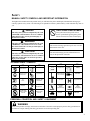
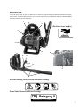
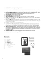
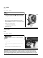
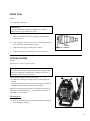
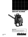
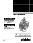
SHINDAIWA OWNER’S/OPERATOR’S MANUAL
EB508RT BLOWER
WARNING!
Minimize the risk of injury to yourself and others!
Read this manual and familiarize yourself with the contents. Always
wear eye and hearing protection when operating this unit.
X7507810000
11/12
Introduction
The Shindaiwa EB508RT Blower is designed and built to deliver superior performance and reliability without compromise to quality, comfort, safety, or durability. Shindaiwa high performance engines represent the leading edge of 2-cycle
engine technology, and deliver exceptionally high power at remarkably low displacement and weight. As a professional
owner/operator, you’ll soon discover why Shindaiwa is simply in a class by itself.
the operator's manual
Keep it in a safe place for future reference. Contains specifications and
information for safety, operation, maintenance, storage, and assembly
specific to this product.
SHINDAIWA OWNER’S/OPERATOR’S MANUAL
EB508RT BLOWER
WARNING!
Minimize the risk of injury to yourself and others!
Read this manual and familiarize yourself with the contents. Always
wear eye and hearing protection when operating this unit.
X7507810000
12/12
Table of Contents
Introduction................................................................. 2
- The Operator's Manual........................................2
Safety..........................................................................3
Manual Safety Symbols and Important Information..3
- International Symbols..........................................3
- Personal Condition and Safety Equipment.......... 3
-Equipment............................................................6
Emission Control........................................................ 6
Description.................................................................. 7
Contents .....................................................................8
Assembly.................................................................... 9
- Install Blower Pipes.............................................9
Operation...................................................................10
- Fuel....................................................................10
- Starting Cold Engine..........................................12
- Starting Warm Engine........................................13
- Stopping Engine.................................................13
- Operating Blower...............................................14
CopyRight© 2012 By Shindaiwa, Incorporated
All Rights Reserved.
2
Maintenance.............................................................. 15
- Skill Levels........................................................ 15
- Maintenance Intervals........................................15
- Air Filter............................................................ 16
- Fuel Filter...........................................................16
- Spark Plug..........................................................17
- Cooling System..................................................17
- Exhaust System..................................................18
- Carburetor Adjustment.......................................20
- High Altitude Operation.................................20
Troubleshooting........................................................21
Storage...................................................................... 22
Specifications............................................................23
Warranty Statement...................................................24
Servicing Information...............................................28
IMPORTANT
The information contained in these instructions
describes units available at the time of publication.
Shindaiwa Inc. reserves the right to make changes to
products without prior notice, and without obligation to
make alterations to units previously manufactured.
Safety
manual safety symbols and important information
Throughout this manual and on the product itself, you will find safety alerts and helpful, informational messages preceded by symbols or key words. The following is an explanation of those symbols and key words and what they mean to
you.
Circle and slash symbol
DANGER
This symbol means the specific action
shown is prohibited. Ignoring these prohibitions can result in serious or fatal injury.
The safety alert symbol accompanied by the word
“DANGER” calls attention to an act or condition
which WILL lead to serious personal injury or
death if not avoided.
WARNING
The safety alert symbol accompanied by the word
“WARNING” calls attention to an act or condition which CAN lead to serious personal injury or
death if not avoided.
CAUTION
The safety alert symbol accompanied by the word
“CAUTION” calls attention to an act or condition
which may lead to minor or moderate personal
injury if not avoided.
NOTE
This enclosed message provides tips for use, care and
maintenance of the unit.
IMPORTANT
The enclosed message provides information necessary for the protection of the unit.
international symbols
Symbol form/shape
Symbol
description/application
Read and understand
Operator's Manual.
Wear eyes, ears and
head protection
Hot
Surface
Safety/Alert
DO NOT allow
flames or sparks
near fuel.
Symbol form/shape
Symbol
description/application
Symbol form/shape
Symbol
description/application
Symbol form/shape
Symbol
description/application
Ignition
ON/OFF
Fuel and oil mixture
Emergency stop
Finger Severing
Carburetoradjustment
- Low speed mixture
Primer bulb
Carburetor adjustment
- Idle speed
Carburetor adjustment
- High speed mixture
Choke Control
"Cold Start"
Position
(Choke Closed)
Choke Control
"Run"
Position
(Choke Open)
Wear hand
protection. Use
two handed.
Wear slip resistant foot wear.
DO NOT smoke
near fuel.
Idle Speed
Fast Speed
personal condition and safety equipment
WARNING
Users of this product risk injury to themselves and others if the unit is used improperly and/or safety precautions are
not followed. Proper clothing and safety gear must be worn when operating unit.
3
Physical Condition
Your judgment and physical dexterity may not be good:
• if you are tired or sick,
• if you are taking medication,
• if you have taken alcohol or drugs.
Operate unit only if you are physically and mentally well.
Eye Protection
Wear eye protection that meets ANSI Z87.1 or CSA Z94.3
requirements whenever you operate the unit.
Hand Protection
Wear no-slip, heavy-duty work gloves to improve your
grip on the blower handle. Gloves also reduce the transmission of machine vibration to your hands.
Breathing Protection
Wear a facemask to protect against dust.
Hearing Protection
Proper Clothing
Wear snug fitting, durable clothing;
• Pants should have long legs, shirts with long sleeves.
• DO NOT WEAR SHORTS,
• DO NOT WEAR TIES, SCARVES, JEWELRY,
or clothing with loose or hanging items that could
become entangled in moving parts or surrounding
growth..
Wear sturdy work shoes with nonskid soles;
• DO NOT WEAR OPEN TOED SHOES,
• DO NOT OPERATE UNIT BAREFOOTED.
Wear no-slip, heavy duty work gloves.
Keep long hair away from engine and air intake. Retain
hair with cap or net.
Hot Humid Weather
Heavy protective clothing can increase operator fatigue
which may lead to heat stroke. Schedule heavy work for
early morning or late afternoon hours when temperatures
are cooler.
Shindaiwa recommends wearing hearing protection whenever unit is used.
WARNING
The ignition components of this machine generate an electromagnetic field during operation which may interfere
with some pacemakers. To reduce the risk of serious or fatal injury, persons with pacemakers should consult with
their physician and the pacemaker manufacturer before operating this machine. In the absence of such information, Shindaiwa does not recommend the use of Shindaiwa products by anyone who has a pacemaker.
Vibration and Cold
It is believed that a condition called Raynaud’s Phenomenon, which affects the fingers of certain individuals, may be
brought about by exposure to vibration and cold. Exposure to vibration and cold may cause tingling and burning sensations, followed by loss of color and numbness in the fingers. The following precautions are strongly recommended,
because the minimum exposure, which might trigger the ailment, is unknown.
• Keep your body warm, especially the head, neck, feet, ankles,
hands, and wrists.
• Maintain good blood circulation by performing vigorous arm
exercises during frequent work breaks, and also by not smoking.
• Limit the hours of operation. Try to fill each day with jobs where
operating the unit or other hand-held power equipment is not
required.
• If you experience discomfort, redness, and swelling of the fingers
followed by whitening and loss of feeling, consult your physician
before further exposing yourself to cold and vibration.
4
Repetitive Stress Injuries
It is believed that overusing the muscles and tendons of the fingers, hands, arms, and shoulders may cause soreness,
swelling, numbness, weakness, and extreme pain in those areas. Certain repetitive hand activities may put you at a high
risk for developing a Repetitive Stress Injury (RSI). An extreme RSI condition is Carpal Tunnel Syndrome (CTS), which
could occur when your wrist swells and squeezes a vital nerve that runs through the area.
Some believe that prolonged exposure to vibration may contribute to CTS. CTS can cause severe pain for months or
even years.
To reduce the risk of RSI/CTS, do the following:
• Avoid using your wrist in a bent, extended, or twisted position.
Instead try to maintain a straight wrist position. Also, when
grasping, use your whole hand, not just the thumb and index
finger.
• Take periodic breaks to minimize repetition and rest your hands.
• Reduce the speed and force with which you do the repetitive
movement.
• Do exercises to strengthen the hand and arm muscles.
• Immediately stop using all power equipment and consult a doctor if you feel tingling, numbness, or pain in the fingers, hands,
wrists, or arms. The sooner RSI/CTS is diagnosed, the more
likely permanent nerve and muscle damage can be prevented.
danger
Do not operate this product indoors or in inadequately ventilated
areas. Engine exhaust contains poisonous emissions and can cause
serious injury or death.
Read the Manuals
• Provide all users of this equipment with the Operator’s Manual
for instructions on Safe Operation.
Clear the Work Area
• Spectators and fellow workers must be warned, and children and
animals prevented from coming nearer than 15 m (50 ft.) while
the unit is in use.
• Take wind conditions into account: avoid open doors and windows.
• Do not point blower at people or animals.
Keep a Firm Grip
• Hold the front and rear handles with both hands, with thumbs
and fingers encircling the handles.
Keep a Solid Stance
• Maintain footing and balance at all times. Do not stand on slippery, uneven or unstable surfaces. Do not work in odd positions
or on ladders. Do not over reach.
Avoid Hot Surfaces
• Keep exhaust area clear of flammable debris. Avoid contact during and immediately after operation.
5
equipment check
WARNINg
Use only Shindaiwa approved attachments. Serious injury may result from the use of a non-approved attachment
combination. SHINDAIWA, INC. will not be responsible for the failure of cutting devices, attachments or accessories which have not been tested and approved by Shindaiwa. Read and comply with all safety instructions listed in
this manual and safety manual.
• Check unit for loose/missing nuts, bolts and screws. Tighten and/or replace as needed.
• Do not use blower if any part is missing or damaged.
• Have repairs done only by an authorized Shindaiwa Service dealer.
• Do not use any attachment, accessory or replacement part unless it is recommended in this Operator's Manual.
WARNING
Operation of this equipment may create sparks that can start fires. This unit is equipped with a spark arrestor to
prevent discharge of hot particles from the engine. Metal blade use also can create sparks if the blade strikes rocks,
metal, or other hard objects. Contact local fire authorities for laws or regulations regarding fire prevention requirements.
Emission Control (exhaust & evaporative)
EPA 2010 and Later and/or C.A.R.B. TIER III
The emission control system for the engine is EM (engine
modification) and, if the second to last character of the
Engine Family on the Emission Control Information label
(sample below) is “C”, “K”, or “T”, the emission control
system is EM and TWC (3-way catalyst). The fuel tank/fuel
line emission control system is EVAP (evaporative emissions). Evaporative emissions for California models are only
applicable to fuel tanks.
An Emission Control Label is located on the engine.
(This is an EXAMPLE ONLY, information on label varies
by engine FAMILY).
PRODUCT EMISSION DURABILITY (EMISSION COMPLIANCE PERIOD)
The 50 or 300 hour emission compliance period is the time span selected by the manufacturer certifying the engine
emissions output meets applicable emissions regulations, provided that approved maintenance procedures are followed as listed in the Maintenance Section of this manual.
6
Description
Locate the safety decals on your unit. Make sure the decals are legible and that you understand and follow the instructions on them. If a decal cannot be read, a new one can be ordered from your Shindaiwa dealer. See PARTS ORDERING instructions for specific information.
7
1
2
Hot Decal (near muffler)
6
5
4
3
10
8
11
12
13
9
15
14
General Warning Decal (located on blower housing)
Sound Label (located on blower housing)
dB(A)
70 Category II
Measured at 50 ft. (15m) per ANSI B175.2
7
2. SPARK PLUG - Provides spark to ignite fuel mixture.
3. SAFETY DECAL - Lists important safety precautions.
4. SPARK ARRESTOR - CATALYTIC MUFFLER / MUFFLER - The muffler or catalytic muffler controls exhaust noise
and emission. The spark arrestor screen prevents hot, glowing particles of carbon from leaving the muffler. Keep exhaust
area clear of flammable debris.
5. RECOIL STARTER HANDLE - Pull recoil handle slowly until starter engages, then quickly and firmly. When engine
starts, return handle slowly. DO NOT let handle snap back or damage to unit will occur.
1. SAFETY DECAL - Lists important safety precautions.
Move lever
up to- "Cold
Start"
( to) ignite
startingfuel
position
and for emergency stopping. Move lever down to Run
6. CHOKE
2. -SPARK
PLUG
Provides
spark
mixture.
position (
).
3. Spark arrestor muffler or spark arrestor muffler with catalyst - The muffler or
catalytic
mufflerpurge
controls
noise and
emission.
arrestor
screen
prevents
glowing
- Pumping
bulbexhaust
before starting
engine
draws The
freshspark
fuel from
the fuel
tank,
purginghot,
air from
the particles of
7. PURGE BULB
from leaving
thefuel
muffler.
Keep
area clear
flammable
carburetor. carbon
Pump purge
bulb until
is visible
andexhaust
flows freely
in theof
clear
fuel tankdebris.
return line. Pump purge bulb an
4. 4RECOIL
STARTER HANDLE - Pull recoil handle slowly until starter engages, then quickly and firmly. When
additional
or 5 times.
engine starts, return handle slowly. DO NOT let handle snap back or damage to unit will occur.
TANK
fuel -and
fuel filter.
8. FUEL
5.
AIR- Contains
CLEANER
Contains
replaceable air filter element.
6.
FUEL
TANK
CAP
Covers
seals fuel tank.
TANK
CAP
- Covers
and- seals
fueland
tank.
9. FUEL
7. SHOULDER HARNESS - Used to support unit on operator's back. The straps are adjustable.
10. BLOWER PIPES - Exclusive positive locking system.
8. CHOKE - Move lever UP to close choke (
) (starting position) and for emergency stopping. Move DOWN to
POSITION
- Pull back to increase engine speed. Friction washers maintain throttle lever setting.
11. THROTTLE
) (run position).
open
choke ( LEVER
9. PURGE BULB - Pumping purge bulb before starting engine draws fresh fuel from the fuel tank, purging air from
the carburetor. Pump purge bulb until fuel is visible and flows freely in the clear fuel tank return line. Pump purge
bulbHARNESS
an additional
4 orto5 support
times. unit on operator's back. The straps are adjustable.
- Used
13. SHOULDER
10.HANDLE - Used by operator to direct and control air flow.
- Used by operator THROTTLE
to direct and control
air flow./ STOP SWITCH BUTTON - Controls engine speed and turns
14. HANDLE
11. COMBINATION
POSITION
ignition on or off. Forward position - STOP. First detent position - IDLE. Move button back to increase speed,
15. THROTTLE TRIGGER - Spring loaded to return to idle when released. During acceleration, press trigger gradually for
forward
to decrease speed. Use Throttle Position Button to set and hold blower speed for continuous operation.
best operating
technique.
12. THROTTLE TRIGGER - Spring - loaded Throttle Trigger controls engine speed. Releasing Trigger returns enKNOB
- Allows
adjust handle
for optimum
comfort
andtrigger
control.
gine
to speed
set byoperator
ThrottletoPosition
Stop position
Switch Button.
Always
release
and allow engine to return to idle
16. LOCKING
before shutting off with Throttle Position Stop Switch Button. Use Throttle Trigger to vary blower speed settings
- Allows
for full range of movement.
17. FLEXIBLE
forPIPE
intermittent
operation.
13. LOCKING KNOB - Allows operator to adjust handle position for optimum comfort and control.
14. BLOWER PIPES - Exclusive positive locking system.
15. FLEXIBLE PIPE - Allows for full range of movement.
12. STOP SWITCH - Slide switch mounted on top of handle. Move forward to run, back to stop.
ConTenTs
Contents
___
___
___
___
___
___
___
___
___
___
1
1
1
1
1
1
1
1
8
-
Power
___
1 -Head
Power Head
Flex1Pipe
___
- Flex Pipe
Pipe1w/swivel
___
- Pipe w/swivel
Straight
Pipe
___
1 - Straight
Pipe
Straight
Pipe
___
1 - Straight
Pipe w/decal
Operator's
Manual Manual
___
1 - Operator's
Warranty
Registration
Card Card
___
1 - Warranty
Registration
Plastic
___
1 - Bag
Plastic Bag
2 - Clamps
___
2 - w/screws
Clamps w/screws
1 - Guide
___
1 Loop
- Guide Loop
SHINDAIWA OWNER’S/OPERATOR’S MANUAL
EB508RT BLOWER
WARNING!
Minimize the risk of injury to yourself and others!
Read this manual and familiarize yourself with the contents. Always
wear eye and hearing protection when operating this unit.
X7507810000
12/12
Assembly
G
WARNING
Never perform maintenance or assembly procedures with engine
running or serious personal injury may result.
install blower pipes
G
A
B
A
1. Place guide loop (G) across clamp, and turn until clip fully engages clamp band.
NOTE
Clamp with cable guide loop (G) fits elbow end of flexible pipe (B).
2. Assemble clamps (A) onto both ends of flexible pipe (B).
3. Assemble flexible pipe (B) to elbow (D) on blower. Position
guide loop (G) on inside (blower side) of flexible tube and tighten
clamp (A).
NOTE
A light lubricant may be used to ease assembly of flexible pipe to
blower elbow.
NOTE
Hang handle freely from blower to assure throttle cable is not
twisted before installing handle (E).
E
F
D
A
A
B
4. Position cable between the elbow (D) and frame and along the top
of the flexible pipe. Loosen knob (H) on handle (E). Align notch
in handle with tabs (F). Install onto swivel pipe (C) past long
ridges in pipe.
C
H
G
5. Assemble swivel pipe (C) into flexible pipe (B) and tighten clamp
(A).
6. Clip throttle cable into throttle cable guide loop (G).
E
7. Move handle (E) to desired position. Tighten knob (H) hand tight.
8. Assemble straight pipe (I) onto swivel pipe (C), until you feel
light resistance. Do not force connection. Hold swivel pipe and
turn straight pipe clockwise, engaging positive locking channels,
until connection is firm. Do not force connection.
H
9. Assemble straight pipe with decal (J) to straight pipe (I) as in step
8.
NOTE
Blower use will eventually loosen pipe connections. Exclusive
positive locking system allows pipes to be tightened. If loosening
occurs, remove two straight pipes and install according to instructions 8 & 9.
E
I
J
C
9
Operation
WARNING
Moving parts can amputate fingers or cause severe injuries. Keep hands, clothing and loose objects away from all
openings. Always stop engine, disconnect spark plug, and make sure all moving parts have come to a complete stop
before removing obstructions, clearing debris, or servicing unit. Blower housing may contain shredder blades and
other sharp edges that can cause serious injuries if touched, even if engine is off and blades are not moving. Wear
gloves to protect hands from sharp edges and hot surfaces.
WARNING
Operation of this equipment may create sparks that can start fires. This unit is equipped with a spark arrestor to
prevent discharge of hot particles from the engine. Metal blade use also can create sparks if the blade strikes rocks,
metal, or other hard objects. Contact local fire authorities for laws or regulations regarding fire prevention requirements.
NOTICE: Use of unmixed, improperly mixed, or fuel older than 90 days, (stale fuel), may cause hard starting, poor
performance, or severe engine damage and void the product warranty. Read and follow instructions in the Storage
section of this manual.
fuel
WARNING
Alternative fuels, such as E-15 (15% ethanol), E-85 (85% ethanol) or any fuels not meeting Shindaiwa requirements
are NOT approved for use in Shindaiwa 2-stroke gasoline engines. Use of alternative fuels may cause performance
problems, loss of power, overheating, fuel vapor lock, and unintended machine operation, including, but not limited
to, improper clutch engagement. Alternative fuels may also cause premature deterioration of fuel lines, gaskets,
carburetors and other engine components.
Fuel Requirements
Gasoline - Use 89 Octane [R+M/2] (mid grade or higher) gasoline known to be good quality. Gasoline may contain up to
10% Ethanol (grain alcohol) or 15% MTBE (methyl tertiary-butyl ether). Gasoline containing methanol (wood alcohol)
is NOT approved.
For increased engine protection, Shindaiwa recommends using Shindaiwa Red ArmorTM engine oil to protect the engine
from harmful carbon build up, maintain engine performance, and increase engine life. Shindaiwa Red ArmorTM engine
oil exceeds ISO-L-EGD and J.A.S.O. M345/FD performance requirements.
IMPORTANT
Shindaiwa OneTM 2-Stroke oil or Red ArmorTM engine oil may be mixed at 50:1 ratio for application in all Shindaiwa engines sold in the past, regardless of ratio specified in those manuals.
IMPORTANT
Stored fuel ages. Do not mix more fuel than you expect to use in thirty (30) days, ninety (90) days when a fuel
stabilizer is added. Use of unmixed, improperly mixed, or stale fuel, may cause hard starting, poor performance,
or severe engine damage and void the product warranty. Read and follow instructions in the Long Term Storage
section of this manual.
10
Handling Fuel
DANGER
Fuel is VERY flammable. Use extreme care when mixing, storing or handling or serious personal injury may result.
•Use an approved fuel container.
•DO NOT smoke near fuel.
•DO NOT allow flames or sparks near fuel.
•Fuel tanks/cans may be under pressure. Always loosen fuel caps slowly allowing pressure to equalize.
•NEVER refuel a unit when the engine is HOT or RUNNING!
•DO NOT fill fuel tanks indoors. ALWAYS fill fuel tanks outdoors over bare ground.
• DO NOT overfill fuel tank. Wipe up spills immediately.
•Securely tighten fuel tank cap and close fuel container after refueling.
•Inspect for fuel leakage. If fuel leakage is found, do not start or operate unit until leakage is repaired.
•Move at least 3m (10 ft.) from refueling location before starting the engine.
Mixing Instructions
1. Fill an approved fuel container with half of the required amount
of gasoline.
2. Add the proper amount of 2-stroke oil to gasoline.
3. Close container and shake to mix oil with gasoline.
4. Add remaining gasoline, close fuel container, and remix.
Fuel to Oil Mix - 50:1 Ratio
U.S.
METRIC
Gas
Oil
Gas
Oil
Gallons
FL. oz.
Liter
cc.
1
2.6
4
80
2
5.2
8
160
5
13
20
400
IMPORTANT
Spilled fuel is a leading cause of hydrocarbon emissions. Some
states may require the use of automatic fuel shut-off containers
to reduce fuel spillage.
After use
• DO NOT store a unit with fuel in its tank. Leaks can occur. Return
unused fuel to an approved fuel storage container.
Storage - Fuel storage laws vary by locality. Contact your local government for the laws affecting your area. As a precaution, store fuel in
an approved, airtight container. Store in a well-ventilated, unoccupied
building, away from sparks and flames.
IMPORTANT
Stored fuel ages. Do not mix more fuel than you expect to use in
thirty (30) days, ninety (90) days when a fuel stabilizer is added.
IMPORTANT
Stored two-stroke fuel may separate. ALWAYS shake fuel container thoroughly before each use.
11
starting cold engine
• Recoil starter: Use short pulls - only 1/2-2/3 of rope length for starting. Do not allow the rope to snap back in. Always hold the unit
firmly.
1. Throttle Position / Stop Switch Button
Slide Throttle Position / Stop Switch Button (A) back to idle position.
2. Choke
Move choke (C) up to Cold Start position (
).
3. Purge Bulb
Pump purge bulb (D) until fuel is visible and flows freely in the
clear fuel tank return line. Pump bulb an additional 4 or 5 times.
A
4. Recoil Starter
Pull recoil starter handle (E) until engine fires, or a maximum of
5 pulls.
5. Choke
After engine fires (or 5 pulls), move choke lever (C) to “Run” (
) position, then pull starter handle/rope until engine starts and
runs. Allow unit to warm up at idle for several minutes.
NOTE
If engine does not start with choke in “Run” position after 5 pulls,
move choke to “Cold Start” (
) position, and repeat steps 4 & 5.
6. Throttle Lever
Allow engine to warm up for several minutes before use.
7. Throttle Lever
After engine warm-up, move throttle lever gradually to increase
engine RPM to desired operating speed.
12
C
E
D
starting warm engine
The starting procedure is the same as Cold Start except DO NOT close
the choke.
A
1. Throttle Position / Stop Switch Button
Slide Throttle position / Stop switch Button(A) back to idle position.
2. Purge Bulb
Pump purge bulb (D) until fuel is visible and flows freely in the
clear fuel tank return line. Pump bulb an additional 4 or 5 times.
3. Recoil Starter
Pull recoil starter handle (E) and engine should start. Do not use
choke (C).
NOTE
If engine does not start after 5 pulls, use cold start procedures.
C
E
D
stopping engine
1. Throttle Position / Stop Switch Button
Release throttle trigger. Move Throttle Position / Stop Switch
Button (A) forward to idle position and allow engine to return to
idle before shutting off engine.
2. Throttle Position / Stop Switch Button
Move Throttle Position / Stop Switch Button (A) all the way
forward to STOP position.
A
WARNING
If engine does not stop when stop switch is moved to STOP position:
•Be certain engine is at idle, otherwise engine may continue to run.
•Close choke - COLD START position - to stall engine.
•Have your Shindaiwa dealer repair stop switch before using
blower again.
13
operating blower
WARNING
Engine exhaust IS HOT, and contains Carbon Monoxide (CO), a poison gas. Breathing CO can cause unconsciousness, serious injury, or death. Exhaust can cause serious burns. ALWAYS blow exhaust away from your face and body.
WARNING
Always wear safety glasses, hearing protection, a face filter mask and take all safety precautions or serious personal
injury may result.
Do not point the blower pipe in the direction of people or pets.
IMPORTANT
Use reduced speed only when performing light-duty tasks or to comply with local noise regulations. Continuous
low speed operation may allow fuel/oil residue to build-up on the piston and cause rapid build-up of carbon on
the spark arrestor screen, resulting in overheating and engine damage. To reduce harmful build-up, run engine at
wide open throttle for at least 5 minutes every hour, and inspect/clean the spark arrestor screen every 40 hours of
operation.
Read the Safety Section carefully.
IMPORTANT
To avoid engine damage due to over-revving, do not block
blower pipe opening.
1. Use only during appropriate hours.
2. Allow the engine to warm up at a fast idle for a few minutes.
3. Control engine speed with throttle trigger (B), or for continuous
use, set engine speed with Combination Throttle Position / Stop
Switch Button (A).
A
4. Use lower speed to blow dry leaves from walks, patios and
drives.
5. Additional speed may be necessary to clean grass and leaves
from a lawn or flower bed.
6. Higher speed may be necessary to move gravel, dirt, snow,
bottles or cans from a driveway, street, parking lot or stadium.
7. Always stop unit using stop engine procedure.
NOTE
Never use a higher speed setting than necessary to perform a task.
Remember, the higher the engine speed, the louder the blower
noise. Minimize dust by using blower at lower speeds and by
dampening material with water/mist when necessary. Keep debris
on your property.
Be Smart - be a good neighbor.
14
B
Maintenance
WARNING
Moving parts can amputate fingers or cause severe injuries. Keep hands, clothing and loose objects away from all
openings. Always stop engine, disconnect spark plug, and make sure all moving parts have come to a complete stop
before removing obstructions, clearing debris, or servicing unit. Wear gloves to protect hands from sharp edges and
hot surfaces.
IMPORTANT
MAINTENANCE, REPLACEMENT OR REPAIR OF EMISSION CONTROL DEVICES AND SYSTEMS
MAY BE PERFORMED BY ANY REPAIR ESTABLISHMENT OR INDIVIDUAL, HOWEVER, WARRANTY
REPAIRS MUST BE PERFORMED BY A DEALER OR SERVICE CENTER AUTHORIZED BY SHINDAIWA
CORPORATION THE USE OF PARTS THAT ARE NOT EQUIVALENT IN PERFORMANCE AND DURABILITY TO AUTHORIZED PARTS MAY IMPAIR THE EFFECTIVENESS OF THE EMISSION CONTROL SYSTEM AND MAY HAVE A BEARING ON THE OUTCOME OF A WARRANTY CLAIM.
skill levels
Level 1 =
Level 2 =
Easy to do. Common tools may be required.
Moderate difficulty. Some specialized tools may be required.
maintenance intervals
COMPONENT / SYSTEM
MAINTENANCE
PROCEDURE
REQ'D
SKILL
LEVEL
DAILY OR
BEFORE USE
EVERY
REFUEL
3 MONTHS
YEARLY
Air Filter
Inspect/Clean
1
I/C*
Choke Shutter
Inspect/Clean
1
I/C
Fuel Filter
Inspect/Replace
1
I *
I/R*
Fuel Cap Gasket
Inspect/Replace
1
I *
R*
Fuel System
Inspect/Replace
1
Spark Plug
Inspect/Clean/Replace
1
Cooling System
Inspect/Clean
2
Muffler Spark Arrestor
Inspect/Clean/Replace
2
I/C/R*
Cylinder Exhaust Port
Inspect/Clean/Decarbon
2
I/C
Recoil Starter Rope
Inspect/Clean
1
I/C*
Screws/Nuts/Bolts
Inspect/Tighten/Replace
1
I *
I (1) *
R*
I (1) *
I/C/R*
I/C
MAINTENANCE PROCEDURE LETTER CODES: I = INSPECT, R = REPLACE, C = CLEAN
IMPORTANT NOTE - Time intervals shown are maximum. Actual use and your experience will determine the
frequency of required maintenance.
MAINTENANCE PROCEDURE NOTES:
(1) Low evaporative fuel tanks DO NOT require regular maintenance to maintain emission integrity.
* All recommendations to replace are based on the finding of damage or wear during inspection.
15
air filter
Level 1.
Parts required: Air Filter
NOTE
Clean daily.
1. Close choke (Cold Start Position [
]). This prevents dirt from
entering the carburetor throat when the air filter is removed. Brush
accumulated dirt from air cleaner area.
2. Remove air filter cover. Brush dirt from inside cover.
3. Remove air filter and lightly brush debris from filter. Replace
filter if it is damaged, fuel soaked, very dirty, or the rubber sealing
edges are deformed.
4. If filter can be reused, be certain it:
• Fits tightly in the air filter cavity.
• Is installed with the original side out.
5. Install air filter cover.
fuel filter
Level 1.
Parts required: Fuel Filter
DANGER
Fuel is VERY flammable. Use extreme care when mixing, storing
or handling.
1 . Use a clean rag to remove loose dirt from around fuel cap and empty fuel tank.
2. Use the “fuel line hook” to pull the fuel line and filter from the tank.
3. Remove the filter from the line and install the new filter.
NOTE
Federal EPA regulations require all model year 2012 and later gasoline powered engines produced for sale in the
United States to be equipped with a special low permeation fuel supply hose between the carburetor and fuel tank.
When servicing model year 2012 and later equipment, only fuel supply hoses certified by EPA can be used to replace
the original equipment supply hose. Fines up to $37,500 may be enforced for using an un-certified replacement part.
16
spark plug
Level 2.
Parts Required: Spark Plug IMPORTANT
Use only NGK BPM-8Y spark plug (BPMR-8Y in Canada)
otherwise severe engine damage may occur.
1. Remove spark plug and check for fouling, worn and rounded center electrode.
2. Clean the plug or replace with a new one. DO NOT sand blast to clean. Remaining sand will damage engine.
3. Adjust spark plug gap by bending outer electrode.
0.65 mm
(0.026 in.)
4. Tighten spark plug to 150-170 kgf • cm (130-150 in • lbf).
cooling system
Level 2.
Parts Required: None, if you are careful.
IMPORTANT
To maintain proper engine operating temperatures, cooling air must
pass freely through the cylinder fin area. This flow of air carries
combustion heat away from the engine.
Overheating and engine seizure can occur when:
• Air intakes are blocked, preventing cooling air from reaching the cylinder.
• Dust and grass build up on the outside of the cylinder. This build up insulates the engine and prevents the heat from leaving.
Removal of cooling passage blockages or cleaning of cooling fins is
considered “Normal Maintenance”. Any failure attributed to lack of
maintenance is not warranted.
Cleaning Grill
1. Remove accumulated debris from intake grill between backpack
frame and blower housing.
17
Cleaning Cylinder Fins
1. Disconnect spark plug lead from spark plug.
2. Remove engine cover (five screws), pull cover away from engine.
A
3. Clean cylinder fins (A) to allow cooling air to pass freely.
4. Replace cover and tighten screws.
5. Connect spark plug lead.
exhaust system
Spark Arrestor Screen
Level 2.
Parts Required: Spark arrestor screen, Gasket IMPORTANT
Carbon deposits in muffler will cause a drop in engine output and
overheating. Spark arrestor screen must be checked periodically.
1. Remove spark plug and engine cover (five screws).
2. Remove spark arrestor cover (A), gasket (B) and spark arrestor
screen (C) from muffler. Replace screen if plugged with carbon
deposits.
3. Install spark arrestor screen, gaskets, and cover.
4. Install spark plug and engine cover.
18
B
C
A
Exhaust Port Cleaning
Level 2
Parts Required: As needed: Muffler gasket
1. Remove spark plug lead from spark plug, and remove engine
cover.
2. Place piston at top dead center. Remove muffler (A) and muffler
gasket (B ).
A
3. Use a wood or plastic scraping tool to clean deposits from cylinder exhaust port.
IMPORTANT
Never use a metal tool to scrape carbon from the exhaust port.
Do not scratch the cylinder or piston when cleaning the exhaust
port. Do not allow carbon particles to enter the cylinder.
B
4. Inspect muffler gasket, and replace if damaged.
5. Install muffler gasket and muffler.
6. Tighten muffler mounting bolts (or nuts) to 80-95 in•lbf (90-110 kgf•cm).
7. Install engine cover and attach spark plug lead.
8. Start engine, and warm to operating temperature.
9. Stop engine, and re-tighten mounting bolts (or nuts) to specifications.
19
carburetor adjustment
Engine Break-In
New engines must be operated a minimum duration of two tanks of fuel
break-in before carburetor adjustments can be made. During the breakin period your engine performance will increase and exhaust emissions
will stabilize. Idle speed can be adjusted as required.
High Altitude Operation
This engine has been factory adjusted to maintain satisfactory starting,
emission, and durability performance up to 1,100 feet above sea level
(ASL) (96.0 kPa). To maintain proper engine operation and emission
compliance above 1,100 feet ASL the carburetor may need to be adjusted by an authorized ECHO service dealer.
Important
If the engine is adjusted for operation above 1,100 feet ASL, the
carburetor must be re-adjusted when operating the engine below
1,100 feet ASL, otherwise severe engine damage may result.
Level 2.
Parts required: None.
NOTE
Every unit is run at the factory and the carburetor is set in compliance with emission regulations. Carburetor adjustments, other than
idle speed, must be performed by an authorized ECHO dealer.
Idle Adjustment
Before adjustment make sure that:
• Air filter is clean and properly installed.
• Spark arrestor screen and muffler are free of carbon.
• Blower pipes are installed.
1. Start engine, run at idle for one minute.
2. Complete warm up by running at full throttle for 5 minutes, operating choke twice to clear air from carburetor chambers.
3. Check idle speed and reset if necessary. If a tachometer is available, idle speed screw (A) should be set to the specifications
found on "Specifications" Page of this manual. Turn idle screw
(A) clockwise to increase idle speed; counter clockwise to decrease idle speed.
20
English
TroubleshooTInG
TROUBLESHOOTING CHART
Problem
Engine cranks starts hard/
doesn't
start
C h eck
Status
Fuel at carburetor
No fuel at carburetor
Fuel at cylinder
C au se
Remedy
Fuel strainer clogged
Fuel line clogged
Carburetor
Clean or replace
Clean or replace
See your Shindaiwa dealer
No fuel at cylinder
Carburetor
See your Shindaiwa dealer
Muffler wet with fuel
Fuel Mixture too rich
Open choke
Clean/replace air filter
Adjust carburetor
See your Shindaiwa dealer
Spark at end
of plug wire
No spark
Stop switch off
Electrical problem
Interlock switch
Turn switch to ON
See your Shindaiwa dealer
See your Shindaiwa dealer
Spark at plug
No spark
Spark gap incorrect
Covered with carbon
Fouled with fuel
Plug defective
Adjust to .65mm (0.026 in.)
Clean or replace
Clean or replace
Replace plug
Air filter
Air filter dirty
Normal wear
Clean or replace
Fuel filter
Fuel filter dirty
C ontaminants/residues in
fuel
Replace
Fuel vent
Fuel vent plugged
Spark Plug
Plug dirty/worn
Carburetor
Improper adjustment
Cooling System
Cooling system
dirty/plugged
Spark Arrestor Screen
Spark arrestor screen
plugged
Engine does
not crank
N/A
N/A
Engine runs,
blower doesn't
work or is
weak/uneven
Blower pipe
Pipe clogged
Engine runs,
but dies or
does not
accelerate
properly
Pipe loose
Pipe damaged
C ontaminants/residues in fuel Clean or replace
Normal wear
Clean and adjust or replace
Vibration
Adjust
Extended operation in
dirty/dusty locations
Clean
Normal wear
Replace
Internal engine problem
See your Shindaiwa dealer
Build-up of debris
Unclog
Vibration
Tighten
Wear/Misuse
Replace
DANGER
Fuel vapors are extremely flammable and may cause fire and/or explosion. Never test for ignition spark by
grounding spark plug near cylinder plug hole, otherwise serious personal injury may result.
21
Storage
warning
During operation the muffler or catalytic muffler and surrounding cover become hot. Always keep exhaust area clear
of flammable debris during transportation or when storing, otherwise serious property damage or personal injury may
result.
Long Term Storage (Over 30 Days)
Do not store your unit for a prolonged period of time (30 days or longer) without performing protective storage maintenance which includes the following:
1. Store unit in a dry, dust free place, out of the reach of children.
DANGER
Do not store in enclosure where fuel fumes may accumulate or reach an open flame or spark.
3. Remove accumulation of grease, oil, dirt and debris
from exterior of unit.
7. A. Allow engine to cool then remove the spark plug and pour 7 cc (1/4 oz.) of fresh, clean, two-stroke engine oil into the cylinder through the spark plug hole.
4. Perform all periodic lubrication and services that are
required.
B. Pull the recoil starter handle 2-3 times to
distribute the oil inside the engine.
5. Tighten all screws and nuts.
C. Observe the piston location through the spark plug hole. Pull the recoil handle slowly until the piston reaches the top of its travel and leave it there.
2. Place the stop switch in the "STOP" position.
6. Drain fuel tank completely. Press purge bulb 6 - 7
times to remove remaining fuel from carburetor then
drain the tank again. Close choke, start and run the
engine until it stops due to lack of fuel.
8. Install the spark plug (do not connect ignition
cable).
9. Remove blower pipe assembly from unit.
22
Specifications
MODEL���������������������������������������������������� EB508RT
Length ������������������������������������������������������ 328mm (12.9 in.)
Width ������������������������������������������������������ 470 mm (18.5 in.)
Height������������������������������������������������������� 490 mm (19.3 in.)
Weight (dry) ���������������������������������������������� 9.3 kg (22.0 lb.)
Engine Type������������������������������������������������ Air cooled, two-stroke, single cylinder gasoline engine
Displacement����������������������������������������������� 50.8cc (3.10 cu. in.)
Bore���������������������������������������������������������� 43.0 mm (1.69 in.)
Stroke�������������������������������������������������������� 35.0 mm (1.38 in.)
Carburetor�������������������������������������������������� Diaphragm model w/purge bulb
Ignition System�������������������������������������������� Flywheel Magneto, capacitor discharge ignition type
Spark Plug�������������������������������������������������� NGK BPM8Y Gap 0.65 mm (0.026 in.)
Exhaust System�������������������������������������������� Spark arrestor muffler or spark arrestor muffler with catalyst
Fuel���������������������������������������������������������� Mixed (Gasoline and Two-stroke Oil)
Fuel/Oil Ratio���������������������������������������������� 50 : 1 two-stroke, air-cooled engine oil.
Gasoline����������������������������������������������������� Use 89 Octane unleaded. Do not use fuel containing methyl
alcohol, more than 10% ethyl alcohol or 15% MTBE. Do not use
alternative fuels such as E-15 or E-85.
Oil������������������������������������������������������������ Shindaiwa OneTM oil or Red Armor oil ISO-L-EGD (ISO/CD
13738) JASO M345-FD. 50 : 1 two stroke, air cooled engine oil.
Fuel Tank Capacity���������������������������������������� 1.72 lit. (58.2 US fl. oz.)
Recoil Starter System������������������������������������� Automatic Recoil Starter Centrifugal Type
Idle Speed �������������������������������������������������� 2,650 (RPM)
Wide Open Throttle Speed ������������������������������� 6,650 (RPM)
Average Air Speed w/pipes������������������������������� 72.87 m/sec (163 mph)
Maximum Air Speed w/pipes���������������������������� 87.17 m/sec (195 mph)
Maximum Air Volume w/pipes�������������������������� 13.17 m3/min. (465 cu. ft./min.)
Sound level at 50 ft. dB(A) scale per ANSI B175.2�� 70 dB(A)
23
Warranty Statements
SHINDAIWA LIMITED WARRANTY STATEMENT FOR
PRODUCT SOLD IN USA AND CANADA BEGINNING 01/01/2010
ECHO, INC’S RESPONSIBILITY
ECHO Incorporated’s (ECHO, INC.) Limited Warranty, provides to the original purchaser that this Shindaiwa product is free from
defects in material and workmanship. Under normal use and maintenance from date of purchase, ECHO, INC. agrees to repair
or replace at it’s discretion, any defective product free of charge at any authorized Shindaiwa servicing dealer within listed below
application time periods, limitations and exclusions. THIS LIMITED WARRANTY IS ONLY APPLICABLE TO SHINDAIWA PRODUCTS SOLD BY AUTHORIZED SHINDAIWA DEALERS. IT IS EXTENDED TO THE ORIGINAL PURCHASER ONLY, AND IS
NOT TRANSFERABLE TO SUBSEQUENT OWNERS EXCEPT FOR EMISSION RELATED PARTS. Repair parts and accessories replaced under this warranty are warranted only for the balance of the original unit or accessory warranty period. Any damage caused by improper installation or improper maintenance is not covered by this warranty. All parts or products replaced under
warranty become the property of ECHO, INC. This warranty is separate from the Emission control warranty statement supplied with
your new product. Please consult the Emission Control Warranty Statement for details regarding emission related parts. For a list
of Authorized Shindaiwa Dealers refer to WWW.SHINDAIWA.COM or call 1-877-986-7783.
OWNER’S RESPONSIBILITY
To ensure trouble free warranty coverage it is important that you register your Shindaiwa equipment on-line at WWW.SHINDAIWA.
COM or by filling out the warranty registration card supplied with your unit. Registering your product confirms your warranty coverage and provides a direct link if we find it necessary to contact you.
The owner shall demonstrate reasonable care and use, and follow preventative maintenance, storage, fuel and oil usage as prescribed in the operator’s manual. Should a product difficulty occur, you must, at your expense, deliver or ship your Shindaiwa unit
to an authorized Shindaiwa servicing dealer for warranty repairs (within the applicable warranty period), and arrange for pick-up
or return of your unit after the repairs have been made. For your nearest authorized Shindaiwa servicing dealer, call Shindaiwa’s
Dealer Referral Center, at 1-877-986-7783 or you can locate a Shindaiwa servicing dealer at WWW.SHINDAIWA.COM. Should you
require assistance or have questions concerning Shindaiwa’s Warranty Statement, you can contact our Consumer Product Support
Department at 1-800-673-1558 or contact us through the web at WWW.SHINDAIWA.COM.
PRODUCT WARRANTY PERIOD
RESIDENTIAL APPLICATION
•
2 YEAR WARRANTY - Units for residential, or non-income producing use will be covered by this limited warranty for
two (2) years from date of purchase.
EXCEPTIONS:
• For engine powered products, the electronic ignition module, flexible drive cable, and solid drive shaft are warranted for
the life* of the product on parts only.
• Cutting attachments such as, but not limited to, bars, chains, sprockets, tines, blades, PowerBroomTM, belts, and nylon
trimmer heads for residential or non-income producing use will be covered for failures due to defects in material or
workmanship for a period of 60 days from original product purchase date. Any misuse from contact with concrete,
rocks, or other structures is not covered by this warranty.
• Multipurpose Tool Attachments carry the same warranty duration as the units they are designed to fit.
COMMERCIAL APPLICATION
• 90 DAY WARRANTY - All Chain Saws and Cut-Off Saws for commercial, institutional, agricultural, industrial, or income producing use will be covered by this limited warranty for 90 Days from the date of purchase.
• 2 YEAR WARRANTY - Units for commercial, institutional, agricultural, industrial, or income producing use will be covered by
this limited warranty for two (2) years from the date of purchase.
EXCEPTIONS:
• For engine powered products, the electronic ignition module, flexible drive cables, and solid drive shafts are warranted
for the life* of the product on parts only.
• Cutting attachments such as, but not limited to, bars, chains, sprockets, tines, blades, PowerBroomTM, belts, and nylon
trimmer heads for commercial, institutional, agricultural, industrial, rental, or income producing will be covered for failures due to defects in material or workmanship for a period of 30 days from original product purchase date. Any misuse
from contact with concrete, rocks, or other structures is not covered by this warranty.
• Multipurpose Tool Attachments carry the same warranty duration as the units they are designed to fit.
RENTAL APPLICATION - 90 DAYS WARRANTY
• Units for rental use will be covered against defects in material and workmanship for a period of 90 days from the date of purchase.
*
24
ECHO INC’s liability under the “Lifetime” coverage is limited to furnishing parts specified under the PRODUCT Warranty
PERIOD section of this warranty statement for “Life” free of charge for a period of ten (10) years after the date of the complete
unit’s final production.
PURCHASED REPAIR PARTS AND ACCESSORIES
• 90-day all applications
ATTENTION ENGINE POWERED PRODUCT OWNERS
This Shindaiwa engine powered product is a quality-engineered unit which has been manufactured to exact tolerances to provide
superior performance. To help ensure the performance of the unit, it is required to use engine oil which meets the ISO-L-EGD
Standard per ISO/CD 13738 and JASO M345/FD Standards. Shindaiwa Red ArmorTM and Shindaiwa OneTM are a premium engine
oil specifically formulated to meet ISO-L-EGD (ISO/CD 13738) and JASO M345/FD Standards. The use of engine oils designed
for other applications, such as for outboard motors or lawnmowers can result in severe engine damage, and will void your engine
limited warranty.
THIS WARRANTY DOES NOT COVER DAMAGE CAUSED BY:
• Lack of lubrication or engine failure, due to the use of engine oils that do not meet the ISO-L-EGD (ISO/CD 13738) and JASO
M345/FD Standards. Shindaiwa Red ArmorTM and Shindaiwa OneTM Engine Oil meets the ISO-L-EGD and JASO M345/FD
Standard. Emission related parts are covered for 2 years regardless of engine oil used, per the statement listed in the EPA or
California Emission Control Warranty Explanation.
• Damage caused by use of gasohol, containing methanol (wood alcohol), or gasoline containing less than 89 octane. Only use
gasoline which contains 89 octane or higher. Gasohol which contains a maximum 10% ethanol (grain alcohol) or 15% MTBE
(methyl/tertiary/butyl/ether) is also approved. The prescribed mixing ratio of gasoline to oil is listed on the Shindaiwa oil label and
covered in your operator’s manual.
• Engine damage caused by use of ether or any starting fluids.
• Damage caused by tampering with engine speed governor or emission components, or running engines above specified and
recommended engine speeds as listed in your operator’s manual.
• Operation of the unit with improperly maintained/removed cutting shield or removed/damaged air filter.
• Damage caused by dirt, pressure or steam cleaning the unit, salt water, corrosion, rust, varnish, abrasives, and moisture.
• Defects, malfunctions or failures resulting from abuse, misuse, neglect, modifications, alterations, normal wear, improper servicing, or use of unauthorized attachments.
• Incorrect storage procedures, stale fuel, including failure to provide or perform required maintenance services as prescribed in
the operator’s manual. Preventative maintenance as outlined in the operator’s manual is the customer’s responsibility.
• Failures due to improper set-up, pre-delivery service or repair service by anyone other than authorized Shindaiwa servicing
dealer during the warranty period.
• Certain parts and other items are not warranted, including but not limited to: lubricants, starter cords, and engine tune-ups.
• Use of spark plugs other than those meeting performance and durability requirements of the OEM spark plug listed in the Operator’s Manuals.
• Overheating or carbon scoring failures due to restricted, clogged exhaust port or combustion chamber, including damage to
spark arrester screen.
• Adjustments after the first (30) thirty days and beyond, such as carburetor adjustment and throttle cable adjustment.
• Damage to gears or gear cases caused by contaminated grease or oil, use of incorrect type or viscosity of lubricants, and/or
failure to comply with recommended grease or oil change intervals.
• Damage caused by pump or sprayer running dry, pumping or spraying caustic or flammable materials, or lack of or broken
strainers.
• Additional damage to parts or components due to continued use after operational problem or failure occurs. Should operational
problem or failure occur, the product should not be used, but delivered as is to an authorized Shindaiwa servicing dealer.
It is a dealer’s and/or customer’s responsibility to complete and return the warranty registration card supplied with your Shindaiwa
product or by visiting WWW.SHINDAIWA.COM. Your receipt of purchase including date, model and serial number must be maintained and presented to an authorized Shindaiwa servicing dealer for warranty service. Proof of purchase rests solely with the customer. Some states do not allow limitations on how long an implied warranty lasts, so the above limitations may not apply to you.
Some states do not allow the exclusion or limitation of incidental or consequential damages, so you may also have other specific
legal rights which vary from state to state. This limited warranty is given by ECHO Incorporated, 400 Oakwood Rd., Lake Zurich, IL
60047.
DISCLAIMER OF IMPLIED WARRANTIES
This limited warranty is in lieu of all other expressed or implied warranties, including any warranty of FITNESS FOR A PARTICULAR PURPOSE OR USE and any implied warranty of MERCHANTABILITY otherwise applicable to this product. ECHO, INC. and
its affiliated companies shall not be liable for any special incidental or consequential damage, including lost profits. There are no
warranties extended other than as provided herein. This limited warranty may be modified only by ECHO, INC.
99922201031
06/2010
25
ECHO INCORPORATED EMISSION CONTROL WARRANTY STATEMENT
FOR ECHO AND SHINDAIWA BRANDS
The Environmental Protection Agency (EPA) and the California Air Resources Board (C.A.R.B.) and ECHO Incorporated (ECHO Inc.) are pleased
to explain the emission control system warranty on your 2010 and later equipment/small off-road engine (SORE). New equipment/SORE must be
designed, built and equipped to meet stringent EPA and C.A.R.B. anti-smog standards. ECHO Inc. must warrant the emission control system on
your equipment/SORE for the periods of time listed below, provided there has been no abuse, neglect or improper maintenance of your equipment/
SORE. Your emission control system may include parts such as: carburetor, fuel-injection system, ignition system, catalytic converter/muffler, fuel
tank, fuel feed lines, fuel cap assembly, spark plug, air filters, and other associated components. Where a warrantable condition exists, ECHO
Inc will repair your equipment/SORE at no cost to you including diagnosis, parts and labor. The Emission Control System warranty is extended
to the original owner including all subsequent owners.
MANUFACTURER'S WARRANTY COVERAGE:
The emission control system is warranted for 2 years or the length of the ECHO Inc. warranty, whichever is longer. If any emission-related part
on your equipment is defective, the part will be repaired or replaced by ECHO Inc. or its Authorized Service Representative.
OWNER'S WARRANTY RESPONSIBILITIES:
As the equipment/SORE owner, you are responsible for the performance of the required maintenance listed in your Operator's Manual. ECHO
Inc. recommends that you retain all receipts covering maintenance on your equipment/SORE however, ECHO Inc. cannot deny warranty solely
for the lack of receipts or for your failure to ensure the performance of all scheduled maintenance. As the equipment/SORE owner, you should be
aware that ECHO Inc. may deny you warranty coverage if your equipment/SORE or a part has failed due to abuse, neglect, improper maintenance
or unapproved modifications.
You are responsible for presenting your equipment/SORE to an ECHO Inc. authorized service representative as soon as a problem exists. The
warranty repairs should be completed in a reasonable amount of time, not to exceed 30 days. If a warrantable condition exists and there is no
Authorized Dealer within 100 miles, ECHO Inc. will pay to ship the unit to the nearest authorized dealer. If you have questions regarding your
warranty coverage, you should contact ECHO Inc. at 1-800-673-1558, web site WWW.ECHO-USA.COM or contact Shindaiwa at 1-877-9867783, web site WWW.SHINDAIWA.COM.
WHAT DOES THIS WARRANTY COVER?
ECHO Inc. warrants that your equipment/SORE was designed, built and equipped to conform with applicable EPA and C.A.R.B. emissions
standards and that your equipment/SORE is free from defects in material and workmanship that would cause it to fail to conform with applicable
requirements for 2 years or the length of the ECHO Inc. warranty, whichever is longer. The warranty period begins on the date the product is
purchased by an end user.
HOW WILL A COVERED PART BE CORRECTED?
If there is a defect in a part covered by this warranty, any ECHO Inc. Authorized Service Dealer will correct the defect. You will not have to pay
anything to have the part adjusted, repaired or replaced. This includes any labor and diagnosis for warranted repairs performed by the dealer. In
addition, engine parts not expressly covered under this warranty but whose failure is a result of a failure of a covered part will be warranted.
WHAT PARTS ARE COVERED?
Any applicable emission related part not scheduled for "required maintenance" will be repaired or replaced within the warranty period. The repaired
or replaced part will be warranted for the remaining ECHO Inc. warranty period.
Any warranted part that is scheduled only for regular inspection in the written instructions supplied is warranted for the warranty period stated
above. Any such part repaired or replaced under warranty will be warranted for the remaining ECHO Inc. warranty period.
Any emission related part scheduled for replacement during "required maintenance" is warranted for the period of time prior to the first scheduled
replacement point for that part. Any such part repaired or replaced under warranty shall be warranted for the remainder of the period prior to the
first scheduled replacement point for that part.
Any manufacturer-approved replacement part may be used in the performance of any warranty maintenance or repairs on emission related parts,
and must be provided without charge if the part is still under warranty.
Any replacement part that is equivalent in performance and durability may be used in non-warranty maintenance or repairs, and shall not reduce
the warranty obligations of the manufacturer.
Throughout the equipment/SORE warranty period, ECHO Inc. will maintain a supply of warranted parts sufficient to meet the expected demand
for such parts.
SPECIFIC EMISSION RELATED WARRANTED PARTS:
• Electronic Ignition System
• Catalytic Converter / Muffler Assembly
• Choke
• Fuel Tank
• Air Filter
• Spark Plug
• Carburetor (complete assembly or replaceable components)
• Fuel-Injection Assembly (or replaceable components)
• Fuel Cap Assembly
• Fuel Feed Line (and associated clamps/connectors as applicable)
WHAT IS NOT COVERED?
Any failure caused by abuse, neglect, improper maintenance, unapproved modifications, use of unapproved add-on parts/modified parts or
unapproved accessories.
This Emission Control Warranty is valid only for the U.S.A., it's Territories, and Canada.
26
99922201033
01/2010
notes
27
Servicing Information
Parts/Serial Number
Genuine Shindaiwa Parts and Assemblies for your Shindaiwa products are available only from an Authorized Shindaiwa Dealer. When you do need to buy parts always have the Model Number, Type and Serial Number of the unit with
you. You can find these numbers on the engine. For future reference, write them in the space provided below.
Model No. ___________________SN. ___________________
Service
Service of this product during the warranty period must be performed by an Authorized Shindaiwa Service Dealer.
For the name and address of the Authorized Shindaiwa Service Dealer nearest you, ask your retailer or call: 1-877986-7783. Dealer information is also available on WWW.SHINDAIWA.COM. When presenting your unit for Warranty
service/repairs, proof of purchase is required.
Consumer Product Support
If you require assistance or have questions concerning the application, operation or maintenance of this product you
may call the Shindaiwa Consumer Product Support Department at 1-877-986-7783 from 8:30 am to 4:30 pm (Central
Standard Time) Monday through Friday. Before calling, please know the model and serial number of your unit.
Warranty Registration
To ensure trouble free warranty coverage it is important that you register your Shindaiwa equipment by filling out the
warranty registration card supplied with your unit. Registering your product confirms your warranty coverage and provides a direct link if we find it necessary to contact you.
Additional or Replacement Manuals
Replacement Operator and Parts Catalogs are available from your Shindaiwa dealer or at WWW.SHINDAIWA.
COM or by contacting the Consumer Product Support Department (1-877-986-7783). Always check WWW.SHINDAIWA.COM for updated information.
ECHO Incorporated.
400 Oakwood Road
Lake Zurich, IL 60047-1564 U.S.A.
Telephone: 1-877-986-7783
Fax: 1-847-540-8416
www.shindaiwa.com
Copyright© 2012 By Echo, Incorporated
All Rights Reserved.
28
Yamabiko Corporation
7-2 Suehirocho 1-Chome, Ohme,
Tokyo, 198-8760, Japan
Phone: 81-428-32-6118
Fax: 81-428-32-6145
P38811001001/P38811999999
P38712001001/P38712999999