1
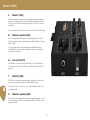
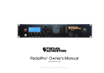
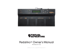
Acoustic box live1.0 rel A
Owner’s Manual
TM
Introduction
1.1
MESSAGE TO THE USERS
1.2
SUMMARY OF FEATURES
Thank you from all of us at Vintage Revolution for purchasing the Acoustic
Box preamp. We hope it will prove to be the best investment of your musical
career.
•
Impressive sound quality
•
Independent parametric equalizer per channel
Our objective in designing the Acoustic Box was simple: to eliminate compromise. We believe that this device will exceed even your wildest expectations for live stage or studio recording
•
Independent volume control for PA out and Amp out
•
48V phantom power
•
Master mute
•
Compact size and light
•
Manufactured in Italy
•
Neutrik audio connectors
•
Integrated toroidal power supply US-EU selectable
Enjoy your purchase.
From the team at VR
2
IMPORTANT SAFETY INSTRUCTIONS
To reduce the risk of fire or electric shock, unplug the apparatus when there
is high probability of lightning.
bent, stretched or pinched by items placed upon or against them, paying particular attention to cords, plugs, convenience receptacles and the point where they
exit from the apparatus.
CAUTION: To reduce the risk of electric shock, do not remove cover or back. No user
serviceable parts inside. Refer servicing to qualified service personnel.
7.
WARNING: To reduce the risk of fire or electric shock, do not expose this apparatus to
rain or moisture.
The lightning flash symbol within an equilateral triangle is intended to alert the
user to the presence of uninsulated ‘dangerous voltage’ within the product’s
enclosure that may be of sufficient magnitude to constitute a risk of electric
shock to persons.
8.
The exclamation point within an equilateral triangle is intended to alert the
user to the presence of important operating and maintenance (servicing)
instructions in the literature accompanying the product.
9.
This product has been designed and manufactured to meet strict safety and quality standards. It is very important that you are aware of the following installation and
operation precautions:
1.
Read and keep these instructions and heed all warnings
You should read all the safety and operating instructions carefully before operating this apparatus. Retain this manual for future reference and adhere to all warnings in the manual or on the apparatus.
2.
Water and moisture
The presence of electricity near water can be dangerous. Do not use the apparatus near water – for example next to a bathtub, a sink, in a wet basement or near
a swimming pool, etc.
3.
Object or liquid entry
Take care that objects do not fall and liquids are not spilled into the enclosure
through any openings. Liquid filled objects such as vases should not be placed on
the apparatus.
4.
Cleaning
Unplug the unit from the mains supply before cleaning. The case should normally
only require a wipe with a soft, damp, lint-free cloth. DO NOT use paint thinners or
other chemical solvents for cleaning, which will destroy prints and paintwork. DO
NOT use alcohol or household cleaning products. DO NOT USE WATER. 5.
Power sources
Only connect the apparatus to a power supply of the type described in the
operating instructions or as marked on the apparatus, and install the unit near the
power outlet (socket). Appliance coupler is considered as disconnect device. It
shall remain readily operable.. 6.
Power-cord protection
Power supply cords should be routed so that they are not likely to be walked on,
Grounding
Ensure that the safety purpose of the polarised or grounding-type plugs of the apparatus is not defeated. If the provided plug does not fit into your outlet, contact
a qualified electrician to replace the obsolete outlet.
Abnormal smell
If an abnormal smell or smoke is detected from the apparatus, turn the power off
immediately and unplug the unit from the wall outlet. Contact your dealer immediately.
Servicing and maintenance
None of the parts inside the enclosure of this apparatus is serviceable by the user.
DO NOT open the enclosure and DO NOT attempt to modify the internal circuitry.
All servicing and maintenance beyond what described in this manual should be
referred to qualified service personnel.
10. Damage requiring service
The apparatus should be serviced by qualified service personnel when:
• Objects have fallen onto, or liquid has been spilled into the apparatus, or
• The apparatus has been exposed to rain, or
• The apparatus does not appear to operate normally or shows a marked
change in performance, or
• The apparatus has been dropped and/or the enclosure damaged.
The apparatus MUST BE EARTHED. Use a three wire type power cord like the
one provided with the apparatus.
3
Rev. 2.0 - EN EU - fw 5.22
Working
CE
& RoHS
with
Compliance
Presets
- Warranty
Before Getting Started
3.1 DECLARATION OF CONFORMITY
4.1
Acoustic box live
The following items should be included in your Acoustic Box live package:
• The Acoustic Box live preamp
• Power cord
Conforms to the following Product Specifications:
Safety: EMC: EN 60065 / IEC 60065
EN 55103-1, EN 55103-2
4.2
The product complies with the requirements of the Low Voltage Directive
73/23/EEC and the EMC Directive 89/336/EEC as amended by Directive
93/68/EEC.
Damaged units should never be sent directly to us. Please inform the dealer
from whom you acquired your PedalPro of the damage, as well as the transportation company that delivered it to you. You must follow the steps above
in order to retain the validity of your warranty.
RoHS COMPLIANCE
This device has been manufactured in compliance with Directive 2002/95/
EC on the Restriction of the Use of certain Hazardous Substances in Electrical
and Electronic Equipment (RoHS).
3-4
SHIPPING, STORING AND TRANSPORTING
Great care was taken in the manufacturing and packaging of your Acoustic
box preamp. Everything should be included and in perfect working order.
3.2
BOX CONTENT
3.3DISPOSAL
This marking indicates that this product must not be disposed with other household waste throughout the EU.
To dispose of your product, please use your local return
and collection system, or contact the retailer where the
product was purchased or Vintage Revolution B.V.
4
Working
Power information
with Presets
Power chord:
Connect only power chord supply with the Abox to this input. The other end of the chord must be connected to
an earthed main socke
Voltage selector: Select the AC voltage corresponding to your local AC power
Fuse Holder: T 0,1 AH 250V. Always replace the fuse with the correct value
5
Rev. 2.0 - EN EU - fw 5.22
Abox in detail
6
Channel 1 (CH1)
The CH1 is a high input impedance channel designed for passive transducer
(eg. piezo or magnetic pickup) and it can handle up to 0 dBu without distortion. Use a mono jack from the left side in proximity of the CH1 to connect to
your pickup.
If you are properly connected, your sound will be monitored via the CH1 lamp.
6.1
Parametric equalizer (CH1)
The CH1 is equipped with a parametric equalizer designed to control the
mids of your passive pickup. It operates between 360Hz to 4KHz by correcting
within +/-12dB.
If you use a piezo transducer, by attenuating at least 6dB the frequency
around 2.5KHz, you will reduce the metallic-nasal responce rendering the
sound much more natural.
6.2
Level control (CH1)
The LEVEL knob controls the output signal of the CH1. If you are tuning the CH1’s equalizer or if you don not intend to use CH2 keep the LEVEL of CH2 to
minimum.
7
Channel 2 (CH2)
The CH2 has a low balanced input impendace designed for connecting to
either active or passive microphone via an XLR balanced cable.
If you are correctly connected to your mic , the CH2’s light will monitor your
mic signal strength.
7.1
Parametric equalizer (CH2)
The channel 1is also equipped with parametric equalizer designed to control
the low/low mids of your mic. It operates between 100Hz to 1.8KHz by correcting within +/-12dB.
6
Abox in details
7.3
8
Notch filter
The mixed channel is the signal obtained by adding the processed channels
CH1 and CH2 . Each individual channel contribution is set by the LEVEL control
knob (see section 6.2 and 7.6)
The programmable notch filter on channel 2 can be activated or deactivated using the switch placed on top of the notch frequency tuner. If you need to
use the notch filter turn on this switch and tune the freauency with the corresponding knob (50Hz-250Hz)
7.4
Mixed channel CH1+CH2
Phase switch CH2
The phase switch allows for 180° phase shift between CH2 and CH1 when the
switch is engaged.
7.5
Low pass shelving filter
When the filter is engaged, it attenuates channel 2 of 6dB in the range 1KHz20KHz. This low pass filter is very handy for those who perform with a drummer
and need high volume on stage. Therefore, the advantage of this filter is to
reduce, when engaged, the contribution of the unwanted signals coming
from the other instruments/noise presents on the stage. By reducing the mic
contribution in this frequency range, the filter allows higher volume with less
feedback
7.6
8.1
Tone control
To equalize the mixed channels the Abox uses a full tone control section LOWMID-HIGH designed to be effective on acoustic instruments.
The MID tone control can be seen as a master MID while each parametric EQs
are fine tuning and can be accurately placed on the proper frequency spot.
Level control (CH2)
The LEVEL knob controls the output signal of the CH2. If you are tuning the CH2’s equalizer or if you do not intend to use CH1 keep the LEVEL of CH1 to
8.2
minimum.
Phase ALL switch
When the switch is engaged, the phase ALL switch allows for 180° phase shift
between CH1+CH2 and the acoustic signal. This switch is handy for controlling the feedback and for getting a good bass response of the blended signal
adding on your acoustic sound.
8.3
Master mute
The Mute switch allows smoothly to mute simultaneously the AMP-OUT and the
PA-OUT. This switch is particularly handy when there is a need to operate silently (connect/disconnect your piezo/mics, check the incoming sound, etc...)
7
Rev. 2.0 - EN EU - fw 5.22
Abox in detail
8.4
9.2
Ground Lift
This switch tackles the ground loop issue encountered when AMP and PA are
simultaneously connected to the Abox.
Using condenser/membrane mic and piezo
This section contains some fine tuning tips for those who use condenser mic
(DPA 4099, ATM350 , AKGC414, Neumann u87, etc..) or dynamic mic ( SHURE
SM57, SM58, etc..) in combination with piezo pickup.
If you exerience a Hum, set this switch to LIFT position.
Increase the LEVEL of CH1 till you have a good audible volume.
The LEVEL AMP knob allows you to control the output signal level that is directed into your AMP via the unbalanced JACK.
Set the MID’s (CH1) knob to 15 o’clock and search with the corresponding
frequency (FREQ) knob for the most unpleasent frequency. If you are using a
piezo it should be between 12 and 15 o’clock. Once you are there, use the
MID knob to remove it untill the sound is more natural. In most of the cases
placing the MID knob at 9 o’clock will do the job.
8.6
Before adding the mic signal, deactivate the notch filter, the low pass filter and
the phase switch CH2 by setting the corresponding switches in down position. 8.5
LEVEL AMP
LEVEL PA
The LEVEL PA knob allows you to control the output signal level connected to
your PA/MIXER via XLR balanced cable.
9
Gently increase the Level of channel 2 till the level of the second channel is
adding the bottom end. Use the phase swich CH2 to adjust the phase shift
between the two chanels if required.
Acoustic Box in practice
If you experience low frequency resonance/feedback turn on the notch and
tune it untill the low frequency resononace/feedback is removed.
This section will guide you to do your sound check in a few minutes and obtain
the best sound result with the preamp
Use the Low Pass Filter to remove 6dB some of the mids high from the mic
channel. That maybe usefull if you are performing with a drummer.
Before supplying power to the preamp, make sure that the mains voltage is
properly selcted (see page 5)
Adjust your LOW -MIDS-HIGH form the tone control of the blended signal to
improve the sound quality.
9.1Preparation
9.3
Turn on the Abox using the power switch and mute the output using the mute
switch (position up) on the Abox.
Using AKG C411 and piezo
Increase the Level of Channel 1 till you have a good audible volume.
Connect all your inputs (mic and/or piezo) and output connections (PA and/
or AMP.
Set the MID’s (CH1) knob to 15 o’clock and search with the corresponding
frequency (FREQ) knob for the most unpleasent frequency. If you are using a
piezo it should be between 12 and 15 o’clock. Once you are there, use the
MID knob to remove it untill the sound is more natural. In most cases placing
the MID knob at 9 o’clock will do the job. Before adding the AKG C411 signal
from CH2, deactivate the Notch and activate the low pass.
Verifying using the light monitors that the pickup/mic are producing a signal in
the channel/s
Place the AMP and PA LEVEL knobs at 12 o’clock and silence the LEVEL knobs
of both input channels
8
Abox in details
the LEVEL of CH2, you can have a great bottom end with low feedback. This
of course works well if you are using the mic in combination with the piezo.
Without the piezo you would miss completely the sound definition.
Place the FREQ’s nob (CH2) to 100Hz and the corresponding MID knob to 15 o’
clock. Increase the LEVEL untill you have enough low end from the CH@@
CH2. Adjust your LOW -MIDS-HIGH form the tone control of the blended signal
to improve the sound quality.
9.4
Using only piezo
Increase the Level of Channel 1 untill you have a good audible volume.
Set the MID’s (CH1) knob to 15 o’clock and search with the corresponding
frequency (FREQ) knob for the most unpleasent frequency. If you are using
a piezo it should be between 12 and 15 o’clock. Once you are there, use the
MID knob to remove it untill the sound is more natural. In most cases placing
the MID knob at 9 o’clock will do the job.
Keep the Level of channel 2 to minimum since you will not use this channel.
Adjust your LOW -MIDS-HIGH from the tone control of the blended signal to
improve the sound quality.
9.5 How to avoid feedback issues when you play
with mic and piezo.
Audio feedback is a special kind of positive feedback which occurs when a
sound loop exists between your mic and the AMP or PA speaker.
The two major parameters that determines the amount of feedback are the
distance from your cabinet and volume of your mic.
There are two main frequencies most sensitive to feedback. The first area is
the LOW-LOW MID (100Hz-250Hz) and the second area is the MID area (400Hz1.5KHz). For the LOW-LOW MID area the notch filter is a perfect solution. For the
MID area you can use the LOW PASS SHELVING FILTER switch and the MID knob.
By changing the phase of the blended channel (Phase ALL switch) you virtually move your instrument in to another physical location and therefore you
change the feedback settings.
By boosting the low end with the parametriq EQ around 100HZ and reducing
9
Rev. 2.0 - EN EU - fw 5.22
Abox in detail
10
Technical specification
Tone controls (mix of CH1 & CH2)
Connections
• Low: +/–12dB Shelf @ 40Hz
Input:
• Low: +/–12dB Bell@ 700Hz
• CH1: JACK passive channel; 1/4” Dia. Standard Mono Jack
• High: +/–12dB Shelf @ 3KHz
• CH2: XLR balanced phantom power +48V;
Output:
Power IN
• AMPOUT (Mix of CH1 & CH2): JACK unbalanced connection; maximum 9V
RMS @ 470 Ohms; 1/4” Dia. Standard Mono Jack
• 110V or 230V selectable.
• Consumption less the 5W
• PA-OUT (Mix of CH1 & CH2): XLR balanced connection; maximum 9V RMS
@100 Ohms
Phantom power on XLR CH2
• +48V
Electrical characteristics:
CH1 - Channel 1 (passive channel)
Size
• Impedance 5 Meg. Signal level up to 0 dBu;
• 11x22x5 WxLxH cm [4.3x8.6x1.9 inches]
• Adjustable Channel 1 level
• Parametric equalizer of Channel 1: Frequency range 360 Hz - 4KHz
Weight
• MID level correction: +/- 12dB.
• 920 gr. [2.02 pound]
CH2 - Channel 2 (active channel, +48V Phantom Power)
• Impedance 2K. Signal level up toCH2 is -20dBu;
• Parametric equalizer of Channel 2: Frequency range 100 Hz - 1.8 KHz;
• MID level correction: +/- 12dB;
• Notch filter: attenuation 17dB. Tuning range 50-250 Hz;
• Low pass shelving filter in the range 1KHz-20KHz with attenuation of 6dB.
10