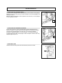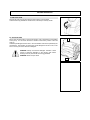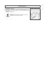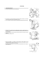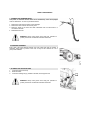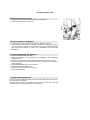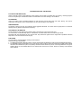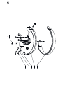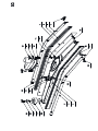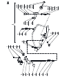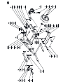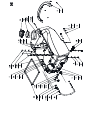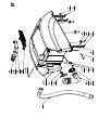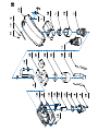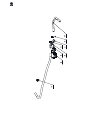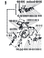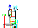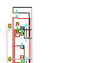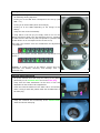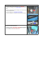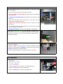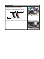
1
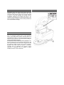
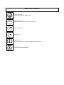
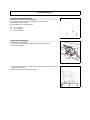
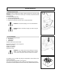
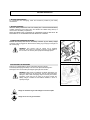
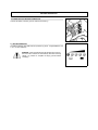
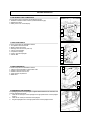
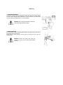
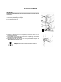
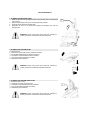
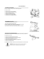
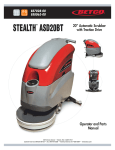
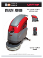
E87030-00 E88062-00 ™ STEALTH ASD20B 20” Automatic Scrubber with Brush Assist Operator and Parts Manual 1001 Brown Avenue • Toledo, Ohio 43607-0127 Customer Service: 888-GO-BETCO • Fax: 800-445-5056 • Technical Service: 877-856-5954 • www.betco.com 1 RECEIVING THE MACHINE Immediately check, when receiving the machine, that all the materials indicated on delivery documents have been received and also that the machine has not been damaged in transit. If it has been damaged, this damage must be immediately reported to the shipper and also to our customer’s service department. Only acting promptly in this manner will make it possible to receive missing material and to be compensated for damage. INTRODUCTION This is an automatic scrubber which, via the mechanical action of the rotating brush and the chemical action of a water/detergent solution, can clean any type of flooring. As it advances, it also collects the dirt removed and the detergent solution not absorbed by the floor. The machine must be used only for this purpose. Even the best machines will only work well if used correctly and kept in good working order. We therefore suggest you read this instruction booklet carefully and re-read it whenever difficulties arise while using the machine. If necessary, remember that our assistance and customer service (organized in collaboration with our dealers) is always available for advice or direct intervention. SERIAL # PLATE TECHNICAL DESCRIPTION Rated power Working width Rear squeegee width Work capacity Water consumption Brush & Pad (diameter) Brush RPM Brush pressure Brush motor Drive Type Vacuum motor Vacuum motor suction Solution tank capacity Recovery tank capacity Weight of machine (excluding batteries) Batteries Charger Battery compartment dimensions (Length / Height / Width) Machine dimensions (Length / Height / Width) Noise level Vibration level UM HP (W) In (mm) In (mm) ft2/h (m2/h) g/m2 ∅ in (mm) RPM lb (Kg) V / HP (V / W) V / HP (V / W) inches of water (mbar) Gal (l) Gal (l) lb (Kg) V / Ah V/A in x in x in (mm/mm/mm) in x in x in (mm/mm/mm) dBA ft/s2 (m/s2) 1.3 (950) 19.7 (500) 29.2 (742) 15,600 (1450) 38 19.7 (500) 140 51 (23) 24 / 0.54 (24 / 400) Semi-Auomatic 36 / 0.74 (36 / 550) 75.6 (188) 10.6 (40) 13.2 (50) 165 (75) 12 / 130 (2) 24 / 12 14.2 x 12.8 x 13.0 ((360 /325 /330) 45.3 x 39.4 x 20.9 (1150 / 1000 / 530) 58 2.5 (0.75) SYMBOLS USED ON THE MACHINE Solution valve symbol Used to indicate the water regulation switch Brush release symbol Used to indicate the button for automatic brush release Battery charge gauge Battery symbol Open book symbol Used to tell the operator to read the manual before using the machine Maximum solution temperature gauge Located near the solution tank inlet GENERAL SAFETY REGULATIONS The regulations below must be carefully followed in order to avoid harm to the operator and damage to the machine. Read all labels on the machine carefully. Do not cover them for any reason and replace them immediately if they become damaged. The machine must be used exclusively by authorized and trained personnel. When operating the machine be careful of other people and of children in particular. The machine is not suitable for cleaning carpets. The power cable outlet must be provided with a proper ground. Avoid damaging the power cable or the battery charger by crushing, bending or stressing it. Whenever the power cable of the battery charger is damaged, immediately contact a BETCO service center. Do not mix different types of detergent as this may produce harmful gases. Do not set containers of liquid on the machine. Machine storage temperature is between -10°F and 130°F, never store outside under humid conditions. Operating conditions: room temperature between 32°F and 100°F with relative humidity between 30% to 95%. Only use the machine in closed areas and do not expose it directly to rain. Never use the machine in an explosive environment. Do not use the machine as a means of transport. Never use acid chemicals which could damage the machine. Avoid running the brushes with the machine stopped: this could damage the floor. Never vacuum up flammable liquids. Never use the machine to gather dangerous powders. Use a powder fire extinguisher in case of fire. Do not use water. Do not hit against shelving or scaffolding when there is a chance of falling objects. The operator must always be equipped with the appropriate safety device (gloves, shoes, helmet, glasses, etc.) Do not use the machine on surfaces with an inclination greater than the one shown on the plate. The machine is designed to wash and dry floors simultaneously. Different operations should only be carried out in areas where passage of unauthorised people is prohibited. Signal the presence of wet floors with suitable signs. If the machine does not work properly, check this is not caused by failure to carry out routine maintenance. Otherwise, request the intervention of the BETCO technical assistance center. When replacing parts ask for ORIGINAL spare parts from your Authorized BETCO Dealer and/or Retailer. Always switch off the machine and disconnect the battery connector whenever maintenance is performed. Never remove guards that require tools for removal. Never wash the machine with direct or pressurized jets of water or with corrosive substances. Have your BETCO service center check the machine once a year. To prevent the formation of scale in the solution tank filter, do not fill the tank with detergent solution hours before using the machine. Before using the machine make sure that all doors and covers are positioned as shown in this operating and maintenance manual. Dispose of consumables in accordance with existing laws and codes. When your BETCO machine is ready to be retired its entire component materials must be disposed of properly. They contain oils and electronic components. The machine itself was built using totally recyclable materials. Use only brushes furnished with the machine or those specified in the user's manual (page 19). Use of other brushes can compromise safety. When removing the battery, unplug the battery connection, unplug the charger and disconnect the battery terminals. Before recycling the machine, remove the battery. The battery and the battery charger must be disposed of in accordance with existing laws and codes. The machine is not intended for use by children and people with reduced physical, sensorial or mental capabilities, or lack of experience and knowledge, unless they have been given supervision or instruction concerning the use of the machine by a person responsible for their safety. Children must be supervised to ensure that they do not play with the machine. MACHINE PREPARATION 1. HANDLING THE PACKED MACHINE The machine is contained in specific packaging. It is not possible to place more than two packages on top of each other. The total weight is 220 lb (100kg). The overall dimensions of the package are: A: B: C: 45.1 in (1145mm) 26.2 in (665mm) 48.4 in (1230mm) 2. UNPACKING THE MACHINE 1. Remove the outer packaging 2. The machine is fixed to the pallet with wedges which block the wheels 3. Remove these wedges 4. Use a ramp to get the machine down from the pallet, pushing it backwards. Avoid violent blows to the base 5. Keep the pallet for any future transport needs MACHINE PREPARATION 3. BATTERY INSTALLATION The machine will be supplied with a battery charger and either two 12V Wet or AGM batteries. The batteries must be housed in the battery tray in the battery compartment beneath the recovery tank. To insert the batteries you must: 1. Lower the squeegee and base 2. Open the rear hinge that secures the tank 3. Rotate the recovery tank as far as it will go, using the side handle 3 WARNING: To avoid acid spillage you can use sealed batteries. 2 WARNING: Perform one battery charging cycle before using the machine. 4. TYPE OF BATTERY To power the machine you can use: • Wet batteries • AGM batteries • Gel batteries OTHER TYPES MUST NOT BE USED. The maximum dimensions and the weight are: Width 6.7 in (171mm) Length 12.9 in (329mm) Height 9.6 in (245mm) Weight 68 lb (31kg) WARNING: Your charger must be set according to the type of battery you install. Call BETCO customer service to ensure correct charger setting after replacement batteries are installed. The batteries must be handled using lifting and transportation means suitable for the weight and dimensions. They must be lifted by the handles on the upper part. They must be connected together in series, to obtain an overall voltage of 24V on the lugs. The electrical connection operations must be carried out by certified trained personnel. MACHINE PREPARATION 5. BATTERY MAINTENANCE For maintenance and recharging, follow the instructions provided by the battery manufacturer. 6. BATTERY DISPOSAL When the battery reaches the end of its working life, it must be disconnected by certified professional, then lifted (using the handles and suitable lifting device) to remove it from the battery compartment. DEAD BATTERIES ARE CLASSIFIED AS HAZARDOUS WASTE AND MUST BE DISPOSED OF AT AUTHORIZED BATTERY DISPOSAL COMPANY. 7. CONNECTING THE BATTERY CHARGER Beneath the recovery tank there is the battery connector (2), the battery charger connector must be plugged into. Disconnect the battery plug and plug the charger into the machine plug. WARNING: This process must be carried out by qualified personnel. The incorrect or imperfect connection of the cables to the connector can seriously harm people and damage objects. 8. RECHARGING THE BATTERIES Perform one complete battery charge cycle before using the machine. Avoid totally discharging the battery! This can cause permanent damage to it. Recharge as soon as the battery discharged signal light starts to flash. WARNING: Never leave the batteries completely discharged, not even if the machine is not being used. This can cause permanent damage to them. While recharging, keep the recovery tank raised, supporting it with the prop as shown in the figure. Ensure the battery charger is suitable for the batteries installed, in terms of capacity and type. Danger of inhalation of gas and leakage of corrosive liquids. Danger of fire: do not go near flames. 2 MACHINE PREPARATION 9. CONNECTING THE BATTERY CONNECTOR Connect the battery connector (2) to the machine connector (1) 1 2 11. BATTERY INDICATOR The battery indicator uses LEDs and has 8 positions (7 yellow - charged batteries, and 1 red - run down batteries). WARNING: a few seconds after the red indicator light comes on, the brush motor switches off automatically. With the remaining charge it is possible to complete the drying process before recharging. MACHINE PREPARATION 12. INSTRUMENT PANEL COMPONENTS The instrument panel components are identified as follows: 1- Paddles to activate brushes / traction (located beneath the grip) 2- ON/OFF key switch 3- battery level / hour-counter display 1 2 13. REAR COMPONENTS The rear components are identified as follows: 1- Foot pedal to raise the brushes 2- Water / solution level hose 3- Drainage hose with recovery tank cap 4- Latch to close the tanks 5- Compartment storage 6- Lever to raise the squeegee 7- Solution filter 3 3 5 4 2 6 1 7 14. SIDE COMPONENTS The side components are identified as follows: 1- Valve for manual regulation of clean water outlet 2- Handle to raise the recovery tank 3- Handle to raise the vacuum unit 4- Upper storage compartment 5- Brake lever 4 3 2 1 5 15. ASSEMBLING THE SQUEEGEE For packaging reasons, the squeegee is supplied dismounted from the machine, and must be assembled as follows: 1- Insert the two small pins of the squeegee in the appropriate holes on the squeegee support; 2- Insert the two cotter pins chained to the squeegee; 3- Plug the squeegee hose in the appropriate sleeve of the squeegee nozzle. MACHINE PREPARATION 16. ADJUSTING THE SQUEEGEE HEIGHT The height of the squeegee must be adjusted based on wear and tear of the squeegee blade. To do this, turn the knobs (2) counter clockwise to raise the squeegee, and clockwise to lower it. Note: the right and left wheels must be adjusted to the same level, so the squeegee can work parallel to the floor. 2 17. ADJUSTING THE SQUEEGEE INCLINATION During working operation, the rear squeegee blade is slightly tilted backwards (by about 0.2 in (5mm) in a uniform way for its entire length. If it is necessary to increase the bend of the squeegee blade in the central part, you must tilt the squeegee backwards, rotating the adjuster (1) counter clockwise. To increase the bend of the squeegee blade at the sides of the squeegee, rotate the adjuster clockwise. When fully adjusted, tighten the jam nut. 1 18. RECOVERY TANK Check the drain hose cap (on the rear of the machine) to ensure it’s closed. MACHINE PREPARATION 19. SOLUTION TANK Remove the front inlet cap and check the solution filter is correctly fitted. Check the filter cap (beneath the solution tank, at the back) is correctly closed. 20. SOLUTION TANK Fill the tank with clean water in the front fill location (1) at a temperature not exceeding 120°F (50°C). You can check the level of solution in the tank by means of the rear hose (2). Add the liquid detergent into the tank, in the concentration and manner specified by the manufacturer. The formation of excess foam could damage the vacuum motor, so be sure to use only the correct amount of detergent. 1 WARNING: Always use low-foam detergent. Introduce a small amount of anti-foam detergent in the recovery tank before starting to work to prevent foam from being generated. WARNING: Never use pure acids. 2 MACHINE PREPARATION 22. ASSEMBLING THE BRUSH 1. With the base up, insert the brush and position it in line with the plate beneath the base. 2. Lower the base, turn the key (1) to position “1”, push the paddles (2) on the handlebars. At this point, the brush is fixed. 2 2 WARNING: Make sure there are no objects or people in the vicinity of the brush when doing this operation 1 OPERATION 1. MACHINE OPERATION 1. Connect the battery plug (1) to the machine plug 2. Turn the key (1) of the main switch to the "ON" position (clockwise). The battery charge level indicator lights will immediately come on. 3. Turn on the water valve (2) (the water falls automatically while the brushes are turning). 1 2 4. Release the lever (3) and lower the scrubbing head. If the floor is particularly dirty, you can apply an overpressure to the scrubbing head by raising the pedal (3) until the lock down is triggered. 5. Lower the squeegee, turning the lever (4) counter clockwise. The vacuum motor will switch on. 6. Check that the brake (5) is off. 5 4 3 7. Pressing the paddles (1), activates the brushes and the machine begins to move (model with traction). During the first feet, check the amount of solution is correct, and that the squeegee dries the floor perfectly. 8. The machine will now start to scrub and dry until the solution tank is empty or recovery tank is full. 1 OPERATION 3. FORWARD MOVEMENTS The traction of these machines is obtained by means of the pad which, working slightly inclined, is able to drag the machine forwards. To move the machine, you must use the key then activate the paddles levers (1) on the handlebars. WARNING: when making even brief reverse movements, check the squeegee and base are raised. 4. OVERFLOW DEVICE The machine has a float in the filter basket that trips when the recovery tank is full to stop airflow into the vacuum hose. At this point you must empty the recovery tank by removing the cap of the rear drainage hose. WARNING: Always wear gloves when doing this operation to protect you from contact with hazardous chemicals. 1 SHUTTING DOWN THE MACHINE 1. AT THE END Proceed as follows when shutting down the machine and before you perform any type of maintenance: 1. 2. 3. 4. 5. Turn off the valve using its handle (1) Raise the brush deck using the pedal (2) Raise the squeegee using the lever (3) Turn off the key switch (4) Move the machine where the tanks can be drained 4 3 2 1 6. Remove the drainage hose from its compartment, unscrew the drainage cap and empty the recovery tank. 7. The squeegee must be raised when the machine is not operating, in order to avoid deforming the squeegee blade blades. 8. Disassemble the pads and clean them with water (to disassemble the pads, see “DISASSEMBLING THE PAD” below). WARNING: Always wear gloves when doing this operation to protect you from contact with hazardous chemicals. DAILY MAINTENANCE 1. CLEANING THE RECOVERY TANK 1. Raise the vacuum cover (1) and prop it open using the lifting rod on the right-hand side of the lid. 2. Remove the drainage hose (2) from its fitting and empty the tank. 3. Rinse the inside of the tank well with water. 4. Reposition the cover on the machine and replace the drainage hose cap and drainage hose. 1 WARNING: Always wear gloves when doing this operation to protect yourself from contact with hazardous chemicals 2 2. CLEANING THE VACUUM FILTER 1. Raise the cover. 2. Remove the vacuum filter cover by rotating it clockwise. 3. Pull the filter straight away from the lid to remove it. 4. Use water to clean the walls and base of the filter. 5. Carry out the cleaning operations carefully. 6. Reassemble all the elements. WARNING: Always wear gloves when doing this operation to protect yourself from contact with hazardous chemicals 3. CLEANING THE VACUUM HOSE FILTER 1. Raise the vacuum cover. 2. Rotate the inner filter (1) and remove it. 3. Use water to clean the walls and base of the filter. 4. Carry out the cleaning operations carefully. 5. Reassemble all the elements. WARNING: Always wear gloves when doing this operation to protect yourself from contact with hazardous chemicals 1 DAILY MAINTENANCE 4. CLEANING THE SQUEEGEE Ensure the squeegee is always clean, for better drying results. To clean it you must: 1. 2. 3. 4. 5. 6. Remove the hose from the squeegee Loosen the knobs (1) at the hose nozzle Remove and clean the nozzle Carefully clean inside the squeegee Carefully clean the squeegee blades Reassemble all the squeegee assembly 1 5. DISASSEMBLING THE PAD To disassemble the pad, proceed as follows: 2 1. Turn on the machine with the key switch 2. Press the pedal that raises and lowers the base, and keep it pressed 3. Press the paddles (2) then release them immediately 4. Upon release, the brush will be automatically release from the base 1 6. REPLACING THE SQUEEGEE BLADES Check the state of wear and tear of the squeegee blades and, if necessary, replace them. To replace them you must: 1. 2. 3. 4. 5. 6. Remove the squeegee hose from the nozzle Remove the cotter pins that fix the pins of the squeegee Disassemble the squeegee from its support Loosen the wing nuts by two turns (1) Remove the squeegee band clamp and squeegee blade Replace the squeegee blades To reassemble the squeegee, repeat the above-mentioned operations in the reverse order. WARNING: Always wear gloves when doing this operation to protect yourself from contact with hazardous chemicals 1 WEEKLY MAINTENANCE 1. CLEANING THE SQUEEGEE HOSE Every week, or whenever vacuum seems to be unsatisfactory, check the squeegee hose for obstructions. To clean it, proceed as follows: 1. Remove the hose from the sleeve on the squeegee 2. Remove the other end from the recovery tank 3. Wash the inside of the hose with water introduced from the side where it is connected to the tank 4. Reassemble the hose WARNING: Always wear gloves when doing this operation to protect yourself from contact with hazardous chemicals 2. CHECKING THE BRAKE Every week, check the distance between the work brake pads and the wheels. If necessary, adjust them by means of the nuts, so they are at a distance of 0.12 in (3mm) when released. 3. CLEANING THE SOLUTION TANK 1. Loosen the solution tank cap. 2. Rinse with water. 3. Loosen the drainage cap (1) located on the filter, and empty the tank. WARNING: Always wear gloves when doing this operation to protect yourself from contact with hazardous chemicals 1 TROUBLESHOOTING GUIDE INSUFFICIENT WATER ON THE PAD 1. Check the valve – located beneath the symbol – (1) is turned on. 2. Check there is water in the solution tank. 1 THE MACHINE DOES NOT CLEAN WELL 1. Check the state of wear and tear of the pad and, if necessary, replace it. 2. Use a different kind of pad to the one fitted as standard. For cleaning floors where the dirt is particularly resistant, we recommend the use of special brushes supplied upon request and according to needs (see “CHOOSING AND USING THE BRUSHES”). THE SQUEEGEE DOES NOT DRY PERFECTLY 1. Check the squeegee blades are clean. 2. Adjust the inclination of the squeegee (see "SQUEEGEE" under “MACHINE PREPARATION”) 3. Ensure the vacuum hose is correctly inserted in its housing on the recovery tank. 4. Check the inner filter of the recovery tank to ensure it is not dirty and, if necessary, clean it thoroughly. 5. Disassemble the entire vacuum unit and clean it. 6. Replace the squeegee blades, if worn. 7. Ensure the vacuum motor switch is turned on. 8. Check wheel adjustment. TOO MUCH FOAM IS GENERATED Check that low-foam detergent is being used. If necessary add a small amount of antifoam liquid to the recovery tank. Remember that more foam is generated when the floors are not very dirty. Dilute the detergent more when cleaning floors that are not very dirty. CHOOSING AND USING THE BRUSHES POLYPROPYLENE BRUSH (PPL) Used on all types of floors. Good resistance to wear and tear, and hot water (no greater than 140°F (60°C)). The Polypropylene brush is non-hydroscopic and therefore retains its characteristics even when working in wet conditions. NYLON BRUSH Used on all types of floors. Excellent resistance to wear and tear and hot water (even over 140°F (60°C)). The nylon is hydroscopic and it tends to lose its characteristics over time when working in wet conditions. ABRASIVE BRUSH The bristles of this type of brush are coated with highly aggressive abrasives. It is used to clean very dirty floors. To avoid floor damage work only with the head pressure necessary. THICKNESS OF THE BRISTLES Thicker bristles are more rigid and are therefore used on smooth floors or floors with small joints. On uneven floors or those with deep joints, it is advisable to use softer bristles which can enter the gaps easier. Remember that when the bristles are worn and too short, they will become rigid and are no longer able to penetrate and clean deep down. In this case the brush tends to jump. PAD DRIVER The pad holder is recommended for cleaning smooth surfaces. There are two types of pad holder: 1. The traditional pad holder is fitted with a series of anchor points that allow the abrasive floor pad to be held and dragged while working 2. The CENTER LOCK type pad holder not only has anchor points, but also a snap-type central locking system made of plastic that allows the abrasive floor pad to be perfectly centered and held without any risk of it becoming detached. This type of dragging device is recommended above all for machines with more than one brush, where the centering of the abrasive discs is difficult. Item Number 1 2 3 4 5 6 Part Number E88272 E20073 E83970 E83802 E81709 E83404 Description Brush Deck Splash Guard Brush Deck Bushing Hex Bolt M8x30 Zinc Nyloc Hex Nut, M8 Zinc Flat Washer M9x24x2.5 Zinc QTY. 1 1 3 3 3 8 Item Number 1 2 3 4 5 6 7 8 9 10 11 12 13 14 15 16 17 18 19 19.11 19.12 20 21 23 24 25 26 27 28 29 30 31 32 33 34 Part Number E20011 E82312 E83833 E83404 E81709 E83895 E83524 E81918 E81874 E83830 E82309 E83331 E83547 E82774 E20093 E20297 E82844 E82845 E88235 E20451 E81694 E83565 E20418 E83491 E83881 E88010 E83489 E20290 E20507 E20584 E20358 E86169 E83823 E20592 E83672 Description Motor Mount Plate Bushing Hex Bolt M8x25 Zinc Flat Washer M9x24x2.5 Zinc Nyloc Hex Nut, M8 Zinc Wheel 80 OD x 23 W Bushing Flat Washer M9x32x2.5 Zinc Flat Washer M8x17x1.6 Zinc Hex Bolt M8x40 Zinc Spring, Compression Knob Hex Bolt M6x16 Zinc Flat Washer M6x12x1.6 SS Carriage Bolt M8x25 Zinc Flat Hd Soc Machine Screw M8x16 Zinc Clutch Plate Spacer Brush Drive Gear Motor 24VDC 400W Solution Tube Shaft Key Knob Clutch Coupling Spring Hex Bolt M5x20 Zinc Hex Nut, M5 Rings Flat Hd Soc Machine Screw M5x16 SS Brush Deck Retainer Set Screw Hex Soc Cone Point M5x12 Zinc Band Clamp Screw M5x20/ SS Custom Dowel Pin M8 Hex Jam Nut, M8x5 SS QTY. 1 2 2 2 6 2 2 2 4 2 2 1 4 4 1 3 1 3 1 1 1 1 1 1 1 4 1 2 1 1 2 1 1 1 1 Item Number 1 2 3 4 5 6 7 8 9 10 11 12 13 14 15 16 17 18 19 20 21 22 23 24 25 Part Number E82665 E81809 E83327 E83417 E83326 E81633 E83591 E82451 E82253 E82307 E83971 E83810 E82707 E83945 E83911 E83590 E83851 E83914 E81848 E83802 E20114 E82775 E83875 E81874 E81918 Description Squeegee Shoe Band Clamp Squeegee Blade, Front Squeegee Blade, Central Shore 33 Squeegee Blade, Rear Band Clamp Knob Wheel 45 OD x 25 W Bushing Squeegee Vacuum Adapter Gasket Knob Set Screw Hex Soc Flat End M6x40 SS Stud Bolt M10x33 Custom Stud Bolt M10x46 Custom Chain Screw, Pan Hd Phil Self Tap M5.5x13 SS Hex Bolt M6x20 SS Flat Hd Soc Machine Screw M6x25 SS Hex Bolt M8x30 Zinc Hex Jam Nut, M6X3 SS Nyloc Hex Nut, M6 SS Hex Jam Nut, M10X6 Zinc Flat Washer M8x17x1.6 Zinc Flat Washer M9x32x2.5 Zinc QTY. 1 1 1 1 1 1 6 2 2 1 1 2 2 1 1 1 1 4 6 2 14 4 2 2 2 Item Number 1 2 3 4 4.1 4,1,1 4,1,2 4,1,3 4,1,4 4,1,5 4,1,6 4,1,7 4,1,8 4,1,9 4,1,10 4,1,11 4,1,12 4,1,13 4.2 4.3 4.4 4.5 4.6 5 6 7 8 9 10 11 12 13 14 15 16 Part Number E82279 E88279 E20373 E20227 E20644 E85497 E82329 E82428 E81634 E82273 E85498 E20246 E83656 E83550 E82798 E81874 E85722 E83531 E83590 E83655 E20286 E85499 E20134 E20408 E20242 E83838 E82317 E83875 E81673 E83550 E88248 E20382 E20638 E88250 E20641 Description Spring Micro Switch Sealed Guide Bushing Squeegee Yoke ASM Squeegee Wheel Support ASM Weldment, Squeegee Wheel Support Threaded Pin Wheel 52 OD x 28 W Spring Compression Bushing E Style Circlip Flat Hd Soc Machine Screw M6x50 Zinc Hex Nut, M8x6.5 Zinc NyLoc Hex Nut, M6 Zinc Flat Washer M6x18x1.5 Zinc Flat Washer M8x17x1.6 Zinc Flat Washer M13x24x2.5 Zinc Knob Chain Adjuster Knob Squeegee Yoke Hex Nut, M8x6.5 SS Hex Bolt M5x10 Zinc Squeegee Lift Lever Pan Hd Phil Machine Screw M3x20 Zinc Screw 4.2 X 13 Hex Jam Nut, M5X3.5 Zinc Hex Jam Nut, M10X6 Zinc Hex Nyloc Nut, M3 Zinc NyLoc Hex Nut, M6 Zinc Spring 17 x 14 x 53 Wide D=1.5 Nyloc Hex Nut, M5x5 Zinc Knob Squeegee Lift Cable Bracket QTY. 1 1 1 1 2 1 1 1 1 1 1 1 1 1 1 1 1 1 1 1 1 1 1 1 2 4 1 1 2 1 1 2 1 1 1 Item Number 1 2 3 4 5 6 7 8 9 10 12 13 14 15 16 17 18 20 20.1 20.2 20.3 20.4 20.5 21 22 23 24 26 27 28 29 30 31 32 33 34 35 Part Number E82834 E20437 E81735 E83829 E83550 E81627 E81948 E20647 E81738 E20388 E83597 E83669 E20370 E82761 E20226 E20334 E85722 E20430 E20600 E83833 E82807 E81874 E20532 E20501 E20122 E20116 E20488 E20473 E20435 E20242 E82551 E88256 E20380 E82773 E20246 E20255 E20528 Description Pivot Block Castor Hex Bolt M12x35 Zinc Hex Jam Nut, M12X7 Zinc NyLoc Hex Nut, M6 Zinc Nyloc Hex Nut, M16 Zinc Flat Washer M20x26x1.5 AL Axle Shaft Flat Washer M4x12x3 Zinc Brush Deck Lift Arm Weldment Brush Deck Lift Idler Arm Weldment Pedal cover Foot Pedal Flat Washer M6x12x1.6 Zinc Bumper Bumper Flat Washer M13x24x2.5 Zinc Main Frame ASM Main Frame Weldment Hex Bolt M8x25 Zinc Nyloc Hex Jam Nut, M8 Zinc Flat Washer M8x17x1.6 Zinc Axle Mounting Bracket Splash Guard Flat Washer M5x15x1.5 SS Nyloc Hex Nut, M5x7 SS Carriage Bolt M5x16 Zinc Switch Plate Nyloc Hex Nut, M3 SS Pan Hd Phil Machine Screw M3x20 Zinc Transport Wheel 175 OD x 45 W Micro Switch Soc Hd Cap Screw M12x30 Zinc Flat Washer M10x21x2 Zinc Flat Hd Soc Machine Screw M6x50 Zinc Flat Hd Soc Machine Screw M6x45 Zinc Spacer QTY. 6 1 1 1 8 2 2 2 1 1 1 1 1 6 1 1 2 1 1 2 2 4 1 1 2 2 2 1 2 2 2 1 2 1 2 4 2 Item Number 1 1.1 1.1 1.12 1.12.2 1.12.3 1.12.4 1.13 1.14 1.15 1.16 1.17 1.2 1.3 1.4 1.5 1.6 1.7 1.8 1.9 2 3 4 5 6 7 8 9 10 11 12 13 14 15 Part Number E20285 E82429 E20569 E20197 E20389 E20196 E20271 E20611 E20577 E20606 E86145 E20110 E82612 E88259 E88261 E83930 E83361 E83601 E20107 E20409 E82772 E20090 E82774 E82798 E20438 E20392 E81619 E20468 E88260 E20112 E88258 E83935 E20411 E20538 Description Solution Tank ASM Cap Flat Hd Soc Machine Screw M5x16 Zinc Solution Tank ASM Hinge Pin Barbed Nipple Grommet Guard Plate Spacer Spacer Knob Flat Hd Soc Machine Screw M5x25 SS Filter Filter, Water 23 x 53 Plug 3/4" Flat Washer M8.2x32x4 Zinc Pipe Nipple, 3/8 in. Ball Valve Barbed Nipple Screw, Pan Hd Phil Self Tap M4.2x16 SS Foot Pedal Latch Plate Hex Bolt M6x20 Zinc Hex Bolt M6x25 Zinc Flat Washer M6x12x1.6 SS Flat Washer M6x18x1.5 Zinc Bezel Pan Hd Phil Machine Screw M4x16 Zinc Support Bracket Flat Hd Phil Machine Screw M5x12 Zinc Lanyard Hex Nut, M6x6 Zinc Hose, Glass Reinforced 15 OD x 10 ID x 496 L Hose Clamp Bracket Battery Tray QTY. 1 1 3 1 1 2 2 1 1 1 1 2 1 1 1 1 1 1 2 1 2 3 4 6 1 4 1 1 1 1 1 2 1 1 Item Number 1 2 3 3.1 3.2 3.3 3.4 3.5 3.6 3.7 3.8 3.9 3.1 3.11 3.11.2 4 5 6 7 8 9 Part Number E12666 E20074 E20354 E20189 E20186 E88285 E88286 E20413 E20107 E20432 E20468 E81619 E82341 E20198 E20188 E83833 E82638 E82808 E20127 E20563 E20195 Description Squeegee Vacuum Hose Hinge Pin Recovery Tank ASM Barbed Nipple Elbow Filter, Cage Hose, Drain Latch Screw, Pan Hd Phil Self Tap M4.2x16 SS Hose Clamp Flat Hd Phil Machine Screw M5x12 Zinc Support Bracket Gasket Recovery Tank ASM Hinge Pin Hex Bolt M8x25 Zinc Screw, Pan Hd Phil Self Tap M3.9x13 SS Hex Jam Nut, M8X5 Zinc Flat Washer M9x18x1.5 Zinc Plate Plate QTY. 1 1 1 1 1 1 1 1 2 1 3 3 1 1 1 1 6 1 1 1 1 Item Number 1 1.1 1.10 1.11 1.12 1.13 1.14 1.15 1.16 1.17 1.18 1.19 1.2 1.20 1.21 1.22 1.23 1.24 1.25 1.26 1.27 1.3 1.4 1.5 1.6 1.7 1.8 1.9 2 3 Part Number E20066 E20599 E88292 E20442 E20613 E20652 E20325 E20199 E20384 E20486 E20266 E20178 E88290 E20179 E20180 E20181 E20182 E20183 E20184 E20191 E20305 E20064 E20440 E88289 E81006 E88200 E20105 E83796 E82638 E20265 Description Recovery Tank Cover ASM Vacuum Motor 24VDC 550W Filter, Cage Button Hd Soc Machine Screw M5x16 Zinc Pan Hd Phil Machine Screw M5x10 Zinc Sound Deadening Foam Hose Clamp Recovery Tank Cover Vacuum Motor Cover Bushing Sound Deadening Foam Sound Deadening Foam Hose, Vacuum Sound Deadening Foam Sound Deadening Foam Sound Deadening Foam Sound Deadening Foam Sound Deadening Foam Sound Deadening Foam Deflector Mounting Ring Support Bracket Sound Deadening Foam Gasket Vacuum Splash Guard Vacuum Motor 36VDC 550W Screw, Pan Hd Phil Self Tap M4.2x22 SS Screw, Pan Hd Phil Self Tap M4.2x16 Zinc Screw, Pan Hd Phil Self Tap M3.9x13 SS Plate QTY. 1 1 1 1 6 1 2 1 1 1 1 1 1 1 1 1 1 1 1 1 1 1 1 1 1 1 2 2 4 2 Item Number 2 4 5 6 7 8 9 Part Number E81035 E85762 E86275 E88265 E83935 E20375 E20602 Description Solenoid Valve Hose Clamp Barbed Elbow Hose, Glass Reinforced D 10 x 140 Hose Clamp Tubing 10 ID x 650 L Barbed Threaded Nipple QTY. 1 2 1 1 2 1 1 Item Number 1 2 2.1 2.2 2.3 2.4 2.5 3 3.1 3.2 3.3 3.4 3.5 3.6 3.7 3.8 3.9 3.1 3.11 3.12 3.13 3.14 3.15 3.16 3.17 3.18 3.19 3.2 3.21 4 5 6 7 8 9 10 11 12 13 14 15 16 17 18 19 20 21 22 23 24 25 26 26.1 26.2 27 27.1 27.2 27.3 27.4 27.5 Part Number E20200 E82351 E83316 E83316 E83315 E83173 E81358 E20223 E20360 E20574 E88204 E81763 E83550 E82798 E20330 E20382 E81625 E82317 E82270 E20243 E81673 E20341 E20248 E20556 E20242 E20365 E20466 E83037 E20362 E20111 E88267 E88300 E20242 E81673 E88301 W87296 E83836 E20121 E20400 E20192 E20267 E20288 E83704 E81874 E20346 E20442 E82317 E83838 E82772 E82798 E82761 E20463 E88293 E20332 E20336 E20374 E85788 E82317 E83899 E88266 Description Handlebar Housing Key Switch Key Switch Key Switch Switch Key Key Switch Contact Switch Flange Drive Control Hex Bolt M6x45 Zinc Bushing Spring Cam NyLoc Hex Nut, M6 Zinc Flat Washer M6x18x1.5 Zinc Pin Nyloc Hex Nut, M5x5 Zinc Ball Stud Receiver Hex Jam Nut, M5X3.5 Zinc Micro Switch Pan Hd Phil Machine Screw M3x30 Zinc Hex Nyloc Nut, M3 Zinc Hex Bolt M4x16 Zinc Hex Nut, M4x4 Zinc Plate Pan Hd Phil Machine Screw M3x20 Zinc Hex Nut, M3x2.5 Zinc Insert Flat Washer M4x12x1.6 Zinc Set Screw Hex Soc Dog Point M5x30 Zinc Flat Hd Soc Machine Screw M6x20 Zinc Switch Cam Lever, Left Switch Pan Hd Phil Machine Screw M3x20 Zinc Hex Nyloc Nut, M3 Zinc Lever, Right Switch Drain Hose Clip Hex Bolt M5x16 Zinc Flat Washer M5x15x1.5 Zinc Hinge CHIPBOARD SCREW M3x12 Zinc Door Soc Hd Cap Screw M8x30 Zinc Lock Washer M8x13x2.2 Zinc Flat Washer M8x17x1.6 Zinc Flat Hd Soc Machine Screw M8x25 SS Button Hd Soc Machine Screw M5x16 Zinc Hex Jam Nut, M5X3.5 Zinc Screw 4.2 X 13 Hex Bolt M6x20 Zinc Flat Washer M6x18x1.5 Zinc Flat Washer M6x12x1.6 Zinc Instrument Panel ASM Hour Meter Panel Electronics ASM Plate Electrical Housing Hex Jam Nut, M5X3.5 Zinc Pan Hd Phil Machine Screw M5x10 SS Relay Card QTY. 1 1 1 1 1 1 1 1 1 1 1 1 1 1 2 2 2 2 3 2 4 1 1 1 3 5 1 1 1 2 1 1 2 2 1 1 1 1 1 4 1 4 4 4 2 1 2 4 2 2 2 1 1 1 1 1 1 1 1 1 MI 1 MI 2 8 10 9 25 11 4 1 5 6 NC 6 OPTIONAL 11 7 3 4 17 7 12 NC 10 8 9 4 3 5 3 7 1 3 1 25 3 Rxe185 17 3 25 28 7 J11 J7 J8 23 29 J10 J9 14 16 16 15 12 23 26 24 24 16 27 14 15 1 28 28 29 25 NC MI 3 M2 NC MI 4 29 Item Number 1 2 10 11 14 15 16 MI 1 MI 2 MI 3 MI 4 M1 M2 Part Number E88293 E82351 E88266 E86208 E82322 E20402 E20402 E82270 E82270 E88249 E88249 E88235 E88291 Description Hour Meter Key Switch Relay Card SB50 Red Electrical Connector Solenoid Valve Electrical Connector 30A Electrical Connector 30A Micro Switch Micro Switch Micro Switch Micro Switch Brush Gear Motor 24VDC 400W Vacuum Motor 36VDC 550W 6 8 Rxe 185 5 1 5 2 3 4 D7 NC Rue 90 D1 DZ1 Rue 3x800 D4 MOTORE SPAZZOLA C1 ELETTROVALVOLA NC D3 D2 D6 Rue 900 D5 NC MOTORE ASPIRAZIONE C2 Rue 900 NC Electric harness inspection. 1. Verify the functionality and adjustment of the micro switches of the handle command. 2. Verify that the micro switches are pressed with the lever in rest position and that in that condition the micro switch lever has about 0.5mm of movement. 3. Verify the functionality and conditions af the power contactors of the self recovery fuses and of the connections of the control card. Battery Check Card – Hour Meter 1. Verify that turning on the machine the battery check card has the following starting sequence: - Turning on of the LED which correspond to the set-up (red LED = “0”). - Turning on of all the LEDs (check of the lamps) - Turning on of the LEDs depending on the charge of the battery 2. Verify the hour meter functionality To verify which is the set-up you simply need to turn on the machine and check which is the first LED that turns on. Counting the LEDs since the left side any LED correspond to a position and the LED which turn on correspond to the current set-up. Verify that if the machine uses wet cell batteries the adjustment is on position 1. Verify that if the machine uses GEL batteries the adjustment is on position 4. WARNING: A wrong set-up of the battery control card can compromise the battery efficiency and damage then in irreversible way. Hydraulic plant inspections 1. Fill up the solution tank and verify the sealing of the gasket particularly on the solution valve and on the drain plug. 2. Verify that the water distribution on the floor is even and dependent on the solution valve adjustment. 3. Check the internal cleanness of the water valve. If necessary clean it using a metal bar putted inside the threaded hole of the filter plug. 4. Verify the cleanness and functionality of the solution filter under the solution tank plug. Vacuum system inspection 1. Verify the cleanness and functionality of the float filter. 2. Check the air sealing of the vacuum head on the recovery tank. 3. Verify the connections and the sealing of the vacuum hoses and the squeegee hoses. 4. Check the sealing of the squeegee hose adapter. 5. Check the sealing of the exhaust hose and exhaust hose plug. 6. Vacuum micro switch adjustment: 7. Adjust the vacuum micro switch in way that when the cam on the squeegee lever push the micro switch there is about 0.5 mm of clearance of the micro switch lever. Brush base adjustment Verify the right inclination of the brush base. To adjust the brush base act as follow: • Lower the brush base on the floor with the brush. • Loosen the M8 bolt and the M8 nut that attach the brush base to the left arm. • Loosen the nut and the bolt that attach the brush base to the idler arm. • Verify that the brush base correctly lays on the floor and the brush touch completely the floor. • Tighten the nut and its M8 bolt to lock the left arm of the brush base. • Lift up the front side of the brush base to let it be 5 mm from the floor as regards the back side. • Tighten the M8 nut to secrue the brush base in this position. Check that the pan head screw on the back side is adjusted near the flat part of the brush. The distance between the screw head and the brush has to be 1-2 mm when the brush is locked and the brush base is lowered. In the machines without traction: • Loose the ring nut. • Adjust the knob to let the brush in working condition help the machine in going forward. (Tighten to increase the traction effect, loosen to decrease the traction effect). • When the right adjustment is reached, tighten the ring nut. Brake adjustment 1. Verify that the brake on the left hand wheel blocks the wheel when active. 2. Otherwise act as follow: • Unscrew the jam nut. • Loosen the pad screw to achieve the right adjustment. • Verify the adjustment with a functional test • Tighten the jam nut to assure a right adjustment. Squeegee adjustment 1. Adjust the inclination adjuster of the squeegee blade until the blade has a common inclination over its length. 2. Adjust the height of the wheels using the knob checking that the blade has an inclination between 30 and 45 degrees. Front Blade Rear Blade 45° 3. Verify the cleanness and sealing of the squeegee hose adapter. Functional check of the machine Check the functionality of switches; Check the functionality of the accelerator lever; Check the functionality of the brush base; Check the functionality of the brush motor; Check the functionality of the solenoid valve; Check the functionality of the vacuum motor; Check the functionality of the brakes; Check the functionality of batteries and power cables; Functional test of the machine Fill up the tanks completely and verify the sealing; Verify the sealing of all the water plant and that the water is equal on the brush; Adjust the inclination and the height of the squeegee blades doing a functional test; Adjust the inclination of the brush base and do a functional test; Check the efficiency of the parking brake; Verify the forward and backward movement, acceleration and braking; Final Check Check all the functions: washing, drying and movement BETCO US WARRANTY POLICY 10 year coverage 3 Year Coverage 1 Year Coverage Subject to the conditions stated below, Betco warrants parts and labor on rotationally molded polyethylene tanks/ housings and injection molded vacuum head assemblies to be free from defects in materials and workmanship for a period of ten years to the original purchaser. Subject to the conditions stated below, Betco warrants parts and labor on all other Betco components to be free from defects in materials and workmanship for a period of three years to the original purchaser. Subject to the conditions stated below, Betco offers a limited warranty on parts and labor on the following equipment: parts and accessories to be free from defects in materials and workmanship for a period of one year to the original purchaser. • DM Series Vacuums: #85506-00, #85507-00 • Bac Pac Lite Vacuum: #85903-00 • FiberPRO® Floor Dryer: #85507-00 • WORKMAN™ Series Vacuums: #85024-00, #85025-00, #85026-00, #85027-00 • CV100T Vacuum: #85023-00 • All Tools and Accessories • All Battery Chargers • All Batteries are pro-rated for 1 year Allowable Travel Time Warranty Reimbursement: Eligible equipment: All battery and propane powered equipment products. Warranty period: 90 days from date of sale to the original purchaser. A maximum 60 mile round trip at 44 cents per mile will be allowed for warranty consideration. Propane Machine Warranty: Honda engines are warranted by Honda for a period of 2 years against manufacturer defects. Kawasaki engines are warranted by Kawasaki for a period of 2 years against manufacturer defects. All other components (except wear items)* are warranted by Betco for a period of 3 years. *Wear Items exempt from Warranty consideration include but may not be limited to: power cords, transport wheels, vacuum bags, belts, squeegee blades, pad drivers, clutch plates, handle grips, filters, screens, throttle cables, brushes and carbon brushes. Subject to the conditions and exceptions stated in this warranty, Betco warrants the Betco products to be free from defects in material and workmanship, under normal use and service, for the periods listed under the warranty policy to the original purchaser. At any time during the warranty period, Betco will furnish replacement parts for the Betco parts to the original purchaser. Such parts will be furnished and charged including transportation costs, to the original owner through any Betco authorized Service Distributor. If the original part is returned within the warranty policy period from date of delivery for inspection by Betco and is found to be defective the owner will be credited for the cost of replacement parts plus shipping and handling. Replacement parts that have become defective through wear or abuse are not included in this warranty. This warranty does not apply to damage or defect caused by accident, misuse. Negligence, fire, or to any Betco product which has been serviced or repaired by other than an authorized Betco Service Distributor or Betco factory personnel. This warranty is void if products are used for any purpose other than that which was intended. There are no other warranties expressed or implied. In no event shall Betco be liable for incidental or consequential damages or any damage to person or property. (Please note some states do not allow the exclusion or limitations for incidental and consequential damages) 32 1001 Brown Avenue • Toledo, Ohio 43607-0127 Customer Service: 888-GO-BETCO • Fax: 800-445-5056 • Technical Service: 877-856-5954 • www.betco.com E87030-00 Sept09A