1
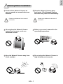
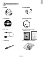
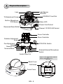
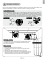
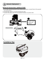
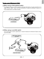
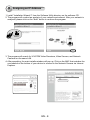
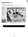
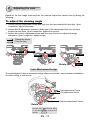
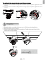
English
Warning Before Installation
Power off the Network Camera as
soon as smoke or unusual odors are
detected.
Contact your distributor in the event of
occurrence.
Keep the Network Camera away
from water. If the Network Camera
becomes wet, power off immediately.
Contact your distributor in the event of
occurrence.
Do not place the Network Camera
around heat sources, such as a
television or oven.
Refer to your user's manual for the
operating temperature.
Keep the Network Camera away from
direct sunlight.
Do not place the Network Camera in
high humidity environments.
EN - 1
Do not place the Network Camera on
unsteady surfaces.
Do not touch the Network Camera
during a lightning storm.
Do not disassemble the Network
Camera.
Do not drop the Network Camera.
Do not insert sharp or tiny objects
into the Network Camera.
EN - 2
English
1
Package Contents
FD8161
Power Adapter
Software CD
Alignment Sticker
510000210G
A/V Cable
Quick Installation Guide /
Warranty Card
Screwdriver
Screws and I/O Connector
EN - 3
2
Physical Description
Light Sensor
IR LEDs
Lens
SD/SDHC Card Slot
Tilt Adjustment Screw
Built-in Microphone
PIR Sensor
Status LED
Power Cord Socket
Recessed Reset Button
Ethernet 10/100 RJ45 Socket
Focus Controller
Zoom Controller
Rotation Adjustment
Screw
Pan Adjustment
Screw
General I/O
Terminal Block
NTSC/PAL Switch
Int. NTSC
ON
1 2
1 2 3 4
AV Out
Audio In
Ext PAL
Audio In
Audio/Video Out
External/Internal Microphone
Switch
Keep a note of the MAC address
before installing the camera.
Black Cover
Drill Holes
Network Camera
Model No: FD8161
Dome Cover
RoHS
C I
MAC:0002D107258A
This device complies with part 15 of the FCC rules. Operation is subject to
the following two conditions:
(1)This device may not cause harmful interference, and
(2) this device must accept any interference received, including interference
that may cause undesired operation.
Pat. 6,930,709
EN - 4
Made in Taiwan
English
3
Hardware Installation
First, use the supplied screwdriver to detach the dome cover from the camera base. Then,
follow the steps below to install the camera to either the ceiling or the wall.
Installation Tips
Before installing the camera, look for a shooting area that best suits your needs. The
built-in PIR (Passive Infrared) sensor will be triggered when a person enters its detection range. The sensitivity of PIR sensor depends on the object size and temperature
differences between the object and the background environment. Therefore, it is crucial
to install the camera at a place with the PIR sensor facing the desired direction.
AV Out
Audio In
Ext PAL
1 2
Side view
1 2 3 4
Top view
ON
Int. NTSC
Ceiling mount
Through the two holes on each side of the camera base, insert
the supplied two screws to corresponding holes and secure
them with a screwdriver.
Wall mount
1. Attach the alignment sticker to the wall.
2. Through the two circles on the sticker, drill two pilot holes
into the wall.
3. Hammer the supplied plastic anchors into the holes.
4. Align the two holes on each side of the camera base with the
two plastic anchors on the wall, insert the supplied screws to
corresponding holes and secure them with a screwdriver.
EN - 5
Alignment sticker
4
Network Deployment
General Connection (without PoE)
1. If you have external devices such as sensors and alarms, connect them to the general
I/O terminal block.
2. Connect the camera to a switch via Ethernet cable.
3. Connect the power cable from the Network Camera to a power outlet.
1
1: Power
2: Digital output
3: Digital input
4: Ground
Int. NTSC
ON
1 2
1 2 3 4
AV Out
Ethernet Switch
Audio In
POWER
Ext PAL
COLLISION
1
2
3
4
5
2
LINK
RECEIVE
PARTITION
3
Installation Tips
EN - 6
English
Power over Ethernet (PoE)
When using a PoE-enabled switch
This Network Camera is PoE-compliant, allowing transmission of power and data via a
single Ethernet cable. Follow the below illustration to connect the Network Camera to a
PoE-enabled switch via Ethernet cable.
POWER
COLLISION
1
2
3
4
5
LINK
RECEIVE
PARTITION
PoE Switch
When using a non-PoE switch
Use a PoE power injector (optional) to connect between the Network Camera and a
non-PoE switch.
PoE Power Injector
(optional)
POWER
COLLISION
1
2
3
4
5
LINK
RECEIVE
PARTITION
Non-PoE Switch
EN - 7
5 Assigning an IP Address
1. Install “Installation Wizard 2” from the Software Utility directory on the software CD.
2. The program will conduct an analysis of your network environment. After your network is
analyzed, please click on the “Next” button to continue the program.
Installation
Wizard 2
3. The program will search for VIVOTEK Video Receivers, Video Servers, and Network
Cameras on the same LAN.
4. After searching, the main installer window will pop up. Click on the MAC that matches the
one labeled on the bottom of your device to connect to the Network Camera via Internet
Explorer.
Network Camera
Model No: FD8161
00-02-D1-07-25-8A
RoHS
C I
MAC:0002D107258A
This device complies with part 15 of the FCC rules. Operation is subject to
the following two conditions:
(1)This device may not cause harmful interference, and
(2) this device must accept any interference received, including interference
that may cause undesired operation.
Pat. 6,930,709
192.168.5.151
0002D107258A
Made in Taiwan
EN - 8
FD8161
English
6
Ready to Use
1. Access the Network Camera on the LAN.
2. Retrieve live video through a web browser or recording software.
For further setup, please refer to the user's manual on the software CD.
EN - 9
7
Adjusting the Lens
Based on the live image retrieved from the camera, adjust the camera lens by doing the
following:
To adjust the viewing angle
1. Loosen the pan adjustment screw and then turn the lens module left and right. Upon
completion, tighten the screw.
2. Loosen the tilt adjustment screws on both side of the camera and then turn the lens
module up and down. Upon completion, tighten the screws.
3. Loosen the rotation adjustment screw and then turn the lens to adjust the image
orientation. Upon completion, tighten screw.
Rotate the screw
Turn the lens
Audio In
Ext PAL
1 2 3 4
AV Out
1 2
Audio In
Ext PAL
1 2
ON
1 2 3 4
AV Out
Audio In
Ext PAL
1 2
ON
Int. NTSC
ON
Int. NTSC
Int. NTSC
Tighten
AV Out
Loosen
Pan 350°
1 2 3 4
1
2
Loosen
Tighten
Loosen
3
Tilt 85°
Rotate 350°
Tighten
3-axis Mechanism Design
The sophisticated 3-axis mechanism design offers very flexible, easy hardware installation
for either ceiling or wall mount.
Pan 350°
Pan Adjustment Screw
Tilt Adjustment Screw
Tilt 85°
Rotation Adjustment Screw
Rotate 350°
DO NOT over rotate the lens. Doing
so will damage the camera lens
module
EN - 10
English
To adjust the zoom factor and focus range
1. Loosen the zoom controller to adjust the zoom factor. Upon completion, tighten the zoom
controller.
2. Loosen the focus controller to adjust the focus range. Upon completion, tighten the focus
controller.
1 2 3 4
AV Out
Audio In
Ext PAL
Loosen
1 2
ON
Int. NTSC
W
N
8
8
Tighten
T
Completion
1. Rotate the black cover inside the dome cover to fit the lens shooting direction.
2. Attach the dome cover to camera.
3. Secure the two dome screws with a screwdriver. Finally, make sure all parts of the
camera are securely installed.
3
2
The supplied screwdriver is exclusively
designed to match the dome screws. In case
you will need to adjust the lens later, do not
discard the screwdriver.
1
EN - 11