1
Installation Guide 111
2/26/2010
Eclipse Winnox
Burners
WX Series
Version 2
Copyright
Copyright 2005 by Eclipse, Inc. All rights reserved
worldwide. This publication is protected by federal
regulation and shall not be copied, distributed,
transmitted, transcribed or translated into any human or
computer language, in any form or by any means, to any
third parties, without the express written consent of
Eclipse, Inc.
Disclaimer Notice
In accordance with the manufacture’s policy of continual
product improvement, the product presented in this
brochure is subject to change without notice or obligation.
The material in this manual is believed adequate for the
intended use of the product. If the product is used for
purposes other than those specified herein, confirmation
of validity and suitability must be obtained. Eclipse
warrants that the product itself does not infringe upon any
United States patents. No further warranty is expressed or
implied.
Liability and Warranty
We have made every effort to make this manual as
accurate and complete as possible. Should you find errors
or omissions, please bring them to our attention so that we
may correct them. In this way we hope to improve our
product documentation for the benefit of our customers.
Please send your corrections and comments to our
Marketing Communications Manager.
It must be understood that Eclipse’s liability for its product,
whether due to breach of warranty, negligence, strict
liability, or otherwise is limited to the furnishing of
replacement parts and Eclipse will not be liable for any
other injury, loss, damage or expenses, whether direct or
consequential, including but not limited to loss of use,
income, or damage to material arising in connection with
the sale, installation, use of, inability to use, or the repair
or replacement of Eclipse’s products.
Any operation expressly prohibited in this Guide, any
adjustment, or assembly procedures not recommended or
authorized in these instructions shall void the warranty.
Document Conventions
There are several special symbols in this document. You
must know their meaning and importance.
The explanation of these symbols follows below. Please
read it thoroughly.
How To Get Help
If you need help, contact your local Eclipse representative.
You can also contact Eclipse at:
1665 Elmwood Rd.
Rockford, Illinois 61103 U.S.A.
Phone: 815-877-3031
Fax: 815-877-3336
http://www.eclipsenet.com
Please have the information on the product label available
when contacting the factory so we may better serve you.
www.eclipsenet.com
Product Name
Item #
S/N
DD MMM YYYY
Pat
This is the safety alert symbol. It is used to alert you to potential personal
injury hazards. Obey all safety messages that follow this symbol to avoid
possible injury or death.
Indicates a hazardous situation which, if not avoided, will result in death
or serious injury.
WARNING
Indicates a hazardous situation which, if not avoided, could result in
death or serious injury.
CAUTION
Indicates a hazardous situation which, if not avoided, could result in
minor or moderate injury.
NOTICE
NOTE
2
Is used to address practices not related to personal injury.
Indicates an important part of text. Read thoroughly.
Eclipse Winnox Burner, WX Series, V2, Installation Guide 111, 2/26/2010
Table of Contents
Introduction .............................................................................................. 4
Product Description....................................................................... 4
Audience ....................................................................................... 4
Winnox Documents ....................................................................... 4
Safety ........................................................................................................ 5
Introduction ................................................................................... 5
Safety ............................................................................................ 5
Capabilities.................................................................................... 5
Operator Training .......................................................................... 5
Replacement Parts........................................................................ 5
Installation ................................................................................................ 6
Introduction ................................................................................... 6
Handling & Storage ....................................................................... 6
Approvals of Components............................................................. 6
Checklist Before Installation.......................................................... 7
Installing the Flame Sensor........................................................... 7
Burner Mounting............................................................................ 7
Gas Piping..................................................................................... 9
Checklist After Installation............................................................. 10
Adjustment, Start & Stop......................................................................... 11
Step 1: Reset the system .............................................................. 11
Step 2: Set low fire air ................................................................... 12
Step 3: Ignite the burner................................................................ 13
Step 4: Set low fire gas ................................................................. 14
Step 5: Set high fire gas................................................................ 15
Step 6: Verify Settings................................................................... 15
Maintenance & Troubleshooting ............................................................ 16
Monthly Checklist .......................................................................... 16
Yearly Checklist ............................................................................ 16
Recommended Spare Parts.......................................................... 17
Troubleshooting ............................................................................ 17
Appendix................................................................................................... 19
Eclipse Winnox Burner, WX Series, V2, Installation Guide 111, 2/26/2010
3
1
Introduction
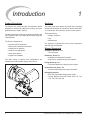
Product Description
Audience
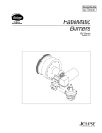
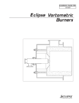
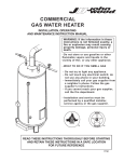
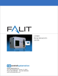
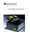
The Winnox is a nozzle-mix type, low-emissions burner
designed for direct and indirect air heating, and oven
applications up to 1800°F (980°C).
This manual has been written for people who are already
familiar with all aspects of a nozzle-mix burner and its addon components, also referred to as “the burner system”.
The burner package includes a combustion air blower and
ratio regulator to fire over a wide gas turndown range at a
controlled ratio.
These aspects are:
• Design / Selection
The burner is designed for:
• low NOX and CO emissions
• efficient ratio controlled combustion
• reliable burner operation
• simple burner adjustment
• direct spark ignition
• multiple fuel capability
The wide variety of options and configurations are
available due to the modular design of the burner.
• Use
• Maintenance
The audience is expected to have previous experience
with this type of equipment.
Winnox Documents
Installation Guide No. 111
• This document
Datasheet, Series 111
• Available for individual WX models
• Required to complete design and selection
Design Guide No. 111
• Used with Datasheet to design burner system
Spare Parts List, Series 111
• Recommended replacement part information
Related Documents
• EFE 825 (Combustion Engineering Guide)
• Eclipse Bulletins and Info Guides: 684, 710, 732,
742, 756, 760, 902, 930
Figure 1.1 Winnox Burner
4
Eclipse Winnox Burner, WX Series, V2, Installation Guide 111, 2/26/2010
2
Safety
Introduction
Capabilities
This section is provided as a guide for the safe operation
of a Winnox burner system. All involved personnel should
read this section carefully before operating this system.
Adjustment, maintenance and troubleshooting of the
mechanical and the electrical parts of this system should
be done by qualified personnel who has experience with
combustion equipment.
Safety
Operator Training
DANGER
Ŷ The Winnox burners are designed to mix fuel with
air and burn the resulting mixture. All fuel burning
devices are capable of producing fires and
explosions if improperly applied, installed,
adjusted, controlled, or maintained.
Ŷ Do not bypass any safety feature; fires and
explosions may result.
Ŷ Never try to light the burner if the burner shows
signs of damage or malfunctioning.
The best safety precaution is an alert and trained
operator. Train new operators thoroughly and have them
demonstrate an adequate understanding of the
equipment and its operation. A regular retraining schedule
should be administered to ensure operators maintain a
high degree of proficiency.
Replacement Parts
Order replacement parts from Eclipse only. All Eclipse
approved, customer supplied valves or switches should
carry UL, FM, CSA, CGA, and/or CE approval, where
applicable.
WARNING
Ŷ The burner might have HOT surfaces. Always wear
protective clothing when approaching the burner.
NOTICE
Ŷ This manual provides information in the use of
these burners for their specific design purpose. Do
not deviate from any instructions or application
limits described herein without written approval
from Eclipse.
Eclipse Winnox Burner, WX Series, V2, Installation Guide 111, 2/26/2010
5
3
Installation
Introduction
Gas Piping
In this chapter you will find information and instructions
needed to install the burner and system components.
All the gas piping must comply with all applicable local
codes and/or standards such as:
Handling & Storage
• NFPA Standard 54
Handling
• ANSI Z223
• Make sure that the area is clean.
Where to Get the Standards:
• Protect the components from excessive
temperatures and humidity.
The NFPA Standards are available from:
National Fire Protection Agency
Batterymarch Park
Quincy, MA 02269
www.nfpa.org
• Take care not to drop or damage components.
Storage
• Make sure that the components are clean and free
of damage.
• Store the components in a cool, clean, dry room.
• After you have made sure that everything is present
and in good condition, keep the components in the
original package as long as possible.
Approval of Components
Limit Controls & Safety Equipment
All limit controls and safety equipment must comply with
all applicable local codes and/or standards and must be
listed for combustion safety by an independent testing
agency. Typical application examples include:
• American: NFPA 86 with listing marks from UL, FM,
CSA
• European: EN 746-2 with CE mark from TuV,
Gastec, Advantica
Electrical Wiring
All the electrical wiring must comply with all applicable
local codes and/or standards such as:
• NFPA Standard 70
• IEC60364
• CSA C22
• BS7671
6
• EN 746-2
• Protect the components from the weather, damage,
dirt and moisture.
The ANSI Standards are available from:
American National Standard Institute
1430 Broadway
New York, NY 10018
www.ansi.org
The UL Standards are available from:
333 Pfingsten Road
Northbrook, IL 60062
www.ul.com
The FM Standards are available from:
1151 Boston-Providence Turnpike
PO Box 9102
Norwood, MA 02062
www.fmglobal.com/approvals
Information on the EN standards and where to get
them is available from:
Comité Européen de Normalisation
Stassartstraat 36
B-1050 Brussels
Phone: +32-25196811
Fax: +32-25196819
www.cen.eu
Comité Européen de Normalisation Electronique
Stassartstraat 36
B-1050 Brussels
Phone: +32-25196871
Fax: +32-25196919
www.cenelec.org
Eclipse Winnox Burner, WX Series, V2, Installation Guide 111, 2/26/2010
Checklist Before Installation
Intake
To admit fresh combustion air from outdoors, provide an
opening in the room of at least one square inch per 4,000
BTU/hr (1.17 kW). If there are corrosive fumes or
materials in the air, then supply the burner with clean air
from an uncontaminated area, or provide a sufficient air
filtering system.
For detailed information on how to install and connect a
flamerod, refer to Info Guide 832.
Installing the Spark Plug
Install the spark plug into the opening in the rear cover.
NOTE: Do not apply any grease to the threads of the
spark plug or bad grounding of the spark plug may occur,
resulting in a weak spark.
Exhaust
Do not allow exhaust fumes to accumulate in the work
area. Provide some positive means for exhausting from
the furnace and the building.
Access
Make sure that you install the burner in such a way that
you can gain easy access for inspection and
maintenance.
NOTICE
Ŷ If flame monitoring controls other than those
recommended in the Design Guide are used
contact Eclipse to determine how the burner
performance may be affected, adjustments may
vary from Eclipse published values. Consult with
the engineer who specified the alternate control
for limitations.
Environment
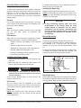
Burner Mounting
Make sure the local environment matches the original
operating specifications. Check the following items:
Chamber Opening
• Voltage, frequency and stability of the electrical
power
• Type and supply pressure of the fuel
• Availability of enough fresh, clean combustion air
• Humidity, altitude and temperature of air
• Presence of damaging corrosive gases in the air
Provide an opening in the chamber wall at least 1/2"
(12 mm) larger in diameter than the outside diameter of
the combustor (1/4" - 6 mm per side). The combustor
diameter can be found in the Winnox datasheet, series
111.
Provide an accessible pressure tap on the chamber wall
to measure the pressure inside the firing chamber. The
pressure tap should be located near the burner.
• Prevent direct exposure to water
Minimum 1/4" (6mm)
space per side
Installing the Flame Sensor
Slots
1. Install the flame sensor into the 1/2" NPT opening in the
rear cover.
2. Make sure that you connect the flame sensor of a
burner to the electrical circuit of that burner.
DANGER
Ŷ Connecting the flame sensor of a burner to the
electrical circuit of the wrong burner can result in
a fire or explosion.
There are two different types of flame sensors; UV
scanner and flame rod.
UV Scanner
The UV scanner must be compatible to the flame
monitoring control that is used. Refer to the manual of
your selected control for proper selection of the scanner.
Combustor
Chamber Wall
Figure 3.1 Chamber Opening
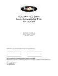
Mounting Pattern
Attach eight mounting bolts to the chamber wall. Position
these bolts to match the clearance holes (C) on the burner
mounting flange. Refer to Winnox datasheet, series 111.
“C”
Flame Rod
NOTE: Only specific burner sizes with alloy or silicon
carbide combustors can use a flame rod (see specific
burner datasheets).
Figure 3.2 Mounting Pattern
Eclipse Winnox Burner, WX Series, V2, Installation Guide 111, 2/26/2010
7
Tube Shrouding Considerations
1
Slots
3
Combustor
In applications where process air may flow perpendicular
over the combustor, a metal shroud should be installed
around the combustor that is 20% larger than the
combustor diameter with a length that covers the
combustor slots by 100 mm (4"). Slot dimensions can be
found in Winnox datasheet, series 111.
Chamber Wall
Fiber Insulation
Make sure the chamber wall Y is strong enough to
support the weight of the burner Z. If necessary, reinforce
the mounting area. See Figure 3.3.
NOTE: The slots in the combustor must not be covered
with insulation. If necessary, taper the chamber insulation
at a minimum of 45° to provide clearance for the
combustor slots. Slot dimensions can be found in the
Winnox datasheet, series 111.
1
Chamber
Insulation
2
Figure 3.4 Alloy Combustion Tube
Refractory Plug
When using the refractory plug the customer must provide
a refractory combustion tube. The customer is responsible
for supplying all refractory materials for combustion tube
field installation as follows:
1. Install the chosen refractory realizing it is essential that:
3
Chamber
Insulation
2
• The combustion tube dimensions are held as given
in the Winnox Datasheet series 111. See Figure 3.5.
• The inside diameter of the combustion tube is
concentric with the refractory plug.
Slots
Combustor
45° Minimum
Figure 3.3 Chamber Wall
Burner Mounting
Mount the burner to the chamber wall using eight (8)
customer supplied nuts and lock washers.
2. Support refractory combustion tube according to the
refractory supplier’s recommendations. The alloy
anchors should be coated with bitumastic whenever
they are used.
3. Fiber insulation must be installed between the
refractory plug and customer supplied refractory
combustion tube.
4. After the burner and refractory have been installed, a
proper curing schedule should be followed according
to refractory supplier’s recommendations.
Alloy Combustion Tube
1. Be sure gasket X is installed between burner Z and
chamber wall Y. See Figure 3.4.
2. Pack fiber insulation around the tube to a depth not
beyond the combustor slot position, as shown in
Figure 3.4.
Fiber
Insulation
Customer Supplied
Refractory
Combustion Tube
CAUTION
Ŷ Placing insulation over combustor slots will
impede burner performance and decrease
combustor life.
Refractory
Plug
90°
Figure 3.5 Refractory Plug
8
Eclipse Winnox Burner, WX Series, V2, Installation Guide 111, 2/26/2010
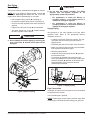
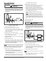
Gas Piping
CAUTION
Burner Piping
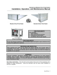
The burner is factory assembled and shipped as ordered.
NOTE: If it is necessary to redirect piping, remove the
outer four bolts only X. Rotate the rear cover and
replace bolts. When reassembling, be sure that:
Ŷ Do not alter the bypass regulator. The NFPA
requires that the bypass regulator ] be
appropriately vented and protected.
•
For applications in which the Winnox is
operating indoors, a vent limiting device is
installed in the bypass regulator.
•
For applications in which the Winnox is
operating outdoors, an insect/rain protector is
installed in the bypass regulator.
• ratio regulator spring column Y is pointing up
• the bypass regulator spring column is pointing up
• arrow on the ratio regulator points in the direction of
gas flow
• integral fuel orifice and o-rings Z are reinstalled
• the same straight run of pipe [ remains between
the ratio regulator and the burner.
CAUTION
Ŷ Do not attempt to redirect piping by removing the
inner circle bolts \. Internal burner parts will be
damaged.
Supply Piping
Inlet pressure to the ratio regulator must stay within
specified limits. Refer to the appropriate Winnox
datasheet, series 111.
• Locate the valve train close to the burner. The gas
must reach the burner during the fixed trial for
ignition period.
• Sufficiently size the shut off valve in the valve train.
• Make sure piping is large enough to accommodate
flow required to meet burner input.
• Minimize piping elbows.
• Install fuel flow measurement device X upstream
from the burner inlet.
• If necessary to maintain inlet pressures to the
burner (see datasheet for your burner), install a gas
pressure regulator Y upstream of the burner inlet
and downstream of the valve train and fuel
measurement device X.
Main gas
shut-off
valve train
Tap E
Figure 3.7 Supply Piping
Figure 3.6 Burner Piping
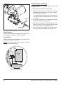
Pipe Connections
Installation of a pipe union in the gas line is recommended
to simplify burner removal.
Use of flexible pipe is optional.
NOTE: Flexible pipe causes higher pressure drops than
standard pipe. Consider this when sizing your gas lines.
Eclipse Winnox Burner, WX Series, V2, Installation Guide 111, 2/26/2010
9
Checklist After Installation
To verify the system was properly installed, perform the
following checks:
1. Be sure there are no leaks in the gas lines.
2. Be sure all the components contained in the flame
monitoring and control systems are properly installed.
This includes verifying that:
• all the switches are installed in the correct locations.
Bracket
• all wiring, pressure, and impulse lines are properly
connected.
3. Be sure all components of the spark ignition system
are installed and functioning properly.
4. Be sure the blower rotates in the proper direction. If the
rotation is incorrect, have a qualified electrician rewire
the blower to rotate in the proper direction.
Pipe
Union
5. Be sure all valves are installed in the proper location
and correctly oriented relative to the flow direction.
Figure 3.8 Pipe Connections
Piping Support
Use brackets or hangers to support the gas piping. If you
have questions, consult your local gas company.
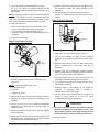
Control Motor
Install a control motor to modulate the air butterfly valve if
not factory installed on the burner.
NOTE: Be sure the control motor shaft and air butterfly
valve shaft are aligned properly.
BV
Shaft
Set
Screws
Motor
Shaft
Control
Motor
Coupling
Figure 3.9 Control Motor
10
Eclipse Winnox Burner, WX Series, V2, Installation Guide 111, 2/26/2010
Adjustment, Start &
Stop
In this chapter, you will find instructions on how to adjust,
start, and stop the burner system. Become familiar with
burner control methods before attempting to make
adjustments.
DANGER
Ŷ The Winnox burners are designed to mix fuel with
air and burn the resulting mixture. All fuel burning
devices are capable of producing fires and
explosions if improperly applied, installed,
adjusted, controlled, or maintained.
Ŷ Do not bypass any safety feature; fire or explosion
could result.
Ŷ Never try to light a burner if it shows signs of
damage or malfunction.
4
DANGER
Ŷ If simulated limits or simulated flame failure do not
shut down the fuel system within the required
failure response time, immediately correct the
problem before proceeding.
6. If the burner is firing into a duct or chamber with a
circulating fan, start the fan to produce full process air
flow past the burner.
7. Adjust main gas inlet pressure to the ratio regulator
within the range specified in the appropriate
datasheet.
WARNING
Step 1: Reset the System
Ŷ Gas inlet pressures must stay within the specified
range. Pressure above the specified range can
damage the ratio regulator.
1. Set the low gas pressure switch to 20% below the
“Fuel Inlet Pressure” range as specified in the
appropriate datasheet.
Ŷ Pressure below the specified range can impair the
ability of the ratio regulator to control the gas flow.
2. Set the high gas pressure switch to 20% above the
“Main Gas Inlet Pressure” range as specified in the
appropriate datasheet.
3. Close all the burner gas valves; manual and
automatic.
4. Try to ignite the burner; be sure the flame monitoring
system indicates a flame failure.
5. Activate the pressure switches and other limit
interlocks. Be sure the switches fail as intended in the
event of a power failure.
Eclipse Winnox Burner, WX Series, V2, Installation Guide 111, 2/26/2010
Ŷ Operating the system outside the specified range
can cause excess fuel consumption and the
possible accumulation of unburned fuel in the
chamber.
Ŷ In extreme cases, this accumulation of unburned
fuel may cause fires or explosions.
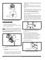
8. Verify the actuator opens the air butterfly valve
towards the back of the burner as shown in Figure 4.1.
If it doesn’t, refer to the actuator’s literature for
instructions on how to reverse the direction.
11
butterfly valve is closed when the shaft slot is
perpendicular to the direction of air flow through the
butterfly valve.
Back
b. Rotate the air butterfly valve shaft to a fully closed
position. (Holes in the butterfly valve will supply low
fire air.)
When firing into a positive chamber pressure, rotate
the air butterfly valve from the closed position in the
direction of actuator travel to obtain a minimum
0.3" w.c. (0,8 mbar) air differential pressure.
Closed
Open
Open in this
direction only
Figure 4.1 Air Butterfly Valve Open Direction
c. Hold the butterfly valve shaft firmly in place and
tighten set screw X.
High fire air adjustment is not required if the burner is
firing into a neutral pressure chamber and a 90°
travel control motor is used. It may be necessary to
limit control motor stroke to less than 90° if firing into
a large negative chamber. Contact Eclipse for further
information.
Step 2: Set Low Fire Air
1. Start combustion air blower.
2. Drive control motor to low fire position.
3. Measure the air differential pressure between Tap C
and the combustion chamber.
NOTE: The pressure tap is in the open position when the
screw inside the tap is unscrewed approximately 1/2 turn.
Do not remove the screw. Be sure to tighten the pressure
tap screw clockwise to the closed position after pressure
measurements have been taken.
Figure 4.3 Air Butterfly Valve Adjustment
5. Verify high fire air:
a. Drive control motor to high fire, full open.
b. Compare the high fire air differential pressure
between Tap C and the combustion chamber to the
approximate datasheet chart “Air 'p vs. Input”. If
high fire air is insufficient, refer to section 5,
“Troubleshooting & Maintenance”, in this document.
To Chamber
6. Return the control motor to the low fire position.
7. Close the pressure taps.
Tap C
Figure 4.2 Air Differential Pressure
4. Set low fire air.
a. Loosen the set screw X on the burner side of
coupling Y.
BV shaft shown
in closed position
Figure 4.4 Air Butterfly Valve Shaft
There is a slot in the end of the butterfly valve shaft
that is parallel to the air damper. This slot is used for
visual indication of the butterfly valve position. The
12
Eclipse Winnox Burner, WX Series, V2, Installation Guide 111, 2/26/2010
Step 3: Ignite the Burner
on the datasheet for your burner.
Low Fire Start
10.After ignition, verify low fire flame:
WARNING
Ŷ These procedures are written with the assumption
the burner has a flame monitoring control system
installed and operating. A proper purge cycle must
be part of the system and purge timing should not
be bypassed.
Tap E
Main gas
shut-off
valve train
a. Shut off gas. When chamber temperature is below
250°F (121°C) shut off combustion air blower.
b. Restart combustion air blower and ignite burner.
c. Measure low fire gas pressure to the burner gas inlet
[. Verify pressure at [ is within the range specified
on the datasheet for your burner.
d. Verify repeatability of ignition and low fire flame
signal.
NOTE: If the flame signal is too low the bypass
pressure regulator Y and adjustable limiting orifice
Z can be used to increase the pressure at Tap E
and provide better flame signal. However, this can
have a negative impact on emissions and/or nozzle
life.
11. Close all pressure taps.
Pilot Start Option
Figure 4.5 Low Fire Start
1. Drive control motor to low fire.
2. Be sure combustion air blower is running.
WARNING
Ŷ These procedures are written with the assumption
the burner has a flame monitoring control system
installed and operating. A proper purge cycle must
be part of the system and purge timing should not
be bypassed.
3. Turn bias adjusting screw X on ratio regulator spring
column three complete turns (360°) counter-clockwise
(up) from the bottom.
4. Open main gas manual shut off valves.
5. With pressure taps open, connect the manometer
between Tap E and the chamber.
6. Set system control to stay at low fire during and after
ignition sequence.
7. Attempt to ignite burner.
8. During trial for ignition, adjust bypass pressure
regulator Y and adjustable limiting orifice Z to achieve
the appropriate 'p between Tap E and the chamber as
listed in the appropriate datasheet.
NOTE: If viewing the flame, it should be blue with flashes
of yellow. The flame should be completely within the
combustion tube. When firing propane or butane, a proper
low fire flame may have sustained flashes of yellow.
9. If burner does not ignite.
a. Shut off gas. When chamber temperature is below
250°F (121°C) shut off combustion air blower.
b. Restart combustion air blower, drive through purge
cycle and ignite the burner.
c. Measure low fire gas pressure to the burner gas inlet
[. Verify pressure at [ is within the range specified
Eclipse Winnox Burner, WX Series, V2, Installation Guide 111, 2/26/2010
Main gas
shut-off
valve train
Tap E
Pilot gas
shut-off
valve train
Figure 4.6 Low Fire Start with Pilot Start Option
1. Drive control motor to low fire.
2. Be sure combustion air blower is running.
3. Turn bias adjusting screw X on ratio regulator spring
column three complete turns (360°) counter-clockwise
(up) from the bottom.
4. Open pilot gas manual shut off valve.
NOTE: Be sure main gas manual shut off valves are
closed.
5. With pressure taps open, connect a manometer
between Tap E and the chamber.
13
6. Set system control to stay at low fire during and after
ignition sequence.
7. Attempt to ignite burner.
8. During trial for ignition, adjust bypass pressure
regulator Y and adjustable limiting orifice Z to achieve
the appropriate 'p between Tap E and the chamber as
listed in the appropriate datasheet.
CW for
more gas
NOTE: If viewing the flame, it should be blue with flashes
of yellow. The flame should be completely within the
combustion tube. When firing propane or butane, a proper
low fire flame may have sustained flashes of yellow.
Bias
Adjusting
Screw
9. If burner does not ignite:
a. Attempt to ignite the burner again to purge air from
the gas piping.
b. If burner still does not ignite, adjust bypass pressure
regulator Y a half turn clockwise to increase gas
flow.
c. Repeat until burner ignites. If necessary, refer to
Chapter 5, “Maintenance & Troubleshooting” in this
manual.
10.After ignition, verify bypass flame:
a. Shut off gas. When chamber temperature is below
250°F (121°C), shut off combustion air blower.
b. Restart combustion air blower, drive through purge
cycle, and ignite burner.
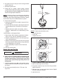
Figure 4.7 Ratio Regulator Adjustment
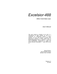
NOTE: To adjust manual butterfly valve:
a. Loosen set screw
b. Turn dial
c. Tighten set screw
Outer Dial
c. Measure low fire gas pressure to the burner gas inlet
[. Verify pressure at [ is within the range specified
on the datasheet for your burner.
Full Open
d. Verify repeatability of ignition and low fire flame
signal.
11. Close all pressure taps.
Step 4: Set Low Fire Gas
Set Screw
en
WARNING
75%
Op
Ŷ This procedure is written with the assumption the
burner has a flame monitoring control system
installed and operating. A proper purge cycle must
be part of the system and purge timing should not
be bypassed.
1. Verify bias adjusting screw X on ratio regulator spring
column is three full clockwise turns (360° x 3) up from
the bottom.
2. Set manual gas butterfly valve to 75% open. See
Figure 4.8.
Figure 4.8 Manual Butterfly Valve Adjustment
3. Open all manual gas shut off valves.
4. Set system control to stay at low fire during and after
ignition sequence.
5. With taps open, connect manometer between Tap B
and the combustion chamber.
6. Ignite the burner.
14
Eclipse Winnox Burner, WX Series, V2, Installation Guide 111, 2/26/2010
7. Turn bias adjusting screw X slightly to achieve
0.1" w.c. (0.3 mbar) 'p between Tap B and the
combustion chamber. Repeat ignition sequence until
burner lights.
NOTE: If viewing the flame, it should be blue with flashes
of yellow. The flame should be completely within the
combustion tube. When firing propane or butane, a proper
low fire flame may have sustained flashes of yellow.
7. Measure gas pressure at the burner inlet Y and verify
the pressure is within the range specified on the
datasheet.
8. If required gas flow cannot be achieved, refer to
Chapter 5, “Maintenance & Troubleshooting” in this
manual.
Step 6: Verify Settings
8. Verify low fire flame.
a. Drive control motor from low fire and back. Verify
low fire and stable flame signal are repeated.
b. Turn the burner off and repeat the ignition
sequence. Verify low fire and stable flame signal are
repeated.
Tap C
9. Close all pressure taps.
Chamber
Step 5: Set High Fire Gas
Figure 4.10 Verify Pressure Settings
1. With burner lit, drive control motor to high fire.
2. Wait for the chamber to reach normal operating
conditions (e.g. chamber temperature, process flows,
etc.).
Tap B
To
Chamber
Tap C
3. Measure high fire fuel using fuel flow measurement
device. Compare this to the rated high fire on
datasheet.
4. Measure high fire air differential pressure between
Tap C and the chamber. Compare this pressure to the
“Air 'p vs. Input” chart on the datasheet.
Figure 4.9 High Fire Gas Adjustment
1. Set manual gas butterfly valve to 75% open. See
Figure 4.8.
NOTE: To adjust manual butterfly valve:
a. Loosen set screw
b. Turn dial
c. Tighten set screw
2. With burner lit, drive control motor to high fire position.
3. Measure air loading line pressure from Tap C to the
chamber.
4. Refer to the “Air 'p vs. Input” graph on appropriate
datasheet and determine the desired input for
measured air 'p.
5. Measure gas flow and input using customer supplied
measuring device.
6. Adjust high fire gas flow using manual butterfly valve
X (refer to step 1 for adjustment procedure) to match
the desired input determined in step 4.
Eclipse Winnox Burner, WX Series, V2, Installation Guide 111, 2/26/2010
5. Drive the control motor to low fire and verify low fire
flame signal and flame appearance (if viewing).
6. Cycle burner from high to low several times to check
repeatability of settings.
7. Readjust burner if the settings do not repeat as
expected. If necessary, refer to Chapter 5,
“Maintenance & Troubleshooting”.
8. Use the system setup summary sheet on page 21 to
record all setup data as an aid for future
troubleshooting and setup operations.
CAUTION
Ŷ Do not turn the combustion air blower off until the
chamber temperature is below 250°F (121°C). This
will prevent hot gases from back flowing into the
burner and blower causing damage to the burner.
9. Stop the burner.
15
Maintenance &
Troubleshooting
This section is divided into two parts. The first part
describes the maintenance procedures, and the second
part helps you to identify problems that may occur and
gives recommendations on how to solve these problems.
Preventative maintenance is the key to a reliable, safe
and efficient system. The following are suggested
guidelines for periodic maintenance. Burners in severe
environments or operational conditions should be
checked more frequently.
NOTE: The monthly and yearly lists are an average
interval. If your environment is dirty, then the intervals may
be shorter. Check with local authorities having jurisdiction
on their recommended maintenance schedules.
5
Yearly Checklist
1. Test (leak test) safety shut-off valves for tightness of
closure.
2. Test pressure switch settings by checking switch
movements against pressure settings and compare
these with the actual impulse pressure.
3. Visually check ignition cable and connectors.
4. Inspect impulse piping for leaks.
5. Be sure the following components are not damaged or
distorted:
• the burner nozzle
• the igniter
• the flame sensors
CAUTION
• the combustion tube or block
Ŷ Turn off the power to the burner and controls
before proceeding with burner inspection.
Monthly Checklist
1. Inspect flame-sensing devices for good condition and
cleanliness.
2. Check for proper air/gas pressures. Refer to the
Winnox datasheet, series 111.
3. Test all alarms for proper signals.
4. Check and clean igniter electrodes.
5. Check the air control valve for smooth, trouble free
operation and adjustment.
6. Check for
equipment.
the
proper
operation
of
ventilating
7. Test interlock sequence of all safety equipment and
manually make each interlock fail, noting that related
equipment closes or stops as specified by the
manufacturer. Test flame safeguard by manually
shutting off gas to burner.
8. Test all manual fuel valves for operation.
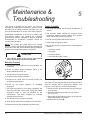
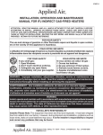
Figure 5.1 Component Inspection
The nozzle can be inspected without removing the burner
from the chamber wall or entering the chamber. See
Figure 5.1 and Figure 5.2. Perform the following:
a. Shut the burner off and manually close the main gas
shut off cocks.
b. Allow the chamber temperature to cool down to
250°F (121°C).
c. Disconnect the gas piping at a union or the gas inlet
flange X provided on the burner.
d. Remove the four bolts Y.
9. Clean and/or replace the combustion air blower filter.
10.Inspect and clean the combustion air blower rotor.
16
Eclipse Winnox Burner, WX Series, V2, Installation Guide 111, 2/26/2010
CAUTION
Ŷ Do not attempt to remove the rear cover by
removing the inner circle bolts \. Internal burner
parts will be damaged.
e. Remove bolts ].
f. Remove the rear cover / nozzle assembly Z from the
burner housing [.
g. To reassemble, follow this sequence in the reverse
order.
NOTE: The combustor can be inspected only by removing
the burner from the chamber wall or entering the chamber.
Figure 5.2 Nozzle Inspection
Recommended Spare Parts
To make sure that the downtime of the system is as short
as possible in case of a failure, you should keep a stock of
spare parts. Please refer to the Eclipse Product
Information Center (EPIC) for a full listing of spare parts:
http://www.eclipsenet.com/products
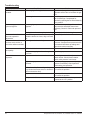
Troubleshooting
Problem
Start-up sequence runs but
burner does not light.
Possible Cause
Solution
No ignition. There is no power to the ignition Restore the power to the ignition
transformer.
transformer.
No ignition. Open circuit between the
ignition transformer and the igniter.
Repair or replace the wiring to the igniter.
No ignition. The igniter needs cleaning.
Clean the igniter.
No ignition. The igniter is not correctly
grounded to the burner.
Clean the threads on the igniter and the
burner. NOTE: Do not apply grease to the
threads on the igniter.
No ignition. Igniter insulator is broken.
Igniter is grounding out.
Inspect the igniter. Replace if broken.
Igniter grounds out, igniter is bent.
Inspect ignitor by removing nozzle and rear
cover. Check if gaps exist, readjust if
needed.
Not enough gas. The gas pressure into the Check the start-up setting. Measure the
ratio regulator is too low.
gas pressures and adjust where necessary.
Not enough gas. The impulse line to the
ratio regulator is leaking.
Repair any leaks.
Not enough gas. The adjustable orifice
valve is not open far enough.
Adjust bypass or low fire gas.
Not enough gas. Start gas solenoid valve
does not open.
Check the solenoid valve coil for proper
operation. Replace it if necessary.
Not enough gas. Gas valve does not open. Check the wiring to the automatic gas shutoff valve. Check the output from the flame
safeguard. Open manual gas cock.
Not enough gas. Ratio regulator is
incorrectly set.
Adjust the ratio regulator to the proper
setting.
No flame signal. Broken flamerod and/or
dirty UV scanner lens.
Inspect and clean sensor. Replace if
necessary.
Too much gas. Gas butterfly valve too far
open.
Check for proper setting.
Eclipse Winnox Burner, WX Series, V2, Installation Guide 111, 2/26/2010
17
Troubleshooting
Problem
Possible Cause
The low fire flame is weak or Not enough gas flowing to the burner.
unstable.
Not enough air.
Solution
Adjust the ratio regulator or bypass fuel
adjustable orifice valve to increase the gas
flow.
Check for proper blow rotation. Check air
filter for blockage. Compensate for
chamber by opening the low fire air butterfly
valve position.
The burner goes out when it Not enough gas pressure into the ratio
cycles to high fire.
regulator.
Check the start-up settings. Measure the
gas pressures and adjust them where
necessary. Check for valve train pressure
loss.
Loading line to the ratio regulator is leaking. Repair the leak in the loading line.
The burner is erratic and
does not respond to
adjustment.
Internal damage to the burner. Some parts Contact Eclipse for further information.
inside the burner are loose, dirty or burned
out.
The burner is unstable or
The air/gas ratio is out of adjustment.
produces soot, smoke, or
excessive carbon monoxide.
Measure all the gas pressures and air
pressures. Compare these pressures to the
documented initial start-up settings and
adjust them where necessary.
The burner cannot achieve
full capacity.
Air filter is blocked.
Clean or replace the air filter.
Cannot initiate a start
sequence.
Air pressure switch has not made contact. Check air pressure switch adjustment.
Check air filter. Check blower rotation.
Check outlet pressure from blower.
Gas pressure going into the ratio regulator Adjust the gas pressure.
is too low.
High or low gas pressure switch has
activated.
Check incoming gas pressure. Adjust gas
pressure if necessary. Check pressure
switch setting and operation.
Malfunction of the flame safeguard system Have a qualified electrician troubleshoot
(e.g. shorted-out flame sensor or electrical and correct the problem.
noise in the sensor line).
18
No power to the control unit.
Have a qualified electrician troubleshoot
and correct the problem.
Main power is off.
Be sure the main power to the system is
switched to the “On” position.
Eclipse Winnox Burner, WX Series, V2, Installation Guide 111, 2/26/2010
Appendix
Conversion Factors
Metric to English
From
To
Multiply By
cubic meter (m³)
cubic foot (ft³)
35.31
cubic meter/hr (m³/h)
cubic foot/hr (cfh)
35.31
degrees Celsius (°C)
degrees Fahrenheit (°F)
(°C x 9/5) + 32
kilogram (kg)
pound (lb)
2.205
kilowatt (kW)
BTU/hr
3414
meter (m)
foot (ft)
3.28
millibar (mbar)
inches water column ("w.c.)
0.401
millibar (mbar)
pounds/sq in (psi)
14.5 x 10-³
millimeter (mm)
inch (in)
3.94 x 10⁻²
MJ/Nm³
BTU/ft³ (standard)
2.491 x 10⁻²
From
To
Multiply By
kiloPascals (kPa)
millibar (mbar)
10
meter (m)
millimeter (mm)
1000
millibar (mbar)
kiloPascals (kPa)
0.1
millimeter (mm)
meter (m)
0.001
From
To
Multiply By
BTU/hr
kilowatt (kW)
0.293 x 10-³
cubic foot (ft³)
cubic meter (m³)
2.832 x 10⁻²
cubic foot/hour (cfh)
cubic meter/hour (m³/h)
2.832 x 10⁻²
degrees Fahrenheit (°F)
degrees Celsius (°C)
(°F - 32) ÷ 5/9
foot (ft)
meter (m)
0.3048
inch (in)
millimeter (mm)
25.4
inches water column ("w.c.)
millibar (mbar)
2.49
pound (lb)
kilogram (kg)
0.454
pounds/sq in (psi)
millibar (mbar)
68.95
BTU/ft³ (standard)
MJ/Nm³
40.14
Metric to Metric
English to Metric
Eclipse Winnox Burner, WX Series, V2, Installation Guide 111, 2/26/2010
19
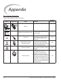
Appendix
Key to System Schematics
These are the symbols used in the schematics.
Symbol
Appearance
Name
Remarks
Bulletin/
Info Guide
Winnox
Main gas
shut-off
valve train
Main Gas Shut-Off Valve Train
Gas Cock
`
NC
Solenoid Shut-Off Valve
(Normally Closed)
Pressure Regulator
Ratio Regulator
20
Eclipse strongly endorses NFPA
as a minimum.
Gas cocks are used to manually
shut-off the gas supply on both
sides of the main gas shut-off
valve train.
Solenoid valves are used to
automatically shut off the gas
supply on a bypass gas system or
on small capacity burners.
756
710
760
The pressure regulator reduces
gas pressure to a stable, usable
pressure.
684
A ratio regulator is used to control
the air/gas ratio. The ratio
regulator is a sealed unit that
adjusts the gas flow in ratio with
the air flow. To do this, it measures
the air pressure with a pressure
sensing line, the impulse line. This
impulse line is connected between
the top of the ratio regulator and
the burner body.
743
Eclipse Winnox Burner, WX Series, V2, Installation Guide 111, 2/26/2010
Appendix
System Setup Summary
Burner Settings
Parameters
Main gas pressure
Low Fire
High Fire
Gas pressure into the ratio regulator
Bypass fuel differential pressure:
Tap E - Chamber
High fire input: Fuel Flow
Measurement Device
Loading line pressure:
Tap C - Chamber
Flame Signal Strength
Tap C
Tap E
Fuel Flow
Measurement
Device
Tap Locations
Eclipse Winnox Burner, WX Series, V2, Installation Guide 111, 2/26/2010
21
Offered By:
Power Equipment Company
2011 Williamsburg Road
Richmond, Virginia 23231
Phone (804) 236-3800
Fax (804) 236-3882
www.peconet.com