1
_Convertible
®
Caution:
Read and follow
al_ Safety Rules
and Instructions
Before Operating
This Equ=pment
oAssembly
oOperatien
oCustemer Respensibinities
o ServRceand Adjustment
o Repair Parts
Sears, Roebuck and Co., Chicago, _L 60684 U.S.A.
......
ll,li,Nil,ll
SAFETY
Practices RULES
for Ride-On
Safe Operation
Mowers
IMPORTANT: THIS CUTTING MACHINE tS CAPABLE OF AMPUTATING HANDS AND FEET AN D THROWING OBJECTS,
FAILURE TO OBSERVE THE FOLLOWING SAFETY INSTRUCTIONS COULD RESULT IN SERIOUS INJURY OR DEATH.
to
GENERAL
•
Read, understand, and follow all instructions in the manual
and on the machine befol'e starting
Onty allow responsible adults, who are familiar with the
instructions, to operate the machine.
Clear the area of objects such as rocks, toys, wire, etc.,
which could be picked up and thrown by the bladeo
Be sure the area is clear ofother people before mowing. Stop
machine if anyone enters the area_
•
,
•
•
•
•
•
•
•
•
•
•
•
•
It.
OPERATION
iii. CHILDREN
Tragic accidents can occur if the operator is not alert to the
presence of children. Children ate often attracted to the machine
and the mowing activity_ Never assume that children will remain
where you last saw them.
*
"
.
Before and when backing, look behind and down for small
children
.
Never carrY children. They may fall off and be seriously
injured or interfere with safe machine operation.
.
.
Never allow children to operate the machine,
Use extra care when approaching blind corners, shrubs,
trees, or other objects that may obscure vision
IV.
SERVICE
Never carry passengers.
Do not mow in rover se unless absolutely necessary. Always
look down and behind before and while backing..
Be aware of the mower discharge direction and do not point
it at anyone. Do not operate the mower without either the
entire grass catcher or the gua_'d in place_
Slow down before turning,
Never leave a running machine unattended. Always turn off
blades, set parking brake, stop engine, and remove keys
before dismounting.
Turn off blades when not mowing.
Stop engine before removing grass catcher or unclogging
chute.
Use extra care in handling gasoline and other fuels, They are
flammable and vapors are explosive..
Use only an approved container
Never remove gas cap or add fuel with the engine
running Allow engine to cool before refueling. Do not
smoke.
Mow only in daylight or good artificial light.
Do not operate the machine while under the influence of
alcohol or drugs.
Watch for traffic when operating near or crossing roadways.
Use extra care when loading or unloading the machine into
a trailer or truck.
SLOPE
Never refuel the machine indoors.
Never store the machine or fuel container inside where
there is an open flame, such as a water heater_
Never run a machine inside a closed area_
Keep nuts and boits, especially blade attachment bolts, tight
and keep equipment in good condition,
OPERATION
Never tamper with safety devices.
operation regularly_
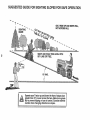
Slopes are a major factor related to loss-of,-control and tipover
accidents, which can result in severe injury or death° All slopes
require extra caution. If you cannot back up the slope or if you feel
uneasy on it, do not mow it.
Mow up and down slopes, not across.
Remove obstacles such as rocks, tree limbs, etc.
•
Watch for holes, ruts, or bumps.
Uneven terrain could
overturn the machine_ Tall grass can hide obstacles.
Use slow speed. Choose a low gear so that you will not have
to'stop or' shift while or] the slope.
Follow the nlanufacturer's
recommendations
for wheel
weights or counterweights to improve stability.
Use extra care with grass catchers or other attachments,
These can change the stability of the rnachine.
•
•
•
•
•
Stop and inspect the equipment if you stri!<e an object.
Repair, if necessary, before restarting
Never make adjustments or repairs with the engine running,
i
o
Keep all movement on the slopes slowand gradual Do not
make sudden changes in speed or direction..
Avoid starting or stopping on a slope. If tires lose traction,
disengage the blades and proceed slowly straight down the
slope,
•
•
Do not turn on slopes unless necessary, and then, turn slowly
and gradually downhill, if possible.
Do not mow near drop-offs, ditches, or embankments° The
mower could suddenly turn over if a wheel is over the edge
of a cliff or ditch, or if an edge caves in.
Do not mow on wet grass. Reduced traction could cause
sliding.
°
Do not try to stabilize the machine by putting your foot on the
ground.
•
Do not use grass catcher on steep slopes.
Grass catcher components are subject to wear, damage, and
deterioration, which could expose moving parts or allow
objects to be thrown. Frequently check components and
replace with manufacturer's recommended parts, when nec.
essary.
Mower blades are sharp and can cut, Wrap the blade(s) or
wear gloves, and use extra caution when servicing them.
Check brake operation frequently
Adjust and service as
required_
Look for this symbol to point out Important safety precautions.
It means
CAUTION!!! BECOME ALERT![I YOUR
SAFETY IS INVOLVED.
DO NOT:
•
Check their proper
Keep machine free of grass leaves or other debris build-up.
Clean oil or fuel spillage_ Allow machine to cool before
storing.
DO:
•
•
Keep children out of the mowing area and under the watchful
care of another responsible adulL
Be alert and turn machine off if children enter the area.
CAUTION:
Always disconnect
spark
plug wire and place wire where tt cannot
contact spark plug in order to prevent
accidental
starting
when setttng up,
transporting,
adjusting
or making
repairs.
2
PRODUCT
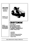
CONGRATULATIONS
on your purchase of a Sears
tractor. It has been designed, engineered and manufactured to give you the best possible dependability and
performance.
Should you experience any problem you cannot easily
remedy, please contact your nearest Sears Service
Center/Department..
We have competent, well-trained
technicians and the proper tools to service or repair this
unit,
Please read and retain this manual° The instructions will
enable you to assemble and maintain your unit properly,,
Always observe the "SAFETY RULES",
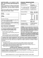
MODEL
NUMBER
917.255692
SPECgFICATIONS
HORSEPOWER:
l&0
GASOLINE CAPACITY:
3,5 GALLONS
UNLEADED REGULAR
OIL (3.0 PINTS w/o FILTER)
(35 PINTS w/FILTER)
SAE 30 (Above 32°F)
5W-30 (Below 32°F)
SPARK PLUG (GAP030 IN):
CHAMPION RC12YC
VALVE CLEARANCE:
INTAKE;
.0015-°0030IN_
EXHAUST: .0020-..0035IN.
GROUND SPEED:
FORWCARD:
1st
1o10
2rid
1.40
3rd
2.00
4th
3°00
5th
4.20
6th
&00
REVERSE: 1.50
SERIAL
NUMBER
DATE OF PU RCHASE
THE MODELAND SERIAL NUMBERS WILL BE FOUND
ON A PLATE UNDER THE SEAT.
YOU SHOULD RECORD BOTH SERIAL NUMBERAND
DATE OF PURCHASE AND KEEP lN A SAFE PLACE
FOR FUTURE REFERENCE.
TIRE PRESSURE:
FRONT: 14 PSI
REAR: 10 PSt
CHARGING
15 AMPS @ 3600 RPM
SYSTEM;
BLADE BOLT TORQUE:
MAINTENANCE
30-35 FT. LBSo
AGREEMENT
WARNING: This unit is equipped with an internal combustion engine and should not be used on or near any unimproved forest-covered, brush-covered or grass-covered
land unless the engine's exhaust system is equipped with
a spark arrester meeting applicable local or state laws (if
any), if a spark arrester is used, it should be maintained in
effective working order by the operator°
A Sears maintenance agreement is available on this product, Contact your nearest Sears store for details.
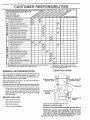
CUSTOMER
MPH
MPH
MPH
MPH
MPH
MPH
MPH
RESPONSIBILITIES
,
Read and observe the safety rules°
•
Follow a regular schedule in maintaining, caring for and
using your unit.
•
Follow the instructions under "Customer Responsibilities" and "Storage" sections of this owner's manual.
LIMITED TWO YEAR WARRANTY
in the state of California the above is required by law
(_Section 4442 of the California Public Resources Code).
Other states may have similar laws. Federal laws apply on
federal lands. A spark arrester for the muffler is available
throughyour nearest Sears authorized service center (See
the "REPAIR PARTS" section of this manual).
ON ELECTRIC
START RiDiNG
EQUIPMENT
For two (2) years from the date of purchase,ff this dding equipment is maintained, lubricated and tuned up according to the
instructionsin the owner's manual, Sears wil! repair or replace, free of charge, any parts found to be defective in material or
workmanship.
This Warranty does not cover:
•
Expendable items which become worn during normal use, such as blades, spark plugs, air cleaners and belts.
*
Tire replacement or repair caused by punctures from outside objects, such as nails, thorns, stumps, or glass.
,
Repairs necessary because of operator abuse, negligence, improper storage or accident or the failure to maini.aintile
equipment according to the instructions contained in the owner's manual.
,
Riding equipment used for commercial or rental purposes.
LIMITED 90 DAY WARRANTY
ON BATTERY
For 90 days from date of purchase, if any battery includedwith this riding equipment proves defective in material or workmanship
and our testing determines the battery willnot hold a charge, Sears weltreplace the battery at no charge°
WARRANTY SERVICE IS AVAILABLE BY RETURNING THE RIDING EQUIPMENT TO THE NEAREST SEARS SERVICE
CENTER/DEPARTMENT IN THE UNITED STATES
This Warranty gives you specific legal rights, and you may also have other rights which may vary from state to state,
SEARS, ROEBUCK AND COo, Di731CR-W, SEARS TOWER, CHICAGO, ILLINOIS 60684
3
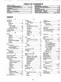
TABLE OF CONTENTS
SAFETY RULES ............................................................
2
PRODUCT SPECIFICATIONS ....................................... 3
CUSTOMER RESPONSIBILITIES ..................... 3, 15-18
WARRANTY ...................................................................
3
TABLE OF CONTENTS .................................................
4
INDEX .............................................................................
4
TRACTOR ACCESSORIES ........................................... 5
ASSEMBLY ..............................................................
7-10
OPERATION ...........................................................
t1-14
MAINTENANCE SCH EDULE ...................................... 15
SERVICE AND ADJUSTMENTS ............................ 19-23
STORAGE ....................................................................
24
TROUBLESHOOTING ............................................
25-26
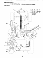
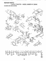
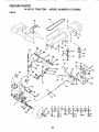
REPAIR PARTS - TRACTOR ................................. 28-43
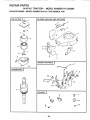
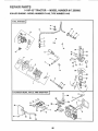
REPAIR PARTS - ENGINE ..................................... 44-49
PARTS ORDERING/SERVICE ................... BACK PAGE
iNDEX
A
Accessories ............................................. 5
Adjustments:
Brake ................................................. 2t
Carburetor ....................................... 23
Mower
Front-To-Back ........................ 20
Side-To .Side ............................ 20
Throttle Control Cable .................. 23
Air Filter, Engine ................................... t7
Air Screen, Engine .............................. 17
Assembly ........................................... 7-i 0
B
Battery:
Charging ........................................... 8
Cleaning .......................................... 16
Installation ...................................... 9
Levels ................................... 8,16-t7
Preparation .................................... 8
Starting with Weak Battery .......... 22
Storage ........................................
24
Terminals .................................... 16
Belt:
Motion Drive
Removal/Replacement
........... 21
Mower Blade Ddve
Removal/Rep!acemen
t ........... 21
Blade:
Sharpening ..................................
Replacement .... ...........................
Brake Adjustment ...............................
t6
16
21
C
Carburetor Adjustment ............ •.......... 23
Controls, Tractor .................................. ! 1
Customer Responsibilities ............. 15-18
Engine:
Air Filter ..................................... 17
Air Filter Foam Pre-Cleaner .... 17
Air Screen, Engine .................. 17
Battery ...................................... 16
Engine Oil ................................ 17
Fuel Filter ................................ t8
Oil Filter ...................................... 18
Spark Plugs .............................. 18
Tractor:
Blade ............................................ 16
Lubrication Chart ...................... 15
Maintenance Schedule .............. 15
Tire Care ......................... 8,t6,22
Cutting Height, Mower ........................ 12
E
Electrical:
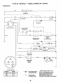
Schematic ..................................... 27
Wiring Diagram ............................... 28
Engine:
Air Filter .......................................... 17
Air Filter Foam Pre-Cleaner ........ 17
Air Screen ..................................... 17
Oil Change .................................. 1?
Oil Level ......................................13,17
Oil Type .............................................17
Preparation .................................... 13
Repair Parts ................................44-49
Starting ............................................ 14
Storage .......................................... 24
F
Filter:
Air Filter .........................................
Air Filter Foam Pre-Cleaner ........
Fuel ..................................................
Oil
Fuel:
.....................................................
17
17
18
18
Type ............................................... 13
Storage .................................................
24
Fuse ...........................................................22
L
Leveling Mower Deck .......................... 20
Lubrication:
Chart ............................................ 15
M
Maintenance Schedule ......................... 15
Mower:
Adjustment, Front-to-Back ............ 20
Adjustment, Side4o-Side ............. 20
Blade Sharpening ......................... 16
Blade Replacement ...................... 16
Cutting Height ............................... t2
Installation ................................... 19
Operation ....................................... 13
Removal ...................................... ,....19
Mowing Tips ......................................... t4
Muffler .................................................. 18
Spark Arrester ............................. 3,36
Mulcher Plate ........................................ 10
O
Oil:
Cold Weather Conditions ....... 13,17
Engine .........................................
17
Filter .............................................. 18
Storage ........................................
24
4
Operation ......................................
11-14
Operating Mower .... ;...............................13
Options:
Accessories .................................... 5
Spark Arrester .......................... 3,36
P
Parking Brake .................................. 11-12
Parts Bag ..............................................
6
Parts, Replacement/Repair
........... 28-43
Product Specifications ........................... 3
R
Repair Parts ...................................... 28-43
S
Safety Rules ............................................ 2
Seat ......................................................... 8
Service and Adjustments ............... 19-23
Carburetor .........................................23
Fuse ............................................. 22
Motion Drive Belt
Removal/Replacement
............ 21
Mower Blade Drive Belt
Removal/Replacement
............ 21
Mower Adjustment
Front- to-Back ......................... 20
Side-to-Side .................... ;.........20
Mower Removal .......................... 19
Tire Care ..................................8,! 6,22
Slope Guide Sheet ............................... 51
Spark Plugs ......................................... 18
Specifications ....................................... 3
Starting the Engine .......................... 13-14
Steering Wheel ................................. 7,22
Stopl3ing the Tractor ........................... t 2
Storage ................................................
24
T
Throttle Control Cable
Adjustment .................................... 23
Tires ......................................................
8,16,22
Trouble Shooting Chart ................... 25-26
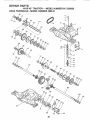
Transaxle:
Repair Parts ............................ 42-43
W
Warranty ................................................... 3
Wiring Diagram ..................................... 28
Wiring Schematic ............................... 27
ACCESSORmES AN
...........
i
A ACH
,,
....................................
i,ll,,ll
.....
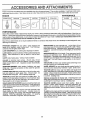
These accessories and attachments were available when the unit was purchased, They are also available at most Sears retail outlets,
catalog and service centers, Most Sears stores can order these items for you when you provide the model number of your tractor
ENGINE
SPARK PLUG
MAINTENANCE
MUFFLER
AIR FILTER
GAS CAN
ENGINE OIL
STABILIZER
BLADES
BELTS
PERFORMANCE
Sears offers a wide variety of attachments that fit your vehicle. Many of these are listed below with brief explanations of how they can
helpyou This list was current at the time of publication; however, it may change in futureyears- more attachments may be added, changes
may be made in these attachments, or some may no longer be available or fit your model Contact your nearest Sears store for the
accessories
and attachments that are available for your unit,
Most of these attachments
attaching and detaching.
do not require additional hitches or conversion kits (those that do are indicated) and are designed for easy
SNOW BLADE for snow removal only. 14-1nchhigh, 42-inch
wide blade clears 38-inch path when angled left or right, Raises,
lowers with side lever_ Adjustable skids; replaceable, reversible
scraper bar. (Use with t_rechains, wheel weights, or rear drawbar
weight,)
PERMANEX BAGGER lets you collect
grass clippings and
leaves for a healthier, nearer looking lawn
Two Permanex
containers hold 30-gallon plastic bags.
LAWN SWEEPERS
let you collect grass clippings and leaves,
LAWN VACS for powerful collection of heavy grass clippings and
leaves. Wand attachment to pick up debris in hard-to-reach
places,
CARTS make hauling easy
SNOWTHROWER has40-inch swath. Drum-type auger handles
powdery and wet/heavy snow. Mounts easily with simple pin
arrangement. Discharge chute adjusts from tractor seat, 6-inch
diameter spout discharges snow 10 to 50 feet, Lift controlled at
tractor seat (Use with chains, wheel weights, or rear drawb_
weight.)
TIRE CHAINS are heavy duty; closely spaced extra-large cross
links give smooth ride, outstanding traction.
WHEEL WEIGHTS for rear wheels provide needed traction for
snow removal or dozing heavy materials In pairs. (30 ibs each )
Variety of sizes available,
ROLLER for smoother tawn surface.
36-inch wide, 18-inch
diameterwater4ight drum holds upto3901bs ofweight, Rounded
edges prevent harm to turf,, Adjustable scraper automatically
cleans drum
SPREADERiSEEDERS
make seeding, fertilizing, and weed
killing easy
Broadcast spreaders are also useful for granular
de-icers and sand
TRACTOR CAB has heavy duty vinyf fabric over tubular steel
frame, ABS ptas_ctop; clear plastic windshield offers 360 degree
visibility. Hinged metal doors with catch. Keeps operator warm
and dry, Remove vinyl and windshields for use as sun protector
in summer° (Catalog only.)
CORING AERATOR takes small plugs out of soil to allow moisture and nutrients to reach grass roots. 364nch swath. 24
hardened steel coring tips. 150 Ib. capacity weight tray.
AERATOR promotes deep root growth for a healthy lawn Tar
pered 25-inch steel spikes mounted on 10-inch diameter discs
puncture holes in soil at close intervals to let moisture soak in.
Steel weight tray for increased penetration
Optional accessories for tractor cab: tinted/temperedsolid
safetyglass windshieldwith hand operatedwiper;12wolt amber
cautionlightfor mountingon cab top. (Catalogonly.)
TRACTOR COVER protects tractor from weather. Made of
Evolution3 fabric (water-rape!lent,extremely breathable, light
weight, soft, non-abrasive,pliable in all temperatures,durable,
stain/tear/puncture resistant,willnotshrinkor stretch.) (Catalog
only.)
TILLER has5 hp engine and36-inchswathto prepareseed beds,
cultivate,and compostgarden residue. Tiller hasitsown built-in
lift and depth controlsystemand doesNOT requirea sleevehitch
Fits any lawn, yard, or garden tractor. Simply hook up to the
tractordrawbar and go!
MULCH RAKE/DETHATCHER
loosens soil and flips thatch and
matted leaves to lawn surface for easy pickup. Twenty spring fine
teeth, Useful to prepare bare areas forseeding. Availableforfront
or rear mounting_
SPRAYERS use 12-volt DC electric motor that connects to the
tractor battery or other 12-volt source,
includes booms for
automatic spraying when pulling, and hand held wand for spot
spraying,
Wand has adjustable spray pattern. For applying
herbicides, insecticides, fungicides, and liquid fertilizers,.
5
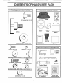
CONTE
TS OF HARDWA
Parts Bag contents shown full size
E PACK
Parts packed separately
in carton
0
Seat
i
-------.
Battery acid
(1) Shoulder Bolt 5/16-18
1
Steerlng
Wheel
( ) Knob
Mulcher
Plate
Battery
Steering
Sleeve
i1 ) Washer 17/32 x 1-3/16 x 12 Ga.
Ownerls Manual
@
(2) Screw #10 x 5/8
Parts bag contents not shown full size
(2) Washer, Lock #t0
4
(2) Washer 3/16 x 3/4 x 16 Ga,
i
Parts Bag
i
G
(2) Latch Hook
Assembly
(2) Nut, Weld #10
@
(2) Hex Bolts 1/4 - 20 x 3/4
Wheel
Steering
Insert
I_
_tilll/
_\_!_!\\!!!!_!_!_!_!_!_i\_
(2) Battery Cardage Bolts 1/4-20 x 7-1/2
(2) Hex Nuts 1/4.20
(2) Keys
'Terminal Guard
(2) Washers 9/32 x 5/8 x 16 Ga,(2) Lock Washers 1/4
il
(2) Wing Nuts !/4- 20
,,,,,,,,,,,,,,,,,,,
,.....
15° Slope Sheet
:_
6
!
Battery Caps
and Instructions
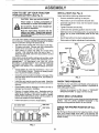
ASS
LY
Your new tractor has been assemb ed at the factory with exception of those parts left unassembled for shipping purposes
To ensure safe and proper operation of your tractor all parts and hardware you assemble must be tightened securely. Use
the correct tools as necessary to insure their proper tightness.
TOOLS
REQUIRED
FOR ASSEMBLY
......STEERING
WHEEL
INSERT
A socket wrench set will make assembly easier_ Standard
wrench sizes are listedo
(2) 7/16" wrenches
(1) Tire pressure gauge
(1) Screwdriver
(1)
3/4" socket w/drive ratchet
(1) I/2" wrench
(1)
Utility knife
STEERING
WHEEL
When right and left hand is mentioned in this manual, it
means when you are in the operating position (seated
behind the steering wheel).
TO REMOVE
UNPACK
•
•
•
UNIT FROM CARTON
CARTON
Remove all accessible loose parts and parts cartons
from carton (See page 6).
Cut along lines on the carton, from top to bottom, all
four corners of carton and lay panels flaL
Check for any additional loose parts or cartons and
remove.
BEFORE
ATTACH
ROLLING
STEERING
UNIT OFF SKID
WHEEL
(See Fig. 1)
•
Remove hex Iocknut and large flat washer from steering shaft°
•
Position front wheels of the tractor so they are pointing
straight forward.
•
Position steering sleeve over steering shaft.
,
Position steering wheel so cross bars are horizontal
(left to right) andslide onto adapter.
,
Secure steering wheel to steering shaft with hex locknut and large fiat washer previously removed. Tighten
securely.
,
Snap insert into center of steering wheel°
•
Remove protective plastic from tractor hood and grill,
IMPORTANT: CHECK FOR AND REMOVEANY STAPLES
IN SKID THAT MAY PUNCTURE TIRES WHERE UNIT IS
TO ROLL OFF SKID.
FIG. 1
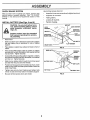
CLUTCHfBRAKE
PEDAL
MFT LEVER
(See Fig. 2)
•
•
°
•
•
Raise attachment lift lever to its highest position.
Release parking brake by depressing clutch/brake
pedal,
Place gearshift lever in "NEUTRAL" position,
Roll unit backwards off skid.
Remove banding holding discharge guard up against
tractor.
/
FIG. 2
7
LY
HOW TO SET UP YOUR TRACTOR
PREPARE BATTERY (See Fig. 3)
CAUTION:
if
Do not smoke. Fumes from charged bataccldentalty
contact with batter=/acid.
tery
acid are tn
explosive.
Read the Instructions Included with the
battery vent caps. Always wear gloves,
clothing and goggles to protect your hands,
skin and eyes.
Your unit has a battery charging system which is sufficient
for normal use° However, periodic charging of the battery
with an automotive charger will extend its life,
°
•
•
SEAT (See Fig. 4)
Adjust seat before tightening adjustment knob,
Wear eye and face shield.
Wash hands or clothing immediately
_
INSTALL
•
Remove cardboard packing on seat pan.
•
Place seat on pan and assemble shoulder bolt.
•
Assemble adjustment
Do not tighten,
.
Tighten shoulder bolt securely.
°
Lower seat into operating position and sit on seat°
•
Slide seat until a comfortable position is reached which
allows you to press clutch/brake pedal all the way
down.
.
Get off seat without moving its adjusted position.
•
Raise seat and tighten adjustment knob securely.
knob and flat washer loosely.
SEAT
See instructions packed with vent caps in parts bag
Fill battery with acid. Fill each cell until it reaches the
bottom of the vent wells, Do not overfill,
Allow battery to stand and settle for at least thirty
minutes° After standing, check the level of acid_ If
below the vent wells, add more acid until the correct
level is reached.
SEAT PAN
SHOULDER
BOLT
While battery is standing (after adding acid) and later, while
battery is being charged, continue with assembly of unit.
IMPORTANT:
TO MAXIMIZE THE LIFE OF YOUR
BATTERY, IT IS NECESSARY THAT THE BATTERY BE
CHARGED BEFORE USE
FAILURE TO CHARGE
BATTERY CAN RESULT IN A SHORTENED BATTERY
LIFE,
•
•
•
Charge battery at a rate of 6 amperes for 1 hour° Use
a 12 volt battery charger, Observe all safety precautions required for battery charging_
ADJUSTMENT
KNOB
Check the acid level after the battery is charged. If the
acid has fallen below the correct level, add distilled or
iron free water.
FIG. 4
Instaltthe vent caps to cover the vent wells° Wash the
top of the battery with water to remove any acid, then
wrpe dry.
.
Check battery case for leakage to make sure that no
damage has occurred in handling.
•
Dispose of excess battery acid. Neutralize acid for
disposal by _dding it to four inches of water in a five
gallon plastic container, Stir with a wooden or plastic
paddle while adding baking soda until the addition of
more soda causes no more foaming.
°
FLAT WASHER
CHECK
TIRE PRESSURE
The tires on your unit were overinflated at the factory for
shipping purposes_ Correct tire pressure is important for
best cutting performanceo
•
Reduce tire pressure to PSI shown in "PRODUCT
SPECIFICATIONS
on page 3 of this manual_
CHECK DECK LEVELNESS
For best cutting results, mower housing should be properly
leveled. See "TO LEVEL MOWER HOUSING" in the
Service and Adjustments section of this manual
Follow instructions on how to install battery_
VENT CAP
CUT AWAY VIEW
CHECK FOR PROPER POSiTiON OF ALL
BELTS
VENT WELL
See the figures that are shown for replacing motion, mower
drive, and mower blade drive belts in the Service and
Adjustments section of this manual. Verify that the belts are
routed correctty_
BATTERY
CELL ACID
LEVEL
FIG. 3
8
CHECK
BRAKE
Use terminal access doors for:
SYSTEM
After you learn how to operate your tractor, check to see
that the brake is properly adjusted.. See "TO ADJUST
BRAKE" in the Service and Adjustments section of this
manual,
INSTALL
BATTERY
(See Figs. 5 and 6)
,
Inspection for secure con nections (to tighten hardware).
,
Inspection for corrosion_
,
Testing battery.
•
Jumping (if required).
°
Periodic charging.
CAUTION: Do not short battery terminals. Before Installing battery, remove
rings, etco
metal bracelets, wristwatch bands,
Postttve terminal must be connected
first to prevent sparking from accidental grounding.
HE)(
(NEGATIVE)
FLAT
_WASHER
".
BLACK CABLE
Raise hood_
,
•
Place battery in plastic tray, battery terminals to front of
tractor,
,
First connect RED battery cable to positive (+) battery
terminal with hex bolt, flat washer, lock washer and hex
nut as shown. Tighten securely.
,
Connect BLACK grounding cable to negative (-) battery
terminalwith remaining hex bolt, flat washer, lock washer
and hex nut. Tighten secureiyo
•
Slide the two battery bolts through the terminal guard
and start the wing nuts onto the threads.
•
Position terminal guard over the battery as shown, lower
bolts into keyholes and slide square shafts of bolts into
slots of key holes°
•
Tighten wing nuts by hand making sure battery bolts
remain in slots of the key holes in the battery support°
Be sure terminal access doors are closed..
•
BOLTS
Make sure drain tube is fastened to drain hole in battery
tray and battery tray is positioned in hole of battery
support.
FLAT WASHER
DRAIN TUBE
FIG, 5
WINGNUTS,
TERMINAL
GUARD
TERMINAL
DOORS
BATTERY BOLT
:!
CAPS
KEY HOLE
BATTERY TRAY
FIG. 6
9
ASS
BLY
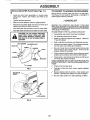
INSTALL MULCHER PLATE (See Figs. 7 &
TO CONVERT TO BAGGING OR DISCHARGING
•
Install two latch hook assemblies to mulcher plate
using screw, washer', lock washer, and weld nut as
shown.
Simply remove mulcher plate and store in a safe place.
Your mower is now ready for discharging or installation of
optional grass catcher accessory'.
•
Tighten hardware securely,
•
Raise and hold deflector shield in upright position.
°
•
Place front of mulcher plate over front of mower deck
opening and slide into place, as shown_
Hook front latch into tab hole on front of mower deck.
°
Hook rear latch into tab hole on back of mower deck.
e)
,/'CHECKLIST
BEFORE YOU OPERATE AND ENJOY YOUR NEW
TRACTOR, WE WISH TO ASSURE THAT YOU RECEIVE
THE BEST PERFORMANCE AND SA TISFA CTION FROM
THIS QUALITY PRODUCT
PLEASE REVIEW THE FOLLOWING
CAUTION: Do not remove discharge
guard from mower. Raise and hold
guard when attaching mulcher plate
and allow it to rest on plate while in
operation.
LOCKWASHER
MULCHER
,!
SCREW
No remaining loose parts in carton.
PLATE
WASHER
All assembly instructions have been completed.
,/
Battery is properly prepared and charged.
1 hour at 6 amps)
,/
Seat is adjusted comfortably and tightened securely.
J'
Al! tires are properly inflated. (For shipping purposes,
the tires were over-inflated at the factory),
,I
Be sure mower deck is properly leveled side-to-side/
front-to-rear for best cutting results_ (Tires must be
properly inflated for leveling),
v"
Check mower and drive belts. Be sure they are routed
properly around pulleys and inside all belt keepers,
WELD NUT
\_
CHECKLIST:
LATCH
LATCH
(Minimum
,/"
LOCK
WASHER
Check wiring See that all connections are still secure
and wires are properly clamped,
WHILE LEARNING HOW TO USE YOUR TRACTOR, PAY
EXTRA ATTENTION TO THE FOLLOWING IMPORTANT
ITEMS:
WELD NUT
FIG. 7
J
Engine oil is at proper level.
J
Fuel tank is filted with fresh, clean, regular unleaded
gasoline.
Become familiar with alt controls - their location and
function. Operate them before you start the engine.
4'
DEFLECTOR
SHIELD
,/
LATCH
HOOKS
FIG. 8
10
Be sure brake system is in safe operating condition.
OPERATION
KNOW YOUR TRACTOR
READ THiS OWNER'S
MANUAL
AND SAFETY
RULES
BEFORE
OPERATING
YOUR TRACTOR.
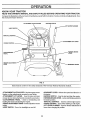
Compare the illustrations with your tractor to familiarize yourself with the location of various controls and adjustments. Save
this manual for future reference.,
ATTACHMENTCLUTCHLEVER
IGNITION SWITCH
LEVER PLUNGER
UGHT SWITCH
THROTTLE CONTROL
LIFT lPVER
CLUTCH/BRAKE
PEDAL
It
J
HEIGHT ADJUSTMENT
KNOB
PARKING BRAKE
LEVER
GEARSHIFT LEVER
FIG. 9
Sears tractors conform to the safety standards of the American National Standards Institute.
ATTACHMENT CLUTCH LEVER - Used to engage mower
blades or other attachments mounted to your tractor,,
ATTACHMENT LIFT LEVER - Used to raise and lower
GEARSHIFT LEVER - Selects the speed and direction of
the tractor°
IGNITION SWITCH - Used to start and stop the engine_
PARKING BRAKE LEVER - Locks clutch/brake pedal into
the brake position°
THROTTLE CONTROL - Used to control engine speed°
CHOKE CONTROL - Used when starting a cold engine_
LIFT LEVER PLUNGER- Used to release attachment lift
mower deck or other attachments mounted to your tractor,
CLUTCHIBRAKE
PEDAL - Used for declutching and
braking the tractor and starting the engine,
HEIGHT ADJUSTMENT KNOB., Used to adjust the mower
height°
LIGHT SWITCH - Turns the headlights on and off.
lever when changing its position,
11
OPERATIO
The operatlon of any tractor can result in foreign objects thrown into the eyes, which can result
In severe eye damage. Always wear safety glasses or eye shields before starting your tractor
and whlle movlng. We recommend Wide Vision Safety Mask for over the spectacles or standard
safety glasses.
HOW TO USE YOUR TRACTOR
TO MOVE FORWARD
TO SET PARKING
(See Fig. 10)
°
BRAKE
(See Fig. 10)
Depress clutch/brake pedal into full "BRAKE" position
and hold.
The direction and speed of movement is controlled by the
gearshift lever.
Place parking brake lever in "ENGAGED" position and
release pressure from clutch!brake pedal, Pedal should
remain in "BRAKE" position, Make sure parking brake
will hold vehicle secure.
•
Start tractor with clutch/brake pedal depressed and
gearshift lever in "NEUTRAL" position_
•
Move gearshift
STOPPING
(See Fig. 10)
Move attachment clutch lever to "DISENGAGED"
sition.
poAT'r'ACHMENT
CLUTCH LEVER
GROUND DRIVE•
Depress clutch/brake pedal intofull "BRAKE" position.
POSITION
"ENGAGED"
TH ROTTLE
CONTROL
,
Move gearshift fever to "NEUTRAL" position.
ENGINE ,
"DISENGAGED"
POSITION
PARKING BRAKE
"ENGAGED"
POSITION
_
GEARSHIFT
LEVER
Move throttle control to "SLOW" position.
CHOKE
CONTROL
NOTE; Failure to move throttle control to "SLOW" position
and allowing engine to idle before stopping may cause
engine to "backfire".
.
Turn ignition key to "OFF" position and remove key.
Always remove key when leaving vehicle to prevent
unauthorized use.
•
Never use choke to stop engine.
"DISENGAGED"
POSITION
NOTE; Under certa!n conditions when unit is standing idle
with the engine running, hot engine exhaust gasses may
cause "browning" of grass, To eliminate this possibility,
always stop engine when stopping unit on grass areas.
"BRAKE"
POSITION
TO USE CHOKE
CONTROL
TO ADJUST
(See Fig. 10)
Always operate engine at full throttle.
Operating engine at less than full throttle reduces the
battery charging rate.
•
Full throttle offers the best bagging mower performanGe,
POSITION
MOWER
CUTTING
HEIGHT
.
Turn knob clockwise to raise cutting height.
,
Turn knob counterclockwise
to lower cutting heighL
The cutting height range is approximately 1-1/4" to 3-3/4"_
The heights are measured from the ground to the blade tip
with tile engine not running. These heights are approximate and may vary depending upon soil conditions, height
of grass and types of grass being mowed.
To engage choke control, pull knob out, Slowly push
knob in to disengage,
,
PEDAL "DRIVE"
Tile cutting height is controlled by turning the height adjustment knob in desired direction.
(See Fig. 10)
CONTROL
CLUTCH/BRAKE
(See Fig. 10)
Use choke control whenever you are starting a cold engine.
Do not use to start a warm engine.
TO USE THROTTLE
HEIGHTADJUSTMENT
KNOB
FIG. 10
as described above, before leaving the
operator's
position;stoptounitcompletely,
empty grass
CAUTION: Always
catcher, etc,
•
lever to desired position,
•
Slowly release clutch/brake pedal to start movement.
IMPORTANT; BRING TRACTOR TO A COMPLETE STOP
BEFORE SHIFTING OR CHANGING GEARS, FAILURE
TO DO SO WILL SHORTEN THE USEFUL LIFE OF YOUR
TRANSAXLE.
MOWER BLADES •
AND BACKWARD
12
o
The average lawn should be cut to approximately
2-1/2 inches during the cool season and to over 3
inches during hot months. For healthier and better
looking lawns, mow often and after moderate growth.
.
For best cutting performance, grass over 6 inches in
height should be mowed twice, Make the first cut
relatively high; the second to desired height,
TO OPERATE
MOWER
BEFORE STARTaNG THE ENGINE
(See Fig. 9)
Your unit is equipped with an operator presence sensing
switch. Any attempt by the operator to leave the seat with
the engine running and the mower clutch engaged will shut
off the engine°
CHECK
°
The engine in your unit has been shipped, from the
factory, already filled with summer weight oil.
o
Select desired height of cut, using height adjustment
knob.
°
Check engine oil with unit on level ground°
o
o
Lower mower with lift lever..
°
Engage mower by slowly moving mower clutch lever to
"ENGAGED" position..
TO STOP MOWER - Move mower clutch lever to
"DISENGAGED" position.
Unthread and remove the oil fill cap/dipstick; wipe oil
off., Reinsert the dipstick into the tube and rest the oil
fill cap on the tube. Do not thread the cap onto the tube.
Remove and read oil level.. If necessary, add oil until
"FULL" mark on dipstick is reached.. Do not overfill.
°
For cold weather operation you should change oil for
easier starting (see "OIL VISCOSITY CHART" in the
Customer Responsibilities section of this manual).
°
To change engine oil, see the Customer Responsibilities section in this manual
•
CAUT,oN:
A J_
I
P=k
without either the entire grass catcher,
on mowers Do
so not
equipped,
disoperate or
thethe
mower
charge guard in place.
ENGINE
OIL LEVEL
ADD GASOLINE
°
Fill fuel tank. Use fresh, clean, regular unleaded
gasoline.. (Use of leaded gasoline will increase carbon
and lead oxide deposits and reduce valve life)..
IMPORTANT: WHEN OPERATING IN TEMPERATURES
BELOW 32°F(0°C), USE FRESH, CLEAN WINTER GRADE
GASOLINE TO HELP INSURE GOOD COLD WEATHER
STARTING,
TO OPERATE ON HILLS
CAUTION:
Do not drive up or down
hills with slopes greater than 15 ° and
do not drive across any slope.
•
Choose the slowest speed before starting up or down
hills.
°
Avoid stopping or changing speed on hills°
•
If slowing is necessary, move throttle control lever to
slower position.
•
If stopping is absolutely necessary, push clutch/brake
pedal quickly to brake position and engage parking
brake.
°
Move gearshift
°
To restart movement, move gearshift lever to 1st gear°
Be sure you have allowed room for unit to roll slightly as
you restart movement°
°
Slowly release parking brake and clutch/brake pedal.
o
Make all rums slowly.
WARNING:
Experience indicates that alcohol blended
fuels (called gasohol or using ethanol or methanol) can
attract moisture which leads to separation and formation of
acids during storage. Acidic gas can damage the fuel
system of an engine while in storage° To avoid engine
problems, the fuel system should be emptied before storage of 30 days or longer. Drain the gas tank, start the
engine and let it run until the fuel lines and carburetor are
empty. Use fresh fuel next season.. See Storage Instructions for additional information.
Never use engine or
carburetor cleaner products in the fuel tank or permanent
damage may occur_
lever to "NEUTRAL" position..
filler neck. Do not overfill. Wipe offany
CAUTION:
bottom
of gas
tank
spilled
oil orFill
fuel.to Do
not store,
spill
or
use gasoline near an open flame.
TO TRANSPORT
°
Raise attachment lift control to highest position,
°
When pushing or towing your unit, be sure gearshift
lever is in "NEUTRAL" position.
°
Do not push unit at more than five (5) MPH.
13
...............
!ill ,i , i
i! ii,
:
OPERATION
Hi ,_Ulll
..........
TO START
ENGINE
(See Fig.
::: .....
.
10)
When starting engine for the first time or if engine has
run out of fuel, it wilt take extra cranking time to move
fuel from the tank to the engine.
•
Depress the clutch/brake pedal and set the parking
brake_
°
o
Place gearshift lever in "NEUTRAL" position.,
Move attachment clutch to "DISENGAGED" position,
•
Pull choke control out to "CHOKE" position for cold
engine start_ For warm engine start do not use
choke control.
•
Move throttle control to midway between "FAST" and
"SLOW" positions.,
o Turn ignition key clockwise to "START" position and
release key as soon as engine starts. Do not run
starter continuously for more than fifteen seconds
per minute, if engine does not start after several
attempts, move throttle control to "FAST" position,
wait a few minutes and try again.
°
When engine starts, slowly push choke control in..
°
Move throttle control to "FAST" position.
-
Allow engine to warm up for a few minutes before
engaging clutch/brake pedal or attachment clutch
lever.
•
.
Always operate engine at full throttle when mowing
to assure better mowing performance and proper discharge of material
Regulate ground speed by selecting a low enough gear to give the mower cutting
performance as well as the quality of cut desired.
o
When operating attachments, select a ground speed
that will suit the terrain and give best performance of
the attachment being used°
MULCHING MOWING TIPS
°
Tire chains cannot be used when the mower housing is attached to unit.
Mower should be properly leveled for best mowin_
performance. See 'q'O LEVEL MOWER HOUSING'
tn the Service and Adjustments
section of this
manual,
.
The left hand side of mower should be used for trimruing.
.
Drive so that clippings are discharged ot'_to the area
that has beon cut. Have the cut area to the right of
the machine. This will result in a more even distribution of clippings and more uniform cutting..
-
o
TIPS
=
If grass is extremely tall, it should be mowed twice
to reduce load and possible fire hazard from dried
clippings. Make first cut relatively high; the second
to the desired height ......
Do not mow grass when it is wet. Wet grass will
plug mower and leave undesirable clumps, Allow
grass to dry before mowing
IMPORTANT:
FOR BEST PERFORMANCE,
KEEP
MOWER HOUSING FREE OF BUILT-UP GRASS AND
TRASH_ CLEAN AFTER EACH USE,.
• The special mulching blade will recur the grass clippings many times and reduce them in size so that as
they fall onto the lawn they will disperse into the grass
and not be noticed. Also, the mulched grass will
biodegrade quickly to provide nutrients for the lawn..
Always mulch with your highest engine (blade) speed
as this will provide the best recutting action of the
blades.
NOTE: If at a high altitude (above 3000 feet) or' in cold
temperatures (below 32 ° F), the carburetor fuel mixture
may need to be adjusted for best engine performance.
See 'q'O ADJUST CARBURETOR" in the Service and
Adjustments section of this manual
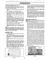
MOWING
.......
°
°
o
When mowing large areas, start by turning to the
right so that clippings will discharge away from
shrubs, fences, driveways, etc. After one or two
rounds, mow in the opposite direction making left
hand turns until finished(See
Fig° 11).
Avoid cutting your' lawn when it is wet. Wet grass
tends to form clumps and interferes with the mulching
action. The best time to mow your lawn is the early
afternoon_ At this time the grass has dried and the
newly cut area will not be exposed to the direct sun.
For' best results, adjust the mower cutting height so
that the mower cuts off only the top one-third of the
grass blades (See Fig,. 12).. For extremely heavy
mulching, reduce your' width of cut and mow slowly.
Certain types of grass and grass conditions may
require that an area be mulched a second time to
completely hide the clippings. When doing a second
cut, mow across or perpendicular to the first cut path.
Changeyourcuttingpatternfromweektoweek,
Mow
north to south one week then change to east to west
the next week. This will help prevent matting and
graining of the lawn_
MAX 1/3
f
,t,
FIG. 12
FIG. 11
14
.....
MAINTENANCE
ESPONSm M
E
CUSTO
SCHEDULE
ES
,,.--___
.,,- _.,..,._.,,_ ,._e,,._,__
AS YOU COMPLETE
Check Brake Operation
.......
_
6/'
.
:
;
............... _
_
!
_
........
Check Tire Pressure
T
Check for Loose Fasteners
R
A
SharpeniRepiaceMower
C
check Battery LeveiiRecharge
0
Clean Battery andTerrnlnals
R
CheckTransmtssion
6#4
v",
Blades
Lubrication Chart .............
q
e,"............
.....
Cooling
Adjust Blade Belt(s) Tension
Adjust Motion Drive Belt(s) Tension
Check Engine Oil Level
6#4'
Change Engine Oil
$f
$##'
6_I,2,3
Clean Air Filter
6442
"cJean
AirScreen
.......................
G
I
N
=
Inspect MuffleriSparkArrester
Replace O11Filter (if equipped) .................................
.
Engine Cooling Fins
.
, 6_,2_
......................
6#42
,..,.ReplaceSpark Plug ................................
..........
,...................
,6#4
Replace Air Filter Paper Cartridge ........................
6##'
, ........ 6#42
Replace Fuel Filter
6#4
3 ,. If equipped with oil filter, change otl every 50 hours
4 - Replace blades more often when mowing tn sandy soil
5 - If equipped with _.d_ustable system
1 - Change mo_e o_en when operating under a heavy load or in high ambient temperatures
2 - Service mere often when operating in dtrty o!' dusty cendl_lons
GENERAL
LUBRICATION
RECOMMENDATIONS
CHART
The warranty on this vehicle does not cover items that have
been subjected to operator abuse or negligence,
To
receive full value from the warranty, operator must maintain unit as instructed in this manual.
(_) FRC
BEARING
Some adjustments will need to be made periodically to
properly maintain your unit.
" FRONT WHEEL _)
BEARING ZERK
ZERK
All adjustments in the Service and Adjustments section of
this manual should be checked at least once each season.
@
Once a year you should replace the spark plug, clean
or replace air filter, and check blades and belts for
wear. A new spark plug and clean air filter assure
proper air-fuel mixture and help your engine run better
andlast longer,
BEFORE
EACH
CLUTCH
PIVOT(S)
USE
PIVOTS
•
Check
•
Check
brake operation°
•
Check
tire pressure,
(_$AE
for loose fasteners,
(_) GENERAL PURPOSE GREASE
•
Check
engine
®
oil level,
30 OR 10W30 MOTOR OIL API - SG
@ REFER TO CUSTOMER
15
RESPONSIBILITIES
"ENGINE"
SECTION
IMPORTANT:
DO NOT OIL OR GREASE THE PIVOT POINTS
WHICH HAVE SPECIAL NYLON BEARINGS,
VISCOUS LUBRICANTS WILL ATTRACT
DUST AND DIRT THAT WILL SHORTEN
THE LIFE OF THE SELF-LUBRICATING
BEARINGS.
IF YOU
FEEL THEY MUST BE LUBRICATED,
USE ONLY A DRY, POWDERED GRAPHITE
TYPE LUBRICANT
SPARINGLY,
CUSTO
ESPONSI
TRACTOR
LUTm
Always observe safety rules when performing any maintenance.
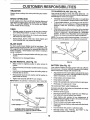
TO SHARPEN
BLADE
(See Fig. 14)
Care should be taken to keep the blade balanced. An
unbalanced blade will cause excessive vibration and eventual damage to mower' and engine.
.....
BRAKE OPERATION
.
The blade can be sharpened with a file or o na grinding
wheel.. Do not attempt to sharpen while on the mower.
.
To check blade balance, you will need a 5/8" diameter
steel bolt, pin, ora cone balancer_ (When using a cone
balancer, follow the instructions supplied w_th bal-
if unit requires more than six (6) feet stoppingdistance at
high speed in highest gear, than brake mustbe adjusted
(See "TO ADJUST BRAKE' in the Service and Adjustments section of this manual).
arlcer)_
o
TIRES
•
Maintainproper airpressure in all tires (See "PRODUCT SPECIFICATIONS
on page 3 of this manual).
o
Keep tires free of gasoline, oil, or insect control chemicals which can harm rubber.
°
Avoid stumps, stones, deep ruts, sharp objects and
other hazards that may cause tire damage_
Slidebladeon toan unthreadedportion
ofthesteelbolt
orpinand holdtheboltorpinparallel
withtheground.
If blade is balanced, it should remain in a horizontal
position. If either end of the blade moves downward,
sharpen the heavy end until the blade is balanced.
NOTE: Do not use a nail for balancing blade. The lobes of
the center hole may appear' to be centered, but are noL
CENTER HOLE
BLADE CARE
For best results mower blades must be kept sharp. Tile
blades can be sharpened with a file or on agdnding wheel.
We suggest they be sharpened or replaced after every 25
hours of mowing. Check blades more often if mowing in
sandy conditions°
•
Do not attempt to sharpen blades while they are on the
mower.
°
Replace bent or damaged blades°
FIG. 14
BLADE REMOVAL (See Fig. 13)
•
BLADE
5!8" BOLT
OR PIN
Raise mower to highest position to allow access to
blades°
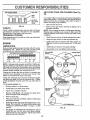
BATTERY (See Fig. 15)
o
Remove hex bolt, lock washerand flat washersecuring
blade_
•
Install new or resharpened blade with trailing edge up
towards deck as shown,
Your unit has a battery charging system which is sufficient
for normal use. However, periodic charging of the battery
with an automotive charger will extend it's life.
-
Reassemble hex bolt, lock washer and flat washer in
exact order as shown°
°
Tighten bolt securely (30-35 Fto Lbs. torque),
IMPORTANT: BLADE BOLT,IS GRADE 8 HEATTREATED.
_,i_
BLADE
Acid solution level in each battery cell should be even
with bottoms ofvent wells_ Add only distilled or ironfree
water if necessary. Do not overfill
•
•
Keep battery and terminals clean°
Keep battery bolts tight.
•
Keep vent caps tight and small vent holes in caps open.
•
Recharge at 6 amperes for 1 hour..
TO CLEAN BATTERY AND TERMINALS ,.
MANDREL
ASSEMBLY
FLATWAS.ER.
°
T.AlU.GEDaE
/
LOCK WASHER __
_"_
HEX BOLT (GRADE 8)*
*AGRADE 8HEATTREATEDBOLTCAN BE
IDENTIFIED BY SIX LINES ON THE BOLT HEAD,
FIG. 13
16
Corrosion and dirt on the battery and terminals can cause
the battery to "leak" power.
•
Remove terminal guard°
°
Disconnect BLACK battery cable first, then RED battery cable and remove battery from tractor.
°
Wash battery with solution of four tablespoons of
baking soda to one gallon of water., Be careful not to get
the soda solution into the cells,
°
=
Rinse the battery with plain water' and dry.
Clean terminals and battery cable ends with wire brush
until brighL
°
°
Coat terminals with grease or petroleum jelly.
Reinstall battery (See "INSTALL BATTERY"
Assembly section of this manual).
in the
CUSTOME
CUT AWAY VIEW
_
_
RESPO
AiR FILTER
16)
VENTCAP
VENT
WELL
FIG. 15
o
V-BELTS
Check V-belts for deterioration and wear after 100 hours
and replace if neces-sary_ The belts are not adjustable.
Replace belts ifthey begin to slip from wear°
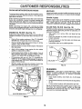
PRE-CLEANER
(See Fig.
Remove foam pre-cleaner
the paper cartridge.
element by sliding it off of
NOTE: Do not attempt to clean or oil the paper cartridge.
Replace paper cartridge once a year or after every 100
hours of operation; more often if used in very dusty or dirty
conditions_
COOLING
Keep transaxle free from build-up of dirt and chaff which
can restrict cooling°
ENGINE
LUBRICATION
Only use high quality detergent o!1rated with API service
classification SG,, Select the oil s SAE viscosity grade
according to your expected operating temperature°
RECOMMENDED
FOAM
Your engine wilI not run properly and may be damaged by
using a dirty air filter. Clean the foam preocleaner element
after every 25 hours of operation, more often if tractor is
used in very dusty, dirty conditions,
°
Remove knob and cover.
CELL ACID
LEVEL
TRANSAXLE
TreES
°
Wash foam pre-cleaner in liquid detergent and water.
=
Wrap foam pre-cleaner in cloth and squeeze dry.
•
Lightly coat foam pre-cleaner with clean engine oil
Squeeze in towel to remove excess oil. Do not saturate°
°
Install foam pre-cleaner over paper cartridge.
•
Reassemble cover and tighten knob securely_
AIR CLEANER
COVER
SAE VISCOSITY GRADES
KNOB
• WING NUT
FOAM
PRE.CLEANER
°F -20 °
°C -29 °
0a
-18 °
32 °
0°
60 °
16°
80°
27°
-\
100 °
38°
NOTE: Although multi-viscosity oils (5W30, i0W30 etc.)
improve starting in cold weather, these multi-viscosity oils
wilt result in increased oil consumption when used above
32°F, Check your engine oil level more frequently to avoid
possible engine damage from running low on oil,,
Change the oil after the first two hours of operation and
every 50 hours thereafter or at least once a year if the
tractor is not used for 50 hours in one year°
Check the crankcase oil level before starting the engine
and after each eight (5) hours of continuous use. Tighten
oil fill cap!dipstick securely each time you check the oil
level.
TO CHANGE ENGINE OiL o
Be sure vehicle is on level surface
°
o
Oil will drain more freely when warm.
Catch oil in a suitable container°
o
Remove oil fill dipstick, Be careful not to allow dirt to
enter the engine when changing oil
•
Remove drain plug_
°
After oil has drained completely, replace oil drain plug
and tighten securely.
•
Refill engine with oil through oil fill dipstick tube. Pour
slowly. Do not overfill. For approximate capacity see
"PRODUCT SPECIFICATIONS"
on page 3 of this
manual.
°
AIR CLEANER
PAPER CARTRIDGE
CLEANER
BASE
OIL
RLLER CAP
AND DIPSTICK
AIR INTAKE
SCREEN
OILDRAINPLUG
FIG. 16
Use gauge on oil fill dipstick for checking level, Do not
thread the cap onto the tube when taking reading°
Keepoit at"FULL" line on dipstick, Tighten cap onto the
tube securely when finished
17
CUSTO
CLEAN
AiR INTAKE/COOLiNG
ESPONSN
AREAS
LITnE$
MUFFLER
Inspect and replace corroded muffler and spark arrester (if
equipped) as it could create a fire hazard and/or damage.
To insure proper cooling, make sure the air intake screen,
cooling fins, and other external surfaces of the engine are
kept clean at all times..
SPARK
PLUGS
Every 100 hours of operation (more often under extremely
dusty, dirty conditions), remove the blower housing and
other coohng shrouds_ Clean the cooling fins and external
surfaces as necessary., Make surethe cooling shrouds are
reinstalled.,
Replace spark plugs at the beginning of each mowing
season or after every 100 hours of use, whichever comes
first., Spark plug type and gap setting are shown in
"PRODUCT SP ECIFICAT1ONS" on page 3 of this manual
NOTE: Operating the engine with a blocked air' intake
screen, dirty or plugged cooling fins, and/or cooling shrouds
removed, will cause engine damage due to overheating°
IN-LINE
(See Fig. 18)
Fuelfilter should be replaced once each season° Iffuelfilter
becomes clogged, obstructing fuel flow to carburetor, replacement is required.
•
With engine cool, remove filter' and plug fuel line
sections.
ENGINE OIL FILTER (See Fig, 17)
Replace the engine oil filter' every season or' every other oil
change if the tractor' is used more than 100 hours in one
yea_'.
•
Place new fuel filter in position in fuel line with arrow
toward carburetor.
Be sure there are no fuel line leaks and clamps are
properly positioned.
Immediately wipe up any spilled gasoline.
o
Drain oil from engine crankcase ( See "TO CHANGE
ENGINE OIL" through step remove drain plug)o
°
°
Remove oil filter drain plug located at base of oil filter'
adapter_ Allow oil filter to drain.
°
°
Remove oil filter and wipe off filter' adapter_ Reinstall oil
filter drain plug.
•
Apply a thin coating of new engine oil to the rubber
gasket on replacement oil filter°
o
Insta{I replacement oil filter' on fitter' adapter. Turn oil
filter clockwise until rubber gasket contacts the filter
adapter, then tighten filter an additional 1/2 turn.
°
Fill crankcase with new oil ( See "TO CHANGE ENGINE OIL' in this section of this manual). For approximate capacity see"PRODUCT SPECIFICATIONS" on
page 3 of this manual..
°
FUEL FILTER
CLAMP_
__j
CLAMP
FUEL FILTER
Start the engine and check for oil leaks. Correct any
leaks before placing engine into full operation.
FIG. 18
OIL FILTER
CLEANING
IMPORTANT:
FOR BEST PERFORMANCE,
KEEP
MOWER HOUSING FREE OF BUILD-UP, GRASS AND
TRASH_ CLEAN UNDERSIDE OF MOWER HOUSING
AFTER EACH USE°
O
•
Clean engine, battery, seat, finish, etc. of all foreign
matter.
°
Keep finished surfaces and wheels free of all gasoline,
oil, etc_
°
Protect painted surfaces with automotive type wax°
We do not recommend using a garden hose to clean your
unit unless the electrical system, muffler, air filter and
carburetor are covered to keep water out. Water in engine
can result in a shortened engine life_
OIL RLTER DRAIN PLUG
FIG. 17
18
SERVmCEAN
cALiTION:
ADJUSTMENTS
BEFORE PERFORMING ANY SERVICE OR ADJUSTMENTS:
Depress clutch/brake pedal fully and set parking brake,
e
t
Place gearshift lever in "NEUTRAL" position.
Place attachment clutch in "DISENGAGED"
position.
w
Turn tgnltlon key "OFF" and remove key.
Make sure the blades and all movlng parts have completely stopped.
m
Disconnect spark plug wire from spark plug and place wire where tt cannot come in contact with
plug.
TRACTOR
SEE NOTE ABOVE
CONNECT
TO REMOVE MOWER (See Fig. 17)
POSTION
Mower will be easier to remove from the right side of unit.
•
Place attachment clutch in "DISENGAGED" position.
°
Move attachment lift lever forward to lower mower to its
lowest position,
•
Roll belt off engine pulley,
•
Disconnect clutch rod from clutch lever by removing
retainer spring,
•
Disconnect suspension arms from rear deck brackets
by removing retainer springs.
°
Disconnect front links from deck by removing retainer
springs,
•
Raise lift lever to raise suspension arms., Slide mower
out from under tractor,
IMPORTANT:
IF AN ATTACHMENT OTHER THAN THE
MOWER IS TO BE MOUNTED TO THE TRACTOR, BOTH
SUSPENSION
ARMS MUST BE REMOVED FROM
TRACTOR.
TO INSTALL
MOWER
TRUNNION
)_TRUNNION
10-11/32"
Z
CLUTCH
"_'-'
CLUTCH LEVER
PARALLEL
RETAINER
SPRING
(See Fig. 17)
•
•
Raise attachment fift lever to its highest position.
Slide mower under tractor with discharge guard to right
side of tractor,
°
Lower lift lever to its lowest position,
•
install mower in reverse order of removal instructions,
NOTE: The mower clutch rod has a trunnion that has been
preset, atthe factory, for optimum mower performance, DO
NOT MOVETHETRUNNION
ON THE CLUTCH ROD° If for
any reason the trunnion has been moved on the clutch rod,
it must be reset to correct position (parallel with clutch rod)
and measure 10-11/32" (Check dimension on edge of fiat
work surface as shown)°
Be sure to tighten trunnion nut securely against trunnion
after making any adjustments°
ENGINE
PULLEY
SUSPENSION
ARMS
RETAINER
SPRINGS
SIDES)
RETAINER
SPRINGS
(BOTH SIDES)
FIG. 19
19
......................
SERVICE A
TO LEVEL MOWER
i
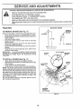
FRONT-TO-BACK ADJUSTMENT (See Fig& 22 and 23)IMPORTANT: DECK MUST BE LEVEL S_DE-TO-SIDE. IF
THE FOLLOWING FRONT*TO-BACK ADJUSTMENT IS
NECESSARY, RE SURE TO ADJUST BOTH FRONT LINKS
EQUALLY SO MOWER WtLL STAY LEVEL SIDE-TOSIDE
Adjust the mower while tractor is parked on level ground or
driveway.
Make sure tires are properly inflated (See
"PRODUCT SPECIFICATIONS" on page 3). if tires are
over or under inflated, you wilt not properly adjust your'
mower.
To obtain the best cutting results, the mower housing
should be adjusted so that the front is approximately 1/4" to
3/4" lower than the rear when the mower is in its highest
position,
Check adjustment on right side of tractor Measure distance "D" directly in front and behind the mandrel at bottom
edge of mower housing as shown,
SIDE-TO-SIDE ADJUSTMENT (See Figs. 20 and 21) You will need two (2) standard 2 x 4 short pieces of wood
to make the following adjustment, S#nilar blocks measur_
ing 1-1/2" thick may also be used.
•
Raise mower with attachment lift control to allow two
(2) t-1/2" thick blocks to be placed under rear edge of
mower directly behind mandrels,
•
Lower mower deck to its lowest height of cut position
(See "TO ADJUST MOWER CUTTING HEIGHT" in the
Operation section of this manual).
,
On both sides of tractor, loosen, but do not remove, the
fasteners securing the adjustable pivot brackets to
frame, Both brackets must be loose enough to move
freely.
•
Pull down firmly on suspension arm to remove any
slack in pivot bracket and hold while tightening rear
fastener first to secure Tighten remaining fastener.
•
•
Repeat procedure on other side of tractor.
Raise mower with attachment lift control and remove
blocks from under mower_
•
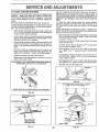
Before making any necessary adjustments, check that
both front _inks are equal in length, Both links should
be approximately 10-3/8"
.
If links are not equal in length, adjust one link to same
length as other link
.
To lower #ont of mower loosen nut "E" on both front
links an equal number of turns
•
When distance "D" is 1/4" to 3/4" lower at front than
rear, tighten nuts "F" against trunnion on both front
links=
•
To raise front of mower, loosen nut "F" from trunnion on
both front links, Tighten nut "E" on both front links an
equal number of turns
•
When distance "D" is 1/4" to 3/4" lower at front than
rear, tighten nut "F" against trunnion on both front links,
•
Recheck side-to-side adjustment.
UNDER REAR EDGE OF
MOWERDECK (Usewood2 x 4'sor equivalent)
MANDREL
FIG. 22
BOTH FRONT UNKS
MUST BE EQUAL
IN LENGTH
MOWER MUST BE IN LOWES:r HEIGHT OF CUT POSITION
FIG. 20
ADJUSTABLEPIVOT
BRACKET
NUT "E"
NUT "F"
PULL DOWN AND
TIGHTEN REAR
FASTENER FIRST'
FRONT LINKS
TRUNNION
.....i
FIG. 21
II n 'll
ADJUSTMENTS
HOUSING
PLACE TWO (2) 1-1/2" THICK BLOCKS
It,l,l,llln,I
2O
FIG. 23
SERVICE AND A JUSTMENT$
TO REPLACE
MOWER
BLADE
DRIVE BELT
WITH PARKING BRAKE "ENGAGED"
(See Fig. 24)
Th°_sm_wr_rt_leadecdrren
bevlttmsa_fabcee"brake,,
For assistance, there is a belt _n_s_i_on_artgrhuk_U_
decal on the mower housing
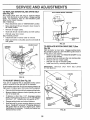
BELT REMOVALo
o
Place attachment clutch in "DISENGAGED" position°
Move attachment lift lever forward to lower mower to
its lowest position.
°
Roll belt off engine pulley°
°
Work belt off both mandrel pulleys and idler pulleys,,
o
Pull belt away from mower..
BELT INSTALLATION o
Install new belt in reverse order of removal.
°
Make sure belt is in all pulley grooves and inside all
belt guides.
FIG. 25
ENGINE PULLEY
MANDREL
PULLEY
TO REPLACE MOTION DRIVE BELT (See
Fig. 26)
IDLER
PULLEYS
ParkFo
r assistance,
the tract°rthere°nleve]is
a _e_tainstEar_lga_igoe
;uai_iengebcr_ken
bottom side of left footrest.
°
Remove mower (See "TO REMOVE MOWER" in this
section of this manual)°
•
Remove belt from stationary idler and clutching idler,,
°
Remove belt from engine pulley_
.
Roll belt over top of transaxle pulley.
°
install new belt by reversing above procedure.
IMPORTANT:
REPLACE
IN THIS MANUAL_
ONLY
MANDREL
PULLEY
WiTH
BELT LISTED
CHASSIS
FIG. 24
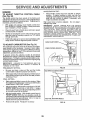
TO ADJUST BRAKE (See Fig. 25)
•
Depress clutcWbrake pedal and engage parking brake.
°
Measure distance between brake operating arm and
nut "A" on brake rod.
CLUTCH|NO
PULLEY
°
Engage parking brake and recheck distance,,
STATIONARY
IDLER
ENGINE
PULLEY
o
thorized service center.
FIG. 26
21
SERVICE AND ADJUSTMENTS
TO ADJUST
STEERING
WHEEL
IMPORTANT:
YOUR UNIT IS EQUIPPED WITH A 12
VOLT NEGATIVE GROUNDED SYSTEM. THE OTHER
VEHICLE MUST ALSO BE A 12 VOLT NEGATIVE
GROUNDED SYSTEM. DO NOT USE YOUR TRACTOR
BATTERY TO START OTHER VEHICLES°
ALIGNMENT
If steering wheel crossbars are not horizontal (left to right)
when wheels are positioned straight forward, remove steering wheel and reassemble per instructionsin theAssembiy
section of this manual.,
TO ATTACH JUMPER CABLES -
FRONT
WHEEL
TOE-II'_CAMBER
Connect each end of the RED cab{e to the POSITIVE
(+) terminal of each battery, taking care not to short
against chassis.
Connect one end of the BLACK cable to the NEGATIVE (-) terminal of fully charged battery.
°
The front wheel toe-in and camber are not adjustable on
your unit° If damage has occurred to affect the front wheel
toe-in or camber, contact your nearest authorized service
center,
•
°
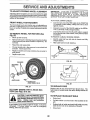
TO REMOVE
WHEEL
FOR REPAIRS
Connect the other end of the BLACK cable to a panel
bolt on the left side of the chassis, away from fueltank
and battery.
(See
Fig. 27)
TO REMOVE CABLES, REVERSE ORDER -
,
Block up axle securely_
•
Remove axle cover, retaining dng and washers to allow
wheel removal (rear wheel contains a square key - Do
not lose).
•
o
o
Repair tire and reassemble.
•
On rear wheels only: align grooves in rear wheel hub
and axle_ insert square key°
=
Replace washers and snap retaining ring securely in
axle groove_
°
Replace axle cover:
BLACK cable first from [eft side of chassis and fully
charged battery.
RED cable last from both batteries.
"POSITIVE ....
NEGATIVE"
(*)
(-)
FIG. 28
WASHERS
RETAINING
RING
PA"EL
L/ J
!
AXLECOVER
_SQUARE
KEY
(REAR WHEEL ONLY)
FIG. 29
TO REPLACE
FIG. 27
Replace with 30 amp automotive-type plug-in fuse. The
fuse holder is located under the dash, directly behind the
engine.
TO START ENGINE WITH A WEAK BATTERY (See Figs. 28 & 29)
CAUTION:
Lead-acid batteries gener-
and smoking materials away from batateexplosive gases. Keep sparks, flame
teries.
Always wear eye protection
when around batteries.
,i,,,
INNIlI'IIL
_
FUSE
I
TO REPLACE
|
|
HEADLIGHT
BULB
•
Raise hood.
•
Pull bulb holder out of the hole in the backside of the
grill.
°
Replace bulb in holder and push bulb holder securely
back into the hole in the backside of the grill
Close hood,
'111'11
If your battery is too weak to start the engine, it should be
recharged. If "jumper cables" are used for' emergency
starting, follow this procedure:
•
22
SERVICE AND ADJUSTMENTS
ACCELERATION
ENGRNE
TO ADJUST
THROTTLE
CONTROL
o
CABLE
(See Fig. 30)
The throttle control has been preset at the factory and
adjustment should not be necessary_ Check adjustment as
described below before loosening cable° If adjustment is
necessary, procede as follows:
o
With ,engineno!, running;, move throttle control lever
from SLOW to CHOKE position. Slowly move lever
from "CHOKE" to "FAST" position,
°
Check to see if hole in throttle lever and hole in speed
control bracket are aligned_
°
If holes are not aligned, loosen cable clamp screw and
align the holes by inserting a pencil or a t/4" drill bit
through both holes°
•
Pull throttle cable up to remove slack and tighten cable
clamp screw. Remove alignment pencil or drill bit..
TEST -
Move throttle control lever from "SLOW" to "FAST"
position,
If engine hesitates or dies, turn idle fuel
adjusting needleout
(counterclockwise)
t/Stum.
Repeat test and continue to adjust, if necessary,
until
engine accelerates
smoothly°
High speed stop is factory adjusted.
Do not adjust damage may resulL
IMPORTANT:
NEVER TAMPER
WiTH
THE ENGINE
GOVERNOR,
WHICH IS FACTORY
SET FOR PROPER
ENGINE SPEED° OVERSPEEDING
THE ENGINE ABOVE
THE
FACTORY
HIGH
SPEED
SETTING
CAN
BE
DANGEROUS.
IF YOU THINK THE ENGINE-GOVERNED
HIGH SPEED NEEDS ADJUSTING,
CONTACT
YOUR
NEAREST
SEARS SERVICE
CENTER,
WHICH
HAS
PROPER EQUIPMENT AND EXPERIENCE
TO MAKE ANY
NECESSARY
ADJUSTMENTS°
CABLE
TO ADJUST
CARBURETOR
(See Fig. 31)
The carburetor has been preset at the factory and adjustment should not be necessary. However, minor adjustment may be required to compensate for differences in fuel,
temperature, altitude or load.. If the carburetor does need
adjustment, proceed as follows:
SPEED
In general, turning the adjusting needles in (clockwise)
decreases the supply of fuel to the engine giving a leaner
fue!/air mixture. Turning the adjusting needles out (counterclockwise) increases the supply of fuel to the engine giving
a-richer fuel/air mixture_
IMPORTANT:
DAMAGE TO THE NEEDLES AND THE
SEATS IN CARBURETOR MAY RESULT tF NEEDLE IS
TURNED iN TOO TIGHT
PRELIMINARY SETTING •
THROTTLE LEVER
FIG. 30
Be sure you have a clean air filter and the throttle
control cable is adjusted properly (see above)°
IDLE SPEED ADJUSTING SCREW
°
With engine offturn idlefuel adjusting needle in (clockwise) closing it finger tight and then turn out (counterclockwise) 1 turn.
FINAL SETTING -
°
°
°
o
Start engine and allow to warm for five minutes. Make
final adjustments with engine running and shift/motion
control lever in "NEUTRAL" position.
ld!e speed setting-With throttle control lever in"SLOW"
position, engine-should idle at 1625 RPM. If engine
idles too slow or fast, turn idle speed adjusting screw in
or out until correct idle is attained_
idle fuel needle setting - With throttle control lever in
"SLOW" position, turn idle fuel adjusting needle in
(,clockwise) until engine begins to die and then turn out
(.counterclockwise) approximately 1/8 to '1/4 turn to
obtain best tow speed performance.
IDLE FUEL ADJUSTING NEEDLE
Recheck idle speed.. Readjust if necessary°
FIG. 31
23
STORAGE
ENGINE
immediately prepare your' tractor for storage at the end of
theseason orifthe unit will not be used for30daysor more.
FUEL SYSTEM
gasoline in the tank inside a building
where fumes may reach an open flame
or
spark. Never
Allow store
the engine
to cool
CAUTION:
the tractor
with
before storing in any enclosure.
_
IMPORTANT:
IT IS IMPORTANT TO PREVENT GUM
DEPOSITS FROM FORMING {N ESSENTIAL
FUEL
SYSTEM PARTS SUCH AS CARBURETOR, FUEL FILTER,
FUEL HOSE, OR TANK DURING STORAGE.
ALSO,
EXPERIENCE INDICATES THAT ALCOHOL BLENDED
FUELS (CALLED GASOHOL OR USING ETHANOL OR
METHANOL) CAN ATTRACT MOISTURE WHICH LEADS
TO SEPARATtON AND FORMATION OF ACIDS DURING
STORAGE.
ACIDIC GAS CAN DAMAGE THE FUEL
SYSTEM OF AN ENGINE WHILE IN STORAGE.
•
Drain the fuel tank.
[
TRACTOR
Remove mower from tractor for winter storage+ When
mower is to be stored for a period of time, clean it thoroughly, remove all dirt, grease, leaves, etc. Store in a
clean, dry area+
•
Start the engine and let it run until the fuel lines and
carburetor are empty.
Never use engine orcarburetor cleaner products inthe
fuel tank or permanent damage may occur,
Use fresh fuel next season,
•
Clean entire tractor (See"CLEANING" in the Customer
Responsibilities section of this manual).
•
=
Inspect and replace belts, if necessary (See belt replacement instructions in the Service and Adjustments
section of this manual).
o
•
Lubricate as shown in the Cu3tomer Responsibilities
section of this manual
*
Be sure that all nuts, bolts and screws are securely
fastened, Inspect moving parts fordamage, breakage
and wear+ Replace if necessary.
NOTE:
Fuel stabilizer is an acceptable alternative in
minimizing the formation of fuel gum deposits during storage+ Add stabilizer to gasoline in fuel tank or storage
container+ Always follow the mix ratio found on stabilizer
container. Run engine at least 10 minutes after adding
stabilizer to allow the stabilizer' to reach the carburetor'. Do
not drain the gas tank and carburetor if using fuel stabilizer.
o
Touch up all rusted or chipped paint surfaces; sand
lightly before painting
ENGINE
OIL
Drain oil (wi!h engine Warm) and replace with clean engine
oil, (See ENGINE" in the Customer' Responsibilities
section of this manual),
BATTERY
,,
Fully charge the battery for storage+
°
After a period of time in storage, battery may require
recharging.
CYLINDERS
°
To help prevent corrosion and power leakage during
long periods of storage, battery cables should be
disconnected and battery cleaned thoroughly (see "TO
CLEAN BATTERY AND TERMINALS" in the Customer Responsibilities section of this manual).
o
Remove spark plug(s),
°
Pour' one ounce of oil through spark plug hole(s) into
cylinder(s)+
•
Turn ignition key to START' position for a few seconds
to distribute oil+
•
After cleaning: leave cables disconnected and place
cables where they cannot come in contact with battery
terminals.
°
Replace with new spark plug(s)+
=
Bi_ sure battery drain tube is securely attached.
t,
OTHER
*
Do not store gasoline from one season to another.
°
Replace your gasoline can if your can starts to rust.
Hust and/or dirt in your gasoline will cause problems.
o
If possible, store your unit indoors and covet it to give
protection from dust and dirt
o
Covet'your unit with a suitable protective cover that
does not retain moisture+ Do not use plastic. Plastic
cannot breathe which allows condensation to form and
wi{Icause your unit to rust.
IMPORTANT: NEVER COVER TRACTOR WHILE ENGINE
AND EXHAUST AREAS ARE STILL WARM.
24
TROU
PROBLEM
Will not start
LESHO0
CAUSE
G PONNTS
CORRECTION
!,
Out of fuel.
1.,
2,
34
4.
5,,
6,
7,
Engine not "CHOKED" properly,
Engine flooded.
Bad spark ptug
Dirty air filter,
Dirty fuel filter.
Water in fuel.
2,
3,
4,
5
6o
7,
8.
9_
10,
Loose or damaged wiring
Carburetoroutof
adjustment,
Engine valves out of adjustmenL
Hard to start
1,
2,
3.
4_
5.
6.
7,
8.
Dirty air filter,
Bad spark plug,
Weak or dead battery,
Dirty fuel lilter.
Stale or dirty fuel,
Loose or damaged wiring,
Carburetor out of adjustment
Engine valves out of adjustment,,
1,
2_
3
4
5.
6,,
7.
8,
Clean/replace air filter.
Replace spark plug,,
Recharge or replacebattery,
Replacefuel filter,
Drain fuel tank and refill with fresh gasoline,,
Check all wiring.
Contact an authonzed service facility°
Contact an authorized service facility,
Engine will not turn over
I,
2,
3,
4_
Clutchtbrake pedal not depressed,
Attachment clutch is engaged,
Weak or dead battery,
Blown fuse,
5.
6
7,
8,
9.
Corroded battery terminals.,
Loose or damaged wiring,
Faulty ignition switch
Faulty solenoid or starter.
Faulty operator presence switch(as),
1,
2,
3.
4_
5,
6,
7,
8.
9,
Depress c_utchlbrake pedal.
Disengage attachment clutch.
Recharge or replace battery'.
Replace fuse,
Clean battery terminars,
Check all wiring
Checldrepiace ignition switch,
Chectdreptase solenoid or starter,
Contact an authorized service facility.
Engine clicks but wtll not
start
!,
2_
3,
4,
Weakordead
battery,
Corroded battery terminals,
Loose or damaged wiring
Faulty solenoid or starter°
1.,
2o
3,
4
Recharge or replace battary_
Clean battery terminals.
Check all wiring,
Checldreplace solenoid or starter.
Loss of power
1.
2,
34.
5.
6,
7.
8.
9,
Cutting toomuch grass/too fast.
Throttle in "CHOKE" position,
Build-up of grass, leaves and trash under mower.
Dirty air filter,
Low oil level!dirtyoil
Faulty spark plug.
Dirty fuet filter_
Stale or dirty fuel.
Water in fuel,
l r
2,
3,
4
5,
6,
7,.
Set in "Higher Cut" positiontreduce speed.
Adjust throttle control,,
Clean underside of mower housing,
Cleantreplace air filter,
Check oil leve!lchange oil,
Clean and regap or change spark plug,
Replace fuel filter,
8,
9,
Drain fuel tank and refill with fresh gasoline.
Drain fuel tank and carburetor, refill tank with fresh
gasoline and replace fuel filter,
10
11,
12,
t3
14.
15
Excessive vibration
t_
2,
3.
Fill fuel tank,
See "TO START ENGINE" in Operation seotton_
Wait several minutes before attempting to start°
Replace spark plug
Cleantreplace air filter.
Replace fuel filter,,
Drain fuel tank and carburetor, refill tank with fresh
gasoline and replace fuel filter,,
8 r Check alJ wiring
9, Contact an authorized service facility,
10, Contact an authorized service facility,
Spark plug wire loose,
Dirty engine air screent[ins,
Dirty!clogged muffler°
Loose or damaged wiring,
Carburetor out of adjustment,
Engine valves out of adjustment_
10
11,
t2,
13,
14,
15,
VVom,bent or loose blade.
Bent blade mandrel.
Looseldamaged part(s)_
Connect and tighten spark plug wire.
Clean engine air soreentfins
Clean/replace muffler_
Check at! wiring
Contact an authorized service facility,
Contact an authorized service facility,
1o Replace blade Tighten blade boll
2. Replace blade mandrel.
3. Tighlen loose part(s). Replace damaged parts.
25
G POINTS
TF OUBLESHO0
PROBLEM
CAUSE
L
CORRECllON
....................................................
Engine continues to run
when operator leaves seat
with attachment clutch
engaged
1
Faulty operator-safetypresencecontrolsystem,
1,
Check wiring,switches and Connections,if not
correcled, contactan authorized service facil[ty_
Poorcut*uneven
1_
2,
3,
4
5.
Worn, bent orloose blade
Mowerdeck not level,
Buildupof grass,leaves,and trashunder mower
Bent blade mandrel
Ctogged mower deck vent holesfrom buildup of
grass, leaves, and trash around mandrels_
I_
2_
Replace blade, Tighten blade boll
Level mower deck,
,3,
4,
5
Clean underside of mower housing°
Replace blade mandrel,
Clean around mandrels to open vent holes,,
I.
2,
3.
4
Obstruction in clutchmechanism
Worn/damagedmower drive bell
Frozen idlerpufley_
Frozen blade mandrel
1
2.
3.
4,
Remove obstruction
Replace mower drive belt,,
Replace idlerpu{[ey.
Replaceblade mandrel,
i,,,
Mower blades will not
rotate
uu
Poor grass discharge
j/uu
,
1_
2+
3,
4o
5,
6.
7,
8
9.
10_
11.
Enginespeed tooslow,
Travel speed too fast+
Wet grass.
Mowerdecknotlevel,
Low/uneventire air pressure
Worn,bent orloose blade.
Buildup of grass, leavesand trashunder mower.
Mower drive beltworn
Blades improperlyinstalled.
Improper blades used
Clogged mower deck vent holes from buildup of
grass, leaves, and trash around mandrels.
1_
2,
3,
4,
5,
6
7
8
9
10,
11.
Place throttlecontrolin "FAST" position_
Shift to slowerspeed,
A!low grassto dry beforemowing,
Level mower deck.
Check tiresfor proper air pressure,
Replace/sharpen blade, Tighten blade bolt,
Clean underside of mower housing,
Replace mower drive bell
Reinstall blades sharp edge down_
Replace with blades listed in thismanual
Clean around mandrels to open vent holes.
m
Headlight(s) not working
(if so equipped)
1,
Switch is "OFF",
2,
3,
4,
5,
Bulb(s) bumedouL
Faulty light switch.
Loose or damaged wiring
Blown fuse,
Battery will not charge
1. Bad batterycell(s).
2, Poor cabieconnections,
3, Faultyregulator (ifso equipped),
4, .Faultyalternator.
Engine "backfires"
when turning engine
"OFF"
1.
Engine throttle controlnot set at "SLOW'
position for 30 seconds before stopping engine,
26
1.
2,
3.
4.
5,
Turn switch "ON",
Replace bulb(s),
Check/replace light switch_
Check wiring and connections.
Replace {use,
1,
2,
3.
4_
Replace battery.
Check/clean all connections,
Replace regulator,
Replace alternator.
Move throttlecontrol to =SLOW"position and allow
to idle for 30 seconds before stoppingengine,
14 HP 42" TRACTOR
- - MODEL NUMBER 917.255692
SCHEMATIC
ottl
1! io 0 ,0K
BATTERY
.
RED
_'!it
_" )
RED
l
FUSE 30 AMP,
WHITE
RED
|
f
,
t
1
i
I
STARTER
)
SOLENOID
IGNITION SWITCH
CLUTCH!BRAKE
(PEDAL UP)
1
1
I 2""_._
WHITE
.,""_ L
1
'L
1
I
8_CK
BLACK
WHITE
j
|
I
I
t
l
I
t
J
I
f
'
,,--O IC j_:;'
i
AT_MENTCLUTCH
(CLUTCH
OFF)
"_
i
BLAOf{
)
SEAT
SWITCH
(NOT OCCUPIED)
"7
BLACK
IGNITION
UNIT
PLUG
SPARK
Q
GREEN
RED
REGULATOR
15AMP
_
YE_OW
40 VOLTSAC(MIN)
@ 3600 RPM
(
BLUE
ALTERNATOR
L.,,._
,
,
=
AFTER FIRE
SOLENOID
ORANGE
BROWN
S
!
!
HEADLIGHT
SWITCH
(OFF)
_7
IGNITION SWITCH
POSITION
CIRCUIT
OFF
ON
START
M +G
B +L
B + S+ L
WIRING INSULATED CLIPS
NON-REMOVABLE
CONNECTIONS
REMOVABLE
CONNECTIONS
27
NOTE: IF WIRING INSULATED
CLIPS WERE REMOVED FOR
SERVICING OF UNIT, THEY
SHOULD BE REPLACED TO
PROPERLY SECURE YOUR WIRING
REPAIR PARTS
14 HP 42" TRACTOR
. - MODEL NUMBER
917.255692
ELECTRICAL
33
A
6
/
/
/
t
/
40
°,39
\
t
I
I
I
I
J39
36
\
6
I
/
26
f
/
!
/
5
28
I
I
I
B
C
D
E
F
REPAIR PARTS
14 HP 42" TRACTOR
- - MODEL NUMBER
917.255692
ELECTRICAL
KEY PART
NO. NO,
1
2
3
4
5
6
7
8
9
10
tl
12
13
121537X
102972X
124211X
133135
4207J
4206J
STD54143'7
7603J
109596X
109081X
STD551t25
73350400
74780408
14
15
t6
't7
18
19
20
2'1
STD551225
STD541425
131563
109553X
STD601005
104445X
STD601005
121305X
DESCRIPTION
Battery
Switch, I_nition
Nut, Ignition
Harness, Ignition
Cable, Ground
Cable, Battery
Nut
Tray, Battery
Clamp, Hose
Solenoid
Washer, Lock
Nut, Hex, Jam '1/4-20 UNC
Bolt, Hex, Fin.
1/4.o20 UNC x 1/2 Grade 5
Washer
Nut
Cover, Terminal
Switch, interlock
Screw
Switch, Interlock
Screw
Switch, Phmger
KEY PART
NO. NO.
DESCRIPTION
22
23
24
25
26
27
28
29
30
31
32
33
34
35
36
37
38
39
40
41
42
Cap, Battery
Bolt, Hex 1/4-20 UNC x 3/4
Washer
Washer
Nut
Key, Ignition
Fuse
Tube, Plastic
Cover, Key Switch
Switch, Light
Harness, Light Socket
Bulb, Light
Bracket, Switch
Screw
Bracket, Switch
Bolt, Hex 3/8-16x 1
Washer
Nut, Plastic, Wing 1/4-20
Guard, Terminal
Bolt
Washer 13/32x 13/16 x 12 Gauge
121264X
74760412
STD551025
STD551125
STD541025
109310X
108824X
100541K
123620X
110712X
127441X
4152J
t08236X
STD601005
1'10923X
74760616
STD551237
't23198X
102476X
STD532575
19131312
NOTE:
29
All component dimensions given in U,S. inches
1 inch = 25°4 mm
REPAIR PARTS
14 HP 42" TRACTOR
CHASSIS
- - MODEL NUMBER
917.255692
AND ENCLOSURES
84
82
R_48
34
A
1
/
15
A
D
E
F
G
H
K
L
M
N
o
P
Q
R
$
1"
U
V
W
58
_23
4
_21
v
(_
59
41
ss
s9
3O
REPABR PARTS
14 HP 42" TRACTOR
CHASSIS
-- MODEL
NUMBER
917.255692
AND ENCLOSURES
KEY PART
NO. NO,
1
2
3
'135034
'130805
17490612
4
5
6
7
72140606
134775
123783X012
17490608
8
9
10
11
12
13
14
2751R
120028X
5479J
124118X
121794X
133748
1749O612
15
16
17
18
19
20
21
22
134774
STD533710
2751R
129621X012
74180412
STD551025
STD541425
74180512
23 73680500
24 STD523707
25 19131312
26 STD541437
27 105509X
28 105528X
29 STD54143!
30
123784)(459
31
73680600
32 STD523120
33 105465)(459
34 105464X459
35 STD533707
36 8TD541437
37
105466X
38 2751R
39 STD551237
40 8TD541437
4!
121235X
42 105525X
43 STD523707
44 STD523707
45 STD541437
DESCRIPTION
KEY PART
NO, NO,
Chassis
Drawbar
Screw, Thd, Roll
3/8-16 x 3/4 Type TT
Bolt, Carriage 318-16 x 3/4
Bracket Assembly, Pivot, RH
Saddle, Silkscreened
Screw, Thd., Roll
3/8-16x 1/2TypeTT
Clip, Fuel Line
Dash, Plastic
Plug, Button
Panel, Dash, LH
Cover, Access
Panel, Dash, RH
Screw, Thd,, Roll
3/8-16 x 3/4 Type TT
Bracket Assembly, Pivot, LH
Bolt
Clip, Fuel Line
Plate, Dash
Screw, Machine 1/4-20 x 3/4
Washer 17/64
Nut
Screw, Machine, Truss Head
5/16-18 UNC x 3/4
Nut, Crownlock 5/16-18
Bolt
Washer !3/32 x 13/16 x 12 Gauge
Nut
Bracket Assembly, Fender
Grill
Nut, Crownlock 5/t6-18
Fender
Nut, Crownlock
Bolt, Hex 5/1648x 2
Footrest, LH
Footrest, RH
Bolt
Nut
Pad, Footrest
Clip, Fuel Line
Washer
Nut
Spacer, Split
Bracket, Support, Dash
Bolt
Bolt
Nut
46
47
48
49
50
51
52
53
54
55
56
57
58
59
60
61
62
63
64
65
66
67
68
69
70
71
72
73
74
75
76
77
78
79
80
81
82
83
84
85
86
87
88
105518)(
17490608
Dash, Lower
Screw, Thd., Roll.
3/8d6 x 1/2 Type TT
Bracket Assembly,
109015X
Front Pivot Hinge, LH
Bracket Assembly,
109016X
Front Pivot Hinge, RH
Hood Assembly
'106013X459
Hinge Assembly, RH
106091X
Washer 13/32 x 7/8 x 16 Gauge
191314'16
Spacer, Split
121236X
Nut, Pal
108067X
U Clip, Altuminum
108402X
Screw, Thd., Roll.
17490612
3/8-16 x 314 Type TT
Bushing, Snap, Split
110436X
Washer, Lock
8TD551137
Nut
STD541037
Bolt
STD533727
Panel Assembly, RH
108403X459
Panel Assembly, LH
108410X459
Bolt
STD523707
106909X
Screw, Special, Dacrotized
Washer, Alluminum
106910X
Lens, Headlight, RH
106003X
106004X
Lens, Headlight, LH
Bezel, Light
132257
Plate, Support, BatterY
128231
Bracket Assembly, Pivot, RH
108512X
Bracket Assembly, Pivot, LH
108513)(
Clip, Insulated
5320R
120529X
Washer, Nylon .44 x ,75 x .032
Pointer, Height Indicator
123933X394
Nut, Pal
108067X
Strap Assembly, Grill
110350X459
Hinge Assembly, LH
106090X
Nut, Pal
108067X
Nut, Push, Nylon
t0553!X
Screw, Thd.. Roll.
17490612
3/8-16 x 3/4 Type TT
123934X
Scale, Height,tl,.ndicator
t9112410
Washer 11/32x 1-1/2x10 Gauge
STD551 '131 Washer, Lock
74780516
Bolt, Hex, Fin. 5/16-'18 UNC x 1
120579X
Nut, Pal
123935X
Plug, Hole
t 05511X
Fender Strap
136532
Bumper, Hood
NOTE:
31
DESCRIPTION
All component dimensions given in U.S, inches
1 inch = 25,4 mm
REPAIR PARTS
14 HP 42" TRACTOR
- - MODEL NUMBER
917.255692
DRIVE
57
89
i
L
K
13
7O
88
87
14
164
86
39_
45
53
I
32
J
K
REPAIR PARTS
14 HP 42" TRACTOR
- - MODEL NUMBER
917,255692
DRIVE
KEY PART
NO. NO.
t
2
3
4
5
6
136168
110422X
123667X
12000028
121520X
174905t 2
7
8
9
I0
11
t2
13
2228M
127288X
19060718
STD561210
105701X
19151216
71040412
14
15
16
17
18
19
20
STD551125
74640808
t 0100800
121520X
STD523707
STD541437
17490512
21 106933X
22 130804
23 STD541437
24 STD541237
25 106888X
26 STD551037
27 STD561210
28 133261
29 124236X
3O 130807
31 127289
32 STD523107
33 STD541431
34 122424X
35 ! 20t 83X
36 STD551062
37 STD571810
38 123674X
39 STD523727
40 4470J
41
t09070X
42 19131312
43 STD541437
44 105706X
45 1 !0812X
46 12000039
47 127783
KEY PART
NO. NO.
DESCRIPTION
Transaxle, Dana, 6 Speed
Spring, Return, Brake
Pulley, Transaxle
Ring, Retainer
Strap, Torque
Screw, Thd., Roll.
5/16-18 x 3/4 Type T
Key, Woodruff
Rod, Shifter, Fender
Washer 3/16 x 7/16 x 18 Gauge
Pin
Washer, Plate, Shifter
Washer 15/32 x 3/4 x 16 Gauge
Bolt, Hex, Fin.
1/4-28 UNF x 3/4 Grade 8
Washer, Lock, Heavy Helical Spring
Screw #8 x 1/2
Washer, Lock #8
Strap, Torque
Bolt
Nut
Screw, Thd. Roll
5/16-18 x 3/4 Type T
Knob, Round
Rod, Brake
Locknut
Nut
Spring, Rod, Brake
Washer
Pin
Rod, Parking Brake
Cap, Parking Brake, Red
Bracket, Transaxle Mounting
Keeper, Belt, LH
Bolt
Nut
Shaft Assembly, Foot Pedal
Bearing, Nylon
Washer
Pin, Roll
Pulley, Idler, Flat
Bolt
Spacer, Split
Keeper, Belt Retainer
Washer 13/32 x 13/16 x 12 Gauge
Nut
Bearing, Nylon
Washer, Hardened
Ring, Kiip
Pulley, Idler, V-Groove
48
49
50
51
52
53
54
55
56
57
58
59
60
61
!23789X
123205X
STD523715
STD541437
STD551037
105710X
STD561210
105709X
STD561210
131006
127290
136715
19131312
17490612
62
63
64
65
66
67
68
69
70
71
72
73
74
75
76
77
78
79
8883R
134825
M010110100
STD551143
129921
STD523710
19131312
STD541437
134683
STD523710
19132012
STD541437
109502X
121749X
STD581075
123583X
121748X
17490612
80
81
82
83
84
85
86
87
88
89
90
91
131487
136933
t 23782X
19171216
132183
73530400
71208
19212016
t2000008
t27287X
STD541431
74760540
DESCRIPTION
Bellcrank Assembly
Retainer, Belt
Bolt
Nut
Washer
Link, Clutch
Pin
Spring, Return, Clutch
Pin
V-Belt, Ground Drive
Keeper, Belt, RH
Keeper, Chassis, Center Span Belt
Washer 13/32 x 13/16 x I2 Gauge
Screw, Thd., RoE
3/8-16 x 3/4 Type TT
Cover, Pedal, Round
Pulley, Engine
Bolt, Hex M10-1_5 x 100
Washer
Keeper, Belt, Engine, LH
Bolt
Washer 13/32 x 13/16 x 12 Gauge
Nut
Guide, Mower Drive Belt, RH
Bolt
Washer 13/32 x 14/4 x 12 Gauge
Nut
Spacer, Split
Washer 25/32 x 1-1/4 x 16 Gauge
E-Ring
Key, Squar e 2.0 x .1845/.1865
Washer 25/32 x 1-5/8 x 16 Gauge
Screw, Thd. Roll
3/8-16 x 3/4 Type TT
Arm, Shift, Transaxle
Shaft Assembly, Shifter
Spring, Torsion, Transaxle
Washer 17/32 x 3/4 x 16 Gauge
Tie Rod
Nut, Nylock 1/4-28
Bushing, Pivot
Washer
E-Ring
Console, Shifter, 6 Speed
Nut
Bolt, Hex, Fin.
5/16-18 LINC x 2-1/2
NOTE: All component dimensions given in US° inches
1 inch = 2&4 mm
33
s_ _"G _ss_Y
REPAURPARTS
14 HP 42" TRACTOR
- - MODEL NUMBER
917.255692
STEERING ASSEMBLY
KEY PART
NO. NO.
'1
2
3
4
5
6
7
8
9
10
11
12
13
14
15
133741
131450
135227
135228
6266H
121748X
19272016
12000029
3366R
130468
STD551137
73610600
110438X
74011056
7360'1000
16
17
18
19
20
21
22
132624
128755
57079
124035X
126684X
STD551125
7t0704I0
23
24
25
26
27
28
127501
109816X
124036X
12000029
124034X
6266H
KEY PART
NO. NO.
DESCRIPTION
Steering Wheel
Axle Assembly, Front
Spindle Assembly, LH
Spindle Assembly, RH
Bearing, Race, Thrust, Hardened
Washer 25/32 x 1-5/8 x 16 Gauge
Washer 27/32 x 1-1/4x 16 Gauge
Ring, Klip
Bearing
Link, Drag
Washer, Lock
Nut, Hex, Fin. 3/8-24 UNF
Spacer, Bearing, Front Axle
Bolt, Hex 5/8-11 UNC x3-1/2
Locknut, Hex, Jam, with Washer
Insert 5/8-tl UNC
Pin, Axle, Large 5/8x 1.55It.54
Shaft Assembly, Steering
Washer, Thrust o515 x .750 x .033
Support, Shaft
Washer, Shim I/4 x 5/8 x .062
Washer
Screw, Hex Socket Head
1/4-20 x 5/8
Shaft Assembly, Pittman
Nyliner, Snap-In
Bracket, Steering
Ring, Klip
Gear, Sector
Bearing, Race, Thrust, Hardened
29
17490612
30
31
32
33
34
35
36
37
38
39
40
4t
42
43
44
45
46
47
48
STD551137
73610600
130465
126847X
19131416
STD5612'10
1554J
STD523710
133742
100712K
STD541350
100711L
1t0709X
121749X
121748X
12000029
121232X
!31672
17490612
49
50
51
52
131291
STD561210
125916X
106451X
53
54
STD541437
106933X
DESCRIPTION
Screw, Thd,, Rollo
3/8-16 x 3/4 Type TT
Washer, Lock
Nut, Hex, Fin. 3/8-24 UNF
Tie Rod
Bushing, Link, Drag
Washer 't3/32 x 7/8 x 16 Gauge
Pin
Bushing, Steering
Bolt
Insert, Cap, Steering Wheel
Washer ..53 x 2.25 x _160
Nut
Adapter, Steering Wheel
Column, Steering
Washer 25/32 x 1-1/4 x 16 Gauge
Washer 25/32 x '1-5/8 x 16 Gauge
Ring, Klip
Cap, Spindle
Bracket, Pivot, Manual Clutch Lever
Screw, Thd. Roll.
3/8-16 x 3/4 Type TT
Link, Clutch, with Nibs
Pin
Lever Assembly, Mower Clutch
Bolt, Shoulder
3/8o16 UNC Grade 2
NUt
Knob, Round
NOTE" All component dimensions given in U.S. inches
1 inch = 25.4 mm
35
REPAIR PARTS
14 HP 42" TRACTOR
- - MODEL NUMBER 917.255692
ENGHNE
C
1
3
4
÷
I
11
19
5
A
12
G,
\
7
22
23
I
,,
,,,
•
i
OPTIONAL
.............................
EQUIPMENT
Spark Arrester
36
RE!PAIR PARTS
14 HP 42" TRACTOR.,
- MODEL NUMBER 917.255692
ENGINE
KEY PART
NO. NO.
1
2
134265
17720410
132499
4
5
6
8
9
lO
'i I
124196X
1o1326L
17030808
STD551t31
STD523105
127334X
t23549X
DESCRIPTION
Control, Throttle
Screw, Hex Head, Thread Cutting
1/4-20 x 5/8
Engine, Kohler, 14 HP,
Model No. CV14S, Type Noo 1445
Muffler, Exhaust
Deflector, Muffler
Screw, Hex Head, Spiderlock
#8 x 1/2 AB
Plug, Oil Drain
(Order From Engine Manufacturer)
Washer, Lock
Bolt
Tank, Fuel
Cap Assembly, Fuel
KEY PART
NO. NO,
DESCRIPTION
12
13
14
15
16
17
18
19
20
21
22
23
24
25
Clamp, Hose
Line, Fuel
Nipple, Pipe
Elbow, Standard 90 °, 3/8-18 NPT
Washer
Hex Bolt
Bushing
Spacer, Pad
Stem, Fuel Tank
Clip, Fuel Line
Arrester, Spark
Shield, Heat
Screw
Spacer Pad
123487X
8543R
13280336
13200300
STD55!231
M740108025
3645J
106082X
8710J
2751R
121851X
128953
STD601005
109227X
NOTE: All component dimensions given in U_S. inches
1 inch = 25.4 mm
37
REPAIR PARTS
14 HP 42" TRACTOR
- - MODEL NUMBER 917.255692
SEAT ASSEMBLY
29
D
D
7
10
11
B
t
>,
.i
J
C
%
5
26
I_
12
A
B
C
p*=
D
E
13
KEY PART
NO. NO.
1
2
3
4
5
6
7
9
10
11
12
13
14
15
127438X
126656X
STD523707
1913121O
2751R
STD541437
124181X
19131614
131451
121251X
121246X
121248X
72050411
1343O0
DESCRIPTION
Seat
Bracket, Pivot, Seat
Bolt
Washer 13/32 x 3/4 x 10 Gauge
_luitP,Fuel Line
ring, Seat
sher 13/32 x 1 x 14 Gauge
Pan, Seat
Strip, Foam
Bracket, Switch Mounting
Bushing, Snap, Nylon
Bolt, Carriage 1/4-20 x 1-3/8
Spacer, Split
KEY PART
NO. NO.
DESCRIPTION
16
17
18
19
20
21
22
24
25
26
27
29
Spring
Nut, Flangelock 1/4 Grade 5
Screw
Nut, Keps #10-32UNF
Clip, Insulated
Bolt, Shoulder 5/16-18 UNC
Nut
Washer 17/32 x 1-3/16x 12 Gauge
Bolt, Shoulder 5/16-18 x .62
Knob, Seat
Nut
Cap, Spring, Seat
121250X
123976X
STD511005
73951000
4171R
105529X
STD541431
19171912
127018X
120068X
STD541437
124238X
NOTE: All component dimensions given in U,S. inches
1 inch = 25.4 mm
38
REPAIR PARTS
14 HP 42" TRACTOR
- - MODEL NUMBER
917.255692
DECALS
25
24
13
18
6 2
3
7 8
5
8 20 4
22
3
10
9
22
15
19
11
16
12
23
1
4
--..
23
KEY PART
NO. NOo
1
2
3
4
5
6
7
8
108456X
133178
128490
128491
105806X
133644
106814X
133204
9
10
11
12
128314
133796
4900J
109199X
DESCRIPTION
Decal, Operating Instruction
Decal, Mower, 3 In One
Decal, Hood, Craftsman, RH
Decal, Hood, Craftsman, LH
Decal, Grille, Craftsman
Decal, Maintenance
Deca_, Side Panel, Stripe, RH
Decal, Side Panel,
Kohler OHV/14 HP
Decal, Fender, Craftsman
Decal, Caution
Decal, Clutch/Brake
Decal, V-Belt Drive Schematic
KEY PART
NO. NO.
DESCRIPTION
13
14
15
16
17
18
19
20
2i
22
23
24
25
--
Decal, Chassis, 6 Speed/42"
Decal, V-Belt Schematic
Decal, Danger
Decal, Rotating Blades
Decal, Mower QC System
Decal, Insruction
Decal, Battery
Decal, Side Panel, Stripe, LH
Decal, LT4000
Decal, Hood & Grill, LT4000
Reflector, Taillight
Decal, Hood, Stripe, LH
Decal, Hood, Stripe, RH
Manual, Owner's
'131473
136832
121343X
3713J
133179
132268
120960X
106813X
132271
128258
106202X
108743X
108744X
136219
KEY PART
NO. NO,
7
1
2
3
4
5
6
11
7
8
9
10
!I
59192
65139
106222X
59904
106732X311
278H
9040H
106108X31!
124632X
7152J
104757X
DESCRIPTION
Cap, Valve, Tire
Stem, Valve
Tire, Front
Tube, Front (Service Item Only)
Rim Assembly, Front
Fitting, Grease (Front Wheel Only)
Bearing, Flange (Front Wheel Only)
Rim Assembly, Rear
Tire, Rear
Tube, Rear (Service Item Only)
Cap, Axle
NOTE: All component dimensions given in UoS, inches
1 inch = 25A mm
39
REPAIR PARTS
14 HP 42" TRACTOR
- - MODEL NUMBER 917.255692
42" MOWER DECK
H
8
90
67
70
82
89
91
87
7"/
42
66
/84
76
43
59
!
39
52
51
21
54
92
14
18
15
17
12
5.-_
-----6
95
4O
98 97
REPAnR PARTS
14 HP 42" TRACTOR
42" MOWER
KEY PART
NO. NO.
1
2
3
4
5
130970
130969
110485X
128774
133172
6
7
8
9
10
11
12
!3
14
15
!6
17
18
19
20
21
22
23
24
25
26
27
28
29
33
34
35
36
37
38
39
40
41
42
43
129895
134149
129962
STD551137
850857
128961
130968
131491
131267
110452X
123713X
19111016
105304X
STD541431
STD533107
STD624008
127218
73350800
130171
STD541450
135388
135563
130832
134619
133844
78158
129963
129861
73050900
STD5337t7
133943
131494
122052X
19131612
133502
44
133503
45
46
47
48
49
50
5!
52
53
STD541437
72110618
133835
131340
133940
STD541410
105529X
131845
133944
- o MODEL NUMBER
917.255692
DECK
KEY PART
NO. NO.
DESCRIPTION
Mower Deck Assembly, 42"
V-Belt, 42" Mower
Bearing, Ball, Mandrel
Housing, Mandrel, Vented
Shaft Assembly, Mandrel, Vented
(Includes Key Number 6)
Bearing, Ball
Blade, Mulching, 42" Mower Deck
Washer, Hardened
Washer, Lock
Bolt 3/8-24 x 1 25 Grade 8
Stripper, Vented Mower Deck
Shield, Deflector
Rod, Hinge
Bracket, Deflector
Nut, Push
Spring, Torsion, Deflector
Washer 11/32 x 5/8 x 16 Gauge
Cap, Sleeve
Nut
Bolt
Retainer Spring
Link, Front
Nut, Hex, Jam 1/2_13 UNC
Trunnion
Nut
Link, Lift, RH
Pin, Spring, Slotted
Arm, Suspension, Rear
Link, Lift LH
Arm, Idler
Bolt 5/16-18 x 1.25
Washer, Spacer
Pulley, Mandrel
Nut, Toplock 9/16
Bolt
Washer, Hardened
Pulley, Idler, Flat
Spacer, Retainer
Washer 13/32 x 1 x 12 Gauge
Spacer, Idter Arm, Upper,
Hardened
Spacer, Idler Arm, Upper,
Hardened
Nut
Bolt, Carriage 3/8-16 x 2-1/4
Fastner, Christmas Tree
Bolt, Shloulder #10.24 Grade 5
Roller AssembIy, Cam Follower
Locknut
Bolt, Shoulder 5/16-18 UNC
Arm Assembly, Pad, Brake
Washer, Hardened
54
55
56
57
58
59
60
61
62
63
131335
133551
STD560907
133504
134236
134666
STD541237
133205
STD624003
17720410
64
65
66
67
68
69
70
72
73
74
75
76
77
78
79
80
81
82
83
84
85
86
87
88
89
90
91
127498
133435
127847
128903
12000029
121748X
127845
127846
128759
12000022
19292016
131926
121002X
74780624
121006X
2876H
122364X
122365X
t25631X
1108IOX
19151216
12000037
110807X
STD551037
STD560907
110729X
100734K
92
93
94
95
96
97
98
--
134753
134079
7t161010
STD551110
190612t6
2029J
130758
133171
--
130794
DESCRIPTION
Spring, Extension
Rod, Pivot, with Nibs
Cotter Pin
Rod, Clutch, Secondary, with Nibs
Guard, Mandrel, LH
Rod, Clutch, Primary, with Nibs
Nut
Trunnion 3/8-16 UNC x t 30
Retainer
Screw, Hex Head, Thread Cutting
1t4-20 x 5/8
Bushing, Large, Brass
Spring, Extension, Return
Arm, Clutch, Secondary
Bolt, Shoulder 3/8-16 UNC x 1.44
Ring, Klip
Washer 25/32 x 1_5/8 x 16 Gauge
Keeper, Spring
Arm, Clutch, Primary
Spring, Mower Clutch
E-Ring
Washer 29/32 x 1-1/4 x 16 Gauge
Shaft Assembly, Lift
Lever Assembly, Lift
Bolt, Hex, Fin. 3/8-16 UNC x 1-1/2
Rod Assembly, Lever
Spring
Plunger, Lift Lever
Button, Plunger
Grip, Handle, Fluted
Trunnion, Depth Stop
Washer 15/32 x 3/4 x 16 Gauge
Ring, Klip
Nut, Special
Washer
Pin
Rod, Lift Adjust
Knob, Infinite Height Adjustment
3/8-16 UNC
Stiffener Bracket
Mulcher Cover
Screw
Washer, Lock
Washer #10
Nut, Weld
Latch Assembly, Bagger
Mower Deck, Complete (Does Not
include Mulching Components)
Mandrel Assembly (Includes Key
Numbers 5-8, 10-12, 39 and 41)
NOTE; All component dimensions given in U.So inches
1 inch = 254 mm
41
REPAIR PARTS
14 HP 42" TRACTOR - - MODEL NUMBER
DANA TRANSAXLE - MODEL NUMBER 4360-41
917.255692
28
31
26
32
27
33
34
36
55
19
38
39
37
3
19
52
40
4
41
42
54
55
t2
47
56
48
57
49
59
56
55
6O
62
59
63
64
52
65
68
8
6"6
42
70
69
REPARRPARTS
14 HP 42" TRACTOR - - MODEL NUMBER
DANA TRANSAXLE - MODEL NUMBER 4360-41
KEY PART
NO. NO.
1
2
124643X
2274J
3
4
5
6
7
8
9
10
11
12
13
14
15
16
17
18
19
20
21
22
23
24
25
26
27
28
29
30
31
32
33
34
35
36
37
38
134400
105904X
105905X
134788
t34399
120951X
134791
2267J
134793
10615tX
120415X
2257J
106846X
106095X
105909X
1059t0X
105911X
108976X
105913X
120468
2242J
124638X
2244J
105916X
120470X
110070X
108977X
109254X
124644X
108980X
120406X
134796
105925X
2232J
108978X
110079X
39
40
41
124639X
!20472X
105928X
KEY PART
NO, NO.
DESCRIPTION
Housin_ Upper
Screw, !apping, Large
1/4-20 x .734
Ball, Detent
Spring, Detent
Screw, Set
Kit, Shifter Assembly
Boot, Shifter
Puck, Friction
Screw, Tapping, w/Sealer
Ring, Retaining
Assembly, Kit, Shim, °625 Shaft
Gear, Spur, 15 Teeth
Washer, Plain .632 x t .38 x °046
Key, Woodruff, #9
Assembly, Kit, input Shaft
Pinion, Bevel, t4 Teeth
Ring, Retaining
Chain, 24 Pitches
Bearing, Flange
Gear, Spur, 14 Teeth
Collar, Clutch
Key, Clutch
Key, Woodruff, #3
Shaft, Intermediate
Key, Woodruff, #61
Ring, Retaining
Sprocket, 18 Teeth
Spacer
Gear, Spur, 37 Teeth
Gear, Spur, 35 Teeth
Gear, Spur, 30 Teeth
Gear, Spur, 25 Teeth
Gear, Spur, 22 Teeth
Gear, Spur, 19 Teeth
Washer, Plain n640 x 1o37 x .06'I
Washer, Plain .632 x 1o00 x .026
Spacer .630 x 1_O0x .169
Assembly, Gear, Combination, 12
Teeth and 35 Teeth
Shaft, Idler
Spacer .633 x .87 x.755
Sprocket, 9 Teeth
42
43
44
45
106605X
134394
120473X
106596X
46
47
48
49
50
51
52
53
54
55
56
57
58
59
60
61
62
63
64
65
66
67
68
69
70
71
72
105933X
124641X
106589X
120408)(
105937X
2226J
134401
2264J
120474X
I20409X
105941X
!10071X
120952X
106592X
120475X
134798
120961X
7294J
108989X
120953X
120954X
134799
108992X
108996X
120956X
73810500
120416X
*
**
***
917.255692
DESCRIPTION
Gear, Bevel, 42 Teeth
Assembly, Kit, Shim, °750 Shaft
Shaft, Drive
Screw, Tapping, Large
5/16-18 x 1 °44
Gear, Spur, 12 Teeth
Gear, Spur, 20 'Teeth
Gear, Spur, 25 Teeth
Gear, Spur, 28 Teeth
Gear, Spur, 31 Teeth
Washer, Plain °632 x 1o00 x .060
Washer, Neoprene
Washer, Plain .758 x 1.25 x .03'1
Axle, Left Hand
Gear, Miter, 15 Teeth
Ring, Retaining
Gear, Spur, 32 Teeth
Shaft, Cross
Gear, Miter, 15 Teeth
Axle, Right Hand
Housing, Lower
Puck, Friction
Disc, Brake
Spacer
Jaw, Brake
Pin, Dowel
Screw, Tapping 5/16-18 x 2.25
Lever, Actuating
Washer, Plain _321 x t _00x .055
Bracket, Anti-Rotation
Locknut 5/16-24
Grease
Use in various combinations to maintain proper
clearances.
Order Key Number 15.
Lubricate with Aerospace Lubricant. Inc_
PC-8 Oil or equivalent,
NOTE: All component dimensions
1 inch = 25.4 mm
43
given in U,S,, inches
REPAIR PARTS
14 HP 42" TRACTOR
KOHLER
ENGINE
AIR INTAKE
- MODEL
NUMBER
CV14S, TYPE NUMBER
BLOWER
i _--1
- - MODEL NUMBER
HOUSING
917,255692
1445
AND BAFFLES
I
2
6_
1
9
i
10
:cRANKSHAFT.J
/
_'_
15
11
EX.AUST.,I
.............
4
5
44
3
RIEPAmRPARTS
14 HP 42" TRACTOR
KOHLER
ENGINE
- MODEL
NUMBER
- - MODEL NUMBER
CV14S, TYPE NUMBER
AIR INTAKE
12 341
12 096
12 '100
X-25-63
12 083
12 083
12 072
12 086
12 041
12 094
1445
BLOWER HOUSING AND BAFFLES
KEY PART
NO. NO.
1
2
3
4
5
6
7
8
9
10
917.255692
KEY PART
NO. NO.
DESCRIPTION
01
06
01
08
05
03
01
02
01
Knob, Air Cleaner Cover
Cover, Air Cleaner
WingNut
Washer, Plain 1/4
Precleaner Element
Element, Air Cleaner
Stud, Mounting Plate
Screw, Mounting Plate Stud
Gasket, Air Cleaner
Base, Air Cleaner
1
2
3
4
5
6
7
8
SM-0545010
12 146 01
12 063 01
12 096 0'1
12 027 04
!2 063 02
12 313 03
12 063 03
DESCRIPTION
Screw, Mounting M5 x 0,8 x 10 ('14)
Plate, Blower Housing
Baffle, Cylinder Barrel
Cover, Starter
Housing, Blower
Baffle, Carburetor
Grommet, Blower Housing
Baffle, Cylinder Head
ENGINE CONTROLS
EXHAUST
KEY PART
NO, NO.
1
M-0829036
2
3
4
5
6
12 041 03
SM-0841080
12 t26 1t
12445 01
SM-0645025
KEY PART
NO, NO.
DESCRIPTION
Stud, Exhaust Manifold
M8 x 1°25 x 20 (2)
Gasket, Exhaust Manifold
Nut, Muffler Mounting M8 x 1.25 (2)
Bracket, Muffler
Strap, Lifting
Screw, Lifting Strap
M6 x 1o0 x 25 (3)
CRANKSHAFT
KEY PART
NO. NO.
1
---
DESCRIPTION
12 014 02
Crankshaft
'!252202
12 755 0t
Short Block
Gasket Set
1
2
3
4
5
12 079 03
12 237 0'I
SM-0645020
SM-0545016
12 536 01
6
7
8
9
10
tl
SM-0443025
12 089 1'1
12 O89 04
12 089 12
SM-0641060
SM-0642025
12
t3
14
15
12 090 05
25158 09
12 O79 01
25t58 08
DESCRIPTION
Linkage, Choke
Clamp, Cable
Screw, Hex Head M6 x 1.0 x 20 (2)
Screw, Cable Clamp
Control, Speed Assembly.(lncludes
Key Numbers 6 through 8)
Screw
Spring
Spring, Choke Return
Spring, Governor
Nut, Governor Arm M6 x 1,.0
Screw, Governor Arm
M6 x 1.0 x 25
Lever, Governor
Bushing
Linkage, Throttle
Bushing
NOTE: All component dimensions
1 inch = 25.4 mm
45
given in U.S. inches
REPABRPARTS
14 HP 42" TRACTOR - - MODEL NUMBER 917.255692
KOHLER
FUEL
ENGINE
SYSTEM
- MODEL
NUMBER
CV14S, TYPE NUMBER
1445
_i...................................
36
34
3
3O
35
5
40
.135
41
31
33
/
4
12
/
7
J26
8
10
HUHIUHI/
UHII ill
CYLINDEP
HEAD,
VAVLE
AND
9
HI
BRE,ATH..ER
' .I
14
9
21 .._
20-._.__
19 ----_
46
REPAIR PARTS
14 HP 42" TRACTOR - = MODEL NUMBER 917.255692
KOHLER ENGINE - MODEL NUMBER CV14S, TYPE NUMBER 1445
FUEL SYSTEM
KEY PART
NO. NO.
1
12 853 08
2 X-22-11
3 25 237 02
4 12 265 01
5 X-426-9
6 12 04'I 01
7 12 041 O2
8 M-0629122
9 X-25-63
10 SM-0641060
11 52 353 22
12 47 154 01
13 25 O50 02
14 12 368 01
15 12 O89 09
16 12 086 04
'17 t2 O89 O9
18 12 146 03
19 25 086 27
20 12 144 09
21 '12 144 O8
22 1208910
23 12 146 02
24
12 337 01
DESCRIPTION
KEY PART
NO, NO.
Kit, Carburetor w/Gaskets
(Includes Key Numbers 6, 7: and
14-29, and all Kits marked-)
Washer, Star 1/4
Clamp, Hose (2)
Deflector, Heat
Clamp, Hose (4)
Gasket, Carburetor (2)
Gasket, Air Cleaner
Stud, Carburetor M6 x 1.0 x 110 (2)
Washer, Plain 1/4
Nut, Carburetor M6x !o0 (2)
Fuel Line
Clip, Cable
Filter, Fuel
Needle, Idle
Spring, Idle Speed
Screw, Idle Speed Adjust
Spring, Idle Fuel
Plate, Throttle
Screw, Throttle Plate (2)
Shaft, Throttle with Lever and Seal
Shaft, Choke
Spring, Choke Return
Plate, Choke
Jet, Main
25
26
27
28
29
30
31
32
33
34
35
36
37
38
39
40
41
12 757 02
12 041 05
t2 104 01
t2 041 06
12 086 05
12 559 01
25 041 09
SM-0645020
25 155 02
12 123 01
12 353 01
12 3t3 01
SM-0545010
t2 154 01
12 086 07
12 431 01
X-380ol
DESCRIPTION
Kit, Float
Gasket, Bowl
Bowl, Fuel
Gasket, Bowl Retainer Screw
Screw, Fuel Bowl
Kit, Fuel Pump (Includes Key #31)
Gasket, Fuel Pump
Screw, Fuel Pump M6 x 1,0 x 20 (2)
Connector, Hose
Line, Fuel, Metal
Rubber
Line, Fuel, Fuel Line(2)
Grommet,
Screw, Fuel Line Clamp
Clamp, Fuel Line
Screw, Ground Wire
Sleeve, Insulating
Connector, Hose
NOT ILLUSTRATED
12 757 01
* Kit, Carburetor Repair
12 755 09
* Kit, High Altitude Jet
12 435 02
* Solenoid Assembly, Fuel
12 5't8 05
Lead, Solenoid, Black, 5'1,14
Gauge Uninsulated Push-On Tabs
41 518 34
Lead, Ground, Green, 5,18 Gauge
Insulated Grip Barrel Eyetets
CYLINDER HEAD, VALVE AND BREATHER
KEY PART
NO. NO.
1
2
3
4
5
7
8
12 318 01
12 351 01
12 411 Ol
12 041 04
12 017 01
12 017 02
12 016 01
12 016 02
12 112 04
M-1040080
9
10
11
t2
13
14
15
52 018 01
12 089 '15
t2 173 01
t2 755 03
12 089 01
12 032 02
X-426-9
6
KEY PART
NO. NO,
DESCRIPTION
Head, Cylinder
Lifter, Valve (2)
Rod, Push (2)
Gasket, Cylinder Head
Valve, Intake, Standard Size
Valve, Intake .25" oversize
Valve, Exhaust, Standard
Valve, Exhaust 25" oversize
Spacer, Head Bolt Exhaust Port
Screw, Cylinder Head
alo x t.5 x ao(5)
Retainer, Spring (2)
Spring, Exhaust Valve, Green
Cap, Valve Spring (2)
Kit, Retainer (2)
Spring, Intake Valve
Seal,Valve Stem
Clamp, Hose (2)
16
17
12 326 03
SM-0645020
18
19
12 O96 O7
SM-0545010
20
21
22
12 018 01
12 402 01
SM-0642025
23
24
25
12 186 01
12126 05
12 14403
DESCRIPTION
Hose, Breather
Screw, Valve Cover
M6 x 1.0 x 20 (3)
Cover, Valve with Nipple
Screw, Breather ReedRetainer
M5x Oo8x 1
Retainer, Breather Reed
Reed, Breather
Screw, Rocker Bridge
M6 x 1,0 x 25 (2)
Arm, Rocker (2)
Bridge, Rocker Arm
Shaft, Rocker Arm
NOT ILLUSTRATED
12 755 02
Kit, Cylinder Head
NOTE: All component dimensions given in U,So inches
1 inch = 2&4 mm
47
REPAUR PARTS
14 HP 42" TRACTOR
KOHLER
ENGINE
GNITION
- MODEL
NUMBER
- - MODEL NUMBER
CV14S, TYPE NUMBER
917.255692
1445
OIL PAN / LUBRICATION
1 ELECTRICAL
I
18
_--20
_22 21
START!NG SYSTEM I
5
4
®
13
_7
48
_4
REPABR PARTS
14 HP 42" TRACTOR
KOHLER
ENGINE
- MODEL
NUMBER
-- MODEL NUMBER
CV14S, TYPE NUMBER
IGNITION / ELECTRICAL
CRANKCASE
KEY
NO.
1
2
3
4
5
6
7
8
9
PART
NO.
SM-1040045
12 468 03
12 162 01
SM-0639016
12 112 0'1
12 157 0!
X-42-15
41 403 09
SM-0639016
KEY PART
NO. NO.
10
11
12
13
236602
236473
12 025 01
SM-0544025
14
SM-05450!0
15
16
17
18
19
20
21
'12 154 02
41 085 07
12 132 02
X-728-t
8M*0545010
12 58401
SM-0545020
DESCRIPTION
Screw, Flywheel Mounting
Washer, Flywheel Mounting Screw
Screen, Grass
Screw, Fan Mounting (4)
Spacer, Fan (4)
Fan
Key
Rectifier-Regulator
Screw, Rectifier-Regulator
M6 x 1.0 x 1_6(2)
connector, Rectifier-Regulator
Connector, 3 Contact
Flywheel Assembly
Screw, Stator Mounting
M5 x 0.8 x 25 (4)
Screw, Stator Harness Clip
M5xO.Sx 10
Clip, Stator Harness
Stator, 15 Amp
Spark Plug
Clip, Kill Lead
Screw, Lead Clip
Module, Ignition
Screw, Ignition Module
M5 x o,8 x 20 (2)
1
2
3
4
5
6
7
8
9
10
'11
i2
NOT ILLUSTRATED
25 518 05
Lead, Black, Rectifier To Connector
5"-14 Gauge, Uninsulated Push-on
Tab Terminals
12 518 01
Lead, White, Ground To Kill
13
14
15
16
17
18
19
20
21
22
23
OIL PAN / LUBRICATION
KEY
NO.
1
2
3
4
5
6
7
8
9
PART
NO.
12 03B 01
12 153 02
12 123 04
SM_0545020
12 t5301
12 162 02
12 096 03
SM-0545016
SM-1039025
10
11
!2
!3
14
t5
16
17
18
19
20
21
22
12 126 02
12 089 03
1246201
12 208 01
52 O50 02
12 136 01
X-75-23
12 199 09
X-75-10
12 393 0!
12 032 04
1209602
SM-0£_5016
23
24
12 032 03
SM-0839045
DESCRIPTION
Dipstick
O-Ring, Upper Oil Fill Tube
Tube, Oil Fill
Screw, Oil Fill Tube M5 x 0.8 x 20
O-Ring, Lower Oil Fill Tube
Screen, Oil Pick-up
Cover, Oil Pick-up Screen
Screw, Screen Cover
Screw, Oil Pump Relief Valve
Bracket MIO x 1o5 x 25
Bracket, Oil Pump Relief Bracket
Spring, Oil Pump Relief Valve
Piston, Oil Pump Relief Valve
Body, Oil Pump Relief Valve
Filter, Oil
Adapter
Plug
Pan, Oil
Plug, Soil d Sq. Hd. 3/8 NPTF (2)
Pump, Oil
O-Ring, 0i! Pump Cover
Cover, Oil Pump
Screw, Oil Pump Cover
M5x O.Sx 16 (,_
3)
Seal, Oil (P.T.O. End)
Screw, Oil Pan M8 x 1.25 x 45 (12)
917.255692
1445
12 032 03
12 030 01
12 030 02
12 030 03
12 445 02
SM-0839025
12 380 03
12 010 02
12 089 05
12 422 01
12422 02
'!2 422 03
12422 11
12 422 12
12 422 06
t2 422 07
12 144 04
12 874 01
12 874 02
'12 874 03
12 018 02
12 t08 01
12 't 08 02
12 'IOB 03
12 067 01
12 O67 02
12 360 01
1204305
SM-0631005
t2 144 02
52 139 09
12 144 01
SM-0631015
12 032 01
)(-25-1 O2
12 380 04
DESCRIPTION
Block, Cylinder (Use
Part Number 12 522
Seal, Crankshaft
Bearing, Crankshaft,
(Flywheel End)
Bearing, Crankshaft
Bearing, Crankshaft
Strap, Lifting
Screw, Lifting Strap
Dowel, Locating (4)
Camshaft Assembly
Spring, Actuating
Shim, Camshaft
Shim, Camshaft (is
Short Block,
02)
Standard
_25" oversize
_50" oversize
(Includes #7)
required)
Shim, Camshaft as required)
Shim, Camshaft as required)
Shim,
Shim, Camshaft/as
Camshaft as required)
requ!red)
Shim, Camshaft as requtrea)
Shaft, Balance
Piston wiring Set, Standard
Piston w/Ring Set 25" oversize
Piston w/Ring Set .50" oversize
Retainer, Piston Pin (2)
Ring Set, Standard
Ping Set °25" oversize
Ring Set .50" oversize
Connecting Rod, Standard
Connecting Rod 25" oversize
Pin, Governor Regulating
Gear, Governor Assembly
Washer, Governor Gear Thrust
Shaft, Governor Gear
Plug, Cup
Shaft, Governor Cross
Washer, Governor Shaft
Seal, Governor Cross Shaft
Washer, Plain
Pin, Governor Hitch
STARTING SYSTEM
KEY PART
NO. NO.
1 SM-0839065
2
3
4
5
6
7
8
9
12 468
"1209B
12 755
12 755
12 227
12 170
12 086
12 243
01
05
!2
06
01
02
02
01
DESCRIPTION
Screw, Bendix Starter
M8 x 1/25 x 65.5 (2)
Washer (2)
Starter Assembly (Includes #4-10)
Kit, Drive (Includes Key Number 5)
Kit, Drive Parts
Cap, Drive End
Armature
Screw, Hex Flange
Cap, Commutator End
(Includes Key Number 10)
Kit, Brush
10 46 755 15
NOT ILLUSTRATED
52 357 01
Lubricant, Starter
NOTE: All component dimensions given in U.S. inches
1 inch = 25.4 mm
49
ERVmCENOTES
5O
SUGGESTED
GUIDE FOR SUGHTUNGSLOPES FOR SAFE; OPERATUON
ONLY RIDE UP AND DOWN HILL,
NOT ACROSS HILL
SIGHTING
GUIDE
SIGHT AND HOLD THIS LEVEL WITH
SKY LINE OR TREE.
15° bIAX.
_
_ _
II_ _
Operate your Tractor up and down the face of slopes (not
greater than 15°), never across the face. lVlake turns gradu=
ally to prevent tipping or loss of control. Exercise extreme
IIL
caution when changing
direction
on slopes.
®
OWNER'S
MANUAL
MODEL NO.
917.255692
14.0 HP OHV
ELECTRIC START
3 in One ConvertJbUe
42"
OWER
ECK
6 SPEE
TRANSAXLE
LAWN TRACTO
Each tractor has its own model number. Each engine has its own model
number,
The model number for your tractor will be found on the modet plate
located under the seat.
The model number' for your engine will be found on the blower housing.
All parts listed herein may be ordered from any Sears, Roebuck and Co.
Service Centers and most Retail Stores.
HOW TO ORDER
REPAIR PARTS
WHEN ORDERING REPAIR PARTS, ALWAYS
ING INFORMATION:
• PRODUCT-
GIVE THE FOLLOW-
LAWN TRACTOR
° MODEL NUMBER - 917o255692
° ENGINE MODEL NUMBER - CV 14, TYPE NUMBER PS 1445
° PART NUMBER
" PART DESCRIPTION
Your Sears merchandise has added value when you consider Sears has
service units nationwide staffed with Sears trained technicians .... professional technicians specifically trained to insure that we meet our pledge
to you, we service what we see
Sears, Roebuck
136219
Rev. 2
06.09,92
and Co., Chicago,
IL 60684 U.S.A.
PRINTED IN U,S,A°