1
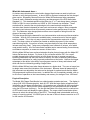
Operators’ Manual Monroe Electronics, Inc. Model 288 Charge Plate Monitor P/N 0340174 288-1/100 V1.03 100 Housel Ave PO Box 535 Lyndonville NY 14098 1-800-821-6001 585-765-2254 fax: 585-765-9330 monroe-electronics.com CONTENTS Specifications Section 1 Specifications Accessories included What this instrument does Physical description General Information Page 3 Page 3 Page 4 Page 4 Section 2 CAUTION – SHOCK HAZARD Setup – First things first SETUP SYSTEM Menu M SETUP Menu A SETUP Menu OPTION Menu Operation Page 5 Section 3 Page 6 Page 6 Page 7 Page 7 Section 4 Manual operation Programming features Automatic operation Programming features Additional features Group and location Test parameter setups Data storage and review Peak reset Plate voltage bargraph Power Charge plate Grounds Analog output Maintenance Page 8 Page 8 Page 9 Page 9 Page 10 Page 10 Page 10 Page 10 Page 10 Page 10 Page 10 Page 10 Page 10 Page 10 Section 5 Precautions Cleaning Battery Charge state indicator Calibration References Page 11 Page 11 Page 11 Page 11 Page 11 Section 6 References Page 12 Warranty Information Page 13 Repair Information Page 14 Copyright© 2000 Monroe Electronics, Inc. Printed in USA Specifications and procedures subject to change without notice 2 Section 1 SPECIFICATIONS All specifications are referred to PLate VColtage unless otherwise specified. Charging Voltage: ±10 to ±1000 volts, differential adjustable 10 volts to 100 volts in 1 volt increments Zero Stability: <100mV/sec Timer: 0.1 to 999.9 seconds in 0.1 sec increments 1000 to 9999 seconds in 1 sec increments Start Voltages: 1000 volts ±0.3% standard, adjustable between 10 and 1000 volts in 1 volt increments Stop Voltages: 100 volts ±3% standard, adjustable between 0 and 995 volts in 1 volt increments Peak Displays: ±peak voltage during float mode Power: 90-250 VAC 50/60 Hz, internal 12 volt battery with built-in charger (6 hr/charge) Voltage Output Monitor: divide by 200, 0.1%, speed of response <10ms Display: 240 x 64, character/graphic Voltage Display: 3 ½ digit, ±1.0 volt resolution Timer Display: 4 digit Accuracy: electrometer ±0.1% of reading, ±1 volt referred to input Bandwidth: 1kHz at 20Vp-p, 10Hz at 2000Vp-p Zero Drift: <100mV/sec Charge Plate Capacitance: 20pF, ±5% Plate Self-discharge: <200mV/sec Operation Temperature: 5°C to 35°C Temperature Sensor: ±2°C typ Operating RH: to 80%, non-condensing Humidity Sensor: ±5% typ from 10% to 80% RH @25°C Size: 11” x 9” x 6” Weight: 12½ lb. Specifications subject to change without notice Accessories included: Charge plate extension cable (5ft.) Ground cable Power cord Operator’s Manual 3 What this instrument does — As Ionizers were introduced to control static charges there became a need to test those ionizers to verify their performance. In about 1985 Ion Systems introduced the first charged plate monitor, followed by Monroe Electronics’ Model 268 and several other companies. These all used a fieldmeter sensing technology and became part of the ESD Association Standard 3.1. This standard spelled out the plate size, 6” x 6” and charge decay voltages, 5000V to 500V for room ionization and 1000V to 100V for bench top ionization. These worked well for years but the new technologies in the semiconductor and disk drive industries have created a demand for lower work environment voltages. Many companies now want a test instrument that will accurately measure ionizer performance to less than 10V. The fieldmeter style charged plate monitors are not capable of doing this with the degree of accuracy required. The other issues driving the demand for new instrumentation revolve around documentation and labor. With all of the instruments available today, a manual record of the test results must be created. This is the only way to provide the documentation required in an ESD audit. The sheer volume of ionizers has created an additional pressure in the modern manufacturing facility. At one time a factory may have had just a few critical areas where ionizers were being used. Today many companies have hundreds of ionizers, all of which need periodic testing. All of the instruments available require manual testing for each decay and balance sequence, an enormous amount of labor hours. With the Model 288 we have continued a design direction that we began with the Model 287 Ionizer Performance Analyzer. For those of you not familiar with the 287, it is a small, portable charged plate instrument that not only allows the user to program several key operating parameters and store the results in memory, but uses a contacting electrometer measurement technique for vastly improved performance at low levels. However the bigger advantage to this device is the ability to pre-program a series of decay and balance tests which can then be initiated by pushing a single button. With the Model 288 we have taken these advances to a higher level. The user no longer has to design tests around the limitations of the instrument. Because almost all parameters of this instrument are adjustable, the tests can be designed for optimal results and the Model 288 programmed to perform those tests. In addition this unit is completely portable, with up to six hours of operation on the internal battery and memory for storage of over 1000 tests. Physical Description: The Model 288 Charge Plate Monitor has a black powder coated metal case. The display is a large (240 X 60 Character/graphic), back-lit LCD. With this large display all pertinent test information can be shown simultaneously. All operations are controlled via the five switches on the front panel. Switch function varies depending on the selected mode and is labeled using the LCD screen (soft keys). On the right hand side of the front panel is a vertical row of LED’s which track and display the plate voltage. The range switch located below allows the user to select the voltage span of the LED’s. The charge plate is detachable and has a variety of mounting options. An RS232 port on the rear of the unit allows connection to a PC for the transfer of information. 4 Section 2 GENERAL INFORMATION Model 288 performs manual or automatic decay and balance tests for qualification and periodic verification of ionization equipment. It then stores the results and balance averages for manual tests and complete automatic test sequences up to a maximum of 1500 tests. Temperature and relative humidity are displayed real-time and recorded with the test data. All instrument functions are controlled by five key pushbuttons. In DECAY mode a built-in high voltage generator charges the plate to a voltage specified by the user – up to 1100 volts. During the test the plate will discharge toward zero in the presence of ionization. The elapsed time of decay between a selected start voltage and a selected stop voltage is displayed. In the BALANCE mode, plate voltage, test duration and + and − peak voltages are displayed. Self-tests include battery check and tests for functional errors. Memory is non-volatile. Setup and data are retained during storage. Although the Model 288 does not meet all of the requirements of the standard in the outward sense, it does allow for testing where initial voltages of 1000 volts (or less) are involved. For further details see ESD Association Standard S3.1 for Protection of Electrostatic Discharge Susceptible Items – Ionization. CAUTION When charged, the plate voltage can be in excess of 1100 volts with respect to ground. Although the charges and potentials are below those which are normally detected by human senses, A SHOCK HAZARD EXISTS. • If you are handling the plate assembly or conducting a test, which involves touching the plate, expect a shock. • Do not charge large capacitors with this device. 5 Section 3 SETUP First things first Upon power up, you are presented momentarily with an identification screen, which includes the software revision level and serial number of your unit. Within a few seconds, the MAIN screen is presented. This screen should show current date and time, ambient factors, power source information and current test number and prompt the operator to “Select Operation”. The test-numbering scheme begins with 1500 and displays the number of remaining tests. One of the menu options is SETUP. Once significant programming has been done and data taken the SETUP mode should not be tinkered with! There is no BACK button. Thus, SETUP is probably the first thing the user should become familiar with. Press the “SETUP” key. The present menu is identified in the upper left corner of the screen as “SETUP”. Menu items are: SYSTEM, MANUAL, AUTO, OPTION and (back to) MAIN. Select SYSTEM to go to the SETUP SYSTEM menu SETUP SYSTEM Menu: CLOCK – Sets the system’s real time clock. This should be set to the present local date and time in order for all future tests to be properly stamped. Once new data (if any) has been entered, press EXIT and elect to SET the clock to the time shown on the SETUP SYSTEM CLOCK screen or EDIT to change the settings or CANCEL to change nothing and return to the MAIN menu. HUMI/TEMP – Simply displays the present temperature and relative humidity. These can only be changed via connection to a PC. RAM/EE – The first screen under this option asks, “Clear all test data – Y/N?” A “Y(es)” response will permanently erase all accumulated test data from memory. The next two windows prompt a similar decision for Group/Location names and test setups. These decisions should not be taken lightly as deletions are irreversible. S/N – Displays software revision number and instrument serial number. These cannot be modified. RETURN – Returns to SETUP Menu M SETUP Menu: The M(anual) Setup screen displays a list of five user selectable manual test options. Three of them; M1, M2 and M3 may be modified. The “Factory” option uses “standard” settings and the “Test” option has settings used during factory testing of each unit. These two may not be changed. The parameters of any of the manual tests may be viewed or those of the first three edited to meet user requirements by highlighting the test and pressing the DISPLAY key. A symbol “D>” indicates which one is selected as the default test. To change the default, scroll to highlight one of the options using the NEXT key and press the DEFAULT key. The selected test will remain the default test until re-selected. Previously stored test results are not affected by a new default setting but all subsequent tests will be made with the new default until changed by this method. 6 A SETUP Menu: The A(uto) Setup screen works the same. OPTION Menu: Options are for display backlighting and auto power off. Highlight and press EDIT to view further options. The (A>) symbol indicates the current choice. Highlight desired choice and press ENTER to change or CANCEL to exit with no change. 7 Section 4 OPERATION MANUAL OPERATION: From the manual screen the user can choose to run a positive decay, negative decay or balance. Also the option exists to enter the group and location screen to select the proper designation for the ionizer under test. +/− − Decays – Once a decay test is selected the unit switches screens displaying the plate voltage, timer, group/location and test parameters. Once the test is complete a summary screen appears displaying the time of decay, test parameters, time, date, temperature, humidity and test number. From the summary screen another decay test can be run, test data history screen can be accessed or a return to the manual test screen can be selected. Balance – During the balance test the screen displays the plate voltage, test time, group/location, test parameter, average voltage and positive/negative peak voltage readings. Once the test is completed the summary screen appears with the same type of data and options available in the manual decay summary screen. Confidence Test – One of the major weaknesses in all CPM’s has been the inability to properly verify the main function of these devices, DECAY. In all the existing instruments it is possible to test the plate voltage, timer performance and other parameters but not the actual decay function. In the 288 charge plate (available in the 6 x 6 plate only) there is a test hole in the center of the plate. Simply remove the knurled thumbscrew from the back panel of the unit and insert it into this hole making sure that the head of the screw is making contact with the plate. Then run a +Decay test and a −Decay test in a nonionized environment. Both decays should be within a 6 to 8 second range. By performing this test periodically the user can be assured the unit is operating correctly. Programming features: Start Voltage – Range of 10V to 1000V, adjustable in 1V increments Charge differential – This is the difference between the start decay voltage and how much over charge the unit puts on the plate. It ranges from 10V to 100V and is adjustable in 1V increments. Stop voltage – Range of 0V to 995V, adjustable in 1V increments Test Start Delay – Range of 5sec to 15sec, adjustable in 1sec intervals. This is the time delay from when you push the start key and when the test actually begins. This allows the user to exit the area to minimize their impact on the readings. Max decay time – Range 10sec to 9999sec adjustable in 1sec intervals. If the unit does not reach the stop voltage within this time the unit will abort the test. This timer can be turned off. Balance Duration – Range of 10sec to 9999sec, adjustable in 1sec intervals. This can also be set for continuous readings with no time out. 8 AUTOMATIC OPERATION: Once the desired test parameters are set up, the user simply selects the “start” button to begin the tests. All the parameters are shown in the automatic screen. As soon as the start button is pushed the screen switches to the auto test screen and proceeds to run the prescribed number of decays and balance (only if balance is set to run via the setup). The unit moves automatically from one test to another until it has completed the programmed sequence. At the end of the tests the screen changes to display, individual decay times, average decay time, balance results, including +/− peaks and average voltage, as well as date, time, temperature, humidity, group/location. From this point you can select to run another test sequence or return to the automatic screen. As in the manual mode, the group/location button will allow you to select the appropriate label for the ionizer under test. Programming features: Start voltage – Same as manual Charge Differential – Same as manual Stop voltage – Same as manual Test Start Delay – Same as manual Max Decay Time – Same as manual Balance Duration – Same as manual Decay Cycle – Range from 1 to 10, adjustable in increments of 1. This is the number of + and – decays the unit will run in an automatic sequence. Decay Sequence – Select either the decay sequence of + − + − or + + − − for the number of cycles selected in Decay Cycle. Cycle Delay – Range from 2sec to 15sec, adjustable in 1sec increments. This is the amount of time from the finish of the last decay cycle to the start of the next. Balance (Y/N) – Select whether or not you want a balance test to automatically run at the end of the decay cycle. Continuous – This feature allows you to perform a continuous series of tests on a selectable time basis. For example, you want to run a series of decay and balance every hour for the next day. From the automatic screen select CONT, then select the desired test time interval from 1 minute to 24 hours. Once you have programmed the time, press EXIT and you will advance to the next screen. From this screen you have the option of pressing CANCEL or START. The START key begins the default automatic test sequence and will repeat that test sequence at the time interval selected. This continuous testing will continue until you stop the tests or the memory becomes full. 9 ADDITIONAL FEATURES: Group and Location – By accessing this screen the tests can be organized to reflect the ionizers’ locations. There are up to 17 Groups available, with a maximum of almost 700 locations. The total number of group/locations available will vary depending on how extensive the tests are for the individual locations (i.e. how many decays are run for each ionizer). Up to 1500 tests may be run. By using a PC connected to the units RS232 port it is possible to custom label these group/locations (i.e. Building 10 - Bench 2E). Via the same link it is then possible to download all the test results stored in the unit into a spreadsheet on the PC. Test Parameter Setups – In both the Manual and Automatic Modes there are five distinct setups. Three of these are available to the user to customize as needed. The other two are the factory and test settings, which are not adjustable. Any of these can be selected as the default test setup. Data Storage and Review – All test results are stored in the internal memory of the unit. They can be viewed through the screen or downloaded to a PC. Each test records the time, date, temperature, humidity and test results. Peak Reset – During a manual balance test where Balance Duration has been disabled the M BALANCE will show BalDur=XXXXs which means that the test will run continuously until STOPped. Pressing the PkRst key at any time will reset the displayed peak values to zero and the timer will continue to run until it reaches 999.9s then the decimal point will shift and the display will run to 9999s (or about 2 hours and 47 minutes). Beyond that, an overrun error is displayed. Plate Voltage Bar graph – Three ranges are provided with a maximum resolution of less than 10 volts for making very fast assessments of plate voltage and polarity around zero. Power – The unit will run on either AC or battery power. The internal rechargeable battery will supply up to six hours of operation. Charge Plate – A 6″ X 6″ plate comes standard with the 288. When it is detached from the base unit it comes with the ground plane plate or can be taken off as a separate item. Mounting hardware allows the plate to be attached to the side of the unit, connected to a tripod via ¼ -20 threaded insert or put into any variety of situations to measure ionization. A 5-foot extension cable comes standard with the unit. To release the detachable charge plate only, slide it forward. To remove the complete charge plate and ground plane assembly, press the release button with a suitable tool and swing the assembly slightly to the right. For those space restricted applications, there are several optional plate sizes available down to 1” x 1”. Consult factory for other sizes and availability. Grounds – A ground snap is provided on one corner of the ground plane and a ground jack is provided on the back panel. The instrument chassis is normally connected to ground via the power cord during AC operation and the ground plane is connected to the chassis when the unit is assembled. Grounding is essential to proper operation. Analog Output – An analog output jack is provided on the back panel. 10 Section 5 MAINTENANCE Precautions — User maintenance should normally be limited to keeping the instrument clean and free from physical damage. Store the instrument in its protective carrying pouch when not in use. Cleaning — Fingerprints and other contaminants may be removed from the case with a clean lint-free cloth dampened in a 70%/30% mix of clean technical grade isopropyl alcohol and de-ionized water. DO NOT use soap or detergent. Battery — Battery voltage is monitored and displayed on the MAIN screen. Normal range of operation is between 10 and 15 volts. When the battery has discharged to below 10 volts, a warning message is displayed and the instrument shuts down 15 seconds later terminating any activity in progress. Battery charge life depends on type of tests being run and the settings selected in the OPTION menu. Testing may be resumed using AC power. A complete re-charge cycle takes 4-6 hours with power off. Charge State Indicator — While the unit is connected to an AC power line and in an inactive state, the upper half (red) of the PLATE VOLTAGE bar graph serves as a battery state-of-charge indicator with maximum being a float condition and minimum implying that the battery requires further charging. The “x1” and “x2” range lights will be lit. If the power cord becomes disconnected, the LED’s will continue to report the battery status for several minutes. Calibration — Calibration is not a user function and is beyond the scope of this manual. Calibration information is available from the factory. Monroe Electronics recommends annual calibration and/or when the instrument is damaged or repaired or where called for more often by contract. We offer repair and calibration services for a fee. 11 Section 6 REFERENCES Documents associated with ionization: ESD Association Standard — ANSI/EOS/ESD-S3.1 –Ionization ESD Association Advisory – ESD ADV – 3.2 – Selection and Acceptance of Air Ionizers ESD Association (Draft) Standard – ESD DSP –3.3 – Periodic Verification of Air Ionizers ESD Association Advisory – ESD ADV – 1.0 – Glossary ESD Association Advisory – ESD ADV – 2.0 – Handbook Are available from: ESD Association, Inc. 7900 Turin Rd. Building 3, Suite 2 Rome, NY 13440-2069 Phone (315) 339-6937 Fax (315) 339-6793 [email protected] http://www.eosesd.org Monroe Electronics, Inc. does not supply copies of standards or advisories. 12 WARRANTY Monroe Electronics, Inc., warrants to the Owners, this instrument to be free from defects in material and workmanship for a period of two years after shipment from the factory. This warranty is applicable to the original purchaser only. Liability under this warranty is limited to service, adjustment or replacement of defective parts (other than tubes, fuses or batteries) on any instrument or sub-assembly returned to the factory for this purpose, transportation prepaid. This warranty does not apply to instruments or sub-assemblies subjected to abuse, abnormal operating conditions, or unauthorized repair or modification. Since Monroe Electronics, Inc. has no control over conditions of use, no warranty is made or implied as to the suitability of our product for the customer’s intended use. THIS WARRANTY SET FORTH IN THIS ARTICLE IS EXCLUSIVE AND IN LIEU OF ALL OTHER WARRANTIES AND REPRESENTATIONS, EXPRESS, IMPLIED OR STATUTORY INCLUDING BUT NOT LIMITED TO THE IMPLIED WARRANTIES OF MERCHANTABILITY AND FITNESS. Except for obligations expressly undertaken by Monroe Electronics, in this Warranty, Owner hereby waives and releases all rights, claims and remedies with respect to any and all guarantees, express, implied, or statutory (including without limitation, the implied warranties of merchantability and fitness), and including but without being limited to any obligation of Monroe Electronics with respect to incidental or consequential damages, or damages for loss of use. No agreement or understanding varying or extending the warranty will be binding upon Monroe Electronics unless in writing signed by a duly authorized representative of Monroe Electronics. In the event of a breach of the foregoing warranty, the liability of Monroe Electronics shall be limited to repairing or replacing the non-conforming goods and/or defective work, and in accordance with the foregoing, Monroe Electronics shall not be liable for any other damages, either direct or consequential. 13 RETURN POLICIES AND PROCEDURES FACTORY REPAIR Return authorization is required for factory repair work. Material being returned to the factory for repair must have a Return Material Authorization number. To obtain an RMA number, call 585-765-2254 and ask for Customer Service. Material returned to the factory for warranty repair must be accompanied by a copy of a dated invoice or bill of sale, which serves as a proof of purchase for the material. Repairs will be returned promptly. Repairs are normally returned to the customer by UPS within ten working days after receipt by Monroe Electronics, Inc. Return (to the customer) UPS charges will be paid by Monroe Electronics on warranty work. Return (to the customer) UPS charges will be prepaid and added to invoice for out-of-warranty repair work. EXPEDITED FACTORY REPAIR: All material returned to the factory by air or by an overnight service will be expedited. Expedited factory repairs will be returned to the customer by the same mode of transportation by which the material was returned to the factory for repair (i.e., material returned to the factory by an overnight service will be returned to the customer by an overnight service). NOTE: Return (to the customer) transportation expenses for expedited factory repairs will always be at the expense of the customer despite the warranty status of the equipment. FACTORY REPAIRS TO MODIFIED EQUIPMENT: Material returned to the factory for repair that has been modified will not be tested unless the nature and purpose of the modification is understood by us and does not render the equipment untestable at our repair facility. We will reserve the right to deny service to any modified equipment returned to the factory for repair regardless of the warranty status of the equipment. 14