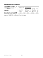
1
IONIZATION SOLUTIONS
Charge Plate Monitor
Model 280A
User’s Manual
About Simco-Ion
Simco-Ion serves the semiconductor, mass storage, flat panel
display (FPD), general electronics, automotive, medical device, and
aerospace industries with products that uniquely monitor, analyze
and control electrostatic forces, thereby improving the production
yield. Simco-Ion is a wholly-owned subsidiary of Illinois Tool Works
(ITW) with its Technology Group located in Alameda, California. For
more information about Simco-Ion visit www.simco-ion.com or call
800-367-2452. Simco-Ion is ISO 9001 and ANSI ESD S20.20
certified.
© 2011 Simco-Ion
19-0280A-M-01 Rev 3
Contents
1 Description .......................................................................... 1
1.1 Model 280A CPM..................................................................................... 2
1.2 Parts of the CPM...................................................................................... 4
1.3 Performance .......................................................................................... 10
2 Setup .................................................................................. 11
2.1 Setup and Menus................................................................................... 12
3 Operation ........................................................................... 17
3.1 Manual Operation .................................................................................. 18
3.2 Manual Test Programming Features ..................................................... 22
3.3 Automatic Operation .............................................................................. 24
3.4 Auto Sequence Test Programming Features......................................... 26
3.5 Additional Features ................................................................................ 28
4 Maintenance ...................................................................... 31
4.1 Cleaning................................................................................................. 32
4.2 Battery.................................................................................................... 33
4.3 Charge State Indicator ........................................................................... 34
4.4 Calibration.............................................................................................. 35
5 Specifications.................................................................... 37
6 Warranty & Service ........................................................... 41
7 References......................................................................... 43
Appendix A: Downloading Test Results ............................. 45
19-0280A-M-01 Rev 3
1
Description
1.1 Model 280A CPM
1.2 Parts of the CPM
1.3 Performance
19-0280A-M-01 Rev 3
1
1.1 Model 280A CPM
The Model 280A Charged Plate Monitor (CPM) is a microprocessorbased tool, providing an automated solution for measuring the
performance of air ionization systems. The unit features a simple
push-button LCD interface, and allows data transfer to computers
for precise and specific test information. All instrument functions are
controlled by five key pushbuttons.
Included with the unit is a CD with software for transferring data
between the CPM and a computer.
The Model 280A CPM allows for testing where initial voltages of
1000V (or less) are involved. For further details see ESD
Association Standard S3.1 for Protection of Electrostatic Discharge
Susceptible Items - Ionization.
The unit is completely portable, with up to six hours of operation on
the internal battery and memory for storage of over 1000 tests.
Model 280A performs manual or automatic decay and balance tests
for qualification and periodic verification of ionization equipment. It
then stores the results and balance averages for manual tests and
complete automatic test sequences up to a maximum of 1500 tests.
Temperature and relative humidity are displayed real-time and
recorded with the test data.
In DECAY mode a built-in high voltage generator charges the plate
to a voltage specified by the user - up to 1100 volts. During the test
the plate will discharge toward zero in the presence of ionization.
The elapsed time of decay between a selected start voltage and a
selected stop voltage is displayed.
In the BALANCE mode, the plate is first grounded then released
from ground and allowed to float to any voltage in response to air
ion imbalances. It displays the plate voltage, test duration, and
minimum and maximum peak voltages. (Nearby charge sources will
also induce a voltage on the floating plate.)
19-0280A-M-01 Rev 3
2
Self-tests include battery check and tests for functional errors.
Memory is non-volatile. Setup and data are retained during storage.
Caution:
When charged, the plate voltage can be in excess of 1100
volts with respect to ground. Although the charges and
potentials are below those that are normally detected by
human senses, A SHOCK HAZARD EXISTS.
• If you are handling the plate assembly or conducting a test,
which involves touching the plate, expect a shock.
• Do not charge large capacitors with this device.
19-0280A-M-01 Rev 3
3
1.2 Parts of the CPM
The 280A CPM features a large, central digital display used as an
interface for all menus, buttons, and test information. A bargraph
LED featured to the right of the central display indicates plate
voltage.
The following sections describe the CPM:
• Charge Plate Monitor
• CPM Front Panel
• CPM Back Panel
• Charge Plate
• Accessories
19-0280A-M-01 Rev 3
4
Front of Unit
Figure 1. Charge Plate Monitor
A. Ground Snap: Connects plate to the unit.
B. Decay Verification/Confidence Test Hole: Small hole uses
provided thumbscrew on the back of the unit for confidence
tests.
C. Charge Plate: Charges to specified voltage and is ion target for
decay and balance test.
D. Release Button: When pressed, the plate is released from the
unit.
E. LED Bar Graph: Three ranges are provided with a maximum
resolution of less than 10 volts for making fast assessments of
plate voltage and polarity around zero.
F. Range Switch: Selects the voltage range of the bar graph
LEDs (x1, x2, x5).
G. Soft Keys: Used to select onscreen menu choices.
H. Power on/off button.
19-0280A-M-01 Rev 3
5
I.
Central Display Screen: Interface for running tests and setting
test data.
J.
Vertical Plate Mounts: Allows plate to be mounted on the side
of the unit.
CMP Front Panel
Figure 2. CPM Front Panel
A. Power LED: Lights steadily green when CPM is powered by AC
line cord, and blinks green when powered by the battery.
B. Power On/Off Button
C. Soft Keys: Keys correspond with display screen to act as navigation buttons.
D. Range Switch: Selects the voltage range of the bar graph
LEDs (x1, x2, x5).
E. Bar Graph LED: Shows plate voltage range at all times.
F. Central Display Screen: Shows all menu activity, provides soft
key choices, displays current conditions and settings.
19-0280A-M-01 Rev 3
6
Back Panel
Figure 3. CPM Back Panel
A. Power Input Receptacle
B. RS-232 Serial Port: Connects to a computer for uploading and
downloading test data.
C. Ground Jack: Connects to provided ground cable or additional
grounding devices.
D. Temperature/Humidity Sensors: Takes measurements and
logs read-only information, accessible through the Setup menu.
E. Thumbscrew: Removes to connect to plate for confidence
tests.
F. Analog Output: The output monitors the plate voltage during
any test (otherwise set to zero). Output is 1/200th of plate
voltage.
G. Contrast Trimpot: Manual trimpot adjusts the darkness and
lightness of the screen, in addition to backlight setting.
H. Plate Connection with BNC Terminator: Connects to plate.
19-0280A-M-01 Rev 3
7
Charge Plate
Figure 4. Charge Plate
A. Ground Snap: Connects the plate to the unit.
B. Charge Plate: Top part of the whole plate is the active sensor.
C. Grounding Plate: Provides ground when correctly connected
to the main unit ground connection.
D. Front Notch: Hold plate in place.
E. Release Notch: Cutout for the release button on main unit.
F. Confidence Hole: Receives the thumbscrew stored on the
back of the unit.
G. Connection Cable: Connects to the unit cable to complete
plate connection.
Note:
The Charge Plate can be disconnected from the Grounding
Plate. For accurate readings, these plates must be connected
when using the plate remotely.
19-0280A-M-01 Rev 3
8
Supplied Accessories
Figure 5. Supplied Accessories
A. Plate Extension Cable: Provides extra distance for remote
plate placement.
B. Grounding Cable: Snaps to plate and unit for a ground connection.
C. AC Power Cord
D. Ground Extension Cable: Provides additional grounding
method and extends ground cable length.
E. Software Disk: Contains software for communicating test data
with a computer.
19-0280A-M-01 Rev 3
9
1.3 Performance
This instrument is a charged-plate monitor for evaluating the
performance of ionization systems. As such, it performs positive
and negative decay tests, and balance (offset voltage) tests to
determine if an ionization system is operating effectively. It can be
used to test all types of ionization systems as described in ESD
Association Standard ANSI/ESD STM3.1 Ionization.
Over the years new technologies have placed new demands on
both ionization systems and on the capabilities and features of the
charged-plate monitors used to evaluate them. Simco-Ion has
responded to these needs by incorporating many additional and
improved features in the Model 280A Charged-Plate Monitor. The
original Model 280A provided the following important capabilities for
people evaluating ionization systems:
• Replacement of the fieldmeter normally used to monitor the
plate voltage with a high-voltage follower amplifier to increase
accuracy and reduce zero drift.
• Wider bandwidth to evaluate AC ionization systems.
• The ability to automate commonly-repeated sequences of tests
and store their test results for future review.
• Adjustable start and stop voltages for decay tests.
• A serial interface and applications software to control ionization
tests from a computer.
The Model 280A has been improved to provide the following
capabilities:
• The ability to resolve the plate voltage with 100 mV resolution.
• Applications software to graphically display decay and balance
waveforms in real time.
• The ability to measure the performance of the latest highfrequency AC ionization systems.
19-0280A-M-01 Rev 3
10
2
Setup
2.1 Setup and Menus
19-0280A-M-01 Rev 3
11
2.1 Setup and Menus
Upon power up, you are presented momentarily with an
identification screen, which includes the software revision level and
serial number of your unit.
Within a few seconds, the MAIN screen (see Main screen below) is
presented. This screen should show current date and time, ambient
factors, power source information and current test number and
prompt the operator to "Select Operation". The test-numbering
scheme begins with 1500 and displays the number of remaining
tests.
MAIN Screen Menu
One of the menu options
is SETUP. Once
significant programming
has been done and data
taken the SETUP mode
should not be tinkered
with! There is no BACK
button. Thus, SETUP is probably the first thing the user should
become familiar with. Press the "SETUP" key.
SETUP Screen Menu
The present menu is
identified in the upper left
corner of the screen as
"SETUP".
Menu items are:
SYSTEM, MANUAL,
AUTO, OPTION and (back to) MAIN. Select SYSTEM to go to the
SETUP SYSTEM menu.
Press the "SYSTEM" key.
19-0280A-M-01 Rev 3
12
Setup SYSTEM Menu
• CLOCK - Sets the
system's real time
clock. This should
be set to the present
local date and time in
order for all future tests to be properly stamped. Once new data
(if any) has been entered, press EXIT and elect to SET the clock
to the time shown on the SETUP SYSTEM CLOCK screen or
EDIT to change the settings or CANCEL to change nothing and
return to the MAIN menu.
• HUMI/TEMP - Simply displays the present temperature and
relative humidity. These can only be changed via connection to
a PC.
• RAM/EE - The first screen under this option asks, "Clear all test
data - Y/N?" A "Y(es)" response will permanently erase all
accumulated test data from memory. The next two windows
prompt a similar decision for whether to restore defaults to
Group/Location names and test setups. These decisions
should not be taken lightly as deletions are irreversible.
• S/N - Displays software revision number and instrument serial
number. These cannot be modified.
• RETURN - Returns to SETUP Menu.
Setup MANUAL TEST Menu
In the Setup screen (see Setup screen on page 12), press
"MANUAL" key.
This screen displays a list of five user selectable manual test
options. Three of them; M.Setup 1, M.Setup 2 and M. Setup 3 may
19-0280A-M-01 Rev 3
13
be modified. The "Factory" option uses "standard" settings and the
"Test" option has settings used during factory testing of each unit.
These two may not be changed.
The parameters of any of the manual tests may be viewed or those
of the first three edited to meet user requirements by highlighting the
test and pressing the DISPLAY key. To change these parameters,
see Programming Features for Manual Tests.
A symbol "D>" indicates which one is selected as the default test.
To change the default, scroll to highlight one of the options using the
NEXT key and press the DEFAULT key. The selected test will
remain the default test until re-selected. Previously stored test
results are not affected by a new default setting but all subsequent
tests will be made with the new default until changed by this
method.
Setup AUTO SEQUENCE Menu
The Setup Auto Sequence screen works the same. It displays a list
of five user selectable manual test options. Three of them; A.Setup
1, A.Setup 2 and A. Setup 3 may be modified. The "Factory" option
uses "standard" settings and the "Test" option has settings used
during factory testing of each unit. These two may not be changed.
In the Setup screen (see Setup screen on page 12), press the
"AUTO" key.
The parameters of any of
the manual tests may be
viewed or those of the
first three edited to meet
user requirements by
highlighting the test and
pressing the DISPLAY
key. See Programming Features for Auto Sequence Tests later
in this manual.
A symbol "D>" indicates which one is selected as the default test.
To change the default, scroll to highlight one of the options using the
19-0280A-M-01 Rev 3
14
NEXT key and press the DEFAULT key. The selected test will
remain the default test until re-selected. Previously stored test
results are not affected by a new default setting but all subsequent
tests will be made with the new default until changed by this
method.
Setup OPTION Menus
Options are for display backlighting, power off, and beep settings.
The first two options will apply when the 280A unit is running on
battery.
Setup Option Menu
The first two options apply to
when the 280A unit is using
battery power.
Highlight and press EDIT to
view further options.
Backlight Menu
The (A>) symbol indicates
the current choice.
Highlight desired choice
and press ACTIVE. Then
press EXIT change.
The backlight of the display can be set to continuous lighting or shut
off in 5 minutes when it is using battery.
Auto DC Power Off Menu
When the 280A unit is
running on battery, it can be
set to run Continuously or
auto shut off in 15 minutes.
19-0280A-M-01 Rev 3
15
Highlight the option by pressing the NEXT key, then press ACTIVE.
In the Setup Option on page 15, highlight the option, then press the
EDIT key.
The Beep has three options:
• Beep On Test & Key: Beep when a key is pressed and mode
change during the test.
• Beep On Test Only: Beep only during the test when the mode
changed.
• Beep Off.
19-0280A-M-01 Rev 3
16
3
Operation
3.1 Manual Operation
3.2 Manual Test Programming Features
3.3 Automatic Operation
3.4 Auto Sequence Test Programming Features
3.5 Additional Features
19-0280A-M-01 Rev 3
17
3.1 Manual Operation
From the manual screen the user can choose to run a positive
decay, negative decay or balance. Also the option exists to enter
the group and location screen to select the proper designation for
the ionizer under test. See the Manual Test screen below.
Manual Test Screen
From the MAIN screen (see Main screen on page 12), press
MANUAL key.
+/- Decays - Once a decay test is selected the unit switches
screens displaying the plate voltage, timer, group/location and test
parameters.
+Decay Test
• SKIP: Allows user to skip test delay time.
• STOP: Abort the test or when the decay test ends, the plate
voltage reading will be continuously shown until the STOP key
is pressed.
19-0280A-M-01 Rev 3
18
Once the test is complete a summary screen appears displaying the
time of decay, test parameters, time, date, temperature, humidity
and test number. From the summary screen another decay test can
be run, test data history screen can be accessed or a return to the
manual test screen can be selected
+Decay Test Result
• REVIEW: Review the test results.
• MANUAL: Go back to MANUAL screen.
• +DECAY: Start a +Decay test.
• REVIEW: Displays the manual test results and settings as
shown in the Review Manual figure below.
Review Manual
• NxtTst: Scroll down to highlight the next test.
• ClrTst: Delete the highlighted test data.
• Return: To MANUAL screen.
19-0280A-M-01 Rev 3
19
Balance Test
STOP: Abort the test.
During the balance test the screen displays the plate voltage, test
time, group/location, test parameter, average voltage and positive/
negative peak voltage readings. Once the test is completed the
summary screen appears with the same type of data and options
available in the manual decay summary screen.
Average Voltage Overflow - The instrument cannot calculate
average voltage for indefinite periods of time. Eventually, the
average voltage computation will overflow. When this happens,
the last calculated value for the average voltage will be displayed,
and the Avg line of the display will flash, which signifies that the
average voltage computation has overflowed and is no longer
updating based on new data. The instrument continues to correctly
indicate changes to the positive and negative peak voltages, +Vp
and -Vp, respectively.
Confidence Test
One of the major weaknesses in all CPM's has been the inability to
properly verify the main function of these devices, DECAY. In all the
existing instruments it is possible to test the plate voltage, timer
performance and other parameters but not the actual decay.
function. In the 280A charge plate (available in the 6 x 6 plate only)
there is a test hole in the center of the plate. Simply remove the
knurled thumbscrew from the back panel of the unit and insert it into
this hole making sure that the head of the screw is making contact
19-0280A-M-01 Rev 3
20
with the plate. Then run a Decay test and a Decay test in a
nonionized environment. Both decays should be within a 4 to 6
second range, typical. By performing this test periodically the user
can be assured the unit is operating correctly.
19-0280A-M-01 Rev 3
21
3.2 Manual Test Programming Features
• Start Voltage - Range of 10V to 1000V, adjustable in 1V
increments
• Charge Differential - This is the difference between the start
decay voltage and how much over charge the unit puts on the
plate. It ranges from 10V to 100V and is adjustable in 1V
increments.
• Stop Voltage - Range of 0V to 995V, adjustable in 1V
increments
• Test Start Delay - Range of 0sec to 15sec, adjustable in 1sec
intervals. This is the time delay from when you push the start
key and when the test actually begins. This allows the user to
exit the area to minimize their impact on the readings.
• Max Decay Time - Range 10sec to 9999sec adjustable in 1sec
intervals. If the unit does not reach the stop voltage within this
time the unit will abort the test. This timer can be turned off.
• Balance Duration - Range of 10sec to 9999sec, adjustable in
1sec intervals. This can also be set for continuous readings with
no time out.
Average Voltage Overflow - The instrument cannot calculate
average voltage for indefinite periods of time. Eventually, the
average voltage computation will overflow. When this happens,
the last calculated value for the average voltage will be displayed,
and the Avg line of the display will flash, which signifies that the
average voltage computation has overflowed and is no longer
updating based on new data. The instrument continues to correctly
indicate changes to the positive and negative peak voltages, +Vp
and -Vp, respectively.
19-0280A-M-01 Rev 3
22
SETUP - MANUAL - M.Setup 1
From the MAIN Screen (see figure below), press SETUP MANUAL. Then highlight the M.Setup 1, press DISPLAY. The
following screen will appear.
Press NEXT or PREV to
highlight the item, then
press EDIT to make
changes.
When finish, press SAVE
to store the new settings.
Or press CANCEL to discard the changes.
19-0280A-M-01 Rev 3
23
3.3 Automatic Operation
Once the desired test parameters are set up, the user simply selects
the "start" button to begin the tests. All the parameters are shown
in the automatic screen
Auto Sequence Test
From the MAIN screen, press AUTO.
• Start: To start the auto sequence tests.
• Grp/Loc: To select another group and location.
• Cont: Perform auto sequence test Continuously. This will
prompt for time interval between each auto sequence tests.
• MAIN: Back to MAIN screen.
As soon as the start button is pushed the screen switches to the
auto test screen and proceeds to run the prescribed number of
decays and balance (only if balance is set to run via the setup). The
unit moves automatically from one test to another until it has
completed the programmed sequence. At the end of the tests the
screen changes to display, individual decay times, average decay
time, balance results, including / peaks and average voltage, as
well as date, time, temperature, humidity, group/location. From this
point you can select to run another test sequence or return to the
automatic screen.
19-0280A-M-01 Rev 3
24
As in the manual mode, the group/location button will allow you to
select the appropriate label for the ionizer under test.
Auto Sequence Tests
• SKIP: Allows user to skip start delay time.
• STOP: stop the test.
When the auto sequence tests are finished, data will be shown as
below.
Auto Sequence Test Review
• NxtCyc: Highlight the next data row.
• MAIN: Back to MAIN screen.
• AUTO: Start another auto sequence test.
19-0280A-M-01 Rev 3
25
3.4 Auto Sequence Test
Programming Features
• Start Voltage - Same as manual
• Charge Differential - Same as manual
• Stop Voltage - Same as manual
• Test Start Delay - Same as manual
• Max Decay Time - Same as manual
• Balance Duration - Same as manual
• Decay Cycle - Range from 1 to 10, adjustable in increments of
1. This is the number of and - decays the unit will run in an
automatic sequence.
• Decay Sequence - Select either the decay sequence of or
for the number of cycles selected in Decay Cycle.
• Cycle Delay - Range from 2 sec to 15 sec, adjustable in 1 sec
increments. This is the amount of time from the finish of the last
decay cycle to the start of the next.
• Balance (Y/N) - Select whether or not you want a balance test
to automatically run at the end of the decay cycle.
• Continuous - This feature allows you to perform a continuous
series of tests on a selectable time basis. For example, you
want to run a series of decay and balance every hour for the
next day. From the automatic screen select CONT, then select
the desired test time interval from 1 minute to 24 hours. Once
you have programmed the time, press EXIT and you will
advance to the next screen. From this screen you have the
option of pressing CANCEL or START. The START key begins
the default automatic test sequence and will repeat that test
sequence at the time interval selected. This continuous testing
will continue until you stop the tests or the memory becomes
full.
From the MAIN Screen (see Main screen on page 12), press
SETUP - AUTO. Then highlight the A.Setup 1, press DISPLAY. The
following screen will appear.
19-0280A-M-01 Rev 3
26
Auto Sequence Test Setup
Press NEXT or PREV to
highlight the item, then
press EDIT to make
changes.
When finish, press SAVE
to store the new settings
or press CANCEL to discard the changes.
19-0280A-M-01 Rev 3
27
3.5 Additional Features
Group and Location
By accessing this screen the tests can be organized to reflect the
ionizers' locations. There are up to 17 Groups available, with a
maximum of almost 700 locations. The total number of group/
locations available will vary depending on how extensive the tests
are for the individual locations (i.e. how many decays are run for
each ionizer). Up to 1500 tests may be run. By using a PC
connected to the units RS232 port it is possible to custom label
these group/locations (i.e. Building 10 - Bench 2E). Via the same
link it is then possible to download all the test results stored in the
unit into a spreadsheet on the PC
Select Group/Location for the Test
• NEXT: To highlight the next Group.
• NXTLOC: Select the same group, next location from the current
one.
• CANCEL: Cancel the selection.
• SELECT: Select the highlighted group. This will lead to select
location screen.
19-0280A-M-01 Rev 3
28
Test Parameter Setups
In both the Manual and Automatic Modes there are five distinct
setups. Three of these are available to the user to customize as
needed. The other two are the factory and test settings, which are
not adjustable. Any of these can be selected as the default test
setup.
Data Storage and Review
All test results are stored in the internal memory of the unit. They
can be viewed through the screen or downloaded to a PC. Each
test records the time, date, temperature, humidity and test results.
Review Data
From MAIN screen (see
Main Screen on page 12),
press DATA.
• RvwMan: Review
Manual test data. See
Review Manual on
page 19.
• RvwAuto: Review Auto sequence data. See Auto Sequence
Test Review on page 25.
• GRP/LOC: Select group/location.
• CLR: Erase data.
• MAIN: Back to MAIN screen.
Peak Reset
During a manual balance test where Balance Duration has been
disabled the M BALANCE will show BalDur=XXXXs which means
that the test will run continuously until STOPped. Pressing the
PkRst key at any time will reset the displayed peak values to zero
and the timer will continue to run until it reaches 999.9s then the
decimal point will shift and the display will run to 9999s (or about 2
hours and 47 minutes). Beyond that, an overrun error is displayed.
19-0280A-M-01 Rev 3
29
Plate Voltage Bar Graph
Three ranges are provided with a maximum resolution of less than
10 volts for making very fast assessments of plate voltage and
polarity around zero.
Power
The unit will run on either AC or battery power. The internal
rechargeable battery will supply up to six hours of operation.
Charge Plate
A 6 X 6 plate comes standard with the 280A. When it is detached
from the base unit it comes with the ground plane plate or can be
taken off as a separate item. Mounting hardware allows the plate to
be attached to the side of the unit, connected to a tripod via ¼ -20
threaded insert or put into any variety of situations to measure
ionization. A 5-foot extension cable comes standard with the unit.
To release the detachable charge plate only, slide it forward. To
remove the complete charge plate and ground plane assembly,
press the release button with a suitable tool and swing the assembly
slightly to the right.
For those space restricted applications, there are several optional
plate sizes available down to 1" x 1". Consult factory for other sizes
and availability.
Grounds
A ground snap is provided on one corner of the ground plane and a
ground jack is provided on the back panel. The instrument chassis
is normally connected to ground via the power cord during AC
operation and the ground plane is connected to the chassis when
the unit is assembled. Grounding is essential to proper operation.
Analog Output
An analog output jack is provided on the back panel
19-0280A-M-01 Rev 3
30
4
Maintenance
4.1 Cleaning
4.2 Battery
4.3 Charge State Indicator
4.4 Calibration
19-0280A-M-01 Rev 3
31
4.1 Cleaning
User maintenance should normally be limited to keeping the
Precaution: instrument clean and free from physical damage. Store the
instrument in its protective carrying pouch when not in use.
Fingerprints and other contaminants may be removed from the case
with a clean lint-free cloth dampened in a 70/30% mix of clean
technical grade isopropyl alcohol and de-ionized water.
Note:
Do not use soap or detergent to clean the case of the CPM.
19-0280A-M-01 Rev 3
32
4.2 Battery
Battery voltage is monitored and displayed on the MAIN screen.
Normal range of operation is between 10V and 15V. When the
battery has discharged to below 10V, a warning message is
displayed and the instrument shuts down 15 seconds later
terminating any activity in progress. Battery charge life depends on
type of tests being run and the settings selected in the OPTION
menu. Testing may be resumed using AC power.
A complete re-charge cycle takes 4-6 hours with power off.
19-0280A-M-01 Rev 3
33
4.3 Charge State Indicator
While the unit is connected to an AC power line and in an inactive
state, the upper half (red) of the PLATE VOLTAGE bar graph serves
as a battery state-of-charge indicator with maximum being a float
condition and minimum implying that the battery requires further
charging. The "x1" and "x2" range lights will be lit. If the power cord
becomes disconnected, the LED's will continue to report the battery
status for several minutes.
19-0280A-M-01 Rev 3
34
4.4 Calibration
Calibration is not a user function and is beyond the scope of this
manual. Simco-Ion recommends the unit be calibrated on an annual
basis, and/or when the instrument is damaged or repaired, or
where called for more frequently by contract. Simco-Ion offers
repair and calibration services for a fee. Additional information on
CPM Calibration services can be obtained from the factory.
19-0280A-M-01 Rev 3
35
19-0280A-M-01 Rev 3
36
5
Specifications
All specifications are referred to plate voltage unless otherwise
specified.
Display
240 x 64 character/graphic
Voltage
3.5 digit display (Decay and Peak reading)
Accuracy
±0.1% of reading ±3 lsd
Resolution
1V for readings >99V; 0.1V for reading <100V
Time
4 digit display
Accuracy
0.1% of reading ±1 lsd
Resolution
0.1 sec for readings <1000 sec; 1 sec for reading >999 sec
Electrometer
Dynamic Range
±1200V
Follower Error
<10 mV
Speed of Response
<10 msec for 1 kV to 0V (90-10%)
Bandwidth
-3 db @ 1 Khz 20Vp-p; 3 db @ 10 Hz 2000 Vp-p
Noise
<12 mVrms
Monitor Output
Divide by 200
Accuracy Output
0.1% of reading ±12 mV
Impedance
1 kOhms
19-0280A-M-01 Rev 3
37
Start Voltages
1000V ±0.3%, standard
Range
±10 to ±1000V
Resolution
Settable to 1V
Accuracy
0.3% of setting ±2.5V
Stop Voltages
100V ±3%, standard
Range
0 to ±995V
Resolution
Settable to 1V
Accuracy
0.3% of setting ±2.5V
Charge Voltage
Range
10V to 100V above the start voltage
Resolution
Settable to 1V increments
Accuracy
0.3% of setting ±2.5V
Charge Plate
Capacitance
20 pF, ±5% (not including strays)
Zero Drift
<100 mV/sec (no incident ion flow)
Self Discharge
<200 mV/sec
Peak Detector
Balance Test
Bandwidth
<10 Hz (pulse width >50 msec less 10% error typical)
Average Voltage
Overflow
When averaging overflows, the last calculated value for the average
voltage will be displayed, and the Avg line of the display will flash,
indicating an overflow; the instrument continues to correctly indicate
changes to the positive and negative peak voltages, +Vp and -Vp,
respectively
Temperature Sensor
Range
0-50°C
Accuracy
±2°C (typ)
Humidity Sensor
Range
10-80% RH @ 25°C
Accuracy
±5% ( typ)
Operating
Temperature
5°C to 35°C
Humidity
to 80%, non-condensing
Battery Life
6 hours
Charge Time
<8 hrs to >90% capacity
19-0280A-M-01 Rev 3
38
Power
Voltage
90-250 VAC; 50/60 Hz
Wattage
<12W operating
CPM
Size
Weight
Certification
19-0280A-M-01 Rev 3
11 x 9 x 6 in. (280 x 229 x 152 mm)
12.5 lb (5.7 kg)
CE
39
19-0280A-M-01 Rev 3
40
6
Warranty & Service
Simco-Ion provides a limited warranty for the Charge Plate Monitor
Model 280A. New products manufactured or sold by Simco-Ion are
guaranteed to be free from defects in material or workmanship for a
period of two (2) years from date of initial shipment. Simco-Ion
liability under its new product warranty is limited to servicing
(evaluating, repairing, or replacing) any unit returned to Simco-Ion
that has not been subjected to misuse, neglect, lack of routine
maintenance, repair, alteration, or accident. In no event shall
Simco-Ion be liable for collateral or consequential damages.
Consumable items such as, but not limited to, emitter points, emitter
wire, batteries, filters or light bulbs are only covered under this
warranty if received defective at initial use with the new product.
To obtain service under this warranty, please contact Simco-Ion
Technical Support at [email protected] or 510-2170470.
19-0280A-M-01 Rev 3
41
19-0280A-M-01 Rev 3
42
7
References
Documents associated with ionization:
• ESD Association Standard: ANSI/ESD STM3.1- Ionization
• ESD Association Advisory: ESD ADV3.2 - Selection and
Acceptance of Air Ionizers
• ESD Association: (Draft) Standard - ANSI/ESD SP3.3 Periodic Verification of Air Ionizers
• ESD Association Advisory: ESD ADV1.0 - Glossary
Are available from:
ESD Association, Inc.
7900 Turin Rd.
Building 3, Suite 2
Rome, NY 13440-2069
Phone (315) 339-6937
Fax (315) 339-6793
[email protected]
http://www.eosesd.org
Simco-Ion does not supply copies of standards or advisories.
19-0280A-M-01 Rev 3
43
19-0280A-M-01 Rev 3
44
APPENDIX A
Downloading
Test Results
19-0280A-M-01 Rev 3
45
To install the software, insert the CD that came with your CPM into
your CD/DVD drive. If the install does not run open the CD and
double click on “Install-280A-vXXX”(where “XXX” is the software
version)
Follow the instruction on the screen.
Connect your CPM to a serial port on your PC (or Laptop) and
double click the application icon
on the desktop. Or go to
Start -> Programs -> 280A-> ION-280A
The software will try to locate an attached CPM
if the software did not find a CPM the below window will popup.
19-0280A-M-01 Rev 3
46
Select the comport that you connected the CPM (be sure the CPM
is on)
Click the
screen:
button to continue to main menu
19-0280A-M-01 Rev 3
47
to Download test data click on
next
,
checking “Include test setup for the Data”, will also download the
test setup information from the CPM. Click
download...
19-0280A-M-01 Rev 3
48
to start the
Navigate to where you what the file stored, select a file name and
press
and the download will begin.
After the download is complete, your will be given a chance to view
the data
the Test data will be stored in an Microsoft excel compatible, tab
delimited format
A sample report with “Include test setup for the Data” unchecked.
19-0280A-M-01 Rev 3
49
ION 280 Charge Plate Monitor
Firmware Ref.2.05 8/5/2009 S/N 059553
Download date: 9/21/2010 8:25:13 AM
Filename: C:\288data\testdata.xls
Group
PlugPlay
PlugPlay
PlugPlay
PlugPlay
PlugPlay
PlugPlay
Location Comment
FlowHood
FlowHood
FlowHood
FlowHood
FlowHood
FlowHood
Type(1)
A+D01
A-D01
A+D01
A-D01
A+D01
A-D01
Date(M/D Time(H:M Temp(C) Humi(%RH+Decay(s -Decay(seEndV(2) Bal(+Vp) Bal(-Vp) Bal(Vavg)
8/20/2010 #######
26
36
11.1 8/20/2010 #######
26
36 14.2
8/20/2010 #######
26
36
20.6 8/20/2010 #######
26
36 18.7
8/20/2010 #######
26
36
9.5 8/20/2010 #######
26
36 27.7
-
sample report with “Include test setup for the Data” checked.
ION 280 Charge Plate Monitor
Firmware Ref.2.05 8/5/2009 S/N 059553
Download date: 9/21/2010 10:24:44 AM
Filename: C:\288data\testdata2.xls
Group
PlugPlay
PlugPlay
PlugPlay
PlugPlay
PlugPlay
PlugPlay
Location Comment
FlowHood
FlowHood
FlowHood
FlowHood
FlowHood
FlowHood
Type(1)
A+D01
A-D01
A+D01
A-D01
A+D01
A-D01
Date(M/D Time(H:M:S) Temp(C) Humi(%RH+Decay(s -Decay(seEndV(2) Bal(+Vp) Bal(-Vp) Bal(Vavg) StartV
StopV
ChrgDif.V StartDelayCycleDela BalDur(se MaxDecayAutoSeq #OfCycle EndBal
8/20/2010 10:02:58 AM
26
36
11.1 1000
100
50
5
5
60
300 +-+1N
8/20/2010 10:02:58 AM
26
36 14.2
1000
100
50
5
5
60
300 +-+1N
8/20/2010 12:05:22 PM
26
36
20.6 1000
100
50
5
5
60
300 +-+1N
8/20/2010 12:05:22 PM
26
36 18.7
1000
100
50
5
5
60
300 +-+1N
8/20/2010 1:28:05 PM
26
36
9.5 1000
100
50
5
5
60
300 +-+1N
8/20/2010 1:28:05 PM
26
36 27.7
1000
100
50
5
5
60
300 +-+1N
19-0280A-M-01 Rev 3
50
Notes
19-0280A-M-01 Rev 3
51
Notes
19-0280A-M-01 Rev 3
52
Technology Group
1750 North Loop Rd., Ste 100
Alameda, CA USA 94502
Tel: 510-217-0600
Fax: 510-217-0484
Toll free: 800-367-2452
Sales services: 510-217-0460
Tech support: 510-217-0470
[email protected]
[email protected]
[email protected]
[email protected]
www.simco-ion.com
19-0280A-M-01 Rev 3