1
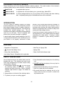
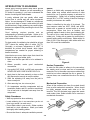
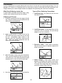
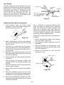
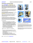
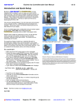
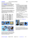
DELUXE ELECTRONIC SOLDERING STATION KIT
MODEL SL-5K
MODEL SL-5K-40
MODEL SL-5K-SPL
Assembly and Instruction Manual
Elenco Electronics, Inc.
Copyright © 2000 Elenco Electronics, Inc.
Revised 2001
REV-B
753112
SOLDERING STATION KIT MODELS
These instructions are for the following electronic soldering stations. The model number of the electronic
soldering station that you have received, is marked on the end of the carton.
Model SL-5K
is supplied without an iron.
Model SL-5K-40
is supplied with a 40 watt soldering iron, grounded plug, Model SR-6.
Model SL-5K-SPL
is custom packaged with an iron of your choice of 25 to 60 watts, and other soldering
aids. A separate packing slip of the additional items will be enclosed.
INTRODUCTION
The SL-5 series of soldering stations are quality
products designed to give the professional, student
and hobbyist greater control in quality soldering a
broad range of soldering situations. The stations are
available with variable wattage irons. The AC
receptacle on the back of the station allows soldering
irons of up to 300 watt. The AC receptacle also
allows irons to be easily changed or replaced.
ground, if your hot and ground wires are reversed, or
if your hot and neutral wires are reversed. This is
important when working with today's static-sensitive
electronic components and is critical for safety when
working with high-voltage circuitry.
If you have received a solder practice kit SP-1A or
SP-3B with this kit, do the solder practice first before
assembling the solder station. Learning to solder
properly is essential to good working electronic
circuitry.
A special safety feature (patent pending) of the SL-5
is its ground fault detection circuit, which warns you if
your station is not properly connected to earth
FEATURES
• Regulation of Temperature
• Steel Tray for Sponge Pad
•
• Sponge Pad
Ground Fault Safety Circuit
• Heavy Steel, Non-Slip Base
• Power On/Off with Indicator Light
• Iron Holder Funnel - Reversible, left or right side
SAFETY PRECAUTIONS
Like all electrical devices, the solder station must be
handled with care. The soldering iron and tip can
reach high temperatures and these simple safety
rules should be followed.
4. Keep flammable material away from the soldering
iron.
5. DO NOT cool iron by dipping it into any liquid or
water.
1. If the problem indicator light
is on, do not use
the soldering station at that outlet. A wiring
problem may exist at the outlet. Refer to Problem
Indicator Light Section on page 3 for details on
problems.
6. Always assume that the tip is hot to avoid burns.
7. Work in an area that is well ventilated.
8. Be careful that the hot soldering iron tip or the
barrel of the iron does not come in contact with
any electrical cord.
2. Keep children out of reach of the soldering station.
3. To protect your eyes, use safety goggles.
-1-
SOLDER PRACTICE KIT
If the soldering station contains a soldering iron,
remove only the soldering iron, the soldering station
plastic housing, the sponge tray, sponge and the
soldering iron holder (funnel) from the station box.
Assemble them as shown in Figure 1.
Soldering Iron
Holder (funnel)
Soldering Station
Plastic Housing
You will temporarily use the station parts as a
soldering iron stand until you have completed your
solder practice and some of the assembly of your
station. Proceed as follows:
1) Assemble the metal base to the soldering station
body hold it in place temporarily by taping the base
to the body with Scotch® tape (see Figure 2).
2) Insert the soldering iron holder (funnel) on either
the right or the left side.
Sponge
Tray
3) Insert the tray into the body of the soldering
station.
Figure 1
4) Wet the sponge with preferably distilled or tap
water and then place it into the tray.
5) Plug the soldering iron into an AC outlet and
place the soldering iron into the iron holder
(funnel).
6) You will now tin the tip by applying solder to the tip
as it heats up. DO IT before the tip becomes too
hot.
7) You are now ready to do your solder practice
SP-1A or SP-3B or begin to assemble the
circuitry of your soldering station.
Notice: Read Introduction to Soldering on page 4
before proceeding with your project.
Base
Scotch® Tape
Figure 2
-2-
PROBLEM INDICATOR LIGHT
The SL-5 is equipped with a problem indicator light.
The indicator turns on when the following problems
are present at the outlet that it is plugged into:
1. Open Ground
2. Hot and Ground Reversed (bright when switch is
OFF, Dim with switch ON)
3. Hot and neutral reversed (dim when switch is
OFF, bright with switch ON)
The Problem indicator will not test for:
1. Ground and Neutral reversed
2. Ground and Neutral wired together
3. Ground Fault Interrupter (G.F.I) in circuit
The problem indicator light is NOT a comprehensive
diagnostic instrument. Incorrect wiring of the output
plug for soldering iron will NOT be detected by this
circuit. Refer all indicated problems to Instructor or
Qualified Electrician.
If the On/Off switch does not light, when unit is
turned on this may indicate the following:
1. The Soldering Station is not plugged into a live
receptacle
2. An open Neutral
3. An open Hot Lead
SOLDERING IRONS
Iron wattage varies up to 300 watt. For working on
PC boards, irons ranging from 15 to 40 watt is
suitable. If a heavy-duty soldering iron is required, a
60 watt iron should be considered. If you use an iron
with a higher wattage rating than 40 watt, you may
damage the copper tracks on the PC board. The
higher wattage irons are best suited for heavy-duty
electrical connections.
Tin Plating
Chrome Plating
Iron Plating
Copper
Figure 3
Tip Cleaning
A good clean solder tip makes soldering much
easier. The tip should be tinned by lightly coating it
with solder to prevent it from oxidizing. The tip can
become pitted (black spots) from normal use. It is
important to clean the tip by wiping it with a wet
sponge or rag. For tips that need a good cleaning,
the tip tinnier and cleaner (#TTC1) should be used.
Never use a file or abrasive material to clean the
tip. Using such methods will damage the plating and
ruin the tip. Do not remove the excess solder from
the tip before storing. The excess solder will prevent
oxidation.
Soldering Iron Tip
The tip is the very important part of the iron. The
material that the tip is made from is an essential
factor. The soldering iron tip contains four different
metals as shown in Figure 3. The core consists of
copper. Since the copper is a soft material, it is
plated with iron. Chrome plating is used on the area
where no soldering takes place to prevent oxidation.
Then the tip is plated with tin, because it can be
easily cleaned.
Note: If you do not have much experience soldering, or no
experience at all, you should try building one of our solder practice
kits (Model SP-1A or SP-3B). Doing so will enhance your ability to
solder, give you a better understanding of the basics of soldering,
and reduce the risk of solder errors while building this kit.
-3-
INTRODUCTION TO SOLDERING
Solder
Almost every electronic device today has a printed
circuit (PC) board. Whether you are assembling a
PC board or repairing it, you must understand the
basics of working with these boards.
Solder is a fusible alloy composed of tin and lead.
Some solder may contain small amounts of other
material for use in special purposes to enhance its
characteristics. Solder has a melting temperature
around 361OF to 370OF, making it ideal for forming a
metallic joint between two metals.
A poorly soldered joint can greatly effect small
current flow in circuits and can cause equipment
failure. You can damage a PC board or a component
with too much heat or cause a cold solder joint with
insufficient heat. Sloppy soldering can cause bridges
between two adjacent foils preventing the circuit from
functioning.
Solder is identified by the ratio of tin-to-lead. The
most common ratios are 63/37, 60/40, and 40/60.
Solder with a greater tin content melts at a lower
temperature, takes less time to harden, and
generally makes it easier to do a good soldering job.
The ratio of tin is a main factor in the strength of the
solder joint. Solder with a greater tin content has a
greater holding ability under stress. Solder with a tin
ratio of 60% is the strongest, while solder with less
than 30% would be undesirable.
Good soldering requires practice and an
understanding of soldering principles. Solder (a tinlead fusible alloy) is used to form a metallic union or
joint between two metals.
For best results, the soldering iron should be at least
100OF above the melting point of solder (361OF).
Generally, a minimum temperature of 650OF is
desirable for printed circuit boards, while higher
temperatures are needed for proper soldering to
heavier terminals.
Solder
Listed below are some basic steps that should be
followed to make good solder joints.
Rosin Core
1. Make sure that the part that is to be soldered is
clean.
2. Where possible,
connections.
make
good
Figure 4
mechanical
Surface Preparation
In order for the solder to adhere to the connection,
the metals must be clean and free of nonmetallic
materials. Flux in the solder can remove oxides from
metal but not other materials like dirt or grease. To
remove these, use a small steel brush or fine emery
cloth.
3. Use quality 63/37, 60/40, or 40/60 rosin core solder.
NEVER USE ACID CORE SOLDER OR FLUX.
4. Apply heat to the base material or wires so that
they become hot enough to melt the solder.
5. Slide the soldering iron away from the joint to
leave a neat joint.
Mechanical Connection
6. After removing iron, do not move joint.
When all the surfaces are clean, the metals should
have a solid mechanical connection. Wires should
be tightly wrapped around each other or to the
terminal. This will eliminate large gaps that create
weak solder joints. Solder should not be used as a
mechanical connection.
7. On temperature sensitive components such as
transistors, diodes, and IC’s, avoid too much heat.
Use a heat sink to dissipate heat away from the
component.
Safety Procedures
• Wear eye protection when soldering.
Solder
Terminal
• Locate soldering iron in an area where you do not
have to go around it or reach over it.
Wire
• Do not hold solder in your mouth. Solder contains
lead and is a toxic substance. Wash your hands
thoroughly after handling solder.
Figure 5
• Be sure that there is adequate ventilation present.
-4-
SOLDERING
A poorly soldered joint can greatly affect small current flow in circuits and can cause equipment failure. You can
damage a PC board or a component with too much heat or cause a cold solder joint with insufficient heat.
Sloppy soldering can cause bridges between two adjacent foils preventing the circuit from functioning.
What Good Soldering Looks Like
Types of Poor Soldering Connections
A good solder connection should be bright, shiny,
smooth, and uniformly flowed over all surfaces.
1. Insufficient heat - the solder will not flow onto
the lead as shown.
Soldering a PC board
Rosin
1. Solder all components from the copper foil side
only. Push the soldering iron tip against both the
lead and the circuit board foil.
Soldering Iron
Component Lead
Soldering iron positioned
incorrectly.
Foil
2. Insufficient solder - let the solder flow over the
connection until it is covered. Use just enough
solder to cover the connection.
Circuit Board
2. Apply a small amount of solder to the iron tip.
This allows the heat to leave the iron and onto
the foil. Immediately apply solder to the
opposite side of the connection, away from the
iron. Allow the heated component and the
circuit foil to melt the solder.
Solder
Gap
Component Lead
Soldering Iron
Solder
3. Excessive solder - could make connections
that you did not intend to between adjacent foil
areas or terminals.
Foil
Solder
3. Allow the solder to flow around the connection.
Then, remove the solder and the iron and let the
connection cool. The solder should have flowed
smoothly and not lump around the wire lead.
Solder
4. Solder bridges - occur when solder runs
between circuit paths and creates a short circuit.
This is usually caused by using too much solder.
To correct this, simply drag your soldering iron
across the solder bridge as shown.
Soldering Iron
Foil
Soldering Iron
4. Here is what a good solder connection looks like.
Foil
-5-
Drag
Heat Sinking
Electronic components such as transistors, IC’s, and
diodes can be damaged by the heat during soldering.
Heat sinking is a way of reducing the heat on the
components while soldering. Dissipating the heat
can be achieved by using long nose pliers, an
alligator clip, or a special heat dissipating clip. The
heat sink should be held on the component lead
between the part and the solder joint.
Soldering Iron
Solder
PC Board
Heat Sink
(this can be ordered as part of
Elenco’s Solder Ease Kit Model
SE-1 - see Page 6).
Heat Sensitive
Component (Diode)
Figure 6
Soldering Surface Mount Components
After a component is completely soldered, each
solder joint should be inspected with a magnifying
glass. If the solder has not flowed smoothly, a bad
solder joint is indicated. This occurs when the
component and pad have not been heated sufficiently.
To correct, reheat the connection and if necessary
add a small amount of additional solder.
1. Using tweezers, place the surface mount
component on the PC board pads and secure in
place with tape (see Figure 7A).
Tape
Iron
Another way to solder surface mount components is
as follows:
Figure 7A
1. Apply a small amount of solder to the soldering
iron tip as shown in Figure 7B.
Solder
2. Apply a small amount of solder to the soldering
iron tip. This allows the heat to leave the iron and
flow onto the foil.
2. Using tweezers, hold the component on the PC
board pads.
3. Apply the soldering iron simultaneously to the
component and pad and allow the solder to flow
around the component.
3. Place the iron in contact with the PC board foil.
Apply a small amount of solder simultaneously to
the foil and the component and allow them to
melt the solder.
4. Remove the soldering iron and allow the
connection to cool.
4. Remove the iron and allow the solder to cool. The
solder should have flowed freely and not lump up
around the component.
Tweezers or Pliers
5. Remove the tape and solder the other side of the
component.
When soldering the transistors, diodes and
integrated circuits, the following procedure may
be used:
Soldering Iron
Surface Mount Component
1. Place the component on the PC board pads and
secure in place with tape.
Solder
2. Apply a small amount of solder to the soldering
iron tip.
Figure 7B
3. Place the soldering iron tip on top of the
component lead to be soldered and apply solder
simultaneously to the lead and the PC board foil.
4. Remove the iron and allow the solder to cool. The
solder should have flowed freely and not lump up
around the component.
-6-
CIRCUIT OPERATION
Anode
P N P N
THYRISTOR
A thyristor is a controlled silicon diode which is not conductive in
the reversed direction. It will only conduct in the forward direction
when they are triggered by short pulse or steady voltage applied
between the gate and cathode terminals (see Figure 8).
A thyristor family of semiconductors consists of several useful
devices. The most commonly used are silicon-controlled
rectifiers (SCR), triacs, and diacs. They can be thought of as a
solid-state switch with three or more PN junctions.
TRIAC
The block construction of a triac is shown in Figure 9. The triac
is like two SCRs connected in parallel in the opposite direction.
The construction of the triac allows it to conduct in either
polarity. The triac has only one gate that can be triggered by
either polarity. The main function is to control power bilaterally
in an AC circuit.
Gate
Anode
SCR
Current
Flow
Gate
Cathode
Figure 8
N P N P
MT2
N
MT1
N
Gate
MT2
Triac
Current
Flow
Gate
MT1
Figure 9
DIAC
MT1
The block construction of a diac or bi-directional diode is shown
in Figure 10. The diac will not conduct in either direction until its
“breakover voltage” (VBO) is exceeded. Breakover points range
from 20-36 volt. When this accrues, the device will conduct until
the voltage across its terminals is below the “breakback voltage”
(VBB) typical 6V.
Cathode
N P N
MT2
MT1
Diac
Current
Flow
MT2
Figure 10
CIRCUIT OPERATION
The circuit in Figure 11 is a basic full-wave triac phase control
circuit. The variable resistor VR1 and capacitor C1 are a
single-element phase shift network. When the voltage across
C1 reaches break-over voltage of the diac D3, C1 is then
partially discharged by the diac into the triac gate. The triac is
then triggered (turned on) and conducts for the remainder of
the half-cycle. The problem with this circuit is hysteresis, or
snap back effect. The circuit will not operate until the resistor
VR1 is turned up to an intermediate point. As the resistance of
VR1 is decreased, the voltage across the capacitor C1
increases until the diac first fires at point A, the end of the half
cycle. After the gate is triggered the capacitor voltage drops
suddenly to approximately half the trigger voltage, causing a
different initial condition. The capacitor charges to the diac
trigger voltage at point B in the next half cycle.
C1
.082µF
Triac
120V
(60Hz)
Diac
VR1
250kΩ
Figure 11
Black
Triac
120V
(60Hz)
D3
VR1
250k
Figure 12
-7-
D1
Diac
Load
The addition of resistor R1 and diodes D1 and D2 in Figure 12
will eliminate the hysteresis problem. The additional parts reset
the timing capacitor to the same level after each positive half
cycle. This provides a uniform initial condition for the timing
capacitor.
C1
.082µF
D2
R1
15kΩ
PARTS LIST
If you have completed the solder practice SP-1A or SP-3B (optional) and have assembled your soldering iron
stand, you may now proceed to assemble your solder station.
Contact Elenco Electronics (address/phone/e-mail is at the back of this manual) if any parts are missing or
damaged. DO NOT contact your place of purchase as they will not be able to help you.
Resistors
Qty
1
1
1
1
Symbol
R3
R2
R1
VR1
Description
Resistor 15kΩ 5% 1/4W (brown-green-orange-gold)
Resistor 15kΩ 5% 1W (brown-green-orange-gold)
Resistor 27kΩ 5% 1W (red-violet-orange-gold)
Potentiometer 250kΩ PC Mount
Qty
1
Symbol
C1
Description
.082µF 200V Mylar
Part #
151500
151502
152702
192639
Capacitors
Part #
248219
Semiconductors
Qty
4
1
1
1
Symbol
D1 - D4
LED
TR1
D5
Description
1N4004
Light Emitting Diode (LED) Red
Triac BTA12400B / BTA08400B
Diac DB3 (marked D3 on PC board)
Part #
314004
350002
364012
365761
Miscellaneous
Qty
1
1
1
1
1
1
1
1
1
1
1
4
1
Description
PC Board
Switch Rocker Illuminated
Neon (Symbol: LP)
Tray
Base Metal
Sponge
Knob Push-on
Body Plastic
Spacer .25" #8
AC Receptacle
Cable Tie
Screw M12 X 3.5 Phil Truss
Nut Pot
Qty
1
4
1
1
1
1
8"
4"
8"
1
2"
1.5"
1
Part #
517036
541204
585020
610800
612204
620000
622009
623030
624124
627004
628982
642108
644010
Description
Washer Pot
Rubber Feet Small
Soldering Iron Holder (funnel)
Label Front
Label Bottom
Label Back
Wire 20AWG Black Topcoat
Wire 20AWG Green Topcoat
Wire 20AWG Blue Topcoat
Line Cord Round 3 Wire
5/16” Shrink Tubing
3/4” Shrink Tubing
Solder Tube
Part #
645015
662021
680026
723020
723021
723022
813111
813150
813160
862101
898120
899110
9ST4
PARTS IDENTIFICATION
Resistors
Capacitor
Semiconductors
Miscellaneous
Diode
Resistor
Diac
Knob
Rocker Switch
AC Receptacle
Mylar
Potentiometer
PC Mount
Triac
Neon
LED
-8-
Spacer
ASSEMBLE COMPONENTS TO THE PC BOARD
Care must be given to identifying the proper components and in good soldering habits. Place a check mark in
the box after each step is complete.
R2 - 15kΩ 5% 1W Resistor
(brown-green-orange-gold)
D - 4” Green Wire
C1 - .082µF 200V Capacitor
R1 - 27kΩ 5% 1W Resistor
(red-violet-orange-gold)
TR1 - Triac BTA12400B
(see Figure A)
LED & Spacer
(see Figure D)
VR1 - 250kΩ Potentiometer
(see Figure B)
D1 - 1N4004 Diode
(see Figure C)
D4 - 1N4004 Diode
(see Figure C)
LP - Neon
(see Figure E)
D5 - Diac DB3
This is marked D3 on the PC
board.
D2 - 1N4004 Diode
D3 - 1N4004 Diode
(see Figure C)
R3 - 15kΩ 5% 1/4W Resistor
(brown-green-orange-gold)
Figure D
Figure A
Mount the triac as shown. Bend the triac 90 . Solder and cut
off excess leads.
O
Figure B
Figure C
Mount the potentiometer
as shown. Solder and cut
off excess leads.
Diodes have polarity. Mount
them with the band in the
correct direction, as marked
on the PC board.
Slide the plastic spacer over the LED leads as
shown. Mount the LED with the flat side in the same
direction as marked on the PC board. Push the LED
down so that it is snug against the spacer and PC
board. Solder and cut off the excess leads.
Figure E
Mount the neon as shown and bend it 90O. Solder
and cut off excess leads.
-9-
SWITCH ASSEMBLY
Apply the front label to the case as shown in
Figure F. Inserting the PC board into the front case
will aid in alignment of the label.
Strip the insulation off the black and white line cord
wires to expose 1/2" of bare wire.
Slip the 3/4” dia. shrink tubing over the line cord as
shown in Figure I.
Cut the black and blue wires so you have two 4”
pieces of each color. Strip the insulation off of both
ends to expose 1/4” of bare wire.
Solder the black line cord wire to the #2 lug as
shown in Figure I. Make sure the tubing is away
from the soldering iron, so it will not shrink.
Solder a 4” black wire to lug #1 as shown in Figure G.
Solder a 4” blue wire to lug #3 as shown in Figure G.
Slip the shrink tubing over the wires and switch as
shown in Figure J.
Insert the switch into the opening on the front as
shown in Figure H.
Use a heat gun or hair dryer and shrink all of the
tubing into place.
Front Label
Case
Figure F
Back of Switch
2
Switch
4” Blue Wire
1
3
Figure H
4” Black Wire
Figure G
Shrink Tubing
Black Line Cord Wire
Heat Gun
Figure J
Figure I
3/4” Shrink Tubing
-10-
AC RECEPTACLE ASSEMBLY
Cut the 1”, 5/16" dia. shrink tubing into two 1/2”
pieces.
Insert a 4” blue wire through the tubing with the
white wire and attach it to lug #1 (see Figure M).
Solder a 4” black wire to lug #2 as shown in Figure K.
Snap the AC receptacle into the opening on the
back as shown in Figure L.
Solder both the white and blue wires to lug #1.
Now slide the shrink tubing over the connection
and shrink it into place (see Figure M).
Insert the line cord strain relief into the case as
shown in Figure L.
Slide the other 1/4” tubing over the black wire and
lug, then shrink into place, as shown in Figure M.
Slide one piece of the 1/4” dia. tubing over the
white line cord wire and attach the wire to lug #1
as shown in Figure M. Do not solder it yet.
Back of AC Receptacle
Figure K
3
1
2
AC
Receptacle
4” Black Wire
Figure L
Heat Gun
Blue Wire
White Wire
1/4” Shrink Tubing
Figure M
4” Black Wire
-11-
SOLDERING WIRES TO THE PC BOARD (see Figure N)
Solder the black wire from the switch to point A.
Make a loop on the end of the green wire from
point D on the PC board. Loosen the ground
screw on the AC receptacle. Place the looped
wire and the lug from the line cord under the screw
and then tighten it.
Solder the blue wire from the switch to point B.
Solder the blue wire from the AC receptacle to
point C.
Solder the black wire from the AC receptacle to
point E.
Black Wire from AC
Receptacle to point E
Green Wire from
AC Receptacle
Blue Wire from
AC Receptacle
Blue Wire from Switch
to point B
Black Wire from Switch
to point A
Figure N
TESTING (see Figure O)
If you do not have a multimeter continue to page 12.
Check wiring if your readings are different.
Set the power switch to the off position. Use a multimeter and measure the resistance as listed:
1. Pin 1 to pin 2
Infinite
2. Pin 1 to pin 3
Infinite
3. Pin 2 to pin 3
Infinite
Figure O
1
2
3
Multimeter Test Lead
-12-
Check your wiring if your readings are different.
Measure the resistance from pin #1 on the plug to point A on the foil side of the PC board as shown in Figure P.
Switch set to OFF
Infinite
Switch set to ON
less than 1Ω
Measure the resistance from point E on the foil side of the PC board to pin #2 of the AC receptacle as shown
in Figure Q. It should be less than 1Ω.
Measure the resistance from pin #2 of the plug to point B on the foil side of the PC board as shown in Figure R.
It should be less than 1Ω.
Measure the resistance from pin #2 of the plug to lug #1 of the AC receptacle as shown in Figure S. It should
be less than 1Ω.
1
Multimeter Test Leads
2
3
Figure Q
Figure P
1
2
3
Figure S
Figure R
-13-
MOUNTING PC BOARD TO CASE
Insert the PC board into the case by aligning the pot and LED with the holes in the case as shown in Figure T.
Cable Tie
Figure T
Use the cable tie to secure the wires as shown in Figure T.
Secure the PC board to the case with a washer and nut (see Figure U).
Turn the pot fully counter-clockwise and push on the knob in the position shown in Figure V.
Install the tray by pushing down on it until it is flush with the case (see Figure U).
Figure V
Tray
Figure U
Nut
Washer
-14-
FINAL ASSEMBLY
Attach the metal base to the chassis with four M12
X 3.5 screws and rubber feet (see Figure W).
Apply the bottom label as shown.
Insert the iron holder into the slot on either the
right or the left side as shown in Figure Y. Set the
power switch to the OFF position.
Apply the back label as shown in Figure X.
Rubber Feet
Patent Pending
= Grounding Problem
Made in U.S.A.
WARNING
Shock Hazard
!
Bottom Label
Disconnect power supply cord before
servicing unit.
M12 x 3.5 Screws
Input Voltage: 120V 60Hz
Figure W
M12 x 3.5 Screws
Rubber Feet
Iron Holder
Warning: 300W Max.
Figure Y
Figure X
-15-
VOLTAGE TEST
1/4”
If you do not have a multimeter continue to the
OPERATION Section.
Figure Z
Place the iron into the holder. Plug your
soldering iron cord into the AC receptacle on
the back. Adjust it for a 1/4" gap so you can
measure the AC voltage, as shown in Figure Z.
Set the temperature control to minimum and plug
the SL-5 AC cord into an outlet. Turn the power
switch to ON. The switch should illuminate.
Measure the voltage across the soldering iron plug
as shown in Figure AA. Rotate the temperature
control knob clockwise and measure the AC
+25
120V.
voltage. Range 25 -23.5
Figure AA
If the measured voltages do not agree, turn the
power switch off and unplug from AC outlet. Check
the wiring and parts on PC board.
OPERATION
Wet the sponge with preferably distilled or tap water,
and then place it into the tray. Plug the soldering iron
line cord into the AC receptacle on the back, and
then insert it into the holder. Make sure the On/Off
switch is set to the Off position and the control knob
at minimum. Plug the line cord of the SL-5 into a
120VAC receptacle. Turn the power switch On and
the switch should illuminate. Set the temperature
control knob midway. Allow the iron to heat up for a
few minutes. Now set it to the desired temperature.
See the chart for relative temperatures. Using the
lowest power setting will protect sensitive devices.
General Areas of Temperature Settings
550
Park Position
In these settings,
temperatures are too
low for soldering. Set
the station in these
positions when not
using it to reduce
oxidation of the
soldering iron tip.
Use these settings for
soldering temperature
sensitive components.
670
300
750
-16-
Use these settings for
general soldering and
connections that
require more heat.
SCHEMATIC DIAGRAM
TIP SIZES
The tip sizes and shapes greatly effects the heating
and heat-recovery. Today, tips are manufactured in a
variety of different shapes (see figure below). The
SR-6 comes with a conical shape, (#SR-2BT2) one
of the most common. Having a choice of tip styles
allows you to choose the one best suited for your
soldering needs. Due to the high heat, removable
tips can bond themselves to the heating element if
left in place for extended periods. Periodic removal
of the tip is therefore advisable.
1/32”
1/64”
1/16”
1/8”
3/64”
Tip Package Model TIPK-1
Replacements and Optional Solder Aids for SL-5 Series Solder Station
Model SR-6
40W Soldering Iron
-17-
1/32”
Model SR-2BT2
Conical Tip
Model TTC-1
Tip Tinner/Cleaner
1/64”
Model SW-3
Desoldering Wick
3/64”
Model SE-1
Solder Ease Kit
Model SP-2
Desoldering Pump
Model ST-4A
Solder 63/37 Rosin Core .032 dia. 10ft.
Model SM-200K
Surface Mount Technology Kit
Soldering Techniques Training Video
Model VID-901VHS
Model VID-901DISC
1/8”
Model TIPK-1
Tip Kit used with SR-6 & SR-7 Soldering Irons
Model SR-2BT
Wedge Tip
Model SP-1A
Solder Practice Kit
1/16”
VHS Cassette
Compact Disc
This video has been prepared to introduce the student or technician
to basic soldering techniques. You learn to solder the proper way by
watching step-by-step in how to properly solder and desolder a
variety of solder connections. You will learn about different soldering
irons, soldering equipment and tools that are used in the electronic
industry. The program is approximately 45 minutes with an overview
booklet. Suggest using the video in conjunction with solder
practice kits SP-1A, SP-3B, or SM-200K.
-18-
Model SP-3B
Solder Practice Kit
Elenco Electronics, Inc.
150 W. Carpenter Avenue
Wheeling, IL 60090
(847) 541-3800
http://www.elenco.com
e-mail: [email protected]