1
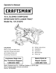
Operator's Manual
15Amp 3 HP (Max. Developed)
12" Blade
4200 R.P.M.
SLIDING COMPOUND
MITER SAW
With Laser
Model 137.212060
e
CAUTION:
e
Safety Instructions
Installation
Before using this Sliding Miter Saw,
read this manual and follow
e
e
Operation
Maintenance
all its Safety Rules and
e
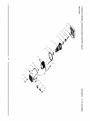
Parts List
Operating Instructions
Customer
Help Line
1-800-843-1682
Sears, Roebuck and Co., Hoffman Estates, IL 60179 U.S.A.
Visit our Craftsman website: www.sears.com/craltsman
Pan No.:137212060001
SECTION
PAGE
Warranty ........................................
Product Specifications .......................
Power Tool Safety ............................
Compound Miter Saw Safety ...............
Electrical Requirements and Safety ......
Accessories and Attachments ..............
SECTION
2
2
3
4
4-5
6
Tools Needed For Assembly ................
Carton Contents ..............................
PAGE
Know Your Sliding Miter Saw ..............
8
Glossary of Terms ............................
9
Assembly ......................................
10
Adjustments ....................................
11
Operation .......................................
17
Maintenance ...................................
26
6
7
TroubleshooIJng
Guide .......................
27
Parts List .........................................
28
FULL ON E YEAR WARRANTY
If this tool fails due to a defect in material or workmanship within one year of date of purchase, Sears will
at its option repair or replace it free of charge.
Return this tool to a Sears
This warranty
state to state.
gives
you
Sears,
Service
specific
Roebuck
Center
legal
and
for repair,
rights,
Co.,
and
Dept.
or to place of purchase
you
may also
817 WA,
have
Hoffman
for replacement.
other
Estates,
rights
which
may ,vary from
IL 60179
Some dust created I_y power sanding, sawing, grinding, drilling and other construction activities contains chemicals known
(to the State of California) to cause cancer, birl_ defects or other reproductive harm. Some examples of these chemicals
are:
Lead from lead-based paints
• Crystalline silica from bricks, cement and other masonry products
• Arsenic and chromium from chemically treated lumber
Your risk from these exposures varies, depending on how often you do this type of work. To reduce your e:_posure to
these chemicals, work in a well ventilated area and work with approved safety equipment such as dust masks that are
specially designed to filter out microscopic particles.
MOTOR
Power Source.....................
Horsepower........................
Speed.................................
Brake .................................
D_bte Insulated....................
lvlotorArbor Shaft Size .........
MITER
120 VAC, 60HZ, 15Amp
3PP (Max. Developed)
4200 I_M ('Noload)
Electric
Yes
5_"
SAW
Cutting
Capacity:
Crosscut
..............................
4" x 12-1/#'
Mter 45°R,&L ;.60°F_.......... 4"× 6-1/4"R&L;4"
× 8-3/4"R
Bevel45° R & L ......................
2-1/2"×12-1/4"LI 1-3/4"x12-I/4" R
45°tvlter
and45°BeveiR&L ...
2-1/2" × 8-3/4"
60°Mter and45°BeveiR ........ 3/4" x 6.-1/4"
BLADE SIZE
Diameter..............................
Arbor size ............................
Rotating Table:
Diameter..............................
12"
1" v/ a 5/8" reducer
Mter Detent Stops..................
13-W16"
0, 15, 22.5, 31.6, 45 °
RL&L. 60°R
Bevel Positiv_ Stops...............
Base Dimensions...................
0, 33.9, 45° R& L
23"x 16-3/4"
Extension Tak)le....................
Yes
66 Lbs
NetWeight ...........................
To avoid electrical hazards, fire hazards or damage to the tool, use proper circuit protection.
This tool is wired at the factory for 110-120 Volt operation. It must be connected to a 110-120 Volt / 15 Ampere time delay
fuse or circuit breaker. To avoid shock or fire, replace power cord immediately if it is worn, cut or damaged in any way.
Before using your tool, it is criticai that you read and understand these safety rules. Failure to follow these rules could
result in serious injury to you or damage to the tool.
GENERAL SAFETY INSTRUCTIONS
BEFORE USING THE SLIDING MITER SAW
Safety is a combination of commonsense, staying alert
and knowing how to use your sliding miter saw.
To avoid mistakes that could cause serious injury, do not
plug the tool in until you have read and understood the
following.
1. READ and become farniliarwith the entire Operators
Manual. LEARN the tool's application, limitations and
possible hazards.
2.
14.SECURE WORK. Use clamps or avise to hold work
when practical. It's safer t_an using your hand and it
frees both hands to operate tool.
15.DISCONNECT
TOOLS before the servicing, and
when changing accessories such as blades, bits and
cutters.
16.REDUCE THE RISK OF UNINTENTIONAL
STARTING. Make sure switch is in the OFF position
before plugging the tool in.
KEEP GUARDS IN PLACE and in working order.
3. REMOVE ADJUSTING KEYS AND WRENCHES.
Form the habit of checking to see that keys and
adjustingwrenches are removed from the tool before
turning ON.
4.
13.WEAR A FACE MASK OR DUST MASK. Sawing
operation produces dust.
KEEP WORK AREA CLEAN. Cluttered areas and
benches invite accidents.
5. DON'T USE IN DANGEROUS ENVIRONMENTS,
Don't use power tools in damp locations, or expose
them to rain or snow. Keep work area well lighted.
6. KEEP CHILDREN AWAY. All visitors and bystanders
should be kept a safe distance from work area.
7. MAKE WORKSHOP CHILD PROOF with padlocks,
master switches, or by removing starter keys.
8. DON'T FORCE THE TOOL. Itwill do the job better
and safer at the rate for which it was designed.
9. USE THE RIGHT TOOL. Do not force the tool or an
attachment to do a job for which it was not designed.
10. USE PROPER EXTENSION CORDS. Make sure
your extension cord is in good condition. When using
an extension cord, be sure to use one heavy enough
to carry the current your product will draw. An
undersized cord will result in a drop in line voltage
and in loss of power which will cause the tool to
overheat. The table on page 5 shows the correct size
to use depending on cord length and nameplate
ampere rating. If in doubt, use the next heavier gauge.
The smaller the gauge number, the heavier the cord.
11 .WEAR PROPER APPAREL. Do not wear loose
clothing, gloves, neckties, rings, bracelets, or other
jewelry which may get caught in moving parts.
Nonslip footwear is recommended. Wear protective
hair covering to contain long hair,
12.ALWAYS WEAR EYE PROTECTION. Any power tool
can throw foreign objects into the eyes and could
cause permanent eye damage.ALWAYS wear Safety
Goggles (not glasses) that comply with ANSI Safety
standard Z87.1 Everyday eyeglasses have only
impact-resistance lenses.
TheyARE NOT safety glasses, Safety
Goggles are available at Sears.
NOTE: Glasses or goggles not in
compliance with,Z_lSI Z87.1 could
seriously injure you when they break.
17.USE RECOMMENDED ACCESSORIES. Consult this
Operators Manual for recommended accessories.
The use of improperaccessories may cause risk of
injury to yourself or others.
18.NEVER STAND ON THE TOOL. Serious injury could
occur if the tool is tipped or if the cutting tool is
unintentionally contacted.
19.CHECK FOR DAMAGED PARTS. Before further use
of the tool, a guard or otherpartthat is damaged
should be carefullychecked to determinethat itwill
operate properlyand perform its intendedfunction check for alignmentof moving parts, bindingof
moving parts, breakageof parts,mounting, and any
other conditionsthat may affect itsoperation.A guard
or other partthat is damaged shouldbe properly
repaired or replaced.
20.NEVER LEAVE THE TOOL RUNNING UNATTENED.
TURN THE POWER "OFF". Don't walk away from a
running tool untilthe blade comes to a complete stop
& unplug the unit.
21 .DON'T OVERREACH.
balance at all times.
Keep proper footing and
22.MAINTAIN TOOLS WITH CARE. Keep tools sharp
and clean for best and safest performance. Follow
instructions for lubricating and changing accessories.
23.WARNING: Dust generated from certain materials
can be hazardous to your health. Always operate s_rw
in well-ventilated area and provide for proper dust
removal.
24.1MPORTAN'F: After completing a cut, release the
power switch and wait for the blade to stop before
returning the saw to the raised position.
Laser is acSvated when blade is rotating. Do not stare
into beam or view directly with optical instruments. Do
not remove the warning label affixed to the blade
guard. Avoid direct eye contact with light source.
i!!_i!!_i!!_i!!_i!!_i!!_i!!_i!!_i!!_i!!_i!!_i!!_i!!_i!!_i!!_i!!_i!!_i!!_i!!_i!!_
SPECIFICSAFETY INSTRUCTIONS
FOR
18. NEVER reach around the saw blade.
THIS SLIDING MITER SAW
19.MAKE SURE the blade is not contacting the
workpiece before the switch is turned ON.
The right side sliding fence must be removed when
making any right bevel angle cuts greater than 35 ° in
combination with any right hand miter angle.
This fence must also be removed whenever a 45 _'bevel
angle is desired with a miter angle greater than 22.5 °.
20.IMPORTANT:
After completing the cut, release the
power switch and wait for the blade to stop before
returning the saw to the raised position.
21.MAKE SURE the blade has come to a complete stop
before removing or securing the workpiece, changing
the workpiece angle, or changing the angle of the
blade.
1. USE ONLY CROSS-CUTTING
SAW BLADES. When
using carbide tipped blades, make sure they have a
nega_ve hook angle. IMPORTANT: DO NOT USE
THIN KERF BLADES- they can deflect and contact
guard and can cause possible injuryto the operator.
22.NEVER cut metals or masonry products with this tool.
This miter saw is designed for use on wood and
wood-like products.
2. DO NOT operate the miter saw until it is completely
assembled and installed according to these
instructions.
23.NEVER cut small pieces. If the workpiece being cut
would cause your hand or fingers to be within 8-3/4"
inches of the saw blade the workpiece is too small.
3. IF YOU ARE NOT thoroughly familiar with the
operation of miter saws, seek guidance from your
supervisor, instructor, or other qualified person.
24.PROVIDE adequate support to the sides of the saw
table for long work pieces.
25.NEVER use the miter saw in an area with flammable
liquids or gases,
4. ALWAYS hold the work firmly against the fence and
table. DO NOT perform any operation free hand (use
clamp wherever possible).
26.NEVER use solvents to clean plastic parts. Solvents
could possibly dissolve or otherwise damage the
material.
5. KEEP HANDS out of the path of the saw blade. If the
workpiece you are cut_ng would cause your hands to
be within 8-3/4" inches of the saw blade, the
workpiece should be clamped in place before making
the cut.
27.SHUT OFF the power before servicing or adjusting
the tool.
6. BE SURE the blade is sharp, runs freely, and is free
of vibration.
28.DISCONNECT
the saw from the power source and
clean the machine when finished using.
7. ALLOW the motor to come up to full speed before
starting a cut.
29.MAKE SURE the work area is clean before leaving
the machine.
8. KEEP THE MOTORAIR
chips or dust.
30.SHOULD any part of your miter saw be missing,
damaged, or fail in any way, or any electrical
component fail to perform properly, shut off the switch
and remove the plug from the power supply outlet.
Replace missing, damaged, or failed parts before
resuming operation.
SLOTS
CLEAN and free of
9. ALWAYS MAKE SURE all handles are tight and
locked in position before cutting. Lock the quick
cam miter lock for every cut even if the table is
positioned in one of the positive stops.
10.BE SURE both the blade and the collars are clean
and the arbor bolt is securely tightened.
11. USE only blade collars specified
ELECTRICAL
for your saw.
POWER
12. NEVER use blades larger or smaller in diameter
than 12-inches.
t5.
ALIi_AYS check the blade for cracks or damage
before operation. Replace a cracked or damaged
blade immediately.
NEVER use blades recommended
less than 4200 RPM
REQUIREMENTS
MOTOR
SPECIFICATIONS
The AC motor
used in this saw is a universal,
nonreversible type. See "MOTOR" in the "PRODUCT
SPECIFICATIONS"
section on page 2.
13. NEVER apply lubricants to the blade when it is
running.
t4.
SUPPLYAND
To avoid electrical hazards, fire hazards, or damage to
the tool, use proper circuit protection. Your saw is wired
at the factory for 120V operation. Connect to a 120V, 15
Amp circuit and use a 15 amp. time delay fuse or circuit
breaker. To avoid shock or fire, if power cord is worn or
cut,
or damaged
in any way,
have
it replaced
immediately.
for operation at
16. USE the blade guards at all times.
17. ALWAYS keep the blade guards in place.
4
DOUBLE
INSULATED
The power tool is double insulated to provide a double
thickness of insulation between you and tool's electrical
system. All exposed metal parts are isolated from the
internal metal motor components with protecting insulation.
4. FUSES may "blow" or circuit breakers may trip
frequently if:
a. MOTOR is overloaded - overloading can occur if
you feed too rapidly or make too many start/stops
in a short time.
b. LINE VOLTAGE is more than 10% above or below
Replacement parts - When servicing use only identical
replacement parts.
Polarized plugs - This saw has a plug that looks like bhe
one shown below:
the nameplate voltage rating. For heawt loads, the
voltage at motor terminals must equal the voltage
specified on the nameplate.
c. IMPROPER or dull saw blades are used.
5. Most motor troubles may be traced to loose or incorrect
connections, overload, low voltage or inadequate power
supply wiring. Always check the connections, the load
and supply circuit if the motor doesn't run well. Check
minimum gauge for the length of cord you are using on
the chart below.
GUIDELINES
To reduce the risk of electrical shock, this saw has a
polarized plug (one blade is wider than the other). This
plug will fit in a polarized outlet only one way. If the plug
does not fit fully in the outlet, reverse the plug. If it still
does not fit, contact a qualified electrician to install the
proper outlet. Do not change the plug in any way.
Double insulation does not take the place of normal safety
precautions when operating this tool.
To avoid electrocution:
1. Use only identical replacement parts when servicing a
tool with double insulation. Servicing should be performed
by a qualified technician.
2. Do not use power tools in wet or damp locations or
expose them to rain or snow.
This tool is intended for indoor use only.
MOTOR SAFETY PROTECTION
IMPORTANT:
To avoid motor damage, the motor should be blown out or
vacuumed frequently to keep sawdust from interfering with
the motor ventilation.
1. CONNECT this saw to a 120V, 15 amp. circuit with a 15
amp. time delay fuse or circuit breaker. Using the wrong
size fuse can damage the motor.
2. If the motor won't start, release the trigger switch
immediately. UNPLUG THE S/_v_. Check the saw blade
to make sure it turns freely. If the blade is free, tryto
start the saw again. If the motor still does not start, refer
to the "TROUBLESHOOTING
GUIDE"
3. IF the tool suddenly stalls while cutting wood, release
the trigger switch, unplug the tool, and free the blade
from the wood. The saw may now be started and the cut
finished.
FOR EXTENSION
CORDS
Use a proper extension cord. Make sure your extension
cord is in good condition. When using an extension cord,
be sure to use one heavy enough to carry the current your
product will draw. An undersized cord will cause a drop in
line voltage, resulting in loss of power and cause
overheating. The table below shows the correct size to use
depending on cord length and nameplate ampere rating. If
in doubt, use the next heavier gauge. The smaller the
gauge number, the heavier the cord.
Be sure your extension cord is properly wired and in
good condition. Always replace a damaged extension cord
or have it repaired by a qualified person before using it.
Protect your extension cords from sharp objects, excessive
heat and damp or wet areas.
Use a separate electrical circuit for your tools. This
circuit must not be less than # 12 wire and should be
protected with a 15 Amp time delay fuse. Before
connecting the tool to the power line, make sure the switch
is in the OFF position and the electric current is rated the
same as the current stamped on the motor nameplate,
running at a lower voltage will damage the motor.
(When using 120 volts only)
Ampere
Rating
if]ore th_n
not
Total length
of cord in feet
25'
50'
100'
150'
6
18
16
16
14
10
18
16
14
12
10
12
16
16
14
12
12
16
14
12
3
mofe
thZ_R
notrecommended
CAUTION: In all cases make certain the receptacle in
question is properly grounded. If you are not sure have a
certified electrician, check the receptacle.
RECOM MENDED ACCESSORIES
•
•
•
Use only accessories recommended for this miter saw.
Follow instructions that accompany accessories. Use
of improper accessories may cause hazards.
The use of any cutting tool except 12 inch saw blades
that meet the requirements under recommended
accessories is prohibited. Do not use accessories such
as shaper cutters or dado sets. Ferrous metal cutting,
the use of abrasive wheels and the cutting of masonry
products are prohibited.
Do not attempt to modify this tool or create
accessories not recommended for use with this tool.
Any such alteration or modification is misuse and could
result in a hazardous condition leading to possible
serious injury.
ACCESSORIES
Visit your Sears Hardware Depar_nent or see the Sears
Power and Hand Tool Catalog to purchase recommended
accessories for this power tool.
To avoid the risk of personal injury, do not modify this
power tool or use accessories not recommended by Sears.
Read warnings and conditions on your carbide tipped saw
blade. Do not operate the saw without the proper saw
blade guard in place. Carbide is avery hard but brittle
material. Care should be taken while mounting, using, and
storing carbide tipped blades to prevent accidental
damage. Slight shocks, such as striking the tip while
handling, can seriously damage the blade. Foreign objects
in the workpiece, such as wire or nails, can also cause tips
to crack or break off. Before using, always visually
examine the blade and tips for bent teeth, cracks,
breakage, missing or loose tips, or other damage. Do not
use if damage is suspected. Failure to heed to these safety
instructions and warnings can result in serious bodily
injury.
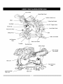
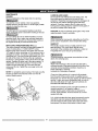
UNPACKING YOUR SLIDING MITER SAW
To avoid injury from unexpected starting or electrical
shock, do not plug the power cord into a source of power
during unpacking and assembly. This cord must remain
unplugged whenever you are working on the saw.
].
Remove the miter saw from the carton.
IMPORTANT: Do not lift the miter saw by the switch
handle or miter table handle. It may cause
misalignment. Lift the machine by the built in carry
handles.
2.
3,
Separate all parts from the packing material. Check
each one with the illustration to make certain all
items are accounted
packing material.
for, before discarding any
If any part is missing or damaged, do not attempt to
assemble the miter saw, or plug in the power cord until
the missing or damaged part is correctly replaced. To
avoid electric shock, use only identical replacement parts
when servicing double insulated tools.
Place the saw on a secure stationary work surface.
Blade Wrench
Dust Bag
Power Cord _orage
Mounting Hardware
Power Cord
Storage Clips
Hold-down Clamp
Hold -down Clamp
Lock Knob
Miter Saw
Clip
Carry Handle
Upper Blade Guard
Handle Locking Lever
Motor
Cutting Head Handle
Saw Blade
ON / OFF Trigger Switch
Bevel Scale
Lower Blade Guard
Hold Down Clamp
Sliding Fence
Base
Miter Lock Handle
Left Extension
Table
Turntable
f
Bevel Lock Handle
Mounting Holes
Slide Carriage
Slide Carriage
Lock Handle
Belt cover
Right Extension
Table
Quick-Cam Miter
Table Lock
Table insert
CRAFTSMAN
SAW TERMS
SLIDING
COMPOUND
MITER
ARBOR LOCK - Allows the user to keep the blade from
rotating while tightening or loosening the arbor Ioct_ng bolt
during blade replacement or removal.
BASE - Supports the table, holds accessories
for workbench or leg set mounting.
BEVEL
LOCKING
HANDLE
-
and allows
Locks the miter
WRENCH
STORAGE
- Convenient
misplacing the blade wrench.
BEVEL SCALE - To measure
blade 0° to 45 ° left and right.
PLATE
SCREW
WOODWORKING
ARBOR-
TABLE - Extends
the width of the work table
for support while cutting long work pieces. Each extension
table incorporates a stop lever for repetitive cuts.
FENCE - Helps to keep the workpiece from moving when
sawing. Scaled to assistwithaccurate cuing.
RETRACTABLE
LOWER BLADE GUARD - Helps protect
your hands from the blade in the raised position, it retracts
as the blade is lowered.
MITER HANDLE - Used to rotate the saw to the right or
left cuttingposition.
MITER SCALE - Measures the miter angle of the saw
blade. Positive stop index points have been provided at 0's,
15 °, 22.5 °, 31.6 _'and 45 ° right and left, and 60 ° right.
SPRING
LOCK
-
Used
in combination
with the
miter handle, it locks the miter saw at a preset positive stop
for the desired miter angle.
MOUNTING
surface.
HOLES
to prevent
TERMS
- Loosen this screw and rotate
DUST CHUTE - Exhausts debris away from the user.
MITER
storage
the bevel angle of the saw
the plate for access to the blade arbor Iocl_ng bolt.
EXTENSION
WARNING LABELS - Read and understand for your own
safety. Always make certain these are in place & legible.
saw at a
desired bevel angle.
COVER
SWITCH HANDLE - The cutting head handle contains the
1rigger switch and a safety lock-off slide switch. The blade
is lowered into the workpiece by pushing down on the
handle. The saw will return to its upright position when the
handle is released.
- To mount the miter saw to a stable
ON/OFF TRIGGER SWITCH - To prevent the trigger from
being accidentally engaged,
a lock-off slide switch is
provided. To start the tool, push the lock-off slide switch
forward and squeeze the trigger. Release the trigger to
stop the miter saw.
STOP LATCH - Locks the miter saw in the lowered
position for compact storage and transportation.
The shaft on which a blade is mounted.
BEVEL CUT - An angle cut made through
workpiece.
COMPOUND
CROSS CUTworkpiece.
CUT -A simultaneous
the face of the
bevel and miter cut.
A cut made across the width or grain of the
FREEHAND
- Performing
a cut without using a fence
(guide), hold down or other proper device to prevent the
w_rkpiece from twisting during the cutting operation.
GUM-A
sticky sap from wood products.
HEEL - Misalignment of the blade.
KERF - The amount of material removed by blade cut.
MITER CUT- An angle cut made across the width or grain
of the workpiece.
RESIN -A sticky sap that has hardened.
REVOLUTIONS PER MINUTE (RPM) - The number of
turns completed by a spinningobject in one minute.
SAW BLADE PATH - The area of the workpiece or table
top directly in line with the travel of the blade or the part of
the workpiece which will be cut.
SET - The distance between two saw blade tips, bent
outward in opposite directions to each other. The further
apart the tips are, the greater the set.
WORKPIECE
- The item being cut. The surfaces of a
workpiece are commonly referred to as faces, ends, and
edges.
ASSEM BLY INSTRUCTIONS
Fig. B
To avoid injury, do not connect this miter saw to the
power source until it is completely assembled and
adjusted, and you have read and understood this
Operators Manual.
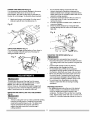
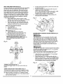
UNLOCKING THE SLIDE CARRIAGE (Fig, A)
Afl_r removing the saw from the carton, loosen the
slide carriage lock knob. When transporting or storing
the miter saw, the slide carriage should always be
locked in position. The carriage lock handle (1) is
located on the right side of the slide carriage.
4
/
Fig. A
INSTALLING THE DUST BAG (Fig. C)
1. To install the dust bag (1), squeeze the metal collar
wings (2) and place the dust bag neck opening
around the exhaust port (3), and release the metal
collar wings.
Fig. C
\
LOCK THE CUTTING
\
HEAD (Fig. B)
To avoid injury and damage to the saw, transport or
store the miter saw with the cutting head in the down
position. NEVER use the lock pin to hold the cutting
head in a down position for cutting operations.
To unlock the cutting head from the collapsed position:
1. Push down slightly on the cutting head (2).
2. Pull outthelockpin
(3).
3. Allow the cutting head to rise to the uppermost
position.
When transporting
or storing the miter saw, the cutting
head should always be locked in the down position:
1. Push the cutting head (2) down to the collapsed
position.
2. Push the lock pin (3) into the locking hole (4).
IMPORTANT: To avoid damage, never carry the miter
saw by the switch handle, the cutting arm, or the miter
table handle. ALWAYS use the designated carrying
handles located on the top of the machine.
INSTALLING
THE SAFETY
HOLD-DOWN
CLAMP
(Fig. D)
1. Insert one safety hold-down clamp lock knob (1)
into the rear of the base of the machine for each
side.
2.
Place the Safety hold-down Clamp (2) into the
mounting hole.
Fig. D
POWER CORD BRACKETS (Fig. E)
For convenience and to prevent damage to the power
cord when the miter saw is not in use or is in
•
transportation, the slide carriage has two brackets on
the rear for cord storage. To assembly these brackets:
1.
1. Attach each power cord bracket (2) to the rear of
slide-bar seat with one mounting screw (1),
2.
Fig. E
3.
Do not start the sliding compound miter saw
without checking for interference between the
blade and table insert. Damage could result to the
blade, table insert or turntable if blade strike occurs
during the cutting operation.
To remove, loosen and remove the six screws (1)
on the table insert (2) with a screwdriver and
remove the insert.
To install, reposition the table insert, install the six
screws and tighten.
Check for blade clearance by moving the slide
carriage through the full motion of the blade in the
table slot.
Fig. H
mi
S,_IN BLADE WRENCH (Fig. F)
For convenient storage and prevention of loss, there is
a slot (1) located atthe left rear foot of the base for
storing the blade wrench (2).
2
MOUNTING THE MITER S/_f (Fig. I,J)
Fig. F
To avoid injury disconnect the plug from the power
source before performing any adjustments or repair.
NOTE: Your miter saw was adjusted at the
factory. However, during shipment slight misalignment
may have occurred. Check the following settings and
adjust if necessary prior to using this miter saw.
REMOVINGAND INSTALLING THE TABLE INSERT
(Fig. H)
To avoid injury form unexpected saw movement:
• Disconnect the power cord from the outlet, and lock
the cutting head in the lower position using the lock
pin.
° Lockthe slide carriage in place in place by
tightening the slide carriage lock knob.
° To avoid back injury, lift the saw by using the
designated carrying handles located on the top of
the machine. Bend with your knees, not your back.
• Never carry the miter saw by the power cord or by
the switch handle. Carrying the tool by the power
cord could cause damage to the insulation or the
wire connections resulting in elecb'ic shock or fire.
• To avoid injury from flying debris, do not allow
visitors to stand near the saw during all cuing
operations.
Mounting instructions
1. For stationary use, place the saw in the desired
location, directly on a workbench where there is
room for handling and proper support of the
workpiece. The base of the saw has four mounting
holes. Bolt the base of the miter saw (1) to the work
surface (5), using the fastening method as shctwn in
To avoid injury:
•
Always unplug the saw to avoid accidental starting.
Remove all small pieces of material from the table
cavity before performing any cuts. The table insert
may be removed for this purpose, but always
reattach the table insert prior to performing a
cutting operation.
]:t
5. Rotate the cover plate (3) to expose the arbor bolt
Fig. I
1.
2.
4.
5.
7.
9.
Miter saw base
Hex head bolt
Rubber washer
Flat washer
Workbench
Flat washer
Lock"washer
Hex nut
Jam nut
(4).
6. Place the blade end wrench over the arbor bolt.
S
._
I
I
I
I
Fig. K
Ii
NOTE: Mounting hardware is not included with this
tool. Bolts nuts, washers, & screws must be
purchased separately.
1.
1
2
For portable use, place the saw on a 3/4" thick
piece of plywood. Bolt the base of the miter saw
securely to the plywood using the mounting holes
on the base. Use C-clamps to clamp this mounting
board to a stable work surface at the worksite. (Fig,
/*
/
/
J)
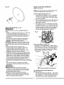
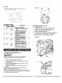
7. Locate the arbor lock (5) on the motor, below the belt
cover. (Fig. L)
8. Press the arbor lock, holding it in firmly while turning
the blade clockwise. The arbor lock will then engage
and lock the arbor. Continue to hold the arbor lock,
while turning the vcrench clockwise to loosen the
arbor bolt.
Fig. J
i
REMOVING
OR INSTALLING
THE BLADE
Only use a 12-inch diameter blade.
To avoid injury from an accidental start, make sure
the switch is in the OFF position and plug is not
connected to the power source outlet.
REMOVING (Fig. K, L, lVl)
1. Unplug the saw from the outlet
2. Raise the miter saw to the upright position.
3. Raise the lower clear plastic blade guard (!) to the
uppermost position. (Fig, K)
4. While holding the lower blade guard, loosen the
cover plate screw (2) with a Phillips screwdriver.
9.
Remove the arbor bolt, the laser collar (6), and the
blade (7). Do not remove the inner blade collar.
(Fig. IV])
10. Raise the lower clear plastic blade guard (1) to the
upright position (Fig. K) to remove the blade.
NOTE: Pay attention to the pieces removed, noting
their position and direction they face. Wipe the blade
collars clean of any sawdust before installing a new
blade. Also, the 12" blade has a 1" arbor hole with a
5/8" reducer to mount onto the saw.
Fig. M
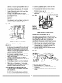
BEVEL STOP ADJUSTM
(Fig. N, N-l, N-2, O)
ENTS
NOTE: To ensure accurate cuts, alignment should be
checked and adjustments made prior to use.
0 ° Bevel adjustment (Fig N, N-2, O)
1, Loosen bevel lock handle (4- Fig. O) and tilt the
cutting arm while pushing in the bevel detent pin
(1 - Fig. N-21 in against the 0° bevel stop. Tighten
the bevel lock handle.
2.
6
4
7
INSTALLING BLADE (Fig. K, L, M)
Un-plug the miter saw before changing/installing the
blade,
1. Install a 12" blade with a 5f8" arbor (or a 1" arbor with
a 5/8" reducer) making sure the rotation arrow
on the blade matches the clockwise rotation arrow on
3,
Place a combination square on the miter table with
the rule against the table and heel of the square
against the saw blade.
If the blade is not 0° to the miter table, loosen the
four adjustment bolts (1 - Fig. N) at the rear of the
unit with a 5 mm hex wrench. Unlock the bevel lock
handle and adjust the cutting arm zero degrees to
the table. Tighten the bevel lock handle and the
four he× bolts after alignment is achieved.
Fig. N
the upper guard, and the blade teeth are pointing
downward.
2. Place the laser collar (4) against the blade and on
the arbor. Thread the arbor bolt (6) on the arbor.
(Fig. M) in a counterclockwise direction.
IMPORTANT: Make sure the flats of the blade collars
are engaged with the fiats on the arbor shaft. Also, the
flat-side of the laser collar must be placed against the
blade.
3. Place the blade wrench on the arbor bolt.
4. Press the arbor lock (5t, holding it in firmly while
turning the blade counterclockwise. When
it
engages, continue to press the arbor lock in, while
tightening the arbor bolt securely, (Fig. L)
5. Rotate the cover plate (3) backto its original position
until the slot in the cover plate engages with the cover
plate screw (21. While holding the lower blade guard,
tighten the screw with a Phillips screwdriver. (Fig. L)
NOTE: The lower blade guard must be raised to the
upright position to access the cover plate screw.
6. Lower the clear retractable blade guard (1) and verify
the operation of the guard does not bind or stick. (Fig.
K)
Bevel Scale Indicators (Fig. N-l)
1. When the 0° bevel adjustment is complete, adjust
both indicators (2) so the tip of the pointers align with
the 0° line on the bevel scale (3) by loosening the
pointer screw (11 using a screwdriver then retighten
the screw after adjustment is complete.
Fig. N-1
2
7
7. Be sure the arbor lock is released so the blade
turns freely by spinning the blade until the arbor lock
disengages,
• Make sure the collars are clean and properly
arranged. Lower the blade into the lower table and
check for any contact with the base or the turn table
by spinning the blade manually.
• Make sure the collars are clean and properly
arranged. Lover the blade into the lower table and
check for any contact with the metal base or the turn
table by spinning the blade manually.
3
6
5
NOTE: View from left front of machine
45 ° Left Bevel Positive Stop Adjustment
(Fig. N-l, N-2, O)
1. Set the miter angle to zero degrees.
Fully extend
the sliding fence completely to the left then pull the
bevel detent pin (1 - Fig. N-2 t toward the front of
the machine, NOTE: When retracting the bevel
2.
3.
4.
5.
6.
detent pin, it may be required to shift the miter saw
upper arm assembly to the left/right.
Loosen the bevel lock handle (4- Fig. O) and tilt
the cutting arm completely to the left.
Using a combination square, check to see if the
blade is 45 ° to the table.
To adjust, tilt the cutting arm to zero degrees,
loosen the Iocknut (5) and turn the bolt (6) in or out
accordingly. (Fig. N-l)
Tiltthe cutting arm backto the left and recheck
alignment.
Repeat steps until the blade is 45 ° to the table.
Once alignment is achieved, tighten the Iocknut (5)
to secure the positive stop bolt. (Fig. N-l)
3.
Using a combination square, check to see if the
blade is 33.9 ° to the table.
4.
To adjust, turn the screw in or out with a wrench
(from the locations shown below) until the blade is
33.9 ° to the table. (Fig. N3)
Repeat steps for the right bevel 33.9 ° bevel
5.
adjustment.
For }3.9_1_ b_,'elpc_itivestop
adju_ment,insert wrench
here
Fig. N-3
Fig. N-2
For 33.9_
left beve!
positive s_op
adjL_trnent,
insert _ranch here
NOTE: View from rear of machine
6
MITERANGLE ADJUSTMENT (Fig. O)
5
NOTE: View from rear of machine
45 ° Right Bevel Positive Stop Adjustment
(Fig. N-2, O)
1. Set the miter angle to zero degrees,
Fully extend
the sliding fence completely to the right then pull
the bevel detent pin (1 - Fig. N-2) toward the front
of the machine. NOTE: When re_acting the bevel
detent pin, it may be required to shift the miter saw
upper arm assembly to the left/right.
2. Loosen the bevel lock handle (4 - Fig. O) and tilt
the cutting arm completely to the right.
3. Using a combination square, check to see if the
blade is 45 ° to the table.
4. To adjust, tiltthe cutting arm to zero degrees,
loosen the Iocknut (5) and turn the bolt (6) in or out
accordingly, (Fig, N-2)
5. Tilt the cutting arm back to the right and recheck
alignment.
6. Repeat steps until the blade is 45" to the table,
Once alignment is achieved, tighten the Iocknut (5)
to secure the positive stop bolt. (Fig, N-2)
33.9 ° Left & Right Bevel adjustment (Fig. N-3)
1. Set the miter angle to zero degrees. Fully extend
both sliding fences.
2. Loosen the bevel lock handle and tilt cutting arm to
the 33.9 ° left bevel positive stop by pushing in on
the bevel detent pin toward the rear of the machine.
The sliding compound miter saw scale can be easily
read showing miter angles from 0° to 45 ° to the left, and
0 ° to 60 ° to the right. The most common angle cut
setting slots have positive stops, permitting fast
adjustments to the desired position. Follow the process
below for quickest and most accurate adjustments.
1. Lift up on the miter quick lock to unlock the table.
2. Move the turntable while lifting up on the positive
stop locking lever (1) to align the indicator (2) to
the desired degree measurement.
4.
Lock the table into position by pressing down on
the miter quick lock.
Fig. O
3
2
Miter Scale indicator (Fig. O)
1, Move the table to the 0 ° positive stop.
2. Loosen the screw (3) that holds the indicator with a
screwdriver,
3, Adjust the indicator (21)to the 0 ° mark and retighten
screw.
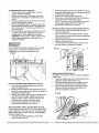
To Square Blade to Fence (Fig. P):
1. Turn the upper arm assemblyto the 0 ° bevel
position and lock in position.
2. Using a hex keywrench, loosen the four fence
locking hex socket bolts (1) untilthe fence (2) is
loose.
3. Lower the cutting head assembly and lock it in the
down position with the stop pin.
4. Using a combination square (3), lay the heel of the
square against the blade, and the rule against the
fence (2) as shown. Check to see if the fence is
90 ° to the blade.
5. If an adjustment is necessary, shift the fence until it
is square to the blade. _ghten the four fence
locking bolts (1) once alignment is achieved.
CAUTION: If the saw has not been used recently,
recheck blade squareness to the fence and
readjust if needed.
2.
3.
4.
While holding the positive stop locking lever up (2),
grasp the miter handle and move the miter table left
or right to the desired angle.
Release the positive stop locking lever..
Press down on the Miter Quick-Cam locking lever
(3) until it locks the miter table in place.
NOTE: The miter Quick-Cam locking lever should
lock the table and prevent it from moving. If
adjustment is needed, see next step.
Quick-Cam Miter Table Lock Adjustment: (Fig. Q)
1. Press down and lock the Quick-cam the miter
2.
3.
4.
To avoid injury:
Form unexpected starting or electrical shock, do not
plug the saw in. The power cord MUST remain
unplugged when you are working on the saw.
quick-cam table lock.
Turn the stop nut (5) to the left as shown using a
13ram wrench to extend the locking arm against the
base of the miter saw.
Test the quick cam miter lock to verify it locks the
table into position securely.
Turn the lock nut (6) to the right as shown to lock
the miter locking mechanism into place.
Fig. Q
Fig. P
5
4
1
2
Setting Cutting Depth (Fig. R)
The depth of cut can be preset for even and repetitive
shallow cuts.
1.
2.
Positive Stop Miter Angle Adjustment: (Fig. Q)
1. Unlock the miter table by lifting up on the miter
quick-cam table lock (3).
2. While raising the positive stop locking lever up (2),
grasp the miter handle and rotate the miter table left
or right to the desired angle.
3. Release the positive stop locking lever and set the
miter at the desired angle making sure the lever
snaps into place. NOTE: The lever will only lock
into place at one of the ten positive stops.
4. Once angle is achieved, press down on the
quick-cam miter table lock (3- Fig. (3).
Quick-Cam Miter Table Lock Operation: (Fig. Q)
If miter angles required are NOT one of the ten positive
stops noted above, the mitertable can be locked at any
angle between these positive stops I_y using the Miter
Quick-Cam table lock.
1.
Unlock the miter table by lifting up on the miter
quick-cam table lock (3).
3.
Adjustthe cutting head down until the teeth of the
blade are at the desired depth of cut.
While holding the upper arm in position, turn the
stop knob (1) until it touches the stop plate (2).
Recheck the blade depth by moving the cutting
head front to back through the full motion of a
typical cut along the conb'ol arm.
Fig. R
Maximum Cut'dng Depth (Fig. R)
The maximum depth trawl of the cutting head was set
at the factory, Check to see that the cutting head does
not extend more than 1/4" belowthe table insert, and
does not touch the control arm throat or any part of the
base or table. If the maximum depth needs readjusting:
1. Loosen the bolts ofthe stop plate (2).
2.
Move the cutting head down until the blade extends
just 1/4" below the table insert.
3. Adjust the stop place to touch the bottom of the
stop knob (1) when the stop knob is raised fully.
4.
Recheck the blade depth by moving the cutting
head fTont to back through the full motion of a cut
along the control arm. If the blade touches the
inside of the control arm, readjust the setting.
THE LASER -TRAC_
Your tool is equipped with our latest innovation, the
Laser -Trac _, a battery powered device using Class
]]_a laser beams, The laser beams will enable you
to preview the miter blade pa_ on the workpiece to
be cut before you begin your operation.
Laser is activated when blade is rotating. Do not stare
into beam or view directly with optical instruments. Do
not remove the warning label affixed to the blade
guard. Avoid direct eye contact with light source.
NOTE - The red laser line will appear as a dotted line
when the motor is activated and the blade assembly is
in the uppermost position. This broken line will assist
you in aligning the mark on your workpiece with the
cutting path of the saw blade. As you lower the blade
assembly, the retractable guard will lit_ and turn the
broken line into a solid red laser line.
Laser Warning label: Max output <5row DIODE LASER:
630-670nm, Complies with 21CFR 1040.10 and 1040.
11.
OPERATION OF LASER
With the blade assembly in the uppermost position:
1. Position your workpiece onto the miter saw.
2. Turn on the miter saw to activate the laser beam.
3.
4.
5.
6.
Verify the laser beam is aligned with the mark on
the workpiece (WARNING - Do not lower the blade
assembly during the alignment process).
If the mark on the workpiece is not aligned with the
dotted laser line, tum off machine, wait for the
blade to stop and reposition workpiece.
Turn on the miter saw and verify alignment.
Once alignment is achieved, secure workpiece with
a clamping device and perform the cut.
SAFETY INSTRUCTIONS
OPERATION
FOR BASIC SAW
•
BEFORE USING THE MITER SAW
To avoid mistakes that could cause serious, permanent
injury, do not plug the tool in until the following steps are
completed:
•
Completely assemble and adjust the saw, following
the instructions. (ASSEMBLY AND ADJUSTMENTS)
•
Learn the use and function of the ON/OFF switch,
lock-off switch, upper and lower blade guards, stop
latch, bevel lock handle, and cover plate screws.
•
Review and understand all safety instructions and
operating procedures in this Operator's Manual.
(SAFETY & OPERATIONS)
•
Review the MAINTENANCE and
TROUBLI :SHOOTING GUIDE for your miter saw.
•
To avoid injury or possible death from electrical shock:
Make sure your fingers do not touch the plug's metal
prongs when plugging or unplugging your miter saw.
(ELECTRICAL REQUIREMENTS
AND SAFETY)
•
•
USE ONLY RECOMMENDED
ACCESSORIES
•
Consult the ACCESSORIES
and ATTACHMENTS
section of this Operators Manual for recommended
accessories. Follow the insb'uctions that come with
the accessory. The use of improper accessories may
cause risk of injury to persons.
•
The right side sliding fence must be removed when making
any right bevel angle cuts greater than 35 ° in combination
with any right hand miter angle.
This fence must also be removed whenever a 45 ° bevel
angle is desired with a miter angle greater than 22.5 °.
Laser is activated when blade is rotating. Do not stare into
beam or view directly with optical instruments. Do not
remove the warning label affixed to the blade guard. Avoid
direct eye contact with light source.
BEFORE EACH USE
Inspect your saw.
•
Disconnect the miter saw. To avoid injury from
accidental starting, unplugthe saw before any
adjustments,includingset-up and blade changes.
•
Compare the direction of rotation arrow on the
guardto the directionarrow on the blade. The blade
teeth should alwayspoint downwardat the front of the
saw.
•
Tighten the arbor holt.
•
Tighten the cover plate screw.
•
Check for damaged parts. Check for:
•
Alignment of moving parts
•
Damaged electric cords
•
Binding of moving parts
•
Mounting holes
•
Function of arm return spring and lower guard:
Push the cutting arm all the way down, then let it
rise until it stops. The lower guard should fully
close. Follow instructions in
TROUBLESHOOTING GUIDE for adjustment.
• Other conditions that may affect the waythe miter
saw works.
Keep all guards in place, in working order and proper
adjustment.
If any part of this miter saw is missing, bent damaged
or broken in any way, or any electrical parts don't work,
turn the saw off and unplug it.
Replace damaged, missing, or defective parts before
using the saw again.
Maintain tools with care. Keep the miter saw clean for
best and safest performance. Follow ins_'uctions for
lubricating. Don't put lubricants on the blade while it's
spinning.
Remove all adjusting wrenches from the tool before
turning it on.
Choose the correct 12 inches diameter blade for the
material and the type of cut'dngyou plan to do. Do not
use Thin Kerfblades.
Make sure the blade is sharp, undamaged and
properly aligned. With the saw unplugged, push the
cutting arm all the way down. Manually spin the blade
and check for clearance. Tilt the miter-head to a 45 °
bevel and repeat the test.
•
Make sure the blade and arbor collars are clean.
•
Make sure all clamps and locks are _ght and there is
no excessive play in any parts.
KEEP YOUR WORK AREA CLEAN
Cluttered areas and benches invite accidents.
To avoid burns or other fire damage, never use the miter
saw near flammable liquids, vapors, or gases.
•
Plan ahead to protect your eyes, hands, face and
ears.
•
Knowyour
miter saw.
Read and understand the Operator's Manual and labels
affixed to the tool. Learn its application and limitations as
well as the specific potential hazards peculiar to this tool.
To avoid injury from accidental contact with moving parts,
don't do layout, assembly, or setup work on the miter saw.
•
Avoid accidental starting
Make sure the switch is OFF before plugging the
miter saw into a power outlet.
PLANYOURWORK
Use the right tool. Don't force a tool or attachment to
do a job itwas not designed to do. Use a different tool
for any workpiece that can't be held in a solidly braced,
fixed position.
CAUTION: This machine is NOT designed for cutting
masonry, masonry products & ferrous metals (steel, iron,
and iron-based metals.) Use this miter saw to cut only
wood & wood-like products. Other material may shatter,
bind the blade, or create other dangers. Remove all nails
that may be in the workpiece to prevent sparking that could
cause a fire.
DRESS FOR,_FETY
Any power tool can throw foreign objects into the eyes.
This can result in permanent eye damage. Everyday
eyeglasses have only impact resistant lenses and are not
safety glasses. Glasses or goggles not in compliance with
ANSI Z87.1 could seriously injure you when they break.
•
Do not wear loose clothing, gloves, neckties or jewelry
(rings, watches). They can get caught and draw you
into moving parts.
•
Wear non-slip footwear.
•
l]e back long hair.
•
Roll long sleeves above the elbow.
•
Noise levels vary widely. To avoid possible hearing
damage, wear ear plugs when using any miter s_rw.
•
For dusty operations, wear a dust mask along with
safety goggles.
INSPECT YOUR WORKPIECE
Make sure there are no nails or foreign objects in the part
of the workpiece being cut.
Plan your work to avoid small pieces that may bind, or
that are too small to clamp and get a solid grasp on.
Plan the way you will grasp the workpiece from start to
finish. Avoid awkward operations and hand positions.
A
sudden slip could cause your fingers or hand to move into
the blade.
•
Make sure there are no gaps between the workpiece,
fence and table that will let the workpiece shitt during
the cut.
•
Keep the cut off piece free to move sideways after it is
cut off. OthenMse, it could get wedged against the
blade and thrown, possibly causing injury.
Only the workpiece should be on the saw table.
Secure work. Use clamps or a vise to help hold the
work when it's prac_cal.
•
•
USE EXTRA CAUTION WITH LARGE OR ODD SHAPED
WORKPIECE8.
•
•
•
•
•
Use extra supports (tables, sawhorses, blocks, etc.)
for workpieces large enough to tip.
Never use another person as a substitute for a table
extension, or as an additional support for a workpiece
that is longer or wider than the basic miter saw table,
or to help feed, support, or pull the workpiece.
Do not use this saw to cut small pieces. If the
workpiece being cut would cause your hand or fingers
to be within 8-3/4" inches of the saw blade workpiece
is too small. Keep hands and fingers out of the "no
hands zone" area marked on the saws table.
When cutting odd shaped workpieces, plan your work
so it will not bind in the blade and cause possible
injury. Molding, for example, must lie fiat or be held by
a fixture or jig that will not let it move when cut.
Properly support round material such as dowel rods,
or tubing, which have atendencyto
roll when cut,
causing the blade to "bite".
To avoid injury, follow all applicable safety instructions,
when cutting non-ferrous metals:
•
Use only saw blades specifically recommended for
non-ferrous metal cutting.
•
Do not cut metal workpieces that must be hand held.
Clamp workpieces securely.
•
Cut non-ferrous metals only if you are under the
supervision of an experienced person.
WHEN SAW IS RUNNING
DON'T OVER-REACH
Keep good footing and balance. Keep your face and body
to one side, out ofthe line of a possible kickback.
NEVER
stand in the line of the blade.
Never cut freehand:
•
Brace your workpiece firmly against the fence and
table stop so it will not rock or twist during the cut.
•
Make sure there is no debris between the workpiece
and the table or fence.
Don't allow familiarity from frequent use of your miter saw
to result in a careless mistake. A careless fraction of a
second is enough to cause a severe injury.
Before cutting, if the saw makes an unfamiliar noise or
vibrates, stop immediately. Turn the saw OFF. Unplug the
saw. Do not restart until finding and correcting the problem.
BODYAND HAND POSITION (Fig. S)
Proper positioning of your body and hands when operating
the miter saw will make cutting easier and safer. Never
place hands near the cutting area. Place hands at least
8-3/4" away from the path of the blade. Hold workpiece
firmly against the fence to prevent movement toward the
blade. Keep hands in position until the trigger has been
released and the blade has completely stopped. Before
making a cut, with the power switch in the OFF position
bring the saw blade dov_ to the workpiece to see the
cutting path of the blade.
*
Keep children away. Keep all visitors a safe
distance from the miter saw. Make sure bystanders
are clear of the miter saw and workpiece.
•
Don't force the tool. It will do the job better and
safer at its designed rate. Feed the saw into the
workpiece slowly with a firm downward motion.
2.
Pull the handle-locking latch (3) to the front of the saw
and hold in position.
Rotate the handle to the desired positive stop and
release the handle locking latch.
NOTE: After releasing the handle locking latch, rotate
the handle left and right to make sure the latch
engages into the positive locking position.
Lock the handle locking lever (2) by pushing it IN
toward the rear of the handle.
3.
4.
Fig, T
2
Before freeing jammed material.
•
Turn switchOFF.
•
Unplug the miter saw,
•
Wait for all moving parts to stop.
Alter finishing a cut.
•
Keep holding the power head down.
•
Release the switch, and wait for all moving
parts to stop before moving your hands.
•
If the blade doesn't stop within 6 seconds,
unplug the saw and follow the instructions in
THE TROUBLESHOOTING
GUIDE section for
adjusting the blade brake before using the
saw again.
Fig. S
SLIDING FENCE & REMOVE SLIDING FENCE (Fig. U)
Sliding Fence
The sliding fence must be extended to the left or right
when making bevel cuts. The sliding fences note three
bevel angles where the user must adjust the fences to
match the degree of the bevel cut. Failure to extend the
sliding fence will not allow enough space for the blade to
pass through which could result in serious injury. At
ex_eme miter or bevel angles the saw blade may also
contact the fence.
The right side sliding fence must be removed when making
any right bevel angle cuts greater than 35 ° in combination
with any right hand miter angle.
This fence must also be removed whenever a 45 ° bevel
angle is desired with a miter angle greater than 22.5 °.
Unlock the fence cam locking lever (1) by pushing it
toward the rear of the machine.
E_end the fence (2) by sliding it out to match the
degree of the bevel cut. Lock the fence cam locking
lever by pushing it IN toward the fence. NOTE: When
transporting the saw, always secure the sliding fence
in the collapsed position (toward the saw blade).
l,
2.
/--,, l-<
!_7%'1.t
_)"
_t .Y !.,
\_ ,
J
8-3/4"
8-3/4"
TURNING THE SAW ON (Fig. "r)
Depress the trigger switch (1) to turn on the miter saw.
started.
THREE POSITION ROTATING HANDLE (Fig. 1")
The handle of the miter saw has been designed to rotate
and lock at three different positive stops; 45 ° left, 0 °, and
45 ° right for operator convenience. To rotate the handle:
1. Unlock the handle locking lever (2) by pulling it toward
the front of the machine.
1
2
Removing or Installing the Right Sliding Fence
Removing (Fig. U-l)
1. Unlockthe fence cam-lockinglever by pushingit out
towardthe rear of the machine.
2. Liftup on the slidingfence to remove it from the saw.
Installing
1. Placethe slidingfence ontothe miter saw fence
aligningthe nut (1) withthe slot (4).
2. To lock the slidingfence, pushthe cam-lockinglever in
towardthe front of the machine.
Fig. U-I
5.
If the miter angle desired is NOT one of the ten
positive stops noted above, simply lock the table at the
desired angle by pressing down on the quick-cam
miter table lock (2).
Fig. W
4
3
SLIDING CARRIAGE SYSTEM (Fig. V)
1. For a chop cutting operations on small workpieces,
slide the cutting head assembly completely tcrward the
rear of the unit and tighten the carriage lock handle (1).
2. To cut wide boards up to 12-1/4", the carriage lock
handle should be loosened to allow the cutting head to
slide freely.
Fig. V
1
2
To avoid injury from materials being thrown, always unplug
the saw to avoid accidental starting, and remove small
pieces of material from the table cavity. The table insert
may be removed for this purpose, but always reattach the
table insert prior to performing a cut'dng operation.
MITER CUT (Fig. W)
The sliding compound miter saw is equipped with ten
positive miter stops (1) on the saw base. The locations are
at0, 15, 22.5, 31.6 and45 degrees left and right, and 60 °
right. These locations represent the most common angles
for cutting operation. To make a miter cut:
1. Unlock the miter table by liffing up on the miter
quick-cam table lock (2).
2. While raising the positive stop locking lever up (3),
grasp the miter handle (4) and rotate the miter table
left or right to the desired angle.
3.
Release the positive stop locking lever and set the
miter at the desired angle making sure the lever snaps
into place. NOTE: The lever will only lock into place at
one of the ten positive stops.
4. Once the desired miter angle is achieved, press down
on the quick cam miter table lock to secure the table
into position.
2
BEVEL CUT (Fig. X_
The sliding fence must be extended to the left or right
when making bevel cuts.
The sliding fences note three
bevel angles where the user must adjust the fences to
match the degree of the bevel cut. Failure to extend the
sliding fence will not allow enough space for the blade to
pass through which could result in serious injury. At
ex_eme miter or bevel angles the saw blade may also
contact the fence.
The right side sliding fence must be removed when making
any right bevel angle cuts greater than 35 ° in combination
with any right hand miter angle.
This fence must also be removed whenever a45 ° bevel
angle is desired with a miter angle greater than 22.5 _'.
Tilt the cutting head to the desired angle as shown on the
bevel scale. The blade can be positioned at any angle,
from a 90 _'straight cut (0 °' on the scale) to a 45 ° left and
right bevel. Tighten the lock handle (2) by pushing down to
lock the cutting head in position. Bevel positive stops are
provided at 0°, 33.9 ° and 45 ° .
2
NOTE: The saw comes with a 33.9° bevel detent pin for
setting up crown molding cuts.
33.9 ° BEVEL DETENT
PIN FOR CROWN MOULDINGS
6.
(Fig. Y)
NOTE: A bevel detent pin is incorporated into this machine
for quick bevel adjustments when the desired bevel angle
is 33.9 °.
1. Loosen the bevel lock handle and tilt cutting arm to the
33.9 ° left bevel positive stop by pulling out on the bevel
detent pin to move the arm from the 0 ° on the bevel
angle, then by pushing in on the bevel detent pin
toward the rear of the machine and allowing the upper
arm assembly to stop at the 33.9 °
When the cut is complete, release the switch and allow
the blade to stop before raising the cutting head
assembly.
Fig. AA
.
1\/
, '
.
Fig. Y /_f__
J:'-=L.
4
SLIDE CUTTING
(Fig, BB)
COMPOUND CUT (Fig. Z)
1. Extendingthe fence by sliding it out to the required
locationor remove the rightsliding fence if necessary.
See "SLIDING FENCE or REMOVE SLIDING FENCE".
2. Set the desired bevel angle usingthe bevel lock
handle (1).
3. Set the desired miter angle and lock intoposition.See
"MITER CUT".
...........
!s:
2
a
NARROW BOARDS-
90 o CROSSCUT
(FIG"AA)
1.
2.
3.
4.
5.
UP TO 12-1/4" WIDE
To avoid injury:
•
Never pullthe cuing head assembly and
spinning blade toward you during the cut. The
blade may try to climbup on the top ofthe
workpiece,causingthe cuttingassembly and
spinning blade to kick back, forcefully. The cutting
head assemblyshouldbe drawnback completely
then pushed forwardwhen sawing.
Let the blade reach full speed before cutting.
Thiswillhelp reducethe risk of athrown
workpiece.
•
Extending the fence by sliding it out to the
required location or remove the right sliding
fence if necessaw. See "SLIDING FENCE or
REMOVE SLIDING FENCE".
Fig. Z
CHOP CUTTING
WIDE BOARDS
For a chop cutting operations on small workpieces,
slide _e cutting head assembly completely toward the
rear of the unit and tighten the carriage lock handle (2).
Position the cutting head to the 0° bevel position and
lock the bevel lock handle.
Position the table to the 0° miter angle and lock the
quick cam miter table lock.
Position the workpiece on the table and against the
fence. Use a hold down clamp (5) attached to the base,
whenever possible.
Pull the trigger (6), turning on the saw. Lower the blade
by pushing the handle (7) down into the workpiece with
slow and even pressure.
2!
TO SLIDE CUT WIDE BOARDS
(FIG. BB)
1. Unlockthe carriage lock handle (1) and allow the
cutting head assembly to move freely.
2. Set both the desired bevel angle and/or the miter angle
and lock into position.
3. If bevel cutting, set both the left and right sliding fences
(2) to their proper location,
4. Use a hold down clamp to secure the workpiece.
5. Grasp the saw handle (3) and pullthe carriage (4)
forward until the center of the saw blade is over the
6.
7.
8.
9.
front of the workpiece (5).
Pull the trigger (6) to turn the saw on.
When the saw reaches full
speed, push the saw
handle down, slowly, cutting through the leading edge
of the workpiece.
Slowly move the saw handle toward the fence,
completing the cut.
Release the trigger and allow the blade to stop
spinning before allowing the cutting head to raise.
2.
Fig. BB
3.
4.
Lower the cutting head so the tip of the blade touches
the top surface workpiece at the marked line.
While holding the upper arm in position, turn the stop
knob (2) until it touches the stop plate (1).
Cut two parallel grooves as shown below.
Fig. DD
6
2
3
1
4
5
"[i._
WORKPIECE
CUTTING BOWED MATERIAL (Fig. CC)
To avoid injury from materials being thrown, always
unplug the saw to avoid accidental starting and
remove small pieces of matedal from the table cavity.
The table insertmay be removed for this purpose, but
alwaysreattachtable insertpriorto performinga cutting
operation.
"TI_
SUPPORT
& REPETITIVE
Use a chisel to
cutoutthemiddle
CUTTING
USING THE STOP PLATE (Fig. EE)
Long pieces need extension table support,
1. Loosen the knob (1) then slide the extension table to
desired position and tighten the knob.
2. The stop plate is designed for use during repetitive
cutting.
Only use one stop plate at a time.
Loosen
the locking bolt (2), rotate the stop plate (3) to vertical
position, and retighten the locking bolt.
Fig. EE
3
2
Before cutting a workpiece, check to make sure it isnot
bowed.
If it is bowed, the workpiece must be positioned
and cut as illustrated. Do not position the workpiece
incorrectly or try to cut the v_)rkpiece without the support of
the fence. This will cause the blade to bind and could result
in personal
injury.
Fig. CC
;;;7
ROUGH CUTTING A DADO (Fig. DD)
1. Mark lines identifying the width and depth of the
desired cut on the workpiece and position on the table
so the inside tip of the blade is positioned on the line.
Use a hold down clamp to secure the workpiece.
AUXlLARY WOOD FENCE (Fig, FF)
Holes are provided in the saw fence to attach an au×iliary
wood fence (this provides additional depth of cut). This
fence should be constructed of straight auxiliary wood
appro_mately 3/4 inch thick by 3 inches high by 20-1/2
inches long. Attach the wood fence securely and make a
full depth cut to make a blade slot. Check for interference
between the wood fence and the lower blade guard. Adjust
if necessary'.
When making multiple or repetitive cuts that result in cut-off
pieces of one inch or less, it is possible for the saw blade
to catch the cut-off piece and throw it out of the saw or into
the blade guard and housing, possibly causing damage or
injury. To minimize this an au_liary wood fence can be
mounted to your saw.
Fig. FF
Bladeslot
CUTTING CROWN MOLDING (Fig. JJ, KK)
The right side sliding fence must be removed when making
any right bevel angle cuts greater than 35 ° in combination
wi_ any right hand miter angle.
This fence must also be removed whenever a 45 ° bevel
angle is desired with a miter angle greater than 22.5 °.
Your compound miter saw is suited for the difficult task of
cutting crown molding. To fit properly, crown molding must
be compound-mitered
with extreme accuracy. The two
surfaces on a piece of crown molding that fit flat against
the ceiling and w-all are at angles that, when added
together, equal exactly 90 ° .
Most crown molding has a top rear angle (the section that
fits flat against the ceiling) of 52°and a bottom rear angle
(the section that fits flat against the wall) of 38 °.
CUTTING BASE MOLDING (Fig. II)
Base moldings and many other moldings can be cut on a
compound miter saw. The setup of the saw depends on
molding characteristics and application, as shown. Perform
practice cuts on scrap material to achieve best results:
1. Always make sure moldings rest firmly against fence and
table. Use hold-down, crown molding vise or C-clamps,
whenever possible, and place tape on the area being
clamped to avoid marks.
2. Reduce splintering by taping the cut area prior to making
the cut. Mark the cut line directly on the tape.
3. Splintering typically happens due to an incorrect blade
application and thinness of the material.
In order to accurately cut crown molding for a 90 ° inside or
outside comer, lay the molding with its broad back surface
flat on the saw table.
When setting the bevel and miter angles for compound
miters, remember that the settings are interdependent;
changing one changes the other, as well. Also keep in
mind that the angles from crown molding are very easy for
these angles to shift slightly, all settings should be tested
on scrap molding.
Use crown molding vise, whenever possible, and place
tape on the area being clamped to avoid marks.
There is
crown molding chart for your reference on page 25.
Fig. JJ
Fig. II
L
8
e
..................
Mite_ saw tab,_
Miler
at O :j, b_vel
I
1
_t 45 _"
NOTE: Always perform a dry run cut so you can determine
if the operation being attempted is possible before power is
applied to the saw.
I.......................
/>
....................
Fig. KK
Fig. LL
9etii_g_ for standard _row_ mo_dir_g ying
_ompou_d miter saw _ab_e
Co¢t_po
nd c,l_ c(wl
Bevel/Miter Settings
KEY BEMEL
IvlrrlER
SETTING SETTING
IL
33.9°
31.6°
Right
IR
33.9_'
31.6°
Left
OL
33.9°
31.6°
Left
OR
33.9°
31.6°
Rig_
f_at on
t'_sold Ags
TYPE OF CUT
Jnsidecorner-Left side
I. Positiontopof molting agairst
fence.
2.1Vitertableset at RIGHT31.6_.
3. LEFT sideis finishedpiece,
Inside corner-Right side
1.PosiHonbottomof molding
againstfence.
2.rvltertableset at LEFT 31.6°.
3,LEFTside is finishedpiece,
Outside corner-Let side
t.Posi_onbottomof molding
againstfence,
2.rvttertableset at LEFT 31.6°.
&RIGHT side is finishedpiece,
Outside corner-Right side
1,PosiUantopof molting against
fence.
2.rvlter tableset at RIGHT3t .6°,
&RIGHT side is finished piece.
CHANGING THE BATTERIES (Fig. LL)
•
Unplug your saw.
Failure to unplug your saw couldresult in accidental
starting causing possible serious personal injury.
1.
2.
Remove the laser guide from the saw.
Loosen and remove the two screws, then remove the
laser guide cover.
3.
Remove the three batteries as arrow on Fig. LL and
replace new batteries.
4.
Replace the laser guide cover and two screws and
tighten.
Note: Replace the batteries with batteries that have a
rating of 1.5 volts (Number LR44).
When replacing the batteries, the battery cover should be
thoroughly cleaned. Use a soft paintbrush or similar device,
to remove all sawdust and debris.
CHANGING THE BELT (Fig. KK)
•
Unplug your saw.
1. Loosen the bolts (1) and remove the belt cover.
2. Turn the screw (2) anti-clockwise with an Allen
wrench to move the motor to forward.
3. Remove and replace the belt.
4.
Turn the screw (2) clockwise with an Allen wrench to
move the motor to rearvcard. Do not over tighten.
5, Replace the belt cover and tighten the bolts.
Fig. KK
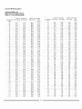
Crown
Molding
Chart
Compound Miter saw
Miter and bevel Angle settings
Wall to Crown MoldingAngle
:......................
52_8_Cro!i_'n
1N'Jdin_.... 45,;'45';'
Cro,¢,trJ
r',,4_,_dini
.........
S_,es_i_w*,
Mi!!iii
_. ring BevelSetting
AngleBetweenrvl=terSetirgBevelSetting NiterSetfir@ Be'_@
AngleBetv,_,een
Mitet°o
Walls
Setting
..............
6i ......................
i293 .................
ii}08 ............
..........
4_89................
08
42,30
40,Kq
48,35
95,89
",NoIIs
128
t957
2320
_S!@Ciii,'iM;i
NiterSettitlg
2221
Bevel
Setting
2070
121
t920
2283
2188
2038
t22
1884
2248
2140
2005
I23
I8 48
2209
2108
1972
70
41,32
40,20
45,28
35,40
124
I8.13
21,71
20.61
19.39
71
4079
3990
4475
35.15
i26
iK77
2i134
202i
i9}06
......................
72....................
4028 ..............................
3961 .............................
4422......................
3489........... [........................
i20...................
ii:_2.....................
2o9_...............................
:i9;8i.........
[ i8:12
......................
i3 ................
74
.....................
3913_..............
............
43:i8 .............
39,25
39,00
4&18
34,3,8
t27
128
t705
167I
2059
2021
19:42
1903
1839
1806
i29
130
t31
132
i613i
t602
I5.67
15,33
i9183
1948
1907
18,89
i81_4
1825
1786
17,48
iii2
3r:
17&_
1705
16,71
183I
1709
lb_8-'_
.....
1430
i765
i832
157O
t383
1879
1656
78
38,24
3&3g
42i5
3&86
77
3774
3000
4184
3360
......................
7,8
.....................
0724
_.................................
0,<7
76
..........................................
41L:3.........................
o303"
s .........................................................
I33
1499
SO
36121
31113
40,i2
3218_
135
i36
81
o5.7.
3581
39,62
._,.,
5o .....
I37
82
3513)
%,@
39113
32,25
I38
..... 83 .......
34183..................
36}ii
3883.............
3i]08
138
..........................................................
84
o486_
a .........
;..............................
358_......................
..............
0814"
..............................................
3178
i@
s_
....
88
3390
%1_S
....
3252
3i}8_
3,453
.............
89 ........... :s21Oi
3@2i
34}28 ............. SH
3i42
i3191
t330
12.96
i20
i7i7
1840
18.02
i5:64
894
1519
1401
i443
830
1502
1488
14.34
i,4100
...............
i_i.....................
SS:X
......................
i_S_......................
iao8....................
qSS_
.......
I42
143
1197
1I 84
14 87
1448
'I
358
1331
13 31
1297
305?
144
t131
1409
1294
1262
30}29 .....
14:_
18..
is,1
i382
12.93.
25
1220
11,83
i2;_8
t59
8 51
1193
11,58
...................
9i......................
3iii
.............
33_3................
.........
3_i9....................
291i......
...............
i48.............
I0.8i.........................
i254 .......................
ii,{6 ................
ii24 ......
g,,,
.0,7,_
33,lg
34,,_
_9,42
t49
g,Sg
12,16
11,09
18,89
93
30.38
32.85
3386
291:13 ..................i58......................
937...................1i77 ......................
1073..................
1055.......
9i
29.86
32.5i
33.i8
28.83
151
905
1138
1036
1020
...............
g_ ............
.....................92111.......................
92194....................
2B_4 ..........
152
873
1099
1000
985
......................
98:...............
..............
2._
q_O
..........
...................
318,.
_...................
...............
3_50J
..........................
28_4
9 .....
i53
814i
10180
963
950
...............
07................. .........
..............
3i48 .............
..........
32103
..................
27:94
.....
154
8.09
i0:2I
9,279,15
:281_J
,
:
_
_:,..
,_
i5_
ilii
982
89i
880
98
311._
_,_
J.64 ......
t56
7,46
8,43
8.55
8,45
99
2774
3078
31'i3
27 3.4
....................
i_?..........................
?ii_ ..............................
908..............................
8i9 ..................
8i0 ...........
100
.7,.q
30,43
30,68
27,03
158
882
855
783
775
......
90
£
3i 62
...... n
33U6
.............
3528
..........
3000
...............
[email protected]_gi ........................
[email protected]................
i46
t47
1068
t0,34
828
747
740
....................
i02
...............................
2050 .............................
2073..................................
2980..........................
2G42...........
i@
820
786
7ii
105
...........
103..................
2809 ........................
2938........................
2938.....................
28:i2....
104
2669
2902
2892
2581
105
_6;'_9"
2867
2848
2550
i06
S£}89
283i
2386
28i9
i0824i0
O g
o
2Ksg
27i9
2.:,32
2293
2236
_.,,1/'_'s
-,
21.79
ii5
2I;42
...................
116..........................
210,4
117
2067
118
2030
ii9
i._;'_3
_ '_'
2887
2851
20;i6
=.,78_
25.42
:
25;0.5
[
2468
_6.:,4
2592
25;@
_..,,O8's_
24,66
23.93
2361
23;20
2,_,.78
_
22.65
24;25
22;83
2i:68..................
23;84 ........22;0i......
2431
2343
2168
2394
2302
21.36
2-.51
s.,
518!
552
5;28
k85
147.
1108
669
630
8;i5
839
6:09
5.88
610
6S:s
81i30
5.65
i_i
40;
5i2
48i
5_9
168
370
472
4.25
424
q
.......... iOg.................
_ ........................
2_}23............................
o2_17...............2424
? .........
110
111
ii2
II._
_
114
i_1
i82
i63
i64
o_,22;6i
2i;02_
169
339
433
390
,989
ii0
3108
"8194
"$54
353
iTi
2177
:35,4
3;i9
318
....................
ii2 ................
............
2]?...........
....................
3}i_...............................
283 .................
283...........
............
iS ...........
.......2;i_..........
............
_% ..................
2@....................
2_7 .....
................
_..................................................................................................
:.......................
:.............
1,4
185
236
22
212
175
1 54
197
177
1 77
ii8
t7"7
I78
i28
0.92
0.62
i:58
1.18
0.79
i}4i
1.06
0.71
i4i
1.06
0,71
............
t79...................
o31...........................
039...................................
o35....................
o3_.s
.......
IVlAINTENANCE
DANGER
Never put lubricants on the blade while it is spinning.
To avoid fire or toxic reaction, never use gasoline,
naphtha acetone, lacquer thinner or similar highly volatile
solvents to clean the miter saw.
To avoid injury from unexpected starting or electrical
shock, unplug the power cord before working on the saw.
For your safety, this saw is double-insulated. To avoid
electrical shock, fire or injury, use only parts identical to
those identified in the parts list. Reassemble exactly as
the original assembly to avoid electrical shock.
LOWER BLADE GUARD
Do not use the saw without the lower blade guard. The
lower blade guard is attached to the saw for your
protection. Should the lower guard become damaged, do
not use the saw until the damaged guard has been
replaced. Develop a regular checkto make sure the
lower guard is working properly. Clean the lower guard of
any dust or buildup with a damp cloth.
CAUTION: Do not use solvents on the guard. They could
make the plastic "cloudy" and brittle.
When cleaning the lower guard, unplug the saw from the
power source receptacle to avoid unexpected startup.
SAWDUST
REPLACING CARBON BRUSHES (FIG. LL)
The carbon brushes fumished will last approximately 50
hours of running time, or 10,000 ON/OFF cycles.
Replace both carbon brushes when either has less than
1/4" length of carbon remaining, or if the spring or wire is
damaged or burned. To inspect or replace brushes, first
unplug the saw. Then remove the black plastic cap (1) on
the side of the motor (2). Remove the cap cautiously,
because it is spring-loaded. Then pull out the brush and
replace. Replace the other side in the same manner. To
reassemble, reverse the procedure. The ears on the
metal end of the assembly go in the same hole the
carbon part fits into. Tighten the cap snugly, but do not
overtighten.
NOTE: To reinstall the same brushes, first make sure the
brushes go back in the way they came out. This will
avoid a break-in period.
Fig. LL
Periodically, sawdust will accumulate under the work
table and base. This could cause difficulty in the
movement of the worktable when setting up a miter cut.
Frequently blow out or vacuum up the sawdust.
If blowing sawdust, wear proper eye protection to keep
debris from entering eyes.
LUBRICATION
All the motor bearings in this tool are lubricated with a
sufficient amount of high grade lubricant for the life of the
unit under normal operating conditions; therefore, no
further lubrication is required.
Lubricate the Following as Required:
Chop pi_t: light machine oil or aerosol will penetrate
from the ends of the junction points. A qualified service
technician can remove the pivot upstop to relieve tension,
and the 2 metric set screws holding the shaft, in order to
drive the shaft about 3/4" right. Exposed surfaces are
lubricated with automotive type oil.
Central pivot of plastic guard: Use light household oil
(sewing machine oil ) on metal-to-metal or
metal-to-plastic guard contact areas as required for
smooth, quiet operation. Avoid excessive oil, to which
sawdust will cling.
Link: (which actuates the lower guard movement) may be
oiled at the rear pivot, greased at ball bearing contact,
and oiled where the link actuates the acetyl roller of the
lower guard, if the down chop motion is hard to start.
Toavoidinjuryfromaccidental
starting,
always
turntheswitchOFFandunplug
thetoolbeforemoving,
replacing
theblade
ormaking
adjustments.
Consult your Sears Service Center if for any reason the motor will not run.
TROUBLESHOOTING
GUIDE-
PROBLEM
Brake does not
stop blade wilhin
6 seconds.
Motor does not
start
Brush spark when
switch released.
TRO UBLESHOOTING
MOTOR
PROBLEM CAUSE
SUGGESTED
1. Motor brushes not sealed or
lightly sticking.
2. Motor brake overheated from
3.
4.
1.
2.
3.
use of defective or wrong si_e
blade or rapid ON/OFF cycling.
Arbor screw loose.
Other.
Fuse
Brush worn.
Other.
1. Brushes Worn/Damaged
G UIDE - SAW OPERATIO
CORRECTIVE
ACTION
1. Inspect/clean /replace brushes. See
MAINTENANCE section.
2.
3.
Use a recommended
Let cool down.
blade.
4.
Retighten.
Contact Sears Service Center.
1. 15-Amp time delay fuse, or circuit breaker.
2. See MAINTENANCE section.
3. Contact Sears Service Center.
1. Replace
Brushes (See Maintenance).
N
PROBLEM
PROBLEM CAUSE
SUGGESTED CORRECTIVE ACTION
Blade hits table.
1. Misalignment.
1. See ADJUSTMENT section.
Angle of cut not
accurate.
Can't adjust miter.
1. Miter table unlocked.
Cutting arm
wobbles.
1. Loose pivot points.
1. Use Miter Quick Lock.
See OPERATION Section.
2. Vacuum or blow out dust,
WEAR EYE PROTECTION.
1. See ADJUSTMENT Section.
Cutting arm won't
fully raise, or
blade guard won't
fully close.
1.
Part failure.
2.
Pivot spring not
replaced properly after
service.
Blade binds, jams,
burns wood.
Saw vibrates or
shakes.
2. Sawdust under table.
3. Sawdust build-up.
1. Improper opera, on.
2. Dull blade.
3. Improper blade size.
4. Warped blade.
1 .Saw blade not round.
2.Saw blade damaged.
&Saw blade loose.
4.Other.
1. Contact Sears Service Center.
2. Contact Sears Service Center.
3. Clean and lubricate mcMng parts.
1. See BASIC SAW OPERATION section.
2. Replace or sharpen blade.
3. Replace with 12" diameter blade.
4. Replace blade.
1.Replace blade.
2.Replace blade.
3. "l]ghten arbor bolt.
4.Contact Sears Smvice Center.
CRAFTSMAN
COM PC UN D MITRE SAW
MODEL : 137.212060
When servicing use only CRAFTSMAN replacement parts, Use of any other parts may create a HAZARD or cause
product damage. Any attempt to repair or replace electrical parts on this Table Saw may create a HAZARD unless repair
is done by a qualified service technician. Repair service is available at your nearest Sears Service Center.
PARTS
LIST FOR SCHEMATIC
A
Qty
I.D. No.
Descdplion
Size
0831
`SHAFT `SLEEVE
6:# COLOR
2258
BOLT
2750
CAUTION
2754
WARNING
2785
2841
ROLL PIN
CENTER,SHAFT
OBBN
C OMPRE,S,SIQN ,SPRING
0CDD
FOOT
0CEZ
PLUNGER
.......8CFX
I.D.No. Description
0KR1
LABEL
b_BEL
Size
Qty
LOCK
NUT
M16>_'.0 T:16
0KR4
LOCK
NUT
IVlgxI ;25 T=@
0K,SP
STRAIN RELIEF
0DE[
HEX, ,SOC, `SETSCREW
23SR
COMPRESSION
25'¢3
KNOB
25V8
KNOB
25XW
TABLE
COLOR
#AW
25XX
BASE
COLOR
#AW
_'L!L_E_I:ATE.............................................................................
25XZ
I_!vq7 BR_ACEET
.............................................................
(p4-22
6:# COLOR
HANDLE
OD7Z
KNOB
25'(0
SLIDING
0DTH
CENTER SHAFT
25Y2
EXTEN'BON
25Y3
SLIDING
28Y6
EXTENllON
25/'8
FENCE
25 '¢'A
tVIITER HANDLE
0DVJ
BLADE WRENCH
0DW5
POWER
0rigA
REAR EXTENTION
0H9W
CLEVIS
CORD
6#
CLAMP
`SUPPORT BAR
PIN
0HA_5
LOCKING
0HAM
DI_T SHIELD
HANDLE
0HAN
COVER
ASS'Y
PLATE
............
oUhR
I_t_,xI ,G25
`SPRING
FENCE - LEFT BIDE
WING
COLOR
#AW
COLOR
#AW
COLOR
#AW
- LEFT SIDE
FENCE - RiGHT,SIDE
WING
25YB
BEVEL HANDLE
25YC
,SLIDE BAR `SEAT (FRONTj
2BYE
`SLIDE-BAR `SEAT (REAR)
...............................................................................................................................................
.........................................................................................................
0HVD
BALL BEARING
0HXX
LINEAR MOTION
608Z
25YK
`SET PLATE
25'Y',,/
0J4N
FLAT WASHER
STOP PLATE (LEF1)
_:,l_0-3
25YW
OJ6A
STOP PLATE (RIGHTJ
FLAT WASHER
@Sxl 6-2,5
0J7K
FDa,TWASHER
318;._9/32-5/64
262Q
262R
BEVEL SCALE POINTER
BEVEL SCALE PQII_ER
OJ88
FLAT WASHER
1O#xl/2
0JSL
FLAT WASHER
1_4W/16-1/16
0JSP
FLAT WASHER
3/8X29/3%5/64
252V
ANCHOR
0J95
0JB0
SPRING WASHER
WAVE WASHER
_P6
WW-8
26HX
GUIDE HOLDER
26NH
NUT
0JB0
WAVE
WW-8
26NN
EXTENSION
0JOG
SPRING
5-16
26NP
BOLT
0JMN
O-RING
0JMP
Q-RING
P7
26NO
26NR
LOCA]ING
BAR
PIVOT SHAFT
OJMT
Q-RING
PS0
2&N`S
LOCKING
OJPP
HEX BOLT
M8×1.25-30
26NT
MITER P_R RIGHT
0JUB
HEX. BOO.
HD, CAP BOLT
M5,_.8-12
26NU
MITER BAR LEFT
OJUK
HEX. BOO.
HD. CAP BOLT
M6x1.0-16
2,SP7
PIVOT BHAFF
0JUM
HEX. ,SOC. HD. CAP BOLT
MTx1.0-25
26PF
HEX. ,SOC, `SETSCREW
0JUW
HEX. `SOC. HD. CAP BOLT
MSxi .25 25
26PU
MITER BAR LOWER
0JXD
HEX. ,SOC. BET SCREW
M6x1.0-25
26U2
EXTEN_ON
0JXG
HEX. ,SOC, SETSCREW
MSx1.25-16
26U6
QUICGCAM
0JZF
HEX. ,BOO. BET,SCREW
M6x1 .O-10
26UG
CAM
OK2P
HEX.,SOCKET
MTX1,25-40
25UH
PO,SITWE STOP LOCKING
OK55
OR. RE. COUbff
M5_.8-8
0K74
CR.-RE. TRU,S,SHD. SCREW
26UQ
26U'S
BEVEL,SCALE
MITER SCALE
0KTF
OR. RE. ROUND
M6,_0-8
274Z
BEVEL LOCK
OK7X
CR RE TRUSS HD ROUND NECK SCREW
M6XI.O-IO
27BU
TABLE INSERT-
RIGHT SIDE
OKAD
OR. RE. TRU,SB HD. TAPP{NG
`SCREW
M4,@.7-8
278V
TABLE INSERT-
LEFT,SIDE
0KAE
OR. RE. TRUSS HD. TAPPING
SCREW
M5>9.8-10
27H1
CLAMP-COR
0KAE
OR.RE.
27HE
TOR,SfON `SPRING
BEARING
WASHER
PiN
HD.CAP
SCREW
HD, SCREW
WASHER
1/16
M6x1.0-8
HD. SCREW
PAN HD. TAPPING,SCREW
......
M58'0,8-10
262S
POWER
CORD
262T
FENCE
PLATE
STORAGE
CLIP
P bS,TE
]UBE
ROD
WING
IvIDx1.2_5-_,
,'sS,S'Y- LEFT & RIGHT
MITER TABLE LOCK
LOCKING
ASSY,
LDJER AS,BY,
LEVER ASS'(.
LABEL
D
.................
0KD9
CR. RE. PAN
HD. SCREW
M4:@.7-16
27J9
`SET NLFI
0KDG
OR, RE. PAN
HD. SCREW
M5_.8-6
27JA
SCREW
0KDH
OKDH
OR. RE. PAN
OR. RE. PAN
HD. `SCREW
HD. SCREW
M5_.8-8
MBxO.8-8
27KA
27KP
ECCENTRIC SPANNER SEAT
SLIDE CARRIAGE
COVER PLAIE
OKDM
OR, RE. PAN
HD, SCREW
M5,13.8-20
OKDR
OR. RE. PAN
HD. `SCREW
M5_.8-lO
27MN
ANCHOR
0KDU
OR. RE, PAN
HD. SCREW
M6x1,0-12
27PS
EXTENSION
TABLE _S'Y-LEFT
0KDV
OR. RE. PAN
HD. ,SC;REW
M4x1.0-16
27PT
EXTENSION
TABLE A_,S'Y-RIGHT
CIR_ RE..pAF4
HEX. NUT
HE_. SCRE_t_(..............................
MS:if9 _6-6.................................................
2 _"{_
UEXi,soc, ,sBrSgBE:,p,_
....................................
!!E@':hg:
!6 .................................
M6xl .O T=-5
283G
HEX,SQCKET HD,CAP
SCREW'
f',/_B_O.G2O
........
9_F9
OKMB
0KMY
HEX. NLrF
M8×1.25
0K©Z
LOCK
f'41O;d ,5 T=IO
NUT
T=6.5
27L1
RO
2J_,H
CAM
STOP
LOCKING
LEVER AS`BY,
PB_TE
HEX. ,SQC. HD. CAP
BOLT
M5:gS.P_]2
CRAFTSMAN
SCHEMATIC A
COMPOUND
MITRE SAW
MODEL : 137.212060
CRAFTSMAN
COMPOUND
MITRE
MODEL : 137.212060
SAW
PARTS LIST FOR SCHEMATIC B
I.D. No.
Size
Description
Qty
I.D. No, Description
Size
MOTOR ASS'Y
1
OKC6
CR. RE.TRUSS HD, TAPPING SCREW
2751
MOTOR LABEL
1
OKD4
CR. RE. PAN HD. SCREW
2752
TRADDMARK
1
OKD8
CR. RE. PAN HD. SCREW
M4_J.7-12
2753
TILTING SCALE
1
OKDH
OR. RE. PAN HD. SCREW
M5xO.8_8
1
083Z
CLAMP-CORD
1
OKDV
CR. RE. PAN HD. SCREW
M6xl.0-1&
5
OBSZ
CLAMP-CORD
1
OKKK
CR.RE. PANHD. ROUNDNECKSCREW
M6xl.0q2
1
084J
CUSHION
1
OK©Y
NUT
tCL_x1.25T=_
1
_4K
SETPLAZE
]
OKTP
CABLE CLAMP
084M
STOP CLAMP
1
OS2X
LOCK HANDLE ASS'Y
084Q
COMPRESSION SPRING
1
14,@,," HEX WASHER HD BOLT
OCH1
SHAFT-PIVOT
1
246V
TRIGGER SWITCH
1
OCH2
SLEEVE
1
25 NZ
LASER ASS'Y
1
OCHF
SPRING GUARD
1
25Y1
ARM
1
OCKM
TRIGGER
1
25Y7
BELTCOVER
1
ODTZ
ARBOR COLLAR
1
25YJ
HANDLE -TOP
1
OFHW
COLLAR
1
25YL
HANDLE- BOTTOM
1
OHB3
BLADE
1
25YM
CARRY HANDLE-TOP
]
OJ4E
FLAT WASHER
@_5x13-1
]
25YN
CARRY HAN DLE- BOTTOM
1
OJ4E
FLAT WASHER
,(p&x13-1
1
25YR
PLATE
1
OJ4E
FLAT WASHER
_ 6X13-1
4
25YU
DUST BAG ASSY,
OJ4W
FLAT WAHSER
_#8.2X18-1.5
1
262N
CARRY HANDLE-
0J53
FIAT WASHER
@8.4;,:24-2
1
2_2U
GEAR BOX COVER
1
0J92
SPRING WASHER
¢_5
4
267Y
PULLEY
1
26Eq
POWER CABLE
1
LABEL
M4x6-12
Qty
2594
M&xl.O-lO
1
2
2
1
1
/V6x1.25-1&
1
1
REAR
]
0J95
SPRING WAS;HER
cp4
4
OJBO
WAVE WASH ER
WW45
1
26H6
BELT
1
OJBO
WAVE WASH ER
WW_
1
26P8
iNSULATING SLEEVE
1
OJB2
WAVE WASH ER
WW-12
1
26PE
LEAD Wl RE ASS'Y
1
og BS
WAVE WASH ER
WWq 4
1
2,SPW
SPACER
1
OJET
E-RING
E-4
1
26U8
LOCKING HANDLE ASS'Y
1
OJUC
HEX. SOC. HD. CAP BOLT
MSxO.Sq t}
2
26UJ
PC-GUARD ASS'¥
1
OJUJ
HEX.SOC. HD. CAP BOLT
M4}x1.0-12
4
26UK
GEARSHAFT
1
OJUL
HEX.SOC. HD. CAP BOLT
M4,x1.0-20
4
26UL
CUTTERSHAFT ASS'Y
OJUX
HEX. SOC. HD. CAP BOLT
MBx125-30
2
27BC
SAFETY HOLD-DOWN
OJV2
HEX.SOC. HD. CAP BOLT
MSx125-69
1
27KD
LEVER
1
27KE
CUTTER SHAFT GUARD
1
ASS'Y
1
CLAMP
1
OJVQ
HEX.SOC. HD. CAP BOLT
MSx1.25-50
1
M6x1.0-1
2
27KY
CLAMP BOLT
1
M6x] .0-1
]
27LP
LOCK KNOB
1
OJXB
HEX.SOC. SETSCREW
OK1N
HEX. HD. SCREWAND
OK4D
CR.RE. PAN HD.SCREW & WASHER M4xl.0-12
1
27LU
WARNINGLABEL
OK7X
CR. RE.TRU&SHD. ROUNDNECK5CREw M6X1.0-10
2
27PF
COMPRE%ION
SPRING
1
OKB6
CR,RE, PAN HD.TAPPINGSCREW
M4X18-35
S
27WC
COMPRESSION SPRING
1
OKB7
CR.RE. PAN HD.TAPPINGSCREW
M4X18-16
2
OKB8
OR.RE. PAN HD.TAPPINGSCREW
M4X18-20
2
279X
INSTRUCTION MANUAL
WASHER
1
Ill
-I
0
0
0
C
z
;ll
m
\
2
Di<?i
)
0
0
m
r-
L_
7
0
o
CRAFTSMAN
COMPOUND
MITRE SAW
MODEL :137.212060
PARTS LIST FOR MOTOR
I.D. No,
OHUT
Descdplion
BALL BEARING
Size
6203LLB
Qfy
1
OHVU
BALL BEARING
62COZZ
1
OJ70
FLAT WAS HER
]/4:43/4-7/64
1
OJB
WAVE WASHER
BWW62_J
1
OJPD
HEX. HD. BOLT
M6xl.0q
OJX3
HEX. SOC. SF SCREW
M5"xO.8_
2
OJYS
HEX. SOC. SETSCREW
M6x1.0-16
]
6
1
OKST
CR.RE. PAN HD, SCREW & WASHER
M5XO.8-25
2
OK3Y
CR.-RE. PAN HD. 5CREW &: WASH ER
M5×0.8-50
2
0K72
CR.-RE.TRUSB HD. SCREW
MSXO,8-12
2
OKC©
CR.-RE,PAN HD.TAPPING SCREW& WASHER
M5×12-&5
2
M5 _:0.8-6
2
OKLA
PLASTIC SCREW
OQ9K
FLOW GUIDE
OQAA
MOTOR HOUSING ASS'Y
#6
1
O©M2
BRUSH HOLDER ABS'Y
@27s265
2
OQ©T
BRUSHAS.S'Y
2
O©RO
BRUSHCOVER
2
O©R1
RUBBER PiN
1
269C
MOTOR PULLEY
1
1
26AZ
ARMATU RE ASS'Y
26CB
FIELD ASS'Y
26DF
FRONT HOUSING
]
1
AW# COLOR
1
0
0
"11
Z
0
0
C
Z
--I
rrl
t_
)
0
U
I"1'1
r-
I,o
o
o