1
OPERATORS MANUAL .
MARINE DIESEL ENGINES
308· THREE 30C·THREE
208-TWO
PUBLICATION N0.36906
REVISION FIVE
JANUARY 2011
WESTERBEKE CORPORATION • 150 JOHN HANCOCK ROAD
MYLES STANDISH INDUSTRIAL PARK• TAUNTON MA 02780
WEBSITE: WWW. WESTERBEKE.COM
...........__.
NAMIA
~,.,.,
Member National Marine Manufacturers Association
.
A
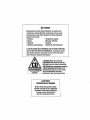
wARNING··
Exhaust gasses contain Carbon Monoxide, an odorless ani/
colorless gas. Carbon Monoxide is poisonous and can cause
unconsciousness and death. Symptoms of Carbon Monoxide
exposure can include:
• Throbbing in Temples
•Dizziness
• Muscular Twitching
•Nausea
•Headache
• Vomiting
• Weakness and Sleepiness •Inability to Think Coherently
IF. YOU OR ANYONE ELSE EXPERIENCE ANY OF THESE SYMPTOMS,
GET OUT INTO THE FRESH AIR IMMEDIATELY. If symptoms persist,
seek medical attention. Shut down the unit and do not resta/1
until it has been inspected and repaired.
.....__'WJ_
...._~_-_.s_eKlf____
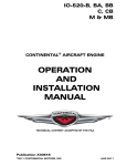
A WARNING DECAL is provided by
WESTERBEKE and should be fixed to a
bulkhead near your engine or generator.
WESTERBEKE also recommends installing
CARBON MONOXIDE DETECTORS in the
livirlg/sleeping quarters of your vessel.
They are inexpensive and easily
obtainable at your local marine store.
CALIFORNIA
PROPOSITION 65 WARNING
Marine diesel and gasoline engine
exhaust and some of its constituents
are known to the State of California
to cause cancer, birth defects,
and other reproductive harm.
SAFETY INSTRUCTIONS
INTRODUCTION
PREVENT BURNS - FIRE
Read this safety· manual carefully. Most accidents are
caused by failure to follow fundamental rules and precautions. Know when dangerous conditions exist and take the
necessary precautions to protect yourself, your personnel,
and your machinery.
The following safety instructions are in compliance with
the American Boat and Yacht Council (ABYC) standards.
•
PREVENT ELECTRIC SHOCK
•
A WARNING: Do not touch AC electrical connections
while engine is running, or when connected to shore
power. Lethal voltage is present at these connections!
•
•
•
•
•
•
•
Do not operate this machinery without electrical
enclosures and covers in place.
Shut off electrical power before accessing electrical
equipment.
Use insulated mats whenever working on electrical
equipment.
Make sure your clothing and skin are dry, not damp
(particularly shoes) when handling electrical equipment.
Remove wristwatch and all jewelry when working on
electrical equipment.
Do not connect utility shore power to vessel's AC
circuits, except through a ship-to-shore double throw
transfer switch. Damage to vessel's AC generator may
result if this procedure is not followed.
Electrical shock results from handling a charged capacitor. Discharge capacitor by shorting terminals together.
A WARNING: Fire can cause injury or death!
•
Do not operate with the air cleaner/silencer removed.
Backfire can cause severe injury or death.
•
Do not smoke or permit flames or sparks to occm near
the fuel system. Keep the compartment and the
engine/generator clean and free of debris to minimize the
chances of fire. Wipe up all spilled fuel and engine oil.
Be aware - diesel fuel will burn.
•
PREVENT BURNS - EXPLOSION
A WARNING: Explosions from fuel vapors can cause
injury or death!
•
Follow re-fueling safety instructions. Keep the vessel's
hatches closed when fueling. Open and ventilate cabin
after fueling. Check below for fumes/vapor beforemnning the blower. Run the blower for four minutes before
starting your engine.
•
All fuel vapors are highly explosive. Use extreme care
when handling and storing fuels. Store fuel in a well-ventilated area away from spark-producing equipment and
out of the reach of children.
•
•
Do not fill the fuel tank(s) while the engine is running.
Shut off the fuel service valve at the engine when servicing
the fuel system. Take care in catching any fuel that might
spill. DO NOT allow any smoking, open flames, or other
sources of fire near the fuel system or engine when servicing. Ensure proper ventilation exists when servicing the
fuel system.
•
•
Do not alter or modify the fuel system.
Be sure all fuel supplies have a positive shutoff valve.
•
Be certain fuel line fittings are adequately tightened and
free of leaks.
Make sure a fire extinguisher is installed nearby and is
properly maintained. Be familiar with its proper use.
Extinguishers rated ABC by the NFPA are appropriate
for all applications encountered in this environment.
PREVENT BURNS - HOT ENGINE
A WARNING: Do not touch hot engine parts or
exhaust system components. A running engine gets
very hot!
•
Always check the engine coolant level at the coolant
recovery tank.
A WARNING: Steam can cause injury or death!
•
In case of an engine overheat, allow the engine to cool
before touching the engine or checking the coolant.
Prevent flash fires. Do not smoke or permit flames or
sparks to occur near the carburetor, fuel line, filter, fuel
pump, or other potential sources of spilled fuel or fuel
vapors. Use a suitable container to catch all fuel when
removing the fuel line, carburetor, or fuel filters.
Do not operate with a Coast Guard Approved flame
arrester removed. Backfire can cause severe injury or
death.
•
SAFETY INSTRUCTIONS
ACCIDENTAL STARTING
TOXIC EXHAUST GASES
A WARNING: Accidental starting can cause injury
A WARNING: Carbon monoxide (CO) is a deadly gas!
or death!
•
•
•
Disconnect the battery cables before servicing the engine/
generator. Remove the negative lead first and reconnect
it last.
Make certain all personnel are clear of the engine before
starting.
Make certain all covers, guards, and hatches are reinstalled before starting the engine.
•
Ensure that the exhaust system is adequate to expel gases
discharged from the engine. Check the exhaust system
regularly for leaks and make sure the exhaust manifolds
are securely attached and no warping exists. Pay close
attention to the manifold, water injection elbow, and
exhaust pipe nipple.
•
•
Be sure the unit and its surroundings are well ventilated.
In addition to routine inspection of the exhaust system,
install a carbon monoxide detector. Consult your boat
builder or dealer for installation of approved detectors.
•
For additional information refer to ABYC T-22 (educational information on Carbon Monoxide).
BATTERY EXPLOSION
A WARNING: Battery explosion can cause injury
or death!
•
•
•
•
A WARNING: Carbon monoxide (CO) is an invisible
Do not smoke or allow an open flame near the battery
being serviced. Lead acid batteries emit hydrogen, a
highly explosive gas, which can be ignited by electrical
arcing or by lit tobacco products. Shut off all electrical
equipment in the vicinity to prevent electrical arcing during servicing.
Never connect the negative(-) battery cable to the positive (+) connection terminal of the starter solenoid. Do
not test the battery condition by shorting the terminals
together. Sparks could ignite battery gases or fuel vapors.
Ventilate any compartment containing batteries to prevent
accumulation of explosive gases. To avoid sparks, do not
disturb the battery charger connections while the battery
is being charged.
Avoid contacting the terminals with tools, etc., to prevent
burns or sparks that could cause an explosion. Remove
wristwatch, rings, and any other jewelry before handling
the battery.
Always turn the battery charger off before disconnecting
the battery connections. Remove the negative lead first
and reconnect it last when disconnecting the battery.
odorless gas. Inhalation produces nu-1/ke symptoms,
nausea or death!
•
Do not use copper tubing in diesel exhaust systems. Diesel
fumes can rapidly destroy copper tubing in exhaust systems. Exhaust sulfur causes rapid deterioration of copper
tubing resulting in exhaust/water leakage.
•
Do not install exhaust outlet where exhaust can be drawn
through portholes, vents, or air conditioners. If the engine
exhaust discharge outlet is near the waterline, water could
enter the exhaust discharge outlet and close or restrict the
flow of exhaust. Avoid overloading the craft.
Although diesel engine exhaust gases are not as toxic as
exhaust fumes from gasoline engines, carbon monoxide
gas is present in diesel exhaust fumes. Some of the symptoms or signs of carbon monoxide inhalation or poisoning
are:
Vomiting
Muscular twitching
Dizziness
Intense headache
•
Throbbing in temples
BAnERYACID
AVOID MOVING PARTS
A WARNING: Sulfuric acid in batteries can cause
A WARNING: Rotating parts can cause injury
severe injury or death!
•
Weakness and sleepiness
or death!
When servicing the battery or checking the electrolyte
level, wear rubber gloves, a rubber apron, and eye protection. Batteries contain sulfuric acid which is destructive.
If it comes in contact with your skin, wash it off at once
with water. Acid may splash on the skin or into the eyes
inadvertently when removing electrolyte caps.
•
Do not service the engine while it is running. If a situation arises in which it is absolutely necessary to make
operating adjustments, use extreme care to avoid touching moving parts and hot exhaust system components.
Engines & Generators
ii
SAFETY INSTRUCTIONS
•
•
•
•
ABYC, NFPA AND USCG PUBLICATIONS FOR
INSTALLING DIESEL ENGINES
Do not wear loose clothing or jewelry when servicing
equipment; tie back long hair and avoid wearing loose
jackets, shirts, sleeves, rings, necklaces or bracelets that
could be caught in moving parts.
Read the following ABYC, NFPA and USCG publications
for safety codes and standards. Follow their recommendations when installing your engine.
ABYC (American Boat and Yacht Council)
"Safety Standards for Small Craft"
Make sure all attaching hardware is properly tightened.
Keep protective shields and guards in their respective
places at all times.
Do not check fluid levels or the drive belt's tension while
the engine is operating.
Order from:
ABYC
3069 Solomon's Island Rd.
Edgewater, MD 21037
NFPA (National Fire Protection Association)
"Fire Protection Standard for Motor Craft"
Order from:
Stay clear of the drive shaft and the transmission coupling
when the engine is running; hair and clothing can easily
be caught in these rotating parts.
HAZARDOUS NOISE
A WARNING: High noise levels can cause hearing
NFPA
11 Tracy Drive
Avon Industrial Park
Avon, MA 02322
USCG (United States Coast Guard)
"USCG 33CFR183"
Order from:
U.S. Government Printing Office
Washington, D.C. 20404
loss!
•
•
•
Never operate an engine without its muffler installed.
Do not run an engine with the air intake (silencer)
removed.
Do not run engines for long periods with their enclosures
open.
A WARNING: Do not work on machinery when you are
mentally or physically incapacitated by fatigue!
OPERATORS MANUAL
Many of the preceding safety tips and warnings are repeated
in your Operators Manual along with other cautions and
notes to highlight critical information. Read your manual
carefully, maintain your equipment, and follow all safety
procedures.
ENGINE INSTALLATIONS
Preparations to install an engine should begin with a thorough examination of the American Boat and Yacht Council's
(ABYC) standards. These standards are a combination of
sources including the USCG and the NFPA.
Sections of the ABYC standards of particular interest are:
H-2 Ventilation
P-1 Exhaust systems
P-4 Inboard engines
E-9 DC Electrical systems
All installations must comply with the Federal Code of
Regulations (FCR).
Engines & Generators
iii
INSTALLATION
When installing WESTERBEKE engines and generators it is important that strict
attention be paid to the following information:
CODES. AND REGULATIONS
Strict federal regulations, ABYC guidelines, and safety codes must be complied with
when installing engines and generators in a marine environment.
SIPHON-BREAK
For installations where the exhaust manifold/water injected.e;iliaust elbow is close to
or will be below the vessel's waterline, provisions mu~t be made to install a siphonbreak in the raw water supply hose to the exhaust elbow. This hose must be looped a
minimum of 20" above the vessel's waterline. Failure to use a siphon-break when
the exhaust manifold/water injected exhaust elbow is near or below the loaded
water line of the vessel will result in raw water damage to the engine and possible
flooding of the vessel.
If you have any doubt about the position of the water-injected exhaust elbow relative
to the vessel's waterline under the vessel's various operating conditions, install a
siphon-break.
NOTE: A siphon-break requires periodic inspection and cleaning to ensure proper
operation. Failure to properly maintain a siphon-break can result in catastrophic
engine damage. Consult the siphon-break manufacturer for proper maintenance.
EXHAUST SYSTEM
The exhaust hose must be certified for marine use. The system must be designed to
prevent water from entering the exhaust under any sea conditions and at any angle
A detailed Marine Installation Manual covering gasoline and diesel
engines and generators Is supplied with every unit sold. This manual
.is also available in pdf format on our website to download
Website: www.westerbeke.com
Engines & Generators
iv
AVAILABLE FROM
YOUR WESTERBEKE
DEALER
TABLE OF CONTENTS
Parts Identification ................................................2
lntroduction .............................................................3
Glow Plugs .........................................................28
Starter Motor .....................................................29
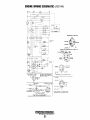
Engine Wiring Diagram (#39144) ...................... 30
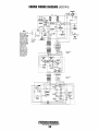
Engine Wiring Schematic (#39144) ................... 31
Admirals Panel Wiring Diagram (#36844) ......... 32
Admirals Panel Wiring Schematic (#36844) ..... 33
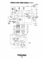
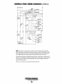
Captains Panel Wiring Diagram (#36467) ........ .34
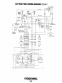
Captains Panel Wiring Schematic (#36467) ..... 35
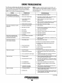
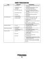
Engine Troubleshooting .....................................36
Warranty Procedures ......................................... 3
Serial Number Location .................................. .4
Fuel, Engine Oil and Coolant ..............................5
Admiral Control Panel .........................................6
Captain Control Panel .........................................7
Preparations for Initial Start-Up ......................... 8
Starting/Stopping Procedure ...............................9
Engine Break-In Procedure ............................... 1o
Warning Lights, Alarms and Circuit Breaker .... 11
Maintenance Schedule ..................................... 12
'
Fuel System
....................................................... 14
Control Panel Troubleshooting ....................... 38
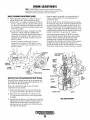
Engine Adjustments .............................................39
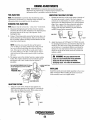
Adjusting Idle Speed ...................................... 39
Fuel/Run Shut-Off Solenoid ........................ _39
Drive Belt Adjustment .................................. .40
Engine Compression ...................................... .40
Testing Oil Pressure ....................................... .41
Oil Pressure Switch ....................................... .41
Valve Clearance Adjustment ......................... .42
Cylinder Head Bolt Tightening ..................... .42
Injection Timing ............................................ .43
Fuel Injectors .................................................. 44
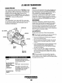
JS and BW, Transmissions ................................ .45
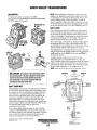
Hurth HBW/ZF Transmissions ........................... .47
PRM Newage Transmissions ............................. 52
Fuel/Water Filter ............................................. 14
Fuel Filters ...................................................... 14
Cooling System .................................................. 15
Changing Coolant. .......................................... 16
Thermostat ...................................................... 17
Raw Water Intake Strainer. ............................. 18
Raw Water Pun1p-............................................ 18
Raw Water Pump Parts Breakdown ............ 18A
Heat Exchanger .............................................. 19
Zinc Anode ................................................... -19
Engine Lubricating Oil .......................................20
Changing the Oil Filter ................................... 20
Changing the Oil ........................................... 20
Remote Oil Filter (Optional) ..............................21
Water Heater .....................................................22
Tachometer ........................................................24
Alternator Testing/Troubleshooting .................. 25
Battery Care .................................................... 27
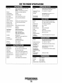
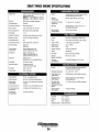
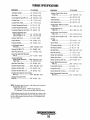
Engine Specifications .......................................55
Lay-up and Recommissioning ........................... 57
Torque Specifications .......................................59
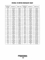
Metric Conversions Data ...................................60
Suggested Spare Parts ......................................62
1~/WESIERBEKE
Enalnss & GeneMtors
1
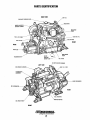
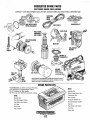
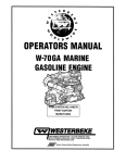
PARTS IDENTIFICATION
RIGHT SIDE
Oil Fill
COOlANT PRESSURE CAP
•SIDE Oil Fill
FRONT
REAR
BlOCK
COOlANT
DRAIN PlUG
'RAW WATER
PUMP
Oil FilTER
LEFT SIDE
AIR INTAKE SilENCER
; NIT 1.0. PlATE
THERMOSTAT
ASSEMBlY
oc
REAR
MOTOR
Oil DRAIN
FRONT
Engine$ & Generators
2
INTRODUCTION
PRODUCT SOFTWARE
This WESTERBEKE Diesel Engine is a product of
WESTERBEKE's long years of experience and advanced
technology. We take great pride in the superior durability and
dependable performance of our engines and generators.
Thank you for selecting WESTERBEKE.
Product software, (tech data, parts lists, manuals,
brochures and catalogs), provided from sources other than
WESTERBEKE are not within WESTERBEKE's control.
WESTERBEKE CANNOT BE RESPONSIBLE FOR THE
CONTENT OF SUCH SOFTWARE, MAKES NO WARRANTIES OR REPRESENTATIONS WITH RESPECT
THERETO, INCLUDING ACCURACY, TIMEliNESS OR
COMPLETENESS THEREOF AND WILL IN NO EVENT
BE UABLE FOR ANY TYPE OF DAMAGE OR INJURY
INCURRED IN CONNECTION WITH OR ARISING OUT
OF THE FURNISHING OR USE OF SUCH SOFTWARE.
In order to get the full use and benefit from your generator it
is important that you operate and maintain it correctly. This
manual is designed to help you do this. Please, read this
manual carefully and observe all the safety precautions
throughout. Should your engine require servicing, contact
your nearest WESTERBEKE dealer for assistance.
This is your operators manual. A parts catalog is also
provided and a technical manual is available from your
WESTERBEKE dealer. If you are planning to install this
equipment contact your WESTERBEKE dealer for
WESTERBEKE'S installation manual.
Your WESTERBEKE Warranty is included in a separate
folder. If, after 60 days of submitting the Warranty Registry
form you have not received a customer identification card
registering your warranty, please contact the factory in
writing with model information, including the unit's serial
number and commission date.
WESTERBEKE customers should also keep in mind the
time span between printings of WESTERBEKE product
software and the unavoidable existence of earlier
WESTERBEKE manuals. In summation, product software
provided with WESTERBEKE products, whether from
WESTERBEKE or other suppliers, must not and cannot
be relied upon exclusively as the definitive authority on
the respective product. It not only makes good sense
but is imperative that appropriate representatives of
WESTERBEKE or the supplier in question be consulted
to determine the accuracy and currentness of the
product software being consulted by the customer.
Customer Identification Card
NOTES, CAUTIONS AND WARNINGS
WARRANTY PROCEDURES
As this manual takes you through the operating procedures,
maintenance schedules, and troubleshooting of your marine
engine, critical infom1ation will be highlighted by NOTES,
CAUTIONS, and WARNINGS. An explanation follows:
I~IWESTERBEKE
JEngines & Generators
Customer Identification
MR. ENGINE OWNER
MAIN STREET
HOMETOWN, USA
Model
Expires
NOTE: An operating procedure essential to note.
A CAUTION: Procedures, which if not strictly
observed, can result in the damage or destruction of
your engine.
Ser. #
A WARNING: Procedures, which if not properly
followed, can result in personal injury or loss of life.
3
INTRODUCTION
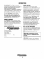
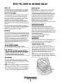
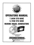
SERIAL NUMBER LOCATION
ORDERING PARTS
The engine's model number and serial number are located on
a nameplate mounted on the side of the engine's manifold.
The engine's serial number is stamped into the engine block
on the flat surface directly above the injection pump. Take
the time to enter this information on the illustration of the
nameplate shown below, as this will provide a quick
reference when seeking technical information and/or ordering
parts.
Whenever replacement parts are needed, always provide the
engine model number and serial number as they appear on
the silver and black name plate located on the manifold. You
must provide us with this information so we may properly
identify your engine. In addition, include a complete part
description and part number for each part needed (see the
separately furnished Parts List). Insist upon WESTERBEKE
packaged parts because will fit or generic parts are frequent! y
not made to the same specifications as original equipment.
SPARES AND ACCESSORIES
Certain spares will be needed to support and maintain your
WESTERBEKE engine. Your local WESTERBEKE dealer
will assist you in preparing an inventory of spare parts. See
the SPARE PARTS page in this manual. For Engine
Accessories, see WESTERBEKE'S ACCESSORIES
brochure.
Fill in the in}onnation for your reference. ~
UNDERSTANDING THE DIESEL ENGINE
INSTALLATION MANUAL
The diesel engine closely resembles the gasoline engine,
since the mechanism is essentially the same. The cylinders
are arranged above a closed crankcase. The crankshaft is the
same general type as a gasoline engine, and the diesel engine
has the same types of valves, camshaft, pistons, connecting
rods and lubricating system.
Publication #43400 provides detailed information for
installing engines.
PROTECTING YOUR INVESTMENT
Care at the factory dming assembly and thorough testing
have resulted in a WESTERBEKE engine capable of many
thousands of hours of dependable service. However the
manufacturer cannot control how or where the engine is
installed in the vessel or the manner in which the unit is
operated and serviced in the field. This is up to the
buyer/owner-operator.
Therefore, to a great extent, a diesel engine requires the
same preventive maintenance as a gasoline engine. The
most important factors are proper ventilation and proper
maintenance of the fuel, lubricating and cooling systems.
Fuel and lubricating filter elements must be replaced at the
time periods specified, and frequent checking for
contamination (water, sediment, etc.) in the fuel
system is also essential. Another important factor is the
consistent use of the same brand of high detergent diesel
lubrication oil designed specifically for diesel engines.
The diesel engine does differ from the gasoline engine,
however, in its method of handling and firing offuel. The
carburetor and ignition systems are replaced by a single
component- the fuel injection pump- which performs the
function of both.
GLOW PLUG·
ENERGIZED BY THE PREHEAT
NOTE: Six important steps to ensure long engine life:
• Proper engine installation and alignment.
• An efficient well-designed exhaust system that includes
an anti-siphon break to prevent water from entering the
engine.
• Changing the engine oil and oil filters every 100
operating hours.
• Proper maintenance of all engine and generator
components according to the maintenance schedule in
this manual.
tTTrlnt...,......,
• Use clean, filtered diesel fuel.
• Winterize your engine according to the "Lay-up and
Recommissioning" section in this manual.
PRE-cOMBUSTION CHAMBER.....-;;:~~~~~
~
Engines & Generators
4
DIESEL FUEL, ENGINE OIL AND ENGINE COOLANT
DIESEL FUEL
ENGINE COOLANT
USE A DIESEL FUEL WITH A CETANE RATING OF #45 OR HIGHER.
(No. 2-D (SAE J313) diesel fuel according to ASTM D975).
'WESTERBEKE recommends a mixture of 50% antifreeze
and 50% distilled water. Distilled water is free from the
chemicals that can cmrode internal engine surfaces.
The antifreeze performs double duty. It allows the engine to
run at proper temperatures by transferring heat away from
the engine to the coolant, and lubricates and protects the
cooling circuit from rust and conosion. Look for a good
quality antifreeze that contains Supplemental Cooling
Additives (SCAs) that keep the antifreeze chemically
balanced, crucial to long term protection.
The distilled water and antifreeze should be premixed before
being poured into the cooling circuit.
Care Of The Fuel Supply
Use only clean diesel fuel! The clearance of the components
in your fuel injection pump is very critical; invisible dirt
particles which might pass through the filter can damage
these finely finished parts. It is important to buy clean fuel,
and keep it clean. The best fuel can be rendered
unsatisfactory by careless handling or improper storage
facilities. To assute that the fuel gping into the tank for your
engine's daily use is clean and pure, the following practice is
,,
r;' '
advisable:
PURCHASING ANTIFREEZE
Purchase a well-known brand of fuel.Install and regularly
service a good, visual-type fuel filter/water separator between
the fuel tank and the engine. The Raycor 500 MA or 230
RMAM are good examples of such filters.
Rather than preparing the mixture, WESTERBEKE
recommends buying the premixed antifreeze so that so that
when adding coolant the mixture will always be correct.
There are two common types of antifreeze, Ethylene Glycol
(green) and Propylene Glycol (red/purple), either can be used
but do not mix the two and if changing from one to another,
flush the engine thoroughly.
ENGINE OIL
Use a heavy duty engine oil with an API classification of CF,
CG-4, CH-4 or CI-4. Change the engine oil and filter after an
initial 50 hours of break-in operation. Then follow the oil and
filter change intervals as specified in the MAINTENANCE
SCHEDULE in this manual. Westerbeke Corporation does
not approve or disapprove of the use of synthetic oils. If
synthetic oils are used, engine break-in must be performed
using conventional oil. Oil change intervals must be as in the
MAINTENANCE SCHEDULE, not extended because
synthetic oils are used.
Premixed antifreeze for DIESEL Engines:
Specification #ASTM D53456.
MAINTENANCE
Change the engine coolant every five years regardless of the
number of operating hours as the chemical additives that
protect and lubricate the engine have a limited life.
COOLANT RECOVERY TANK
SAE OIL VISCOSITY GRADES
A coolant recovery tank kit is supplied with each
engine or generator. The purpose of this recovery tank is to
allow for engine coolant expansion and contraction duting
engine operation, without the loss of coolant and without
introducing air into the cooling system. This kit is provided .
:..nd must be installed before operating the engine.
For all temperatures use SAE 10W-30 or 15W-40.
A
CAUTION: Do not allow two or more brands of
engine oil to mix. Each brand contains its own atJditives;
additives of different brands could react in the mipure
to produce properties harmful to your engine.
,.,>
OIL PRESSURE
The engine's oil pressure, during operation, is indicated
by the oil pressure gauge on the instrument panel. During
nonnal operation, the oil pressure will range between 35 and
65 psi 2.5 and 3.9 kg/cm2).
NOTE: A newly started, cold engine can have an oil pressure
reading upwards of 60 psi (4.2 kg/cm2l. A warmed engine can
have an oil pressure reading as low as 25 psi (1.8 kg!cm2l.
These readings will vary depending upon the temperature of
the engine, the load placed on the engine, and the RPM's.
Engines & Generators
5
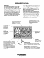
ADMIRAL CONTROL PANEL
DESCRIPTION
When the engine is shut down with the key switch turned off,
the water temperature gauge will continue to register the last
temperature reading indicated by the gauge before electrical
power was turned off. The oil pressure gauge will fall to zero
when the key switch is turned off. The temperature gauge
will once again register the engine's true temperature when
electrical power is restored to the gauge.
A separate alann buzzer with harness is supplied with every
Admiral Panel. The installer is responsible for electrically connecting the buzzer to the four-pin connection on the engine's
electrical harness. The installer is also responsible for installing
the buzzer in a location where it will be dry and where it will
be audible to the operator should it sound while the engine is
running. The buzzer will sound when the ignition key is turned
on and should silence when the engine has started and the
engine's oil pressure rises above 15 psi (1.1 kg/cm2).
This manually-operated control panel is equipped with a
KEY switch and RPM gauge with an ELAPSED TIME
meter which measures the engine's running time in hours and
in 1/10 hours. The panel also includes a WATER TEMPERATURE gauge which indicates water temperature in degrees
Fahrenheit, an OIL PRESSURE gauge which measures the
engine's oil pressure in pounds per square inch, and a DC
control circuit VOLTAGE gauge which measures the system's voltage. All gauges are illuminated when the key
switch is turned on and remain illuminated while the engine
is in operation. The panel also contains two rubber-booted
pushbuttons, one for PREHEAT and one for START.
OIL PRESSURE GAUGE: THIS GAUGE IS GRADUATED IN POUNDS PER SQUARE INCH (PSI) AND IS
ILLUMINATED WHILE THE KEY SWITCH IS TURNED
ON. THE ENGINE'S NORMAL OPERATING OIL
PRESSURE RANGES BETWEEN 30 - 60 psi
(2.1 - 4.2 kg/em').
WATER TEMPERATURE GAUGE: THIS GAUGE IS
GRADUATED IN DEGREES FAHRENHEIT AND IS
ILLUMINATED WHILE THE KEY SWITCH IS
TURNED ON. THE ENGINE'S NORMAL OPERATING
TEMPERATURE IS 170°-190° F{n°- 88°C).
RPM GAUGE: REGISTERS REVOLUTIONS
PER MINUTE OF THE
ENGINE AND CAN BE
RECALIBRATED FOR
ACCURACY FROM THE
REAR OFTHE PANEL.
HOURMETER:
REGISTERS ELAPSED
TIME, AND SHOULD BE
USED AS A GUIDE FOR
THE MAINTENANCE
SCHEDULE.
SWITCH: PROVIDES
POWER ONLY TO THE
INSTRUMENT PANEL
CLUSTER.
PREHEAT
PRESSED, ENERGIZES THE
ALTERNATOR'S EXCITER, THE FUEL LIFT PUMP, THE
FUEL SOLENOID ON THE INJECTION PUMP, AND THE
ENGINE'S GLOW PLUGS. IT BYPASSES THE ENGINE'S
OIL PRESSURE ALARM SWITCH. IN ADDITION, THIS
BUTION ENERGIZES THE START BUTION.
START BUTTON: WHEN PRESSED, ENERGIZES THE
STARTER'S SOLENOID WHICH CRANKS THE ENGINE.
THIS BUTION WILL NOT OPERATE ELECTRICALLY
UNLESS THE PREHEAT BUTION IS PRESSED AND HELD
AT THE SAME TIME.
OIL PRESSURE ALARM: AN OIL PRESSURE ALARM SWITCH IS
LOCATED OFF THE ENGINE'S OIL GALLERY. THIS SWITCH MONITORS
THE ENGINE'S OIL PRESSURE. SHOULD THE ENGINE'S OIL PRESSURE FALL
TO 5-10 psi (0.4- 0.7 kg/em'), THE SWITCH WILL OPEN SOUNDING THE
ALARM. IN THIS EVENT, THE ALARM WILL EMIT A PULSATING SIGNAL.
6
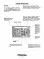
CAPTAIN CONTROL PANEL
DESCRIPTION
The panel also includes an a1ann buzzer for low OIL
PRESSURE or high COOLANT TEMPERATURE. The
RPM gauge is illuminated when the KEY switch is turned on
and remains illuminated while the engine is in operation.
This manually-operated control panel is equipped with a
KEY switch, an RPM gauge, PREHEAT and START buttons, an INSTRUMENT TEST button and three indicator
lamps, one for ALTERNKfOR DISCHARGE, one for low
OIL PRESSURE, and one for high ENGINE COOLANT
1EMPERATURE.
ALARM: THE ALARM WILL SOUND IF THE ENGINE"S OIL PRESSURE FALLS
BELOW 5 -10 psi (0.4- 0.7 kg/em'). IN THIS EVENT, THE ALARM WILL EMIT A
PULSATING SIGNAL. THE ALARM WILL ALSO SOUND IF THE COOLANT
TEMPERATURE IN THE FRESHWATER COOLING CIRCUIT RISES TO
21 o•f (99.C). IN THIS EVENT, THE ALARM WILL EMIT A CONTINUOUS SIGNAL.
NOTE: THE ALARM WILL SOUND WHEN THE KEY SWITCH IS TURNED ON. THIS
SOUNDING IS NORMAL. ONCE THE ENGINE STARTS AND THE ENGINFS OIL
PRESSURE REACHES 15 psi (1.1 k'g/cm'), THE ALARM WILL SILENCE.
RPM GAUGE: REGISTERS REVOLUTIONS
PER MINUTE OF THE ENGINE AND CAN BE
RECALIBRATED FOR ACCURACY FROM
THE REAR OF THE PANEL.
OIL PRESSURE
ALARM LIGHT
ALTERNATOR
ALARM LIGHT
TEST BUTTON: WHEN
PRESSED, TESTS THE
ALTERNATOR, THE OIL
PRESSURE, AND THE
COOLANT TEMPERATURE CONTROL CIRCUITS. WHEN PRESSED,
THE ALTERNATOR, THE
OIL PRESSURE, AND
THE WATER TEMPERATURE INDICATOR
LIGHTS ILLUMINATE IN
ADDITION TO SOUNDING THE ALARM
BUZZER.
- - - - KEY SWITCH: PROVIDES
POWER ONLY TO THE
INSTRUMENT PANEL
CLUSTER.
WATER TEMPERATURE
ALARM LIGHT
START BUTTON: WHEN PRESSED, ENERGIZES THE
STARTER'S SOLENOID WHICH CRANKS THE ENGINE. THIS
BUTTON WILL NOT OPERATE ELECTRICALLY UNLESS THE
PREHEAT BUTTON IS PRESSED AND HELD AT THE SAME
TIME.
7
PREHEAT BUTTON: WHEN PRESSED, ENERGIZES THE
ALTERNATOR'S EXCITER, THE FUEL LIFT PUMP, THE FUEL
SOLENOID ON THE INJECTION PUMP, AND THE ENGINE'S
GLOW PLUGS, AND BYPASSES THE ENGINE'S OIL PRESSURE ALARM SWITCH. IN ADDITION, THIS BUTTON ENERGIZES THE START BUTTON.
PREPARATIONS FOR INITIAL START-UP
NOTE: If the engine has not yet been filled with coolant,
PRESTART INSPECTION
refer to the COOUNG SYSTEM section of this manual.
Before starting your engine for the first time or after a
prolonged layoff, check the following items:
0
Visually examine the engine. Look for loose or missing
parts, disconnected wires, and unattached hoses. Check
the threaded connections and engine attachments.
0
Check the engine oil level. Add oil to maintain the level
at the high mark on the dipstick.
0
Tum on the fuel supply, then check the fuel supply and
examine the fuel filter/water separator bowl for
contaminants.
D Make certain there is proper ventilation around the
0
0
Check the transmission fluid level.
0
0
Make sure the mounting installation is secure.
Ensure the propeller shaft is securely attached to the
transmission.
0
Open the thru-hull and make certain raw water is primed
to the raw water strainer.
0
engine. An ample supply is necessary for proper engine
performance.
Check the DC electrical system. Inspect wire connections
and battery cable connections. Make certain the positive
(+) battery cable is connected to the starter solenoid and
the negative(-) cable is connected to the engine ground
stud (this location is tagged).
Check the coolant level in both the plastic recovery tank
and at the manifold.
CHECK ENGINE
OIL LEVEL
DIPSTICK
FULL
LOW
CHECK COOLANT LEVEL
Engines & Generators
8
STARTING/STOPPING PROCEDURE
CHECK LIST
FAILURE TO START
Follow this check list each day before sta1ting your engine.
If the engine fails to start when the start button is pressed for
5 seconds, wait for at least 30 seconds and repeatthe starting
procedure. Make certain the transmission control is in the
neutral position.
0 Visually inspect the engine for fuel, oil, or water leaks.
D Check the oil level (dipstick).
D Check the coolant level in the coolant recovery tank.
Never run the starter motor for more than 30 seconds. If the
engine fails to start, refer to the TROUBLESHOOTING
CHART in this manual.
Periodically check the manifold coolant level.
D Check the transmission fluid level.
D Check your fuel supply.
D .Look for clean fuel in the fuel filter/water separator
D
A CAUTION: Prolonged cranking intervals without the
transparent bowl.
Check for loose wires at the alternator and make sure its
mounting is secure.
engine starting can result in the engine exhaust system
filling with raw water. This may happen because the
pump is pumping raw water through the raw water
cooling system during cranking. This raw water can
enter the engine's cylinders by way of the exhaust
manifold once the exhaust system fills. Prevent this
from happening by closing the raw water supply
through-hull shut-off, draining the exhaust muffler, and
correcting the cause of the excessive engine cranking.
Engine damage resulting from raw water entry is not a
warrantable issue; the owner/operator should keep this
in mind.
D Check the starting batteries (weekly).
D Check drive belts for wear and proper tension (weekly).
D Check the raw water pump to make sure its mounting is
secure.
STARTING THE ENGINE
1. Put the transmission in neutral and advance the throttle.
2. Turn the KEY to the ON position (2 o'clock).
(The panel is energized, gauges are lit).
3. Depress the PREHEAT BUTTON, hold for 5 to 15
seconds depending on how cold it is.
(The fuel lift pump is priming the engine and the preheat
is activated).
4. Continue pressing the PREHEAT BUTTON and press
the START BUTTON.
(The start motor is cranking the engine).
5. Release the START BUTTON as the engine starts.
6. With the engine running, check the instruments for
proper oil pressure and battery charging voltage. Also
check for overboard discharge of exhaust water. The
water temperature will rise slowly until the thermostat
opens. Do not engage the gear shift until the temperature
is close to normal.
STOPPING PROCEDURES
To stop the engine, bring the throttle to an idle position and
place the transmission in neutral. Allow the engine to idle for
a few moments to stabilize the engine temperature. Then pull
the shut-off tee/knob out and allow the engine to stop fully.
Then push the shut-off tee/knob back in fully and shut-off
with key.
NOTE: Units with the Optional Electric Shut-Off, just tum off
the key.
FAILURE TO STOP (Optional Electric Shut·Off)
In the unusual situation that the key switch fails to tum the
engine off and it stays at a low idle, shut down can be
accomplished by manually working the shut off lever located
adjacent to the throttle lever by the injection pump.
NOTE: Never attempt to engage the starter while the
engine is running.
NOTE: In such cases the electric fuel shut off solenoid
may need to be threaded into the block an additional
It is important to closely monitor the panel gauges.
become aware of the normal-engine readings and take
immediate action if these readings start to vary.
Y4- ~turn.
If a "smart" regulator is part of the charging system,
allow about 50 seconds for the RPM gauge to activate.
NOTE: When starting:
A voltage drop will occur
when the preheat·switch
is depressed.
9
~:
ENGINE BREAK-IN PROCEDURE
DESCRIPTION
3. While using the vessel, run the engine at various engine
speeds for the first 25 hours. Avoid prolonged periods of
idling.
4. Avoid rapid acceleration, especially with a cold engine.
Although your engine has experienced a minimum of one
hour of test operations at the factory to make sure accurate
assembly procedures were followed and that the engine operated properly, a break-in time is required. The service life of
your engine is dependent upon how the engine is operated
and serviced during its initial 50 hours of use.
5. Use caution not to overload the engine. The presence of a
grey or black exhaust and the inability of the engine to
reach its full rated speed are signs of an overload.
Breaking-in a new engine basically involves seating the piston rings to the cylinder walls. Excessive oil consumption
and smoky operation indicate that the cylinder walls are
scored, which is caused by overloading the engine during the
break-in period.
•6. During the next 25 hours, the engine may be operated at
varying engine speeds, with short runs at full rated rpm.
Avoid prolonged idling during this break-in period.
CHECK LIST
D Monitor the control panel gauges.
D . Check for leaks of fuel and engine oil.
Your new engine requires approximately 50 hours of initial
conditioning operation to break in each moving part in order
to maximize the performance and service life of the engine.
Perfonn this conditioning carefully, keeping in mind the following:
1. Start the engine according to the STARTING PROCEDURE section. Run the engine at fast idle while checking
that all systems (raw water pump, oil pressure, battery
charging) are functioning.
0
Check for abnormal noise such as knocking, friction,
vibration and blow-back sounds.
0
Confirm exhaust smoke:
When the engine is cold - white smoke.
When the engine is wru.m - almost smokeless.
When the engine is overloaded - some black smoke and soot
NOTE: See the TRANSMISSION section of this manual for
break-in information on your transmission.
2. Allow the engine to warm up (preferably by running at
fast idle) until the water temperature gauge moves into
the 130- 140°F (55- 60°C) range.
Engines & Generators
10
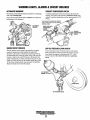
WARNING LIGHTS, ALARMS &CIRCUIT BREAKER
ALTERNATOR WARNINGS
COOLANT TEMPERATURE SWITCH
The Captain Control Panel indicates alternator low discharge
with a red warning light.
The Admiral Control Panel uses a voltmeter to monitor the
performance of the alternator.
A coolant temperature switch is located on the thermostat
housing. This switch will activate a continuous alarmifthe
coolant's operating temperature reaches approximately :?l0°f.
(99°C).
THIS COOLANT TEMPERATURE SENDOR
IS ONLY AVAILABLE WITH THE ADMIRAL .
. CON_TROL PANEL
WATER (COOLANT)
TEMPERATURE· .
· SENDER '
(OPTIONAL)
ENGINE CIRCUIT BREAKER
LOW OIL PRESSURE ALARM SWITCH
The DC harness on the engine is protected by an engine
mounted manual reset circuit breaker (20 amps DC).
Excessive current draw or electrical overload anywhere in
the instrument panel wiring or engine wiring will cause the
breaker to trip. In this event DC power to the electric fuel
pump will terminate. As fuel is consumed and runs out, the
engine will slow and stop. If this breaker should trip, check
for the cause of high current draw and repair the problem.
Reset the bre.aker and re-start the engine.
A low oil pressure alarm switch is located on the engine
block. This switch's sensor monitors the engine's oil pressure. Should the engine's oil pressure fall to 5 - 10 psi
(0.4-0.7 kg/cm2), this switch will activate a pulsating
alarm.
OIL PRESSURE SWITCH
Engines & Generators
11
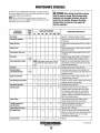
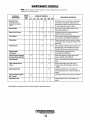
MAINTENANCE SCHEDULE
In order to use this Maintenance Schedule, it will be necessary
to log your engine hours. Use your engine hourmeter or record
your engine hours by rmming time.
NOTE: Many of the following maintenance procedures are
simple but others are more difficult and may require the expert
knowledge of a service mechanic.
SCHEDULED
MAINTENANCE
CHECK
EACH
DAY
A WARNING: Never attempt to perform any service
while the engine is running. Wear the proper safety
equipment such as goggles and gloves, and use the
correct tools for each job. Disconnect the battery
terminals when servicing any of the engine's DC
electrical equipment.
HOURS OF OPERATION
50
100
250
500
MAINTENANCE DESCRIPTION
750 1000 1250
Filter/Water Separator
D
D
Engine Oil Level
D
Oil level should indicate between MAX. and LOW on
dipstick.
Coolant Level
D
Check at recovery tank; if empty, check at manifold.
Add coolant if needed.
Transmission Fluid Level
D
Fluid level should indicate between MAX and LOW
on dipstick.
D
Inspect for proper tension (3/8" to 1/2" deflection)
and adjust if needed. Check belt edges for wear.
Fuel Supply
Drive Belts
Diesel No. 2 rating of 45 cetane or higher.
Check for water and dirt in fuel (drain/replace filter
if necessary).
weekly
Visual Inspection of Engine
D
NOTE: Keep engine surface clean. Dirt and
oil will inhibit the engine's ability to remain
cool.
D
Fuel Filter
Starting Batteries
(and House Batteries)
D
D
D
D
D
D
Check for fuel, oil and water leaks. Inspect wiring
and electrical connections. Keep bolts & nuts tight.
Check for loose belt tension.
Change at 50 hours then every 250 hours.
Check electrolyte levels every 50 operating hours
and make sure connections are very tight. Clean off
excessive corrosion.
weekly
Engine Oil and Filter
D
D
D
D
D
D
D
Initial engine oil & filter change at 50 hours, then
change both every 100 hours.
Heat Exchanger Zinc Anode
D
D
D
D
D
D
D
Inspect zinc anode, replace if needed. Clear the heat
exchanger end of zinc anode debris.
D
D
D
D
D
D
D
D
D
Change filter every 200 hours.
D
D
D
D
Filter/Water Separator
Exhaust System
D
D
Engine Hoses
Throttle Transmission
Shut-Off Cables
D
Adjust Engine Idle Speed
D
D
D
Initial check at 50 hours, then every 250 hours.
Inspect for leaks. Check anti-siphon valve operation. Check the exhaust elbow for carbon and/or
corrosion buildup on inside passages; clean and
replace as necessary. Check that all connections are
tigl1t. Check casting integrity.
D
Hose should be hard & tight. Replace if soft or
spongy. Check and tighten all hose clamps.
D
Check for loose fittings, cotter pins, etc.
Lubricate with WD-40 or equivalent.
Adjust to 1000 - 1200 rpm
Raw Water Pump
D
Inlet Fuel Filter
D
D
D
D
D
D
Remove the pump cover and inspect the impeller,
gasket, cam and cover for wear. Check the bearings
and seals (the shaft can turn, but not wobble).
Lubricate when reassembling.
D
Replace.
(continued)
12
MAINTENANCE SCHEDULE
NOTE: Use the engine hourmeter gauge to log your engine hours or record your
engine hours by running time.
SCHEDULED
MAINTENANCE
CHECK
EACH
DAY
HOURS OF OPERATION
50
100
250
500
MAINTENANCE DESCRIPTION
750 1000 1250
D
Raw Water Pump
Remove the pump from the engine. Disassemble
and inspect all components, replacing all worn
components as needed. Inspect the drive gear slot
for wear. Replace drive gear as needed.
At 750 operating hours,
disassemble and inspect for
overhaul.
D
Coolant System
Electric Fuel lift Pump
D
D
D
D
D
D
Drain, flush, and refill cooling system with the
appropriate antifreeze mix.
D
Periodically check the wiring connections and
inspect the fuel line connections.
D
*Fuel Injectors
Check and adjust injection opening pressure and
spray condition. (see ENGINE ADJUSTMENTS).
*Starter Motor
D
D
Check solenoid and motor for corrosion. Remove
and lubricate. Clean and lubricate the starter motor
pinion drive.
*Preheat Circuit
D
D
Check operation of preheat solenoid. Remove and
clean glow plugs, check resistance (4-6 ohms).
Reinstall with anti-seize compound on threads.
*Engine Cylinder
Compression
D
D
Check compression pressure and timing
(see ENGINE ADJUSTMENTS).
*Adjust the Valve Clearances
Re-torque Cylinder Head Bolts
D
D
*Heat Exchanger
D
*Water Injected Exhaust
Elbow
Engine Damper Plate
lubricate Panel Key Switch
with "lockeze"
D
Adjust Valve Clearances, re-torque cylinder head
bolts.( see ENGINE ADJUSTMENTS).
D
Remove, have professionally cleaned and pressure
tested.
D
Check casting integrity every 500 hours of
operation. Clean internal passage. Replace as
needed.
D
Chattering at idle/low rprn is an indication of
damper plate spring wear. Inspect and replace as
needed.
D
Lubricate at 50 hours, then at least once a season.
D
Transmission Fluid
*WESTERBEKE recommends this service be performed by an authorized mechanic.
13
Initial change at 25 hours, then at least once a
season.
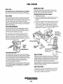
FUEL SYSTEM
ENGINE FUEL FILTER
DIESEL FUEL
Periodically check the fuel connections and the bowl for
leakage. Replace the filter element after the first 50 hours
then follow the MAINTENANCE SCHEDULE.
USE A DIESEL FUEL WITH A CETANE RATING OF #45 OR HIGHER.
(No. 2-0 (SAE J313) diesel fuel according to ASTM 0975).
Changing/cleaning the filter element
FUEL FILTERS
1. Shut off the fuel supply.
The fuel injection pump and the fuel injectors are precisely
manufactured and they must receive clean diesel fuel, free
from water and dirt. To ensure this flow of clean fuel, the fuel
must pass through at least two fuel filters, a fuel water
separator and the engine's spin-on fuel filter. Visually inspect,
clean, and change these filters according to the maintenance
schedule in this manual.
2. Unscrew the retainer ring that holds the filter bowl to the
housing and allow the bowl to coine away from the
housing,
3. Remove and replace the filter element and clean the bowl.
4. Replace the sealing "0" ring and reassemble the bowl
to the housing. Thread the retainer ring on carefully
so as not to cross thread. When retainer contacts the
"0" ring, tighten 114 - 112 turns by hand. Open the fuel
gum!y and run the engine to inspect for leaks.
FUEL WATER SEPARATOR
A primary fuel filter of the water separating type must be
installed between the fuel tank and the engine to remove
water and other contaminants from the fuel before they can
be carried to the fuel system on the engine.
LIGHTLY WIPE
WITH CLEAN FUEL
WHEN INSTALLING
THE NEW FUEL
FILTER CARTRIDGE
The owner/operator is responsible for making certain the
fuel reaching the engine's injection equipment is free of
impurities. This process is accomplished by installing and
maintaining a proper fuel filter/water separator between the
fuel tank and the generator/engine. Westerbeke recommends a
10 micron (no finer) filter be used .
.-IJ'i I
FUEL LIFT PUMP
TYPICAL
FUEL
FILTER
INLET FUEL·
FILTER
THE 0-RING GASKET~~W:
ONLY NEEDS TO BE
REPLACED IF IT
SIGNS OF AGING.
(OWNER INSTALLED)
FUEL LIFT PUMP
The fuel injection pump is the most important component
of the diesel engine, requiring the utmost caution in handling.
The fuel injection pump has been thoroughly bench-tested
and the owner/operator is cautioned not to attempt to service
it. If it requires servicing, remove it and take it to an
authorized fuel injection pump service facility. Do not
attempt to disassembly and repair it.
The only adjustment the servicing mechanic should make to
the fuel injection pump is the adjustment for the engine idle
speed (see IDLE SPEED ADJUSTMENT under ENGINE
ADJUSTMENTS).
Periodically check the fuel connections to and out of the pump
and make sure that no leakage is present and that the fittings
are tight and secure. The DC ground connection at one of the
pump's mounting bolts should be clean and well secured by
the mounting bolt to ensure proper pump operation.
When energized thru the preheat circuit, the fuel lift pump will
purge air from the fuel system and provide· a continuous flow
of fuel as the engine is running.
INLET FUEL FILTER
To ensure clean fuel into the fuel pump, there is a small inline fuel filter connected to the fuel lift pump elbow. This
filter should be replaced every 250 hours of operation or
once a season, which ever occurs first.
14
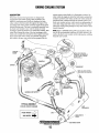
ENGINE COOLING SYSTEM
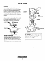
DESCRIPTION
Westcrbeke marine diesel gen.erators are designed and
equipped for fresh water cooling. Heat produced in the
engine by combustion and friction is transferred to fresh
water coolant which circulates throughout the engine. This
circulating fresh water coolant cools the engine block and its
internal nmving parts. The heat is transferred externally from
the fresh water coolant to raw water by means of a heat
exchanger; similar in function to an automotive radiator. Raw
water flows through the tubes of the heat exchanger while
fresh water coolant flows around the tubes; engine heat transferred to the fresh water coolant is conducted through the
tube wa1ls to the raw water which is then pumped into the
exhaust system where finally it is discharged overboard. In
other words, the engine is cooled by fresh water coolant, this
coolant is cooled by raw water, and the raw water carries the
transferred heat overboard through the exhaust system. The
fresh water coolant and raw water circuits are independent of
each other. Using only fresh water coolant within the engine
allows the cooling water passages to stay clean and free from
harmful deposits.
NOTE: Refer to ENGINE COOLANT paragraphs in this section for the recommended antifreeze and water mixture to be
used as the fresh water coolant and for information on filling
the fresh water system.
/-.......____,
"-.....
EXHAUST
ELBOW
NOTE: KEEP PASSAGE
THROUGH THE MANIFOLD
CLEAR (A PIPE CLEANER
WORKS WELL).
EXHAUST
'
~ NOTE: AN ANTI-SIPHON
, VALVE MAY BE REQUIRED
\
TYPICAL ASSEMBLY
COOLING CIRCUIT DIAGRAM
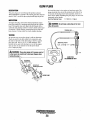
FRESH WATER
RAWWATER
¢
~
RAW WATER DRAIN
15
COOLING SYSTEM
FRESH WATER COOLING CIRCUIT
Fresh water coolant is pumped through the engine by a
circulating pump, absorbing heat from the engine. The
coolant then passes through the thermostat into the manifold,
to the heat exchanger where it is cooled and returned to the
engine block via the suction side of the circulating pump.
When the engine is started cold, extemal coolant flow is
prevented by the closed thermostat (although some coolant
flow is bypassed around the thermostat to prevent th~ exhaust
manifold from overheating). As the engine warms up, the
thermostat gradually opens, allowing full flow of the engine's
coolant to flow unrestricted to the external portion of the
cooling system.
NOTE: Periodically check the condition of the pressure cap.
Ensure that the upper and lower rubber seals are in good
condition and check that the vacuum valve opens and closes
tightly. Carry a spare cap.
CHANGING COOLANT
ENGINE COOLANT
The engine's coolant must be changed according to the
MAINTENANCE SCHEDULE. If the coolant is allowed to
become contaminated, it can lead to overheating problems.
Drain the engine coolant by removing the block drain adjacent to the oil filter, remove the in-board drain plug on the
heat exchanger and remove the pressure cap from the water
jacketed exhaust manifold.
WESTERBEKE recommends a mixture of 50% antifreeze
and 50% distilled water. Distilled water is free from the
chemicals that can corrode internal engine surfaces.
The antifreeze performs a double duty. It allows the engine
to run at proper temperatures by transferring heat away from
the engine to the coolant and lubricates and protects the
cooling circuit from rust and corrosion. Look for a good
quality antifreeze that contains Supplemental Cooling
Additives (SCAs) that keep the antifreeze chemically balanced, crucial to long term protection.
NOTE: Look for the new environmentally friendly long lasting
antifreeze that is now available.
The recommended 50/50 mixture will protect the engine
against the most extreme temperature. The antifreeze mixture
will also retard rust within the engine and add to the life of
the circulating pump impeller and seals.
Refilling the Coolant
A proper 50/50 mixture as recommended will protect the
engine coolant to temperatures of- 40°F.
After closing the engine drains, pour clean, premixed coolant
into the manifold, start the engine and run it at a slow idle.
Monitor the coolant in the manifold and add as needed. Fill
the manifold to the filler neck and when the coolant is
flowing, install the pressure cap.
Remove the cap on the coolant recovery tank and fill with
coolant mix to halfway between LOW and MAX and replace
the cap. Run the engine and observe the coolant expansion
flow into the recovery tank.
After checking for leaks, stop the engine and allow it to cool.
Coolant should draw back into the cooling system as the
engine cools down. Add coolant to the recovery tank if
needed. Clean up any spilled coolant
Coolant Recovery Tank
A CAUTION: The engine must be allowed to cool
The coolant recovery tank allows for the expansion and contraction of the engines coolant during engine operation without introducing air into the system. This recovery tank is
provided with fresh water cooled models and with the fresh
water coolant conversion kit and must be installed before
operating the engine.
down before attempting these procedures. Not only is
the surface of the engine hot but coolant temperatures
can be at 19lf F.
A CAUTION: Proper cooling system maintenance is
NOTE: This tank, with its short nm of plastic hose, is best
critical; a substantial number of engine failures can be
traced back·to cooling system corrosion.
located at or above the level of the engines manifold.
16
COOLING SYSTEM
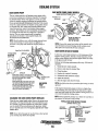
THERMOSTAT
A thermostat, located near the manifold at the front of the
engine, controls the coolant temperature as the coolant
continuously flows through the closed cooling circuit. When
the engine is first started, the closed thermostat prevents
coolant from flowing (some coolant is by-passed through a
hole in the thennostat to prevent the exhaust manifold from
overheating). As the engine wanns up, the thermostat
gradually opens. The thermostat is accessible and can be
checked, cleaned, or replaced easily. Carry a spare thermostat
and gasket
THERMOSTAT
ASSEMBLY
GASKET
SEAL WITH HI-TACK
A coolant recovery tank allows for engine coolant expansion
and contraction during engine operation, without any significant loss of coolant and without introducing air into the cool·
ing system. This tank should be located at or above the
engine manifold level and should be easily accessible.
TO COOLANT
RECOVERY TANK
KEEP THE
COOLANT PASSAGE
CLEAR
FROM COOLANT
RECOVERY TANK
COOLANT EXPANSION
WATER TEMPERATURE
SWITCH
PRESSURE
/CAP
COOLANT RETRACTION
A CAUTION: The engine must be allowed to cool
Replacing the Thermostat
down before attempting these procedures. Not only
is the surface of the engine hot but coolant
temperatures can be at 190° F.
Remove the cap screws and disassemble the thermostat
housing as shown. When installing the new thermostat and
gasket, apply a thin coat of sealant on both sides of the
gasket before pressing it into place. Do not over-tighten the
cap screws.
Run the engine and check for normal temperatures and that
there are no leaks at the thermostat housing.
Engines & Generators
17
COOLING SYSTEM
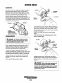
RAW WATER PUMP (EARLY MODELS)
RAW WATER PUMP
The raw water pump is a,self-priming; rotary pump with a
non-ferrous housing and a Neoprene impeller. The impeller
has flexible blades which wipe against a curved cam plate
within the impeller housing, producing the pumping action.
On no account should this pump be run dry. There should
always be a spare impeller and impeller cover gasket aboard
(an impeller kit). Raw water pump impeller failures occur
when lubricant (raw water) is not present during engine
operation. Such failu:t;eS are not warrantable, and operators
are cautioned to make sure raw water flow is present at
start-up. The raw water pump should be inspeCted
peripdically for broken or tom impeller blades. See
MAiNTENANCE S9HEDULE.
·
SAME INSTRUCTIONS APPLY .
·
Impeller Kit
#034440
ALIGN· THE IMPELLER
SCREW WITH THE
· SLOT IN THE SHAFT
NOTE: Shoulcl a failure occur with the pumps internal parts
(seals and bearings), it may be more cost efficient to
p!fri::hase a new pump and rebuild the original pump as
·a spare.
NOTE: lfany of ~he vanes have broken off the impeller th'ey
must be found to'jm!vent blockage in the cooling circuit.
They ofte~ can be found i~ the heat exchanger.
Impeller Kit #048500
RAW WATER INTAKE STRAINER
A clean raw water intake strainer is a vital component of the
IMPELLER ..
INSPECTION: CHECK AT THE BASE OF.
. EACH BLADE BY BENDING VIGOROUSLY.
· REPLACE THE IMPELLER IF THERE
.
ARE ANY CRACKS.. .
WHEN INSTALI.fNG: TAKE CARE TO ALIGN
THE IMPELLER KEYWAY WITH THE SHAFT
KEY. FOLD THE IMPELLER. BLADES IN
EITHER DIRECTION (THEY WILL TURN IN
THE CORRECT POSITION WHEN THE
IMPELLER STARTS TO ROTATE).
engine's cooling sys&m1:. Include a visual inspection of this .
strainer when making your periodic engine check. The water
in the glass should be clear.
Perfonn the following :tnaintenance after every 100 ho.urs' of
operation: ·
·
.
1. Close the raw water seacoclc. ·
2. Remove and clean the strainer filter.
3. Clean the glass.
· 4. Replace the washer if necessary.
5. Reassemble and install the strainer.
6. Open the seacock.
7•. Run the engine and check for leaks.
RAWWAlER
PUMP
#048080
NOTE: Also follow tlte above procedure after having run harrl
aground.
H the engine temperature gauge ever shows a higher than
nonnal reading, the cause may be that silt, leaves or grass
may have been ('.aught up in the strainer, slowing the flow of
raw water through the cooling system.
NOTE: Always install the strainer at or belo~ the waterline so
CHANGING THE RAW WATER PUMP IMPELLER
the strainer will always be self-priming.
Close the raw water intake valve. Remove the pump cover
TYPICAL RAW WATER INTAKE STRAINER
and gasket or 0-ring with the aid of two screwdrivers or pli·
ers. Carefully pry/pull the impeller out of the pump. Lightly
coat the inside of the pump housing with glycerine. InstaU
the new impeller and cover with gasket, open the raw water
intake valve.
(OWNER INSTALLED) ·
NOTE: Never allow the pump to run dry. Even a short period
of dry running may destroy the impeller.
Eng!f!fl.~~~.:.o~IJnerators
18
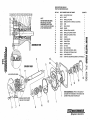
REPAIR PARTS ARE AVAILABlE
FROM YOUR WESTERBEKE DEALER
NOTE
THE PUMP-flEPAIR KIT (49000)
INCLUDES ALL THE LISTED
COMPONENTS EXCEPT ITEMS
1 AND 7._THE KiT ALSO INCLUDES
A PUMP MOUNTING GASKET.
KEY NO.
PART NUMBER AND PART NAME
1
2
3
4
5
6
7
8
48080
49172
49170
48500
34458
49171
302575
48253
34463
48359
33041
33037
46662
48254
49169
34464 .
33045
33044 ·
49000
37431
9
10
11
12
13
ASSEMBLED VIEW
14'
15
16
17
18
.....
~~
~(I)
RAW WATER PUMP
SHAFT
IMPELLER COVER
IMflELI:.ER KIT (0-RING & GLYCERIN) .
CAM
WEAR PLATE
DOWEL
SPRING SEAL WASHER
IMPELLER COVER SCREW
IMPELLER COVER 0-RING
o:RING
CAM WASHER
CAM SCREW
SPRING SEAL
LIP SEAL
BALL BEARING
RETAINING INTERNAL RING
RETAINING EXTERNAL RING
PUMP REPAIR KIT
PUMP KIT (MOUNTING GASKET & FITTINGS)
1
>C')SI
!g ...
CD=
1
....
~
1·-m
1:a
.1, .~
-
-u
z
....
~
c::o
0
c::o
ALIGN.SLOTINTODOWEL ~
I
i
/
16
I
I
APPLY
:a
.,==·
EXPLODED VIEW
~~
6
1
1
1
1
1
·!, ~
2
CORo~
~
QUANITY
·/
\"'7
WHEN ASSEMBliNG: APPLY A THIN COATOF
GLYCERIN TO THE INSIDE OF THE COVER, THE
COVER 0-RING, AND THE IMPELLER
IMPELLER PIN FITS INTO .
THE SLOT IN THE SHAFT
9
Engines & Generators
0
COOLING SYSTEM
Zinc Anode #011885
If the zinc anodes need replacement, hold the hex boss into
which the zinc anode is threaded with a wrench while loosening the anode with another wrench. This prevents the hex
boss from possibly tearing off the exchanger shell. After
removing the Zinc, note the condition of it. If the zinc is in
poor condition, there are probably· a lot of zinc flakes within
the exchanger. Remove the end of the heat exchanger and
clean the inside of all zinc debris. Always have a spare heat
exchanger end gasket in case the present one becomes damaged when removing the end cover. Replace the gasket (refer
to your engine model's heat exchanger end gasket part number), 0-ring and cover, and install a new zinc anode.
A zinc anode, or pencil, is located in the raw water cooling
circuit within the heat exchanger. The purpose of having the
zinc anode is to sacrifice them to electrolysis action taijng
place in the raw water cooling circuit, thereby reducing the
effects of electrolysis on other components of the system.
The condition of the zinc anode should be checked monthly
and the anode cleaned or replaced as required: Spare anodes
should be carried on board.
NOTE: The threads of the zinc anodes are pipe threads and
do .not require sealant. Sealant should not be used as it may
insulate the zinc from the metal ofthe heat exchanger housing preventing electrolysis action on the zinc.
Heat Exchanger Service .
NEW_
REPLACE
REPLACE
After approximately 1000 hours of operation, remove, clean
and pressure test the engine's heat exchanger. (A local automotive radiator shop should be able to clean and test the heat
exchanger.)
CLEAN AND
REUSE
ZINC ANODES
NOTE: Operating in silty and/or tropical waters may require
that a heat exchanger cleaning be performed more often than
every 1000 hours.
NOTE: Electrolysis action is the result of each particuidr
installation and vessel location; not that of the engine.
HEAT EXCHANGER
ZINC ANODE
DO NOT USE SEALANT
ON THE THREADS
-ANTIFREEZE
COOLANT
•DRAIN
(PETCOCK OR HEX PLUG)
COVER
SECURING
BOLT
WATER
INSPECT
BOTH ENDS
CLEAN OUT EVERY 'DRAIN
tOO HOURS
CLEAN OUT DEBRiS
TYPICAL ASSEMBLY
NOTE: When installing the heat exchanger end covers. Be
~ure that the end cover securing bolt's sealing 0-ring is
installed. Failure to install this- sealing 0-ring can result in
end plate failure/sea water leakage.
Engines & Generators
19
ENGINE LUBRICATING OIL
2. Replacing the Oil Filter. When removing the used oil
filter, you may find it helpful and cleaner to punch a hole
. in the upper and lower portion of the old filter to drain the
oil from it into a container before removing it. This helps
to lessen spillage. A small style automotive filter wrench
should be helpful in removing the old oil filter.
NOTE: Do not punch this hole without first loosening the
filter to make certain it can be removed!
Place some paper towels and a plastic bag around the
filter when unscrewing it to catch any oil left in the filter.
(Oil or any other fluid on the engine reduces the engine's
cooling ability. Please keep your engine clean.) Inspect the
old oil filter as it is removed to make sure that the rubber
sealing gasket came off with the old oil filter. If this
rubber sealing gasket remains sealed against the engine
block, g((ntly remove it.
ENGINE OIL CHANGE
1. Draining the Oil Sump. Discharge the used oil through
the sump drain hose (attached to the front of the engine)
while the engine is warm. Drain the used oil completely,
replace the hose in its bracket, and replace the end cap
securely.
NOTE: Thread size for the lube oil drain hose capped end
is 114 NPT.
When installing the new oil filter element, wipe the filter
gasket's sealing surface on the engine block free of oil and
apply a thin coat of clean engine oil to the rubber gasket
on the new oil filter. Screw the filter onto the threaded oil
filter nipple, and then tighten the filter firmly by hand.
NOTE: Generic filters are not recommended, as the
material standards or diameters of important items on
generic parts might be entirely different from genuine
parts. Immediately after an oil filter change and oil fill,
run the engine to make sure the oil pressure is normal and
that there are no oil leaks around the new oil filter.
A WARNING: Used engine oil contains harmful
contaminants. Avoid prolonged skin contact. Clean skin
and nails thoroughly using soap and water. Launder or
discard clothing or rags containing used oil. Discard
used oil properly.
3. Filling the Oil Sump. Add new oil through the oil filler
cap on the top of the engine. After refilling, run the
engine for a few moments while checking the oil
pressure. Make sure there is no leakage around the new
oil filter or from the oil drain system, and stop the engine.
Then check the quantity of oil with the lube oil dipstick.
Fill to, but not over the high mark on the dipstick, should
the engine require additional oil.
20
REMOTE OIL FILTER (OPTIONAL)
PN# 040078
INSTALLATION
This popular accessory is used to relocate the engine's oil filter from the engine to a more convenient location such as an
engine room bulkhead.
NOTE: Westerbeke is not responsible for engine failure due to
incorrect installation of the Remote Oil Filter.
.
A CAUTION: It is vital to install the oil lines
NOTE: Refer to ENGINE OIL CHANGE in this manual for
instructions on removing the oil filter.
correctly. If the oil flows in the reverse direction, the
by-pass valve in the filter assembly will prevent the oil
from reaching the engine causing an internal engine
failure. If there is no oil pressure reading, shutdown
imediately and check the hose cnnnections.
To install, simply remove the engine oil filter and thread on
WESTERBEKE's remote oil filter kit as shown. Always
install this kit with the oil filter facing down as illustrated.
Contact your WESTERBEKE dealer for more information.
APPLY A THIN COAT OF CLEAN OIL TO THE 0-RING WHEN
INSTALLING THIS KIT. THREAD THE KIT ON, THEN HAND
TIGHTEN AN ADDITIONAL 3/4 TURN AFTER THE 0-RING
CONTACTS THE BASE.
THE IN CONNECTION HOSE
MUST ATTACH TO THE OUT
CONNECTION AT THE
~~-- R~NtnT~ OIL FILTER.
THE OUT CONNECTION HOS
MUST ATTACH TO TilE IN
CONNECTION ATTHE
REMOTE OIL FILTER.
APPLY A THIN COAT OF CLEAN OIL TO THE FILTER
GASKET WHEN INSTALLING. AFTER THE FILTER
CONTACTS THE BASE, TIGHTEN IT AN ADDITIONAL
21'
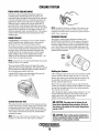
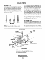
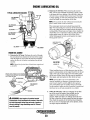
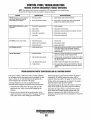
DOMESTIC HOT WATER TANK CONNECTIONS
DESCRIPTION
PREVIOUS MODEL ENGINES
Both the two and three cylinder models are equipped with
connections to send engine coolant to a domestic water heater.
If the owner/operator wishes to connect a water heater, remove
the bypass hose and connect a water heater as described in
the instructions presented below .
REMOVE THE
BY-PASS HOSE
HEATER BELOW ENGINE
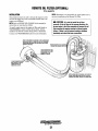
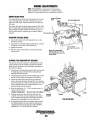
. CURRENT MODEL ENGINES
SIMPLY CUT INTO THE EXISTING HOSE AT THE THERMOSTAT HOUSING
AND INSERT TWO CONNECTORS (PART #302391) INTO THE TWO PIECES
OF HOSE COUPLE THE HOSES FROM THE WATER TANK TO THE OTHER
END OF THE CONNECTORS AND TIGHTEN THE HOSE CLAMPS. IT WILL NOT
MATTER WHICH HOSES RUN TO AND FROM THE TANK.
HEATER COILS BELOW
PRESSURE CAP ON ENGINE
MANIFOLD
With the bypass hose removed, there remain two connecting
points A and B for hoses to run to and from the water heater.
These connections assure a flow of hot water through the
heater at all times but do not restrict the engine's cooling
water.
Connection point A on the Flow Control housing should
connect to the lower of the two connections on the water
heater while the upper connection on the heater returns to
connection B, nearest the heat exchanger.
Hoses should rise continuously from their low point at the
heater to the engine so that trapped air will rise naturally
from the heater to the engine. If trapped air is able to rise to
the heater, then an air bleed petcock must be installed at the
higher fitting on the heater for bleeding air while filling the
system. Avoid loops in the hose runs which will trap air.
CONNECTOR
#302391
INSTALLATION
The heater should be mounted conveniently either in a
high or low position in relation to the engine, so that the
connecting hoses from the heater to the engine can run in a
reasonably direct line without any loops which might trap air.
(CONT.) HEATER ABOVE THE ENGINE
22
DOMESTIC HOT WATER TANK CONNECTIONS
HOT WATER HEATER ABOVE THE ENGINE
If any portion of the heating circuit rises above the engine's
own pressure cap, the a pressurized (aluminum) remote
expansion tank must be installed in the circuit to become the
highest point. The remote expansion tanks part number is
24177. Tee the remote expansion tank into the heater circuit
at the heater connection, choosing the higher of the two for
the return. Tee right at the heater and plumb a single line up
to the tanks location and the other back to the engine's flow
control. Install the remote expansion tank in a convenient
location such as in a sail locker so the fresh water coolant
level can easily be checked. The remote expansion tank will
now serve as a check and system fill point. The plastic
coolant recovery tank is not used when the remote expansion
tank kit is installed, since this tank serves the same function.
PRESSURE CAP IS RATED
LOWER THAN MANIFOLD CAP
HEATER COILS ABOVE
PRESSURE CAP ON ENGINE MANIFOLD
The pressure cap on the engine's manifold should be
installed once the engine's cooling system is filled with
coolant. Finish filling the cooling system from the remote
tallk once the system is filled and is free of air and exhibits
good coolant circulation. During engine operation, checking
the engine's coolant should be done at the remote tank and
not at the engine manifold cap.
The hose connection from the heater to the remote
expansion tank should be routed and supported so as to rise
continuously from the heater to the tank, enabling any air in
the system to rise.
J. '
.. \
REMOVE THE 8-~~~~-SS HOSE
~.)
23
I
I
HEATER ABOVE ENGINE
TACHOMETER
TACHOMETER/HOUR METER
NOTE: Current model tachometers use a coarse adjustment
dial to set the tachometer to the crankshaft pulley rpms. The
calibrating screw is then used for fine tuning.
The tachometer/hour meter used in propulsion engine
instrument panels contain two separate electrical circuits
with a common ground. One circuit operates the hour meter
and the other the tachometer. The hour meter circuit operates
on 12 volts alternator charging voltage supplied to the (+)
terminal on the back of the instrument.
LIGHT
The tachometer circuit operates on AC voltage 6-8 volts, fed
from one of the diodes in the alternator and supplied to the
tachometer input terminal while the engine is running, and
the alternator producing battery charging voltage 13.0-14.8
volts DC.
The following are procedures to follow when
troubleshooting a fault in either of the two circuits in a
tachometer/hour meter.
(+)TERMINAL
TAGH INP
AG VOLTAGE
CALIBRATION
Hour meter Inoperative
Check for the proper DC voltage between (+) and (-)
terminals.
1. Voltage present - meter is defective - repair or replace.
TACHOMETER CHECK (New Installation)
NOTE: In a new installation having new instrument panels,
2. Voltage not present - trace (+) and (-) electrical
connections for fault. (Jump 12 volts DC to meter (+)
tern1inal to velify the operation.)
the tachometer may not always be correctly calibrated to the
engine's rpm This calibration should be checked in all new
installations.
1. Warm up the engine to normal operating temperature.
Remove any specks on the crankshaft pulley with a clean
cloth and place a piece of suitable reflecting tape on the
pulley to facilitate use of a photoelectric type tachometer.
2. Start the engine, warm up, then set the engine speed
using the photo tach to 112 rated engine rated rpm.
3. Aim the light of the tachometer onto the reflecting tape to
confirm the engine speed. Check the instrument panel
tachometer reading. Adjust the tachometer in the panel by
using the instrument calibration pod as needed to bring
the instrument panel tachometer into the same rpm
reading as the engine.
4. Check the tachometer accuracy at idle and at rated rpm.
Adjust as needed.
Tachometer Inoperative
Check for the proper AC voltage between tachometer input
tern1inal and (-) terminal with the engine running.
1. Voltage present - attempt adjusting meter through
calibration access hole. No results, repair or replace
meter.
2. AC voltage not present - check for proper alternator DC
output voltage.
3. Check for AC voltage at tach terminal on alternator to
ground.
4. Check electrical connections from tachometer input
terminal to alternator connection.
Tachometer Sticking
l i
1. Check for proper AC voltage between "tach inp."
terminal and (-) terminal.
2. Check for good ground connection between meter (-)
terminal and alternator.
3. Check that alternator is well grounded to engine block at
alternator pivot bolt.
~
Tachometer Inaccurate
~
a. With a hand-held tach on the front of the crankshaft
pulley retaining nut or with a strobe-type tach, read the
front crankshaft pulley rpm at idle.
b. Adjust the tachometer using a 5/64 or 2mm Allen wrench
through the CAL. (calibration) access hole in the rear of
the tachometer. Zero the tachometer and then adjust it to
the rpm indicated by the strobe or hand tachometer.
(Verify the rpm at idle and high rpm and adjust the
tachometer as needed)
I
~
--
~
~
;;
- -
g
~
WESTERBEKE
Engines & Generators
24
~
~
Q~
ill
::5
.:
~
- - -
ALTERNATORS TESTING/TROUBLESHOOTING
CASE GROUND
50 AMP
TYPICAL
ALTERNATOR
VOLTAGE REGULATOR
The integral voltage regulator is an electronic switching
device which senses the system voltage level and switches
the voltage applied to the field in order to maintain a proper
system voltage.
The regulator design utilizes all-silicon semi conductors and
thick~film assembly techniques. After the voltage has been
EXCITER
TERMINAL adjusted to the proper regulating valve, the entire circuit is
encapsulated to protect the circuit and the components from
~._..,~-~R
possible damage due to handling or vibmtion.
#14 BROWN"".~-FROM TACH
ALTERNATOR TROUBLESHOOTING
DESCRIPTION
Use this troubleshooting section to determine if a problem
exists with the charging circuit or with the alternator. If it is
determined that the alternator or voltage regulator is faulty,
have a qualified techniCian check it.
IJEFER TO mE WIRING
DIAGRAM IN THIS
MANUAL FOR ALL
WIRING CONNECTIONS
A WARNING: A working alternator run~ hot. A failed
The following information applies to the standard alternators·
that are supplied with WESTERBEKE' S Engines and
Generators.
ELECTRICAL CHARGING CIRCUIT
The charging system consists of an alternator with a voltage
regulator, an engine DC wiring harness, a mounted DC
circuit breaker and a battery with connecting cables. Because
of the use of integrated circuits (IC's), the electronic voltage
regulator is very compact and is mounted internally or on the
back of the alternator.
It is desirable to test the charging system (alternator and
voltage regulator) using the wiring harness and electrical
loads that are a permanent part of the system and will then
provide the technician with an operational test of the
charging system as well as the major components of the
electrical system.
alternator can become very hot. Do not touch the
alternator until if has cooled.
LOW BAITERY/FAULTY CIRCUIT
If the starter only moans or makes a clicking sound instead
of spinning the engine to life it is likely a low battery or a
faulty connection in the starting circuit and not an alternator
problem.
PRELIMINARY INSPECTION
Before starting the actual alternator and voltage. regulator,
testing the following checks are recommended.
'
1. Make certain your alternator is securely mounted.
2. Check the drive belts for proper tension. Replace the belt
if it is worn or glazed.
3. Check that all terminals, connectors and plugs are clean
and tight. Loose or corroded connections cause high
resistance and this could cause overcharging,
undercharging or damage to the charging system. Badly
corroded battery cables could prevent the battery from
reaching a fully charged condition.
4. Check the condition of th~ battery and charge if necessary.
A low or discharged battery may cause false or misleading
readings in the tests.
ALTERNATOR DESCRIPTION
The stator is connected to a three-phase, full-wave bridge
rectifier package which contains six diodes. The bridge
converts the AC generated in the stator to a DC output for
battery charging and accessories,
Power to the regulator and the field of the integral regulator
alternator is provided by the field diode (or diode trio)
package contained in the alternator. ·
These alternators produce a rated output of 50 or 51· amps.
rated output is achieved at approximately 6000 alternator
rpm at an ambient temperature of 75°F (23.8°C). The
alternators are designed to opemte in an ambient tempemture
range of -40° to 212°F (-40° to l00°C).
NOTE: An isolator with a diode, a solenoid, or a ~attery
selector switch is usually mounted in the circuit to isolate
the batteries so the starting battery is not discharged along
with the house batteries. If the isolator is charging the
starting battery but not the house battery, the alternator is
OK and the problem is in the battery charging circuit.
Engines & Generators
25
ALTERNATORS TESTING/TROUBLESHOOTING
TESTING THE ALTERNATOR
A CAUTION: Before starting the engine make
certain that everyone is clear of moving parts! Keep
away from sheaves and belts during test procedures.
1. Start the engine.
2. After the engine has run for a few minutes, measure the
starting battery voltage at the battery terminals using a ·
multimeter set on DC volts.
a. If the voltage is increasing toward 14 volts, the
alternator is working; omit Steps 3 through 8 and go
directly to "Checking the Service Battery:'
b. If the voltage remains around 12 volts, a problem
exists with either the alternator or the charging circuit;
continue with Steps 3 through 8.
3. . Thrn off the ·engine. Inspect all wiring and connections.
Ensure that the battery terminals and the engine ground
connections are tight and clean.
4. If a battery selector switch is in the charging circuit,
ensure that it is on the correct setting.
5. Thrn on the ignition switch, but do not start the
,MEASURING
BATTERY VOLTAGE
(IGNITION ON
TESTING THE OUTPUT CIRCUIT
1. Connect the positive probe to the output terminal B and
connect the negative probe to ground.
2. Wiggle the engine wiring harness while observing the
voltmeter. The meter should indicate the approximate
.battery voltage, and should not vary. If no reading is
obtained, or if the reading varies, check the alternator
output circuit for loose or dirty connections or
damaged wiring.
3. Start the engine.
engine.
6. Check the battery voltage. If the battery is in good
condition, the reading should be 12 to 13 volts.
4. Repeat the same measurement, the negative probe to
ground, the positive probe to B with the engine running.
The voltage reading should be between 13.5 and 14.5
volts. If your alternator is over or under-charging, have
it repaired at a reliable service shop.
5. If the previous test reads only battery voltage at
terminal B, use the meter to measure the DC excitation
terminal. If12 volts is not present at exciter terminal R,
inspect the wiring for breaks and poor connections.
Jump 12 volts from a 12 volt source (such aS. the
battery) and operate the alternator. If the voltage output
is 13-14 volts, . then the alternator is OK.
TESTING THE OUTPUT
CIRCUIT ENGINE RUNNING
Engines & Generators
26
ALTERNATORS TESTING/TROUBLESHOOTING
TESTING THE EXCITATION CIRCUIT
CHECKING THE SERVICE BATTERY
1. Connect the positive(+) multimeter probe to the
excitation terminal R on the alternator and the negative
(-) lead to ground.
2. Turn the battery switch to the on position and note
the multimeter reading. The reading should be 1.3 to
2.5 volts (see illustration).
Check the voltage of the service battery. this battery should
have a voltage between 13 and 14 volts when the engine is
running. If not, there is a problem jn the service battery
charging circuit. Troubleshoot-the service battery charging
circuit by checking the wiring and connections, the solenoid,
isolator, battery switch, and the battery itself.
When the problem has been solved and before the alternator
is back in operation, take the time to tighten and clean the
terminal studs. Also clean the connecting terminals from the
wiring harness.
TESTING THE
EXCITATION
CIRCUJT
ALTERNATOR REPAIR
(IGNITION
If tests indicate a failed alternator, it will need to be disas-
sembled and repaired. Any good alternator service shop can
do the job.
NOTE: WESTERBEKE'S service Manual has detailed
instructions for the disassembly and repair of their
standard alternators.
BATTERY CARE
3. If the reading is between .75 and 1.1 volts, the
rotor field circuit probably is shorted or _grpunded.
4. If the readin~ is between 6.0 and 7.0 V()lts, the rotor
field circuit probably is open.
5. If no reading is obtained, an open exists in the
alternator-excitation lead or in the excitation circuit of
the regulator. Disconnect the lead from exc. terminal R.
Connect the ·positive multimeter probe to the excitation
lead and the negative multimeter probe to ground.
If the multimeter now indicates an approximate battery
voltage, the voltage regulator is defective and must be
replaced. If no voltage.is indicated, check the
excitation circuit for loose or dirty connections or
damaged wiring.
The minimum recommended capacity of the battery used in
the engine's 12 volt DC control circuit is 600-900 <:;old
Cranking Amps (CCA).
Review the manufacturer's recommendations and the!}
establish a systematic maintenance schedule for your
engine's starting batteries and house batteries.
• Monitor your voltmeter for proper charging during
engine operation.
• Check the electrolyte level and specific gravity with a
hydrometer.
• Use only distilled water to bring electrolytes io a proper
level.
• Make certain that battery cable connections are clean and
tight to the battery posts (and to your engine).
•
Keep your batteries clean and free of corrosion.
A CAUTION: Before starting the engine make certain
that everyone is clear of moving parts! Keep away from
sheaves and belts during test procedures.
A CAUTION: To avoid damage to the battery
charging circuit, never shut off the engine battery
switch when the engine is running!
REMOVE
TERMINALR
TESTING THE
EXCITATI.ON
CIRCUIT
(IGNITION ON)
27
GLOW PLUGS
DESCRIPTION
The glow plugs are wired through the preheat solenoid.
When PREHEAT is pressed at the control panel this solenoid
should "click" on and the glow plug should begin to get hot.
Re-install the plugs in the engine and test them again. The
plugs should get very hot (at the terminal end) within 20 to
25 seconds. If the plugs don't heat up quickly, check for a
short circuit. When reinstalling the glow plugs, use anti-seize
compound Qn the threads.
Glow Plug Tightening Torque
INSPECTION
To inspect the plug, remove the electrical terminal connections, then unscrew or unclamp each plug from the cylinder
head. Thoroughly clean each plug's tip and threads with a
soft brush and cleaning solution to remove all the carbon and
oil deposits. While cleaning, examine the tip for wear and
bum erosion; if it has eroded too much, replace the plug.
7 ·11 lb·ft (1.0 ·1.5 kg·m)
A WARNING: Do not keep a glow plug on for more
than 30 seconds
TERMINAL END
TESTING
An accurate way to test glow plugs is with an ohmmeter.
Touch one prod to the glow plug's wire connection, and
the other to the body of the glow plug, as shown. A good
glow plug will have a 1.0- to 1.5-ohm resistance. This
method can be used with the plug in or out of the engine.
You can also use an ammeter to test the power drain
(8 to 9 amps per plug).
Tightening torque:
(1.0 -1.5 m-kg (7 ... llft-lb)
A WARNING: TheseJllow plugs will become very hot
TIP
to the touch. Be carefulnot to bum yOiJr ling~· When
testing the plugs
·· · · ·
GLOW PLUG
THE OHMMETER TEST
GLOW PLUG
28
STARTER MOTOR
DESCRIPTION
The starter is a new type, small, light-weight and is called a
high-speed internal-reduction starter. The pinion shaft is
separate from the motor shaft; the pinion slides only on the
pinion shaft. A reduction gear is installed between the motor
shaft and a pinion shaft. The pinion sliding part is not
exposed outside the starter so that the pinion may slide
smoothly without becoming fouled with dust and grease. The
motor shaft is supported at both ends on ball bearings. The
lever mechanism, switch and overrunning clutch inner circuit
are identical to conventional ones.
SOLENOID
IGNITION
TERMINAL
SOLENOID
To test the ignition circuit, locate the ignition(s) terminal (it
is one of the small terminal studs and is wired to the ignition
circuit). Use a screwdriver, don't touch the blade, to jump
from that ignition terminal to the positive battery connection
terminal on the solenoid.
If the starter cranks, the fault lies with the ignition
circuit.
If the solenoid clicks but nothing happens, the starter
motor is probably faulty.
MOTOR
TYPICAL
STARTER MOTOR
REFER TO THEW/RING
DIAGRAM IN THIS MANUAL
TROUBLESHOOTING
A
WARNING: The following emergency starting
SOLENOID .
procedures must not be used with gasoline engines.
Sparks could cause an explosion and fire.
Prior to testing, n£Rke certain the ships batteries are at full
charge and that the starting system wiring connections
(terminals) are clean and tight. Pay particular attention to
the ground wire connections on the engine block.
To check the wiring, try cranking the starter for a few
seconds, never more than 10 seconds at a time, then run your
hand along the wires and terminals looking for warm spots
that indicate resistance. Repair or replace any trouble spots.
Using a multimeter, test the voltage between the positive
temunal stud on the start solenoid and the engine block
(ground).
If you read 12 volts, the starter is faulty.
~
IGNITION
TERMINAL
If nothing happens at all, the solenoid is not getting
current.• Check the battery isolation switch and inspect the
wiring connections. it is also possible that the solenoid is
defective.
A
WARNING: There will be arching and sparks will
fly. when jumping terminals. Be certain the engine
space is free of potentially explosive fumes~ especially
gasoline~ and that there are NO flammable solvents or
materials stored nearby.
Engines & Generators
29 .
STARTER MOTOR
EMERGENCY START
A WARNING: When performing these procedures,
position yourself safely away from the moving parts of
the engine in case the engine starls-up. Also warn
other crew members of the danger.
Corrosion to the starter brushes and/or the solenoid contacts
can cause the sporadic problem of the engine starting one
time but not another. If corrosion is the problem, the starter
will need to be rebuilt.
It is however, sometimes possible to get started by taping the
starter lightly with a small hammer.
With the battery switch off and no ignition,. tap lightly on the
starter/solenoid casing as shown, then try to start the engine.
CAREFULLY NOT TO HIT
/
FITTINGS OR WIRE CONNECTIONS
(+)POSITIVE
_]TERMINAL
I
•...-••'c
\ TAP LIGHTLY WHERE
.INDICATED
IGNITION
TERMINAL
Test again by jumping the two large temlinal studs. Hold the
screwdriver blade firmly between the studs. Do not allow the
screwdriver blade to touch the solenoid or starter casing, this
would cause a short.
A WARNING: There will be arching as the full
If that fails, tum the battery switch on and have a crew
member tum the ignition on and off rapidly as you tap again
with the hammer., This may loosen the brushes and allow
contact to start the engine. When you reach a repair facility,
the starter will need to be repaired.
starting current should be flowing thru the blade of
the screwdriver.
If the starter spins, the solenoid is faulty.
If the starter fails to spin, the motor is probably faulty.
If no arching occurred, there is no juice reaching the
solenoid.
NOTE: Starter motors are either inertia type or pre-engaged.
In the pre-engaged model, the solenoid also moves an arm
that engages the starter motor to the flywheel of tl~e engine. .
using a screwdriver tC? bypass the solenoid on such a starter
will run the motor without engaging the flywheel. Turn the
starter switch on to provide power to the so~enoid. Hopefully
it will create enough magnetic field for the arm to move even
though the contacts inside the solenoid are bad.
SERVICE
WESTERBEKE uses a standard starter motor which can be
serviced or rebuilt at any starter motor automotive service
center,
If replacing the st8rter motor, make certain the new motor is
certified for marine use. Automotive starters do not meet
USCG standards. If in doubt, contact your WESTERBEKE
dealer.
TO REMOVE FOR SERVICE
1. Disconnect the negative battery cable.
2. If necessary, reinove any components to gain full access
·to the starter motor.
3. Label and disconnect the wiring from the starter. (Do not
allow wires to touch, tape over the terminals).
4. Remove the starter mounting bolts.
5. Remove the starter from the engine. In some cases the
starter will have to be turned to a different angle to clear
obstructions,
Engines &'Generators
29A
ENGINE WIRING DIAGRAM (#39144)
IICPU
r·~~~
_j,~
NOTE:
AN ON-OFF SWITCH
SHOULD BE INSTALLED BETWEEN
THE BATIERY AND
STARTER TO DISCONNECT THE BATTERY IN AN EMERGENCY AND WHEN
LEAVING THE BOAT
A SWITCH WITH A
CONTINUOUS
RATING OF 175
AMPSAT12VDC
WILL SERVETHIS
FUNCTION. THIS
SWITCH SHOULD
NOT BE USED TO
MAKE OR BREAK
THE CIRCUIT.
I
+Luf]_
~-:::=AA!!W
"tW
,
ADMIRAL
PANEL
ALAIM
IUUU
-I
I
I_---------------------------- _I
CAPTAIN
PANEL
r--
llllt.l
llllt.l
IIIIU
Engines & Generators
30
ENGINE WIRING SCHEMATIC (#39144)
STAll
0
SOL.
r
-,_~-:-:---.~--(_M_r_-_-_-_-_-_-_-_-_-_-+
/I
MITSUB!SHI 50 AMP ALT.
...
ADMIRAL
PANEL
..."'
...
SUIT
CAPTAIN
PANEL
5 I AMP
A' TERNATOR
STANDARD AL TER~tiiTOR 0~ THE
~~~e%.s!c:ffc ~~cr. aze cr.
0
PRESTO! I TE 72 AMP
tl 4 BRN
114 GRA
I I 4 PINK
II 4 LT
BL
@UNIVERSAl PROPUlSION
PRESTO! ITE 51 AMP
ALT
31
AI T
f------------------
ADMIRALS PANEL WIRING DIAGRAM (#36844)
r;;1 "'10 REO
I
WATER
TEMP.
SWITCH
WATER
TEMP •.
SENDER
I
I
I
~
I
I
~I
PREHEAT
ali
SOLENOID
~I
"'14 LT. BLUE
r--------r~------~ur~~~~~~~--r-t-t-+-------~ ~~
~--M~
l
_
_JR_"12~EO
____ _
!--~·
(USED ON SOME MODELS)
Qt
m
OIL
PRESSURE
SENDER
TO ENGINE
BLOCK
t
·-~~~
0
NEU'mAI.
SAFETY SWITCH
(USED ON SOME
L-~M=O~OE~~='~---+~+-~~
..
·;
MODELS)
: ; -'J:Ciil'
~l
'--r""
....
~-_j
~
"z
0::
;;:
:~
-~
. ". ..
~
52[6
0
P2t9
2
6 i o]
i
D
LJ
I
z
~
' ..... !
I. I
UJ
....
"'"'
!j
";;:z
~
w
ADMIRAL
PANEL
: - - - - - - - ' . , . ; · IGN)'
I
I
I
5,!:; I
FUEL SOLEN Ott>
(USED IN SOME
~I·
:l
%
;:
..,. .,.:
....
I
~
PUMP
UJ·
-
l!il
UFT
~
·GROUND TO
ENGINE _BLOCK
w
~ ~ ~I
;
GROUND
!
I
~
KEY SWITCH
VOLTMETER
""""''
i
~--------------------J
Engines & Generators
32
ADMIRALS PANEL WIRING SCHEMATIC (#36844)
• 12VOLTDC
) CB
20A
UFTPUMP
+---+---+-'-'---+---! p l--_.
I
I
N
~
•
l
~.,
KEY
.'r sw.
FUELSOL.
O.P.SNOR;
sw.
Sl
t
IL____
L--;€}--/
..
\:......
W.T.SNDR.
$1
~·
I
1
[3~~
~'
--~---'
I
PREHEAT sw.
•
NOTE: This product is protected by a manual reset circuit breaker located neat the
starter. Excessive current drain will cause the breaker to trip and the engine will shut
down. The builder/owner must be sure that the instrument panel, wiring and engine
are installed to prevent contact between the electrical devices and salt water.
An on-off switch should be installed between the battery and starter to disconnect the
battery in an emergency and when leaving the boat. A switch with a continuous rating
of 175 amps at 12 VDC will serve this function. This switch should not be used to
make or break the circuit.
The gray wire at plug 2 is unused .and should be insulated.
33
CAPTAINS PANEL WIRING DIAGRAM (#36467)
.----+--"'~---..,
I
I
I
I
I
WATER
TEM~
GI.OWPL.UGS
SW1TCH
ll,l.4,0a'
O(P£NOI~G
I
OH
lltUN8£R 01
CTI.INOEASJ
i1
I
I
*14 t.T.l'l.U£.
I
~I
0
,,
-
~~
IOLT. IO.UE
,:j
OIL
PRESSUAE
SWITCH
_l!L ;u.•LJ!!L
-- --!USED OiJ't SOME 1'400£ .. 51
j_I
p]
!"'t1
OIL
! ~I
PRESSU~E
-~1J
SEND£~'>
(()JtTIONAL Wt'fM
1M$TIIIU14(triT
I
PANEL I
I
I
FUEk SOLENOID
wl
~ ~ ~I
.- ~:tJ
0
I
0
LIFT
PUMP
~~qmES~.
w
~
3
<
!
"'~
-~ .•
"'~
.
5
.
z
0:
.-
52
;
w
~
0
iii
!:;
.
z
<
~
LATER ~10t>ELS
~
TACHOMETER
I
I
I
•u3 e
I(
.,
I
~------------------------------~
WESTERBEKE
Engines & Generators
34
1
....
~)-<·
12'10:
I
I
I
....J
-Jr/
---,
I
CAPTAINS PANEL WIRING SCHEMATIC (#36467)
rr•zvoc
0
STAM'
1
ST'AA't!:Q
~------------~;-'-~~·~~~M~------~
) c.e.
ZOA
I
I
1
I
I
'U€1. SOU:NOIO
L-fo---
L
1 _____ _
I
CU10 5HOA.
,
~"I'
\i_..J;~.QL.
Sl
PI
.......
. ~..
J
.........
TEST
SWITCM
••
START: 1. Turn the key to the ON position. The alarm will sound (pulsing), oil pressure
and battery charge indicators will illuminate.
2. Push the preheat button in and hold it. Preheat for 5 - 15 seconds as required.
3. While continuing to preheat, push the start button. When the unit cranks and
starts, release the start button and preheat button. Oil pressure should rise and
the alarm should shut off.
4. To stop the engine, pull the manual stop cable till the engine shuts down. The
alarm will sound. Turn the key switch to the OFF position.
Note: Engines with the optional electric shut-off solenoid. Just turn the key OFF.
NOTE: This product is protected by a manual reset circuit breaker
located neat the starter. Excessive current drain will cause the breaker
to trip and the engine will shut down. The builder/owner must be sure
that the instrument panel, wiring and engine are installed to prevent
contact between the electrical devices and salt water.
An on-off switch should be installed between the battery and starter to
disconnect the battery in an emergency and when leaving the boat. A
switch with a continuous rating of 175 amps at 12 VDC will serve this
function. This switch should not be used to make or break the circuit.
Pink wire at plug 2 is unused and should be insulated.
Engines & Generators
35
ENGINE TROUBLESHOOTING
The following troubleshooting table describes ce11ain problems
relating to engine service, the probable causes of these problems, and the recommendations to overcome these problems.
NOTE: The engine's electrical system is protected by a 20
ampere manual reset circuit breaker located on a bracket at
the back of the engine. The preheat solenoid is mounted on
the same bracket.
NOTE: Fuel run/shut off solenoid (Optional).
Problem
No panel indications; fuel solenoid
or fuel pump is not working (key switch
is on and PREHEAT button is depressed).
START button is depressed, no starter
engagement.
Probable Cause
Verification/Remedy
1. Battery switch not on.
1. Check switch and/or battery connections.
2. 20-amp circuit breaker tripped.
2. Reset breaker; if breaker trips again, check preheat solenoid
circuit and check circuit for shorts to ground.
3. 10-amp breaker tripped on
preheat solenoid
3. Check the voltage both at and after the breaker on the
preheat solenoid.
4. Loose battery connections.
4. Check(+) connection to starter solenoid and (-) connection to
engine ground stud. Check battery cable connections.
5. Preheat solenoid not operating.
5. Check solenoid "S" terminal for voltage.
1. Connection to solenoid faulty.
1. Check connection.
2. Gear shift not In neutral.
2. Gear shift must be in neutral (see NEUTRAL SWITCH under
HURTH HSW TRANSMISSIONS).
3. Faulty switch.
3. Check switch with ohmmeter.
4. Faulty solenoid.
4. Check that 12 volts are present at the solenoid connection.
5. Loose battery connections.
5. Check battery connections.
6. Low battery.
6. Check battery charge state.
START button is depressed; panel
indications OK; starter solenoid OK;
fuel solenoid not functioning.
1. Poor connections to fuel solenoid.
1. Check connections.
2. Defective fuel solenoid.
2. Check that 12 volts are present at the(+) connection on the
fuel run solenoid.
Engine cranks, but does not
start, fuel solenoid energized.
1. Faulty fueling system.
1. Check that fuel valves are open.
1a. Check for air In fuel system. Bleed air from fuel system.
1b. Fuel filters clogged. Replace filters and bleed air from
fuel system.
2. Preheat solenoid faulty.
2. Check solenoid.
3. Low battery power.
3. Switch to combine house and start batteries.
3a. Replace batteries.
Engine can't be stopped.
1. Faulty DC alternator.
1. Remove Exc. connection at alternator; repair alternator.
2. Disconnect fuel shut-off cable.
2. Check connection at shut-off lever. Pull lever back to close
offthe fuel
3. Fuel run solenoid will not de-energize.
3. Manually shut the engine down using the shut off lever
adjacent to the throttle lever on the engine.
Battery runs down.
1. Oil pressure switch.
1. Observe if gauges and panel lights are activated when engine
2. High resistance leak to ground.
2. Check wiring. Insert sensitive (0- .25 amp) meter in battery
lines. (Do not start engine.) Remove connections and replace
after short is located.
3. Low resistance leak.
3. Check all wires for temperature rise to locate the fault.
4. Poor battery connections.
4. Check cable connections at battery for loose connections,
corrosion
5. DC alternator not cliarging
(tachometer not operating).
5. Check connections, check belt tension, test alternator. See
DC ELECTRICAL SYSTEM/ALTERNATOR.
1. DC charge circuit faulty.
1. Perform DC voltage check of generator charging circuit. See
2. Alternator drive.
2. Check drive belt tension; alternator should turn freely. Check
for loose connections. Check output with voltmeter. Ensure 12
volts are present at the Exc. terminal.
. is not running. Test the oil pressure switch,.
Battery not charging
Testing the Battery Charging Circuit.
(continued)
Engines & Generators
36
ENGINE TROUBLESHOOTING
Problem
Engine slows and stops.
Probable Cause
1. Fuel lift pump failure.
Verification/Remedy
1. Fuel lift pump should make a distinct ticking sound. Replace
2. Switches and/or wiring loose
or disconnected.
2. Inspect wiring for short circuits and loose connections.
Inspect switches for proper operation.
3. Fuel starvation.
3. Check fuel supply, fuel valves, fuel lift pump.
4. 20 Amp circuit breaker tripping.
4. Check for high DC amperage draw during operation.
Ensure breaker is not overly sensitive to heat which would
cause tripping.
5. Exhaust system is restricted.
5. Check for blockage, collapsed hose, carbon buildup at
exhaust elbow.
6. Water in fuel.
6. Pump water from fuel tank(s); change filters and
7. Air intake obstruction.
7. Check air intake
1. Raw water not circulating.
1. Raw water pump failure. Check impeller- replace.
2. Coolant not circulating.
2. Obstruction at raw water intake or raw water filter.
pump with spare.
bleed fuel system.
Engine overheats/shuts down.
2a. Thermostat- remove and test in hot water.
Replace thermostat.
2b. Loss of coolant- check hoses, hose clamps, drain plug, etc.
for leaks.
2c. Broken or loose belts- tighten/replace.
2d. Air leak in system; run engine and open the pressure cap to
bleed air. Add coolant as needed.
Engine alarm sound pulsates.
1. Loss of oil.
1. Check dipstick, look for oil leaks at oil filter and at
2. Oil pressure switch.
2. Replace oil pressure switch.
1. Engine coolant.
1. Check engine coolant level.
2. High temperature switch opens at .
too low a temperature.
2. Check for satisfactory operation with switch bypassed,
check with ohmmeter, replace if faulty.
1. Blue smoke.
1. Incorrect grade of engine oil.
1a. Crankcase is overfilled with engine oil (oil is blowing out
2. White smoke.
2. Engine is running cold.
oil drain hose connection.
Engine alarm sounds continuously.
Exhaust smoke problems
through the exhaust).
2a. Faulty injector or incorrect injector timing.
3. Black smoke.
3. Improper grade of fuel.
3a. Fuel burn incomplete due to high back-pressure in exhaust or
insufficient air for proper combustion (check for restrictions in
exhaust system; check air intake).
3b. Improperly timed injectors or valves, or poor compression.
3c. Lack of air- check air intake. Check for proper ventilation.
3d. Overload.
37
CONTROL PANEL TROUBLESHOOTING
MANUAL STARTER DISCONNECT (TOGGLE SWITCHES)
NOTE: The engine control system is protected by a 20 amp manual reset circuit breaker
located on the engine as close as possible to the power source.
Probable Cause
Problem
Verification/Remedy
PREHEAT depressed, no panel indications
fuel solenoid, electric fuel pump and
preheat solenoid not energized.
1. Oil Pressure switch.
1. Check switches and/or battery connections.
2. 20 amp circuit breaker tripped.
2. Reset breaker. If it opens again, check preheat solenoid
circuit and run circuit for shorts to ground.
START SWITCH DEPRESSED, no starter
engagement.
1. Connection to solenoid faulty.
1. Check connection.
2. Faulty switch.
2. Check switch with ohmmeter.
3.. Faulty solenoid.
3. Check that 12 yolts are present at the solenoid connection.
4. Loose battery connections.
4. Check battery connections.
5 Low battery.
5. Check battery charge state.
·1. Faulty fueling system.
1. Check for fuel.
2. Check for air in the fuel system.
2. Allow system to bleed.
NO IGNITION, cranks, does not start.
NOT CHARGING BATTERY
3. Faulty fuel lift pump.
3. Replace fuel lift pump.
1. Faulty alternator drive.
1. Check the drive belt and its tension. Be sure the alternator
turns freely. Check for loose connections. Check the
output with a voltmeter. Ensure 12V are present at the
regulator terminal.
BATTERY RUNS DOWN
1. Oil pressure switch.
1. Observe if the gauges and panel lights are activated when the
2. High resistance leak to ground.
2. Check the wiring. Insert sensitive (0-.25 amp) meter in battery
lines (Do NOT start engine). Remove connections and replace
after short is located.
3. Low resistance leak to ground.
3. Check all wires for temperature rise to locate the fault.
4. Faulty alternator.
4. After a good battery charging, disconnect alternator at output.
If leakage stops. Remove alternator and bench test. Repair or
replace.
engine is not running. Test the oil pressure switch.
TROUBLESHOOTING WATER TEMPERATURE AND OIL PRESSURE GAUGES
If the gauge reading is other than what is normally indicated
If both of the above gauge tests are positive, the gauge is
by the gauge when the instrument panel is energized, the first
step is to check for 12 volts DC between the ignition (B+)
and the Negative (B-) terminals of the gauge.
Assuming that there is 12 volts as required, leave the
instrument panel energized and perfmm the following steps:
1. Disconnect the sender wire at the gauge and see if the
gauge reads zero, which is the nonnal reading for this
situation.
2. Remove the wire attached to the sender terminal at the
gauge and connect it to ground. See if the gauge reads full
scale, which is the nonnal reading for this situation.
undoubtedly OK and the problem lies either with the
conductor from the sender to the gauge or with the sender.
If either of the above gauge tests are negative, the gauge is
probably defective and should be replaced.
·
Assuming the gauge is OK, check the conductor from the
sender to the sender terminal at the gauge for continuity.
Check thqt the engine block is connected to the ground.
Some starters have isolated ground tenninals and if the
battery is connected to the starter (both plus and rninus
temlinals), the ground side will not necessarily be connected
to the block.
38
ENGINE ADJUSTMENTS
NOTE: WESTERBEKE recommends that the following
engine adjustments be peiformed by a competent engine
mechanic. The information below is provided to assist the
,,
I
ENGINE IDLING SPEED
THROlTlE .CONTROl
lEVER
The engine idling speed is pre-set at the factory but once the
boat is operating in the water other variables such as propeller size, shaft length, and the transmission can affect the
idle speed.
The normal idle speed for these engine models is 1000-1200
rpm at normal engine operating temperatures. Where ever in
this rpm range the engine operates the smoothest, does not
stall when the throttle is restarted and no damper chatter is
produces.
·
STOP CONTROL CABL
\
...,LOCKNUT
ADJUSTING THE IDLE SPEED
1. Loosen the locknut on the idle adjustment bolt on the
fuel injection pump.
2. Adjust the bolt so that the throttle control lever will hold
the engine at a quiet idle. (1000-12000 rpm)
3. Tighten the locknut.
4. Race the engine several times to ensure the idle speed
remains as set.
OPTIONAL FUEL RUN/SHUT-OFF SOLENOID
The fuel run solenoid is mounted in a threaded hole on the
engine's block just aft of and below the engine's injection
pump. Proceed as follows when installing a replacement or
new fuel run solenoid.
1. Visual access to the fuel injection pump's fuel rack is needed.
To obtain this, remove the shut off lever and gasket just
below the fuel injection pump.
2. Thread the locknut onto the solenoid and then apply a small
amount of Teflon sealant to the threads on the solenoid.
3. Thread the solenoid into the hole on the engine and
observe the solenoid plunger through the cover opening.
Allow the plunger to contact the fuel rack and move fully
into the injection pump. Do not thread further so as to
push the plunger into the solenoid.
4. Back the solenoid out 114 - 1/2 of a tum and secure it in
position with the locknut.
LOCKNUT TORQUE VALUE
28.9-36.2 FT-LB (4.0-5.0 M-KG)
5. Properly connect the three electrical leads from the
solenoid. Two of the connections plug into the engine
harness and the third grounds to the engine block at an
adjacent inboard threaded hole with an 8mrn bolt.
FUEL RUN SOLENOID
6. Re-assemble the shut-off lever with gasket and test run the
unit. Make certain the unit stops when the solenoid is deenergized. If it does not and only goes to idle. Thread the
solenoid in 1/8 - 1/4 turn till shut-off is obtained.
Engines & Generators
39
ENGINE ADJUSTMENTS
NOTE: WESTERBEKE recommends that the following engine adjustments be performed by a competent engine mechanic. The information
below is provided to assist the mechanic.
ENGINE COMPRESSION
DRIVE BELT ADJUSTMENT
Check the engine's compression pressure at 500 and 1250
operating hours or whenever engine performance is reduced.
Remove each glow plug and check each cylinder's
compression pressure. The engine's cranking speed is
at 280 rpm.
Excessive drive belt tension can cause rapid wear of the belt
and reduce the service life of the fresh water pump's bearing.
A slack belt or the presence of oil on the belt can cause belt
slipping, resulting in high operating temperatures.
The drive belt is properly adjusted if the belt can be
deflected no less than 3/8 inch (lOmm) and no more than 112
inch (12mm) as the belt is depressed with the thumb at the
midpoint between the two pulleys on the longest span of the
belt. A spare belt or belts should always be carried on board.
MEASURING COMPRESSION·.
A WARNING: Never attempt to check or adjust the
drive belt's tension while the engine is in operation.
Adjusting Belt Tension
CheckJ.le compression pressure. To do this warm the engine,
remove all fuel injectors, or glow plugs, disconnect the fuel
shut-off solenoid wire, and install a compression adapter in
the injector hole or glow plug hole. Connect a compression
tester on the adapter and crank the engine with the starter
motor until the pressure reaches a maximum value. Repeat
this process for each cylinder. Look for cylinders with dramatically (at least 20%) lower compression than the average
of the others. Compression pressure should not differ by
more than 35.5 psi (2.5 kg/em') at 280 rpm.
1. Loosen the alternator pivot bolt.
2. Loosen the alternator adjusting bolt.
3. With the alternator loose, swing it outward until the drive
belt is tensioned correctly.
4. Tighten both bolts.
5. Check the tension again after the engine has been in
operation.
If a weak cylinder is flanked by healthy cylinder, the problem
is either valve or piston related. Check the valve clearances
for the weak cylinder, adjust as needed and test again. If the
cylinder is still low, apply a small amount of oil into the
cylinder to seal the rings and repeat the test. If compression
comes up - the rings are faulty.
Abnormally high readings on all cylinders indicates heavy
carbon accumulations, a condition that might be
accompanied by high pressures and noise.
NOTE: In case of severe vibrations and detonation noise, the
cause may be fuel injector problems, see FUEL INJECTORS. Poor fuel quality, contaminates and loss of positive
fuel pressure to the injection pump will result in injector
faults.
When re-installing the glow plugs use anti-seize compound.
COMPRESSION VALUES
STANDARD (AT 280 RPM)
398.16 PSI (28Kg/cm')
MINIMUM (AT 280 RPM)
355.5 PSI (25Kg/cm'l
MAXIMUM ACCEPTABLE DIFFERENCE BETWEEN 35.5 PSI (2.5 Kg/cm'l
40
ENGINE ADJUSTMENTS
NOTE: WESTERBEKE recommends that the following engine adjustments be performed by a competent engine mechanic. The information
below is provided to assist the mechanic.
TESTING OIL PRESSURE
OIL PRESSURE RELIEF VALVE
To test oil pressure, remove the hex head plug from the oil
gallery and install a mechanical oil pressure gauge in its
place. After warming up the engine, read the oil pressure
gauge.
The oil pressure relief valve is located in the front gear case
cover just below the oil pressure senders location. It is held
in place by a 22mm hexhead plug. This valve's cracking
pressure is approximately 45 psi and operates to maintain the
pressure in the engine's lubricating system.
OIL PRESSURE
BETWEEN 35 AND 55 PSI
NOTE: A newly started, cold engine may have an oil pressure
reading up to 70 or 80 psi. A warmed engine can have an oil
pressure reading as low as 30 psi. Oil pressure will wiry
depending upon the load placed on the engine.
OIL PRESSURE SWITCH
There is an oil pressure switch connected into the engine's
oil gallery to monitor the engine oil pressure and to sound
the panel alarm buzzer should a low oil pressure issue occur
(5-10 psi). The engine alarm buzzer in such cases will sound
continuously.
TESTING OIL PRESSURE
NOTE: This alarm will sound when starting the engine and
will shut off once the oil pressure exceeds 5-10 psi.
OIL PRESSURE GAUGE
WITH ADAPTER
THIS MECHANICAL TEST GAUGE CAN BE
INSTALLED WHERE THE OIL HOSE ENTERS
THE ENGINE BLOCK OR IN PLACE OF THE
OIL PRESSURE SENDER.
OIL PRESSURE SWITCH
A CAUTION: Be sure to stop the engine before
checking the engine. Keep your hands away from
rotating parts such as the cooling fan, v-belt, pulleys,
and flywheel. Keep long hair away from rotating parts
and do not wear music earphones.
LOW OIL PRESSURE
A gradual loss of oil pressure usually indicates a worn bearings. A rapid loss of oil pressure indicates a specific bearing
1 failure. For additional information on low oil pressure r_eadings, see the ENGINE TROUBLESHOOTING chart.
41
ENGINE ADJUSTMENTS
NOTE: WESTERBEKE recommends that the following engine adjustments be peiformed by a competent engine mechanic. The information
below is provided to assist the mechanic.
CYLINDER HEAD BOLT
TIGHTENING SEQUENCE
VALVE CLEARANCE ADJUSTMENT
The valve clearance must be adjusted every 500 operating
hours or whenever the valve rocker is abnormally noisy.
Valve adjustment should be done when the engine is cold.
Cold engine valve clearance is O.OlOin (0.25mm).
Cylinder head bolts must be re-torqued before
valve adjustment.
FRONT .
SUB BOLTS
<J "'"'
SUB
VALVE CLEARANCE
BOLTS~
.TWO CYLINDER
20B ·TWO
.INSPECTION TIMING MARKS
Cylinder head bolts must be tightened before valve
adjustment.
TORQUING THE CYLINDER HEAD BOLTS
After the initial break-in period (approximately 50 hours), the
cylinder head bolts should be re-torqued.
Loosen the cylinder head bolts one half tum in the order
shown. (The engine should be cold). Then tighten the bolts in
the sequence shown below. One bolt at a time. Tighten the
rocker cover stud securely.
IT MARK
ON PULLEY
1. Pull off the air breather pipe from the rocker cover
NOTE: The rocker shaft assembly should be removed for
access to the cylinder head bolts.
and take off the rocker cover bolts. Adjust the valve
clearances at TDC (Top Dead Center) for each cylinder
when they are on their compression stroke.
2. Adjust all valve clearances at the TDC (Top Dead Center)
of the compression stroke for each cylinder. Take care to
align the TDC timing mark on the crankshaft pulley
exactly with the indicator mark on the gear case, as
shown on the illustration. If these marks are not exactly
aligned, the values may be pushed up by the piston,
depending on the position of the cam lobe.
3. Confim1 that the valves do not move up or down when
the crankshaft is turned slightly in either direction from
the TDC mark.
4. Align the mark (as shown) for TDC for the No.1 cylinder
on its compression stroke and adjust the valve clearances
for both intake and exhaust valves for the No.1 cylinder
with the engine cold.
TORQUE SPECIFICATIONS:
30B/30C-THREE
Bolts #1, #2, #3 -14.4- 21.71b-ft (2.0- 3.0 Kg-m)
Bolts# 4, #5, #6, #7, #8, #9, #10, #1154.2- 61.4 lb-ft (7.5- 8.5 Kg-m)
20B-TWO
Bolts #1, #2 - 14.4 - 21.7 lb-ft (2.0 - 3.0 Kg-m)
Bolts# 3, #4, #5 , #6, #7, #8- 54.2- 61.4 lb-ft (7.5- 8.5 Kg-m)
ROCKER SHAFT HOLD~DOWN BOLTS
0 All main bolts are 14mm across the bolt head flats.
0 All sub bolts are 12mm across the bolt head flats.
0 Rocker shaft hold-down bolts are 12mm across the bolt
head flats.
0 Rocker cover hold-down cap nuts are lOmm socket (snug).
Engines & Gener:ators
42
ENGINE ADJUSTMENTS
NOTE: WESTERBEKE recommends that the following engine
adjustments be peiformed by a competent engine mechanic. The
information below is provided to assist the mechanic.
VALVE CLEARANCE ADJUSTMENT (CONT.)
Rotate the engine's crankshaft in its normal direction of
rotation to position piston No.1 at the beginning of its
compression stroke.
5. When setting TDC for the No.2 cylinder (or the No.3
cylinder for the 30 B/C Three), proceed as follow~:
a. For the 20 B - two engine (2 cylinder) from TDC for
the No.1 cylinder, rotate the crankshaft 180° clockwise
(as viewed from the front of the engine) and adjust the
valve clearances for both the intake and exhaust valves
for the No.2 cylinder.
b. For the 30 B/C Three engine (3 cylinder) from TDC
for the No.1 cylinder, rotate the crankshaft 240°
clockwise (as viewed from the front of the engine) to
position the No.3 cylinder at TDC. Adjust the valve
clearances for both the intake and exhaust valves for
the No.3 cylinder.
Rotate the crankshaft another 240° clockwise to
position the No.2 cylinder at TDC Adjust the valve
clearances for both the intake and exhaust valves for
the No.2 cylinder.
Move the throttle lever to its full open position and operate
the electric lift pump. Slowly rotate the crankshaft clockwise
(as viewed from the front), catching the fuel from the No.1
fuel line, until the instant the fuel completely stops flowing
(no drips). At this instant, the 19° BTDC timing mark on the
crankshaft pulley should be directly aligned with the timing
indicator on the front of the gear case ± .5 degrees.
If the specified injection timing (19oBTDC) can not be
attained, adjust the timing by increasing or decreasing the
thickness of shim matetial under the injection pump's
mounting flange to change the injection timing point.
Changing the shim thickness by 0.004in (O.Olmm) changes
the injection timing by approximately one degree. To
advance the timing, decrease the shim thickness, as required.
To retard the timing, increase the shim thickness, as required.
DELIVERY
VALVE
IT MARK
ON PULLEY
Injection Pump Timing Adjustment (Spill Timing)
The shut-off lever (throttle) must be in the run position and
the throttle fully open while making these adjustments or no
fuel will flow to the injection pump.
Remove the cylinder glow plugs to allow the engines
crankshaft to be easily rotated.
1. Remove the high pressure fuel line from between the
No.1 injector and the No.1 fuel delivery valve holder.
2. Remove the No.1 fuel delivery valve holder over the
"0" ring and remove the delivery valve spring beneath
the holder.
3. Reinstall only the delivery valve holder and re-attach the
high pressure fuel line to the delivery holder. Attach it so
that the end that would connect to the fuel injector is
pointing away from the engine. Fuel will flow from this
line during the timing check.
FUEL INJECTION PUMP
Engines & Generators
43
ENGINE ADJUSTMENTS
NOTE: WESTERBEKE recommends that the following engine
adjustments be peiformed by a competent engine mechanic. The
information below is provided to assist the mechanic.
FUEL INJECTORS
INSPECTING THE SPRAY PATTERN
NOTE: WESTERBEKE recommends that the following engine
adjustments be peiformed by a competent engine mechanic. The
information below is provided to assist the mechanic.
1. Operate the hand lever of the nozzle tester at intervals of
one stroke per second to check if the fuel is injected
correctly in its axial direction. A nozzle is defective if it
injects fuel in an oblique direction or in several separate
strips. Also, a spray in the form of particles indicates a
defect. These defects may sometimes be caused by
clogging with dust and, therefore, all parts should be
carefully cleaned before reassembly.
REMOVING FUEL INJECTORS
NOTE: Injector must be serviced in a "clean room" environment.
1. Disconnect the high pressure fuel lines from the injectors
and loosen the lines at their attachment to the injection pump
and move them out of the way of the injectors. Avoid
bending the lines.
2. Using a 17mm long socket, remove the fuel return line in its
entirety from the top of the injectors. Take care not to loose
the two sealing washers and banjo bolt that attaches the fuel
return line to each injector.
NOTE: Clean the area around the base of the injector
prior to lifting it out of the cylinder head to help prevent
any rust or debris from falling down into the injector
hole. If the injector will not lift out easily and is held in
by carbon build-up or the like, work the injector side-toside with the aid of the socket wrench to free it, and then
lift it out.
3. The injector seats in the cylinder head on a copper sealing
washer. This washer should be removed with the injector
and replaced with a new washer when the injector is
reinstalled.
FUEL INJECTION PRESSURE 1991 TO 2134 psi ;
(140 TO 150 kgf/cm2) 13.73 TO 14.71 MPa
1
DRIP TEST
NORNAL
"""".....£:;;;?.
2. Apply the pressure of 1635 kg/cm (115lb/in to nozzle
by operating the hand lever, and check the drips from the
nozzle tip. If it drips or has a large accumulation of fuel
on the bottom, it is considered defective and should be
replaced. A very small amount of fuel may sometimes
remain on the tip of the nozzle; however, this does not
indicate a defect.
WARNING: The spray injected from the
nozzle is of such velocity that it may penetrate
deeply into the skin of fingers and hands,
destroying tissue. If it enters the bloodstream,
INSTALLING
Install the nozzle and nozzle holder assembly in the reverse
order of removal. When installing the nozzle and nozzle
holder assembly, use a new copper washer.
limit, adjust or replace the nozzle. When using a nozzle
testee, take the following precautions:
fij
·~
~~n
lot!\
"'l'
.J
~!(J
1'11'
J~"
2)
A
1. Using the nozzle tester, check the spray pattern and
injection starting pressure of the nozzle. If it exceeds the
.I1
!\·
~l~
2
INJECTION TESTING
NORMAL
~FAULTY
./NOZZLE INJECTION
TESTER
PRESSURE~_!
,!
FAULTY
Y"
INJECTION
CHATTERING
TEST
ij
I
;, FAULTY
FAULTY
.
,:·,
r.'
A~
Engines & Generators
44
JS AND BW TRANSMISSION
DESCRIPTION
If the throw distance (or travel) of the remote cable is too
short, the gear box lever cannot fully engage the transmission
into FORWARD or REVERSE. In this situation, the transmission's internal clutches will wear prematurely and the
transmission may over heat and eventually fail.
The transmission's gear ratio is 2.47 to 1. This manual
transmission turns a righthand propeller when engaged in forward. The JS/BW transmits its power with case-hardened
helical gears and, in reverse, an intermediate gear. The
reversing process is carried out by a servo double disc system.
For safety reasons, the transmission is NOT filled with lubricating for shipment. Before leaving the factory, each transmission is thoroughly tested with oil in the transmission. This
testing, among other things, provides all internal parts with a
coating of oil. This oil acts as a preservative, providing reliable protection against corrosion for at least one year if the
transmission is properly stored.
Exce.ssive throw distance in the remote control level is not
detrimental to the transmission. Note that the position of the
remote control lever should align with the NEUTRAL marking on its bracket when the transmission is really in
NEUTRAL.
GEAR BOX SHIFT LEVER
The transmission is an immersion-lubricated type. Fill the
transmission up to or near the top of the machined notch cut
on the dipstick with SAE 20W or SAE 30W engine oil
exclusively. Multigrade oils are not to be used in this
transmission. DO NOT mix grades of oil! Lubricating oils
may have an API specification of CF, CG-4, CH-4 OR CI-4.
LUBRICATION
\
\
The oil capacity for the transmission is approximately 1.0
quart (1.0 liter). Check the oil level daily after the engine has
been warmed and stopped. The oil level should be maintained
at the top of the machined flat on the dipstick when the
dipstick is completely inserted into the transmission housing.
Make sure that the two 0-ring gaskets on the dipstick are in
good shape. These 0-rings will keep the dipstick in place.
NEUTRAL
Change the transmission oil after the first 25 hours of engine
operation and thereafter every 250 hours (or once per year,
minimum). There is a 6 mm Allen Hex wrench drain plug for
draining the oil. To make sure most of the oil will drain from
the transmission, run the engine in NEUTRAL for
approximately 10 to 15 minutes to warm oil. This oil may
also be removed by attaching a pump onto the dipstick tube
so the oil may be sucked out. The operating oil temperature
must not exceed 250°F (120° C).
SHIFTING
To shift the transmission fron NEUTRAL into FORWARD,
exert a heavy push to the remote control lever. A gentle throw
may not carry enough force to actually shift the transmission's internal gears. A gentle throw is signalled by the transmission not engaging into the desired drive. Make sure the
remote control lever is lubricated at least once each operating
season. Shift the transmission while the engine is running at
1200 rpm or below.
CONTROLS
The only controls required to operate the transmission is a
single level remote controlled cable. The cable should be
attached to the gear box lever using the cable bracket supplied
with the unit. Both the gear box lever and the remote control
lever must be in the NEUTRAL position when the cable is
attached to the gear box lever. This allows the remote cable
an equal throw distance to shift the gear box into
FORWARD or into REVERSE from the NEUTRAL
position without running out of cable. Allow approximately
1 112 inches of cable throw from the NEUTRAL position on
the transmission's gear box lever to each of the two drive
positions.
A
CAUTION: NEVER remove or loosen the two-bolt
gear box lever cover from transmission. The position of
this plate and the actuating level inside of the
transmission has been finely adJusted at the factory to
ensure equal throw distance ,.finternal mechanisms.
Loosening of this cover's capscrews voids the
transmission warranty.
/"''IY'IWESTERBEKE
f Enaines & Generators
45
JS AND BW TRANSMISSION
SAILING OPERATION
SERVICE
The JS transmission should be left in its NEUTRAL position
while sailing. Leavi~g the transmission in NEUTRAL while
sailing alleviates unnecessary drag on the vessel because the
propeller is able to freewheel (spin). However, if the
transmission is left in its FORWARD gear while sailing, the
transmission will not be damaged. (Leaving the transmission
in NEUTRAL is just good sailing practice).
If any seal on the transmission shows signs of leaking, have
the transmission looked at by a qualified WES1ERBEKE
dealer. This problem, especially concerning the rear seal, is
often contributed to an improper alignment of the .
transmission's coupling and the propeller shaft's coupling.
Disassembly of the transmission in the field is not recommended. If an overhaul or repair is needed, the work should
be done by an authorized WES1ERBEKE service center.
COOLING
MAINTENANCE
The JS transmission is raw water-cooled. Raw water enters
the transmission through a stainless steel inlet pipe located at
the base of the bell housing. This water helps to cool·the
transmission's lubricating oil.
Transmission maintenance is minimal. Keep the exterior
housing clean, check the fluid level as part of your regular
routine, and change the fluid every 300 operating hours.
Periodically inspect the transmissio11. and the cooler for leaks
and corrosion. Make _certain the air vent is clear and when
checking the fluid level look for signs of water contamination
(fluid will appear as strawberry cream).
CONTROL BOX
BEll HOUSING
Lay-up/Winterize
Storage requires special care. Follow these procedures:
BREATHER
NOTE: This operation will usually ocaur when the engine raw
water water cooling system is properly winterized.
D Clean up the transmission and touch-up any unpainted
areas (use heat resistant paint).
D Fill the transmission with SAE 30 engine oil to prevent
internal corrosion. (Extended storage only, 12 months
or more).
:::::J Loosen attaching hardware from the transmission output
flange and propeller shaft coupling flange before
removing the boat from the water. Seperate the flanges
and spray with lubricant.
[] Inspect the gear shift cable, linkage, and attachments.
Look for corrosion of the end fittings, cracks or cuts in
the conduit, and bending of the actuator rods. Lubricate
all moving parts.
COUPLING
COOLING
WATER
NOTE: If the transmission is to be stored for a long time
(twelve months or more), it should be topped offwith oil to
prevent internal corrosion. Reduce the oil level before putting
the engine back into service.
JS TRANSMISSIONS SPECIFICATIONS
General
Case-hardened helical gears with an
intermediate reverse gear. Reversing out
by servo double disc system
Gear Ratio (Standard~
Propeller Shaft
(Direction of Rotation)
Propeller
lubricating Oil
2.47: 1
Right handed - standard transmission.
Transmission Sump
Capacity
See propeller recommendation chart
SAE 20W/20 or SAE 30 exclusively (Do
not mix grades of oil or use multi
grades). API, CF, CG-4, or SJ.
1 qts (1 liters)
46
HURTH HBW/ZF TRANSMISSIONS
NOTE: When installing the transmission, make certain that
shifting is not impeded by restricted movability of the cable
or rod linkage, by unsuitably positioned guide sheaves, too
small a bending radius or other restrictions. In order to
mount a support for shift control cable connections, use the
two threaded holes located above the cable bracket mounted
on the gear housing. Refer to the WESTERBEKE parts list.
DESCRIPTION
The information below is specific to the HBW
Transmissions, the TRANSMISSION TROUBLESHOOTING
SECTION applies to all models.
HURTH HBW 150
ZF 15M
SHIFT LEVER
The transmission is suitable for single lever remote control.
Upon loosening the retaining screw, the actuating lever can
be moved to any position required for the control elements
(cable or rod linkage). Make certain that the shift lever does
not contact the actuating lever cover plate: the minimum
distance between lever and cover should be 0.5mm.
The control cable or rod should be arranged at right angle to
the actuating shift lever when in the neutral position. The
neutral position of the operating lever on the contro-l console
should coincide with the neutral position of this lever.
The shifting travel, as measured at the pivot point of the actuating lever, between the neutral position and end positions A
and B should be at least 35mm for the outer and 30mm for
the inner pivot point.
A greater amount of shift lever travel is in no way
detrimental and is recommended. However, if the lever
travel is shorter, proper clutch engagement might be impeded
which, in turn, would mean premature wear, excessive heat
generation and clutch plate failure. This would be indicated
by slow clutch engagement or no engagement at all.
NOTE Check for proper lever travel at least each season.
NEUTRAL
A CAUTION: The position of the mechanism behind
N
FORWARD
A
the actuating lever is factory-adjusted to ensure equal
shift lever travel from neutral position A and.B. If
this mechanism is In any way tampered with, the
transmission warranty will be void.
REVERSE
B
SHAFT COUPLINGS
WESTERBEKE recommends a flexible connection between
the transmission and the propeller shaft if the engine is flexibly mounted, in order to compensate for angular deflections.
The installation of a special propeller thrust bearing is not
required, since the propeller thrust will be absorbed by the
transmission bearing, provided the value specified under
SPECIFICATIONS is not exceeded. However, the output
shaft should be protected from additional loads. Special care
should be taken to prevent torsion~ vibration. When using a
universal joint shaft, make certain to observe the
manufacturers instructions.
Even with the engine solidly mounted, the use of flexible
coupling or "DRlVESAVER" will reduce stress in the gearbox bearings caused by hull distortions, especially in wooden
boats or where the distance between transmission output
flange and stern gland is less than about 800mm.
SHIFT
LEVER
COVER
"Drivesaver" is a product of Globe Marine
Rockland, MA.
0.5mm
47
MINIMUM DISTANCE
HURTH HBWn.F TRANSMISSIONS
INITIAL OPERATION
LOCKING THE PROPELLER
All HBW/ZF marine transmissions are test-run on a test
stand with the engine at the factory prior to delivery. For
safety reasons the fluid is drained before shipment.
Fill the gearbox with Automatic Transmission Fluid
(DEXRON II or DEXTRON III). The fluid level should be
up to the index mark on the dipstick. To check the fluid level,
just insert the dipstick, do not screw it in. Screw the dipstick
into the case after the fluid level is checked and tighten. Do
not forg~t the sealing ring under the hexhead of the dipstick.
Check for leaks and change the fluid after the first 25 hours,
also make a visual inspection of the coupling, oil cooler and
hoses, and shift cables.
Locking of the propeller shaft by an additional brake is not
required: use the gear shift lever position opposite your
direction of travel for this purpose. Never put the gear shift in
the position corresponding to the direction of travel of the boat.
DIPSTICK
WHEN UNDER SAIL OR BEING TOWED
Rotation of the propeller without load (in neutral), such as
when the boat is being sailed, being towed, or anchored in a
river, as well as operation of the engine with the propeller
·
stopped (for charging the battery), will have no
detrimental effects on the transmission
DAILY OPERATION
0 Check the transmission fluid.
D Visually check the gear shift linkage and transmission.
VENT
d
Start the engine in neutral, allowing a few minutes at
idle to warm the fluid.
0 Shift into gear.
NOTE : Too low an idle speed will produce a chattering noise
from the transmission gear and damper plate. In such cases
the idle speed should be increased
For additional information refer to the following text in this
Transmission Section: SHAFT COUPLINGS, MAINTENANCE
AND TRANSMISSION TROUBlESHOOTING.
FLUID LEVEL
HBWJZF ,TRANSMISSIONS SPECIFICATIONS·
NOTE: Keep vent holes clear.
General
(Hurth/ZF Standard Transmission) Casehardened helical gears, with a servooperated multiple disc clutch.
Gear ratio (optional)
HBW 50/ZF 5M (2.05 : 1)
HBW 100/ZF 10M (1.79: 1)
HBW 150V/ZF 15MIV (2.13: 1)
HBW 150NZF 15MA (1.88: 1)
ATF- or Dextran- II or Ill
HBW 50/ZF 5M
0.63pts (0.3L)
HBW 100/ZF 10M
0.74pts (0.35L)
HBW 150V/ZF 15MIV 2.1pts (1.0L)
HBW 150NZF 15MA 1.0pts (0.47L)
Transmissions turn Right Hand propellers
FLUID CHANGE
Change the fluid for the first lime after about 25 hours of
operation, then every 250 operating hours or at least once a
year or when you change engine oil.
Removing the fluid
Push a suction pump hose down through the dipstick hole to
the bottom of the housing and suck out the fluid. (If space
allows, use the transmission drain). Remove the drain plug
from the bottom of the transmission and allow the fluid to
drain into a container, then reinstall the plug with its sealing
washer. Wipe down the transmission and properly dispose of
the used fluid. After mnning the engine, shut down and
recheck the fluid level.
Drain plug torque
20 - 25 Mbs
NOTE : When changing the fluid, take care not to lose the
drain plug sealing washer. The drain plug will leak without
this sealing washer.
A WARNING: Never pull out the dipstick while the
engine is running. Hot fluid will splash from the
dipstick hole. This could cause severe burns.
48
Lubricating Fluid
Transmission Sump
Capacity
Propeller Rotation
HURTH HBW/ZF TRANSMISSIONS
OPERATING TEMPERATURE
MAINTENANCE
A WARNING: If the transmission fluid temperature
is too high, stop the engine immediately and check the
transmission fluid.
Normal operating temperature of the transmission fluid
should be in the range of 122°F (50°C) to 212°F (100°C). A
maximum temperature of 266°F ( 130°C) may be only
reached for a short time.
Make cettain there is enough space around the transmission
·
to provide good ventilation and cooling.
TRANSMISSION COOLER
Transmission maintenance is minimal. Keep the exterior
housing clean, check the fluid level as part of your regular
routine, and change the fluid every 300 operating hours.
Periodicrilly inspect the transmission and the cooler for leaks
and corrosion. Lubricate the cable connections. ·
Lay-up/Winterize
Storage requires special care. Follow these procedures:
0
NOTE: This operation will nomwlly occur when the
engine raw water cooling system is properly winterized.
D
Some WESTERBEKE model's transmissions are equipped
with an externally attached convection type transmission
cooler.
Drain water from the transmission oil cooler and replace
with a proper mixture of antifreeze coolant.
Clean up the transmission and touch up unpainted areas
(use heat resistant paint).
D Fill the transmission with Dextran III ATF fluid to pre-
The cooler is a separate part of the transmission which
prevents any possibilities of coolant diluting the transmission
fluid. However, the continued flow of coolant thru the cooler
will, in time, erode the inside of the cooler causing external
leaks.
A transmission cooler may last ten years or more but, in
some circumstances, depending on operating hours, tropical ·
waters, maintenance, etc. it might only last half that time.
vent'internal corrosion (extended storage only, twelve
months or more).
D Loosen attaching hardware from the transmission output
flange and propeller shaft coupling flange before removing the boat from the water. Separate the flanges and
spray with lubricant.
D Inspect the gear shift cable, linkage, and attachments.
Look for corrosion of the end fittings, cracks or cuts in
the conduit, and bending of the actuator rods. Lubricate
all moving parts.
WESTERBEKE recommends havin~ a spare cooler aboard.
NOTE: If the transmission is to be stored for a long time
· (twelve months or more), it should be topped off with
fluid to prevent internal corrosion. Reduce the fluid level
before putting the engine back into service.
For additional information contact:
HURTH MARINE GEAR
ZF Industries
Marine US Headquarters
3131 SW 42nd Street
Fort Lauderdale, FL 33312
Tel.: (954) 581-4040
Fax: (954) 581-4077
www.ZF-Marine.com
/
TRANSMISSION COOLER
PERIODICALLY INSPECT FOR
EROSION AND LEAKAGE
Engines & Generators
49
HURTH HBW/ZF TRANSMISSION TROUBLESHOOTING
CONTROL CABLES
The majority of transmission difficulties arise as a result of
improper clutch adjustments (manual transmissions) or
problems with control cables (hydraulic transmissions)
rather than from problems with the transmission itself.
A new cable and perhaps a new linkage mechanism may be
needed. While the cable is loose, shift the transmission in and
out of gear using the lever on the side of the transmission to
make sure there's no binding inside the case.
HURTH!ZF clutches, in particular, are very sensitive to
improper cable adjustments.
If the transmission passes these tests, crank the engine and
If you experience operating problems with the transmission,
shut the engine down. First check the transmission.fluid
level, then have a helper move the cockpit shift lever through
the full range - from neutral to full forward, back to
neutral, into full reverse, and back to neutral - while you
observe the actuating lever on the transmission. If the remote
is stiff to operate, break the cable loose at the transmission
and try again. If it is still stiff, check the cable for kinks or
excessively tight bends, and check any linkage for binding.
Problem
Transmission gears cannot be shifted.
Fails to move into gear.
Transmission shifts into gear,
but fails to propel the boat.
Delay of gear engagement or engages
only after an increase in speed.
Transmission noise becomes louder.
have a helper put it in forward and reverse while you observe
the propeller shaft; if the shaft isn't turning, the transmission
needs professional attention. If it does turn but there's no
thrust, check to see you still have a propeller on the end of
the shaft or, if you have a folding or feathering propeller,
that it isn't stuck in the "no pitch" position.
NOTE: If you suspect a major problem in your transmission,
immediately contact your WESTERBEKE dealer or an
authorized marine transmission facility.
Probable Cause
Verification/Remedy
1. Actuating lever is loose.
1. Tighten damping bolt on shifting lever.
2. Shifting cable is broken, bent or
unattached. Cable radius is too severe.
2. Check the cable, reattach or replace.
3. Shift lever is binding against cover plate.
3. Detach the shift cable and operate the lever by hand.
Clearance should be 0.02 in (0.5mm).
1. Output coupling is not turning.
1. Transmission needs professional attention.
2. Propeller shaft is not turning.
Output coupling is turning.
2. The coupling bolts are sheared or the coupling is slipping
on the propeller shaft. Tighten or replace set screws, keys,
pins and coupling bolts as necessary.
3. Output coupling and
propeller shaft are turning.
3. Inspect the propeller. It may be missing or damaged.
Afolding propeller may be jammed. A variable pitch
propeller may be in "no pitch" position.
1. Lever travel Nto B not equal to Nto A.
Refer to diagram.
1. Adjust cover plate until the lever is exact mid-position.
Refer to SHIFT LEVER TEXT AND DIAGRAM.
2. Shift level travel in insufficient.
2. Check shift lever cable length. See SHIFT LEVER DIAGRAM.
3. Shift lever is binding against cover plate.
3. Check clearance, adjust if necessary.
1. Damage starting on flexible coupling due
1. Check alignment, inspect flexible coupling. If noise persists,
to wear or fatigue, possibly due to
misalignment between engine and
driveshaft.
Chattering transmission noise,
mainly at low engine speed.
inspect the damper plate between the transmission and the
engine. Replace if necessary.
2. Beginning damage of bearings in
transmission due to torsional vibrations.
running without fluid, overload, wrong
alignment of transmission, or excessive
engine outplft.
2. Transmission needs professional attention.
1.
1. Mount a flexible coupling with another stiffness factor
between the transmission coupling with and the driveshaft.
A higher stiffness factor might be sufficient.
The engine or propeller generates torsional
vibrations in the drive unit which produces
a "chattering" noise in the transmission.
2. Inspect the damper plate between the engine and the
transmission. Replace if necessary.
1. Wrong type offluid. Use AT F. Check fluid level.
Boat fails to attain specified max. speed.
1. Operating temperature is high.
2. Operating without cooling.
2. Check cooler. Inspect coolant hoses and coolant flow.
Oil Leakage.
1. Corrosion at radial sealing ring and shaft.
Damaged sealing ring._
1. Transmission needs professional attention.
2. Misalignment of output flanges.
2. Check alignment. Must be within 0.003 in (0.08rnm).
NOTE: If you suspect a major problem in your transmission,
immediately contact your WESTERBEKE dealer or an
authorized marine transmission facility.
50
HURTH HBW/ZF TRANSMISSION TROUBLESHOOTING
Problem
Probable Cause
Verification/Remedy
1. Fluid level high during operation.
1. Pump out fluid to the maximum and mark on dipstick.
2. Fluid level low.
3. Plugged or restricted fluid cooler.
4. No water in cooling system.
5. Filter clogged (if applicable).
2.
3.
4.
5.
Add fluid.
Replace cooler and flush water system.
Check cooling system and repair.
Replace element.
1. Loose screws.
2. Loose screw connections.
3. Loose dipstick.
4. Loose fluid filter.
5. Fluid level high during operation.
1.
2.
3.
4.
5.
Tighten to specification.
Tighten, replace.
Tighten, replace.
Tighten, replace.
Pump out fluid to the maximum and mark on dipstick.
Fluid and water mixed; shifts hard.
1. Damage to fluid cooler..
2. Selector control linkage.
1. Replace cooler and flush transmission and hoses.
2. Refer this manual.
Slow engagement.
1. Selector control.
2. Low fluid level.
3. Linkage.
1. Refer this manual.
2. Add fluid.
3. Adjust (refer this manual.
No movement of the boat.
1.
2.
3.
4.
5.
6.
Selector control.
Improper selector position.
Low fluid level.
Propeller missing.
Propeller shaft broken.
·Transmission malfunction.
7. Engine malfunction.
1. Consult service station.
2. Adjust (see this manual).
3. Add fluid.
4. Replace.
5. Contact marine repair.
6. Contact manufacturer.
7. Contact marine repair.
High fluid temperature.
Fluid on transmission housing.
NOTE: If you su:,pect a major problem in your transmission, immediately contact your WESTERBEKE dealer or an authorized
marine transmission facility.
51
PRM NEWAGE TRANSMISSIONS
MODELS 80 AND 120
THE MODEL 120 HAS A BREATHER·
FITTING ON THE TOP OF THE CAS{
NOTE : When changing tMfluid, take care not to lose the
drain plug sealing washer. The drain plug will leak without
this sealing washer.
112" HEX PLUG
. MODEL 80 (MODEL 120 USES
A 8MMHEX PLUG)
A
WARNING: Never pull out the dipstick while the
engine is running. Hot fluid will splash from the
dipstick hole. This ~;ould cause severe burns.
PRM 60 · -~~·ifiiY.A
VENTS
DAILY OPERATION
D Check the transmission fluid.
D Visually check the gear shift linkage and transmission.
0 Start the engine in neutral, allowing a few minutes at
idle to warm the fluid.
Shift into gear.
NOTE : Too low an idle speed will produce a chattering noise
from the transmission gear and damper plate. In such cases
the idle speed should be increased.
0
FULL
LOW
SEALING WASHER
GEAR SHIFtiNG
~
NOTE : Keep vent/vent holes clear and unobstruc~ed.
The engine must be at idle. Pause in neutral before
selecting ahead or astern, Transmission models PRM 80 and
120 are ideal for single lever controls, controlling both the
throttle and the gear shift at one time.
A WARNING: When shifting gears, bring the engine
INITIAL OPERATION
throttle to idle and pause in neutral before shifting
ahead or astern.
Before starting the engine, remov~ the dipstick and fill the
transmission with automatic transmission fluid (ATE)
Dextran 11 or Dextran 111. Fill to the mark on the dipstick.
Do not overfill.
Run the engine to warm up the fluid and after shutting down
the engine, re-check the fluid level.
Model PRM 80-1.0
U.S. pints (0.6L)
Model PRM 120"1.4 U.S. pints (0.8L)
NOTE : Always clean the area around the dipstick plug before
filling with fluid. Replace the dipstick by screwing it down
LOCKING THE PROPELLER
Locking of the propeller shaft by an additional brake is not
required. Use the gear shift lever position opposite your
direction of travel for this purpose. Never put the gear shift in
the position corresponding to the direction of travel of the
boat.
WHEN UNDER SAIL OR BEING TOWED
Rotation of the propeller without a load, such as when the
boat is being sailed, being towed or anchored in a river, as
well as operation of the engine with the propeller stopped
(for charging the battery), willhave no detrimental effects
on the transmission.
CHECKING THE FLUID LEVEL
Thread the dipstick fully into the case, then unscrew it and
observe the fluid level.
CHANGING THE TRANSMISSION FLUID
Change the fluid for the first time after about 25 hours of
operation, then every 250 operating hours or at least once a
year or when you change engine fluid. Check for leaks and
make a visual inspection of the shift cables and shaft
coupling. Push a suction pump hose down through the
dipstick hole to the bottom of the housing and suck out the
fluid. (If space allows, use the transmission drain). Remove
the drain plug from the bottom of the transmission (1" with
sealing washer) and allow the fluid to drain into a container,
then reinstall the plug with its sealing washer. Wipe down the
transmission and properly dispose of the used fluid. After
running the engine, shut down and recheck the fluid level.
52
PRM NEWAGE TRANSMISSIONS
MODELS 80 AND 120
A greater amount of shift lever travel is in no way detrimen-
CONTROL CABLES
tal and is recommended. However, if the lever travel is
The control cable or rod should be arranged at a right angle
to the actuating shift lever with the lever in the neutral
position. The neutral position of the operating lever in the
cockpit must coincide with the neutral position of this lever.
The shift level travel must be such that the lever just strikes
the internal stops for the lever when shifted into forward or
reverse. Those stops can be determined by manually moving
the shift lever with the cable disconnected. This is an
important adjustment for proper engagement of the gear.
shorter, proper clutch engagement might be impeded which,
in turn, would mean premature wear, excessive heat
generation and clutch plate failure. This would be indicated
by slow clutch engagement or no engagement at all.
NOTE: Checkfor proper lever travel and the security of the
cable to the lever bracket at least each season.
MAINTENANCE/SERVICE
WARRANTY
Make certain the transmission fluid is changed annually. If the
fluid should become contaminated by water or the gearbox
suffers major mechanical damage, the gearbox must be
thoroughly flushed out and re-filled with fresh fluid to the
correct specifications.
NEWAGE TRANSMISSIONS LTD. has distributors around
the world. Listed here are those in the United States.
Atlantis Marine Gear Supply Inc.
418 Boston Street
Topsfield, MA 01933
Tel: 978·887·0001
Fax: 978-887·5599
NEWAGE TRANSMISSIONS LTD. warrants that all PRM
Newage Transmissioms will be free from defects in material
and workmanship under normal use and servict;: for a period
,
'·
or 24 months.
All PRM transmissions must be correctly installed, aligned,
and maintained.
TROUBLESHOOTING
See the following page.
Harbor Marine Transmission
1402 West marinevlew Drive
Everett, WA 98021
Tel: 425·259·3285
Transmission Marine
223 Southwest 33 Court
P.O. Box 21086
Ft. Lauderdale, FL 33335·1086
Tel: 954·467-1540
Fax: 954-467·1525
Newage Transmissions, Limited.
Website: www.Newage-PRM.co.uk
If a major problem should occur, contact your WESTERBEKE
dealer or a NEWAGE distributor. To avoid prejudicing
warranty rights, do not undertake repair work on the gearbox
without first contacting NEWAGE TRANSMISSIONS LTD. or
a NEWAGE distributor (listed above) or your WESTERBEKE
dealer.
53
PRM NEWAGE TRANSMISSIONS TROUBLESHOOTING
Problem
Probable Cause
Excessive noise at low speeds.
1. Engine idle speed too low.
Excessive noise at all speeds.
1. Defective coupling.
Verification/Remedy
2. Shaft misalignment.
1. lncrease.idling speed.
1. lnspectlreplace coupling if necessary.
2. Check alignment with feeler gauge.
..
3. Prop out of balance.
3. Remove, check pitch, balance and weight.
Fluid needs constant topping off.
1. Power too high.
1. Compare engine and transmission data.
2. Fluid leak.
2. Inspect seals, 0-rings, drain plug, check for fluid leaks.
Difficulty in moving lever control.
1. Poor installation of cable.
1. Check installation, remove sharp bends and turns.
2. Faulty cable.
Escape of pressure from gearbox
when dipstick is removed.
1. Defective breather causing leaks
2. Replace.
1. Remove dipstick/clean vent holes - PRM 80.
2. Unscrew vent assembly from top of transmission and clean
No drive ahead or astern.
1. Mechanical-damper plate problem.
1. Replace damper plate.
Propeller speed does not increase
with engine speed ahead and astern.
1. Shift cable.
1. Remove control cable or linkage not allowing F-N-R to
move correct distance. Remove cable and operate lever by
hand to check movement. Adjust cable if necessary
Propeller speed does not increase
with engine speed in one direction only.
1. Cone/clutch cable slippage. Damaged.
clutch plates or clutch cones.
1. Remove and examine clutch/clutch cone on appropriate
shaft and replace if necessary.
Excessive noise from gearbox
at low speeds.
1. Engine idle speed set too low.
1. Increase idling speed. If not cured by increasing idling speed,
refer to engine supplier. Remove, examine and replace
coupling if necessary.
Excessive noise throughout
operating range.
1. Defective input coup~ng. Input
coupling worn/damaged.
Propeller shaft misalignment, faulty
installation or hull flexing.
1. Check the alignment of the propeller shaft coupling. If .
necessary, redify by adjusting the shims under the
engine mounts or adjust the engine mounts themselves.
2. Propeller out of balance, damaged prop,
poorly matched.
2. Remove the propeller and check that the pitch, weight,
diameter and balance of all the blades are equal and rectify
if necessary.
3. Defective bearing/bearing.
Worn or damaged.
3. Isolate defective bearing, remove and replace.
1. Operating control cable.
1. Check the installation and eliminate all tight bends in the cable.
past oil seals.
with solvent- PRM 120.
Difficulty in moving single lever control.
Faulty adjustment.
54
208 TWO ENGINE SPECIFICATIONS
SPECIFICATIONS
LUBRICATION SYSTEM
Engine Type
Diesel, four-cycle, two-cylinder, fresh watercooled, vertical in-line.
208/Two -18 Hp@ 3600 rpm maximum
Governor
General
Pressure type by Trochoid pump, gear-driven,
with external pressure valve relief
Operating Oil Pressure
(engine hot)
15- 45 psi (1.0- 3.1 kg/em')
Mechanical, centrifugal weight type
Valve Mechanism
Overhead
Oil Grade
Combustion Chamber
Swirl chamber type
API Specification CF, CG-4, CH-4 or Cl-4
SAE 15W-40 (all season)
Bore & Stroke
2.99 x 2.76 inches (76 x 70 mm)
Sump Capacity
(including filter)
3.0 U.S. qts (2.8 liters)
Piston Displacement
38.75 cubic inches (0.635 liters)
Firing Order
1-2
Direction of Rotation
Clockwise, when viewed from the front.
General
Open flow, self-bleeding, manual priming
Maximum Torque
30 lb-ft (4.15 kg-m) at 2200 rpm
Fuel
No. 2 diesel (cetane rating of 45 or higher)
Compression Ratio
23:1
Injection Pump
In-line plunger type (BOSCH)
Compression Pressure
398 psi (28 kg/em') at 280 rpm
Valve Seat Angle
Intake 45°
Exhaust 45o
Engine Timing
(Spill Timing)
19° ± 1° BTDC
Static
Injection Pressure
1991 psi (140 kg/cm2)
Valve Clearance
(engine cold)
Intake 0.010 incl1es (0.25)
Exhaust 0.010 inches (0.25)
Dimensions
Height: 19.75 (501.65)
Width: 16.00 inches (406.40)
Length: 25.87 inches (657.10)
Inclination
Continuous 14°
Temporary 25° (not to exceed 30 min.)
Dry Weight
228 lbs (1 03.4 kgs)
Fuel Consumption
1.1 us gph (4.1 lph)
at 3600 rpm (approximate)
Idle Speed
1000-1200 rpm
Cruise Speed
2500 - 3000 rpm
FUEL SYSTEM
12 Volt, (-) negative ground
Sattel)' Capacity
600 - 800 CCA (Cold Cranking Amps)
Starting Aid
Glow plugs, sheathed type
Starter Motor
12 Volt, 1.2 Kw, solenoid, actuator shift
DC No-Load Current
100 Amps at 11.5 Volts (3000 rpm, min)
Cold Cranking Current
125 Amps at 10 Volts (805 rpm, min)
Alternator
12 Volt DC, 50 Amps
Regulator
Internal regulator, built into alternator
Throttle type
Plastic screen type-cleanable
Air Flow
(engine combustion)
40.6 cfm (1.0 cmm)
Lift Pump
(PN #039275)
12 volt DC lift capacity of 5' (1.5 mm) wet
COOLING SYSTEM
ELECTRICAL SYSTEM
Starting Battery
Nozzle
Air cleaner
General
Fresh water-cooled block, thermostaticallycontrolled with heat exchanger
Operating Temperature
170-190° F(77- 88° c)
Fresh Water Pump
(PN# 037015)
Centrifugal type, metal impeller, belt-driven
Raw Water Pump
(PN# 033636)
Positive displacement, rubber impeller,
mechanically-driven
Raw Water Flow
(measured before
discharge into exhaust
elbow)
11.1 US gmp (42 lpm) at 3600 rpm-approx.
System Capacity
(Fresh Water)
2.9 US qts (2.7 liters)
TRANSMISSIONS
JS Model
2.47:1 reduction
PRM 80
2.50:1 reduction
BW7
2.47:1 reduction
Propeller Rotation Right hand turning
Engines & Generators
55
308/C THREE ENGINE SPECIFICATIONS
SPECIFICATIONS
Engine Type
LUBRICATION SYSTEM
Diesel, four-cycle, three-cylinder, fresh watercooled, vertical in-line.
308/Three - 27 Hp@ 3600 rpm maximum
30C/Three - 25 Hp @3600 rpm maximum
General
Pressure type by Trochoid pump, gear-driven,
with external pressure valve relief
Oil Filter
(PN# 036920)
Full flow, paper e/ernent, spin-on type
Governor
Mechanical, centrifugal weight type
Valve Mechanism
Operating Oil Pressure
(engine hot)
15-45 psi (1.0-3.1 kg/em')
Overhead
Combustion Charnber
Swirl chamber type
Oil Grade
API Specification CF, CG-4, CH-4 or Cl-4
SAE 15W-40 (all season)
Sump Capacity
(including filter)
3.7 U.S. qts (3.5 liters)
Bore & Stroke
2.99 x 2.76 inches (76 x 70 mm)
Piston Displacement
59.09 cubic inches (0.952 liters)
Firing Order
1 - 3 -2
Direction of Rotation
Clockwise, when viewed from the front.
FUEL SYSTEM
Maxirnum Torque
431b-ft (5.9 kg-m) at 2200 rpm
General
Open flow, self-bleeding, rnanual priming
Compression Ratio
23:1
Fuel
No.2 diesel (cetane rating of 45 or higher)
Compression Pressure
398 psi (28 kg/em') at 280 rpm
Injection Pump
In-line plunger type (BOSCH)
Valve Seat Angle
Intake 45°
Exhaust 45°
Engine Timing
(Spill Timing)
19° ±1° BTDC
Static
Valve Clearance
(engine cold)
Intake 0.0098 inches (0.25)
Exhaust 0.0098 inches (0.25)
Dimensions
Height: 19.75 (501.65)
Width: 16.00 inches (406.40)
Length: 28.81 inches (731.77)
Inclination
Continuous 14°
Temporary 25° (not to exceed 30 min.)
Dry Weight
272/bs (123.3 kgs)
Fuel Consumption
1.8 us gph (6.8 /ph)
at 3600 rpm (approximate)
Idle Speed
1000-1200 rpm
Cruise Speed
2500 - 3000 rpm
12 Volt, (-) negative ground
Battery Capacity
600 - 800 CCA (Cold Cranking Amps)
Starter Motor
(PN# 034552)
12 Volt, 1.2 Kw, reduction type, solenoidmounted
DC No-Load Current
100 Amps at 11.5 Volts (3000 rpm, min)
DC Cranking Current
(engine cold)
190 Amps at 10 Volts (805 rpm, min)
DC Alternator
(PN# 0305942)
12 Volt DC, 50 Amps
1991 psi (140 kg/cm2)
Throttle type
Air cleaner
Plastic screen type-cleanable
Air Flow
(engine combustion)
60.4 elm (1.7 crnm)
Lift Pump
(PN #039275)
12 volt DC lift capacity of 5' (1.5 mm)
COOLING SYSTEM
ELECTRICAL SYSTEM
Starting Battery
Injection Pressure
Nozzle
General
Fresh water-cooled block, thermostaticallycontrolled with heat exchanger
Operating Temperature
170-190° F(77- 88° C)
Fresh Water Pump
(PN# 037015)
Centrifugal type, metal impeller, belt-driven
Raw Water Pump
(PN# 033636)
Positive displacement, rubber impeller,
mechanically-driven
Raw Water Flow
(measured before
discharge into exhaust
elbow)
11.1 US gmp (42 /pm) at 3600 rpm-approx.
System Capacity
(Fresh Water)
4 US qts (3.8 liters)
TRANSMISSIONS
JS Model
2.47:1 reduction
PRM 80
2.50:1 reduction
BW7
2.47:1 reduction
Propeller Rotation Right hand turning
Engines & Generators
56
LAY-UP &RECOMMISSIONING
GENERAL
FUEL SYSTEM
Many owners rely on their boatyards to prepare their craft,
including engines and generators, for lay-up during the
off-season or for long periods of inactivity. Others prefer
to accomplish lay-up preparation themselves.
Top off your fuel tanks with No.2 Diesel fuel. Fuel additives
such as BioBor and Diesel Kleen + Cetane Boost should be
added at this time to control bacterial growth and to
condition the fuel. Care should be taken that the additives
used are compatible with the primary fuel filter/water
separator used in the system. Change the element in your
primary filter and clean the separator sediment bowl.
The procedures which follow will allow you to perfonn your
own lay-up and recommissioning, or you may use them as a
check list if others do the procedures.
These procedures should afford your engine protection
during a lay-up and also help familiarize you with the
maintenance needs of your engine.
Change the fuel filter elements on the engine and bleed the
fuel system, as needed. Start the engine and allow it to run
for 5 - 10 minutes to make sure no air is left in the fuel
system. Check for any leaks that may have been created in
the fuel system during this servicing, correcting them as
needed. Operating the engine for 5 - 10 minutes will help
allow movement of the treated fuel through 1he injection
equipment on the engine.
If you have any questions regarding lay-up procedures, call
your local servicing dealer; he will be more than willing to
provide assistance.
PROPELLER SHAFT COUPLING
RAW WATER COOLING CIRCUIT
The transmission and propeller half couplings should always
be opened up and the bolts removed when the boat is hauled
out of the water or moved from land to water, and during
storage in the cradle. The flexibility of the boat often puts a
severe strain on the propeller shaft or coupling or both, while
the boat is taken out or put in the water. In some cases, the
shaft has actually been bent by these strains. This does not
apply to small boats that are hauled out of the water when
not in use, unless they have been dry for a considerable
period of time.
Close the through-hull seacock. Remove the raw water intake
hose from the seacock. Place 1he end of this hose into a five
gallon bucket of clean fresh water. Before starting the engine,
check the zinc anode found in 1he primary heat exchanger on
the engine and clean or replace it as required, and also clean
any zinc debris from inside the heat exchanger where the
zinc anode is located. Clean the raw water strainer.
Start 1he engine and allow the raw water pump to draw the
fresh water through the system. When the bucket is empty,
stop the engine and refill the bucket with an antifreeze
solution slightly stronger than needed for winter freeze
protection in your area.
Start the engine and allow all of this mixture to be drawn
through the raw water system. Once the bucket is empty, stop
the engine. This antifreeze mixture should protect the raw
water circuit from freezing during the winter lay-up, as well
as providing corrosion protection.
Remove the impeller from your raw water pump (some
antifreeze mixture will accompany it, so catch it in a bucket).
Examine the impeller. Acquire a replacement, if needed, and
a cover gasket. Do not replace 1hc impeller (into the pump)
until recommissioning, but replace the cover and gasket.
FRESH WATER COOLING CIRCUIT
A 50-50 solution of antifreeze and distilled water is
recommended for use in the coolant system at all times.
This solution may require a higher concentration of
antifreeze, depending on the area's winter climate. Check the
solution to make sure the antifreeze protection is adequate.
Should more antifreeze be needed, drain an appropriate
amount from 1he engine block and add a more concentrated
mixture. Operate the engine to ensure a complete circulation
and mixture of the antifreeze concentration throughout the
cooling system. Now recheck the antifreeze solution's strength.
LUBRICATION SYSTEM
With the engine warm, drain all the lubricating oil from the
oil sump. Remove and replace the oil filter (Place some
paper towels and a plastic bag around the filter to catch the
oil during its removal).
When installing the new oil fllter, be sure to apply a small
amount of oil on the rubber sealing gasket at the base of the
filter. Fill the sump with the correct amount of oil for your
engine. (Refer to the SPECIFICATIONS section of this
manual). Use an oil with an API specification of CF or CG-4.
Run the engine and check for proper oil pressure and make
sure there are no leaks ..
INTAKE MANIFOLD AND THRU·HULL EXHAUST
Place a clean cloth, lightly soaked in lubricating oil, in the
opening of the intake manifold to block the opening. Do not
shove the cloth out of sight. (If it is not visible at
recommissioning, and an attempt is made to start 1he engine,
you may need assistance of the servicing dealer). Make a
note to remove the cloth prior to start-up. The thru-hull
exhaust port can be blocked in the same manner.
A CAUTION: Do not leave the engine's old engine oil
in the sump over the lay-up period. Lubricating oil and
combustion deposits combine to produce harmful
chemicals which can reduce the life of your engine's
internal parts.
l~tWESTERBEKE
I
Engines & Generators
57
LAY-UP &RECOMMISSIONING
Starter Motor
Spare Parts
Lubrication and cleaning of the starter drive pinion is advisable,
if access to the starter permits its easy removal. Make sure the
battery connections are shut off before attempting to remove
the starter. Take care in properly replacing any electrical
connections removed from the starter.
Lay-up time provides a good opportunity to inspect your
Westerbeke engine to see if external items such as drive belts
or coolant hoses need replacement. Check your basic spares
kit and order items not on hand, or replace those items used
during the lay-up, such as filters and zinc anodes. Refer to the
SPARE PARTS section of this manual.
Cylinder Lubrication [Diesel]
If you anticipate a long lay-up period (12 months or more)
WESTERBEKE recommends you coat the engine cylinders
with SAE #40 oil. To do this, either remove the glow plug for
each cylinder or the fuel injector, which ever is easiest. Squirt a
good quantity of oil into each cylinder. Then rotate the engine
crankshaft by hand slowly two revolutions. Re-install the glow
plugs or injectors. Make sure you have available any sealing
washers that may be needed for the injectors return line ..
Intake Manifold [Gasoline]
Clean the filter screen in the flame arrester, and place a clean
cloth lightly soaked in lube oil around the flame arrester to
block any opening. Also place an oil-soaked cloth in the
through-hull exhaust port, Make a note to remove cloths prior
to start-up!
Cylinder Lubrication [Gasoline]
With the engine running, spray the fogging oil into the open
intake, stalling the engine. This will lubricate the valves and
cylinders ..
NOTE: At spring commissioning, remove and clean the spark
plugs and rotate the engine by hand two complete revolutions.
Re-install the spark plugs, tighten properly and reconnect the
high tension leads fully onto each spark plug.
Recommissioning
The recommissioning of your Westerbeke engine after a
seasonal lay-up generally follows the same procedures as
those described in the PREPARATIONS FOR STARTING section regarding preparation for starting and normal starts.
However, some of the lay-up procedures will need to be
counteracted before starting the engine.
1. Remove the oil-soaked cloths from the intake manifold.
2. Remove the raw water pump cover and gasket and
discard the old gasket. Install the raw water pump impeller
removed during lay-up (or a replacement, if required).
Install the raw water pnmp cover with a new cover ga~ket.
3. Reinstall the batteries that were removed during the
lay-up, and reconnect the battery cables, making sure the
terminals are clean and that the connections are tight.
Check to make sure that the batteries are fully charged.
A CAUTION: Wear rubber gloves, a rubber apron,
Batteries
If batteries are to be left on board during the lay-up period,
make sure that they are fully charged, and will remain that way,
to prevent them from freezing. If there is any doubt that the
batteries will not remain fully charged, or that they will be
subjected to severe environmental conditions, remove the
batteries and store them in a warmer, more compatible
enviromnent.
A WARNING: Lead acid batteries emit hydrogen, a
highly-explosive gas, which can be ignited by electrical
arcing or a lighted cigarette, cigar, or pipe. Do not
smoke or allow an open flame near the battery being
serviced. Shut off all electrical equipment in the vicinity
to prevent electrical arcing during servicing.
Transmission [Propulsion Engine]
Check or change the fluid in the transmission as required Wipe
off grime and grease and touch up any unpainted areas. Protect
the coupling and the output flange with an anti-corrosion
coating. Check that the transmission vent is open. For
additional information, refer to the TRANSMISSION SECTION.
58
and eye protection when servicing batteries. Lead acid
batteries emit hydrogen, a highly explosive gas, which
can be ignited by electrical arcing or a lighted
cigarette, cigar, or pipe. Do not smoke or allow an open
flame near the battery being serviced. Shut off all
electrical equipment in the vicinity to prevent electrical
arcing during servicing.
4. Remove the spark plugs, wipe clean, re-gap, and install to
proper tightness [gasoline].
5. Check the condition of the zinc anode in the raw water
circuit and clean or replace the anode as needed. Note
that it is not necessary to flush the antifreeze/fresh water
solution from the raw water coolant system. When the
engine is put into operation, the system will self-flush in a
short period of time with no adverse affects. It is
advisable, as either an end of season or recommissioning
service, to inspect the area where the zinc is located in the
heat exchanger and clear any and all zinc debris from that
area.
6. Start the engine in accordance with procedures described
in the PREPARATIONS FOR STARTING section of this
manual.
TORQUE SPECIFICATIONS .
·COMPONENT
FT-LB (M-KG)
COMPONENT
Alternator Bracket .......................... 27 - 38 (3.8 - 5.3)
FT-LB (M-KG)
Back Plate ......................................24 - 35 (3.3 - 4.8)
lnje'ction Pump Hollow Screw
M10 (14) ....................................7.2 -10.8 (1.0 -1.5)
Connecting Rod Cap M8 (14) ...... 23- 28.2 (3.2- 3.5)
Injectors ..........................................36 - 38 (5.0 - 6.0)
Coolant Pump ................................12 -17 (1.6 - 2.4)
Intake Manifold .............................. 12- 17 (1.6- 2.4)
Coolant Pump Pulley ...................... 12 - 17 (1.6 - 2.4)
Main Bearing Cap .......................... 36 - 38 (5.0 - 5.5)
Nozzle Holder (fitting to engine),
M20 (21) ...........:........................36.1 - 43.3 (5.0 - 6.0)
. Coolant Temperature Sender ........9 - 13 (1.2 - 1.8)
Coolant Temperature Switch .......... 9 - 13 (1.2 - 1.8)
Nozzle Retaining Nut,
M,16 (21) .................................... 25.3 - 28.9 (3.5 - 4.0)
Crankshaft Pulley Nut, M16 (24) .. 72- 86 (10 -12)
Nozzle Union Color Fixing Nut,
M12 (17) ....................................18.0 - 21.6 (2.5 -3.0)
*Cylinder Head Bolts (wet)
M8 (12) Bolts 1, 2, 3 ................ 14 - 21 (2.0- 3.0)
M1 0 (14) Bolts 4 - 11 .............. 54 - 61 (7.8 - 8.5)
Oil Drain Hose Plug M18 (19) ..... :36.1 - 43.3 (5.0 - 6.0)
Oil Filter
M20 (17) ....................................7.9- 9.4 (1.1 - 1.3)
Oil Pan Bolts .................................. 12 - 17 (1.6 - 2.3)
Oil Pressure Sender ...................... 9- 13 (1.2 - 1.8)
Oil Pressure Switch ........................ 9 - 13 (1.2 - 1.8)
Oil Relief Plug ................................ 28.9- 36.1 (4.0- 5.0)
Rear Oil Seal Cap ............................ 11 -14 (1.5- 2.0)
Rocker Arm Assembly ...............•... 11 - 15 (1.5 - 2.2)
Rocker Arm Cover .......................... 1.8 - 2.9 (0.25 - 0.40)
Rocker Cover Nut, M6 (1 0) .......... 3.6 - 5.0 (0.5 - 0.7)
Rocker Shaft Hold-down Bolt,
M8 (12) ......................................10.8 -15.9 (1.5- 2.2)
Thermostat Housing ...................... 6 - 8 (0.8 - 1.1)
Timing Gear Case .......................... 12 -17 (1.6- 2.4)
Torque Spring Set Locknut ............ 6 - 9 (0.8 - 1.2)
Water Temperature Gauge Joint
M16 (17) ....................................14.4- 21.6 (4.0- 5.0)
Cylinder Head Cover ......................2 - 3 (0.3 - 0.45)
Engine Mounts .............................. 23- 34 (3.2- 4.7)
Exhaust Manifold ............................20- 24 (2.7- 3.3)
Fuel Solenoid Locknut
M30 (36) ....................................28.9- 36.2 (4.0 - 5.0)
Flywheel bolt M1 0 (17) ..................61 - 68 (8.5 - 9.5)
Glow Plug, M10 (12) ...................... 11 -14.5 (1.5- 2.0)
Glow Plug Lead Wire Fitting Nut,
M4 (7) ........................................ 0.7 -1.0 (0.1- 0.15)
Governor Assembly .
Relief Plunger Assembly ......... 28.9 - 36.2 (4.0 - 5.0)
Taper Plug ................................... 11 - 23 (1.5 - 2.2)
Idler Gear Thrust Plate .................. 15 - 23 (2.2 - 3.2)
Injection Nozzle to Body ................25.3 - 36.2 (3.5 - 4.0)
Injection Pipe Flare Nut .................. 18- 22 (2.5 - 3.0)
Injection Pipe Nut, M12 (17) ........ 18 - 25 (2.5 - 3.5)
Injection Pump Delivery Valve Holder
M16 (17) ....................................25.3 - 28.2 (3.5 - 3.9)
Injection Pump Drive Gear
Lock Nut ........................................29- 51 (4.0- 7.0)
NOTE: Hardware listed is metric, with values given as follows:
Flywheel Bolt, M1 o(17)
M1 0 indicates Metric, 1Omm thread diameter;
(17) indicates 17mm across the fiats of the bolt head.
*(wet) indicates that the bolts (if removed) are to have a thin
oil film wiped on them before they are retorqued. If the bolts
have not been removed and need only to be retorqued, then
no oil is needed.
Engines & Generators
59
DECIMAL TO METRIC EQUIVALENT CHART
Fractions of
an inch
Decimal (in.)
1/64
1/32
3/64
Metric (mm)
Fractions of
an inch
Decimal (in.)
0.015625
0.39688
33/64
0.515625
13.09687
0.03125
0.79375
17/32
0.53125
13.49375
0.046875
1.19062
35/64
0.546875
13.89062
Metric (mm)
1/16
0.0625
1.58750
9/16
0.5625
14.28750
5/64
0.078125
1.98437
37/64
0.578125
14.68437
3/32
0.09375
2.38125
19/32
0.59375
15.08125
7/64
0.109375
2.77812
39/64
0.609375
15.47812
1/8
0.125
3.175
5/8
0.625
15.87500
9/64
0.140625
3.57187
41/64
0.640625
16.27187
5/32
0.15625
3.96875
21/32
0.65625
16.66875
11/64
0.171875
4.36562
43/64
0.671875
17.06562
3/16
0.1875
4.76250
11/16
0.6875
17.46250
13/64
0.203125
5.15937
45/64
0.703125
17.85937
7/32
0.21875
5.55625
23/32
0.71875
18.25625
15/64
0.234375
5.95312
47/64
0.734375
18.65312
1/4
0.250
6.35000
3/4
0.750
19.05000
17/64
0.265625
6.74687
49/64
0.765625
19.44687
9/32
0.28125
7.14375
25/32
0.78125
19.84375
19/64
0.296875
7.54062
51/64
0.796875
20.24062
5/16
0.3125
7.93750
13/16
0.8125
20.63750
21/64
0.328125
8.33437
53/64
. 0.828125
21.03437
11/32
0.34375
8.73125
27/32
0.84375
21.43125
23/64
0.359375
9.12812
55/64
0.859375
21.82812
3/8
0.375
9.52500
7/8
0.875
22.22500
25/64
0.390625
9.92187
57/64
0.890625
22.62187
13/32
0.40625
10.31875
29/32
0.90625
23.01875
27/64
0.421875
10.71562
59/64
0.921875
23.41562
7/16
0.4375
11.11250
15/16
0.9375
23.81250
29/64
0.453125
11.50937
61/64
0.953125
24.20937
15/32
0.46875
11.90625
31/32
0.96875
24.60625
31/64
0.484375
12.30312
63/64
0.984375
25.00312
1/2
0.500
12.70000
1
1.00
25.40000
Engines & Generators
60
STANDARD AND METRIC CONVERSION DATA
LENGTH-DISTANCE
Inches (in) x 25.4 = Millimeters (mm) x .0394 = Inches
Feet (ft) x .305 = Meters (m) x 3.281 = Feet
Miles x 1.609 = Kilometers (km) x .0621 = Miles
VOLUME
.
Cubic Inches (in 3) x 16.387 =Cubic Centim~ters x .061 =in3
Imperial Pints (IMP pt) x .568 = Liters (L) x 1.76;:: IMP pt
Imperial Quarts (IMP qt) x 1.137 =Liters (L) x.88 =IMP qt
Imperial Gallons (IMP gal) x 4.546 = Liters (L) x .22 = IMP gal
Imperial Quarts (IMP qt) x 1.201 = US Quarts (US qt) x .833 = IMP qt
Imperial Gallons (IMP gal) x 1.201 = US Gallons (US gal) x .833 = IMP gal
Fluid Ounces x 29.573 = Milliliters x .034 = Ounces·
US Pints (US pt) x .473 = Liters(L) x 2.113 = Pints
US Quarts (US qt) x .946 = Liters (L) x 1.057 = Quarts
US Gallons (US gal) x 3.785 =Liters (L) x .264 =Gallons
MASS·WEIGHT
Ounces (oz) x 28.35 =Grams (g) x .035 =Ounces
Pounds (lb) x .454 = Kilograms (kg) x 2.205 = Pounds
PRESSURE
Pounds Per Sq In (psi) x 6.895 = Kilopascals (kPa) x .145 =psi
Inches of Mercury (Hg) x .4912 =psi x 2.036 = Hg
Inches of Mercury (Hg) x 3.377 = Kilopascals (kPa) x .2961 = Hg
Inches of Water (H20) x .07355 =Inches of Mercury x 13.783 = H20
Inches of Water (H20) x .03613 =psi x 27.684 = H20
Inches of Water (H20) x .248 = Kilo pascals (kPa) x 4.026 = H20
TORQUE
Pounds-Force Inches (in-lb) x .113 =Newton Meters (Nm) x 8.85 =in-lb
Pounds-Force Feet (ft·lb) x 1.356 = Newton Meters (Nm) x. 738 = ft-lb
VELOCITY
Miles Per Hour (MPH) x 1.609 = Kilometers Per Hour (KPH) x .621 = MPH
POWER
Horsepower (Hp) x .745 =Kilowatts (Kw) x 1.34 =MPH
FUEL CONSUMPTION
Miles Per Hour IMP (MPG) x .354 = Kilometers Per Liter (Km/L)
Kilometers Per Liter (Km/L) x 2.352 = IMP MPG
Miles Per Gallons US (MPG) x .425 = Kilometers Per Liter (Km/L)
Kilometers Per Liter (Km/L) x 2.352 = US MPG
TEMPERATURE
Degree Fahrenheit (°F) = (°C X 1.8) + 32
Degree Celsius (0 C) = (°F - 32) x .56
Engines & Generators
61
SUGGESTED SPARE PARTS
WESTERBEKE MARINE DIESEL ENGINES
CONTACT YOUR WESTERBEKE DEALER FOR SUGGESTIONS AND ADDITIONAL INFORMATION
MATCHING
DRIVE
HARDWARE KIT
FUEL FILTER .
CARTRIDGE
AND 0-RINGS .
. WESTERBEKE RECOMMENDS CARRYING ENOUGH SPAn£
ENGINE OIL (YOUR BRAND) FOR AN OIL CHANGE (5 QTS.)
AND A GALLON OF PREMIXED COOLANT.
WESTERBEKE also offers two Spare Parts Kits,
each packaged in a rugged hinged toolbox.
Kit "A" includes the basic spares.
Kit "B'' is for more extensive off-shore cruising.
B Kit
Impeller Kit
Water Pump.Repair Kit
Thermostat Kit
Zinc Anodes
Complete Gasket Kit
Heat Exchanger Gasket
Injector
Fuel Filter with Gasket
Oil Filter
Drive Belt
AKit
Impeller Kit
Heat Exchanger Gasket
Fuel Filter with Gasket
Oil Filter
Drive Belt
Zinc Anodes
Engines & Generators
62
Engines & Generators
1156-2/2011