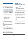
1
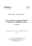
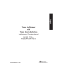
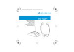
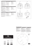
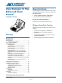
About this Guide
View Manager 16 Plus
Enhanced TOUCH
®
TRACKER
These installation instructions explain how to setup
the VM16+ Enhanced TOUCH TRACKER. Other related documents are:
• System Operator's Manual, 8000-2653-01
• Quick Reference Guide, 8000-2654-01
Installation Guide
If you need assistance...
A
B
P ee
l
Contact your Sensormatic Representative.
Info
Men
u
Ir is
Clo
se
C
1
O ut O n
p ut
O ff
Cle
2
5
Fl ip
6
7
O pe
D
3
4
ar
8
n
Pr ev
V ie
w
Pat
tern
9
Changes from Prior Version
Rep
P at ea t
tern
Seq
0
io us
Next
Significant changes are noted with revision bars in
margins.
• Updated bill of materials for RVEIMKITE.
• Moved location of installation diagrams in
document.
• Updated wiring diagrams for Intellex units and
Duplex Remote Panel.
• Updated Regulatory Compliance statement.
RCTT16BE
Contents
About this Guide................................................................... 1
Changes from Prior Version ......................................... 1
TOUCH TRACKER Installation................................................. 2
Installation Diagrams............................................................ 3
Installation Notes .......................................................... 3
Enhanced TOUCH TRACKER with Multiplexer
(DB25 connection)........................................................ 4
Enhanced TOUCH TRACKER with Multiplexer
(RJ11 connection) ........................................................ 5
Enhanced TOUCH TRACKER with Quad Splitter
(RJ45 connection) ........................................................ 6
Enhanced TOUCH TRACKER with RVQX7X Quad
Splitter........................................................................... 7
Enhanced TOUCH TRACKER with Intellex 1.x ................ 8
Enhanced Touch Tracker with Intellex 2.0 ................... 9
Enhanced Touch Tracker with Intellex 2.1 ................. 10
Enhanced TOUCH TRACKER and Duplex Remote Panel
(RVDRP)..................................................................... 11
Enhanced TOUCH TRACKER with Domes Only
(No External Unit) ....................................................... 12
Configuring the External Device......................................... 13
Setting Primary and Secondary Unit .................................. 13
Additional Touch Tracker Tasks......................................... 14
Displaying System Information ................................... 14
Performing the SensorNet Ping Test.......................... 14
Resetting a Dome ....................................................... 14
Adjusting V-Phase ...................................................... 14
Specifications ..................................................................... 15
SensorNet................................................................... 15
Enhanced Touch Tracker ........................................... 15
Declarations ....................................................................... 15
Regulatory Compliance .............................................. 15
© 2005 Sensormatic Electronics Corp.
RCTT16BE VM16 PLUS ENHANCED TOUCH TRACKER
INSTALLATION GUIDE
8000-2672-01, REV. D1
1 of 15
Note: Prior to installing the Enhanced TOUCH
TRACKERS, identify the type of external unit that will
connect to the Enhanced TOUCH TRACKER, if
applicable. Build any cables that are required.
Refer to the Installation Diagrams starting on
page 3 for specific instructions.
TOUCH TRACKER Installation
RVEIMKITE TOUCH TRACKER Installation Kit
Part Number
6003-0047-01
5899-0004-102
2880-0083-01
2816-7634-44
2109-0254-04
2141-0002
6002-0024-01
0649-0006-02
0649-0006-04
2450-0008-01
3600-0032-01
0300-1000-01
6003-0107-01
2125-0007-02
2130-0021-01
2103-0092-01
0650-1079-01
8000-2672-01
0649-0006-06
8000-2653-01
8000-2654-01
8000-1370-02
6003-0108-01
RPNR00
Description
CBL/A, MDR, 14',8 C,CROSS-P'D
SCR, TCUT, M2.9X9.5, PHP, ST,Z,T1
ANCH, PL, W/O SCR, 3/4L,#4-#6-#8
SCR, TYP AB, PHP, ST, Z, 8X1
CON, P, EUR,.2C,28-12G,1X5P
LUG, SPADE, INSUL, 22-168
CBL, 3C, 18G, CM
BAG PLASTIC 4 X 6 1/2 4MIL
BAG PLASTIC 8 X 10 4 MIL THK
LBL, BLNK, PAP, THERM, 89X76M, RL
PRINTING SPEC, LABEL
INTERCONNECT BOX, TOUCH TRACK
CBL/A, QUAD, SW, INTFCE
HOOD, D, 9P, EMI/RFI, 1/4 D CBL
CON, D,P, HSG, 9P, SSI
CONT, P, D, 26-22,AU
CABLE ASSY, VM8 TOUCHTRACKER/VI
INSTL INSTRS, TT ENHANCED
BAG, PLASTIC 12-1/2 X 14X4MIL
SYS OPERATOR'S MANUAL, VM16
SYS QUICK GUIDE, VM16
TTRACKER STRAIN RELIEF INSTR
CBL/A, VM16+/TNG, MUX/INTFCE
CBL/A, RS-232, 10', DB9F-DB9M
Quantity
1
1
2
2
1
3
16.5
1
1
1
0
1
1
1
1
3
1
1
1
1
1
1
1
1
1. Terminate the External Interconnect Module
(EIM) at the end of the SensorNet network. If
more than one Enhanced TOUCH TRACKER
controller will be installed, one TOUCH
TRACKER's EIM will be terminated; the other EIM
will be unterminated. Refer to the appropriate
wiring diagram for your configuration.
2. Mount each EIM on a wall or other surface
within 3m (10 feet) of the Touch Tracker
controller.
3. Connect the power transformer and SensorNet
cable to J3 on each EIM. If two Touch Trackers
will be installed, connect the SensorNet cable
from the first EIM to the second EIM.
4. Depending on the external unit that will be
attached to your system, connect the
appropriate cable to the DB9 connector on the
EIM. Refer to the appropriate wiring diagram for
additional details.
For Quad Splitter (RVQX7X) with DB9 Connector
These additional parts are required.
PN
Description
2125-0007-02 DB9 Hood
2103-0092-02 DB9 Female contact pins
2103-0092-01 DB9 Male contact pins
2130-0021-01 DB9 Male Connector
2130-0022-01 DB9 Female Connector
!
!
Quantity
2
5
5
1
1
5. Connect the data cable from J1 on the Primary
TOUCH TRACKER's EIM to the remote port on the
external unit. Refer to the appropriate wiring
diagram for additional details.
WARNING: RISK OF ELECTRIC
SHOCK! Disconnect AC Power to
the switch.
6. Connect the modular cable from J2 on each
EIM to the TOUCH TRACKER controller.
7. Connect the SensorNet cable from the dome to
the first EIM. Refer to the appropriate wiring
diagram for additional details.
CAUTION-Electrostatic Sensitive
Device: Follow proper handling
procedures to prevent component
failure.
8. Plug in the power transformer into a grounded,
3-wire receptacle.
Note: If the keypad and backlighting do not
illuminate when power is applied, unplug each
power transformer and repeat steps 3 through 8.
Depending on system configuration, it may take up
to 2 minutes for the Enhanced TOUCH TRACKER to
come completely online.
Continue with Configuring the External Device.
RCTT16BE VM16 PLUS ENHANCED TOUCH TRACKER
INSTALLATION GUIDE
8000-2672-01, REV. D1
2 of 15
Installation Notes
Installation Diagrams
• Depending on configuration, two Enhanced
TOUCH TRACKERS may be installed. Terminate
E1 on the EIM that is on the end point of the
SensorNet Network.
• The maximum combined SensorNet cable
length is 1000 m (one km or 3000').
• J-Box and dome wiring information is included
for information purposes only. Refer to the
J-Box or dome installation instructions for
complete wiring information.
The following pages illustrate the installation of the
VM16+ Enhanced Touch Tracker in the following
configurations:
Enhanced Touch Tracker with Multiplexer
(DB25 connection)................................................4
Enhanced Touch Tracker with Multiplexer
(RJ11 connection) ................................................5
Enhanced Touch Tracker with Quad Splitter
(RJ45 connection) ................................................6
Enhanced Touch Tracker with RVQX7X Quad
Splitter ...................................................................7
Enhanced TOUCH TRACKER with Intellex 1.x ...... 8
Enhanced Touch Tracker with Intellex 2.0.........9
Enhanced Touch Tracker with Intellex 2.1.......10
Enhanced Touch Tracker and Duplex Remote
Panel (RVDRP) ...................................................11
Enhanced TOUCH TRACKER with Domes Only (No
External Unit) ......................................................12
Refer to the appropriate diagram when connecting
the Enhanced Touch Tracker.
RCTT16BE VM16 PLUS ENHANCED TOUCH TRACKER
INSTALLATION GUIDE
8000-2672-01, REV. D1
3 of 15
Enhanced TOUCH TRACKER with Multiplexer (DB25 connection)
COLOR PIN
Orange
1
Yellow
2
Orange
Yellow
4
FUNCTION
Host A
Host B
Auxiliary A
Auxiliary B
COLOR
Orange
White
Red
Black
Yellow
PIN
1
2
3
4
5
FUNCTION
SensorNet A
28 Vac
Ground
28 Vac
SensorNet B
Your system supports up to
2 controllers. Terminate E1
on the EIM that is on the
end point of the SensorNet
Network.
The maximum combined
SensorNet cable length is
1000 m (3000').
Connect to
Remote
DB25F
COLOR
RED
BLACK
DB9M
2 Tx
5 Ground
DB25M
25 Rx
14 Ground
RCTT16BE VM16 PLUS ENHANCED TOUCH TRACKER
INSTALLATION GUIDE
8000-2672-01, REV. D1
4 of 15
Enhanced TOUCH TRACKER with Multiplexer (RJ11 connection)
COLOR PIN
Orange
1
Yellow
2
Orange
Yellow
4
FUNCTION
Host A
Host B
Auxiliary A
Auxiliary B
COLOR
Orange
White
Red
Black
Yellow
PIN
1
2
3
4
5
FUNCTION
SensorNet A
28 Vac
Ground
28 Vac
SensorNet B
To Dome
Refer to instructions
included with device.
Your system supports up to
2 controllers. Terminate E1
on the EIM that is on the
end point of the SensorNet
Network.
COLOR
RED
BLACK
PIN
2
5
FUNCTION
TRANSMIT
GROUND
The maximum combined
SensorNet cable length is
1000 m (3000').
RCTT16BE VM16 PLUS ENHANCED TOUCH TRACKER
INSTALLATION GUIDE
8000-2672-01, REV. D1
5 of 15
Enhanced TOUCH TRACKER with Quad Splitter (RJ45 connection)
COLOR PIN
Orange
1
Yellow
2
Orange
Yellow
4
FUNCTION
Host A
Host B
Auxiliary A
Auxiliary B
COLOR
Orange
White
Red
Black
Yellow
PIN
1
2
3
4
5
To Dome
FUNCTION
SensorNet A
28 Vac
Ground
28 Vac
SensorNet B
Refer to instructions
included with device.
The maximum combined
SensorNet cable length is
1000 m (3000').
TERMINATED
Only one Touch Tracker
may be installed with the
dual page Quad Splitter.
This EIM must be
terminated.
COLOR
RED
ORANGE
PIN
COLOR
GREEN
ORANGE
PIN
2
5
5
FUNCTION
TRANSMIT
GROUND
FUNCTION
TRANSMIT
GROUND
COLOR
GREEN
RED
ORANGE
RCTT16BE VM16 PLUS ENHANCED TOUCH TRACKER
INSTALLATION GUIDE
PIN
5
2
8000-2672-01, REV. D1
6 of 15
Enhanced TOUCH TRACKER with RVQX7X Quad Splitter
COLOR PIN
Orange
1
Yellow
2
Orange
Yellow
4
FUNCTION
Host A
Host B
Auxiliary A
Auxiliary B
COLOR
Orange
White
Red
Black
Yellow
PIN
1
2
3
4
5
FUNCTION
SensorNet A
28 Vac
Ground
28 Vac
SensorNet B
To Dome
Refer to instructions
included with device.
The maximum combined
SensorNet cable length is
1000 m (3000').
TERMINATED
Only one Touch Tracker may
be installed with the Quad
Splitter. This EIM must be
terminated.
PART
DB9 Hood
DB9 Female contact pins
DB9 Male contact pins
DB9 Male Connector
DB9 Female Connector
QTY
2
5
5
1
1
PN
2125-0007-02
2103-0092-02
2103-0092-01
2130-0021-01
2130-0022-01
EIM DB9M
2 Tx
2 Rx
5 Ground 1 Ground
RCTT16BE VM16 PLUS ENHANCED TOUCH TRACKER
INSTALLATION GUIDE
8000-2672-01, REV. D1
7 of 15
Enhanced TOUCH TRACKER with Intellex 1.x
J-Box P8
Color
Orange
Yellow
Orange
Yellow
Pin
1
2
3
4
J-B ox #1
J-Box P1-P6
Function
Host A
Host B
Auxiliary A
Auxiliary B
Color
Orange
White
Red
Black
Yellow
Pin
1
2
3
4
5
To Dome
Function
SensorNet A
28 Vac
Ground
28 Vac
SensorNet B
Refer to instructions
included with device.
P4
P1
P5
P6
P2
P8
P3
24 Vac A
Ground
24 Vac B
5
4
3 2 1
EIM #1
ASSY
0301-0340-01 REV-
3 2 1
TERMINATED
Only one Touch Tracker
E1
may be installed with
Intellex. This EIM must
be terminated.
DB9M
Straight-Thru Cable Wiring
EIM DB9F
2 Tx
3 Rx
5 Ground
RJ45
RJ45
COM 1
2 Rx
3 Tx
5 Ground
Intellex 1.x
(with DB9 Connector)
Primary
Touch Tracker
The maximum combined
SensorNet cable length
is 1000m (3000’).
Straight-Thru Cable
PN: RPNR00
DB9F
DB9 Connector
RCTT16BE VM16 PLUS ENHANCED TOUCH TRACKER
INSTALLATION GUIDE
8000-2672-01, REV. D1
8 of 15
Enhanced Touch Tracker with Intellex 2.0
J-B o x #1
J-Box P8
Color
Orange
Yellow
Orange
Yellow
Pin
1
2
3
4
To Dome
J-Box P1-P6
Function
Host A
Host B
Auxiliary A
Auxiliary B
Color
Orange
White
Red
Black
Yellow
Pin
1
2
3
4
5
Refer to instructions
included with device.
Function
SensorNet A
28 Vac
Ground
28 Vac
SensorNet B
P1
P4
P5
P2
P6
P3
P8
24 Vac A
Ground
24 Vac B
5
4
3 2 1
EIM #1
ASSY
0301-0340-01 REV-
3 2 1
Terminated
Only one Touch Tracker
may be installed with
Intellex. This EIM must
be terminated.
E1
DB9M
RJ45
RJ45
Straight-Thru Cable Wiring
EIM DB9F
2 Tx
3 Rx
5 Ground
COM 2
2 Rx
3 Tx
5 Ground
Intellex 2.0
Primary
Touch Tracker
The maximum combined
SensorNet cable length
is 1000m (3000’).
Straight-Thru Cable
PN: RPNR00
(with DB9 Connector)
DB9F
COM 1
COM 2
DB9 Connector
RCTT16BE VM16 PLUS ENHANCED TOUCH TRACKER
INSTALLATION GUIDE
8000-2672-01, REV. D1
9 of 15
Enhanced Touch Tracker with Intellex 2.1
J-Box P8
Color
Orange
Yellow
Orange
Yellow
Pin
1
2
3
4
J-Box P1-P6
Function
Host A
Host B
Auxiliary A
Auxiliary B
Color
Orange
White
Red
Black
Yellow
Pin
1
2
3
4
5
J-Box #1
Function
SensorNet A
28 Vac
Ground
28 Vac
SensorNet B
To Dome
Refer to instructions
included with device.
P4
P1
P5
P2
P6
Your system supports up to
2 controllers. Terminate E1
on the EIM that is on the
end point of the SensorNet
Network.
P8
P3
The maximum combined
SensorNet cable length
is 1000m (3000ft).
DB9M
RJ45
Secondary
Touch Tracker
RJ45
Primary
Touch Tracker
Straight-Thru Cable Wiring
EIM DB9F
2 Tx
3 Rx
5 Ground
COM 2
2 Rx
3 Tx
5 Ground
Intellex 2.1
Straight-Thru Cable
PN: RPNR00
(with DB9 Connector)
DB9F
COM 1 DB9 Connector
RCTT16BE VM16 PLUS ENHANCED TOUCH TRACKER
INSTALLATION GUIDE
Call monitor feature board
is used if Secondary Touch
Tracker is installed.
8000-2672-01, REV. D1
10 of 15
Enhanced TOUCH TRACKER and Duplex Remote Panel (RVDRP)
To Dome
Refer to instructions
included with device.
To Your Remote
Mux Location
12345
12345
12345
P4
P1
P5
P2
P6
P3
DOME 456
Jw2
T
12345
12345
DOME 123
Jw1
T
321
321
HOST
Jw3
12345
T
AUX
JW4
T
321
321
HOST
AUX
P8
RV2216 BACK VIEW
Pin 19
Pin 4
Pin 1
vcr
in
Pin 1
s-vhs s-vhs
4 conductor
straight- through RJ-11 cable
in
out
out
out
cam 16
main cam 1
REMOTE DUPLEX MUX (RVDRP)
J3
T=Terminated
U=Unterminated
EIM #1
DB9
J3
0300-1000-01
EIM #2
RJ45
RJ45
DB9
J2
J2
J1
Red
6003-0108-01
Pin 4
0300-1000-01
5
SECONDARY
TOUCH TRACKER
EIM DB9F Wiring
Color
Pin
Red
2
Black
5
Note: Green wire is not used.
NOTE: The Touch Tracker
is always connected to the
last output of the remote
multiplexers.
2
6003-0047-01
Back View
NOTE: Both ends of this
cable connect to the
ports labeled “data in”.
Black
6003-0106-01
IN OUT
Pin 1
J1
vcr
out
in
in
call
6003-0047-01
RCTT16BE VM16 PLUS ENHANCED TOUCH TRACKER
INSTALLATION GUIDE
PRIMARY
TOUCH TRACKER
8000-2672-01, REV. D1
11 of 15
Enhanced TOUCH TRACKER with Domes Only (No External Unit)
Use this wiring diagram when domes will be connected to dedicated monitors.
COLOR
Orange
Yellow
Black
Red
White
PIN
1
2
3
4
5
FUNCTION
SensorNet A
SensorNet B
24 Vac A
Ground
24 Vac B
COLOR
Orange
Yellow
Black
Red
White
PIN
FUNCTION
P1 Lead 5 SensorNet A
P1 Lead 6 SensorNet B
P7 Lead 1 24 Vac A
P7 Lead 2
Ground
P7 Lead 3 24 Vac B
The maximum combined
SensorNet cable length is
1000 m (3000').
Only one Touch Tracker may
be installed with standalone
configurations. This EIM must
be terminated.
RCTT16BE VM16 PLUS ENHANCED TOUCH TRACKER
INSTALLATION GUIDE
8000-2672-01, REV. D1
12 of 15
Configuring the External
Device
Setting Primary and
Secondary Unit
Use this procedure to select the external device
that connects to the Enhanced TOUCH TRACKER.
NOTE: Quad Splitter, Intellex 1.x and 2.0, and
stand-alone installations support only one Touch
Tracker.
1. From the primary Enhanced TOUCH TRACKER,
press Menu to configure the software for the
external system. The menu appears on the
LCD.
2. Use the Tracker Ball to scroll through the menu
until Config Devices appears on the LCD
screen. Press zoom or focus to select Config
Devices.
3. Press Next to scroll through the available
devices. Refer to the following chart to
determine which device to select.
Device Setting
Use with...
Device
=Mux 16
16-camera Multiplexer and
Intellex
= POSEM
Device
=Mux 9
9-camera Multiplexer
= POSEM
Device
=Quad
1. Press Menu.
2. Using the Tracker Ball, scroll the menu choices
until Tog Primary/2nd appears on the LCD.
3. Press zoom or focus to select Tog
Primary/2nd. Zoom selects the top line; focus
selects the bottom line.
4. Press Next to toggle between setting the
Enhanced TOUCH TRACKER as primary or
secondary. When the appropriate choice
appears on the LCD, press Menu. The
Enhanced TOUCH TRACKER will reset.
Repeat this procedure for each Enhanced TOUCH
TRACKER.
= POSEM
Device
=Mux 4
If you have two Enhanced TOUCH TRACKERS
installed, one must be designated as Primary; the
other must be designated as Secondary. If you
have only one Enhanced TOUCH TRACKER installed,
it must be designated as Primary.
4-camera Multiplexer, dual page
Quad Splitter, and Quad Splitter
(RVQX7X)
Quad Splitter with DB9F-RJ45
connection
= POSEM
Device
=None
Domes connected to dedicated
monitors (no external device).
Device
=PC
For Service use only
4. When the correct configuration appears on the
LCD, press Menu.
Continue with Setting Primary and Secondary
Unit.
RCTT16BE VM16 PLUS ENHANCED TOUCH TRACKER
INSTALLATION GUIDE
8000-2672-01, REV. D1
13 of 15
Additional Touch Tracker
Tasks
The following maintenance functions can be
performed using the Touch Tracker. When using
the menus, pressing Zoom selects the first line of
the LCD; pressing Focus selects the second line of
the LCD.
Displaying System Information
This procedure displays system information about the
Enhanced TOUCH TRACKER being used.
1. Use the number buttons to the select the dome to
2.
3.
4.
5.
reset, and then press
(Camera button).
Press Menu.
Using the Tracker Ball, scroll through the choices
until System Info appears on the LCD.
Press Zoom or Focus to select System Info.
Press Next or Previous to scroll through the
information.
The LCD displays the following information:
This feature allows you to reinitialize a SpeedDome
or SpeedDome Ultra family camera dome.
1. Use the number buttons to the select the dome
to reset then press
(Camera button).
2. Press Menu.
3. Using the Tracker Ball, scroll through the
choices until Reset Dome appears on the
LCD.
4. Press Zoom or Focus to select Reset Dome.
The Enhanced TOUCH TRACKER sends a request to
the selected dome to reboot. After a brief delay, the
TOUCH TRACKER resumes camera control mode.
Adjusting V-Phase
Use this procedure to adjust the vertical phase for
cameras installed with your system.
1. Press Menu.
− ROM Checksum Values
2. Using the Tracker Ball, scroll through the
choices until Adjust V-phase appears on
the LCD.
− Calibration information (display should read all
0)
3. Press Zoom or Focus to select Adjust Vphase.
− Product Code Flash Version
4. Press Next or Previous to observe V-phase
through the oscilloscope or Fluke scope.
− Unit Type: Primary or Secondary
− Product Code EEPROM Version
6. Press Menu to resume camera control mode.
Performing the SensorNet Ping
Test
This procedure tests communications between the
Enhanced TOUCH TRACKER and domes installed at
your facility.
1. Use the number buttons to the select the dome to
2.
3.
Resetting a Dome
5. When you are satisfied with the setting, press
Menu to exit.
Note: Off-line domes or fixed cameras will
generate a warning beep and not permit the use of
the V-phase utility.
(Camera button).
ping then press
Press Menu.
Using the Tracker Ball, scroll through the choices
until Ping Dome/TTR appears on the LCD.
Press Zoom or Focus to select Ping
Dome/TTR.
5. Press Next to start the network test on the
primary or secondary Touch Tracker.
6. Press Menu to exit.
Note: Off-line domes or fixed cameras will generate a
warning beep and not permit the use of the Ping test.
4.
RCTT16BE VM16 PLUS ENHANCED TOUCH TRACKER
INSTALLATION GUIDE
8000-2672-01, REV. D1
14 of 15
Specifications
Declarations
SensorNet
Regulatory Compliance
Bit Rate:............................. 230.4Kbps
Emissions:.......................... FCC Part 15 Class A;
EN 55022 Class B.
Physical Layer: ................. Non-shielded twisted
pair
Immunity: ........................... EN 50130-4
Safety
Link Layer Protocol: .......... SDLC
Application Protocol: ......... Proprietary
CSA - C22.2 No 950-M89;
Network Nodes: ................ Touch Tracker,
SensorNet Domes
EN 60950.
FCC COMPLIANCE: This equipment has been tested and found to
comply with Part 15 of the FCC Rules. Operation is subject to the
following two conditions: 1) this device may not cause harmful
interference, and 2) this device must accept any interference received,
including interference that may cause undesired operation.
Enhanced Touch Tracker
Operator Inputs: ............... 31-key keypad,
4 micro-switches,
1 Tracker Ball
EQUIPMENT MODIFICATION CAUTION: Equipment changes
or modifications not expressly approved by Sensormatic Electronics
Corporation, the party responsible for FCC compliance, could void the
user's authority to operate the equipment and could create a hazardous
condition.
Operator Outputs: ............. LCD screen
(2-line x 16 character)
Control Input/Output: ........ SensorNet (Domes,
Touch Tracker), RS-232
(multiplexer or quad
splitter)
Electrical
Power Source: .................. 16–30Vac at 50/60Hz
Power Consumption: ........ 1400mA, 2A max.
Mechanical, Touch Tracker
Height: .............................. 13cm (5in.)
Width: ............................... 19cm (7.5in.)
Depth: ............................... 26cm (10in.)
Weight: ............................. 1kg (2.2lbs)
Environmental
Operating Temperature: ... 0°–50°C
(32°–122°F)
Relative Humidity: ............ 0%–95%
non-condensing
Storage Temperature: ...... -20°–64°C
(-4°–149°F)
Product Compatibility
SensorNet Interface: ........ SpeedDome family
RS-232 Serial Port: .......... Monochrome Mux,
Color Mux,
Monochrome Quad,
Color Quad, Intellex,
Standard PC
Complies with:
UL1950;
Other Declarations
INSTALLATION: This installation should be made by a qualified
service person and should conform to all local codes. In North
America, this device is intended to be supplied from a nominal 24Vac
Class 2 power supply. In the EU, this device is intended to be powered
from a Certified (for the country of use), CE marked, source of SELV,
not exceeding 240 VA available.
INSTALLATION: Diese Installation sollte von einem qualifizierten
Wartungstechniker vorgenommen werden und allen örtlichen
Vorschriften entsprechen. In Nordamerika ist dieses Gerät für die
Stromversorgung durch ein Netzgerät der Klasse 2 mit einer
Nennleistung von 24 V Wechselstrom vorgesehen. In der EG ist dieses
Gerät für die Stromversorgung durch eine (für das Verwendungsland)
zertifizierte, mit der CE Marke versehene Schutzkleinspannungsquelle
(SELV) vorgesehen, die 240 V Wechselstrom nicht überschreiten darf.
WARRANTY DISCLAIMER: Sensormatic Electronics Corporation
makes no representation or warranty with respect to the contents
hereof and specifically disclaims any implied warranties of
merchantability or fitness for any particular purpose. Further,
Sensormatic Electronics Corporation reserves the right to revise this
publication and make changes from time to time in the content hereof
without obligation of Sensormatic Electronics Corporation to notify
any person of such revision or changes.
LIMITED RIGHTS NOTICE: For units of the Department of
Defense, all documentation and manuals were developed at private
expense and no part of it was developed using Government Funds.
The restrictions governing the use and disclosure of technical data
marked with this legend are set forth in the definition of “limited
rights” in paragraph (a) (15) of the clause of DFARS 252.227.7013.
Unpublished - rights reserved under the Copyright Laws of the United
States.
TRADEMARK NOTICE: TOUCH TRACKER, Sensormatic, and the
Sensormatic logo are trademarks or registered trademarks of
Sensormatic Electronics Corporation. Other product names mentioned
herein may be trademarks or registered trademarks of Sensormatic or
other companies.
No part of this guide may be reproduced in any form without written
permission from Sensormatic Electronics Corporation.
RLJ 5/05
RCTT16BE VM16 PLUS ENHANCED TOUCH TRACKER
INSTALLATION GUIDE
8000-2672-01, REV. D1
15 of 15