1
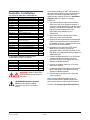
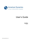
ADTT16E Advanced
Dome Controller
About this Guide
These installation instructions explain how to setup
the ADTT16E advanced dome controller. Other
related documents are:
Installation Guide
• Operator's Manual, 8200-0306-02
• Quick Reference Guide, 8200-0306-03
• Programming Worksheets, 8200-0306-04
A
B
Pe
el
Info
Me
Cle
Ir is
Clo
se
C
1
Ou On
tp u
t
O ff
nu
2
D
3
4
ar
5
6
7
V ie
8
Op
en
About the ADTT16E
Advanced Dome Controller
Fli
p
Pa
9
w
ttern
Re
pe
P a at
tter
n
0
S eq
Pr ev
io us
Nex
t
The ADTT16E advanced dome controller is a
programmable video controller (Touch Tracker®)
that allows you to monitor sixteen video inputs,
including SensorNet programmable domes, the
Viewer™ video imaging system, and fixed
cameras. The controller’s tracker ball provides
pan/tilt control of the currently selected dome.
Buttons for lens zoom, focus and iris functions are
located near the tracker ball.
01ADTT16E
Contents
Standard features include programming/control of
up to 96 presets and three patterns per dome. The
ADTT16E advanced dome controller can be used
as a standalone unit for controlling a single video
input or several inputs on dedicated monitors. In
addition, with Multivision Quest Triplex
multiplexers, the operator can remotely freeze an
image, digital zoom, as well as run multiplexer
sequences and select the cameras to display in
each window of a multi-image display.
About this Guide.................................................... 1
About the ADTT16E Advanced Dome Controller.. 1
Controller Installation............................................. 2
Installation Diagrams............................................. 3
Configuring the External Device.......................... 12
Setting Primary and Secondary Unit ................... 12
Additional Tasks .................................................. 13
Specifications ...................................................... 14
Declarations ........................................................ 14
© 2004 Sensormatic Electronics Corp.
ADTT16E ADVANCED DOME CONTROLLER
INSTALLATION GUIDE
8200-0306-01, REV. C
1 of 14
Note: Before installing the ADTT16E advanced
dome controllers, identify the type of external unit
that will be connected, if applicable. Build any
cables that are required. Refer to the Installation
Diagrams starting on page 3 for specific
instructions.
Controller Installation
0351-1694-03 KIT,TTENH,ADTT16,W/RJ45&INT BX
Part Number
Description
Qty
6003-0047-01
CBL/A,MDR,14',8C,CROSS-PINNED
1
5899-0004-102
SCR,TCUT,M2.9X9.5,PHP,ST,Z,T1
1
2880-0083-01
ANCH,PL,W/O SCR,3/4L,#4-#6-#8
2
2816-7634-44
2109-0254-04
SCR,TYP AB,PHP,ST,Z,"8X1"
CON,P,EUR,.2C,28-12G,1X5P
2
1
2141-0002
LUG,SPADE,INSUL,22-16G,#8 STUD
3
6002-0024-01
CBL,3C,18G,CM
16.5 ft
0300-1000-01
INTERCONNECT BOX,TOUCH
TRACK
1
6003-0107-01
CBL/A,QUAD,SW,INTFCE
1
2125-0007-02
2130-0021-01
HOOD,D,9P,EMI/RFI,1/4 D CBL
CON,D,P,HSG,9P,NICKEL PLATE
1
1
2103-0092-01
CONT,P,D,26-22,AU
3
0650-1079-01
CABLE ASSY,VM8
TOUCHTRACKER/VI
1
8200-0306-02
OPS MANUAL,ADTT16E TTR
1
8200-0306-03
QUICK REF GUIDE,ADTT16E TTR
1
8000-1370-02
TTRACKER STRAIN RELIEF INSTR
1
6003-0108-01
8200-0306-01
CBL/A,VM16+/TNG,MUX/INTFCE
INSTALL GUIDE,ADTT16E TTR
1
1
RPNR00
CBL/A,RS232,10',DB9F-DB9M
1
0652-0151-01
CABLE ASSY, MUX/TOUCHTRACKER
1
8200-0306-04
PROG WORKSHEETS,ADTT16E TTR
1
1. Terminate the External Interconnect Module
(EIM) at the end of the SensorNet network. If
more than one advanced dome controller will be
installed, one EIM will be terminated; the other
EIM will be unterminated. Refer to the
appropriate wiring diagram for your
configuration.
2. Mount each EIM on a wall or other surface
within 3m (10 feet) of the controller.
3. Connect the power transformer and SensorNet
cable to J3 on each EIM. If two controllers will
be installed, connect the SensorNet cable from
the first EIM to the second EIM.
4. Depending on the external unit that will be
attached to your system, connect the
appropriate cable to the DB9 connector on the
EIM. Refer to the appropriate wiring diagram for
additional details.
5. Connect the data cable from J1 on the Primary
controller’s EIM to the remote port on the
external unit. Refer to the appropriate wiring
diagram for additional details.
For Quad Splitter (RVQX7X) with DB9 Connector
These additional parts are required.
PN
Description
Qty
2125-0007-02
DB9 Hood
2
2103-0092-02
DB9 Female contact pins
5
2103-0092-01
DB9 Male contact pins
5
2130-0021-01
DB9 Male Connector
1
2130-0022-01
DB9 Female Connector
1
7. Connect the SensorNet cable from the dome to
the first EIM. Refer to the appropriate wiring
diagram for additional details.
WARNING: RISK OF ELECTRIC
SHOCK! Disconnect AC Power to
the switch.
!
!
6. Connect the modular cable from J2 on each
EIM to the controller.
8. Plug the power transformer into a grounded,
3-wire receptacle.
Note: If the keypad and backlighting do not
illuminate when power is applied, unplug each
power transformer and repeat steps 3 through 8.
CAUTION-Electrostatic Sensitive
Device: Follow proper handling
procedures to prevent component
failure.
Continue with Configuring the External Device.
ADTT16E ADVANCED DOME CONTROLLER
INSTALLATION GUIDE
8200-0306-01, REV. C
2 of 14
Installation Notes
Installation Diagrams
• Depending on configuration, two advanced
dome controllers may be installed. Terminate
E1 on the EIM that is on the end of the
SensorNet network.
• The maximum combined SensorNet cable
length is 1000 m (one km or 3000').
• J-Box and dome wiring information is included
for information purposes only. Refer to the
appropriate installation instructions for complete
wiring information.
• The ADTT16E controller requires a separate,
isolated transformer. Do not install in parallel
with a dome. Refer to Figure 1 for universal
transformer wiring information.
The following pages illustrate how to install the
ADTT16E advanced dome controller with different
devices:
Installing with Quest Multiplexer............................ 4
Installing with DB25 Connection Multiplexer ......... 5
Installing with RJ11 Connection Multiplexer.......... 6
Installing with RJ45 Connection Quad Splitter ...... 7
Installing with RVQX7X Quad Splitter ................... 8
Installing with Intellex 2.x DVMS and Newer......... 9
Installing with RVDRP Duplex Remote Panel .... 10
Installing with Domes Only (No External Unit) .... 11
Figure 1: Universal Transformer wiring
information
Refer to the appropriate diagram when connecting
the advanced dome controller.
COM
12V~
17V~
20V~
24V~
Universal Transformer
ADTT16E ADVANCED DOME CONTROLLER
INSTALLATION GUIDE
EIM J3
Function
Pin 3
Ground
COM
Pin 2
24Vac A
24V~
Pin 4
24Vac B
8200-0306-01, REV. C
3 of 14
Installing with Quest Multiplexer
IMPORTANT! ADTT16E requires firmware 0701-2833-0103 (EEPROM)/0701-2834-0201 (Flash PROM)
or newer to work with Quest multiplexers.
Color
Orange
Yellow
Orange
Yellow
J-Box #1
J-Box P1-P6
J-Box P8
Pin
1
2
3
4
Color
Orange
White
Red
Black
Yellow
Function
Host A
Host B
Auxiliary A
Auxiliary B
Pin
1
2
3
4
5
Function
SensorNet A
28 Vac
Ground
28 Vac
SensorNet B
SensorNet A
SensorNet B
To Dome
Refer to instructions
included with
device.
EIM Transformers
24 Vac A
Ground
24 Vac B
Note:
The maximum combined
SensorNet cable length is
1000 m (3000 ft).
24 Vac A
Ground
24 Vac B
EIM #1
EIM #2
Note:
Your system supports two
controllers. Terminate E1 on
the EIM that is on the end of
the SensorNet network.
Unterminated
RJ45
RJ45
DB9M
Terminated
RJ45
Multiplexer-Touch Tracker Cable
0652-0151-01
RJ45
Secondary
Touch Tracker
Primary
Touch Tracker
Touch Tracker - Multiplexer Cable Wiring
Pin 1
Clip down
RJ-11
EIM DB9 (M)
Quest Mux RJ-11
Pin
Function
Pin
Function
2
Transmit
5
Receive B (RB)
5
Ground
4
Receive A (RA)
Quest Triplex Multiplexer
RS-485
Multiplexer RJ-11 Connector Pin Assignment
6
1
6
1
Pin
1
2
3
4
5
6
Definition
+12V
GND
RA
RB
-
Direction
External Device Power Supply Output
External Device Ground Supply Output
Input/Output
Input/Output
-
ADTT16E ADVANCED DOME CONTROLLER
INSTALLATION GUIDE
8200-0306-01, REV. C
4 of 14
Installing with DB25 Connection Multiplexer
J-Box P1-P6
J-Box P8
Color
Orange
Yellow
Orange
Yellow
Pin
1
2
3
4
Color
Orange
White
Red
Black
Yellow
Function
Host A
Host B
Auxiliary A
Auxiliary B
J-Box #1
Pin
1
2
3
4
5
Function
SensorNet A
28 Vac
Ground
28 Vac
SensorNet B
To Dome
SensorNet A
SensorNet B
Refer to instructions
included with device.
EIM Transformers
24 Vac A
Ground
24 Vac B
Note:
The maximum
combined SensorNet
cable length is 1000
m (3000').
24 Vac A
Ground
24 Vac B
EIM #1
EIM #2
Unterminated
Note:
Your system supports two
controllers. Terminate E1 on
the EIM that is on the end of
the SensorNet network.
RJ45
DB9M
RJ45
RJ45
Secondary
Touch Tracker
Terminated
RJ45
Connect to
Remote DB25F
Color
Red
Black
DB9M
2 Tx
5 Ground
Primary
Touch Tracker
DB25M
25 Rx
14 Ground
DB25M
Multiplexer
(with DB25 Connector)
remote
in
call mon
power
out
12 VDC
alarm
main mon
vcr
cam 1
cam 2
cam 3
cam 4
ADTT16E ADVANCED DOME CONTROLLER
INSTALLATION GUIDE
cam 5
cam 6
cam 7
cam 8
cam 9
cam 10
cam 11
cam 12
cam 13
cam 14 cam 15
cam 16
8200-0306-01, REV. C
5 of 14
Installing with RJ11 Connection Multiplexer
J-Box P8
Color
Orange
Yellow
Orange
Yellow
J-Box #1
J-Box P1-P6
Pin
1
2
3
4
Function
Host A
Host B
Auxiliary A
Auxiliary B
Color
Orange
White
Red
Black
Yellow
Pin
1
2
3
4
5
Function
SensorNet A
28 Vac
Ground
28 Vac
SensorNet B
SensorNet A
SensorNet B
To Dome
Refer to instructions
included with device.
EIM Transformers
24 Vac A
Ground
24 Vac B
Note:
The maximum combined
SensorNet cable length is
1000 m (3000 ft).
24 Vac A
Ground
24 Vac B
EIM #1
EIM #2
Unterminated
DB9M
Pin
2
5
Secondary
Touch Tracker
Terminated
EIM DB9 Wiring
Color
Red
Black
RJ45
RJ45
Function
Transmit
Ground
Note: Pin 3 is not used; do not
connect it.
RJ45
Primary
Touch Tracker
Note:
Your system supports two
controllers. Terminate E1 on
the EIM that is on the end of
the SensorNet network.
Multiplexer Interface Cable
6003-0108-01
RJ11
RJ45
Multiplexer (with RJ11 Connector)
RJ11
Connects to
Remote In
ADTT16E ADVANCED DOME CONTROLLER
INSTALLATION GUIDE
8200-0306-01, REV. C
6 of 14
Installing with RJ45 Connection Quad Splitter
J-Box P8
Color
Orange
Yellow
Orange
Yellow
J-Box #1
J-Box P1-P6
Pin
1
2
3
4
Function
Host A
Host B
Auxiliary A
Auxiliary B
Color
Orange
White
Red
Black
Yellow
Pin
1
2
3
4
5
Function
SensorNet A
28 Vac
Ground
28 Vac
SensorNet B
To Dome
SensorNet A
SensorNet B
Refer to instructions
included with device.
EIM Transformer
24 Vac A
Note:
The maximum combined
SensorNet cable length is
1000 m (3000').
Ground
24 Vac B
EIM #1
Terminated
DB9M
Note:
Only one Touch Tracker may
be installed with the dual
page Quad Splitter. This EIM
must be terminated.
RJ45
Color Quad DB9M
Color
Red
Orange
Pin
2
5
Function
Transmit
Ground
RJ45
Primary
Touch Tracker
Monochrome Quad DB9M
Green
Orange
3
4
Transmit
Ground
RJ-45 Wiring
Color
Green
Red
Quad Splitter Interface Cable
6003-0107-01
Quad Processor
(with RJ-45 connector)
ADTT16E ADVANCED DOME CONTROLLER
INSTALLATION GUIDE
RJ45
Pin 1
Clip Up
8200-0306-01, REV. C
7 of 14
Pin
5
4
Installing with RVQX7X Quad Splitter
J-Box P8
Color
Orange
Yellow
Orange
Yellow
J-Box P1-P6
Pin
1
2
3
4
Function
Host A
Host B
Auxiliary A
Auxiliary B
Color
Orange
White
Red
Black
Yellow
Pin
1
2
3
4
5
J-Box #1
To Dome
Function
SensorNet A
28 Vac
Ground
28 Vac
SensorNet B
SensorNet A
SensorNet B
Refer to instructions
included with device.
Note:
The maximum combined
SensorNet cable length is
1000 m (3000').
EIM Transformer
24 Vac A
Ground
24 Vac B
EIM #1
Terminated
Note:
Only one Touch Tracker may
be installed with the dual
page Quad Splitter. This EIM
must be terminated.
RJ45
DB9M
Serial Cable Wiring
EIM DB9 (M)
2 TX
5 Ground
Quad DB9 (F)
2 RX
1 Ground
Primary
Touch Tracker
RJ45
Note:
The serial cable is not included in the kit. The
following additional parts are required:
Serial Cable
Description
DB9 Hood
DB9 Female contact pins
DB9 Male contact pins
DB9 Male connector
DB9 Female connector
DB9F
Qty
2
5
5
1
1
PN
2125-0007-02
2103-0092-02
2103-0092-01
2130-0021-01
2130-0022-01
RVQX7X Quad Processor
(with DB9 connector)
in
power
remote
out
12 vdc. 1amp
alarm
monitor
vcr
G1 G2 G3 G4
ADTT16E ADVANCED DOME CONTROLLER
INSTALLATION GUIDE
cam 1
cam 2
cam 3
cam 4
8200-0306-01, REV. C
8 of 14
Installing with Intellex 2.x DVMS and Newer
Color
Orange
Yellow
Orange
Yellow
J-Box #1
J-Box P1-P6
J-Box P8
Pin
1
2
3
4
Color
Orange
White
Red
Black
Yellow
Function
Host A
Host B
Auxiliary A
Auxiliary B
Pin
1
2
3
4
5
Function
SensorNet A
28 Vac
Ground
28 Vac
SensorNet B
SensorNet A
SensorNet B
P4
To Dome
Refer to instructions
included with device.
P1
P5
P2
P6
P8
P3
EIM Transformers
Note:
The maximum combined
SensorNet cable length is
1000 m (3000').
24 Vac A
Ground
24 Vac B
24 Vac A
Ground
24 Vac B
EIM #1
EIM #2
Unterminated
DB9M
RJ45
RJ45
Terminated
Secondary
Touch Tracker
RJ45
RJ45
Primary
Touch Tracker
Straight-Thru Cable Wiring
EIM DB9F
2 Tx
3 Rx
5 Ground
COM 2
2 Rx
3 Tx
5 Ground
Straight-Thru Cable
(RPNR00)
Note:
Your system supports two
controllers. Terminate E1 on
the EIM that is on the end of
the SensorNet Network.
Call monitor feature board
is used if Secondary Touch
Tracker is installed.
DB9F connect
to COM2
COM 2
DB9 Connector
Intellex 2.x or newer
(with DB9 connector)
ADTT16E ADVANCED DOME CONTROLLER
INSTALLATION GUIDE
Note:
Intellex back panel may look
different depending upon the
model. All newer Intellex systems
will connect to COM2.
For older models, contact support.
8200-0306-01, REV. C
9 of 14
Installing with RVDRP Duplex Remote Panel
J-Box #1
J-Box P1-P6
J-Box P8
Color
Orange
Yellow
Orange
Yellow
Pin
1
2
3
4
Color
Orange
White
Red
Black
Yellow
Function
Host A
Host B
Auxiliary A
Auxiliary B
Pin
1
2
3
4
5
SensorNet A
Function
SensorNet A
28 Vac
Ground
28 Vac
SensorNet B
To Dome
SensorNet B
Refer to instructions
included with device.
EIM Transformers
24 Vac A
Ground
24 Vac B
Note:
The maximum combined
SensorNet cable length is
1000 m (3000 ft).
24 Vac A
Ground
24 Vac B
EIM #2
EIM #1
Note:
Your system supports two
controllers. Terminate E1 on
the EIM that is on the end of
the SensorNet network.
Unterminated
RJ45
EIM DB9 Wiring
Color
Red
Black
Pin
2
5
RJ45
RJ45
DB9M
Terminated
Function
Transmit
Ground
RJ45
Secondary
Touch Tracker
Primary
Touch Tracker
Note: Green wire is not used.
Multiplexer Interface Cable
6003-0108-01
Note:
The Touch Tracker always
connects to the last output of
the remote multiplexers.
RJ11
IN OUT Remote Duplex Mux (RVDRP)
(Rear View)
4-conductor Straight-Thru RJ-11 Cable
6003-0106-01
Note:
Both ends of RJ-11 cable connect
to the ports labeled “Data In”
Multiplexer
ADTT16E ADVANCED DOME CONTROLLER
INSTALLATION GUIDE
8200-0306-01, REV. C
10 of 14
Installing with Domes Only (No External Unit)
Use this wiring diagram when domes will be connected to dedicated monitors.
SpeedDome UniCard P3 Wiring
COLOR
PIN
FUNCTION
Orange
1
SensorNet A
Yellow
2
SensorNet B
Black
3
24 Vac A
Red
4
Ground
White
5
24 Vac B
SpeedDome Ultra
I/O Board
SpeedDome
UniCard
Transformer
SensorNet A
SensorNet B
24 Vac A
Ground
24 Vac B
SpeedDome Ultra I/O Board Wiring
COLOR
PIN
Orange
P1 Lead 5
FUNCTION
SensorNet A
Yellow
P1 Lead 6
SensorNet B
Black
P7 Lead 1
24 Vac A
Red
P7 Lead 2
Ground
White
P7 Lead 3
24 Vac B
Transformer
24 Vac A
Ground
24 Vac B
Note:
The maximum combined
SensorNet cable length is
1000 m (3000 ft).
EIM Transformer
24 Vac A
Ground
24 Vac B
EIM
Terminated
RJ45
Note:
Only one Touch Tracker may be
installed in standalone
configurations. This EIM must be
terminated.
RJ45
ADTT16E ADVANCED DOME CONTROLLER
INSTALLATION GUIDE
Primary
Touch Tracker
8200-0306-01, REV. C
11 of 14
Configuring the External
Device
Setting Primary and
Secondary Unit
Use this procedure to select the external device
that connects to the advanced dome controller.
NOTE: Quad Splitter, Intellex 1.x and 2.0, and
stand-alone installations support only one
controller.
1. From the primary controller, press Menu to
configure the software for the external system.
The menu appears on the LCD.
If you have two advanced dome controllers
installed, one must be designated as Primary; the
other must be designated as Secondary. If you
have only one controller installed, it must be
designated as Primary.
2. Scroll through the menu items until
Config Devices appears on the LCD screen.
Press Zoom or Focus to select.
1. Press Menu.
3. Press Next to scroll through the available
devices. Refer to the following chart to
determine which device to select.
Device Setting
Device=Quad
=POSEM
Device=Mux 4
=POSEM
2. Scroll through the menu items until Tog
Primary/2nd appears on the LCD. Press
Zoom or Focus to select.
Use with...
3. Press Next to toggle between setting the
controller as primary or secondary. When the
appropriate choice appears on the LCD, press
Menu. The controller will reset.
Quad Splitter with DB9F-RJ45
connection
Standard 4-camera Multiplexer,
dual page Quad Splitter, and
Quad Splitter (RVQX7X)
Device=Mux 9
=POSEM
Device=Mux 16
=POSEM
Device=Mux 4
=Duplex
Device=Mux 9
=Duplex
Device=Mux 16
=Duplex
Device=Mux 10
=Triplex
Device=Mux 16
=Triplex
Standard 9-channel multiplexer
PC
Reserved for service use.
Remote
Use this option if the Touch
Tracker is installed at a remote
location and communicates at
1200 baud.
None
No external device is
connected.
Repeat this procedure for each advanced dome
controller.
Standard 16-channel multiplexer
and Intellex
4-channel Quest Duplex
multiplexer
9-channel Quest Duplex
multiplexer
16-channel Quest Duplex
multiplexer.
10-channel Quest Triplex
multiplexer
16-channel Quest Triplex
multiplexer.
4. When the correct configuration appears on the
LCD, press Menu.
Continue with Setting Primary and Secondary
Unit.
ADTT16E ADVANCED DOME CONTROLLER
INSTALLATION GUIDE
8200-0306-01, REV. C
12 of 14
Resetting a Dome
Additional Tasks
This feature allows you to reinitialize a SpeedDome
series camera dome.
The following maintenance functions can be
performed using the advanced dome controller.
When using the menus, pressing Zoom selects the
first line of the LCD; pressing Focus selects the
second line of the LCD.
1. Use the number buttons to the select the dome
to reset then press
(Camera button).
2. Press Menu.
Displaying System Information
3. Scroll through the menu items until
Reset Dome appears on the LCD. Press
Zoom or Focus to select.
This procedure allows you to display system
information about the advanced dome controller
you are using.
1. Press Menu.
2. Scroll through the menu items until
Show System Info appears on the LCD.
Press Zoom or Focus.
The following system information is available:
The advanced dome controller sends a request to
the selected dome to reboot. After a brief delay, the
controller resumes camera control mode.
Adjusting V-Phase
− Unit Type: Primary or Secondary
Use this procedure to adjust the vertical phase for
cameras installed with your system.
− ROM Checksum Values
1. Press Menu.
− Calibration information (display should read
all 0)
2. Scroll through the menu items until Adjust
V-phase appears on the LCD. Press Zoom or
Focus to select.
− Product Code Flash Version
− Product Code EEPROM Version
3. Press Next or Previous to scroll through the
information.
4. Press Menu when finished reviewing the
system information.
3. Press Next or Previous to observe V-phase
through the oscilloscope or Fluke scope.
4. When you are satisfied with the setting, press
Menu to exit.
Note: Off-line domes or fixed cameras will
generate a warning beep and not permit the use of
the V-phase utility.
Performing the SensorNet Ping
Test
This procedure tests communications between the
advanced dome controller and other SensorNet
devices (domes or other controller).
1. Press Menu.
2. Scroll through the menu items until Ping
Dome/TTR appears on the LCD. Press Zoom or
Focus to select.
3. The LCD displays the dome communication
(ping) test information.
4. Press Next to display the controller ping test
information.
5. Make note if any of the tests fail. Press Menu to
exit.
Note: Off-line domes or fixed cameras will
generate a warning beep and not permit the use of
the Ping test.
ADTT16E ADVANCED DOME CONTROLLER
INSTALLATION GUIDE
8200-0306-01, REV. C
13 of 14
Specifications
Declarations
SensorNet
Regulatory Compliance
Bit Rate.......................................................... 230.4Kbps
Emissions ........................FCC: 47 CFR Part 15, Class A
CE: EN55022 Class B
CE: EN61000-3-2
CE: EN61000-3-3
AS/NZS 3548, Class A
CISPR22
ICES-003
Physical Layer ......................... Non-shielded twisted pair
Link Layer Protocol ................................................. SDLC
Application Protocol ........................................ Proprietary
Network Nodes ................................................ Controller,
SensorNet domes
Immunity ............................................... CE: EN50130-4
Safety ........................................................... UL: UL1950
cUL: CSA 22.2 No. 950
IEC950
CE: EN60950
Advanced Dome Controller
Operator Inputs........................................ 31-key keypad,
4 micro-switches,
1 Tracker Ball
Operator Outputs ...........................................LCD screen
2-line x 16 characters
FCC COMPLIANCE: This equipment complies with Part 15 of the
FCC rules for Class A digital devices when installed and used in
accordance with the instruction manual. Following these rules
provides reasonable protection against harmful interference from
equipment operated in a commercial area. This equipment should not
be installed in a residential area as it can radiate radio frequency
energy that could interfere with radio communications, a situation the
user would have to fix at their own expense.
Control Input/Output ......... SensorNet (domes, controller)
RS232 (multiplexer or quad splitter)
Electrical
Power Source: .............................. 16–32Vac at 50/60Hz
EQUIPMENT MODIFICATION CAUTION: Equipment changes
or modifications not expressly approved by Sensormatic Electronics
Corporation, the party responsible for FCC compliance, could void the
user's authority to operate the equipment and could create a hazardous
condition. See About the ADTT16E Advanced Dome Controller on
page 1.
Power Consumption: .......................... 1400mA, 2A max.
Mechanical
Height .............................................................13cm (5in.)
Width ........................................................19.4cm (7.5in.)
Other Declarations
Depth ............................................................26cm (10in.)
Thank you for using American Dynamics products. We support our products
through an extensive and worldwide network of dealers. The dealer, through
whom you originally purchased this product, is your point of contact if you
have a need for service or support. Our dealers are fully empowered to provide
the very best in customer service and support. Dealers should contact American
Dynamics at (800) 507-6268 or (561) 912-6259 or on the web at
www.americandynamics.net.
Weight ........................................................... 1kg (2.2lbs)
Environmental
Operating Temperature: ................................. -10°–50°C
(14°–122°F)
WARRANTY DISCLAIMER: Sensormatic Electronics Corporation makes no
representation or warranty with respect to the contents hereof and specifically
disclaims any implied warranties of merchantability or fitness for any particular
purpose.
Relative Humidity: ........ 0%–95%, non-condensing
Storage Temperature: .................................... –20°–65°C
(–4°–149°F)
NOTICE: The information in this manual was current when published. The
manufacturer reserves the right to revise and improve its products. All
specifications are therefore subject to change without notice.
Product Compatibility
LIMITED RIGHTS NOTICE: For units of the Department of Defense, all
documentation and manuals were developed at private expense and no part of it
was developed using Government Funds. The restrictions governing the use and
disclosure of technical data marked with this legend are set forth in the definition
of “limited rights” in paragraph (a) (15) of the clause of DFARS 252.227.7013.
Unpublished - rights reserved under the Copyright Laws of the United States.
Domes .........................All SpeedDome Optima and
SpeedDome Ultra Series domes
J-Boxes .............All versions of Indoor and Outdoor
SensorNet J-Boxes
TRADEMARK NOTICE: Touch Tracker, American Dynamics and
Sensormatic are trademarks or registered trademarks of Sensormatic Electronics
Corporation. Other product names mentioned herein may be trademarks or
registered trademarks of Sensormatic or other companies.
Quads .......... All Sensormatic, Robot and American
Dynamics Quads
Multiplexers ...............................Robot/Sensormatic
Simplex and Duplex models
including the Multivision Pro series
Multivision Quest series triplex models
COPYRIGHT: Under copyright laws, the contents of this manual may not be
copied, photocopied, reproduced, translated or reduced to any electronic medium
or machine-readable form, in whole or in part, without prior written consent of
Sensormatic Electronics.
BSL 06/2004
CSD 09/2004
www.americandynamics.net
ADTT16E ADVANCED DOME CONTROLLER
INSTALLATION GUIDE
8200-0306-01, REV. C
14 of 14