1
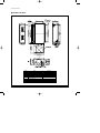
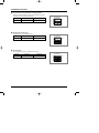
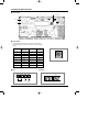
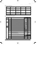
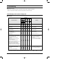
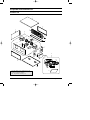
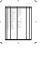
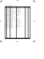
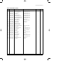
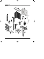
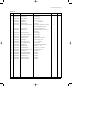
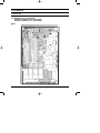
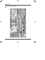
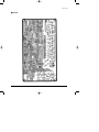
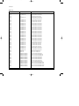
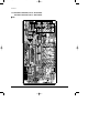
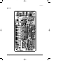
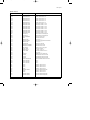
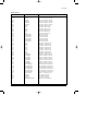
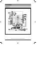
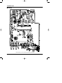
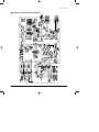
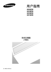
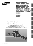
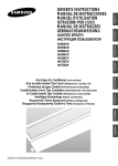
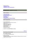
DB98_14452A(3)_CO
5/19/04 3:03 PM
Page 3
DUCT TYPE AIR CONDITIONER
INDOOR UNIT
OUTDOOR UNIT
HH105EZM
HH128EZM
HH140EZM
HH175EZM
HH175ECM
UH105GZM
UH128GZM
UH140GZM
UH175GZM
UH175GCM
SERVICE
Manual
AIR CONDITIONER
CONTENTS
1. Product Specifications
2. Installation
3. Refrigerating Cycle Diagram
4. Set Up the Model Option
5. Troubleshooting
6. Exploded Views and Parts List
7. PCB Diagram
8. Wiring Diagram
9. Schematic Diagram
DB98_14452A(3)_1
5/19/04 3:20 PM
Page 1
1. Product Specifications
1-1 Table
MODEL
INDOOR UNIT
HH105EZM
HH128EZM
HH140EZM
HH175EZM
HH175ECM
OUTDOOR UNIT
UH105GZM
UH128GZM
UH140GZM
UH175GZM
UH175GCM
Btu/h
34,000
43,700
47,800
54,600
56,300
W
10,000
12,800
14,000
16,000
16,500
Btu/h
38,200
47,800
54,600
61,400
64,800
W
11,200
14,000
16,000
18,000
19,000
Cooling
Capacity
Heating
3ø, 380-415V~, 50Hz
Power Supply
Cooling
kW
3.45
4.45
5.12
5.7
6.9
Heating
kW
3.0
5.25
5.97
5.6
6.9
Cooling
A
6.1
7.9
10.6
9.6
12.2
Heating
A
5.35
9.3
12.1
9.4
12.2
H.H
r.p.m
1,000
1,050
1,050
1,000
1,000
Hi
r.p.m
860
1,000
1,000
900
900
Med
r.p.m
760
950
950
800
800
Low
r.p.m
660
900
900
700
700
H.H
m3/min
35
36
36
45
45
Hi
m3/min
29
34
34
39
39
Med
m3/min
23
32
32
33
33
Low
m /min
20
30
30
30
30
Hi
dB(A)
48
49
49
51
51
Med
dB(A)
47
48
48
49
49
Low
dB(A)
46
47
47
48
48
Power Input
Running Current
Fan Speed
(at 0mmAq)
Air
Circulation
(at 14mmAq)
Indoor Unit
Noise Level
(Sound
Pressure)
Heat
Exchanger
3
Type
Wave fin coil
Row x Stages x Fin Pitch
3 x 14 x 1.7(900mm)
Type
Sirocco
Fan
Motor Output
W
-
211
211
-
-
H
mm
390
390
390
390
390
W
mm
1,110
1,110
1,110
1,400
1,400
D
mm
650
650
650
650
650
kg
Net / Gross
66 / 77
66 / 77
66 / 77
75 / 88
75 / 88
Hi
r.p.m.
900
900
900
900
930
Dimensions
Weight
Fan Speed
r.p.m.
500
500
450
500
450
Air Circulation (Hi)
m3/min
-
-
90
90
90
Sound Pressure Level
dB(A)
65
65
65
65
67
114
114
Low
Outdoor Unit
Propeller
Type
Fan
Motor Output
W
-
114
114
Type
Scroll
Model
ZR45KC-TFD ZR61KC-TFD ZR61KC-TFD ZR72KC-TFD ZR81KCE-TFD
Compressor
Samsung Electronics
1
DB98_14452A(3)_1
5/19/04 3:20 PM
Page 2
Table(cont.)
MODEL
INDOOR UNIT
HH105EZM
HH128EZM
HH140EZM
HH175EZM
HH175ECM
OUTDOOR UNIT
UH105GZM
UH128GZM
UH140GZM
UH175GZM
UH175GCM
11.1
14.6
14.6
17.7
19.7
1.122
1.122
3,750
3,850
kW
Capacity
Compressor
Protection
Internal
Type
Wave fin coil
Outdoor Unit
Heat
Exchanger
Row x Stages x Fin Pitch
2 x 48 x 1.7(935 / 915)
m
Face Area
0.756
2
1.122
1.122
Control
Electrical expansion valve
Refrigerant
(R22)Charge
Dimensions
2,200
g
(H x W x D)
mm
968 x 880 x 320
kg
Net / Gross
85 / 90
Weight
4,300
4,300
1,270 x 930 x 385
130 / 140
130 / 140
136 / 146
136 / 146
Condition
Cool(DB/WB)
˚C
27 / 19
Heat(DB/WB)
˚C
20 / 15
Cool(DB/WB)
˚C
35 / 24
Heat(DB/WB)
˚C
7/6
Liquid
mm(inch)
9.52(3/8")
Gas
mm(inch)
19.05(3/4")
Indoor Unit
Outdoor Unit
Pipe O.D.
Size
Piping
Connection Method
Flare
Height
m
Max. 30
Pipe Length
m
Max. 50
Between
Notice : This model is tested under the external static pressure of 14mmAq.
2
Samsung Electronics
DB98_14452A(3)_1
5/19/04 3:20 PM
Page 3
1-2 Dimensions
1-2-1 Indoor Unit
■ HH105EZM / HH128EZM / HH140EZM
(Unit : mm)
Number
Samsung Electronics
Name
Description
1
Liquid pipe connection
ø9.52 Flare
2
Gas pipe connection
ø19.05 Flare
3
Drain pipe connection
OD27.2 ID21.6 (without drain pump)
4
Drain pipe connection
OD29 ID25 (with drain pump)
5
Power supply connection
6
Air discharge flange
7
Air suction flange
8
Hook
For M8~M10
3
DB98_14452A(3)_1
5/19/04 3:20 PM
Page 4
Product Specifications
■ HH175EZM / HH175ECM
(Unit : mm)
Number
4
Name
Description
1
Liquid pipe connection
ø9.52 Flare
2
Gas pipe connection
ø19.05 Flare
3
Drain pipe connection
OD27.2 ID21.6 (without drain pump)
4
Drain pipe connection
OD29 ID25 (with drain pump)
5
Power supply connection
6
Air discharge flange
7
Air suction flange
8
Hook
For M8~M10
Samsung Electronics
DB98_14452A(3)_1
5/19/04 3:20 PM
Page 5
Product Specifications
1-2-2 Outdoor Unit
■ UH105GZM
32
0
968
(Unit : mm)
880
■ UH128GZM / UH140GZM / UH175GZM / UH175GCM
(Unit : mm)
1,270
1,154
385
932
Samsung Electronics
440
415
800
5
DB98_14452A(3)_1
5/19/04 3:20 PM
Page 6
2. Installation
2-1 Assigning Address to Indoor Unit
1. Before installing the indoor unit, assign an address to the indoor unit according to the air conditioning system plan.
2. The address of the indoor unit is assigned by adjusting MAIN(SW02) and RMC(SW01) rotary switches.
K1 K2 K3 K4
SW03
K5 K6 K7 K8
SW04
K9 K10 K11 K12
SW05
SW02 MAIN
SW01 RMC
3. The MAIN address is for communication between the indoor unit and the outdoor unit.
Therefore, you must set it to operate the air conditioner properly.
4. It is required to set the RMC address if you install the wired remote controller and/or the centralized controller.
5. If you install optional accessories such as the wired remote controller, centralized controller, etc. see an appropriate
installation manual.
6. If an optional accessory is not installed, you do not have to set the RMC address. However, adjust K1 and K2 switches of
the SW03 DIP switch to "ON" position in this case.
7. Set the MAIN address by adjusting the rotary switch(SW02) from 0 to F. Each indoor unit connected to the same outdoor
unit must have different address.
7. i. e. If an indoor unit does not have an optional accessory and its
MAIN address is "4".
K1 K2 K3 K4
SW03
K5 K6 K7 K8
SW04
K9 K10 K11 K12
SW05
SW02 MAIN
6
SW01 RMC
Samsung Electronics
DB98_14452A(3)_1
5/19/04 3:20 PM
Page 7
2-2 Additional Functions
■ Compensation for lost temperature in heating operation
■ • Reduces the difference between an actual room temperature and a sensed
■ • temperature by the air conditioner when heating.
Switch No.
Switch ON
Switch OFF
K5
2°C compensation
5°C compensation
K5 K6 K7 K8
SW04
■ Adjusting filter cleaning cycle
■ • You can adjust the cycle for filter sign indicator.
Switch No.
Switch ON
Switch OFF
K6
1000 hours
2000 hours
K5 K6 K7 K8
SW04
■ Hot water heater
■ • You must adjust the K7 when you install the hot water heater.
Switch No.
Switch ON
Switch OFF
K7
No use of hot water heater
Use of hot water heater
Samsung Electronics
K5 K6 K7 K8
SW04
7
DB98_14452A(3)_1
5/19/04 3:20 PM
Page 8
2-3 Setting Up Option Switches
■ Option Switch
Rotary Switch
Display
Key
■ Rotary Switch
■ You should display that how many indoor units are connected to the
outdoor unit. Refer to the table below, then turn the arrow to appropriate
position.
Switch No.
Number of
indoor unit(s)
Switch No.
Number of
indoor unit(s)
0 or 1
One
9
Nine
2
Two
A
Ten
3
Three
B
Eleven
4
Four
C
Twelve
5
Five
D
Thirteen
6
Six
E
Fourteen
7
Seven
F
Fifteen
8
Eight
-
-
■ KEY
■ Display
DIS 1
K1
K2
CHECK MODE
8
K3
RESET
DIS 2
K4
DISPLAY
MODE
SEG 1
SEG 2
SEG 3
SEG 4
Samsung Electronics
DB98_14452A(3)_1
5/19/04 3:20 PM
Page 9
Installation
■ Summary of KEY functions
Function
K1
Number
(Displayed
on SEG 3, 4)
of press times
K2
(Displayed on SEG 3, 4)
K3
(Displayed on SEG 3, 4)
K4
(Displayed on SEG 3, 4)
1
Adding refrigerant at
heating mode
Adding refrigerant at
cooling mode
Reset
Displays data
2
Test operation at
heating mode
Test operation at
cooling mode
-
-
3
End
Pump Down for recovery
of refrigerant
-
-
4
-
End
-
-
✳ Use the K1 only for heat pump models.
■ Reading data indicated on the display
KEY
K1
Number of
press
Item
1
Adding refrigerant for heat pump models
2
Test operation for heat pump models
3
End
1
Adding refrigerant for cooling only models
2
Test operation for cooling only models
3
Pump Down for recovery of refrigerant
4
End
Example
Display
Meaning
K2
K3
Reset
1
2
110 °C
3(1)
Discharge temperature of compressor
4(2)
Temperature of outdoor heat exchanger
38 °C
5(3)
Outdoor temperature
34 °C
6(4)
Step of electronic expansion valve
(0 step : all closed, 480 step : all open)
7(5)
Temperature of evaporator
8(6)
Indoor temperature
K4
120STEP
(12 x 10)
-2 °C
12 °C
22 °C
9
10(7)
✳(
Stopping view mode & display communication data
) is adjusted to HH105EZM/HH128EZM/HH140EZM models.
Samsung Electronics
9
DB98_14452A(3)_1
5/19/04 3:20 PM
Page 10
3. Refrigerating Cycle Diagram
INDOOR UNIT
OUTDOOR UNIT
*Allowable pipe length : Max. 50m
*Allowable drop distance : Max. 30m
EEV
3-Way Valve
Liquid Side
Filter
Filter
Heat
Exchanger
(Condensor)
Heat
Exchanger
(Evaporator)
Gas Side
3-Way Valve
Cooling
Heating
Gas leak check point
10
Muffler
Accumulator
Compressor
High pressure switch
Samsung Electronics
DB98_14452A(3)_1
5/19/04 3:20 PM
Page 11
4. Set Up the Model Option
4-1 Setting Option Setup Method
ex) Option No. :
Step 1 : Enter the Option Setup mode.
1st
Take out the batteries of remote control.
2nd
Press the temp.
button simultaneously and
insert the battery again.
3rd
Make sure the remote control display shown as
.
Step 2 : Enter the Option Setup mode and select your option according to the following procedure.
1
The default value is
Otherwise, push the
.
button to
.
Every time you push the button, the display panel reads
or
repeatedly.
1
2
Push the
2
3
4
button to set the display panel to
.
Every time you push the button, the display panel reads
...
repeatedly.
3
Push the
button to set the display panel to
.
Every time you push the button, the display panel reads
...
repeatedly.
5
6
4
Push the
button to set the display panel to
.
Every time you push the button, the display panel reads
...
repeatedly.
5
Push the
button to set the display panel to
.
Every time you push the button, the display panel reads
...
repeatedly.
✳ Setting is not required if you must
a value which has a
default.
Samsung Electronics
6
Push the
button to set the display panel to
.
Every time you push the button, the display panel reads
...
repeatedly.
11
DB98_14452A(3)_1
5/19/04 3:20 PM
Page 12
Set Up the Model Option
7
Press
button, then the default value is
.
8
Push the
button to set the display panel to
.
Every time you push the button, the display panel reads
...
repeatedly.
7
8
9
9
Push the
button to set the display panel to
.
Every time you push the button, the display panel reads
...
repeatedly.
10
11
10
Push the
12
button to set the display panel to
.
Every time you push the button, the display panel reads
...
repeatedly.
11
Push the
button to set the display panel to
.
Every time you push the button, the display panel reads
...
repeatedly.
12
✳ Setting is not required if you must
a value which has a
default.
Push the
button to set the display panel to
.
Every time you push the button, the display panel reads
...
repeatedly.
Step 3 : Upon completion of the selection, check you made right selections.
Press the Mode Selection key,
to set the display part to and check the display part.
The display part shows
.
Press the Mode Selection key,
The display part shows
to set the display part to
and check the display part.
.
Step 4 : Pressing the ON/OFF button (
)
When pressing the operation ON/OFF key with the direction of remote control for unit, the sound ''Ding'' or ''Diriring'' is
heard and the OPERATION ICON( ) lamp of the display is flickering at the same time, then the input of option is completed. (If the diriring sound isn't heard, try again pressing the ON/OFF button.)
Step 5 : Unit operation test-run
First, Remove the battery from the remote control.
Second, Re-insert the battery into the remote control.
Third, Press ON/OFF button( ) with the direction of remote control for set.
• Error Mode
1st If all lamps of indoor unit are flickering, Plug out, plug in power plug again and press ON/OFF key to retry.
2nd If the unit is not working properly or all lamps are continuously flickering after setting the option code, see if the correct option code is
set up for its model.
12
Samsung Electronics
DB98_14452A(3)_1
5/19/04 3:20 PM
Page 13
Set Up the Model Option
■ OPTION ITEMS
REMOTE
CONTROL SEG1
SEG2
SEG3
SEG4
SEG5
SEG6
SEG7
SEG8
SEG9
SEG10 SEG11 SEG12
MODEL
HH105EZM
0
1
5
4
4
2
1
F
0
0
0
0
HH128EZM
HH140EZM
0
1
5
8
0
0
1
3
0
0
0
0
HH175EZM
HH175ECM
0
1
5
8
0
0
1
4
0
0
0
0
Samsung Electronics
13
DB98_14452A(3)_1
5/19/04 3:20 PM
Page 14
5. Troubleshooting
■ Detection of errors
● If an error occurs during the operation, an LED flickers and the operation is stopped except the LED.
● If you re-operate the air conditioner, it operates normally at first, then detect an error again.
5-1 LED Display on the receiver & display unit
■ LED Display
Indicators
Concealed Type
Abnormal conditions
Operating
Blue
Red
Standard Type
Power reset
Error of temperature sensor in indoor unit
(OPEN/SHORT)
Displayed on appropriate indoor unit
which is operating
Error of heat exchanger sensor in indoor
unit(OPEN/SHORT)
Displayed on appropriate indoor unit
which is operating
Error of outdoor temperature sensor
Error of COND sensor
Error of DISCHARGE sensor
(OPEN/SHORT)
Displayed on appropriate indoor unit
which is operating
Displayed on outdoor unit
1. No communication for 2 minutes between
indoor unit and outdoor unit
(communication error for more than
2 minutes)
1. Error of indoor unit: Displayed on
the indoor unit regardless of
operation
2. Indoor unit receiving the communication
error from outdoor unit
2. Error of outdoor unit: Displayed on
the indoor unit which is operating
3. Outdoor unit tracking 3 minute error
4. When sending the communication error from
outdoor unit the mismatching of the
communication numbers and installed
numbers after completion of tracking. (communication error for more than 2 minutes)
1. Communication error between indoors
(Communication error for more than
2 minutes)
Error of indoor unit: Displayed on the
indoor unit regardless of operation
2. Slave of indoor unit tracking error
- If you turn off the air conditioner when the LED is flickering, the LED is also turned off.
- If you re-operate the air conditioner, it operates normally at first, then detect an error again.
14
: On
: Flickering
: Off
Samsung Electronics
DB98_14452A(3)_1
5/19/04 3:20 PM
Page 15
Toubleshooting
■ LED Display(cont.)
Indicators
Concealed Type
Abnormal conditions
Operating
Blue
Red
Standard Type
1. 2nd detection of high temperature COND
2. 2nd detection of high temperature
DISCHARGE
Displayed on appropriate indoor
unit which is operating
Displayed on outdoor unit
3. Error of reverse phase
Error of float switch
Error of setting option switches for optional
accessories
EEPROM error
EEPROM option error
- If you turn off the air conditioner when the LED is flickering, the LED is also turned off.
- If you re-operate the air conditioner, it operates normally at first, then detect an error again.
Samsung Electronics
: On
: Flickering
: Off
15
DB98_14452A(3)_1
5/19/04 3:20 PM
Page 16
5-2 Outdoor Unit
If an error occurs during the operation, it is displayed on the outdoor unit PCB.
Display
Explanation
High temperature of Discharge (Protection control)
Remark
Error about protection
control of outdoor unit
High temperature of outdoor heat exchanger (Protection control)
COMP DOWN to protect being frozen
Error of momentary power failure (disappears when the unit is Off/On)
Error of OUT TEMP sensor (OPEN/SHORT)
Error of temperature sensor in outdoor heat exchanger (OPEN/SHORT)
Error of Discharge TEMP sensor (OPEN/SHORT)
System Down caused by communication error after completion of tracking
Errors about outdoor unit
sensor (OPEN/SHORT)
Detection during the
operation of indoor unit
(Sensing and sending errors
into the communication data)
Communication and
indoor unit errors
Mismatching of the indoor unit numbers set with those
communicated after completion of tracking
Error of float switch in indoor unit
Error of setting option switches for optional accessories
x
OPEN/SHORT error of room sensor in indoor unit
x
OPEN/SHORT error of eva in sensor in indoor unit
x
EEPROM option error
x
Error of fan starting
Self-diagnosis of indoor and
outdoor unit (x:indoor unit
address)
Displays of operating status
Open error of electronic expansion valve in outdoor unit
(Detected once or more times)
Close error of electronic expansion valve in outdoor unit
(Detected once or more times)
Flicker
Below -5°C when cooling (Outdoor temperature)
Flicker
Over 30°C when heating (Outdoor temperature)
K1, K2, K3, K4,
K5 Flicker
The order of priority : E1 → E2 → E4 → E5 → P0 → P1 → P5 → P6 → t1 → t2 → t3 → tu → to → G4 → G5 → E3 → qx → rx → vx →
K1, K2, K3, K4, K5
The order of priority : - In case that the same error displays from multi-indoor units, the one having the faster address has the priority.
16
Samsung Electronics
DB98_14452A(3)_1
5/19/04 3:20 PM
Page 17
MEMO
Samsung Electronics
17
DB98_14452A(3)_1
5/19/04 3:20 PM
Page 18
6. Exploded Views and Parts List
6-1 Indoor Unit
1
11
6
4
12
12-2
5
12-1
3
12-8
12-3
12-4
12-9
12-6
12-7
7
12-5
10
8
10-1
10-5
11
10-6
2
10-4
10-2
You can search for the updated part code
number through the ITSELF.
10-3
9
URL : http://itself.sec.samsung.co.kr
18
Samsung Electronics
DB98_14452A(3)_1
5/19/04 3:20 PM
Page 19
Exploded Views and Parts List
■
Parts List(HH105EZM)
Code No.
1
DB98-06745A
ASS'Y CABI TOP
HH105EZM, DUCT TYPE
1
2
DB98-06744A
ASS'Y CABI BASE PART
HH105EZM, DUCT TYPE
1
3
DB94-00093A
ASS'Y DRAIN PAN
HH105EZM, DUCT TYPE
1
4
DB96-02934A
ASS'Y EVAP
HH105EZM, DUCT TYPE
1
5
DB32-00016B
THERMISTOR-ASS'Y
HH105EZM, DUCT TYPE
1
6
DB98-05296A
ASS'Y-CABI SIDE LF PART
HH105EZM, DUCT TYPE
1
7
DB72-00499A
INSULATION-CABI SIDE LF B
HH105EZM, DUCT TYPE
1
8
DB72-00498A
INSULATION-CABI SIDE LF A
HH105EZM, DUCT TYPE
1
9
DB63-00080A
COVER-CONTROL
SGCC-M,T0.8
1
10
DB93-01616D
ASS'Y CONTROL IN
220V, 50Hz, HH105EZM
1
10-1
DB61-00098A
CASE-CONTROL
SGCC-M,T0.8
1
10-2
DB26-10065B
TRANS-POWER
230V,50HZ
1
10-3
DB65-00004H
TERMINAL BLOCK-6P
6p
1
10-4
DB65-00004L
TERMINAL BLOCK-6P
6p
1
10-5
DB93-00849L
ASS'Y PCB MAIN-DPM DUCT
DPM,PCB, HH105EZM
1
10-6
DB61-40291B
HOLDER-WIRE
PP,BLK
2
11
DB90-00315A
ASS'Y-BRACKET OUTLET
HH105EZM, DUCT TYPE
2
12
DB94-00222A
ASS'Y BLOWER
HH105EZM, DUCT TYPE
1
12-1
DB31-00145A
MOTOR FAN
OSME-2004SAC(S329)
1
12-2
DB67-00117A
BLOWER LF
SGCC-M
1
12-3
DB90-00313A
ASS'Y-HOUSING
HH105EZM, DUCT TYPE
2
12-4
DB64-00529A
PANEL-DUCT
SGCC-M
1
12-5
DB61-00911A
SUPPORT-MOTOR
SGCC-M,T1.6
1
12-6
DB61-00541A
HOLDER-MOTOR
SGCC-M,W220xL200xT2.0
1
12-7
DB61-20071A
BASE-MOTOR
HH105EZM, DUCT TYPE
1
12-8
DB61-00540A
BRACKET-MOTOR GUIDE
SGCC-M,T1.6
1
12-9
DB67-00117B
BLOWER-RH
SGCC-M
1
Samsung Electronics
Description
Specification
Q'TY
No.
Remark
19
DB98_14452A(3)_1
5/19/04 3:20 PM
Page 20
Exploded Views and Parts List
■
Parts List(HH128EZM / HH140EZM)
Code No.
1
DB98-06745A
ASS'Y CABI TOP
HH140EZM, DUCT TYPE
1
2
DB98-06744A
ASS'Y CABI BASE PART
HH140EZM, DUCT TYPE
1
3
DB94-00093A
ASS'Y DRAIN PAN
HH140EZM, DUCT TYPE
1
4
DB96-02872A
ASS'Y EVAP
HH140EZM, DUCT TYPE
1
5
DB32-00016B
THERMISTOR-ASSY
HH140EZM, DUCT TYPE
1
6
DB98-05296A
ASS'Y-CABI SIDE LF PART
HH140EZM, DUCT TYPE
1
7
DB72-00499A
INSULATION-CABI SIDE LF B
HH140EZM, DUCT TYPE
1
8
DB72-00498A
INSULATION-CABI SIDE LF A
HH140EZM, DUCT TYPE
1
9
DB63-00080A
COVER-CONTROL
SGCC-M,T0.8
1
10
DB93-01616B
ASS'Y CONTROL IN
220V, 50Hz, HH140EZM
1
10-1
DB61-00098A
CASE-CONTROL
SGCC-M,T0.8
1
10-2
DB26-10065B
TRANS-POWER
230V,50HZ
1
10-3
DB65-00004H
TERMINAL BLOCK-6P
6p
1
10-4
DB65-00004L
TERMINAL BLOCK-6P
6p
1
10-5
DB93-00849L
ASS'Y PCB MAIN-DPM DUCT
DPM,PCB, HH140EZM
1
10-6
DB61-40291B
HOLDER-WIRE
PP,BLK
2
11
DB90-00315A
ASS'Y-BRACKET OUTLET
HH140EZM, DUCT TYPE
2
12
DB94-00222B
ASS'Y BLOWER
HH140EZM, DUCT TYPE
1
12-1
DB31-00079E
MOTOR FAN
OSM-1604SAC(S324)
1
12-2
DB67-00117A
BLOWER LF
SGCC-M
1
12-3
DB90-00313A
ASS'Y-HOUSING
HH140EZM, DUCT TYPE
2
12-4
DB64-00529A
PANEL-DUCT
SGCC-M
1
12-5
DB61-00911A
SUPPORT-MOTOR
SGCC-M,T1.6
1
12-6
DB61-00541A
HOLDER-MOTOR
SGCC-M,W220xL200xT2.0
1
12-7
DB61-20071A
BASE-MOTOR
HH140EZM, DUCT TYPE
1
12-8
DB61-00540A
BRACKET-MOTOR GUIDE
SGCC-M,T1.6
1
12-9
DB67-00117B
BLOWER-RH
SGCC-M
1
20
Description
Specification
Q'TY
No.
Remark
Samsung Electronics
DB98_14452A(3)_1
5/19/04 3:20 PM
Page 21
Exploded Views and Parts List
■
Parts List(HH175EZM / HH175ECM)
Description
Specification
Q'TY
No.
Code No.
1
DB98-05295A
ASS'Y CABI TOP
HH175EZM, DUCT TYPE
1
2
DB98-05294A
ASS'Y CABI BASE PART
HH175EZM, DUCT TYPE
1
3
DB94-00184A
ASS'Y DRAIN PAN
HH175EZM, DUCT TYPE
1
4
DB96-02634B
ASS'Y EVAP
HH175EZM, DUCT TYPE
1
5
DB32-00016B
THERMISTOR-ASSY
HH175EZM, DUCT TYPE
1
6
DB98-05296A
ASS'Y-CABI SIDE LF PART
HH175EZM, DUCT TYPE
1
7
DB72-00499A
INSULATION-CABI SIDE LF B
HH175EZM, DUCT TYPE
1
8
DB72-00498A
INSULATION-CABI SIDE LF A
HH175EZM, DUCT TYPE
1
9
DB63-00080A
COVER-CONTROL
SGCC-M, T0.8
1
10
DB93-01616A
ASS'Y CONTROL IN
220V, 50Hz, HH175EZM
1
10-1
DB61-00098A
CASE-CONTROL
SGCC-M, T0.8
1
10-2
DB26-10065B
TRANS-POWER
230V, 50Hz
1
10-3
DB65-00004H
TERMINAL BLOCK-6P
6P
1
10-4
DB65-00004L
TERMINAL BLOCK-6P
6P
1
10-5
DB93-00849D
ASS'Y PCB MAIN-DPM DUCT
DPM, PCB, HH175EZM
1
10-6
DB61-40291B
HOLDER-WIRE
PP, BLK
2
11
DB90-00751A
ASS'Y-BRACKET OUTLET
HH175EZM, DUCT TYPE
2
12
DB94-00193A
ASS'Y BLOWER
HH175EZM, DUCT TYPE
1
12-1
DB31-00142A
MOTOR FAN
OSME-3751SAC(S325)
1
12-2
DB67-00206A
BLOWER LF
SGCC-M
1
12-3
DB94-00185A
ASS'Y-HOUSING
HH175EZM, DUCT TYPE
2
12-4
DB64-00495A
PANEL-DUCT
SGCC-M
1
12-5
DB61-00911A
SUPPORT-MOTOR
SGCC-M, T1.6
1
12-6
DB61-00541A
HOLDER-MOTOR
SGCC-M, W220xL200xT2.0
1
12-7
DB61-20071A
BASE-MOTOR
HH175EZM, DUCT TYPE
1
12-8
DB61-00919A
BRACKET-MOTOR GUIDE
SGCC-M, T1.6
1
12-9
DB67-00206B
BLOWER-RH
SGCC-M
1
Samsung Electronics
Remark
21
DB98_14452A(3)_1
5/19/04 3:20 PM
Page 22
6-2 Outdoor Unit
■ UH105GZM
1
2
3
9
6
26
4
23
24
5
7
8
25
22
21
19
20
14
18
12
17
10
16
13
11
15
22
Samsung Electronics
DB98_14452A(3)_1
5/19/04 3:20 PM
Page 23
Exploded Views and Parts List
■
Parts List
Description
Specification
Q'TY
No.
Code No.
1
DB90-01029B
ASS'Y CABINET-TOP
UH105GZM, ASS'Y(SECC-P)
1
2
DB61-01348A
GUIDE-SCREEN
RVMPC035B2M0
1
3
DB96-02724A
ASS'Y COND-UNIT
UH105GZM, 2x36
1
4
DB32-00021H
THERMISTOR
-,10Kohm,-,-20~100,-,-,-,-,-
1
5
DB32-00071A
THERMISTOR
-,-,-,-,-,-,-,-,RFPC020B2M0
1
6
DB61-01173B
BRACKET MOTOR
UH105GZM,-,-,-,-,-,-
1
7
DB31-00060P
MOTOR FAN-OSMED-1166SRC
OSME1166SRC, FAN MOTOR, 1.03/0.58,50
1
Remark
210/115,220,900/500,50,220,75deg, -,8
DB67-00140A
FAN-PROPELLER
AS+GF 20%,BLK,OD460,B-PJT
1
9
DB64-00857A
CABINET-BACK LF
RVMC035B2M0,SECCP,T1.0,W81,L947,-
1
WHITE GRAY,10
DB90-01026A
ASS'Y-CABI FRONT LF
RVMPC035B2M0
1
11
DB90-01224A
ASS'Y CABINET FRONT-RH
UH105GZM,ASS'Y
1
12
DB94-00319A
ASS'Y PARTITION-OUT
RVMPC035B2M0
1
13
DB90-01222A
ASS'Y-WIRE PLATE
UH105GZM,SECC-P,SC-90073T
1
14
DB61-00152A
CASE-PCB-OUT
AE-240E,T2.5,ABS,-,-,BLK,-
1
15
DB93-02266A
ASS'Y CONTROL OUT
HP,-,-,-,-,-,-,UH105GZM
1
16
DB90-01223A
ASS'Y CABINET BACK-RH
UH105GZM,ASS'Y
1
17
DB90-01030B
ASS'Y BASE OUT
UH105GZM,DPM 3.5HP OUTDOOR
1
18
DB73-10023A
GROMMET-COMP
-,EPDM,T41,-,-,-,-,BLK,-
4
19
DB72-00237A
INSULATION-SOUND
T12,W630,L390,-,-,-,ACH3600G
1
20
DB95-00435A
ASS'Y-DIGITAL SCROLL COMP
UH105GZM,ZR45KC-TFD
1
21
DB62-02004A
TUBE-SUCTION
-,UH105GZM,-,-,-,-,-
1
22
DB96-02692A
ASS'Y TUBE-DISCHARGE
UH105GZM,-
1
23
DB96-02693A
ASS'Y-EXPANSION VALVE
UH105GZM,-
1
24
DB96-02694A
ASS'Y-4WAY VALVE
UH105GZM,-
1
25
DB96-02695A
ASS'Y-ACCUMULATOR
UH105GZM,-
1
26
DB96-02697A
ASS'Y-VALVE SERVICE
UH105GZM,-
1
Samsung Electronics
23
DB98_14452A(3)_1
5/19/04 3:20 PM
Page 24
Exploded Views and Parts List
■ UH128GZM / UH140GZM
26
7
8
2
24
1-1
25
1
9
11
6
20
4
3
13
11-1
11-2
19
12-1
10
19-4
12-2
19-3
19-5
12
5
19-1
14
21
19-6
14-3
17
19-2
16
19-7
22
14-1
14-5
15
15-1
14-2
14-4
15-2
23
18
24
Samsung Electronics
DB98_14452A(3)_1
5/19/04 3:20 PM
Page 25
Exploded Views and Parts List
■
Parts List
No.
Code No.
Description
Specification
Q'TY
1
DB90-00250A
CABINET FRONT
ASS'Y CABINET FRONT
1
1-1
DB68-10612A
LABEL SAMSUNG
HARD PC, T0.5
1
2
DB90-00551A
ASS'Y CABI BACK-LF
ASS'Y CABINET BACK LF
1
3
DB67-50067A
FAN-PROPELLER
ABS+GF20,D495,4BLADE
2
4
DB31-00060L
MOTOR FAN
OSME-1156SRC,(S542)
1
5
DB31-00060M
MOTOR FAN
OSME-1156SRC,(S543)
1
6
DB61-00837A
BRACKET MOTOR
SGCC-M,T1.6
1
7
DB61-00398A
SUPPORTER-MOTOR
SGCC-M,T1.6
1
8
DB61-30615A
SUPPORTER-FRAME
SGCC-M,T1.2
1
9
DB67-30025A
PARTITION
SBHG1,T1
1
10
DB61-30365A
SUPPORTER-COND
SBHG1,T1.6
1
11
DB96-01259D
ASS'Y COND-UP
ASS'Y COND_UP
1
11-1
DB96-01052A
ASS'Y-COLLECTOR IN UP
CU, COLLECTOR IN UP
1
11-2
DB96-01056A
ASS'Y-COLLECTOR OUT UP
CU, COLLECTOR OUT UP
1
12
DB96-01258F
ASS'Y COND-LOW
ASS'Y COND_LOW
1
12-1
DB96-01053A
ASS'Y COLLECTOR IN LOW
UH140GZM,IN LOW
1
12-2
DB96-01057A
ASS'Y-COLLECTOR OUT LOW
UH140GZM,OUT LOW
1
13
DB61-30358B
SUPPORTER-UNIT OUT
SGCC-A,T1.2
1
14
DB96-02302A
ASS'Y-4WAY VALVE
UH140GZM, 4-WAY VALVE
1
14-1
DB33-00003J
SOLENOID VALVE
SAGINOMIYA
1
14-2
DB34-00021B
SWITCH-HIGH PRESSURE
220-240V,1~4A,33kgf/cm G
1
14-3
DB62-40019A
VALVE-4WAY
3/4INCH
1
14-4
DB62-40092A
VALVE-SERVICE
C3604,30KG/CM2G
1
2
14-5
DB67-00197A
MUFFLER
UH140GZM
1
15
DB96-02515A
ASS'Y-VALVE EXPANSION
UH140GZM,4WAY_CASSETTE_48K
1
15-1
DB62-00720A
VALVE EXPAN-ELEC.
EDM-50YH
1
15-2
DB62-40011F
VALVE-SERVICE
3/8 INCH
1
16
DB96-01055A
ASS'Y-ACCUMULATOR
UH140GZM,ACCUM
1
17
DB95-10057J
ASS'Y-COMP-SCROLL
ZR61KC-TFD
1
18
DB95-30013V
ASS'Y HEATER-COMP
UH140GZM
1
19
DB93-01156D
ASS'Y CONTROL OUT
UH140GZM
1
19-1
PE-DPM5HP-05
ASS'Y PCB PARTS
PE-DPM5HP-05
1
19-2
3601-000438
FUSE-CARTRIDGE
250V,15A,SLOW-BLOW,CERAMIC,6.35x31.8mm
1
19-3
DB26-10070A
TRANS-POWER
DC17,AC230,DC17,DC0.6A
1
19-4
DB34-90090A
SWITCH-MAGNET
FURNAS,-,3P+1P,APH450PG,42AF35
1
19-5
DB61-00152A
CASE-PCB-OUT
AE-240E,T2.5,ABS,BLK
1
19-6
DB65-00074C
TERMINAL BLOCK-8P
UH140GZM
1
19-7
DB65-40062L
TERMINAL BLOCK-2P
UH140GZM
1
20
DB32-00021E
THERMISTOR-ASS'Y OUT
103AT,-20~+100,-,5V
1
21
DB72-00560B
INSULATION-SOUND TOP
MUF-0911,FELT,T12
1
22
DB72-00560A
INSULATION-SOUND
MUF-0911,FELT,T12
1
23
DB90-00247C
ASS'Y BASE OUT
UH140GZM
1
24
DB90-00550A
ASS'Y CABI BACK-RH
UH140GZM
1
25
DB90-00144A
ASS'Y COVER-CONTROL
ASM-3500A
1
26
DB90-00626A
ASS'Y CABI-TOP
UH140GZM
1
Samsung Electronics
25
DB98_14452A(3)_1
5/19/04 3:20 PM
Page 26
Exploded Views and Parts List
■ UH175GZM / UH175GCM
24
7
2
8
22
1-1
23
1
9
11
6
4
3
13
19
11-1
11-2
18
12-1
10
18-4
12-2
18-3
12
5
18-5
20
18-1
14
18-6
18-2
16
14-3
14-1
14-6
14-5
14-2
18-7
15
15-1
21
14-4
15-2
17
26
Samsung Electronics
DB98_14452A(3)_1
5/19/04 3:20 PM
Page 27
Exploded Views and Parts List
■
Parts List
No.
Code No.
Description
Q'TY
Specification
UH175GCM UH175GZM
1
1-1
2
3
4
5
6
7
8
9
10
11
11-1
11-2
12
12-1
12-2
13
14
14-1
14-2
14-3
14-4
14-5
14-6
15
15-1
15-2
16
17
18
18-1
18-2
18-3
18-4
18-5
18-6
18-7
19
20
21
22
23
24
DB90-00250A
DB68-10612A
DB90-00551A
DB67-50067A
DB31-00060L
DB31-00060M
DB61-00837A
DB61-00398A
DB61-30615A
DB67-30025A
DB61-30365A
DB96-01259D
DB96-01052A
DB96-01056A
DB96-01258D
DB96-01053A
DB96-01057A
DB61-30358B
DB96-02226A
DB96-02674A
DB33-00003J
DB34-00021B
DB62-40019A
DB62-00450A
DB62-40092A
DB67-00197A
DB67-10042A
DB96-02241A
DB96-02819A
DB62-01251A
DB62-00811A
DB62-00425A
DB62-40011F
DB95-00336A
DB95-00418A
DB95-30013S
DB93-01156C
DB93-02074A
DB93-02343A
3601-000438
DB26-10070A
3501-001231
DB61-00152A
DB65-00074C
DB65-40062L
DB32-00021E
DB62-01793A
DB90-00247A
DB90-01125A
DB90-00144A
DB90-00626A
Samsung Electronics
CABINET FRONT
LABEL SAMSUNG
ASS'Y CABI BACK-LF
FAN-PROPELLER
MOTOR FAN
MOTOR FAN
BRACKET MOTOR
SUPPORTER-MOTOR
SUPPORTER-FRAME
PARTITION
SUPPORTER-COND
ASS'Y COND-UP
ASS'Y-COLLECTOR IN UP
ASS'Y-COLLECTOR OUT UP
ASS'Y COND-LOW
ASS'Y COLLECTOR IN LOW
ASS'Y COLLECTOR OUT LOW
SUPPORTER-UNIT OUT
ASS'Y-4-WAY VALVE
ASS'Y-4-WAY VALVE
SOLENOID VALVE
SWITCH-HIGH RRESSURE
VALVE-4WAY
VALVE-SERVICE
VALVE-SERVICE
MUFFLER
ACCUMULATOR
ASS'Y-VALVE EXPANSION
ASS'Y-VALVE EXPANSION
VALVE EXPAN-ELEC
VALVE EXPAN-ELEC
VALVE-SERVICE
VALVE-SERVICE
ASS'Y-COMP-SCROLL
ASS'Y-COMP-SCROLL
ASS'Y HEATER-COMP
ASS'Y CONTROL OUT
ASS'Y PCB PARTS
ASS'Y PCB PARTS
FUSE-CARTRIDGE
TRANS-POWER
SWITCH-MAGNET
CASE-PCB-OUT
TERMINAL BLOCK-8P
TERMINAL BLOCK-2P
THERMISTOR-ASSY OUT
INSULATION-COMP SOUND
ASS'Y BASE OUT
ASS'Y CABI BACK-RH
ASS'Y COVER-CONTROL
ASS'Y CABI-TOP
ASS'Y CABINET FRONT
HARD PC, T0.5
ASS'Y CABINET BACK LF
ABS+GF20, D495, 4BLADE
ASME-1156SRC, (S542)
ASME-1156SRC, (S543)
SGCC-M, T1.6
SGCC-M, T1.6
SGCC-M, T1.2
SBHG1, T1.0
SBHG1, T1.6
ASS'Y COND-UP
CU, COLLECTOR IN UP
CU, COLLECTOR OUT UP
ASS'Y COND-LOW
UH175GCM, IN LOW
UH175GCM, OUT LOW
SGCC-A, T1.2
UH175GCM, 4-WAY VALVE
UH175GZM, 4-WAY VALVE
SAGINOMIYA
220-240, 1~4A, 33KGF/øG
3/4 INCH
C3604, 30KG/CM2G
C3604, 30KG/CM2G
UH175GCM
UH175GCM, ACCUM
UH175GCM, 4WAY-CASSETTE-48K
UH175GZM, 4WAY-CASSETTE-48K
EDM-60YP
EDM-60YH
3/8 INCH
3/8 INCH
ZR72KC-TFD
ZR72KC-TFD
UH175GCM
UH175GCM/UH175GZM
PE-DPM5HP-03
PE-DPM5HP-06
250V, 15A, SLOW-BLOW, CERAMIC, 6.35x31.8mm
DC17, AC230, DC17, DC0.6A
220V, 50Hz, UH175GCM
AE-240E, T2.5, ABS, BLK
UH175GCM
UH175GCM
103AT, -20~+100, -, 5V
MUF-0911, FEKTM T12
UH175GCM
UH175GCM
ASM-3500A
UH175GCM
1
1
1
2
1
1
1
1
1
1
1
1
1
1
1
1
1
1
1
1
1
1
1
1
1
1
1
1
1
1
1
1
1
1
1
1
1
1
1
1
1
1
1
1
1
1
1
2
1
1
1
1
1
1
1
1
1
1
1
1
1
1
1
1
1
1
1
1
1
1
1
1
1
1
1
1
1
1
1
1
1
1
1
1
1
1
1
1
27
DB98_14452A(3)_1
5/19/04 3:20 PM
Page 28
7. PCB Diagram
7-1 Indoor Unit
7-1-1 HH105EZM(Code No : DB93-00849M)
7-1-1 HH128EZM / HH140EZM(Code No : DB93-00849L)
7-1-1 HH175EZM / HH175ECM(Code No : DB93-00849D)
■ TOP
28
Samsung Electronics
DB98_14452A(3)_1
5/19/04 3:20 PM
Page 29
PCB Diagram
■ BOTTOM
Samsung Electronics
29
DB98_14452A(3)_1
5/19/04 3:20 PM
Page 30
PCB Diagram
■
Parts List
Location No.
Description
Specification
BD71
DIODE BRIDGE
DF06S
C101
C-ELEC
2200uF 35V
C102
C-CHIP
CS2012Y 5V 104Z5
C103
C-ELEC
2200uF 25V
C104
C-CHIP
CS2012Y 5V 104Z5
C105
C-ELEC
SD 470uF,25V
C201
C-CHIP
CS2012Y 5V 104Z5
C202
C-CHIP
CS2012Y 5V 104Z5
C203
C-CHIP
CS2012Y 5V 104Z5
C204
C-CHIP
CS2012 5V 103Z5
C205
C-CHIP
CS2012 5V 103Z5
C301
C-CHIP
CS2012 5V 103Z5
C302
C-CHIP
CS2012Y 5V 104Z5
C303
C-CHIP
CS2012Y 5V 104Z5
C304
C-CHIP
CS2012Y 5V 104Z5
C305
C-CHIP
CS2012Y 5V 104Z5
C306
C-CHIP
CS2012Y 5V 104Z5
C311
C-CHIP
CS2012 5V 103Z5
C312
C-CHIP
CS2012Y 5V 104Z5
C313
C-CHIP
CS2012Y 5V 104Z5
C314
C-CHIP
CS2012Y 5V 104Z5
C315
C-CHIP
CS2012Y 5V 104Z5
C316
C-CHIP
CS2012Y 5V 104Z5
C401
C-CHIP
CS2012Y 5V 104Z5
C402
C-CHIP
CS2012Y 5V 104Z5
C403
C-CHIP
CS2012Y 5V 104Z5
C413
C-CHIP
CS2012Y 5V 104Z5
C501
C-CHIP
CS2012Y 5V 104Z5
C502
C-CHIP
CS2012Y 5V 104Z5
C503
C-CHIP
CS2012Y 5V 104Z5
C504
C-CHIP
CS2012Y 5V 104Z5
C505
C-CHIP
CS2012Y 5V 104Z5
C506
C-CHIP
CS2012Y 5V 104Z5
C508
C-CHIP
CS2012Y 5V 104Z5
C509
C-CHIP
CS2012Y 5V 104Z5
C510
C-CHIP
CS2012Y 5V 104Z5
C511
C-CHIP
CS2012Y 5V 104Z5
C901
C-CHIP
CS2012X 7R 102K5
C902
C-CHIP
CS2012Y 5V 104Z5
C910
C-FILM
2A 472J
C911
C-CHIP
CS2012 5V 103Z5
C912
C-CHIP
CS2012 5V 103Z5
C913
C-CHIP
CS2012 5V 103Z5
C914
C-CHIP
CS2012 5V 103Z5
C915
C-CHIP
CS2012 5V 103Z5
C917
C-CHIP
CS2012Y 5V 104Z5
30
Samsung Electronics
DB98_14452A(3)_1
5/19/04 3:20 PM
Page 31
PCB Diagram
■
Parts List(cont.)
Location No.
Description
Specification
CD31
DIODE-TVS
SAC5.0
CD32
DIODE-TVS
SAC5.0
CD33
DIODE-TVS
SAC5.0
CD34
DIODE-TVS
SAC5.0
CN11
CONNECTOR
SMW250-03 RED
CN31
CONNECTOR
YW396-02V RED
CN32
CONNECTOR
YW396-02V WHT
CN33
CONNECTOR
YW396-02V BLU
CN41
CONNECTOR
SMW250-04 WHT
CN51
CONNECTOR
SMW250-02 BLK
CN71
CONNECTOR
YW396-03AV BLU
CN72
CONNECTOR
YW396-03AV WHT
CN73
CONNECTOR
YW396-09AV WHT
CN74
CONNECTOR
YW396-03AV YEL
CN75
CONNECTOR
YW396-03 BLK
CN77
CONNECTOR
YW396-03 RED
CN91
CONNECTOR
SMW200-11 WHT
D105
DIODE-RECT
IN4007
D900
DIODE
4148M
D901
DIODE
4148M
D902
DIODE
4148M
D903
DIODE
4148M
D904
DIODE
4148M
D905
DIODE
4148M
D906
DIODE
4148M
D907
DIODE
4148M
D908
DIODE
4148M
D909
DIODE
4148M
D910
DIODE
4148M
D911
DIODE
4148M
D912
DIODE
4148M
D913
DIODE
4148M
D914
DIODE
4148M
D915
DIODE
4148M
D916
DIODE
4148M
D917
DIODE
4148M
D918
DIODE
4148M
D919
DIODE
4148M
F701
FUSE
250V, 5A
F701
HOLDER FUSE
FB58-20
F702
FUSE
250V, 1A
FT71
FILTER NOISE
HP1-P10
IC01
HEAT SINK
A6063,L25.5 W15,WHT
IC01
IC VOLT REGULATOR
KA7812A
IC01
SCREW-TAPPING
PH,M3,L8,FE FZY
IC02
IC VOLT REGULATOR
KA7805A
Samsung Electronics
31
DB98_14452A(3)_1
5/19/04 3:20 PM
Page 32
PCB Diagram
■
Parts List(cont.)
Location No.
Description
Specification
IC03
IC-RESET
IC04
IC - MCU
MB89635
IC05
IC DRIVE
ULN2003AFW
IC06
IC DRIVE
ULN2003AFW
IC07
IC DRIVE
ULN2003AFW
IC18
IC-BUS TRANSCEIVER
MAX485
IC19
IC-BUS TRANSCEIVER
MAX485
IC51
EEPROM
93LC56B-1/SN
LED01
LED LAMP
SY5511 YEL
LED02
LED LAMP
SR5511 RED
Q201
TR SMALL SIGNAL
2SC2412K
Q202
TR SMALL SIGNAL
2SC2412K
Q601
TR SMALL SIGNAL
2SC2412K
Q602
TR SMALL SIGNAL
2SC2412K
Q603
TR SMALL SIGNAL
MMST2907A
Q901
TR DIGITAL
DTA114EKA
Q902
TR DIGITAL
DTA114EKA
Q903
TR DIGITAL
DTA114EKA
R04
R-CHIP
R2012 1kΩ±5
R201
R-CHIP
R2012 1kΩ±5
R202
R-CHIP
R2012 3.3kΩ±5
R203
R-CHIP
R2012 10kΩ±5
R204
R-CHIP
R2012 1kΩ±5
R205
R-CHIP
R2012 1kΩ±5
R206
R-CHIP
R2012 1kΩ±5
R302
R-CHIP
R2012 10kΩ±5
R303
R-CHIP
R2012 10kΩ±5
R312
R-CHIP
R2012 10kΩ±5
R313
R-CHIP
R2012 10kΩ±5
R401
R-CHIP
R2012 6.8kΩ±1
R402
R-CHIP
R2012 6.8kΩ±1
R403
R-CHIP
R2012 6.8kΩ±1
R404
R-CHIP
R2012 330Ω±5
R405
R-CHIP
R2012 330Ω±5
R406
R-CHIP
R2012 330Ω±5
R413
R-CHIP
R2012 24kΩ±1
R416
R-CHIP
R2012 330Ω±5
R501
R-CHIP
R2012 10kΩ±5
R502
R-CHIP
R2012 330Ω±5
R503
R-CHIP
R2012 10kΩ±5
R504
R-CHIP
R2012 47kΩ±5
R505
R-CHIP
R2012 47kΩ±5
R601
R-CHIP
R2012 1kΩ±5
R602
R-CHIP
R2012 10kΩ±5
R603
R-CHIP
R2012 1kΩ±5
R604
R-CHIP
R2012 470Ω±5
32
KA7533Z
Samsung Electronics
DB98_14452A(3)_1
5/19/04 3:20 PM
Page 33
PCB Diagram
■
Parts List(cont.)
Location No.
Description
Specification
R605
R-CHIP
R607
R-CHIP
R2012 1kΩ±5
R608
R-CHIP
R2012 10kΩ±5
R609
R-CHIP
R2012 10kΩ±5
R610
R-CHIP
R2012 3.3kΩ±5
R813
R-CHIP
R2012 1kΩ±5
R814
R-CHIP
R2012 1kΩ±5
R815
R-CHIP
R2012 1kΩ±5
R816
R-CHIP
R2012 1kΩ±5
R901
R-CHIP
R2012 330Ω±5
R902
R-CHIP
R2012 1kΩ±5
R903
R-CHIP
R2012 10kΩ±5
R911
R-CHIP
R2012 10kΩ±5
R912
R-CHIP
R2012 10kΩ±5
R913
R-CHIP
R2012 10kΩ±5
R914
R-CHIP
R2012 10kΩ±5
R915
R-CHIP
R2012 10kΩ±5
RY70
RELAY
JQ1a-12V
RY71
RELAY
JQ1a-12V
RY74
RELAY
JQ1a-12V
RY75
RELAY
CS11-12SH
RY76
RELAY
CS11-12SH
RY77
RELAY
CS11-12SH
RY78
RELAY
CS11-12SH
SW01
DIGITAL-SWITCH
PT65 103
SW02
DIGITAL-SWITCH
PT65 503
SW03
DIP-SWITCH
BSD-104
SW04
DIP-SWITCH
BSD-104
SW05
DIP-SWITCH
BSD-104
VA71
VARISTOR
INR14D561K-BS
X301
RESONATOR
10MHz
Samsung Electronics
R2012 470Ω±5
33
DB98_14452A(3)_1
5/19/04 3:20 PM
Page 34
7-2 Outdoor Unit
7-2-1 UH105GZM(Code No : DB93-01885A)
■ TOP
34
Samsung Electronics
DB98_14452A(3)_1
5/19/04 3:20 PM
Page 35
PCB Diagram
■ BOTTOM
Samsung Electronics
35
DB98_14452A(3)_1
5/19/04 3:20 PM
Page 36
PCB Diagram
■
Parts List
Location No.
Description
Specification
C101
C-AL
1000uF,20%,35V,GP,TP,13x25,5
C102
C-CERAMIC,CHIP
100nF,+80-20%,50V,Y5V,TP,2012
C103
C-AL
1000uF,20%,35V,GP,TP,13x25,5
C104
C-CERAMIC,CHIP
100nF,+80-20%,50V,Y5V,TP,2012
C105
C-AL
470uF,20%,25V,GP,TP,10x12.5mm
C201
C-CERAMIC,CHIP
100nF,+80-20%,50V,Y5V,TP,2012
C202
C-CERAMIC,CHIP
10nF,+80-20%,50V,Y5V,TP,2012
C301
C-CERAMIC,CHIP
10nF,+80-20%,50V,Y5V,TP,2012
C302
C-CERAMIC,CHIP
100nF,+80-20%,50V,Y5V,TP,2012
C303
C-CERAMIC,CHIP
100nF,+80-20%,50V,Y5V,TP,2012
C304
C-CERAMIC,CHIP
100nF,+80-20%,50V,Y5V,TP,2012
C305
C-CERAMIC,CHIP
100nF,+80-20%,50V,Y5V,TP,2012
C306
C-CERAMIC,CHIP
100nF,+80-20%,50V,Y5V,TP,2012
C307
C-CERAMIC,CHIP
100nF,+80-20%,50V,Y5V,TP,2012
C308
C-CERAMIC,CHIP
100nF,+80-20%,50V,Y5V,TP,2012
C401
C-CERAMIC,CHIP
100nF,+80-20%,50V,Y5V,TP,2012
C402
C-CERAMIC,CHIP
100nF,+80-20%,50V,Y5V,TP,2012
C403
C-CERAMIC,CHIP
100nF,+80-20%,50V,Y5V,TP,2012
C503
C-CERAMIC,CHIP
100nF,+80-20%,50V,Y5V,TP,2012
C504
C-CERAMIC,CHIP
100nF,+80-20%,50V,Y5V,TP,2012
C505
C-CERAMIC,CHIP
100nF,+80-20%,50V,Y5V,TP,2012
C801
C-CERAMIC,CHIP
100nF,+80-20%,50V,Y5V,TP,2012
C802
C-CERAMIC,CHIP
100nF,+80-20%,50V,Y5V,TP,2012
C803
C-CERAMIC,CHIP
100nF,+80-20%,50V,Y5V,TP,2012
C804
C-CERAMIC,CHIP
100nF,+80-20%,50V,Y5V,TP,2012
C901
C-CERAMIC,CHIP
10nF,+80-20%,50V,Y5V,TP,2012
C902
C-CERAMIC,CHIP
10nF,+80-20%,50V,Y5V,TP,2012
C903
C-CERAMIC,CHIP
10nF,+80-20%,50V,Y5V,TP,2012
C904
C-CERAMIC,CHIP
10nF,+80-20%,50V,Y5V,TP,2012
C905
C-CERAMIC,CHIP
100nF,+80-20%,50V,Y5V,TP,2012
C906
C-CERAMIC,CHIP
100nF,+80-20%,50V,Y5V,TP,2012
C907
C-CERAMIC,CHIP
100nF,+80-20%,50V,Y5V,TP,2012
CD31
DIODE-TVS
SAC5.0,7.6/-/-V,500W,DO-15
CD32
DIODE-TVS
SAC5.0,7.6/-/-V,500W,DO-15
CN11
CONNECTOR-HEADER
BOX,3P,1R,2.5mm,STRAIGHT,SN
CN12
CONNECTOR-HEADER
1WALL,2P,1R,3.96mm,STRAIGHT,SN
CN31
CONNECTOR-HEADER
1WALL,2P,1R,3.96mm,STRAIGHT,SN
CN41
CONNECTOR-HEADER
BOX,4P,1R,2.5mm,STRAIGHT,SN
CN42
CONNECTOR-HEADER
BOX,2P,1R,2.5mm,STRAIGHT,SN
CN60
CONNECTOR-HEADER
BOX,6P,1R,2.5mm,STRAIGHT,SN
CN61
CONNECTOR-HEADER
BOX,5P,1R,2.5mm,STRAIGHT,SN
CN70
CONNECTOR-HEADER
BOX,1P,1R,6mm,STRAIGHT,NI,WHT
CN71
CONNECTOR-HEADER
1WALL,2P,1R,7.92mm,STRAIGHT,SN,BL
CN72
CONNECTOR-HEADER
1WALL,3P,1R,7.92mm,STRAIGHT,SN,BL
CN73
CONNECTOR-HEADER
1WALL,3P,1R,7.92mm,STRAIGHT,SN,WH
CN74
CONNECTOR-HEADER
1WALL,2P,1R,7.92mm,STRAIGHT,SN,YE
36
Samsung Electronics
DB98_14452A(3)_1
5/19/04 3:20 PM
Page 37
PCB Diagram
■
Parts List(cont.)
Location No.
Description
Specification
CN75
CONNECTOR-HEADER
1WALL,4P,1R,7.92mm,STRAIGHT,SN,WH
CN76
CONNECTOR-HEADER
1WALL,3P,1R,7.92mm,STRAIGHT,SN,YE
CN77
CONNECTOR-HEADER
1WALL,2P,1R,7.92mm,STRAIGHT,SN,WH
D101
DIODE-RECTIFIER
1N4007,1000V,1A,DO-41,TP
D102
DIODE-RECTIFIER
1N4007,1000V,1A,DO-41,TP
D103
DIODE-RECTIFIER
1N4007,1000V,1A,DO-41,TP
D104
DIODE-RECTIFIER
1N4007,1000V,1A,DO-41,TP
D105
DIODE-RECTIFIER
1N4007,1000V,1A,DO-41,TP
D106
DIODE-RECTIFIER
1N4007,1000V,1A,DO-41,TP
D107
DIODE-RECTIFIER
1N4007,1000V,1A,DO-41,TP
D108
DIODE-RECTIFIER
1N4007,1000V,1A,DO-41,TP
D201
DIODE-SWITCHING
RLS4148,100V,200MA,SOD-80C,TP
D901
DIODE-SWITCHING
RLS4148,100V,200MA,SOD-80C,TP
D902
DIODE-SWITCHING
RLS4148,100V,200MA,SOD-80C,TP
D903
DIODE-SWITCHING
RLS4148,100V,200MA,SOD-80C,TP
D904
DIODE-SWITCHING
RLS4148,100V,200MA,SOD-80C,TP
D905
DIODE-SWITCHING
RLS4148,100V,200MA,SOD-80C,TP
D906
DIODE-SWITCHING
RLS4148,100V,200MA,SOD-80C,TP
D907
DIODE-SWITCHING
RLS4148,100V,200MA,SOD-80C,TP
D908
DIODE-SWITCHING
RLS4148,100V,200MA,SOD-80C,TP
D909
DIODE-SWITCHING
RLS4148,100V,200MA,SOD-80C,TP
D910
DIODE-SWITCHING
RLS4148,100V,200MA,SOD-80C,TP
D911
DIODE-SWITCHING
RLS4148,100V,200MA,SOD-80C,TP
D912
DIODE-SWITCHING
RLS4148,100V,200MA,SOD-80C,TP
D913
DIODE-SWITCHING
RLS4148,100V,200MA,SOD-80C,TP
D914
DIODE-SWITCHING
RLS4148,100V,200MA,SOD-80C,TP
D915
DIODE-SWITCHING
RLS4148,100V,200MA,SOD-80C,TP
D916
DIODE-SWITCHING
RLS4148,100V,200MA,SOD-80C,TP
DIS1
LED DISPLAY-7SEG
ELD-306GWA,-,2,14,-,15x15.5x7.2,G
DIS2
LED DISPLAY-7SEG
ELD-306GWA,-,2,14,-,15x15.5x7.2,G
DS71
POSISTOR
DSA-332MA,2pF MAX,100MOhm,ASM-3
F101
FUSE
250V,1.6A,TIME-LAG,PLASTIC,8.4x7.6mm
F701
FUSE-BLOCK
500V,-,100M
F701_1
FUSE-CARTRIDGE
250V,5A,FAST-ACTING,GLASS,5.2x20mm
FT71
FILTER-EMI AC LINE
250V,1A,UL/CSA/TUV/SEMKO,100000
GT-2
CONNECTOR-TERMINAL
PIN,MALE,#18-22,2.35mm
IC01
IC-POSI.FIXED REG.
7812A,TO-220,3P,-,PLASTIC,11.5
IC02
IC-POSI.FIXED REG.
7805,TO-220,3P,-,PLASTIC,4.8/5
IC03
IC-VOLTAGE COMP.
7533,TO-92,3P,-,SINGLE,-,-,PLASTIC
IC04
IC MICOM
MB89538AP-101,MB89538AP-101,64P,+5V,10MHz
IC05
IC-DARLINGTON DRIVER
KID65003AP,DIP,16PIN,300MIL,H
IC06
IC-DARLINGTON DRIVER
KID65003AP,DIP,16PIN,300MIL,H
IC07
IC-DARLINGTON DRIVER
KID65003AP,DIP,16PIN,300MIL,H
IC09
IC-BUS TRANSCEIVER
485,DIP,8P,300MIL,SINGLE,ST,PLASTIC
IC51
PHOTO-COUPLER
TR,130-260%,200mW,DIP-4,ST
IC52
PHOTO-COUPLER
TR,130-260%,200mW,DIP-4,ST
Samsung Electronics
37
DB98_14452A(3)_1
5/19/04 3:20 PM
Page 38
PCB Diagram
■
Parts List(cont.)
Location No.
Description
Specification
IC53
PHOTO-COUPLER
TR,130-260%,200mW,DIP-4,ST
K1
SWITCH-PUSH
125V,1A,SPDT,ON-ON,-
K13
R-CARBON
0ohm,5%,1/4W,AA,TP,2.4x6.4mm
K14
R-CARBON
0ohm,5%,1/4W,AA,TP,2.4x6.4mm
K15
R-CARBON
0ohm,5%,1/4W,AA,TP,2.4x6.4mm
K16
R-CARBON
0ohm,5%,1/4W,AA,TP,2.4x6.4mm
K2
SWITCH-PUSH
125V,1A,SPDT,ON-ON,-
K3
SWITCH-PUSH
125V,1A,SPDT,ON-ON,-
K4
SWITCH-PUSH
125V,1A,SPDT,ON-ON,-
Q101
TR-DIGITAL
KSR1102,NPN,200MW,10K/10K,SOT-23,TP
Q201
TR-SMALL SIGNAL
2SC2412K,NPN,200mW,SOT-23,TP,1
Q901
TR-DIGITAL
DTA114EKA,PNP,200MW,10K/10K,SOT-23,TP
Q902
TR-DIGITAL
DTA114EKA,PNP,200MW,10K/10K,SOT-23,TP
Q903
TR-DIGITAL
DTA114EKA,PNP,200MW,10K/10K,SOT-23,TP
Q904
TR-DIGITAL
DTA114EKA,PNP,200MW,10K/10K,SOT-23,TP
R201
R-CHIP
10Kohm,5%,1/8W,TP,2012
R202
R-CHIP
3.3Kohm,5%,1/8W,TP,2012
R203
R-CHIP
1Kohm,5%,1/8W,TP,2012
R204
R-CHIP
1Kohm,5%,1/8W,TP,2012
R205
R-CHIP
1Kohm,5%,1/8W,TP,2012
R301
R-CHIP
120ohm,5%,1/8W,TP,2012
R302
R-CHIP
10Kohm,5%,1/8W,TP,2012
R303
R-CHIP
10Kohm,5%,1/8W,TP,2012
R312
R-CHIP
10Kohm,5%,1/8W,TP,2012
R313
R-CHIP
10Kohm,5%,1/8W,TP,2012
R314
R-CHIP
10Kohm,5%,1/8W,TP,2012
R315
R-CHIP
10Kohm,5%,1/8W,TP,2012
R316
R-CHIP
10Kohm,5%,1/8W,TP,2012
R317
R-CHIP
10Kohm,5%,1/8W,TP,2012
R318
R-CHIP
10Kohm,5%,1/8W,TP,2012
R319
R-CHIP
10Kohm,5%,1/8W,TP,2012
R401
R-CHIP
24Kohm,1%,1/8W,TP,2012
R402
R-CHIP
18Kohm,1%,1/8W,TP,2012
R403
R-CHIP
18Kohm,1%,1/8W,TP,2012
R404
R-CHIP
330ohm,5%,1/8W,TP,2012
R405
R-CHIP
330ohm,5%,1/8W,TP,2012
R406
R-CHIP
330ohm,5%,1/8W,TP,2012
R501
R-CHIP
10Kohm,5%,1/8W,TP,2012
R502
R-CHIP
10Kohm,5%,1/8W,TP,2012
R503
R-CHIP
10Kohm,5%,1/8W,TP,2012
R504
R-CHIP
330ohm,5%,1/8W,TP,2012
R505
R-CHIP
330ohm,5%,1/8W,TP,2012
R506
R-CHIP
330ohm,5%,1/8W,TP,2012
R507
R-METAL OXIDE
200Kohm,5%,2W,AA,BK,5.5x16mm
R508
R-METAL OXIDE
200Kohm,5%,2W,AA,BK,5.5x16mm
R509
R-METAL OXIDE
200Kohm,5%,2W,AA,BK,5.5x16mm
38
Samsung Electronics
DB98_14452A(3)_1
5/19/04 3:20 PM
Page 39
PCB Diagram
■
Parts List(cont.)
Location No.
Description
Specification
R510
R-METAL OXIDE
200Kohm,5%,2W,AA,BK,5.5x16mm
R511
R-METAL OXIDE
200Kohm,5%,2W,AA,BK,5.5x16mm
R512
R-METAL OXIDE
200Kohm,5%,2W,AA,BK,5.5x16mm
R513
R-CHIP
10Kohm,5%,1/8W,TP,2012
R514
R-CHIP
10Kohm,5%,1/8W,TP,2012
R515
R-CHIP
10Kohm,5%,1/8W,TP,2012
R516
R-CHIP
10Kohm,5%,1/8W,TP,2012
R517
R-CHIP
10Kohm,5%,1/8W,TP,2012
R901
R-CHIP
10Kohm,5%,1/8W,TP,2012
R902
R-CHIP
10Kohm,5%,1/8W,TP,2012
R903
R-CHIP
10Kohm,5%,1/8W,TP,2012
R904
R-CHIP
10Kohm,5%,1/8W,TP,2012
R905
R-CHIP
10Kohm,5%,1/8W,TP,2012
R906
R-CHIP
10Kohm,5%,1/8W,TP,2012
R907
R-CHIP
10Kohm,5%,1/8W,TP,2012
R908
R-CHIP
10Kohm,5%,1/8W,TP,2012
R909
R-CHIP
10Kohm,5%,1/8W,TP,2012
R910
R-CHIP
10Kohm,5%,1/8W,TP,2012
R911
R-CHIP
10Kohm,5%,1/8W,TP,2012
RJ01
R-CARBON
0ohm,5%,1/4W,AA,TP,2.4x6.4mm
RJ02
R-CARBON
0ohm,5%,1/4W,AA,TP,2.4x6.4mm
RJ03
R-CARBON
0ohm,5%,1/4W,AA,TP,2.4x6.4mm
RJ04
R-CARBON
0ohm,5%,1/4W,AA,TP,2.4x6.4mm
RY71
RELAY-MINIATURE
12VDC,200MW,3000MA,1FORMA,10MS,10M
RY72
RELAY-MINIATURE
12VDC,200MW,3000MA,1FORMA,10MS,10M
RY73
RELAY-MINIATURE
12VDC,200MW,3000MA,1FORMA,10MS,10M
RY74
RELAY-MINIATURE
12VDC,200MW,3000MA,1FORMA,10MS,10M
RY75
RELAY-MINIATURE
12VDC,200MW,3000MA,1FORMA,10MS,10M
RY76
RELAY-MINIATURE
12VDC,200MW,3000MA,1FORMA,10MS,10M
RY77
RELAY-MINIATURE
12VDC,200MW,3000MA,1FORMA,10MS,10M
SW02
SWITCH-DIP
5V DC,100mA,SLIDE,-
SW03
SWITCH-DIP
5V DC,100mA,SLIDE,-
SW1
SWITCH-DIGITAL
PT65 103,ROTARY DIP,-,DC24V MAX,0.4
VA71
VARISTOR
560V,2500A,17.5x7.5mm,TP
VA72
VARISTOR
470V,4500A,17x12mm,BK
VA73
VARISTOR
470V,4500A,17x12mm,BK
X501
RESONATOR-CERAMIC
10MHZ,0.5%,BK,8x3x5.5mm
Samsung Electronics
39
DB98_14452A(3)_1
5/19/04 3:20 PM
Page 40
PCB Diagram
7-2-2 UH128GZM / UH140GZM (Code No : DB93-02342A)
7-2-2 UH175GZM / UH175GCM(Code No : DB93-02343A)
■ TOP
40
Samsung Electronics
DB98_14452A(3)_1
5/19/04 3:20 PM
Page 41
PCB Diagram
■ BOTTOM
Samsung Electronics
41
DB98_14452A(3)_1
5/19/04 3:20 PM
Page 42
PCB Diagram
■
Parts List
Location No.
Description
Specification
C101
C-AL
C103
C-AL
2200uF,20%,25V,GP,TP,16x25,7.5
C104
C-CERAMIC,CHIP
100nF,+80-20%,50V,Y5V,TP,2012
C105
C-AL
470uF,20%,25V,GP,TP,10x16,5
C106
C-CERAMIC,CHIP
100nF,+80-20%,50V,Y5V,TP,2012
C107
C-CERAMIC,CHIP
100nF,+80-20%,50V,Y5V,TP,2012
C201
C-CERAMIC,CHIP
100nF,+80-20%,50V,Y5V,TP,2012
C202
C-CERAMIC,CHIP
10nF,10%,50V,X7R,TP,2012
C203
C-CERAMIC,CHIP
100nF,+80-20%,50V,Y5V,TP,2012
C301
C-CERAMIC,CHIP
100nF,+80-20%,50V,Y5V,TP,2012
C302
C-CERAMIC,CHIP
100nF,+80-20%,50V,Y5V,TP,2012
C303
C-CERAMIC,CHIP
100nF,+80-20%,50V,Y5V,TP,2012
C304
C-CERAMIC,CHIP
10nF,10%,50V,X7R,TP,2012
C305
C-CERAMIC,CHIP
100nF,+80-20%,50V,Y5V,TP,2012
C306
C-CERAMIC,CHIP
100nF,+80-20%,50V,Y5V,TP,2012
C307
C-CERAMIC,CHIP
100nF,+80-20%,50V,Y5V,TP,2012
C308
C-CERAMIC,CHIP
100nF,+80-20%,50V,Y5V,TP,2012
C401
C-CERAMIC,CHIP
100nF,+80-20%,50V,Y5V,TP,2012
C402
C-CERAMIC,CHIP
100nF,+80-20%,50V,Y5V,TP,2012
C403
C-CERAMIC,CHIP
100nF,+80-20%,50V,Y5V,TP,2012
C503
C-CERAMIC,CHIP
100nF,+80-20%,50V,Y5V,TP,2012
C504
C-CERAMIC,CHIP
100nF,+80-20%,50V,Y5V,TP,2012
C505
C-CERAMIC,CHIP
100nF,+80-20%,50V,Y5V,TP,2012
C901
C-CERAMIC,CHIP
10nF,10%,50V,X7R,TP,2012
C902
C-CERAMIC,CHIP
10nF,10%,50V,X7R,TP,2012
C903
C-CERAMIC,CHIP
10nF,10%,50V,X7R,TP,2012
C904
C-CERAMIC,CHIP
10nF,10%,50V,X7R,TP,2012
C905
C-CERAMIC,CHIP
100nF,+80-20%,50V,Y5V,TP,2012
C906
C-CERAMIC,CHIP
100nF,+80-20%,50V,Y5V,TP,2012
C907
C-CERAMIC,CHIP
100nF,+80-20%,50V,Y5V,TP,2012
CD31
DIODE-TVS
SAC5.0,7.6/-/-V,500W,DO-15
CD32
DIODE-TVS
SAC5.0,7.6/-/-V,500W,DO-15
CN11
CONNECTOR-HEADER
BOX,3P,1R,2.5mm,STRAIGHT,SN
CN12
CONNECTOR-HEADER
1WALL,2P,1R,3.96mm,STRAIGHT,SN
CN31
CONNECTOR-HEADER
1WALL,2P,1R,3.96mm,STRAIGHT,SN
CN41
CONNECTOR-HEADER
BOX,4P,1R,2.5mm,STRAIGHT,SN
CN42
CONNECTOR-HEADER
BOX,2P,1R,2.5mm,STRAIGHT,SN
CN60
CONNECTOR-HEADER
BOX,6P,1R,2.5mm,STRAIGHT,SN
CN70
CONNECTOR-HEADER
BOX,1P,1R,-,STRAIGHT,NI
CN71
CONNECTOR-HEADER
1WALL,3P,1R,3.96mm,STRAIGHT,SN
CN72
CONNECTOR-HEADER
1WALL,3P/5P,1R,3.96mm,STRAIGHT
CN73
CONNECTOR-HEADER
1WALL,3P/5P,1R,3.96mm,STRAIGHT
CN74
CONNECTOR-HEADER
1WALL,3P,1R,3.96mm,STRAIGHT,SN
CN75
CONNECTOR-HEADER
1WALL,3P,1R,3.96mm,STRAIGHT,SN
D101
DIODE-RECTIFIER
1N4007,1000V,1A,DO-41,TP
D102
DIODE-RECTIFIER
1N4007,1000V,1A,DO-41,TP
42
1000uF,20%,35V,GP,TP,13x25,5
Samsung Electronics
DB98_14452A(3)_1
5/19/04 3:20 PM
Page 43
PCB Diagram
■
Parts List(cont.)
Location No.
Description
Specification
D103
DIODE-RECTIFIER
1N4007,1000V,1A,DO-41,TP
D104
DIODE-RECTIFIER
1N4007,1000V,1A,DO-41,TP
D105
DIODE-RECTIFIER
1N4007,1000V,1A,DO-41,TP
D106
DIODE-RECTIFIER
1N4007,1000V,1A,DO-41,TP
D107
DIODE-RECTIFIER
1N4007,1000V,1A,DO-41,TP
D108
DIODE-RECTIFIER
1N4007,1000V,1A,DO-41,TP
D901
DIODE-SWITCHING
MM4148,100V,150MA,LL-34,TP
D902
DIODE-SWITCHING
MM4148,100V,150MA,LL-34,TP
D903
DIODE-SWITCHING
MM4148,100V,150MA,LL-34,TP
D904
DIODE-SWITCHING
MM4148,100V,150MA,LL-34,TP
D913
DIODE-SWITCHING
MM4148,100V,150MA,LL-34,TP
D914
DIODE-SWITCHING
MM4148,100V,150MA,LL-34,TP
D915
DIODE-SWITCHING
MM4148,100V,150MA,LL-34,TP
D916
DIODE-SWITCHING
MM4148,100V,150MA,LL-34,TP
DIS1
LED DISPLAY
SSD-A3202GS-A15,GRN,2digit,16x
DIS2
LED DISPLAY
SSD-A3202GS-A15,GRN,2digit,16x
DS71
SURGE ABSORBER
3.3kV,20%,1500A,-,AXIAL
F101
FUSE
FSF,250V,2A,20mm,50F,-
F101
HOLDER-FUSE
FH-51H,7.5A,-,-,-,-,-
F701
FUSE-CARTRIDGE
250V,5A,FAST-ACTING,GLASS,5.2x20mm
F701
HOLDER-FUSE
FH-51H,7.5A,-,-,-,-,-
FT71
FILTER-NOISE
MD,250V1.6A,-25C/85C
GT1
CONNECTOR-TERMINAL
PIN,MALE,#18-22,2.35mm
GT2
CONNECTOR-TERMINAL
PIN,MALE,#18-22,2.35mm
IC01
HEAT SINK-S1
A6063,L25.5,W15,-,WHT,25x22
IC01
IC-VOLT REGU
KA7812A,TO-220AB,-,-,-,-,-
IC01
SCREW-TAP PH
-,-,FEFZY,-,PH,M3,-,L8,-,-
IC02
IC-VOLT REGU
KA7805A,TO-220AB,1A,0/125C,-,-
IC03
IC
KA7533,DIP,-,-,-,-,-
IC04
IC MICOM
MB89P637P-G-SH,16K,DIP,OTP,-,-
IC05
IC-DRIVE
KID65003AP,DIP,16P,STICK,TR-AR
IC06
IC-DRIVE
KID65003AP,DIP,16P,STICK,TR-AR
IC07
IC-DRIVE
KID65003AP,DIP,16P,STICK,TR-AR
IC09
IC-BUS TRANSCEIVER
485,DIP,8P,300MIL,SINGLE,ST,PLASTIC
IC51
PHOTO COUPLER
PC817
IC52
PHOTO COUPLER
PC817
IC53
PHOTO COUPLER
PC817
J01
R-CHIP
0OHM,5%,1/8W,DA,TP,3216
J02
R-CHIP
0OHM,5%,1/8W,DA,TP,3216
J03
R-CHIP
0OHM,5%,1/8W,DA,TP,3216
J04
R-CHIP
0OHM,5%,1/8W,DA,TP,3216
J06
WIRE-SO COPPER
PI0.6,SN,T,52MM TAPING_WIRE
J07
R-CHIP
0OHM,5%,1/8W,DA,TP,3216
J08
R-CHIP
0OHM,5%,1/8W,DA,TP,3216
J09
WIRE-SO COPPER
PI0.6,SN,T,52MM TAPING_WIRE
J10
WIRE-SO COPPER
PI0.6,SN,T,52MM TAPING_WIRE
Samsung Electronics
43
DB98_14452A(3)_1
5/19/04 3:20 PM
Page 44
PCB Diagram
■
Parts List(cont.)
Location No.
Description
Specification
J11
WIRE-SO COPPER
PI0.6,SN,T,52mm TAPING_WIRE
J12
WIRE-SO COPPER
PI0.6,SN,T,52mm TAPING_WIRE
J13
WIRE-SO COPPER
PI0.6,SN,T,52mm TAPING_WIRE
J14
WIRE-SO COPPER
PI0.6,SN,T,52mm TAPING_WIRE
J15
WIRE-SO COPPER
PI0.6,SN,T,52mm TAPING_WIRE
J16
WIRE-SO COPPER
PI0.6,SN,T,52mm TAPING_WIRE
J17
R-CHIP
0OHM,5%,1/8W,DA,TP,3216
J18
R-CHIP
0OHM,5%,1/8W,DA,TP,3216
J19
WIRE-SO COPPER
PI0.6,SN,T,52mm TAPING_WIRE
J20
WIRE-SO COPPER
PI0.6,SN,T,52mm TAPING_WIRE
J21
WIRE-SO COPPER
PI0.6,SN,T,52mm TAPING_WIRE
J22
R-CHIP
0OHM,5%,1/8W,DA,TP,3216
J23
R-CHIP
0OHM,5%,1/8W,DA,TP,3216
J24
R-CHIP
0OHM,5%,1/8W,DA,TP,3216
J25
R-CHIP
0OHM,5%,1/8W,DA,TP,3216
J26
R-CHIP
0OHM,5%,1/8W,DA,TP,3216
K1
SWITCH-TACT
12V,50mA,160gf,6x6x3.6mm,SPST
K13
WIRE-SO COPPER
PI0.6,SN,T,52mm TAPING_WIRE
K14
WIRE-SO COPPER
PI0.6,SN,T,52mm TAPING_WIRE
K16
WIRE-SO COPPER
PI0.6,SN,T,52mm TAPING_WIRE
K2
SWITCH-TACT
12V,50mA,160gf,6x6x3.6mm,SPST
K3
SWITCH-TACT
12V,50mA,160gf,6x6x3.6mm,SPST
K4
SWITCH-TACT
12V,50mA,160gf,6x6x3.6mm,SPST
PCB
PCB-SUB
PE-DPM-00,FR-1,-,-,T1.6,W197*L197,-,-,-,-
Q201
TR-SMALL SIGNAL
MMBT3904,NPN,350MW,SOT-23,TP,30-300
Q901
TR-DIGITAL
KRA226M,PNP,400MW,2.2K/10K,TO-92M,TP
Q902
TR-DIGITAL
KRA226M,PNP,400MW,2.2K/10K,TO-92M,TP
Q903
TR-DIGITAL
KRA226M,PNP,400MW,2.2K/10K,TO-92M,TP
Q904
TR-DIGITAL
KRA226M,PNP,400MW,2.2K/10K,TO-92M,TP
R201
R-CHIP
10KOHM,5%,1/10W,DA,TP,2012
R202
R-CHIP
3.3KOHM,5%,1/10W,DA,TP,2012
R203
R-CHIP
1KOHM,5%,1/10W,DA,TP,2012
R204
R-CHIP
1KOHM,5%,1/10W,DA,TP,2012
R205
R-CHIP
1KOHM,5%,1/10W,DA,TP,2012
R206
R-CHIP
1KOHM,5%,1/10W,DA,TP,2012
R301
R-CHIP
120OHM,5%,1/8W,DA,TP,3216
R302
R-CHIP
10KOHM,5%,1/10W,DA,TP,2012
R303
R-CHIP
10KOHM,5%,1/10W,DA,TP,2012
R312
R-CHIP
1KOHM,5%,1/10W,DA,TP,2012
R313
R-CHIP
1KOHM,5%,1/10W,DA,TP,2012
R314
R-CHIP
1KOHM,5%,1/10W,DA,TP,2012
R315
R-CHIP
1KOHM,5%,1/10W,DA,TP,2012
R316
R-CHIP
10KOHM,5%,1/10W,DA,TP,2012
R317
R-CHIP
10KOHM,5%,1/10W,DA,TP,2012
R318
R-CHIP
10KOHM,5%,1/10W,DA,TP,2012
R319
R-CHIP
10KOHM,5%,1/10W,DA,TP,2012
44
Samsung Electronics
DB98_14452A(3)_1
5/19/04 3:20 PM
Page 45
PCB Diagram
■
Parts List(cont.)
Location No.
Description
Specification
R401
R-METAL
24Kohm,1%,1/4W,AA,TP,2.4x6.4mm
R402
R-METAL
18Kohm,1%,1/8W,AA,TP,1.8x3.2mm
R403
R-METAL
18Kohm,1%,1/8W,AA,TP,1.8x3.2mm
R404
R-CARBON
330ohm,5%,1/8W,AA,TP,1.8x3.2mm
R405
R-CARBON
330ohm,5%,1/8W,AA,TP,1.8x3.2mm
R406
R-CARBON
330ohm,5%,1/8W,AA,TP,1.8x3.2mm
R501
R-CHIP
10KOHM,5%,1/8W,DA,TP,2012
R502
R-CHIP
10KOHM,5%,1/8W,DA,TP,2012
R503
R-CHIP
10KOHM,5%,1/8W,DA,TP,2012
R504
R-CHIP
330ohm,5%,1/8w,DA,TP,2012
R505
R-CHIP
330ohm,5%,1/8w,DA,TP,2012
R506
R-CHIP
330ohm,5%,1/8w,DA,TP,2012
R507
R-METAL OXIDE
200Kohm,5%,2W,AA,TP
R508
R-METAL OXIDE
200Kohm,5%,2W,AA,TP
R509
R-METAL OXIDE
200Kohm,5%,2W,AA,TP
R510
R-METAL OXIDE
200Kohm,5%,2W,AA,TP
R511
R-METAL OXIDE
200Kohm,5%,2W,AA,TP
R512
R-METAL OXIDE
200Kohm,5%,2W,AA,TP
R513
R-CHIP
10KOHM,5%,1/10W,DA,TP,2012
R514
R-CHIP
10KOHM,5%,1/10W,DA,TP,2012
R515
R-CHIP
10KOHM,5%,1/10W,DA,TP,2012
R516
R-CHIP
10KOHM,5%,1/10W,DA,TP,2012
R901
R-CHIP
10KOHM,5%,1/10W,DA,TP,2012
R902
R-CHIP
10KOHM,5%,1/10W,DA,TP,2012
R903
R-CHIP
10KOHM,5%,1/10W,DA,TP,2012
R904
R-CHIP
10KOHM,5%,1/10W,DA,TP,2012
R905
R-CARBON(S)
1KOHM,5%,1/2W,AA,TP,2.4x6.4mm
R906
R-CARBON(S)
1KOHM,5%,1/2W,AA,TP,2.4x6.4mm
R907
R-CARBON(S)
1KOHM,5%,1/2W,AA,TP,2.4x6.4mm
R908
R-CARBON(S)
1KOHM,5%,1/2W,AA,TP,2.4x6.4mm
R909
R-CARBON(S)
1KOHM,5%,1/2W,AA,TP,2.4x6.4mm
R910
R-CARBON(S)
1KOHM,5%,1/2W,AA,TP,2.4x6.4mm
R911
R-CARBON(S)
1KOHM,5%,1/2W,AA,TP,2.4x6.4mm
RY71
RELAY-MINIATURE
12Vdc,200mW,5A,1FormA,6mS,4mS
RY72
RELAY-MINIATURE
12Vdc,200mW,5A,1FormA,6mS,4mS
RY73
RELAY-MINIATURE
12Vdc,200mW,5A,1FormA,6mS,4mS
RY74
RELAY-MINIATURE
12Vdc,200mW,5A,1FormA,6mS,4mS
RY75
RELAY-MINIATURE
12Vdc,200mW,5A,1FormA,6mS,4mS
RY76
RELAY-MINIATURE
12Vdc,200mW,5A,1FormA,6mS,4mS
SW1
SWITCH-DIGITAL
JM2005,-,-,-,10mmx6.0mm,-,PAC,-,-
VA71
VARISTOR
560V,2500A,17.5x7.5mm,TP
VA72
VARISTOR
470V,4500A,17x12mm,BK
VA73
VARISTOR
470V,4500A,17x12mm,BK
X501
RESONATOR-CERAMIC
10MHz,0.5%,TP,10.0x5.0x8.0mm
Samsung Electronics
45
DB98_14452A(3)_1
5/19/04 3:20 PM
Page 46
8. Wiring Diagram
8-1 Indoor Unit
This Document can not be used without Samsung's authorization.
46
Samsung Electronics
DB98_14452A(3)_1
5/19/04 3:20 PM
Page 47
8-2 Outdoor Unit
■ UH105GZM
This Document can not be used without Samsung's authorization.
Samsung Electronics
47
DB98_14452A(3)_1
5/19/04 3:20 PM
Page 48
Wiring Diagram
■ UH128GZM / UH140GZM / UH175GZM / UH175GCM
This Document can not be used without Samsung's authorization.
48
Samsung Electronics
DB98_14452A(3)_1
5/19/04 3:20 PM
Page 49
9. Schematic Diagram
9-1 Indoor Unit
This Document can not be used without Samsung's authorization.
Samsung Electronics
49
DB98_14452A(3)_1
5/19/04 3:30 PM
Page 50
9-2 Outdoor Unit
■ UH105GZM
This Document can not be used without Samsung's authorization.
50
Samsung Electronics
DB98_14452A(3)_1
5/19/04 3:28 PM
Page 51
Schematic Diagram
■ UH128GZM / UH140GZM / UH175GZM / UH175GCM
This Document can not be used without Samsung's authorization.
Samsung Electronics
51
DB98_14452A(3)_1
5/19/04 3:28 PM
Page 52
MEMO
52
Samsung Electronics
DB98_14452A(3)_CO
5/19/04 3:03 PM
Page 2
ELECTRONICS
This Service Manual is a property of Samsung Electronics Co., Ltd.
Any unauthorized use of Manual can be punished under applicable
International and/or domestic law.
© Samsung Electronics Co., Ltd. May. 2004.
Printed in Korea.
Code No. DB98-14452A(3)