1
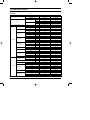
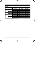
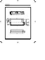
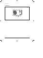
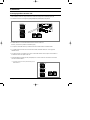
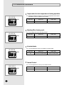
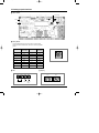
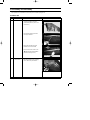
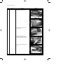
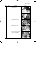
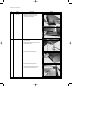
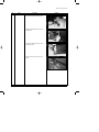
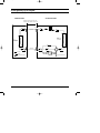
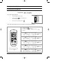
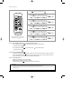
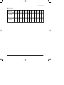
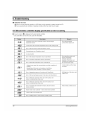
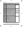
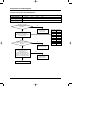
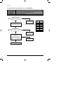
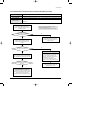
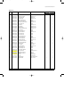
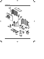
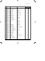
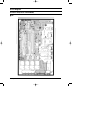
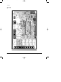
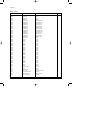
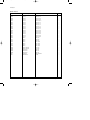
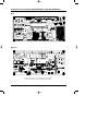
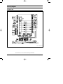
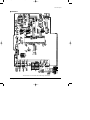
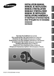
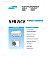
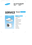
DB98_16009A(1)_CO
12/17/03 4:29 PM
Page 3
DUCT TYPE AIR CONDITIONER
INDOOR UNIT
OUTDOOR UNIT
DH052EAM
DH070EAM
UH052EAMT
UH070EAMT
SERVICE
AIR CONDITIONER
Manual
CONTENTS
11. Product Specifications
12. Installation
13. Disassembly and Reassembly
14. Refrigerating Cycle Diagram
15. Set Up the Model Option
16. Troubleshooting
17. Exploded Views and Parts List
18. PCB Diagram
19. Wiring Diagram
10. Schematic Diagram
DB98_16009A(1)_1
12/17/03 4:21 PM
Page 1
1. Product Specifications
1-1 Table
MODEL
INDOOR UNIT
DH052EAM
DH070EAM
OUTDOOR UNIT
UH052EAMT
UH070EAMT
BTU/hr
18,700
23,900
Watts
5,500
7,000
BTU/hr
20,400
26,300
Cooling
Capacity
Heating
Watts
Power Supply
Power Input
Running Current
Fan Speed
Air Circulation
Indoor Unit
Noise Level
(Sound Pressure)
Heat Exchanger
Fan
Dimension
Weight
Fan Speed
Watts
1,800
2,450
Heating
Watts
1,900
2,650
Cooling
A
8.0
11.0
Heating
A
8.4
11.9
U-High
r.p.m
800
940
High
r.p.m
730
810
Mid
r.p.m
680
760
Low
r.p.m
630
710
U-High
m /min
20
23
High
m3/min
18
21
Mid
m3/min
17
20
3
Low
m /min
16
19
High
dB(A)
45
46
Mid
dB(A)
44
45
Low
dB(A)
43
44
Type
Slit-fin coil
Slit-fin coil
Row x Stages x Fin Pitch
2 x 12 x 1.5(1,100mm)
2 x 12 x 1.5(1,100mm)
Type
Sirocco
Sirocco
97
97
3
Motor Output
W
H
mm
260
260
W
mm
1,340
1,340
D
mm
600
600
Net / Gross
kg
41 / 47
41 / 47
High
r.p.m
750
850
r.p.m
400
340
dB(A)
61
61
Propeller Fan
Propeller Fan
Low
Type
Motor Output
W
Type
Outdoor Unit
Compressor
Model
Motor Output
kW
Protection
Heat Exchanger
60
73
Rotary
Rotary
NN21VBAMT
NN29VACMT
1.3
1.9
Internal
Internal
Type
Slit-fin coil
Slit-fin coil
Row x Stages x Fin Pitch
2 x 28 x 1.5
2 x 28 x 1.5
Control
EEV
EEV
Type
R410A
R410A
1,550
1,650
Refrigerant
Charge
Samsung Electronics
7,700
1ø, 220~240V~, 50Hz
Cooling
Sound Pressure Level
Fan
6,000
1ø, 220~240V~, 50Hz
g
1
DB98_16009A(1)_1
12/17/03 4:21 PM
Page 2
Table(cont.)
INDOOR UNIT
MODEL
Outdoor Unit
Dimension
Weight
Indoor Unit
Condition
Outdoor Unit
Pipe O.D. Size
Piping
OUTDOOR UNIT
DH070EAM
UH052EAMT
UH070EAMT
H
mm
648
648
W
mm
880
880
D
mm
310
310
Net / Gross
kg
67 / 72
69 / 74
Cool(DB/WB)
˚C
27 / 19
27 / 19
Heat(DB/WB)
˚C
20 / 15
20 / 15
Cool(DB/WB)
˚C
35 / 24
35 / 24
Heat(DB/WB)
˚C
7/6
7/6
Liquid
mm(inch)
6.35(1/4")
6.35(1/4")
Gas
mm(inch)
12.7(1/2")
15.88(5/8")
Flare
Flare
Height
m
Max. 15
Max. 15
Pipe Length
m
Max. 30
Max. 30
Connection Method
Between
DH052EAM
Notice : This model is tested under the external static pressure of 4mmAq.
Notice : Air Flow rate : Fan Step Control : Low → Mid → High → Ultra High
2
Samsung Electronics
DB98_16009A(1)_1
12/17/03 4:21 PM
Page 3
1-2 Dimensions
1-2-1 Indoor Unit
(Unit : mm)
Samsung Electronics
3
DB98_16009A(1)_1
12/17/03 4:21 PM
Page 4
Product Specifications
1-2-2 Outdoor Unit
4
31
660
880
0
648
(Unit : mm)
Samsung Electronics
DB98_16009A(1)_1
12/17/03 4:21 PM
Page 5
2. Installation
2-1 Assigning Address to Indoor Unit
1. Before installing the indoor unit, assign an address to the indoor unit according to the air conditioning system plan.
2. The address of the indoor unit is assigned by adjusting MAIN(SW02) and RMC(SW01) rotary switches.
K1 K2 K3 K4
SW03
K5 K6 K7 K8
SW04
K9 K10 K11 K12
SW05
SW02 MAIN
SW01 RMC
3. The MAIN address is for communication between the indoor unit and the outdoor unit.
Therefore, you must set it to operate the air conditioner properly.
4. It is required to set the RMC address if you install the wired remote controller and/or the centralized controller.
5. If you install optional accessories such as the wired remote controller, centralized controller, etc. see an appropriate
installation manual.
6. If an optional accessory is not installed, you do not have to set the RMC address. However, adjust K1 and K2 switches of
the SW03 DIP switch to "ON" position in this case.
7. Set the MAIN address by adjusting the rotary switch(SW02) from 0 to F. Each indoor unit connected to the same outdoor
unit must have different address.
7. i. e. If an indoor unit does not have an optional accessory and its
MAIN address is "4".
K1 K2 K3 K4
SW03
K5 K6 K7 K8
SW04
K9 K10 K11 K12
SW05
SW02 MAIN
Samsung Electronics
SW01 RMC
5
2-2 Additional functions
Compensation for lost temperature in heating operation
◆ Reduces the difference between an actual room temperature and a sensed
temperature by the air conditioner when heating.
K5 K6 K7 K8
SW04
Switch No.
Switch ON
Switch OFF
K5
2°C compensation
5°C compensation
Adjusting filter cleaning cycle
◆ You can adjust the cycle for filter sign indicator.
K5 K6 K7 K8
SW04
Switch No.
Switch ON
Switch OFF
K6
1000 hours
2000 hours
Hot water heater
◆ You must adjust the K7 when you install the hot water heater.
K5 K6 K7 K8
SW04
Switch No.
Switch ON
Switch OFF
K7
No use of hot water heater
Use of hot water heater
External Control
◆ You must adjust the K11 when you use external control.
K9 K10 K11 K12
SW05
6
Switch No.
Switch ON
Switch OFF
K11
No use of external control
Use of external control
DB98_16009A(1)_1
12/17/03 4:21 PM
Page 7
2-3 Setting Up Option Switches
■ Option Switch
Rotary Switch
Display
Key
■ Rotary Switch
■ You should display that how many indoor units are connected to the
outdoor unit. Refer to the table below, then turn the arrow to appropriate
position.
Switch No.
Number of
indoor unit(s)
Switch No.
Number of
indoor unit(s)
0 or 1
One
9
Nine
2
Two
A
Ten
3
Three
B
Eleven
4
Four
C
Twelve
5
Five
D
Thirteen
6
Six
E
Fourteen
7
Seven
F
Fifteen
8
Eight
-
-
■ KEY
■ Display
DIS 1
K1
K2
CHECK MODE
Samsung Electronics
K3
RESET
DIS 2
K4
DISPLAY
MODE
SEG 1
SEG 2
SEG 3
SEG 4
7
DB98_16009A(1)_1
12/17/03 4:21 PM
Page 8
Installation
■ Summary of KEY functions
Function
K1
Number
(Displayed
on SEG 3, 4)
of press times
K2
(Displayed on SEG 3, 4)
K3
(Displayed on SEG 3, 4)
K4
(Displayed on SEG 3, 4)
1
Adding refrigerant at
heating mode
Adding refrigerant at
cooling mode
Reset
Displays data
2
Test operation at
heating mode
Test operation at
cooling mode
-
-
3
End
Pump Down for recovery
of refrigerant
-
-
4
-
End
-
-
✳ Use the K1 only for heat pump models.
■ Reading data indicated on the display
KEY
K1
Example
Number of
press
Item
Display
1
Adding refrigerant for heat pump models
2
Test operation for heat pump models
3
End
1
Adding refrigerant for cooling only models
2
Test operation for cooling only models
3
Pump Down for recovery of refrigerant
4
End
Meaning
K2
K3
K4
8
Reset
110 °C
1
Discharge temperature of compressor
2
Temperature of outdoor heat exchanger
38 °C
3
Outdoor temperature
34 °C
4
Step of electronic expansion valve
(0 step : all closed, 480 step : all open)
5
Temperature of evaporator
6
Indoor temperature
7
Stopping view mode & display communication data
120STEP
(12 x 10)
-2 °C
12 °C
22 °C
Samsung Electronics
DB98_16009A(1)_1
12/17/03 4:21 PM
Page 9
3. Disassembly and Reassembly
Stop operation of the air conditioner and remove the power cord before repairing the unit.
3-1 Indoor Unit
No
Parts
1
Filter-Pre
Procedure
Remark
1) Disassemble 2 screws of indication part
and then assemble the direction of
2 Plate-Handle places by use of screw
as shown in 2).
2) Turn the Plate Handle by hand when
removing the Filter-Pre.
3) When pulling the Filter-Pre handle,
the Filter-Pre can be assembled.
✳ Be sure to remove the cushion on the
marked part after initial installation.
(It cause the damage of noise).
2
Blower & Duct
Samsung Electronics
1) After disassembling 9 places indicating
screws, detach Ass'y Cover Bottom.
9
DB98_16009A(1)_1
12/17/03 4:21 PM
Page 10
Disassembly and Reassembly
No
Parts
Procedure
Remark
2) Disassemble 6 indicating screws.
3) Detach the Sensor Holder from the
Ass'y Fan Case.
4) Detach from Ass'y Control In the
capacitor connection wire between the
Motor-Fan in and housing Connector.
5) Detach the Ass'y Blower and Duct from
the set.
10
Samsung Electronics
DB98_16009A(1)_1
12/17/03 4:21 PM
Page 11
Disassembly and Reassembly
No
Parts
3
Control In
Procedure
Remark
1) After disassembling 1 indicating screw,
detach the Cover-Control.
2) Detach the Motor-Fan in and Sensor
Connector connected to PCB.
3) Disassemble 2 indicating screws.
(arrow mark)
4) Hold the Ass'y Control In by hand to lift up
a little and then release the status of
hanging on the hanging slot.
Samsung Electronics
11
DB98_16009A(1)_1
12/17/03 4:21 PM
Page 12
Disassembly and Reassembly
No
Parts
4
Drain Pan
5
EVAP
Procedure
Remark
1) Disassemble 4 indicating screws to
detach Ass'y Drain Pan. (2 screws
each at left and right side)
✳ Work is possible when disassembling the
Ass'y Drain Pan.
1) Disassemble 8 indicating screws. (4 each
at left and right side)
2) Disassemble 6 indicating screws.
3) Disassemble 5 indicating screws.
✳ It is possible at the status of No.3 Ass'y
Control In disassembly at the time.
12
Samsung Electronics
DB98_16009A(1)_1
12/17/03 4:21 PM
Page 13
Disassembly and Reassembly
No
Parts
Procedure
Remark
4) After disassembling 4 indicating screws.
5) Pull the Cabinet-Side LF, RH by hand to
disassemble.
6) Separate 4 indicating screws. (2 each at
left and right side)
7) Detach it from the set if the Ass'y-Evap
pull up.
Samsung Electronics
13
DB98_16009A(1)_1
12/17/03 4:21 PM
Page 14
Disassembly and Reassembly
No
Parts
6
Holder Outlet
Procedure
Remark
✳ When connecting canvas to the discharge
side.
1) Disassemble 4 indicating screws.
(2 each at left and right side)
2) Disassemble 12 indicating screws.
(6 each at upper and lower side)
✳ After connecting canvas to the
disassembled Ass'y Holder Outlet 2),
attach the Ass'y Holder Outlet to the
set in the reverse order.
14
Samsung Electronics
DB98_16009A(1)_1
12/17/03 4:21 PM
Page 15
3-2 Outdoor Unit
No
Parts
1
Cabinet
Procedure
Remark
1) Turn off the unit and remove the power
cable.
2) Detach the top Cover.
3) Detach the Control Box Cover.
4) Unplug the Ass'y Cable.
5) Detach the Cabinet-Side.
6) Detach the Cabinet-Front.
✳ When you assemble the parts, check if
the each parts and Component Electric
Box are fixed firmly.
2
Fan Motor
&
Propeller Fan
Samsung Electronics
1) Detach the Nut Flange.
(Turn to the clockwise)
2) Disassemble the Propeller Fan.
15
DB98_16009A(1)_1
12/17/03 4:21 PM
Page 16
4. Refrigerating Cycle Diagram
INDOOR UNIT
OUTDOOR UNIT
*Allowable pipe length : Max. 50m
*Allowable drop distance : Max. 30m
EEV
3-Way Valve
Liquid Side
Filter
Filter
Heat
Exchanger
(Condensor)
Heat
Exchanger
(Evaporator)
Gas Side
3-Way Valve
Cooling
Heating
Gas leak check point
16
Muffler
Accumulator
Compressor
High pressure switch
Samsung Electronics
DB98_16009A(1)_1
12/17/03 4:21 PM
Page 17
5. Set Up the Model Option
5-1 Setting Option Setup Method
ex) Option No. :
Step 1 : Enter the Option Setup mode.
1st
Take out the batteries of remote control.
2nd
Press the temperature
insert the battery again.
3rd
Make sure the remocon display shown as
button simultaneously and
.
Step 2 : Enter the Option Setup mode and select your option according to the following procedure.
1
The default value is
Otherwise, push the
.
button to
.
Every time you push the button, the display panel reads
or
repeatedly.
1
2
Push the
2
3
4
button to set the display panel to
.
Every time you push the button, the display panel reads
...
repeatedly.
3
Push the
button to set the display panel to
.
Every time you push the button, the display panel reads
...
repeatedly.
5
6
4
Push the
button to set the display panel to
.
Every time you push the button, the display panel reads
...
repeatedly.
5
Push the
button to set the display panel to
.
Every time you push the button, the display panel reads
...
repeatedly.
✳ Setting is not required if you must
a value which has a
default.
Samsung Electronics
6
Push the
button to set the display panel to
.
Every time you push the button, the display panel reads
...
repeatedly.
17
DB98_16009A(1)_1
12/17/03 4:22 PM
Page 18
Set Up the Model Option
7
Press
button, then the default value is
.
8
Push the
button to set the display panel to
.
Every time you push the button, the display panel reads
...
repeatedly.
7
8
9
9
Push the
button to set the display panel to
.
Every time you push the button, the display panel reads
...
repeatedly.
10
11
10
Push the
12
button to set the display panel to
.
Every time you push the button, the display panel reads
...
repeatedly.
11
Push the
button to set the display panel to
.
Every time you push the button, the display panel reads
...
repeatedly.
12
✳ Setting is not required if you must
a value which has a
default.
Push the
button to set the display panel to
.
Every time you push the button, the display panel reads
...
repeatedly.
Step 3 : Upon completion of the selection, check you made right selections.
Press the Mode Selection key,
to set the display part to and check the display part.
The display part shows
.
Press the Mode Selection key,
The display part shows
to set the display part to
and check the display part.
.
Step 4 : Pressing the ON/OFF button (
)
When pressing the operation ON/OFF key with the direction of remote controller for unit, the sound ''Ding'' or ''Diriring'' is
heard and the OPERATION ICON( ) lamp of the display is flickering at the same time, then the input of option is completed. (If the diriring sound isn't heard, try again pressing the ON/OFF button.)
Step 5 : Unit operation test-run
First, Remove the battery from the remote controller.
Second, Re-insert the battery into the remote controller.
Third, Press ON/OFF button( ) with the direction of remote controller for set.
• Error Mode
1st If all lamps of indoor unit are flickering, Plug out and plug in again and pressing ON/OFF key to retry.
2nd If the unit is not working properly or all lamps are continuously flickering after setting the option code, see if the correct option code is
set up for it's model.
18
Samsung Electronics
DB98_16009A(1)_1
12/17/03 4:22 PM
Page 19
Set Up the Model Option
■ OPTION ITEMS
REMOCON
SEG1
SEG2
SEG3
SEG4
SEG5
SEG6
SEG7
SEG8
SEG9 SEG10 SEG11 SEG12
DH052EAM
0
1
5
4
4
4
1
A
0
0
0
0
DH070EAM
0
1
5
4
4
2
1
c
0
0
0
0
MODEL
Samsung Electronics
19
DB98_16009A(1)_1
12/17/03 4:22 PM
Page 21
6-2 LED Display on the receiver & display unit
■ LED Display
Indicators
Concealed Type
Abnormal conditions
Operating
Blue
Red
Standard Type
Power reset
Error of temperature sensor in indoor unit
(OPEN/SHORT)
Displayed on appropriate indoor unit
which is operating
Error of heat exchanger sensor in indoor
unit(OPEN/SHORT)
Displayed on appropriate indoor unit
which is operating
Error of outdoor temperature sensor
Error of COND sensor
Error of DISCHARGE sensor
(OPEN/SHORT)
Displayed on appropriate indoor unit
which is operating
Displayed on outdoor unit
1. No communication for 2 minutes between
indoor unit and outdoor unit
(communication error for more than
2 minutes)
1. Error of indoor unit: Displayed on
the indoor unit regardless of
operation
2. Indoor unit receiving the communication
error from outdoor unit
2. Error of outdoor unit: Displayed on
the indoor unit which is operating
3. Outdoor unit tracking 3 minute error
4. When sending the communication error from
outdoor unit the mismatching of the
communication numbers and installed
numbers after completion of tracking. (communication error for more than 2 minutes)
1. Communication error between indoors
(Communication error for more than
2 minutes)
Error of indoor unit: Displayed on the
indoor unit regardless of operation
2. Slave of indoor unit tracking error
1. 2nd detection of high temperature COND
2. 2nd detection of high temperature
DISCHARGE
Displayed on appropriate indoor
unit which is operating
Displayed on outdoor unit
3. Error of reverse phase
Error of float switch
Error of setting option switches for optional
accessories
EEPROM error
EEPROM option error
- If you turn off the air conditioner when the LED is flickering, the LED is also turned off.
- If you re-operate the air conditioner, it operates normally at first, then detect an error again.
Samsung Electronics
: On
: Flickering
: Off
21
DB98_16009A(1)_1
12/17/03 4:22 PM
Page 22
6-3 Outdoor Unit
If an error occurs during the operation, it is displayed on the outdoor unit PCB.
Display
Explanation
High temperature of Discharge (Protection control)
Remark
Error about protection
control of outdoor unit
High temperature of outdoor heat exchanger (Protection control)
COMP DOWN to protect being frozen
Error of momentary power failure (disappears when the unit is Off/On)
Error of OUT TEMP sensor (OPEN/SHORT)
Error of temperature sensor in outdoor heat exchanger (OPEN/SHORT)
Error of Discharge TEMP sensor (OPEN/SHORT)
System Down caused by communication error after completion of tracking
Errors about outdoor unit
sensor (OPEN/SHORT)
Detection during the
operation of indoor unit
(Sensing and sending errors
into the communication data)
Communication and
indoor unit errors
Mismatching of the indoor unit numbers set with those
communicated after completion of tracking
Error of float switch in indoor unit
Error of setting option switches for optional accessories
x
OPEN/SHORT error of room sensor in indoor unit
x
OPEN/SHORT error of eva in sensor in indoor unit
x
EEPROM option error
x
Error of fan starting
Self-diagnosis of indoor and
outdoor unit (x:indoor unit
address)
Displays of operating status
Open error of electronic expansion valve in outdoor unit
(Detected once or more times)
Close error of electronic expansion valve in outdoor unit
(Detected once or more times)
Flicker
Below -5°C when cooling (Outdoor temperature)
Flicker
Over 30°C when heating (Outdoor temperature)
K1, K2, K3, K4,
K5 Flicker
The order of priority : E1 → E2 → E4 → E5 → P0 → P1 → P5 → P6 → t1 → t2 → t3 → tu → to → G4 → G5 → E3 → qx → rx → vx →
K1, K2, K3, K4, K5
The order of priority : - In case that the same error displays from multi-indoor units, the one having the faster address has the priority.
22
Samsung Electronics
DB98_16009A(1)_1
12/17/03 4:22 PM
Page 23
6-4 Sequence for trouble diagnosis
6-4-1 Outdoor temperature sensor(OPEN/SHORT)
Outdoor unit display
Er → t1 (Outdoor temperature sensor OPEN/SHORT error)
(Operation)
Indoor unit display
How to determine
Reason of error
(Timer)
(Airflow)
(Filter)
Disconnection and short of outdoor temperature sensor
Disconnection or leak of applied sensor
Is not separated the out
temperature sensor connector from
PCB?(CN41)
No
Reoperation
after connection to
connector PCB
Yes
To measure the resistance value
between two terminals after
separating the out temperature sensor
connector from PCB
Yes
At this time, Is not largely
deviate the resistance value from side
table value?
No
Resistance
(kΩ)
70
2.2
60
3.0
50
4.2
40
5.8
30
8.3
20
12.1
10
18.0
0
27.3
-10
43.0
Outdoor unit thermistor
self badness (exchange)
Yes
To check the out temperature
sensor is normal or not by use of
out data display part
➞ To check the temperature data is
normal or not after pressing K4 3 times.
At this time, is occurred the difference
between the out temperature and data?
Temperature
(˚C)
No
PCB and sensor are normal.
To perform the test
operation by use of K2
Yes
Reoperation after PCB exchange
Samsung Electronics
23
DB98_16009A(1)_1
12/17/03 4:22 PM
Page 24
Troubleshooting
6-4-2 Outdoor heat exchanger temperature sensor error(OPEN/SHORT)
Outdoor unit display
Er → t2 (Outdoor heat exchanger temperature sensor error(OPEN/SHORT)
(Operation)
Indoor unit display
How to determine
Reason of error
(Timer)
(Airflow)
(Filter)
Disconnection and short of outdoor heat exchanger temperature sensor
Disconnection or leak of Applied sensor
Is not separated the out
heat exchanger temperature sensor
connector from PCB?(CN41)
No
Reoperation
after connection to
connector PCB
Yes
To measure the resistance value
between two terminals after separating
the out heat exchanger temperature
sensor connector from PCB
Yes
At this time, Is not largely
deviate the resistance value from side
table value?
No
Resistance
(kΩ)
70
2.2
60
3.0
50
4.2
40
5.8
30
8.3
20
12.1
10
18.0
0
27.3
-10
43.0
Outdoor heat exchanger
temperature self badness
(exchange)
Yes
To check the out temperature
sensor is normal or not by use of
out data display part
➞ To check the temperature data is
normal or not after pressing K4 2 times.
At this time, is occurred the difference
between the out temperature and data?
Temperature
(˚C)
No
PCB and sensor are
normal.
Yes
Reoperation after PCB exchange
24
Samsung Electronics
DB98_16009A(1)_1
12/17/03 4:22 PM
Page 25
Troubleshooting
6-4-3 Outdoor discharge temperature sensor error(OPEN/SHORT)
Outdoor unit display
Er → t3 (Outdoor discharge temperature sensor OPEN/SHORT error)
(Operation)
Indoor unit display
How to determine
Reason of error
(Timer)
(Airflow)
(Filter)
Disconnection and short of outdoor heat exchanger temperature sensor
Disconnection or leak of Applied sensor
Is not separated the outdoor
discharge temperature sensor connector
from PCB?(CN42)
No
Reoperation
after connection to
connector PCB
Yes
To measure the resistance value
between two terminals after separating
the outdoor discharge temperature
sensor connector from PCB
Yes
At this time, Is not largely
deviate the resistance value from
side table value?
No
Outdoor heat exchanger
temperature self badness
(exchange)
Yes
To check the out temperature
sensor is normal or not by use of out
data display part
➞ To check the temperature data is
normal or not after pressing K4 1 times.
At this time, is occurred the difference
between the out temperature and data?
Yes
Temperature
(˚C)
Resistance
(kΩ)
130
8.9
120
11.2
100
18.5
80
32
60
59
25
200
20
242
10
362
0
553
-10
No
PCB and sensor are normal.
To perform the test
operation by use of K2
Reoperation after PCB exchange
Samsung Electronics
25
DB98_16009A(1)_1
12/17/03 4:22 PM
Page 26
Troubleshooting
6-4-4 Communication error during the operation
Outdoor unit display
Er → E1 (Communication error during the operation)
(Operation)
Indoor unit display
Disconnection
and short of
communication lines
Reason of error
(Timer)
(Airflow)
(Filter)
Disconnection and short of outdoor heat exchanger temperature sensor
Disconnection or leak of Applied sensor
To check the display after
pressing the reset key on outdoor PCB
Multi type
After 2 minutes, to check if PCB address
setting of indoor unit displayed th
communication error among indoor units is
overlapped or not.
(If the indoor unit address is overlapped, the
communication error is occurred.)
- In this case, the communication error is
occurred to over two indoor units set
wrong.
No
When tracking, is there any
indoor answer from display part?
Yes
To measure the 2 lines of outdoor side
by scope after removing the
communication line connecting from
outdoor unit to indoor unit.
If address is no fault,
to exchange the indoor unit PCB after
communication line check.
At this time, is the voltage
between lines spherical wave over DC ±0.7V
like below figure?
No
Yes
To exchange PCB after checking
the outdoor unit communication line
and connector
After connecting again the communication
line connecting from outdoor unit to indoor unit,
to remove the communication
connector on indoor unit PCB, and find the
indoor unit preventing communication
through connecting the communication
connectors each by each, and then exchange
the indoor unit PCB after line check.
Good
Bad
+0.7V
-0.7V
26
Samsung Electronics
DB98_16009A(1)_1
12/17/03 4:22 PM
Page 27
Troubleshooting
6-4-5 Communication error between indoor and outdoor after initial power input.
Outdoor unit display
Er → E2 (Tracking error)
(Operation)
Indoor unit display
How to determine
Reason of error
(Timer)
(Airflow)
(Filter)
Mismatching the communicating indoor unit and setting switch indoor numbers When outdoor tracking
Communication error between the indoor unit and outdoor unit, and installation number switch
setting miss
To check the setting value of
indoor unit installation number setting
switch of outdoor PCB and actual indoor unit
installation numbers
Is equal indoor unit actual
installation number and installation
number setting switch?
If the indoor unit number installed is one, set the
outdoor unit switch forward to "0", "1"
➞ "0" and "1" spell the connection of an indoor unit.
No
Yes
After setting the indoor unit installation setting
number switch correctly, Re-perform the
tracking by pressing the reset key K3 of
outdoor unit PCB
To press the reset key K3 of outdoor unit
PCB and check the display to check the
number of indoor units answering to the
tracking
When tracking, is there any
indoor answer from display part?
Yes
To measure the 2 lines of outdoor unit side by
use of scope after removing the communication
line connecting from outdoor unit to indoor unit
At this time, is the voltage
between lines spherical wave over
DC ±0.7V ?
Yes
No
Multi type
After 2 minutes, to check if PCB address setting
of indoor unit displayed the communication error
among indoor units is overlapped or not .
(If the indoor unit address is overlapped, the
communication error is occurred.)
- In this case, the communication error is
occurred to over two indoor units set wrong
If address is no fault,
to exchange the indoor unit PCB after
communication line check.
After connecting again the communication line
connecting from outdoor unit to indoor unit,
to check this communication is reverse or not,
and if there is no fault, to find the indoor unit
preventing communication through connecting
indoor units each by each, and then
exchange the indoor unit PCB after line check
Samsung Electronics
27
DB98_16009A(1)_1
12/17/03 4:22 PM
Page 28
Troubleshooting
6-4-6 Indoor floating switching error
Outdoor unit display
Er → E3 (Indoor floating switching error )
(Operation)
Indoor unit display
How to determine
Reason of error
(Timer)
(Airflow)
(Filter)
The status continues over 1 minute that indoor unit floating switch is opened.
The rising of water level of drain pan due to the disorder of indoor unit drain pump,
the badness of detection sensor
Is the indoor unit
error occurred cassette type?
No
Refer to the drain pump
option in the next page.
Yes
Is the resistance value ∞
when measuring the resistance value
of two terminal after taking out the floating
switch connector connected to indoor
unit PCB? (Open status)
No
To re-assembly the floating switch
connector and perform the reset of
outdoor power(Required the reset of
indoor unit power)
Yes
Is the same error occurred?
Is much the water of drain pan ?
Yes
No
Yes
To exchange the indoor unit PCB
No
Normal operation
To reset the indoor unit power
and check the drain pump operation
To determine the floating switch
bad To reset the indoor unit
power after exchange
No
Is operated the drain pump?
Yes
Is lowing the water level?
No
Is the terminal voltage
of drain pump PCB about
AC 220V?
No
Yes
Yes
To exchange the drain pump
To exchange the indoor unit PCB
Normal operation
To exchange the drain pump
28
❋ Note : E3 error should be released when
indoor unit power is reset.
Samsung Electronics
DB98_16009A(1)_1
12/17/03 4:22 PM
Page 29
MEMO
Samsung Electronics
29
DB98_16009A(1)_1
12/17/03 4:22 PM
Page 30
7. Exploded Views and Parts List
7-1 Indoor Unit
1
2
19
5
19-2
13
19-3
18
19-6
5-5
19-1
5-3
19-4
5-6
19-5
5-4
5-7
12
5-1
17
5-2
10
9
4
11
8
14
15
7
16
3
6
You can search for the updated part code
number through the ITSELF.
URL : http://itself.sec.samsung.co.kr
30
Samsung Electronics
DB98_16009A(1)_1
12/17/03 4:22 PM
Page 31
Exploded Views and Parts List
■
Parts List
No.
Code No.
Description
Q'TY
Specification
DH052EAM
DH070EAM
1
DB63-00076A
COVER-TOP
SGCC-M T0.8
1
1
2
DB63-00074A
COVER-CASE DUCT
SGCC-M T0.8
1
1
3
DB94-00022A
ASS'Y-DRAIN PAN
ASS'Y, BLK
1
1
4
DB61-00099A
CASE-BOTTOM
SGCC-M, T0.8
1
1
5
DB94-00023C
ASS'Y-BLOWER DUCT
ASS'Y
1
1
5-1
DB64-00071A
PANEL-DUCT HOLDER
SGCC-M, T1.2
1
1
5-2
DB61-00155A
BRACKET-MOUNT MOTOR
SGCC-M, T2.0
1
1
5-3
DB90-00121A
ASS'Y-CASE FAN
ASS'Y
2
2
5-4
DB67-00046A
BLOWER-LF
SGCC-M, ø175
1
1
5-5
DB67-00046B
BLOWER-RH
SGCC-M, ø175
1
1
5-6
DB31-00025A
MOTOR-FAN IN
OSME-1004 SAC
1
1
5-7
DB61-00499A
BRACKET-MOTOR GUIDE
SGCC-M, T1.6
1
1
6
DB90-00117A
ASS'Y-CABI LF
ASS'Y
1
1
7
DB90-00119C
ASS'Y-CABI INLET LF
ASS'Y
1
1
8
DB70-00026B
PLATE-HANGER LF
SGCC-M, T2.0
1
1
9
DB96-03225A
ASS'Y-EVAP UNIT
ASS'Y
1
-
DB96-03225B
ASS'Y-EVAP UNIT
ASS'Y
-
1
10
DB90-00120C
ASS'Y-CABI INLET RH
ASS'Y
1
1
11
DB90-00118A
ASS'Y-CABI SIDE RH
ASS'Y
1
1
12
DB70-00027B
PLATE-HANGER RH
SGCC-M, T2.0
1
1
13
DB64-00121A
CABINET-SIDE RH B
SGCC-M, T0.8
1
1
14
DB90-00393A
ASS'Y-HOLDER OUTLET
ASS'Y
1
1
15
DB90-00114A
ASS'Y-COVER BOTTOM
ASS'Y
1
1
16
DB71-00019A
PLATE-HANDLE
SGCC-M, T1.2
2
2
17
DB74-00006A
FILTER-PRE
PE, 36x40
1
1
18
DB63-00080A
COVER-CONTROL
SGCC-M, T0.8
1
1
19
DB93-01616F
ASS'Y-CONTROL IN
ASS'Y
1
-
DB93-01616G
ASS'Y-CONTROL IN
ASS'Y
-
1
19-1
DB90-00116A
ASS'Y-CASE CONTROL
ASS'Y
1
1
19-2
DB93-00849R
ASS'Y-PCB MAIN
DPM24K DUCT IN
1
1
19-3
DB65-00004H
TERMINAL-BLOCK 6P
DAF-6P
1
1
DB65-00169A
TERMINAL-BLOCK 6P
DAF-6P
1
1
2301-001370
C-FILM
2.5µF/450VAC
1
-
2301-001378
C-FILM
3.5µF/450VAC
-
1
19-5
DB26-10065B
TRANS-POWER
DC17 AC230V 50Hz
1
1
19-6
DB61-40291B
HOLDER-WIRE
PP, T2.0, BLK
2
2
19-4
Samsung Electronics
31
DB98_16009A(1)_1
12/17/03 4:22 PM
Page 32
7-2 Outdoor Unit
20
1
2
21
22
15
23
16
5
4
24
8
13
25
9-7
9-1
9-3
10
3
11
9-6
9
9-2
9-5
14
12
9-4
17
19
26
18
6
7
32
Samsung Electronics
DB98_16009A(1)_1
12/17/03 4:22 PM
Page 33
Exploded Views and Parts List
■
Parts List
No.
Code No.
Description
Q'TY
Specification
UH052EAMT UH070EAMT
1
DB90-01363A
ASS'Y-COVER TOP
ASS'Y
1
1
2
DB90-01388A
ASS'Y CABINET-FRONT
ASS'Y
1
1
3
DB67-00140A
FAN-PROPELLER
AS+GF20%,OD460,3BLADE
1
1
1
4
DB61-01167A
BRACKET-MOTOR
SGCC-M,T1.6
1
5
DB90-00940B
ASS'Y-PARTITION
ASS'Y
1
1
6
DB95-00455A
ASS'Y COMP
SIAM,NN29VACMT
-
1
DB95-00454A
ASS'Y COMP
SIAM,NN21VBAMT
1
-
DB95-30013T
ASS'Y HEATER COMP
40W
1
1
7
8
DB31-00216A
MOTOR-FAN
OSEM-886SRC(S509)
-
1
DB31-00027G
MOTOR-FAN
OSEM-906SRC(S507)
1
-
DB93-02410A
ASS'Y CONTROL OUT
ASS'Y
-
1
DB93-02410B
ASS'Y CONTROL OUT
ASS'Y
1
-
9-1
DB26-10070A
TRANS-POWER
AC230V,DC17V
1
1
9-2
DB65-00112A
TERMINAL BLOCK-6P
35A 4P,25A 2P
1
1
9-3
3501-001204
RELAY POWER
MUF20CF,2A
1
1
9-4
DB61-30625A
BRACKET-TERMINAL
SGCC-M
1
1
9-5
DB93-40264E
ASS'Y CONTROL BOX OUT
ASS'Y
1
1
9-6
DB61-00152A
CASE-PCB-OUT
T2.5,ABS,BLK
1
1
9-7
2301-001369
C-FILM
3uF/450VAC
1
1
10
2501-001236
C-OIL
30uF/450VAC
-
1
2501-001235
C-OIL
25uF/450VAC
-
1
2501-001240
C-OIL
50uF/450VAC
1
-
9
11
DB32-00021F
THERMISTOR
AWG22,L470,L550
1
1
12
DB32-00071C
THERMISTOR
AWG22,L600
1
1
13
DB61-01685A
BRACKET-CAPACITOR
SGCC-M
-
1
DB69-60008A
BAND-CAPACITOR
SGCC-M
1
-
14
DB93-00185K
ASS'Y PCB MAIN
CEILING OUTDOOR PCB
1
-
DB93-00185J
ASS'Y PCB MAIN
CEILING OUTDOOR PCB
-
1
15
DB90-40176D
ASS'Y COVER CONTROL
ASS'Y
1
1
16
DB90-01189B
ASS'Y-ASS'Y CABI SIDE RH
ASS'Y
1
1
17
DB62-01471A
INSULATION-CLOTH COMP
UH070EAMT
-
1
DB62-02295A
INSULATION-CLOTH COMP
UH052EAMT
1
-
18
19
DB96-02876A
ASS'Y 4WAY VALVE
ASS'Y
-
1
DB96-02877A
ASS'Y 4WAY VALVE
ASS'Y
1
-
DB96-02896A
ASS'Y EEV VALVE
ASS'Y
-
1
DB96-02896B
ASS'Y EEV VALVE
ASS'Y
1
-
20
DB63-00613A
GUARD-COND
SECC-P,T1.6
1
1
21
DB61-01221A
GUIDE-SCREEN
P.E.H 100%,T2.5,1015x615,BLK
1
1
22
DB63-00320A
GUARD-FAN
HSWR,460
1
1
23
DB96-02849A
ASS'Y COND UNIT
UH070EAMT,UH052EAMT
1
1
24
DB96-02936A
ASS'Y COLLECTOR IN
ASS'Y
1
1
25
DB96-02937A
ASS'Y COLLECTOR OUT
ASS'Y
1
1
26
DB90-01291A
ASS'Y CABINET BASE OUT
ASS'Y
1
1
Samsung Electronics
33
DB98_16009A(1)_1
12/17/03 4:22 PM
Page 34
MEMO
34
Samsung Electronics
DB98_16009A(1)_1
12/17/03 4:22 PM
Page 35
8. PCB Diagram
8-1 Indoor Unit(Code No : DB93-00849N)
■ TOP
Samsung Electronics
35
DB98_16009A(1)_1
12/17/03 4:22 PM
Page 36
PCB Diagram
■ BOTTOM
36
Samsung Electronics
DB98_16009A(1)_1
12/17/03 4:22 PM
Page 37
PCB Diagram
■
Parts List
Location No.
Description
Specification
Q'TY
BD71
DIODE BRIDGE
DF06S
1
C101
C-ELEC
2200uF 35V
1
C102
C-CHIP
CS2012Y 5V 104Z5
1
C103
C-ELEC
2200uF 25V
1
C104
C-CHIP
CS2012Y 5V 104Z5
1
C105
C-ELEC
SD 470uF,25V
1
C201
C-CHIP
CS2012Y 5V 104Z5
1
C202
C-CHIP
CS2012Y 5V 104Z5
1
C203
C-CHIP
CS2012Y 5V 104Z5
1
C204
C-CHIP
CS2012 5V 103Z5
1
C205
C-CHIP
CS2012 5V 103Z5
1
C301
C-CHIP
CS2012 5V 103Z5
1
C302
C-CHIP
CS2012Y 5V 104Z5
1
C303
C-CHIP
CS2012Y 5V 104Z5
1
C304
C-CHIP
CS2012Y 5V 104Z5
1
C305
C-CHIP
CS2012Y 5V 104Z5
1
C306
C-CHIP
CS2012Y 5V 104Z5
1
C311
C-CHIP
CS2012 5V 103Z5
1
C312
C-CHIP
CS2012Y 5V 104Z5
1
C313
C-CHIP
CS2012Y 5V 104Z5
1
C314
C-CHIP
CS2012Y 5V 104Z5
1
C315
C-CHIP
CS2012Y 5V 104Z5
1
C316
C-CHIP
CS2012Y 5V 104Z5
1
C401
C-CHIP
CS2012Y 5V 104Z5
1
C402
C-CHIP
CS2012Y 5V 104Z5
1
C403
C-CHIP
CS2012Y 5V 104Z5
1
C413
C-CHIP
CS2012Y 5V 104Z5
1
C501
C-CHIP
CS2012Y 5V 104Z5
1
C502
C-CHIP
CS2012Y 5V 104Z5
1
C503
C-CHIP
CS2012Y 5V 104Z5
1
C504
C-CHIP
CS2012Y 5V 104Z5
1
C505
C-CHIP
CS2012Y 5V 104Z5
1
C506
C-CHIP
CS2012Y 5V 104Z5
1
C508
C-CHIP
CS2012Y 5V 104Z5
1
C509
C-CHIP
CS2012Y 5V 104Z5
1
C510
C-CHIP
CS2012Y 5V 104Z5
1
C511
C-CHIP
CS2012Y 5V 104Z5
1
C901
C-CHIP
CS2012X 7R 102K5
1
C902
C-CHIP
CS2012Y 5V 104Z5
1
C910
C-FILM
2A 472J
1
C911
C-CHIP
CS2012 5V 103Z5
1
C912
C-CHIP
CS2012 5V 103Z5
1
C913
C-CHIP
CS2012 5V 103Z5
1
C914
C-CHIP
CS2012 5V 103Z5
1
C915
C-CHIP
CS2012 5V 103Z5
1
C917
C-CHIP
CS2012Y 5V 104Z5
1
Samsung Electronics
37
DB98_16009A(1)_1
12/17/03 4:22 PM
Page 38
PCB Diagram
■
Parts List(cont.)
Location No.
Description
Specification
Q'TY
CD31
DIODE-TVS
SAC5.0
1
CD32
DIODE-TVS
SAC5.0
1
CD33
DIODE-TVS
SAC5.0
1
CD34
DIODE-TVS
SAC5.0
1
CN11
CONNECTOR
SMW250-03 RED
1
CN31
CONNECTOR
YW396-02V RED
1
CN32
CONNECTOR
YW396-02V WHT
1
CN33
CONNECTOR
YW396-02V BLU
1
CN41
CONNECTOR
SMW250-04 WHT
1
CN51
CONNECTOR
SMW250-02 BLK
1
CN71
CONNECTOR
YW396-03AV BLU
1
CN72
CONNECTOR
YW396-03AV WHT
1
CN73
CONNECTOR
YW396-09AV WHT
1
CN74
CONNECTOR
YW396-03AV YEL
1
CN75
CONNECTOR
YW396-03 BLK
1
CN77
CONNECTOR
YW396-03 RED
1
CN91
CONNECTOR
SMW200-11 WHT
1
D105
DIODE-RECT
IN4007
1
D900
DIODE
4148M
1
D901
DIODE
4148M
1
D902
DIODE
4148M
1
D903
DIODE
4148M
1
D904
DIODE
4148M
1
D905
DIODE
4148M
1
D906
DIODE
4148M
1
D907
DIODE
4148M
1
D908
DIODE
4148M
1
D909
DIODE
4148M
1
D910
DIODE
4148M
1
D911
DIODE
4148M
1
D912
DIODE
4148M
1
D913
DIODE
4148M
1
D914
DIODE
4148M
1
D915
DIODE
4148M
1
D916
DIODE
4148M
1
D917
DIODE
4148M
1
D918
DIODE
4148M
1
D919
DIODE
4148M
1
F701
FUSE
250V,5A
1
F701
HOLDER FUSE
FB58-20
1
F702
FUSE
250V,1A
1
FT71
FILTER NOISE
HP1-P10
1
IC01
HEAT SINK
A6063,L25.5 W15,WHT
1
IC01
IC VOLT REGULATOR
KA7812A
1
IC01
SCREW-TAPPING
PH,M3,L8,FE FZY
1
IC02
IC VOLT REGULATOR
KA7805A
1
38
Samsung Electronics
DB98_16009A(1)_1
12/17/03 4:22 PM
Page 39
PCB Diagram
■
Parts List(cont.)
Location No.
Description
Specification
Q'TY
IC03
IC-RESET
KA7533Z
1
IC04
IC - MCU
MB89635
1
IC05
IC DRIVE
ULN2003AFW
1
IC06
IC DRIVE
ULN2003AFW
1
IC07
IC DRIVE
ULN2003AFW
1
IC18
IC-BUS TRANSCEIVER
MAX485
1
IC19
IC-BUS TRANSCEIVER
MAX485
1
IC51
EEPROM
93LC56B-1/SN
1
LED01
LED LAMP
SY5511 YEL
1
LED02
LED LAMP
SR5511 RED
1
Q201
TR SMALL SIGNAL
2SC2412K
1
Q202
TR SMALL SIGNAL
2SC2412K
1
Q601
TR SMALL SIGNAL
2SC2412K
1
Q602
TR SMALL SIGNAL
2SC2412K
1
Q603
TR SMALL SIGNAL
MMST2907A
1
Q901
TR DIGITAL
DTA114EKA
1
Q902
TR DIGITAL
DTA114EKA
1
Q903
TR DIGITAL
DTA114EKA
1
R04
R-CHIP
R2012 1kΩ±5
1
R201
R-CHIP
R2012 1kΩ±5
1
R202
R-CHIP
R2012 3.3kΩ±5
1
R203
R-CHIP
R2012 10kΩ±5
1
R204
R-CHIP
R2012 1kΩ±5
1
R205
R-CHIP
R2012 1kΩ±5
1
R206
R-CHIP
R2012 1kΩ±5
1
R302
R-CHIP
R2012 10kΩ±5
1
R303
R-CHIP
R2012 10kΩ±5
1
R312
R-CHIP
R2012 10kΩ±5
1
R313
R-CHIP
R2012 10kΩ±5
1
R401
R-CHIP
R2012 6.8kΩ±1
1
R402
R-CHIP
R2012 6.8kΩ±1
1
R403
R-CHIP
R2012 6.8kΩ±1
1
R404
R-CHIP
R2012 330Ω±5
1
R405
R-CHIP
R2012 330Ω±5
1
R406
R-CHIP
R2012 330Ω±5
1
R413
R-CHIP
R2012 24kΩ±1
1
R416
R-CHIP
R2012 330Ω±5
1
R501
R-CHIP
R2012 10kΩ±5
1
R502
R-CHIP
R2012 330Ω±5
1
R503
R-CHIP
R2012 10kΩ±5
1
R504
R-CHIP
R2012 47kΩ±5
1
R505
R-CHIP
R2012 47kΩ±5
1
R601
R-CHIP
R2012 1kΩ±5
1
R602
R-CHIP
R2012 10kΩ±5
1
R603
R-CHIP
R2012 1kΩ±5
1
R604
R-CHIP
R2012 470Ω±5
1
Samsung Electronics
39
DB98_16009A(1)_1
12/17/03 4:22 PM
Page 40
PCB Diagram
■
Parts List(cont.)
Location No.
Description
Specification
Q'TY
R605
R-CHIP
R2012 470Ω±5
1
R607
R-CHIP
R2012 1kΩ±5
1
R608
R-CHIP
R2012 10kΩ±5
1
R609
R-CHIP
R2012 10kΩ±5
1
R610
R-CHIP
R2012 3.3kΩ±5
1
R813
R-CHIP
R2012 1kΩ±5
1
R814
R-CHIP
R2012 1kΩ±5
1
R815
R-CHIP
R2012 1kΩ±5
1
R816
R-CHIP
R2012 1kΩ±5
1
R901
R-CHIP
R2012 330Ω±5
1
R902
R-CHIP
R2012 1kΩ±5
1
R903
R-CHIP
R2012 10kΩ±5
1
R911
R-CHIP
R2012 10kΩ±5
1
R912
R-CHIP
R2012 10kΩ±5
1
R913
R-CHIP
R2012 10kΩ±5
1
R914
R-CHIP
R2012 10kΩ±5
1
R915
R-CHIP
R2012 10kΩ±5
1
RY70
RELAY
JQ1a-12V
1
RY71
RELAY
JQ1a-12V
1
RY74
RELAY
JQ1a-12V
1
RY75
RELAY
CS11-12SH
1
RY76
RELAY
CS11-12SH
1
RY77
RELAY
CS11-12SH
1
RY78
RELAY
CS11-12SH
1
SW01
DIGITAL-SWITCH
PT65 103
1
SW02
DIGITAL-SWITCH
PT65 503
1
SW03
DIP-SWITCH
BSD-104
1
SW04
DIP-SWITCH
BSD-104
1
SW05
DIP-SWITCH
BSD-104
1
VA71
VARISTOR
INR14D561K-BS
1
X301
RESONATOR
10MHz
1
40
Samsung Electronics
DB98_16009A(1)_1
12/17/03 4:22 PM
Page 41
8-2 Outdoor Unit (Code No:DB93-01855K;UH052EAMT / DB93-01855J;UH070EAMT)
■ TOP
■ BOTTOM
✳ The figure of PCB Pattern is common UH052EAMT and UH070EAMT.
✳ Only part list is different from between UH052EAMT and UH070EAMT.
Samsung Electronics
41
DB98_16009A(1)_1
12/17/03 4:22 PM
Page 42
PCB Diagram
■
Parts List(UH052EAMT)
Location No.
Description
Specification
Q'TY
D201,D901~D916
DIODE-SWITCHING
RLS4148,100V,200MA,SOD-80C,TP
17
D101~D105
DIODE-RECTIFIER
1N4007,1000V,1A,DO-41,TP
5
CD31~CD32
DIODE-TVS
SAC5.0,7.6/-/-V,500W,DO-15
2
Q201
TR-SMALL SIGNAL
2SC2412K,NPN,200mW,SOT-23,TP,1
1
Q901~D904
TR-DIGITAL
DTA114EKA,PNP,200MW,10K/10K,SOT-23,TP
4
Q101
TR-DIGITAL
KSR1102,NPN,200MW,10K/10K,SOT-23,TP
1
IC05~IC07
IC-DARLINGTON DRIVER
KID65003AP,DIP,16PIN,300MIL,H
3
IC09
IC-BUS TRANSCEIVER
485,DIP,8P,300MIL,SINGLE,ST,PLASTIC
1
IC03
IC-VOLTAGE COMP.
7533,TO-92,3P,-,SINGLE,-,-,PLASTIC
1
IC01
IC-POSI.FIXED REG.
7812A,TO-220,3P,-,PLASTIC,11.5
1
IC02
IC-POSI.FIXED REG.
7805,TO-220,3P,-,PLASTIC,4.8/5
1
VA72,VA73
VARISTOR
470V,4500A,17x12mm,BK
2
VA71
VARISTOR
560V,2500A,17.5x7.5mm,TP
1
RJ03
R-CARBON
12Kohm,5%,1/4W,AA,TP,2.4x6.4mm
1
K13~K16,RJ01
R-CARBON
0ohm,5%,1/4W,AA,TP,2.4x6.4mm
5
R301
R-CHIP
120ohm,5%,1/8W,TP,2012
1
R201,R302,R303
R-CHIP
10Kohm,5%,1/8W,TP,2012
20
R-CHIP
18Kohm,1%,1/8W,TP,2012
2
R312~319,R513~R517
R901~R904
R402,R403
R203~R205,R905~R911
R-CHIP
1Kohm,5%,1/8W,TP,2012
10
R401
R-CHIP
24Kohm,1%,1/8W,TP,2012
1
R202
R-CHIP
3.3Kohm,5%,1/8W,TP,2012
1
R404~R406
R-CHIP
330ohm,5%,1/8W,TP,2012
3
C102,C104,C201
C-CER,CHIP
100nF,+80-20%,50V,Y5V,TP,2012
20
C202,C301,C901~C904
C-CER,CHIP
10nF,+80-20%,50V,Y5V,TP,2012
6
C105
C-AL
470uF,20%,25V,GP,TP,10x12.5mm
1
C101,C103
C-AL
1000uF,20%,35V,GP,TP,13x25,5
2
X501
RESONATOR-CERAMIC
10MHZ,0.5%,BK,8x3x5.5mm
1
FT71
FILTER-EMI AC LINE
250V,1A,UL/CSA/TUV/SEMKO,100000
1
C302~C308,C401~C403
C801~C804,C905~C907
K1~K4
SWITCH-PUSH
125V,1A,SPDT,ON-ON,-
4
SW02,SW03
SWITCH-DIP
5V DC,100mA,SLIDE,-
2
RY71~RY77
RELAY-MINIATURE
12VDC,200MW,3000MA,1FORMA,10MS,10M
7
F701_1
FUSE-CARTRIDGE
250V,5A,FAST-ACTING,GLASS,5.2x20mm
1
F101
FUSE
250V,1.6A,TIME-LAG,PLASTIC,8.4x7.6mm
1
F701
FUSE-BLOCK
500V,-,100M
1
CN42
CONNECTOR-HEADER
BOX,2P,1R,2.5mm,STRAIGHT,SN,WHT
1
CN12
CONNECTOR-HEADER
1WALL,2P,1R,3.96mm,STRAIGHT,SN
1
42
Samsung Electronics
DB98_16009A(1)_1
12/17/03 4:22 PM
Page 43
PCB Diagram
■
Parts List(UH052EAMT)(cont.)
Location No.
Description
Specification
Q'TY
CN31
CONNECTOR-HEADER
1WALL,2P,1R,3.96mm,STRAIGHT,SN
1
CN77
CONNECTOR-HEADER
1WALL,2P,1R,7.92mm,STRAIGHT,SN,WH
1
CN72
CONNECTOR-HEADER
1WALL,3P,1R,7.92mm,STRAIGHT,SN,BL
1
CN73
CONNECTOR-HEADER
1WALL,3P,1R,7.92mm,STRAIGHT,SN,WH
1
CN75
CONNECTOR-HEADER
1WALL,4P,1R,7.92mm,STRAIGHT,SN,WH
1
CN70
CONNECTOR-HEADER
BOX,1P,1R,6mm,STRAIGHT,NI,WHT
1
CN11
CONNECTOR-HEADER
BOX,3P,1R,2.5mm,STRAIGHT,SN
1
CN41
CONNECTOR-HEADER
BOX,4P,1R,2.5mm,STRAIGHT,SN
1
CN61
CONNECTOR-HEADER
BOX,5P,1R,2.5mm,STRAIGHT,SN
1
CN60
CONNECTOR-HEADER
BOX,6P,1R,2.5mm,STRAIGHT,SN
1
CN71
CONNECTOR-HEADER
1WALL,2P,1R,7.92mm,STRAIGHT,SN,BL
1
CN74
CONNECTOR-HEADER
1WALL,2P,1R,7.92mm,STRAIGHT,SN,YE
1
GT-2
CONNECTOR-TERMINAL
PIN,MALE,#18-22,2.35mm
1
RJ02
JUMPER
7.5
1
DIS1
LED DISPLAY-7SEG
ELD-306GWA,-,2,14,-,15x15.5x7.2,G
1
DIS2
LED DISPLAY-7SEG
ELD-306GWA,-,2,14,-,15x15.5x7.2,G
1
IC04
IC MICOM
MB89538AP-101,MB89538AP-101,64P,+5V,10MHz
1
SW1
SWITCH-DIGITAL
PT65 103,ROTARY DIP,-,DC24V MAX,0.4
1
DS71
POSISTOR
DSA-332MA,2pF MAX,100MOhm,ASM-3
1
RJ04
R-CARBON
3.3Kohm,5%,1/4W,AA,TP,2.4x6.4mm
1
Samsung Electronics
43
DB98_16009A(1)_1
12/17/03 4:22 PM
Page 44
PCB Diagram
■
Parts List(UH070EAMT)
Location No.
Description
Specification
Q'TY
D201,D901~D916
DIODE-SWITCHING
RLS4148,100V,200MA,SOD-80C,TP
17
D101~D105
DIODE-RECTIFIER
1N4007,1000V,1A,DO-41,TP
5
CD31,CD32
DIODE-TVS
SAC5.0,7.6/-/-V,500W,DO-15
2
Q201
TR-SMALL SIGNAL
2SC2412K,NPN,200mW,SOT-23,TP,1
1
Q901~Q904
TR-DIGITAL
DTA114EKA,PNP,200MW,10K/10K,SOT-23,TP
4
Q101
TR-DIGITAL
KSR1102,NPN,200MW,10K/10K,SOT-23,TP
1
IC05~IC07
IC-DARLINGTON DRIVER
KID65003AP,DIP,16PIN,300MIL,H
3
IC09
IC-BUS TRANSCEIVER
485,DIP,8P,300MIL,SINGLE,ST,PLASTIC
1
IC03
IC-VOLTAGE COMP.
7533,TO-92,3P,-,SINGLE,-,-,PLASTIC
1
IC01
IC-POSI.FIXED REG.
7812A,TO-220,3P,-,PLASTIC,11.5
1
IC02
IC-POSI.FIXED REG.
7805,TO-220,3P,-,PLASTIC,4.8/5
1
VA72,VA73
VARISTOR
470V,4500A,17x12mm,BK
2
VA71
VARISTOR
560V,2500A,17.5x7.5mm,TP
1
K13~K16,RJ01
R-CARBON
0ohm,5%,1/4W,AA,TP,2.4x6.4mm
5
R301
R-CHIP
120ohm,5%,1/8W,TP,2012
1
R201,R302~R303
R-CHIP
10Kohm,5%,1/8W,TP,2012
20
R402,R403
R-CHIP
18Kohm,1%,1/8W,TP,2012
2
R203~R205,R905~R911
R-CHIP
1Kohm,5%,1/8W,TP,2012
10
R401
R-CHIP
24Kohm,1%,1/8W,TP,2012
1
R202
R-CHIP
3.3Kohm,5%,1/8W,TP,2012
1
R404~R406
R-CHIP
330ohm,5%,1/8W,TP,2012
3
C102,C104,C201
C-CER,CHIP
100nF,+80-20%,50V,Y5V,TP,2012
20
C202,C301,C901~C904
C-CER,CHIP
10nF,+80-20%,50V,Y5V,TP,2012
6
C105
C-AL
470uF,20%,25V,GP,TP,10x12.5mm
1
C101,C103
C-AL
1000uF,20%,35V,GP,TP,13x25,5
2
X501
RESONATOR-CERAMIC
10MHZ,0.5%,BK,8x3x5.5mm
1
FT71
FILTER-EMI AC LINE
250V,1A,UL/CSA/TUV/SEMKO,100000
1
K1~K4
SWITCH-PUSH
125V,1A,SPDT,ON-ON,-
4
SW02,SW03
SWITCH-DIP
5V DC,100mA,SLIDE,-
2
RY71,R76,R77
RELAY-MINIATURE
12VDC,200MW,3000MA,1FORMA,10MS,10M
3
RY72~RY75
RELAY-MINIATURE
12VDC,200MW,5000MA,1FORMA,10MS,5MS
4
F701_1
FUSE-CARTRIDGE
250V,5A,FAST-ACTING,GLASS,5.2x20mm
1
F101
FUSE
250V,1.6A,TIME-LAG,PLASTIC,8.4x7.6mm
1
F701
FUSE-BLOCK
500V,-,100M
1
CN42
CONNECTOR-HEADER
BOX,2P,1R,2.5mm,STRAIGHT,SN,WHT
1
CN12
CONNECTOR-HEADER
1WALL,2P,1R,3.96mm,STRAIGHT,SN
1
R312~R319,R513~R517
R901~R904
C302~C308,C401~C403
C801~C804,C905~C907
44
Samsung Electronics
DB98_16009A(1)_1
12/17/03 4:22 PM
Page 45
PCB Diagram
■
Parts List(UH070EAMT)(cont.)
Location No.
Description
Specification
Q'TY
CN31
CONNECTOR-HEADER
1WALL,2P,1R,3.96mm,STRAIGHT,SN
1
CN77
CONNECTOR-HEADER
1WALL,2P,1R,7.92mm,STRAIGHT,SN,WH
1
CN72
CONNECTOR-HEADER
1WALL,3P,1R,7.92mm,STRAIGHT,SN,BL
1
CN73
CONNECTOR-HEADER
1WALL,3P,1R,7.92mm,STRAIGHT,SN,WH
1
CN75
CONNECTOR-HEADER
1WALL,4P,1R,7.92mm,STRAIGHT,SN,WH
1
CN70
CONNECTOR-HEADER
BOX,1P,1R,6mm,STRAIGHT,NI,WHT
1
CN11
CONNECTOR-HEADER
BOX,3P,1R,2.5mm,STRAIGHT,SN
1
CN41
CONNECTOR-HEADER
BOX,4P,1R,2.5mm,STRAIGHT,SN
1
CN61
CONNECTOR-HEADER
BOX,5P,1R,2.5mm,STRAIGHT,SN
1
CN60
CONNECTOR-HEADER
BOX,6P,1R,2.5mm,STRAIGHT,SN
1
CN71
CONNECTOR-HEADER
1WALL,2P,1R,7.92mm,STRAIGHT,SN,BL
1
CN74
CONNECTOR-HEADER
1WALL,2P,1R,7.92mm,STRAIGHT,SN,YE
1
GT-2
CONNECTOR-TERMINAL
PIN,MALE,#18-22,2.35mm
1
RJ02
JUMPER
7.5
1
DIS1
LED DISPLAY-7SEG
ELD-306GWA,-,2,14,-,15x15.5x7.2,G
1
DIS2
LED DISPLAY-7SEG
ELD-306GWA,-,2,14,-,15x15.5x7.2,G
1
IC04
IC MICOM
MB89538AP-101,MB89538AP-101,64P,+5V,10MHz
1
SW1
SWITCH-DIGITAL
PT65 103,ROTARY DIP,-,DC24V MAX,0.4
1
DS71
POSISTOR
DSA-332MA,2pF MAX,100MOhm,ASM-3
1
RJ03
R-CARBON
12Kohm,5%,1/4W,AA,TP,2.4x6.4mm
1
RJ04
R-CARBON
3Kohm,5%,1/4W,AA,TP,2.4x6.4mm
1
Samsung Electronics
45
DB98_19269A(1)_1
9/6/04 3:53 PM
Page 35
9. Wiring Diagram
9-1 Indoor Unit
Code No : DB98-20414A
This Document can not be used without Samsung's authorization.
46
Samsung Electronics
DB98_14413A(1)_1**
10/9/03 5:41 PM
Page 45
9-2 Outdoor Unit
■ UH052EAMT
CORE
WHT
WHT
GRN
This Document can not be used without Samsung's authorization.
Samsung Electronics
47
DB98_14413A(1)_1**
10/9/03 5:41 PM
Page 46
Wiring Diagram
■ UH070EAMT
CORE
WHT
WHT
GRN
This Document can not be used without Samsung's authorization.
48
Samsung Electronics
DB98_16009A(1)_1
12/17/03 4:22 PM
Page 49
10. Schematic Diagram
10-1 Indoor Unit
This Document can not be used without Samsung's authorization.
Samsung Electronics
49
DB98_16009A(1)_1
12/17/03 4:22 PM
Page 50
10-2 Outdoor Unit
■ UH052EAMT
This Document can not be used without Samsung's authorization.
50
Samsung Electronics
DB98_16009A(1)_1
12/17/03 4:22 PM
Page 51
Schematic Diagram
■ UH070EAMT
This Document can not be used without Samsung's authorization.
Samsung Electronics
51
DB98_14413A(1)_1**
10/9/03 5:41 PM
Page 52
UPDATE LOG SHEET
Application date
Page
2005. Feb. 14
6,20,31
Part#
Note(Cause & Solution)
Applied new PCB, Ass'y Control In, Terminal Block
46,47,48
Use this page to keep any special servicing information. (Service Bulletin, etc.)
If only parts number changes, Just change parts number directly on parts list.
And if you need more information, please see the service website.
Itself Solution
Integrated technology supporting electronic library
http://itself.sec.samsung.co.kr
Copyright © 2002
By Samsung Electronics Co., Ltd.
All rights reserved.
This manual may not, in whole or in part, be
copied, photocopied, reproduced, translated, or
converted to any electronic or machine readable
from without prior written permission of
Samsung Electronics Co., Ltd.
S/Bulletin#
DB98_16009A(1)_CO
12/17/03 4:29 PM
Page 2
ELECTRONICS
This Service Manual is a property of Samsung Electronics Co., Ltd.
Any unauthorized use of Manual can be punished under applicable
International and/or domestic law.
© Samsung Electronics Co., Ltd. Dec. 2003.
Printed in Korea.
Code No. DB98-16009A(1-1)