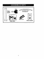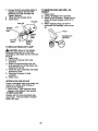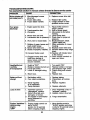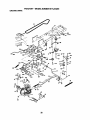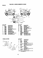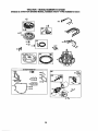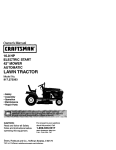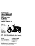
1
Owner's Manual
ICRRFTSMRWI
LAWN TRACTOR
22.0 HP, 42" Mower
Electric Start
Automatic Transmission
Model No.
917.272281
This product has a low emission engine which operates
differently from previously built engines. Before you start the
engine, read and understand this Owner's Manual.
CAUTION:
Read and follow all Safety
Rules and Instructions before
operating this equipment.
For answers to your questions
about this product, Call:
1-800-659-5917
Sears Craftsman Help Line
5 am - 5 pm, Mon - Sat
Seam, Roebuck and Co., Hoffman Estates, II 60179 U.S.A
Visit our Craftsmanwebsite:www.sears.corn/craftsman
Warranty ...............................................
Safety Rules .........................................
Product Specifications ..........................
AssemblyPre-Operation .......................
Operation ............................................
Maintenance .......................................
Maintenance Schedule ...................... 18
Service and Adjustments .................... 22
Storage ............................................... 29
Troubleshooting ................................. 30
Repair Parts ........................................ 34
Sears Service ...................... Back Cover
2
3
6
8
11
18
LIMITED WARRANTY ON CRAFTSMAN RIDING EQUIPMENT
For two (2) years from the date of purchase, if this Craftsman Riding Equipment is
maintained, lubricated and tuned up according to the instructions in the owner's
manual, Sears will repair or replace free of charge any parts that are found to be
defective in material or workmanship according to the guidelines of coverage listed
below. Sears will elsoprovide free labor for these applicable warranted parts for the
two full years. During the first 30 days of purchase, there will be no charges to service
the product at your home for issues covered by this warranty. (See exclusions below).
For your convenience, IN HOME warranty service will still be available after the first 30
days of purchase, but a trip charge will apply. This charge will be waived if the Craftsman product is dropped off at an authodzedSears location. For the nearest authorized
Sears location, please call 1-800-4-MY-HOME_.
This warranty applies only while this
product is within the United States.
This Warranty does not cover:
• Expendable items which become worn during normal use, including but not limited
to blades, spark plugs, air cleaners, belts, and oil filters.
• Standard Maintenance Servicing, oil changes, or tune-ups
• Tire replacement or repair caused by punctures from outside objects, such as nails,
thoms, stumps, or glass.
caused by towing objects beyond the capability of the nding equipment, impacting
i objects
Repairs that
necessary
because
of crankshaft,
operator abuse,
including butthe
notengine.
limited to, damage
bend the
frame or
or over-speedin_
Repairs necessary because of operator negligence, includmg but not limited to,
electrical and mechanical damage caused by improper storage, failure to use the
proper grade and amount of engine oil, failure to keep the deck clear of flammable
debris, or failure to maintain the equipment according to the instructionscontained in
the owner's manual.
• Engine (fuel system) cleaning or repairs caused by fuel determined to be contaminated or oxidized (stale). In general, fuel should be used within 30 days of its
purchase date.
• Normal deterioration and wear of the exterior finishes, or product label replacement.
• Riding equipment used for commercial or rental purposes.
LIMITED WARRANTY ON BA'I-rERY
For ninety (90) days from date of purchase, if any battery included with this riding
equipment proves defective in material or workmanship and our testing determines the
battery will not hold a charge, Sears will replace the battery at no charge. During the
first 30 days of purchase, there will be no charges to replace the battery at your HOME.
After the first 30 days, for your convenience, IN-HOME warranty service will still be
available but a trip charge will apply. This charge will be waived if the Craftsman
product is dropped of at an authorized Sears location. For the nearest authorized
Sears location, please call 1-800-4-MY-HOME®.
This battery warranty applies only while this product is within the United States.
This warranty gives you specific legal rights, and you may also have other rights, which
vary, from state to state.
Sears, Roebuck and Co.,Dept.817WA,
Hoffman Estates, IL 60179
2
IMPORTANT: This cutting machine is capable of amputating hands and feet and
throwing objects. Failure to observe the following safety instructions could result in
serious injury or death.
Look for this symbol to point out
important safety precautions. It means
CAUTION!!I
BECOMEALERTI!!
YOUR
SAFETY IS INVOLVED.
• Do not mow in reverse unless absolutely
necessary. Always look down and
behind before and while backing.
• Be aware of the mower discharge
direction and do not point it at anyone.
Do not operate the mower without either
the entire grass catcher or the guard in
place.
• Slow down before tuming.
• Never leave a running machine
unattended. Always tum off blades, set
parking brake, stop engine, and remove
keys before dismounting.
• Tum off blades when not mowing.
• Stop engine before removing grass
catcher or unclogging chute.
• Mow only in daylight or good artificial
light.
• Do not operate the machine while under
the influence of alcohol or drugs.
• Watch for traffic when operating near or
crossing roadways.
• Use extra care when loading or unloading the machine intoa trailer or truck.
• Data indicates that operators, age 60
years and above, are involved in a large
percentage of riding mower-related
injuries. These operators should
evaluate their ability to operate the riding
mower safely enough to protect themselves and others from serious injury.
• Keep machine free of grass, leaves or
other debris build-up which can touch
hot exhaust / engine parts and bum. Do
not allow the mower deck to plow leaves
or other debris which can cause buildup to occur. Clean any oil or fuel
spillage before operating or storing the
machine. Allow machine to cool before
storage.
_, CAUTION:
In order to prevent
accidental starting when setting up,
transporting, adjusting or making repairs,
always disconnect spark plug wire and
place wire where it cannot contact spark
plug.
,_ CAUTION:
Do not coast down a hill
in neutral, you may lose control of the
tractor.
CAUTION:
Tow only the attachments
that are recommended by and comply
with specifications of the manufacturer of
your tractor. Use common sense when
towing. Operate only at the lowest
possible speed when on a slope. Too
heavy of a load, while on a slope, is
dangerous. "13rescan lose traction with
the ground and cause you to lose control
of your tractor.
_,WARNING:
Engine exhaust, some of
its constituents, and certain vehicle
components contain or emit chemicals
known to the State of Califomia to cause
cancer and birth defects or other reproductive harm.
WARNING: Battery posts, terminals
and related accessories contain lead
and lead compounds, chemicals known
to the State of Califomia to cause cancer
and birth defects or other reproductive
harm. Wash hands after handling.
I. GENERAL OPERATION
• Read, understand, and follow all
instructions in the manual and on the
machine before starting.
• Only allow responsible adults, who are
familiar with the instructions, to operate
the machine.
• Clear the area of objects such as rocks,
toys, wire, etc., which could be picked
up and thrown by the blade.
• Be sure the area is clear of other people
before mowing. Stop machine if anyone
enters the area.
• Never carry passengers.
II. SLOPE OPERATION
Slopes are a major factor related to loss-ofcontrol and tipover accidents, which can result in severe injury or death. All slopes
require extra caution. If you cannot back up
the slope or if you feel uneasy on it, do not
mow it.
3
DO:
• Mow up and down slopes, not across.
• Remove obstacles such as rocks, tree
limbs, etc.
• Watch for holes, ruts, or bumps. Uneven
terrain could overtum the machine. Tall
grass can hide obstacles.
• Use slow speed. Choose a low gear so
that you will not have to stop or shift
while on the slope.
• Follow the manufacturer's recommendations for wheel weights or counterweights to improve stability.
• Use extra care with grass catchers or
other attachments. These can change
the stability of the machine.
• Keep all movement on the slopes slow
and gradual. Do not make sudden
changes in speed or direction.
• Avoid starting or stopping on a slope. If
tires lose traction, disengage the blades
and proceed slowly straight down the
slope.
DO NOT-
• Never carry children. They may fall off
and be seriously injured or interfere
with safe machine operation.
• Never allow children to operate the
machine.
• Use extra care when approaching blind
comers, shrubs, trees, or other objects
that may obscure vision.
IV. SERVICE
• Use extra care in handling gasoline
and other fuels. They are flammable
and vapors are explosive.
-Use only an approved container.
- Never remove gas cap or add fuel
with the engine running. Allow
engine to cool before refueling. Do
not smoke.
-Never refuel the machine indoors.
- Never store the machine or fuel
container inside where there is an
open flame, such as a water heater.
• Never run a machine inside a closed
area.
• Keep nuts and bolts, especially blade
attachment bolts, tight and keep
equipment in good condition.
• Never tamper with safety devices.
Check their proper operation regularly.
• Keep machine free of grass, leaves, or
other debris build-up. Clean oil or fuel
spillage. Allow machine to cool before
storing.
• Stop and inspect the equipment if you
strike an object. Repair, if necessary,
before restarting.
• Never make adjustments or repairs
with the engine running.
• Grass catcher components are subject
to wear, damage, and deterioration,
which could expose moving parts or
allow objects to be thrown. Frequently
check components and replace with
manufacturer's recommended parts,
when necessary.
• Mower blades are sharp and can cut.
Wrap the blade(s) or wear gloves, and
use extra caution when servicing them.
• Check brake operation frequently.
Adjust and service as required.
• Do not tum on slopes unless necessary,
and then, turn slowly and gradually
downhill, if possible.
• Do notmow near drop-offs, ditches, or
embankments. The mower could
suddenly turn over if a wheel is over the
edge of a cliff or ditch, or ifan edge
caves in.
• Do not mow on wet grass. Reduced
traction could cause sliding.
• Do not try to stabilize the machine by
puttingyour foot on the ground.
• Do not use grass catcher on steep
slopes.
III. CHILDREN
Tragic accidents can occur if the operator
is not alert to the presence of children.
Children are often attracted to the
machine and the mowing activity. Never
assume that children will remain where
you last saw them.
• Keep children out of the mowing area
and under the watchful care of another
responsible adult.
• Be alert and tum machine off if children
enter the area.
• Before and when backing, look behind
and down for small children.
4
• Remove obstacles such as recks, tree
limbs, etc.
• Watch for holes, ruts, or bumps.
Uneven terrain could overturn the
machine. Tall grass can hide obstacles.
• Use slow speed. Choose a low gear so
that you will not have to stop or shift
while on the slope.
• Avoid starting or stopping on a slope. If
tires lose traction, disengage the
blades and proceed slowly straight
down the slope.
• If machine stops while going uphill,
disengage blades, shift into reverse
and back down slowly.
• Do not turn on slopes unless necessary, and then, turn slowly and gradually downhill, if possible.
• Be sure the area is clear of other
people before mowing. Stop machine if
anyone enters the area.
• Never carry passengers or children
even with the blades off.
• Do not mow in reverse unless absolutely necessary. Always look down
and behind before and while backing.
• Never carry children. They may fall off
and be seriously injured or interfere
with safe machine operation.
• Keep children out of the mowing area
and under the watchful care of another
responsible adult.
• Be alert and turn machine off if children
enter the area.
• Before and when backing, look behind
and down for small children.
• Mow up and down slopes (15 ° Max),
not across.
5
3RODUCT SPECIFICATIONS
Gasoline
Capacity
and Type:
4 Gallons
Unleaded
Regular
Oil Type
(API-SF-SJ):
SAE 30 (Above 32°F)
SAE 5W-30
(Below 32°F)
Oil Capacity:
4.0 Pints
Spark Plug:
(GAP: .040")
Champion RC12YC
Forward:
Reverse:
Tire Pressure:
Front: 14PSI
Rear:. 10- PSI
Blade Bolt
Torque:
A Repair Agreement is available on this
product. Contact your nearest Sears
store for details.
CUSTOMER
Ground Speed
(MPH):
Charging
System:
Battery:
Please read and retain this manual. The
instructions will enable you to assemble
and maintain your tractor properly.
Always observe the =SAFETY RULES".
REPAIR AGREEMENT
RESPONSIBILITIES
• Read and observe the safety rules.
• Follow a regular schedule in maintaining, cadng for and using your tractor.
• Follow the instructions under "Maintenance" and "Storage" sections of this
owner's manual.
5.5
2.4
,_WARNING:
This tractor is equipped
with an internal combustion engine and
should not be used on or near any
unimproved forest-covered, brushcovered or grass-covered land unless the
engine's exhaust system is equipped with
a spark arraster meeting applicable local
or state laws (if any). If a spark arrester is
used, it should be maintained in effective
working order by the operator.
In the state of California the above is
required by law (Section 4442 of the
Califomia Public Resources Code).
Other states may have similar laws.
Federal laws apply on federal lands. A
spark arrester for the muffler is available
through your nearest Sears service
center (See REPAIR PARTS section of
this manual).
16 Amps @ 3600 RPM
Amp/Hr.
28
Min. CCA: 230
Case Size: U 1R
27-35 Ft. Lbs.
CONGRATULATIONS on your purchase
of a new tractor. It has been designed,
engineered and manufactured to give
you the best possible dependability and
performance.
Should you experience any problem you
cannot easily remedy, please contact a
Sears or other qualified service center.
We have competent, well-trained technicians and the proper tools to service or
repair this tractor.
6
Mower
,__
_Ora, n','_
Leveling
Wrench
For Future Use
Bubble Level
I
Video Cassette
Slope Sheet
7
Your new tractor has been assembled at the factory. Review the video cassette before
you begin.
When right or left hand is mentioned in
this manual, it means, from your point of
view, when you are in the operating
position (seated behind the steering
wheel).
TO REMOVE TRACTOR FROM
CARTON
UNPACK CARTON
1. Remove all accessible loose parts
and parts boxes from carton.
2. Cut, from top to bottom, along lines on
all four comers of carton, and lay
panels flat.
3. Check for any additional loose parts
or cartons and remove.
IMPORTANT: Check for and remove any
staples in skid that may puncture tires
where tractor is to roll off skid.
CHECK
ADJUST SEAT
1. Raise seat and loosen adjustment
knobs.
2. Lower seat into operating position and
sit in seat.
3. Slide seat until a comfortable position
is reached which allows you to press
clutch/brake pedal all the way down.
4. Get off seat without moving its
adjusted position.
5. Raise seat and tighten adjustment
knob securely.
NOTE: You may now roll or ddve your
tractor off the skid. Follow the appropriate
instruction below to remove the tractor
from the skid.
BATTERY
1. Lift hood to raised position,
NOTE: if this battery is put into service
after month and year indicated on label
(label located between terminals) charge
battery for minimum of one hour at 6-10
amps. (See =BA'I-I'ERY" in Maintenance
section of this manual for charging
instructions).
....
" _J*"
..,
"
La
Adjustment
Knob | |
bel
8
REPOSmON
RIGHT REAR GAUGE
WHEEL
For shipping purposes, the right rear
gauge wheel assembly is mounted
upside down on the mower. Remove the
gauge wheel assembly and reinstall from
the bottom as shown. To adjust gauge
wheels, see the Operation section in this
manual.
TO ROLLTRACTOR
OFF SKID (See
Operetion section for location and
function of controls)
1. Press lift lever plunger and raise
attachment lift lever to its highest
position.
2. Release parking brake by depressing
brake pedal.
3. Place freewheel control in disengaged position to disengage transmission (See =TO TRANSPORT" in the
Operation section of this manual).
4. Roll tractor forward off skid.
5. Remove banding holding the deflector
shield up against tractor.
TO DRIVE TRACTOR OFF SKID (See
Operation section for location and
function of controls)
INSTALL MULCHER PLATE
WARNING: Before starting, read,
understand and follow all instructions in
(If previously removed)
the Operation section of this manual. Be
sure tractor is in a well-ventilated area. Be
sure the area in front of tractor is clear of
1. Raise and hold deflector shield in
upright position.
Place front of mulcher plate over front
of mower deck opening and slide into
place, as shown.
3. Hook front latch into hole on front of
mower deck.
4. Hook rear latch into hole on back of
mower deck.
2.
other people and objects.
1. Be sure all the above assembly steps
have been completed.
2. Check engine oil level and fill fuel
tank with gasoline.
3. Place freewheel control in "transmission engaged = position (see =TO
TRANSPORT"
in Operation section of
this manual).
4. Sit on seat in operating position,
depress brake pedal and set the
parking brake.
5. Press lift lever plunger and raise
attachment lift lever to its highest
position.
6. Start the engine. After engine has
started, move throttle control to idle
position.
7. Release parking brake.
8. Slowly depress forward drive pedal
and drive tractor off skid.
9. Apply brake to stop tractor and set
parking brake.
10.Turn ignition key to "STOP" position.
Continue with the instructions that follow.
o o0
Deflector
-_
Mulcher
te
a
Latch
Hooks
CAUTION:
Do not remove deflector
shield from mower. Raise and hold shield
when attaching mulcher plate and allow it
to rest on plate while in operation.
TO CONVERT TO BAGGING OR
DISCHARGING
Simply remove mulcher plate and store in
a safe place. Your mower is now ready for
discharging or installation of optional
grass catcher accessory.
NOTE: It is not necessary to change
blades. The mulching blades are
designed for discharging and bagging
also.
9
CHECK TIRE PRESSURE
The tires on your tractorwereoverinflated
at the factoryfor shippingpurposes.
Correcttire pressureis importantfor best
cutting performance.
• Reducetire pressureto PSI shownin
"PRODUCT SPECIFICATIONS"
of this manual.
section
CHECK DECK LEVELNESS
For best cuffing results, mower housing
should be properly leveled. Sea "TO
LEVEL MOWER HOUSING" in the
Service and Adjustments section of this
manual.
CHECK FOR PROPER POSITION OF
ALL BELTS
See the figures that are shown for
replacing motion and mower blade drive
belts in the Service and Adjustments
section of this manual. Vedfy that the
belts are routed correctly.
CHECK BRAKE SYSTEM
After you learn how to operate your
tractor, check to see that the brake is
properly adjusted. See "TO ADJUST
BRAKE" in the Service and Adjustments
section of this manual.
_CHECKUST
Before you operate your new tractor, we
wish to assure that you receive the best
performance and satisfaction from this
quality product.
Please review the following checklist:
/ All assembly instructionshave been
completed.
,/No remaining loose parts in carton.
/ Battery is propedy prepared and
charged. (Minimum 1 hour at 6 amps).
/ Seat is adjusted comfortably and
tightened securely.
/ All tires are properly inflated. (For
shipping purposes, the tires were
overinflated at the factory).
/ Be sure mower deck is propedy leveled
side-to-side/front-to-rear for best cutting
results. (Tires must be propedy inflated
for leveling).
,/Check mower and ddve belts. Be sure
they are routed propedy around pulleys
and inside all belt keepers.
,/Check wiring. See that all connections
are still secure and wires are properly
clamped.
/ Before driving tractor, be sure freewheel
control is in =transmission engaged"
position (see "TO TRANSPORT" in the
Operation section of this manual).
While learning how to use your tractor, pay
extra attention to the following important
items:
/ Engine oil is at proper level.
/ Fuel tank is filled with fresh, clean,
regular unleaded gasoline.
4' Become familiar with all controls - their
location and function. Operate them
before you start the engine.
/ Be sure brake system is in safe operating condition.
/ It is important to purge the transmission
before operating your tractor for the first
time. Follow proper starting and transmission purging instructions (See "TO
START ENGINE" and "PURGE TRANSMISSION" in the Operation section of this
manual).
10
These symbols may appear on your tractor or in literature supplied with the product.
Leam and understand their meaning.
BATTERY
CAUTION OR
WARNING
REVERSE
FORWARD
ENGINE ON
ENGINE OFF
OIL PRESSURE
LIGHTS ON
[i l\l
FUEL
CHOKE
FAST
SLOW
OVERTE?P
1
0
MOWER HEIGHT
PARKING BRAKE
LOCKED
m
UNLOCKED
MOWER LIFT
H L
ATTACHMENT
CLUTCH ENGAGED
REVERSE
NEUTRAL
o6 o
ATTACHMENT
IGNmON
HIGH
LOW
PARKINGBRAKE
@@@@@
KEEP AREA CLEAR
CLUTCH DISENGAGED
SLOPE HAZARDS
(SEE SAFETY RULES SECTION)
FREE WHEEL
(Automatic Models only)
DANGER, KEEP HANDS AND FEET AWAY
11
KNOWYOUR TRACTOR
READ THIS OWNER'S MANUAL AND SAFETY RULES BEFORE OPERATING
YOUR TRACTOR
Compare the illustrations with your tractor to familiarize yourself with the locations of
various controls and adjustments. Save this manual for future reference.
Hourmeter
Attachment
Clutch Switch
Ignition Switch
Light Switch
Lift Lever Plunger
Ammetel
Attachment
: Lever
Throttle
Drive Pedal
Choke
Brake Pedal
Drive Pedal
Height
Adjustment
Indicator
• .. "
Freewheel
Control
Cruise Control Lever
Parking Brake Lever
Our tractors conform to the safety standards of the
American National Standards Institute.
AMMETER - Indicates charging (+) or
discharging (-) of battery.
ATrACHMENT
CLUTCH SWITCH - Used
to engage the mower blades, or other
attachments mounted to your tractor,
ATrACHMENT
LIFT LEVER - Used to
raise, lower, and adjust the mower deck
or other attachments mounted to your
tractor.
BRAKE PEDAL - Used for braking the
tractor and starting the engine.
CRUISE CONTROL
LEVER - Used to set
forward movement of tractor at desired
speed without holding the forward drive
pedal.
FORWARD DRIVE PEDAL - Used for
forward movement of tractor.
REVERSE DRIVE PEDAL o Used for
reverse movement of tractor.
IGNITION SWITCH - Used for starting and
stopping the engine.
LIFT LEVER PLUNGER - Used to release
attachment lift lever when changing its
position,
LIGHT SWITCH POSITION -Tums the
headlights on and off.
PARKING BRAKE LEVER - Locks clutch/
brake pedal into the brake position.
THROI"rLE
CONTROL - Used for
controlling engine speed.
FREEWHEEL
CONTROL Disengagages transmission for pushing
or slowly towing the tractor with the
engine off.
CHOKE CONTROL - Used for starting
engine.
HOURMETER
- Indicates hours of
operation.
12
The operation of any tractor can result in foreign objects thrown into the
eyes, which can result in severe eye damage. Always wear safety
glasses or eye shields while operating your tractor or performing any
adjustments or repairs. We recommend standard safety glasses or a
wide vision safety mask worn over spectacles.
ENGINE HOW TO USE YOUR TRACTOR
TO SET PARKING BRAKE
• Move throttle control to slow position.
NOTE: Failure to move throttle control to
Your tractor is equipped with an operator
slow position to allow engine to idle
presence sensing switch. When engine
before stopping may cause engine to
is running, any attempt by the operator to
"backfire".
leave the seat without first setting the
• Turn ignition key to "STOP" position
parking brake will shut off the engine.
and remove key. Always remove key
1. Depress brake pedal all the way down
when leaving tractor to prevent
and hold.
unauthodzed use.
2. Pull parking brake lever up and
•
Never use choke to stop engine.
release pressure from brake pedal.
IMPORTANT:
Leaving the ignition switch
Pedal should remain in brake posiin
any
position
other than "STOP" will
tion. Make sure parking brake will
cause
the
battery
to discharge and go
hold tractor secure.
dead.
Attachment
NOTE: Under certain conditions when
"Disengaged"
Cinch Switch
tractor is standing idle with the engine
PosWon
"Engaged"
running, hot engine exhaust gases may
Pos_on
Choke
cause =browning" of grass. To eliminate
Control Ign_on
this possibility, always stop engine when
stopping tractor on grass areas.
Throttle
CAUTION: Always stop tractor comControl
Pedal
pletely, as described above, before
leaving the operator's position.
Position
TO USE THROTTLE
Reverse
Drive
Pedal
Brake Pedal
"Drive"
Postion =Disengaged'
Position
Parking
Brake
"Engaged"
Position
Cruise
Control
Lever
STOPPING
MOWER BLADES • To stop mower blades, push attachment clutch switch in to disengaged
position.
GROUND DRIVE • To stop ground drive, depress brake
pedal all the way down.
IMPORTANT: Forward and reverse drive
pedals return to neutral position when not
depressed.
CONTROL
Always operate engine at full throttle,
• Operating engine at less than full
throttle reduces the battery charging
rate.
• Full throttle offers the best bagging and
mower performance.
TO USE CHOKE CONTROL
Use choke control whenever you are
starting a cold engine. Do not use to start
a warm engine.
• To engage choke control, pull knob out.
Slowly push knob in to disengage.
TO MOVE FORWARD AND
BACKWARD
The direction and speed of movement is
controlled by the forward and reverse
drive pedals.
1. Start tractor and release parking
brake.
2. Slowly depress forward or reverse
drive pedal to begin movement.
Ground speed increases the further
down the pedal is depressed.
13
TO USE CRUISE CONTROL
The cruise control feature can be used
for forward travel only.
1. With forward ddve pedal depressed to
desired speed, move cruise control
lever forward to =SET" position and
hold while lifting your foot off the
pedal, then release the cruise control
lever.
To disengage the cruise control, pull the
lever backward to =OFF" position, or fully
depress the brake pedal.
TO ADJUST
MOWER
CU'I'rlNG
4. Replace retainer spdng into clevis pin.
5. Be sure all gauge wheels are in the
same setting.
IMPORTANT: Be sure to readjust gauge
wheels if you change the cuffing height
of the mower deck.
Retainer
Spring
HEIGHT
The position of the attachment lift lever
determines the cuffing height.
• Grasp lift lever.
• Press plunger with thumb and move
lever to desired position.
The cuffing height range is approximately 1-1/2 to 4". The heights are
measured from the ground to the blade
tip with the engine not running. These
heights are approximate and may vary
depending upon soil conditions,
height of
grass and types of grass being mowed.
• The average lawn should be cut to
approximately 2-1/2 inches dudng the
cool season and to over 3 inches
during hot months.
For healthier and better looking lawns,
mow often and after moderate growth.
• For best cutting performance, grass
over 6 inches in height should be
mowed twice. Make the first cut
relatively high; the second to desired
height.
TO ADJUST
Clevis Pin
TO OPERATE
MOWER
Your tractor is equipped with an operator
presence sensing switch. Any attempt by
the operator to leave the seat with the
engine running and the attachment clutch
engaged will shut off the engine.
1. Select desired height of cut.
2. Start mower blades by engaging
attachment clutch control.
TO STOP MOWER BLADES disengage attachment clutch control.
_CAUTION:
Do not operate the mower
without either the entire grass catcher, on
mowers so equipped, or the deflector
shield in place.
Attachment
Attachment Clutch
Lift Lever High
Pos'dion
Switch =Engaged"
/
Position
GAUGE WHEELS
,:!Z,,.....Low
H
Position
Gauge wheels are properly adjusted
when they are slightly off the ground
when mower is at the desired cutting
height in operating position. Gauge
wheels then keep the deck in proper
position to help prevent scalping in most
terrain conditions.
NOTE: Be sure tractor is on a flat level
surface.
1. Lower mower and adjust mower to
desired cutting height(See 'qO
ADJUST MOWER CU'I-FING HEIGHT"
in this section of manual).
2. Remove retainer spring and clevis pin
which secure each gauge wheel bar.
3. Lower gauge wheels to ground. Raise
gauge wheels slightly to align holes in
bracket and gauge wheel bar and
insert clevis pin. Gauge wheels
should be slightly off the ground.
((_Deflector
;%on
,siUon
TO OPERATE
___
Shield
ON HILLS
CAUTION:
Do not drive up or down hills
with slopes greater than 15 ° and do not
drive across any slope. Use the slope
guide provided at the back of this manual.
• Choose the slowest speed before
starting up or down hills.
• Avoid stopping or changing speed on
hills.
• If stopping is absolutely necessary,
push brake pedal quickly to brake
position and engage parking brake.
14
remove and read oil level. If necessary, add oil until =FULL" mark on
dipstick is reached. Do not over/ill.
For cold weather operation you should
change oil for easier starting]((See the
oil viscosity chart in the Mamtenance
section of this manual).
To change engine oil, see the Maintenance section in this manual.
• To restart movement, slowly release
parking brake and brake pedal.
• Slowly depress appropriate drive pedal
to slowest setting.
• Make all turns slowly.
TO TRANSPORT
When pushing or towing your tractor, be
sure to disengage transmission by
placing freewheel control in freewheeling
position. Freewheel control is located at
the rear drawbar of tractor.
1. Raise attachment liftto highest
position with attachment lift control.
2. Pull freewheel control out and down
into the slot and release so it is held in
the disengaged position.
• Do not push or tow tractor at more than
two (2) MPH.
• To re-engage transmission, reverse
above procedure.
ADD GASOLINE
• Fill fuel tank to bottom of tank filler
neck. Do not overfill. Use fresh, clean,
re.gular unleaded gasoline with a
mmJmumof 87 octane. (Use of leaded
gasoline will increase carbon and lead
oxide deposits and reduce valve life).
Do not mix oil with gasoline. Purchase
fuel in quantities that can be used
. within 30 days to assure fuel freshness.
_CAUTION: Wipe off any spilled oil or
fuel. Do not store, spill or use gasoline
near an open flame.
IMPORTANT: When operating in temperatures below 32°F(0°C), use fresh
clean winter grade gasoline to help
insure good cold weather starting.
_kCAUTION: Alcohol blended fuels
(called gasohol or using ethanol or
methanol) can attract moisture which
leads to separation and formation of
acids during storage. Acidic gas can
damage the fuel system of an engine
while in storage.
To avoid engine problems, the fuel
system should be emptied before storage
of 30 days or longer. Drain the gas tank,
start the engine and let it run untilthe fuel
lines and carburetor are empty. Use fresh
fuel next season. See Storage Instructions for additional information,
Never use engine or carburetor cleaner
products in the fuel tank or permanent
damage may occur.
TO START ENGINE
When startingthe engineforthe firsttime or if
theengine has runout of fuel, it
willtake extra
crankingtimeto movefuel from the tank to
the eng=ne.
1. Be sure freewheel control is in the
transmission engaged position.
2. Sit on seat in operating position,
depress brake pedal and set parking
brake.
3. Move attachment clutch to disengaged position.
4. Move throttle control to fast position
5. Pull choke control out for a cold
engine start attempt. For a warm
engine start attempt the choke control
may not be needed.
Transmission Engaged
Transmlsslon
Dlsengaged
NOTE: To protect hood from damage
when transporting your tractor on a truck
or a trailer, be sure hood is closed and
secured to tractor. Use an appropriate
means of tying hood to tractor (rope, cord,
etc.).
TOWING CARTS AND OTHER ATrACHMENTS
Tow only the attachments that are
recommended by and comply with
specifications of the manufacturer of your
tractor. Use common sense when towing.
Too heavy of a load, while on a slope, is
dangerous. Tires can lose traction with the
ground and cause you to lose control of
your tractor.
BEFORE STARTING THE ENGINE
CHECK ENGINE OIL LEVEL
The engine in your tractor has been
shipped, from the factory, already filled
with summer weight oil.
1. Check engine oil with tractor on level
ground.
2. Remove oil fill cap/dipstick and wipe
clean, reinsert the dipstick and screw
cap tight, wait for a few seconds,
15
NOTE:Beforestarting,readthewarmand
coldstartingprocedures
below.
6. Insertkey into ignitionand tum key
clockwise to start position and release
key as soon as engine starts. Do not
run starter continuously for more than
fifteen seconds per minute. If the
engine does not start after several
attempts, push choke control in, wait a
few minutes and try again. If engine
still does not start, pull the choke
control out and retry.
WARM WEATHER STARTING (50° F and
above)
7. When engine starts, slowly push
choke control in until the engine
begins to run smoothly. If the engine
starts to run roughly, pull the choke
control out slightly for a few seconds
and then continue to push the control
in slowly.
• The attachments and grounddrive can
now be used. If the engine does not accept
the load, rastartthe engineand allowitto
warm up for one minute usingthe choke
as described above.
COLD WEATHER STARTING (50° F and
below)
7. When engine starts, slowly push
choke control in until the engine
begins to run smoothly. Continue to
push the choke control in small steps
allowing the engine to accept small
changes in speed and load, until the
choke control is fully in. If the engine
starts to run roughly, pull the choke
control out slightly for a few seconds
and then continue to push the control
in slowly. This may require an engine
warm-up period from several seconds
to several minutes, depending on the
temperature.
AUTOMATIC TRANSMISSION WARM UP
Before driving the unit in cold weather,
the transmission should be warmed up as
follows:
1. Be sure the tractor is on level ground.
2. Release the parking brake and let the
brake slowly return to operating
position.
3. Allow one minute for transmission to
warm up. This can be done during the
engine warm up period.
• The attachments can be used during
the engine warm-up period after the
transmission has been warmed up and
may require the choke control be
pulled out slightly.
NOTE: If at a high altitude (above 3000
feet) or in cold temperatures (below 32 F)
the carburetor fuel mixture may need to
be adjusted for best engine performance
(see =TO ADJUST CARBURETOR" in the
Service and Adjustments section of this
manual).
PURGETRANSMISSION
CAUTION: Never engage or disengage
freewheel lever while the engine is
running.
To ensure proper operation and psrformanse, it is recommended that the
transmission be purged before operating
tractor for the firsttime. This procedure will
remove any trapped air inside the
transmission which may have developed
during shipping of your tractor.
IMPORTANT: Should your transmission
require removal for service or replacement, it should be purged after reinstallation before operating the tractor.
1. Place tractor safely on level surface
with engine off and parking brake set.
2. Disengage transmission by placing
freewheel control in disengaged
position (See =TO TRANSPORT" in
this section of manual).
3. Sitting in the tractor seat, start engine.
After the engine is running, move
throttle control to slow position.
Disengage parking brake.
4. Depress forward drive pedal to full
forward position and hold for five (5)
seconds and release pedal. Depress
reverse drive pedal to full reverse
position and hold for five (5) seconds
and release pedal. Repeat this
procedure three (3) times.
NOTE: During this step there will be no
movement of drive wheels. The air is
being removed from hydraulicdrive
system.
5. Shutoff engine and set parking brake.
6. Engage transmission by placing
freewheel control in engaged
position (See "TO TRANSPORT" in
this section of manual).
7. Sitting in the tractor seat, start
engine. After the engine is running,
move throttle control to half (1/2)
speed. Disengage parking brake.
8. Drive tractor forward for approximately five feet then backwards for
five feet. Repeat this driving procedure three times.
Your transmission is now purged and
now ready for normal operation.
16
MOWING
TIPS
• Mower should be propedy leveled for
best mowing performance.
See rl'O
LEVEL MOWER HOUSING" in the
Service and Adjustments section of
this manual.
• The left hand side of mower should be
used for trimming.
• Drive so that clippings are discharged
onto the area that has already been
cut. Have the cut area to the right of
the tractor. This will result in a more
even distribution of clippings and more
uniform cutting.
• When mowing large areas, start by
tuming to the right so that clippings will
discharge away from shrubs, fences,
driveways, etc. After one or two
rounds, mow in the opposite direction
making left hand turns until finished.
I (
I _____
tI_
,
__
_-_"_
___---_
I
MULCHING MOWING TIPS
IMPORTANT: For best performance,
keep mower housing free of built-up
grass and trash. Clean after each use.
• The special mulching blade will recut
the grass clippings many times and
reduce them in size so that as they fall
onto the lawn they will disperse into the
grass and not be noticed. Also, the
mulched grass will biodegrade quickly
to provide nutrients for the lawn.
Always mulch with your highest engine
(blade) speed as this will provide the
best recutting action of the blades.
• Avoid cutting your lawn when it is wet.
Wet grass tends to form clumps and
interferes with the mulching action.
The best time to mow your lawn is the
early aftemoon. At this time the grass
has dried and the newly cut area will
not be exposed to the direct sun.
• For best results, adjust the mower
only theheight
top one-third
of the
grass
cutting
so that the
mower
cuts off
blades. For extremely heavy grass,
I
_
• If grass is extremely tall, it should be
mowed twice to reduce load and
possible fire hazard from dried clippings. Make first cut relatively high; the
second to the desired height.
• Do not mow grass when it is wet. Wet
grass will plug mower and leave
undesirable clumps. Allow grass to dry
before mowing.
• Always operate engine at full throttle
when mowing to assure better mowing
performance and proper discharge of
material. Regulate ground speed by
selecting a low enough gear to give the
mower cutting performance as well as
the quality of cut desired.
• When operating attachments, select a
ground speed that will suit the terrain
and give best performance of the
attachment being used.
andreduce
paSSmow
your
slowly,
width o
of cut on each
t
_
Max 1/3,
• Certain types of grass and grass
conditions may require that an area be
mulched a second time to completely
hide the clippings. When doing a
second cut, mow across or perpendicular to the first cut path.
• Change your cutting pattern from week
to week. Mow north to south one week
then change to east to west the next
week. This will help prevent matting
and graining of the lawn.
17
M.,.'rO.A.C,=
SC.,=OU.,=
AS YOU COMPLETE
REGULAR SERVICE
DE DATES
Check Operator Presence
and
T Interlock Systems
R crux+<
_" Loose
Fasteners
_
T
0
V'
IfP
I_s
SharpeNReplace Mower Blades
I_'
t_ 3
Lubrication Chart
V'
Che<_BetmryLewi
1_4
R ClaanBe_w andTermed=
Che¢_ Transaxla
V _
Cooling
IV/
I_
Check V-Belts
c,_ EnCne
O,_,=
V"
=/
Change
r=m_r_e
Oa(w_ o+lat+r)
E ; crmnge
Engineo,(wimomo.
m.-)
If,_
I,_
i/
If,_
GN CtesnAi++Fdtor
Ckwn Air _
InspectMufflar/Spark
Arremr
E _m
I/
R_(. =_
_._
Replace Spark Plug
Replace Air Filter Paper Cartridge
Replace Fuel Filter
1 +Change m¢_ often when opem_g under a heevy toad or
In tdgh aml;+:enttemperatures,
2 +Set'vice _
oltett when operating in dtrly or du,stycond_ons.
GENERAL RECOMMENDATIONS
The warranty on this tractor does not
cover items that have been subjected to
operator abuse or negligence. To receive
fullvalue from the warranty, operator must
maintain tractor as instructed in this
manual.
Some adjustments will need to be made
periodicallyto properly maintain your
tractor.
All adjustments in the Service and
Adjustments section of this manual should
be checked at least once each season.
• Once a year you should replace the
spark plug, clean or replace air filter,
and check blades and belts for wear. A
new spark plug and clean air filter
assure proper air-fuel mixture and help
your engine run better and last longer.
BEFORE EACH USE
1. Check engine oil level.
2. Check brake operation.
3. Check tire pressure.
4. Check operator presence and
interlock systems for proper operation.
5. Check for loose fasteners.
I_
II_=
!1_
3 - Replace blades morn often when mowing _ mmdy Soil
4 - NO( mqu_
If equlppod v_,th malntenanapf_ee
betty+
5 - Tlgh_
front _L_b p_
bo_ to _ n.-IbcL _1L6%
DO not over_hten+
LUBRICATION CHART
Zerk
_)Front Wheel
Beadng
Zerk
Zerk
Wheel
Beadng Zerk
(_ General Purpose Grease
<_ REFERTO Maintenance "ENGINE"SECTION
IMPORTANT:. Do not oil or grease the
pivot points which have special nylon
bearings. Viscous lubricants will attract
dust and dirt that will shorten the life of
the self-lubricating bearings. If you feel
they must be lubricated, use only a dry,
powdered graphite type lubricant
sparingly.
18
TRACTOR
Always observe safety rules when
performing any maintenance.
BRAKE OPERATION
If tractor requires more than six (6) feet
stopping distance at high speed in
highest gear, then brake must be adjusted. (See "TO ADJUST BRAKE" in the
Service and Adjustments section of this
manual).
TIRES
• Maintain proper air pressure in all tires
(See "PRODUCT SPECIFICATIONS"
section of this manual).
• Keep tires free of gasoline, oil, or insect
control chemicals which can harm
rubber.
• Avoid stumps, stones, deep ruts, sharp
objects and other hazards that may
cause tire damage.
NOTE: To seal tire punctures and prevent
flat tires due to slow leaks, tire sealant
may be purchased from your local parts
dealer. Tire sealant also prevents tire dry
rot and corrosion.
OPERATOR
PRESENCE SYSTEM
Be sure operator presence and interlock
systems are working properly. If your
tractor does not function as described,
repair the problem immediately.
• The engine should not start unless the
brake pedal is fully depressed and
attachement clutch control is in the
disengaged position.
• When the engine is running, any
attempt by the operator to leave the
seat without first setting the parking
brake should shut off the engine.
• When the engine is running and the
attachment clutch is engaged, any
attempt by the operator to leave the
seat should shut off the engine.
• The attachment clutch should never
operate unless the operator is in the
seat.
BLADE CARE
For best results mower blades must be
kept sharp. Replace bent or damaged
blades.
BLADE REMOVAL
IMPORTANT:
To ensure proper assembly,
center hole in blade must align with star
on mandrel assembly.
4. Reassemble blade bolt, lock washer
and flat washer in exact order as
shown.
5. Tighten blade bolt securely (27-35 Ft.
Lbs. torque).
IMPORTANT:
Blade bolt is grade 8 heat
treated.
Trailing
Mandrel
F,at L
washar
Lock
(Grade 8"--)_)*
._/'_
C_nter "-_
Hole
*A Grade 8 Heat Treated Bolt Can Be
Identified By Six Lines On The Bolt Head
TO SHARPEN BLADE
NOTE: We do not recommend sharpening blade - but if you do, be sure the
blade is balanced.
Care should be taken to keep the blade
balanced. An unbalanced blade will
cause excessive vibration and eventual
damage to mower and engine.
• The blade can be sharpened with a file
or on a grinding wheel. Do not attempt
to sharpen while on the mower.
• To check blade balance, you will need
a 5/8" diameter steel bolt, pin, or a cone
balancer. (When using a cone balancer, follow the instructions supplied
with balancer.)
NOTE: Do not use a nail for balancing
blade. The lobes of the center hole may
appear to be centered, but are not.
• Slide blade on to an unthreaded
portion of the steel bolt or pin and hold
the bolt or pin parallel with the ground.
If blade is balanced, it should remain in
a horizontal position. If either end of
the blade moves downward, sharpen
the heavy end until the blade is
balanced.
___'
1. Raise mower to highest position to
allow access to blades.
2. Remove blade bolt, lock washer and
flat washer securing blade.
3. Install new or resharpened blade with
trailing edge up towards deck as
shown.
_
Blade
5/8" Bolt or Pin_
Center Hole
BATTERY
Your tractor has a battery charging system
which is sufficient for normal use. However, periodic charging of the battery with
an automotive charger will extend its life.
19
• Keep battery and terminals clean.
• Keep battery bolts tight.
• Keep small vent holes open.
• Recharge at 6-10 amperes for I hour.
NOTE: The original equipment battery on
your tractor is maintenance free. Do not
attempt to open or remove caps or covers.
Adding or checking level of electrolyte is
not necessary.
TO CLEAN BATTERY AND TERMINALS
Corrosion and dirt on the battery and
terminals can cause the battery to "leak"
power.
1. Remove terminal guard.
2. Disconnect BLACK battery cable first
then RED battery cable and remove
battery from tractor.
3. Rinse the battery with plain water and
dry.
4. Clean terminals and battery cable
ends with wire brush until bright.
5. Coat terminals with grease or petroleum jelly.
6. Reinstall battery (See "REPLACING
BATTERY" in the SERVICE AND
ADJUSTMENTS section of this
manual).
TRANSAXLE COOLING
The transmissionfan and cooling fins
should be kept clean to assure proper
cooling.
Do not attempt to clean fan or transmission
while engine is running or while the
transmissionis hot. To prevent possible
damage to seals, do not use high pressure
water or steam to clean transaxle.
• Inspect cooling fan to be sure fan blades
are intact and clean.
• Inspect cooling fins for dirt, grass
clippings and other materials. To
prevent damage to seals, do not use
compressed air or high pressure sprayer
to clean cooling fins.
TRANSAXLE PUMP FLUID
The transexle was sealed at the factory
and fluid maintenance is not required for
the life of the transaxle. Should the
transaxle ever leak or require servicing,
contact a Sears or other qualified service
center.
V-BELTS
Check V-belts for deterioration and wear
after 100 hours of operation and replace if
necessary. The belts are not adjustable.
Replace belts if they begin to slip from
wear.
ENGINE
LUBRICATION
Only use high quality detergent oil rated
with API service classificationSF-SJ.
Select the oil's SAE viscositygrade
according to your expected operating
temperature.
8AE _
F
" 4m
lqD4_ft
.B
, "
GRAD_
.
II
JRK R_N_K i_111_PATI_O K_
I_
41
f_
,
m
,
:co
MEX'r OILCK_E
NOTE: Although multi-viscosityoils
(5W30, 10W30 etc.) improve starting in
cold weather, these multi-viscosityoils will
result in increased oil consumptionwhen
used above 32°R Check your engine oil
level more frequently to avoid possible
engine damage from running low on oil.
Change the oil after every 50 hours of
operation or at least once a year if the
tractor is not used for 50 hours in one year.
Check the crankcase oil level before
starting the engine and after each eight (8)
hours of operation. "13ghten
oil fill cap/
dipstick securely each time you check the
oil level.
TO CHANGE ENGINE OIL
Determine temperature range expected
before oil change. All oil must meet API
service classification SF-SJ.
• Be sure tractor is on level surface.
• Oil will drain more freely when warm.
• Catch oil in a suitable container.
1. Remove oil fill cap/dipstick. Be careful
not to allow dirt to enter the engine
when changing oil.
2. Remove yellow cap from end of drain
valve and install the drain tube onto
the fitting.
Oil Drain Valve
Close_
and
_.-'"
Locked [
"_e_
_
Drain
_jTube
Yellow Ca_
3.
Unlock drain valve by pushing inward
slightly and turning countemlockwise.
4. To open, pull out on the drain valve.
5. After oil has drained completely, close
and lock the drain valve by pushing
inward and turning clockwise until the
pin is in the locked position as shown.
6. Remove the drain tube and replace
the cap onto the end of the drain
20
valve.
CLEAN
7. Refill engine with oil through oil fill
dipstick tube. Pour slowly. Do not
overfill. For approximate capacity see
=PRODUCT SPECIFICATIONS"
section of this manual.
8. Use gauge on oil fill cap/dipstick for
checking level. For accurate reading,
tighten dipstick cap securely onto the
tube before removing dipstick. Keep
oil at =FULL" line on dipstick. Tighten
cap onto the tube securely when
finished.
ENGINE OIL FILTER
Replace the engine oil filter every season
or every other oil change if the tractor is
used more than 100 hours in one year.
AIR FILTER
Your engine will not run properly using a
dirty air filter. Clean the foam pre-cleaner
after every 25 hours of operation or every
season. Service paper cartridge every
100 hours of operation or every season,
whichever occurs first.
Service air cleaner more often under
dusty conditions.
1. Remove knobs and cover.
TO SERVICE
Air screen must be kept free of dirt and
chaff to prevent engine damage from
overheating.
Clean with a wire brush or
compressed air to remove dirt and
stubborn dried gum fibers.
CLEAN
AIR INTAKE/COOLING
AREAS
To insure proper cooling, make sure the
grass screen, cooling fins, and other
external surfaces of the engine are kept
clean at all times.
Every 100 hours of operation (more often
under extremely dusty, dirty conditions),
remove the blower housing and other
cooling shrouds. Clean the cooling fins
and external surfaces as necessary. Make
sure the cooling shrouds are reinstalled.
NOTE:
Operating the engine with a
blocked grass screen, dirty or plugged
cooling fins, and/or cooling shrouds
removed will cause engine damage due
to overheating.
MUFFLER
Inspect and replace corroded muffler and
spark arrester (if equipped) as it could
create a fire hazard and/or damage.
SPARK PLUG(S)
Replace spark plug(s) at the beginning of
each mowing season or after every 100
hours of operation, whichever occurs first.
Spark plug type and gap setting are
shown in =PRODUCT SPECIFICATIONS"
section of this manual.
PRE-CLEANER
2.
3.
4.
Wash it in liquid detergent and water.
Squeeze it dry in a clean cloth.
Saturate it in engine oil. Wrap it in
clean, absorbent cloth and squeeze to
remove excess oil.
NOTE: If very dirty or damaged, replace
pre-cleaner.
TO SERVICE
AIR SCREEN
IN-LINE
CARTRIDGE
FUEL FILTER
The fuel filter should be replaced once
each season. If fuel filter becomes
clogged, obstructing fuel flow to carburetor, replacement is required.
1. With engine cool, remove filter and
plug fuel line sections.
2. Place new fuel filter in position in fuel
line with arrow pointing towards
carburetor.
3. Be sure there are no fuel line leaks
and clamps are propedy positioned.
4. Immediately wipe up any spilled
gasoline.
1. Clean cartddge by tapping gently on
flat surface. If very dirty or damaged,
replace cartddge.
2. Reinstall precleaner cartridge, cover
and secure with knobs.
IMPORTANT:
Petroleum solvents, such
as kerosene, are not to be used to clean
the cartddge.
They may cause deterioration of the cartridge. Do not oil cartridge.
Do not use pressudzed air to clean or dry
cartridge.
Knob_
ClamP_clamp
Fuel Filter
idle
Fr°ea_lean_
21
We do not recommend using a garden
hose to clean your tractor unless the
electdcal system, muffler, air filter and
carburetor are covered to keep water out.
Water in engine can result in a shortened
engine life.
CLEANING
Clean en_line, battery, seat, finish, etc.
of all foreign matter.
Keep finished surfaces and wheels free
of all gasoline, oil, etc.
• Protect painted surfaces with automotive type wax.
I&
WARNING:
AVIOD SERIOUS INJURY, BEFORE PERFORMING ANY
SERVICE ORTOADJUSTMENTS:
1. Depress brake pedal fully and set parking brake.
2. Place attachment clutch in =DISENGAGED" position.
3. Tum ignition key to "STOP" and remove key.
4. Make sure the blades and all moving parts have completely stopped.
5. Disconnect spark plug wire from spark plug and place wire where it cannot
come in contact with plug.
TRACTOR
TO REMOVE
TO INSTALL MOWER
Be sure tractor is on level surface and
mower suspension arms are raised with
attachment lift control. Engage parking
brake.
1. Swing anti-sway bar to left side of
mower deck.
2. Slide mower under tractor with
deflector shield to dght side of tractor.
IMPORTANT:
Check belt for proper
muting in all mower pulley grooves.
3. If equipped, turn height adjustment
knob counterclockwise until it stops.
4. Lower mower linkage with attachment
lift control.
5. Install belt into electdc clutch pulley
groove.
6. Place the suspension arms on
outward pointing deck pins. Retain
with double loop retainer spdng with
loops up as shown.
MOWER
1. Place attachment clutch in =DISENGAGED" position.
2. If equipped, turn height adjustment
knob to lowest setting.
3. Lower mower to its lowest position.
4. Remove retainer spdng holding antisway bar to chassis bracket and
disengage anti-sway bar from bracket.
5. Remove four retainer spdngs from
front plate assembly and remove
plate.
6. Remove retainer spdngs from
suspension arms at deck and disengage arms from deck.
7. Raise attachment lift to its highest
position.
8. Slide mower forward and remove belt
from electric clutch pulley.
9. Slide mower out from under dght side
of tractor.
Front Mower
Bracket
Chassis
Bracket
Clutch Pulley
Front Plate
Retainer
Spring
Single Loop
Retainer Springs
Anti-Sway
Bar
Double Loop
Retainer Springs
Pins
USE PLIERS FOR ]
Front Mower
Bracket
RETAINER SPRINGS I
upI Suspension Arms Double Loop
Retainer Springs (Outward
pointing deck pins)
22
Deflector Shield
7. Install front plate assembly to tractor
suspension brackets and retain with
single loop retainer springs as shown.
8. Position front plate assembly between
front mower brackets. Raise deck and
plate assembly to align holes and
insert flanged pins. Secure pins with
double loop retainer springs between
the plate and mower brackets.
NOTE: To assist in locating hole in
flanged pin, the hole in pin is inline with
notch on head of pin. If necessary, move
mower side-to-side to give space
between plate and mower brackets.
IMPORTANT: Check belt for proper
routing in all mower pulley grooves.
9. Connect anti-sway bar to chassis
bracket under left footrest and retain
with double loop retainer spring.
10. If equipped, turn height adjustment
knob clockwise to remove slack from
mower suspension.
11. Raise deck to highest position.
Brake.,,_
Pedal _
__ _
jootrest
Lift Unk
Adjustment
Nut
Cap
ALTERNATE SIDE-TO-SIDE
ADJUSTMENT METHOD
• Raise mower to its highest position.
• At the midpoint of both sides of mower,
measure height from bottom edge of
mower to ground. Distance =A" on
both sides of mower should be the
same or within 1/4" of each other.
• If adjustment is necessary, make
adjustment on one side of mower only.
• To raise one side of mower, tighten lift
link adjustment nut on that side.
• To lower one side of mower, loosen lift
link adjustment nut on that side.
NOTE: Each full turn of adjustment nut
will change mower height about 1/8".
• Recheck measurements after adjusting.
TO LEVEL MOWER HOUSING
Adjust the mower while tractor is parked
on level ground or driveway. Make sure
tires are properly inflated (See =PRODUCT SPECIFICATIONS" section of this
manual). If tires are over or underinflated,
you will not properly adjust your mower.
SIDE-TO-SIDE ADJUSTMENT WITH
BUBBLE LEVEL
NOTE: If necessary, check side-to-side
surface below tractor for levelness with a
long board and the bubble level.
• Using the lift lever, place mower in
position where no part of the mower,
including gauge wheels, is touching the
ground.
• From left side of tractor, find the level
decal on top of mower and place
bubble level on decal as indicated.
• Mower is level side-to-side when
bubble is between the two lines in the
bubble level.
• If adjustment is necessary, under left
hand footrest, turn lift link adjustment
nut (above yellow cap) in appropriate
direction to bring bubble between the
lines in the bubble level.
• Remove bubble level from mower and
store in a safe place.
Bubble Between
Lines
Left Hand
Bottom Edge of
Mower to Ground
=o_
Bottom Edge of
Mower to Ground
_Adjuslmenl
__
Suspensi°n
Nut
FRONT-TO-BACK
ADJUSTMENT
IMPORTANT:
Deck must be level side-toside. If the following front-to-back adjustment is necessary, be sure to adjust both
front links equally so mower will stay
level side-to-side.
. Bubble Level
Level Decal
23
To obtain the best cutting results, the
mower housing should be adjusted so
that the front is approximately 1/8" to 1/2"
lower than the rear when the mower is in
its highest position.
Check adjustment on right side of tractor.
Measure distance "D" directly in front of
and behind the mandrel at bottom edge of
mower housing as shown.
• Before making any necessary adjustments, check that both front plate links
are equal in length.
• If links are not equal in length, adjust
one link to same length as other link.
• To lower front of mower loosen nut =1£'
on both front links an equal number of
turns.
• When distance =D" is 1/8" to 1/2" lower
at front than rear, tighten nuts "F"
against trunnion on both front links.
• To raise front of mower, loosen nut =F"
from trunnion on both front links.
Tighten nut =E" on both front links an
equal number of tums. The two front
links must remain equal in length.
• When distance =D" is 1/8" to 1/2" lower
at front than roar, tighten nut =F" against
trunnion on both front links.
• Recheck side-to-side adjustment.
Measure distance =D" directly in front of
and behind the mandrel at bottom edge of
mower housing as shown.
• Before making any necessary adjustments, check that both front links are
equal in length.
• If links are not equal in length, adjust
one link to same length as other link.
• To lower front of mower loosen nut "E"
on both front links an equal number of
turns.
• When distance =D" is 1/8" to 1/2" lower
at front than rear, tighten nuts =F"
against trunnion on both front links.
• To raise front of mower, loosen nut =F"
from trunnion on both front links.
Tighten nut =E" on both front links an
equal number of turns. The two front
links must remain equal in length.
• When distance =D" is 1/8" to 1/2" lower
at front than rear, tighten nut =F" against
trunnion on both front links.
• Recheck side-to-side adjustment.
BOTH FRONT PLATE UNKS MUST BE
EQUAL IN LENGTH
Nut $
Nut "E"
Front Plate
Links
TO REPLACE
BELT
Trur don
MOWER
BLADE
DRIVE
The mower blade drive belt may be
replaced without tools. Park the tractor
on level surface. Engage parking brake.
BELT REMOVAL1. Remove mower from tractor (See =TO
REMOVE MOWER" in this section of
manual).
2. Work belt off both mandrel pulleys
and idler pulleys.
3. Pull belt away from mower.
BELT INSTALLATION 1. Work belt around both mandrel
pulleys and idler pulleys
2. Make sure belt is in all pulley grooves
and inside all belt guides.
3. Install mower (See =To Install Mower"
in this section of this manual).
Mandrel
Idler
Mandrel
Mandrel
Pulley
24
TO ADJUST BRAKE
Your tractor is equipped with an adjustable
brake system which is mounted on the
side of the transaxle.
If tractor requires more than six (6) feet
stoppingdistance at high speed in highest
gear on a level dry concrete or paved
surface, then brake must be adjusted.
1. Depress clutch/brake pedal and
engage parking brake.
2. Measure distance between brake
operating arm and nut =A" on brake
rod.
3. If distance is other than 1-3/4", loosen
jam nut and turn nut =A" until distance
becomes 1-3/4". Retighten jam nut
against nut =A".
4. Road test tractor for proper stopping
distance as stated above. Readjust if
necessary. If stopping distance is still
greater than six (6) feet in highest
gear, further maintenance is necessary. Contact a Sears or other
qualified service center.
With parking brake "Engaged"
Nut
J_m Nut
Operating
Do not touch this nut. If further brake
adjustment is necessary contact a Sears or
other qualified service center.
TO REPLACE MOTION DRIVE BELT
Park the tractor on level surface. Engage
parking brake. For assistance, there is a
belt installation guide decal on bottom
side of left footrest.
BELT REMOVAL 1. Remove mower (See =TO REMOVE
MOWER" in this section of manual).
NOTE: Observe entire motion drive belt
and position of all belt guides and
keepers.
2. Disconnect clutch wire harness.
3. Remove clutch locater.
4. Remove belt from stationary idler and
clutching idler.
5. Remove belt downward from engine
pulley and around electric clutch.
6. Pull belt slack toward rear of tractor.
Carefully remove belt upwards from
transmission input pulley and over
cooling fan blades.
7. Remove belt from center span keeper
and pull belt away from tractor.
BELT INSTALLATION 1. Carefully work new belt down around
transmission cooling fan and onto the
input pulley.
2. Slide belt into the center span keeper.
3. Pull belt toward front of tractor and roll
belt around electric clutch and onto
engine pulley.
4. Install belt through stationary idler and
clutching idler.
5. Reinstall clutch locater and tighten nut
securely.
6. Reconnect clutch harness.
7. Make sure belt is in all pulley grooves
and inside all belt guides and keepers.
8. Install mower (See =TO INSTALL
MOWER" in this section of manual).
Electric
Clutch
Clutcho r
Clutching_
Idler
Stationary_
Idler
Center Span 1_"
Keeper
Input Pulley
Transmission
25
Harness
TRANSMISSION
MENT
REMOVAUREPLACE-
Should your transmission require
removal for service or replacement, it
should be purged after reinstallation and
before operating the tractor. See =PURGE
TRANSMISSION"
in the Operation
section of this manual.
TO ADJUST STEERING WHEEL ALIGNMENT
If steering wheel crossbars are not
horizontal (left to dght) when wheels are
positioned straight forward, remove
steering wheel and reassemble with
crossbars hodzontal. Tighten securely.
FRONT WHEEL TOE-IN/CAMBER
The front wheel toe-in and camber are
not adjustable on your tractor. If damage
has occurred to affect the front wheel toein or camber, contact a Sears or other
qualified service center.
TO REMOVE WHEEL FOR REPAIRS
1. Block up axle securely.
2. Remove axle cover, retaining dng and
washers to allow wheel removal (rear
wheels have a square key - Do not
lose).
3. Repair tire and reassemble.
NOTE: On rear wheels only: align grooves
in rear wheel hub and axle. Insert square
key.
4. Replace washers and snap retaining
ring securely in axle groove.
5. Replace axle cover.
NOTE: To seal tire punctures and prevent
fiat tires due to slow leaks, purchase and
use tire sealant from Sears. Tire sealant
also prevents tire dry rot and corrosion.
ff your battery is teo weak to start the engine, it
.shouldbe recharged. (See "BATrERY" in the
MAINTENANCE section of this manual).
ff "jumper cables" are used for emergency
starting, follow this procedure:
IMPORTANT: Your tractor is equipped with a
12 volt system. The other vehicle must also be
a 12 volt system. Do not use your tractor
battery to start other vehiclea.
TO ATTACH JUMPER CABLES 1. Connect one end of the RED cable to
the POSITIVE (+) terminal of each
battery(A-B), taking care not to short
against tractor chassis.
2. Connect one end of the BLACK cable
to the NEGATIVE (-) terminal (C) of
fully charged battery.
3. Connect the other end of the BLACK
cable (D) to good chassis ground,
away from fuel tank and battery.
TO REMOVE CABLES, REVERSE ORDER 1. BLACK cable first from chassis and
2.
Weak or Dead
Battery
REPLACING
Square Key
_'
(Rear Wheel Only)
ENGINE
Fully Charged
Battery
BATTERY
_WARNING:
Do not short battery
terminals by allowing a wrench or any
other object to contact both terminals at
the same time. Before connecting battery,
remove metal bracelets, wristwatch
bands, rings, etc.
Positive terminal must be connected first
to prevent sparking from accidental
grounding.
1. Lift hood to raised position.
2. Remove terminal guard.
3. Disconnect BLACK battery cable then
RED battery cable and carefully
remove battery from tractor.
4. Install new battery with terminals in
same position as old battery.
5. Reinstall terminal guard.
6. First connect RED battery cable to
positive (+) battery terminal with hex
bolt and keps nut as shown. Tighten
securely.
Washers
Retaining
Ring
Axle
Cover
TO START
BATI'ERY
then from the fully charged battery.
RED cable last from both batteries.
WITH A WEAK
e_kWosA.RNING:
ead-acidbatterissgenerate
h/egasas. LKeep
sparks,flame and
smokingmaterialsaway from batteries.
Always wear eye protectionwhen around
battedes.
26
7. ConnectBLACKgroundingcable to
negative(-) batteryterminalwith
remaininghex bolt and keps nut.
Tightensecurely
8. Closeterminalaccessdoors.
9, Close hood.
HexBolt
KepsNut
Terminal
TO REMOVE HOOD AND GRILL ASSEMBLY
1. Raise hood.
2. Unsnap headlight wire connector.
3. Stand in front of tractor. Grasp hood at
sides, tilt toward engine and lift off of
tractor.
4. When replacing hood, be sure to
reconnect the headlight wire connector.
Door
Cable
Guard
TO REPLACE
,Negative
(Black)
Cable
HEADLIGHT
LAMP
CAUTION: When lit, the halogen
lamps get extremely hot. Hold lamp
assembly by the holder and do not touch
the bulb.
1. Raise hood.
2. Disconnect harness from lamp
assembly.
3. Rotate counterclockwise and pull
lamp assembly out of the hole in the
backside of the grill.
4. Insert new lamp assembly and rotate
clockwise to lock.
5. Reconnect harness to lamp
assembly.
6. Close hood.
INTERLOCKS
AND RELAYS
Loose or damaged widng may cause your
tractor to run poorly, stop running, or
prevent it from starting.
• Check wiring. See electrical wiring
diagram in the Repair Parts section.
TO REPLACE FUSE
Replace with 20 amp automotive-type
plug-in fuse. The fuse holder is located
behind the dash.
27
ENGINE
Maintenance, repair, or replacement of the
emission control devices and systems, which
are being done at the customers expense,
may be performed by any non-road engine
repair establishment or individual. Warranty
repairs must be performed by an authorized
engine manufacturer's service outJeL
TO ADJUST THROTTLE CONTROL
CABLE
The throttle control has been preset at the
factory and adjustment should not be
necessary. Check adjustment as described below before loosening cable. If
adjustment is necessary, proceed as
follows:
1. With engine not running, move throttle
control lever to fast position.
2. Check that swivel is against stop. If it is
not, loosen cable clamp screw and
pull cable back until swivel is against
stop. Tighten cable clamp screw
securely.
TO ADJUST CHOKE CONTROL
TO ADJUST CARBURETOR
Your carburetor is not adjustable. If your
engine does not operate properly due to
suspected carburetor problems, take your
tractor to an authorized service canter for
repair and/or adjustment.
High speed stop is factory adjusted. Do
not adjust - damage may result.
IMPORTANT: Never tamper with the
engine govemor, which is factory set for
proper engine speed. Overspeeding the
engine above the factory high speed
setting can be dangerous. If you think the
engine-govemed high speed needs
adjusting, contacta Sears or otherqualified
se_ce center,, which has proper equipment and experience to make any
necessary adjustments.
The choke control has been preset at the
factory and adjustment should not be
necessary. Check adjustment as described below before loosening cable. If
adjustment is necessary, proceed as
follows:
1. With engine not running, move choke
control (located on dash panel) to full
choke position.
2. Loosen knob and remove cover
assembly from air cleaner.
3. Choke should be closed. If it is not,
loosen casing clamp screw and move
choke cable until choke is completely
closed. Tighten casing clamp screw
securely.
4. Replace air cleaner cover assembly
and tighten knob.
Clamp
Screw
28
Immediately prepare your tractor for
storage at the end of the season or if the
tractor will not be used for 30 days or
more.
,_ CAUTION:
Never store the tractor
with gasoline in the tank inside a building
where fumes may reach an open flame or
spark. Allow the engine to cool before
storing in any enclosure.
TRACTOR
Remove mower from tractor for winter
storage. When mower is to be stored for
a period of time, clean it thoroughly,
remove all dirt, grease, leaves, etc. Store
in a clean, dry area.
1. Clean entire tractor (See "CLEANING"
in the Maintenance section of this
manual).
2. Inspect and replace belts, if necessary
(See belt replacement instructions in
the Service and Adjustments section
of this manual).
3. Lubricate as shown in the Maintenance section of this manual.
4. Be sure that all nuts, bolts and screws
are securely fastened. Inspect moving
parts for damage, breakage and wear.
Replace if necessary.
5. Touch up all rusted or chipped paint
surfaces; sand lightly before painting.
BATI'ERY
• Fully charge the battery for storage.
• After a period of time in storage, battery
may require recharging.
• To help prevent corrosion and power
leakage during long periods of storage,
battery cables should be disconnected
and battery cleaned thoroughly (see
_1"OCLEAN BA'I-I'ERY AND TERMINALS_ in the Maintenance section of
this manual).
• After cleaning, leave cables disconnected and place cables where they
cannot come in contact with battery
terminals.
• If battery is removed from tractor for
storage, do not store battery directly on
concrete or damp surfaces.
ENGINE
FUEL SYSTEM
Also, alcohol blended fuels (called
gasohol or using ethanol or methanol)
can attract moisture which leads to
separation and formation of acids during
storage. Acidic gas can damage the fuel
system of an engine while in storage.
1. Drain the fuel tank.
2. Start the engine and let it run until the
fuel lines and carburetor are empty.
• Never use engine or carburetor cleaner
products in the fuel tank or permanent
damage may occur.
• Use fresh fuel next season.
NOTE: Fuel stabilizer is an acceptable
alternative in minimizing the formation of
fuel gum deposits during storage. Add
stabilizer to gasoline in fuel tank or
storage container. Always follow the mix
ratio found on stabilizer container. Run
engine at least 10 minutes after adding
stabilizer to allow the stabilizer to reach
the carburetor. Do not drain the gas tank
and carburetor if using fuel stabilizer.
ENGINE OIL
Drain oil (with engine warm) and replace
with clean engine oil. (See =ENGINE" in
the Maintenance section of this manual).
CYLINDER(S)
1. Remove spark plug(s).
2. Pour one ounce of oil through spark
plug hole(s) into cylinder(s).
3. Turn ignition key to start position for a
few seconds to distribute oil.
4. Replace with new spark plug(s).
OTHER
• Do not store gasoline from one season
to another.
• Replace your gasoline can if your can
starts to rust. Rust and/or dirt in your
gasoline will cause problems.
• If possible, store your tractor indoors
and cover it to give protection from dust
and dirt.
• Cover your tractor with a suitable
protective cover that does not retain
moisture. Do not use plastic. Plastic
cannot breathe which allows condensation to form and will cause your
tractor to rust.
IMPORTANT:
Never cover tractor while
engine and exhaust areas are still warm.
IMPORTANT:
It is important to prevent
gum deposits from forming in essential
fuel system parts such as carburetor, fuel
hose, or tank during storage.
29
TROUBLESHOOTING CHART:.
See appropriate section In manual unless directed to Sears service center
PROBLEM
Will not start
Hard to start
CORRECTION
CAUSE
1. Fill fuel tank.
2. See "TO START ENGINE"
in Operation section.
3. Wait several minutes before
attempting to start.
4. Replace spark plug.
4. Bad spark plug.
5. Dirty air filter.
5. Clean/replace air filter.
6. Dirty fuel filter.
6. Replace fuel filter.
7. Water in fuel.
7. Drain fuel tank and carbure
tor, refill tank with fresh
gasoline and replace fuel
filter.
8. Loose or damaged wiring.
8. Check all wiring.
9. Carburetor out of adjustment. 9. See "To Adjust Carburetor"
in Service and Adjustments
section.
lO.Contact
a Sears or other
10. Engine valves out of
adjustment.
qualified service center.
1. Out of fuel.
2. Engine not "CHOKED"
properly.
3. Engine flooded.
1.
2.
3.
4.
5.
Dirty air filter.
Bad spark plug.
Weak or dead battery.
Dirty fuel filter.
Stale or dirty fuel.
6.
7.
Loose or damaged wiring.
Carburetor out of adjustment.
8. Engine valves out of
adjustment.
Engine will not
turn over
1. Brake pedal not
depressed
2. Attachment clutch is
engaged.
3. Weak or dead battery.
4. Blown fuse.
5. Corroded battery terminals.
6. Loose or damaged wiring.
7. Faulty ignition switch.
1.
2.
3.
4.
5.
Clean/replace air filter.
Replace spark plug.
Recharge or replace battery.
Replace fuel filter.
Drain fuel tank and refill with
fresh gasoline.
6. Check all wiring.
7. See "To Adjust Carburetor" in
Service and Adjustments
section.
8. Contact a Sears or other
qualified service center.
1. Depress brake pedal.
9. Faulty operator presence
switch(es).
2. Disengage attachment
clutch.
3. Recharge or replace battery.
4. Replace fuse.
5. Clean battery terminals.
6. Check all wiring.
7. Check/replace ignition
switch.
8. Check/replace solenoid or
starter.
9. Contact a Sears or other
qualified service center.
Engine clicks but
will not start
1.
2.
3.
4.
2. Clean battery terminals.
3. Check all wiring.
4. Check/replace solenoid or
Loss of power
1. Cutting too much grass/too
1. Set in "Higher Cut" position/
fast.
reduce speed.
2. Throttle in =CHOKE" position. 2. Adjust throttle control.
8.
Faulty solenoid or starter.
Weak or dead battery.
Corroded battery terminals.
Loose or damaged wiring.
Faulty solenoid or starter.
,
Recharge
or replace battery.
starter.
3O
TROUBLESHOOTING CHART:
See appropriate section in manual unless directed to Sears service center
PROBLEM
CAUSE
CORRECTION
Loss of power
contlnued)
3. Build-up of grass, leaves
and trash under mower.
4. Dirty air filter.
5. Low oil level/dirty oil.
6. Faulty spark plug.
3.
7. Dirty fuel filter.
8. Stale or dirty fuel.
9. Water in fuel.
10.Spark plug wire loose.
11. Dirty engine air screen/fins.
12. Dirty/clogged muffler.
13. Loose or damaged wiring.
14. Carburetor out of
adjustment.
15. Engine valves out of
adjustment.
Excessive
vibration
1. Worn, bent or loose blade.
2. Bent blade mandrel.
3. Loose/damaged part(s).
Engine continues
Io run when
)perator leaves
seat with
_ttachment
1. Faulty operator-safety
presence control system.
Clean underside of mower
housing.
4. Clean/replace
air filter.
5. Check oil level/change oil.
6. Clean and regap or change
spark plug.
7. Replace fuel filter.
8. Drain fuel tank and refill
with fresh gasoline.
9. Drain fuel tank and
carburetor, refill tank with
fresh gasoline and replace
fuel filter.
10.Connect and tighten spark
plug wire.
11 .Clean engine air screen/
fins.
12.Clean/replace
muffler.
13.Check all widng.
14.See "To Adjust Carburetor"
in Service and Adjustments
section.
15.Contact a Sears or other
qualified service center.
1. Replace blade.
Tighten blade bolt.
2. Contact a Sears or other
qualified service center.
3. Tighten loose part(s).
Replace damaged parts.
,
Check wiring, switches and
connections. If not corrected
contact a Sears or other
qualified service center.
:lutch engaged
_oorcut-uneven
1. Worn, bent or loose blade.
2.
3.
4.
,
• owerbladeswlil
not rotate
Mower deck not level.
Buildup of grass, leaves,
and trash under mower.
Bent blade mandrel.
Clogged mower deck vent
from build-up of grass,
leaves, and trash around
mandrels.
1. Obstruction in clutch
mechanism.
31
1. Replace blade. Tighten
blade bolt.
2. Level mower deck.
3. Clean underside of mower
housing.
4. Contact a Sears or other
qualified service center.
5. Clean around mandrels to
open vent holes.
1. Remove obstruction.
TROUBLESHOOTING CHART:
See appropriate section in manual unless directed to Sears service center
PROBLEM
Mower blades will
not rotate (con't)
CAUSE
CORRECTION
2. Worn/damaged mower
drive belt.
3. Frozen idler pulley.
4. Frozen blade mandrel.
1. Engine speed too slow.
Headlight(a) not
working
(if so equipped)
1. Switch is =OFP.
2. Bulb(s) or lamp(s) bumed out.
3. Faulty light switch.
4. Loose or damaged wiring.
5.
Loss of drive
Blown fuse.
1. Turn switch =ON'.
2. Replace bulb(s) or lamp(s).
3. Check/replace
light switch.
4. Check wiring and connections.
5. Replace fuse.
1. Bad battery cell(s).
2. Poor cable connections.
1. Replace battery.
2. Check/clean all connections.
3.
Faulty regulator
(if so equipped).
4. Faulty alternator.
3.
1. Freewheel control in
1. Place freewheel control in
=engaged" position.
2. Replace motion drive belt.
Replace
regulator.
4. Replace alternator.
=disengaged" position.
2. Motion drive belt wom,
damaged, or broken.
3. Air trapped in transmission
during shipment or
servicing.
Engine "backfires"
whenturnlng
engine
"OFF"
3. Replace idler pulley.
4. Contact aSears or other
qualified service center.
1. Place throttle control in
=FAST" position.
2. Shift to slower speed.
2. Travel speed too fast.
3. Wet grass.
3. Allow grass to dry before
mowing.
4. Mower deck not level.
4. Level mower deck.
5. Low/uneven tire air pressure 5. Check tires for proper air
pressure.
6. Wom, bent or loose blade.
i6. Replace/sharpen blade.
Tighten blade bolt.
7. Buildup of grass, leaves and 7. Clean underside of mower
trash under mower.
housing.
8. Mower drive belt worn.
8. Replace mower drive belt.
9. Blades improperly installed. 9. Reinstall blades sharp edge
down.
10.1mproper blades used.
10. Replace with blades listed
in this manual.
11.Clean around mandrels to
11.Clogged mower deck vent
holes from buildup of
open vent holes.
grass, leaves, and trash
around mandrels.
Poor grass
discharge
Battery will not
charge
2. Replace mower drive belt.
1. Engine throttle control not
set at "SLOW _
position for 30 seconds
before stopping engine.
32
3.
.
Purge transmission.
Move throttle control to
=SLOW" position and allow
to idle for 30 seconds before
stopping engine.
TRACTOR -- MODEL NUMBER 917.272281
SCHEMATIC
SEAT SWITCH
(NOT OCCUPIED)
,
KUE
i
i
!
LINE J
FUEL =
'
'b
......
i__
FUELSHUT-OFF
(IF SO EQUIPPED)
L-_--J
_ .........
A
_
RELAY#t
IGNITION
UNiT
_
I
LIGHTS
LIC
=
OPERATORPRESENCE
PLUG
GAP
SPARK
PLUGSON
_ _ CYL
ENGINES)
PTO SWITCH
,
F
C+GeB+H
IGNmON SWITCH
GFC
REMOVABLE
NON-REMOVABLE
CONNECTIONS
CONNECTIONS
WIRING INSULATED CLIPS
NOTE: IF WIRING INSULATED GLIPS WERE REMOVED FOR
SERVICING OF UNIT, THEY SHOULD BE REPLACED TO
PROPERLY SECURE YOUR WIRING.
33
DA
TRACTOR -- MODEL NUMBER 917.272281
ELECTRICAL
if
40
i !
j!
I
f
26
I
I
I
J
34
TRACTOR -- MODEL NUMBER 917.272281
ELECTRICAL
KEY PART
NO. NO.
DESCRIPTION
1
2
8
10
11
12
16
21
24
25
26
27
28
29
30
33
40
41
42
43
45
46
50
55
79
81
Battery
Bolt, Hex 1/4-20 x 3/4
Tray, Battery
Bolt, Btr Front 1/4-20 x 7-1/2
Holddown Battery Front Mount
Nut, Push Nylon Battery Front 1/4
Switch Intedock
Harness, Light
Cable, Battery
Cable, Battery
Fuse
Nut Keps He)( 1/4-20 UNC
Cable, Ground
Switch, Seat
Switch, Ignition
Key
Harness, Ignition
Bolt Fin He)( 1/4-20 Unc x 1/2
Cover,Terminal
Solenoid
Ammeter
Hourmeter
Switch Pto
Scrow Thdrol 5116-18x 1/2
Lamp and HolderAsm
ReleyAsm
163465
74760412
7603J
145211
150109
145769
176138
175449
4799J
146148
175158
73510400
145491
160784
175442
175447
179737
71110408
131563
178861
175500
177501
178461
17490508
175448
109748X
NOTE: All component dimensionsgiven in U.S. inches
1 inch = 25.4 mm
35
TRACTOR - - MODEL NUMBER 917.272281
CHASSISAND ENCLOSURES
42
29
215
39
166
2O
23
2O9
2OO
3
2O9
36
TRACTOR-CHASSIS AND ENCLOSURES
MODEL NUMBER
KEY PART
NO. NO.
1
2
3
9
11
10
13
14
17
20
23
25
26
28
29
30
31
37
38
39
42
43
58
60
64
74
90
142
143
144
145
154
155
158
159
166
206
209
215
217
219
174619
176554
17060612
172542)(418
174996
72140608
179174X010
17490608
172540X615
180679
124028X
19131312
STD541437
174945X418
174944X418
179131X615
139976
17490508
175710
174988
172545X599
172544X599
174993
STD533707
174997
STD541437
124346X
17570_
154966
175582
156524
174679
174680
1620_7
179950X418
164863
170165
17000612
172543X615
179132X418
17000512
917.272281
DESCRIPTION
Chassis
Screw, 3/8-16 x 3/4
Dash
Panel, Dash, I_H
Bolt 3/8-16 x 1
Panel, Dash, RH
Screw Thdrol 3/8-16 x 1/2
HoodAssembly
Plate Battely
BushingSnap
Washer 13/32 x 13/16 x 12 Gauge
Locknut,Hex, with Insert 3/8-16 UNC
Grille
LightboxDual
Fender/Footrest
Bracket,Fender/Support
Screw, Thdrol. 5/16-18 x 1/2 TYT
BracketAsm Pivot Mower Rear
Bracket Pivot Hood
Lens I.h
Lens Rh
Duct Hood
BoltRdhd Sqnk3/8-16UNCx3/4
Dash Lower
NutCrownlock3/8-16 UNC
Nut Self Thd Wsh Hd 1/4
Plate Reinforcement
Bracket Swaybar Chassis
Bracket Footrest
Rod PivotChassis/Hood
Bracket Dash Rh
Bracket Dash Lh
Parking Brake Bkrt
CupholderStlBIk
HWHDH:-Lo.#13-16 x3/4
BoltShoulder 5/16-18
Screw HexwshThdr 3/8-t 6 x 3/4
Bumper
ConsoleFuelWindowStlt
ScrewS/16-18x3/4
NOTE: Allcomponent dimensionsgiven in U.S. inches
1 inch= 25.4 mm
37
TRACTOR -- MODEL NUMBER 917.272281
GROUNDDRIVE
244
226
62
36
32
_52
253
22
24
77
26
26
F
241
38
TRACTOR -- MODEL NUMBER 917.272281
GROUNDDRIVE
KEY PARr
NO. NO.
1
6
9
15
16
17
19
20
21
22
24
25
26
27
28
29
30
:_
33
34
35
36
37
38
39
41
47
48
49
50
51
52
53
55
56
57
59
61
62
63
65
66
74
75
76
......
DESCRIPTION
Transaxle (See Breakdown)
Hydrogear Model 323-O510
17060512
Screw 5/16-16 x 3/4
137140
Clutch Elec
74490544
BoltHe)( Flghd 5/16-18 Gr. 5
_
Nut Lock Hex W/Ins. 5/16-18 Unc
126197X
Washer 1-1/20D x 15/32 ID x
.250
73800600
NutLockHexW/Wsh 3/6-16Unc
150P_80
Bolt Hex 7/16-20 x 4 x 1/4
175036X505 KnobCustaroControlCruise
175896
Rod, Brake
73350600
Nut, He:<Jam 3/6-16 Uoc
106888X
Spring,Brake Rod
19131316
Washer
760_0412
Pin Cotter 1/8 x 3/4 CAD.
179607
Rod, Parking Brake
179608X505 KnobBrake Parking
16..o592
Bracket, Transaxle
74760512
BoltHexHd 5/16-18Uncx3/4
72140506
Bolt Rdhd Sqnk 5/16-18 Unc x 3/4
175578
Shaft, Foot Pedal
120183X
Boedng, Nylon
19211616
Washer
1572H
Pin, Roll
179114
Pulley, Composite
74760648
Bolt Fin He)( 3/8-16 Unc x 3
175556
Keeper, Belt Idler Flat
127783
Pulley, Idler, V-Groove
154407
BellcrankClutch Gmd Drw Stl
123205X
Retainer, Belt
74760624
Bolt
73680600
NutCrownlock 3/8-16UNC
73680500
NUt,Crownlock 5/16-18 Unc
10b-'/10X
Link, Clutch
105709X
Spring, Retum, Clutch
17060620
Screw 3/8-16 x 1-1/4
140_294
V-Belt, Ground Drive
169691
Keeper, Center Span
17120614
Screw 3/8-16 x .875
123533
Cover, Pedal
175417
Pulley, Engine
10040700
Washer
154778
Keepor Bait Engine
137057
Spacer, Axle
121749X
Washer 25/32 x 1-1/4 x 16 Ga.
12000001
E-Ring
KEY PART
NO. NO.
DESCRIPTION
77
78
89
90
95
96
116
120
150
151
202
212
214
215
217
218
219
_
221
222
223
224
225
226
227
228
229
231
232
233
234
235
236
237
238
239
240
241
242
243
244
250
253
254
Key, Square
Washer 25/32 x 1-5/8 x 16 Ga.
Console, Shift
NUtSeff-Thd Wsh-hd 1/4 Zinc
Rod Bypass
Retainer Spring 1' Zinc/Cad
Belt RDHD SQNK 3/8-16 Unc x 1
NUt Lock Rg 3/8-16 Unc
Spacer Retainer
Washer 13/32 x 2 x 10 Ga.
Bolt Carr Sh 3/8-16 x 1-1/2 Gr. 5
NUtHexFlange Lock
LinkTraneaxle
Cover Pedal Forward
Pedal Reverse Asm. w/Pad
Arm ControlPedal Reverse
Bracket Frast Pdl Ctrl. Hyd
Bracket Mtg. Pedal Control
Bolt Rdhd Sqnk 3/8-16 Uric x 3/4
NUtCrownlock 7116-14 Unc
Washer Nylon 11/16 ID x .060
PedalForward
Arm ControlPedal Forward
Bolt Pivot Spacer
Cam ReverSe Pedal LT
Bolt Shoulder5/16-18
Washer Serrated 5/16 x .75
StrapTorque
Actuator Cruise Disengage
PawlControlCruise
LeverControlCruise
Sector ControlCruise
Bolt Shoulder 3/6-16 Unc 1/44
Bolt Shoulder5/16-18
Arm Mtg. Cruise Sector
Screw Thdrol 5/16 x 1/2
Spdng Return CruiseControl
Nut Cantarlock 1/4-20 Unc
Bolt Fin Hex 1/4-20 Unc x 3/4
BracketAnti-Rotation CVX
Screw 5/16-18 x 5/8 Yellow
Screw 3/8-16 x 3/4
Washer .3125 x .615 x 16 Ga.
Clip Retainer
123583X
121748X
174901X418
124346X
180825
4497H
72140608
73900600
175456
19133210
72110612
145212
174735
175646
179433
174713
174839
174711
72140606
73680700
174840
174736
174712
174902
174710
179032
176451
174573
175570
174856
174858
174857
128903
170165
175807
17490508
175610
73930400
74780412
178289
166880
17060612
179422
178062
NOTE: All component dimensionsgiven in U.S. inches
1 inch = 25.4 mm
39
TRACTOR -- MODEL NUMBER 917.272281
STEERINGASSEMBLY
88
J
67
I
29
43
4o
lO
40
36
TRACTOR - - MODEL NUMBER 917.272281
STEERING ASSEMBLY
KEY PART
NO. NO.
DESCRIPTION
1
2
3
4
5
6
8
10
11
12
13
15
17
29
32
33
34
35
36
37
38
40
41
42
43
46
65
67
68
71
72
82
87
88
91
StasdngWheel
Axle Assembly
Spindle Assembly, LH.
Spindle Assembly, R.H.
Bearing, Race, Thrust, Hardened
Washer 25/32 x 1o5/8x 16 Gauge
Ring, Klip
Draglink
Washer, Lock
Nut I.-lexJam Toplock 1/2-20 Unf
Spacer Brg Axle Front
Nut Hexflange Lock
Shaft Assembly, Steedng
Screw, 3/8-16 x 3/4
Red,Tie
Washer 11/32 x 3/4 x 16 Ga.
Washer Lock Hvy Spr. 5/16
CrownlockNut5/16-24 Unf
Bushing,Stasdng
Screw
Insert, Stasnng Wheel
Nut Lock Center 3/8-24 Unf
Adaptor, Steedng Wheel
Boot, Steering Shaft
Washer 25/32 x t-1/4 x 16 Gauge
Cap, Spindle
Spacer Brace Axle
Bolt Rdhd Bq 3/8-16 UNC x 2-1/4
Axle, Brace
SteeringAsm
Washer 9116 Id x Iol/20d 11G Zin
Bracket Susp Chassis Front
Washer Fiat .781 x 1-1/2 x .14
BoltShoulder 7/16-20 Unc
ClipSteedng
175139X418
172393
169840
169839
6266H
121748X
12000029
175121
STD551137
7394.9800
136518
145212
177883
17060612
170162
19111216
STITo51131
73540500
155105
152g_7
175140X418
ST0541537
159945
174530X418
121749X
121232X
160_67
72140618
169827
175146
19182411
169835
173966
175118
1755,53
NOTE: Allcomponent dimensionsgiven in U.S. inches
1 inch = 25.4 mm
41
TRACTOR -- MODEL NUMBER 917.272281
ENGINE
14
38
32
I
29
I OPTIONAL
EQUIPMENT
Spark Arrester
I
42
TRACTOR -- MODEL NUMBER 917.272281
ENGINE
KEY PART
NO. NO.
1
2
3
4
5
6
8
10
13
14
16
17
23
25
26
29
31
32
33
37
38
41
45
62
72
81
112
DESCRIPTION
175437X505 ContmI, Throffia
164863
Screw Hwhd H.-Lo #13016 x 3/4
.......
Engine, (See Breakdown) B&S Model Number
446777-0165-E1
149723
Muffler
159955
Pipe Exhaust Lh
160589
Pipe Exhaust Rh
171877
Bolt 5/16-18 Unc x 3/4
162797
Shield Heet
165391
Gasket
(See Engine Breakdown)
148456
Tube Drain Oil Easy
11050600
Washer, Lock, External Tooth 3/8
17060624
Screw 3/8-16 x 1-1/2
169837
Shield, Browning/ Debris Guard
175440X505 Choke Control
"/3920600
Nut, Keps 3/8-24 Unf
137180
Kit, Spark Arrestor
179022
Tank Fuel
179124X418 CapAsm Fuel
123487X
Clamp, Hose
8543R
Line, Fuel
148315
Plug Drain Oil Easy
139277
Stem Fuel Tank
17000612
Screw HexwshThdr 3/6-16 x 3/4
10040500
Washer Lock 5/16
71070512
Screw Hex Cap 5/16-18 x 3/4
73510400
Nut Keps Hex 1/4-20 UNC
3645,.I
Bushing
NOTE: Allcomponent dimensionsgiven in U.S. inches
1 inch = 25.4 mm
43
TRACTOR- - MODEL NUMBER 917.272281
SEATASSEMBLY
KEY PART
NO. NO.
DESCRIPTION
1
2
3
4
5
5
7
8
9
10
11
12
13
Seat
Bracket, Pivot, Seat
Bolt
Washer 13/32 x 1 x 10 Gauge
Clip, Push-In Hinged
Nut
Spdng, Seat
Screw 3/8-16 x 1-1/2
Washer 13/32 x 1 x 14 Gauge
Pan, Seat
Knob Seat
Bracket, Switch Mounting
Bushing,Snap
175134
14O551
71110616
19131610
145OO6
STD541437
124181X
17000616
19131614
182493
177957
121246X
121248X
KEY PART
NO. NO,
14
15
16
17
18
21
22
24
72050412
121249X
123740X
12397'6X
124238X
171852
STD541431
19171912
25
127018X
DESCRIPTION
Bolt, Carriage 1/4-20 x 1-1/2
Spacer, Split
Spring
Locknut, Flange 1/4 Grade 5
Cap Spdng Seat
Boll,Shou)der 5/16-19 UNC
Nut
Washer 17/32 x 1-3/16 x 12
Gauge
Bolt, Shoulder 5/16-18 x ,62
NOTE: Allcomponent dimensionsgiven In U.S. inches
1 inch= 25.4 mm
44
TRACTOR -- MODEL NUMBER 917.272281
DECALS
15
13
6
3
18
18
10
\
11
9
12
--22
9
14
KEY
NO.
1
2
3
4
6
7
8
9
10
11
12
13
14
PART
NO.
180978
174969
17"/909
177910
133644
181604
179128
182168
156439
181470
146046
177890
160396
DESCRIPTION
KEY PART
NO. NO.
DESCRIPTION
15
16
18
20
21
_2
23
24
----- --
Decal Replc
Decal, Battery Diehard
Decal, Panel Side
Decal, Battery Dngr/Psn Eng
Decal, Gdlle
ReflectorRH
Decal, Fender Oper Cruise
Decal, Deck
Decal, LiftHandle
Pad FootrestLH
Pad FootrestRH
Decal, By Pass Lt Hydro
OwneCsManual, English
Owner'sManual, Spanish
Decal, Hood/Seat
Reflector LH.
Decal, Hood, R.H.
Decal, Hood, L.H.
Decal, CustomerMaintenance
Decal, Engine
Decal, Deck B 42
Decal, Dash Lwr
Decal, Fender Danger
Decal, Deck Leveling
Decal, V-Belt Drive Schematic
Decal Strg Wheel
Decal, V-Beti Schematic
181427
138047
177913
149516
177889
174970
177955
17"2331
138311
174998X418
175542X418
169210
183252
1837-53
KEY PART
NO. NO.
WHEELS & TIRES
1
2
3
4
4,10
5
6
7
11
8
9
10
\
11
--
DESCRIPTION
59192
65139
177750
59904
Valve Cap, Tire
Stem, Valve
Tire, Front
Tube, FrontTire
(Not Provided, Service Item Only)
106732X417 Rim,Front
278H
Fitting,Grease (Front Wheel Only)
9040H
Bearing, Range (FrontWheel
Only)
106108X4t7 Rim,Rear
177751
Tire, Rear
7152J
Tube, RearTire
(Not Provided, Service Item Only)
104757X417 Cap, Axle
144334
Sealant, Tire 10 oz.
NOTE: All component dimensionsgiven in U.S. inches
1 inch = 25.4 mm
45
TRACTOR - - MODEL NUMBER 917.272281
LIFT ASSEMBLY
41
37
38
4O
13
4
6
13
19
13
32
19
32
$4
46
TRACTOR--
MODEL NUMBER
917.272281
LIFT ASSEMBLY
KEY
NO.
PART
NO.
DESCRIPTION
1
2
3
4
5
6
7
11
12
13
15
16
17
18
19
20
31
32
36
37
38
40
41
54
179.504
159476
178981
12000002
19211621
120183X
175830
139865
139866
4939M
175562
73350800
175689
73800800
139868
163552
169865
73540600
155097
123935X
17060516
19112410
155098
175560
PlungerAssembly
Shaft Assembly, Lift
Pin, Groove
E-Ring
Washer 21/32x 1 x21 Gauge
Bearing, Nylon
Grip, Handle, Ruted
Unk, Lift, LH.
Unk, Lift, R.H.
Reteiner Spring
Plate Asm Suspension Front
Nut Jam Hex 1/2-13 Unc
Trunnion FrontSusp.
Nut Lock w/Wsh 1/2-13 Unc
Arm Asm. SuspensionMower
RetainerSpdng
Trunion Sups. Arm. Beadng Pivot
Nut Crowniock3/8-24
Pointer Height Indicator
PlugHole
Screw 5/16-18 x 1
Washer 11/32 x %1/2 x 10 Ga
Indicator Height Stlt
PinFtange
NOTE: Allcomponent dimensionsgiven in U.S. inches
1 inch = 25.4 mm
47
TRACTOR -- MODEL NUMBER 917.272281
MOWER DECK
140-
117
11
137
21
25
I
48
h
'1
h
29
27
TRACTOR -- MODEL NUMBER 917.272281
MOWERDECK
KEY PART
NO. NO.
1
2
3
182032
STD533107
138017
4
5
6
8
9
10
11
13
14
15
16
17
18
19
20
21
23
24
25
26
27
28
29
30
31
32
33
36
37
40
44
45
46
54
55
56
59
61
165460
STD624008
1780_4
850857
STD551137
140296
139775
137645
128774
110485X
174493
72110614
72140505
132827
159770
STD541431
177563
105304X
123713X
110452X
130968X428
19111016
131491
173984
129963
153535
178342
131494
STD551037
STD541437
140088
STD624003
137729
133943
155046
165723
141043
174882
DESCRIPTION
Mower Deck Assembly, 42"
Boll
Bracket Aosembly,Sway Bar,
Front
Bracket Sway Bar 38/42" Deck
RetalnerSpdng
Bar Sway Dack
Boil, Hex 3/8-24 x 1.25 Gr. 8
Washer, Lock
Washer, Hardened
Blade, MulchingPremium
Shaft Assembly, Mandrel, Vented
Housing,Mandrel, Vented
Bearing, Boll, Mandrel
S_ppar, Vented Mower Dack
Bolt Rdhd 3/8-16 x 1-3/4 x Gr. 5
Bolt, Carriage 5/16-18 x 5/8
Bolt,Shoulder
Baffle, Vortex
NutCrownlocks/16-18UNC
Bracket, Deflector
Cap, Sleeve
Spdng, Torsion, Deflactor
Nut, Push
Shield, Deflector
Washer 11/32x5/8x16Ga.
Rod,Hinge
Screw Thd Roll Dod Pt. Hex
Washer, Spacer
Pulley,Mandrel
Nut,Toplock, Flanged
Pulley, Idler, Flat
Washer 13i32x13/16x16Ga.
NutCrownlock3/8-16UNC
Guard, Mandrel, L.H.
Retainer
Screw, Thd. Roll 1/4-20 x 5/8
Washer, Han:laned
Arm, Idler
Spacer, Retainer
Guard, TUV ldlar
Spring ExL Elect Clutch
KEY PART
NO. NO.
DESCRIPTION
V-BoIl
174883
BracketRoller Nose LH
180532
STD541437 Nut
132264
RollarNowe36-50
BracketRoller Nose RH
180533
MulcherCover
136420
Screw
71081010
Washer #10
19061216
STD551110 Washer, Lock
160793
Latch Assembly, Bagger
2029J
Nut, Weld
Bolt shoulder
48961-1
Wheel Gauge Rally
165746
NutCenterlock 3/8-16
73930600
Washer 3/8 x 7/8 x 14 Ga.
19121414
19131312
Washer 13/32 x 13/16 x 12 Ga.
S'1"D523710 Bolt, Fin Hex 3/8-16 UNC x I Gr.5
STD533710 Bolt, Rdhd Sqnk 3/6-16UNC x 1
Screw 3/8-16 x 3/4
17060612
156941
Pin Head Rivet
155989
BracketWhL Gauge Rear LH
155986
Channel Adj. Whl Gauge
Bolt Carr Short 5/16-18 x 5/8
72110505
155992
BracketWhl. Gauge Rear RH
159644
BracketWhl Gauge Front RH
159643
Bracket Whl Gauge FrontLH
Bracket Arm Idler 42"
157109
158634
Keeper Belt 42" Clutch Cable
165888
Pulley Idler Rat
171977
Boil Cardage Idler
169022
Spdng Return Idler
165898
Retainer SpdngYellow Zinc
19091216
Washer 9/32 x 3/4 x 16 Ga.
72140614
BoltTdhd Sgn 3/8-16UNC x 1-3/4
179129
Red RollerNose
163552
Retainer SpringZinc
130794
Mandrel Assembly (Includes
Housing,Shaft and Shaft
Hardware Only. PulleyNot
Included)
-181542
ReplacementMower,Complete
NOTE: Allcomponent dimensionsgiven in U.S. inches
1 inch= 25.4 mm
68
91
92
94
95
101
102
103
104
105
106
116
117
118
119
129
130
131
132
134
135
136
137
138
139
140
143
t44
145
146
148
149
150
159
182
183
--
49
128
i
,=0
!
88
oi:
oO
m_
I
|
r M
ZF
€ z
_c
W
m_
_m
124
18
6.Sealant (Jolt d' etancheb)
57-20W50 Oil - 78.80Z (OZ de 78.820 d' Huile)
127 - Seal and O-ring Kit (Phoque 0 Sonne Jeu)
TRACTOR -- MODEL NUMBER 917.272281
HYDRO GEAR TRANSAXLE - - MODEL NUMBER 3230510
KEY PART
NO. NO.
1
2
3
4
5
6
7
8
9
10
11
12
13
14
1_1
170_52
1_
170354
169698
170355
170356
170357
170358
170359
170360
169870
170361
169869
16
170362
17
18
19
23
24
27
28
29
30
31
170363
178781
150771
170365
170366
170367
170368
170369
170370
170371
32
170389
33
142991
34
35
36
37
38
39
40
41
42
43
44
45
46
47
48
49
50
51
52
170390
170391
170332
150792
150793
150809
170393
170394
170395
170_96
150797
170397
170398
170399
170400
170401
170402
170403
170404
53
54
55
56
57
58
59
60
61
62
63
170405
170406
142977
142978
150798
170407
170408
142883
142882
142887
170410
64
65
66
142892
170411
170412
DESCRIPTION
Main Housing,Assembly
Side Housing,Assembly
Center Section, Assembly
Swashplata,Tmnion Machined
Block - Assembly
Sealant 10.50z
Hex Flange Screw 114-20X 1.25
Stud, 5/16-24 Hex Double End
Shaft, Input
Ring-Retaining
Spacer
Ring- Retaining
Seal, Lip .67 X 1.58 X .276
Ball Brg 17mm Id X 40ram Od X
l_nrn
Hex Range Head Screw 5/1624X0,75
Lip Seal 18 X 32 X7
Ann,Control
Beadng, 30x52x13 Thrust
Chock PlugAssembly, Washer
Shaft, Motor
Gear- Pinion, 13t
10t/48t Gear
Gear, 10t Jackshaft
60t Bull Gear
Sleeve Bearing .75 X 1,575 X
.625
SleaveBearing(Outboard)
.75xl .750x.625
Washer, 3/4 Id X 1-1/20d X .13
Tick
Lip Seal Axle Seal
Shaft, Axle .75 X 11.39(Key, R.H.)
Shaft, Axle .75 X 16.99 (Key,L.H.)
Miter Gear (Spllned)
Miter Gear 15t (0.5 Id)
Shaft
Ring, Spiral Retaining
Pin, Jaskshaft
Magnet, Ring
Spring, Bypass
Hydre Mtg Screw 3/8-24 X 2.5 Lg
Filter
Base, Filter
Actuator, Bypass
Rod, Bypass Actuator
Arm, Bypass
Retaining Ring .250 Extemal
Seal, Lip .741 X .250 X .250 Tc
Flat Washer, 5/81d x 1,00d x .05
Thk
RetainingRing
Bearing, Center Block
Spring- Helical Compression
Washer
20w-50Oil
Brake Yoke
Rotor, Brake
Brake Puck
Puck Plate
Brake Actuating Pin
Hfhcs 1/4-20x2 W/
Patch,SpocialRange
Bolt, 1/4-20 X 1 W/Patch
Spacer
Spring, Brake Arm Bias
KEY PART
NO. NO.
DESCRIPTION
67
68
69
70
71
170413
178782
170415
170416
170417
Sq. Hd. Bolt5/16-24-Ribbed
Arm, Brake
Slotted Hex Nut 5/16-24
Cotter Pin 3/32 X 3/4
CompressionSpringBrakeAnti-
72
170418
73
74
75
142884
170419
170420
76
77
78
79
80
170421
170422
142969
142980
150778
81
82
170423
170424
83
84
85
87
88
90
93
94
85
161168
170425
170426
142917
170429
170430
170431
178783
178784
96
97
98
99
100
101
132
103
107
108
178786
178787
178789
178792
178793
178794
178795
178796
170432
170433
109
111
113
114
116
117
119
120
121
122
123
124
125
126
127
128
130
131
132
133
134
900
170434
170435
170437
178797
170438
178799
170439
170440
170441
170442
178800
170444
170445
170446
170447
173165
17880_
17880_
178804
178806
178808
173839
Washer, Ht .5 I.D. X 10.D, X
.032
Flat - Washer 11132 I.D. X 7/80d
Oil Seal .625 X 1.0 X ,25
Check Plug Assembly, .027,
Washer
Stud, 5/16-24 FrictionPack
Puck, .330 X 1.50 X .0975
Spring,HelicalComp
Spacer
Hex LockNut 5/16-24Unjf(Nylon
Insert)
Wedge, FrictionPack
Clip, Washer .316xl.50x.1046
(Plated)
Pin, Standard Headless
Fitting,5/16 Sae 5/32 Tube
Hose, ExpansionTank
Cap - Poppet Valve
Bolt, Self Tapping 10-32 X 112
Puck, Inner Wedge
Spring Clip - HousingThrust
Bearing,Ball
Screw, Socket Head Cap 5/1624X1-1/2
Spacer, Locating
Screw, BFHCS 5/16-18 X1
Arm Retum
Puck, Adjusting
Washer, .24 ID X 1.60 OD X .239
Spring, Extension
Spacer .260 ID X ,560 OD X .870
Bracket, Torque
Deflector
Washer, MotorShaft
.71idx1.15odx.030thk
Plug, Sac #6
O-Ring .07 X .301 I.D,
Bracket, Support Expansion Tank
Drag
spnng
SiliconSponge
Pin, Spring
Fan, 7 In,
Pulley
Hex Lock Nut 1/2-20 (Nylon Ins.)
Washer, BelleviJle
Belt Keeper
Center Soction-Filter-BypassAsm.
FilterAssembly
Fan - Pulley Service Assembly
Seal - O-Ring Kit
Kit, ExpansionTank
Stod Ball
Bracket,Cruise Damper
Hex Nut5/16-18 NC
Damper
Washer, Helical SpringLock 5/16
TransaxlaComplete
NOTE: Allcomponent dimensionsgiven in U.S. inches
1 inch = 25.4 mm
51
TRACTOR -- MODEL NUMBER 917.272281
BRIGGS & STRATTON ENGINE-MODEL NUMBER 446777 TYPE NUMBER 0165-E1
89g1
,oi' "_
213_
878
'
216 1
305_
87 tL
718
I
1019 L.ABEL Kn"
]
3O4
447
1017_
_340
89
1095 VALVEGASKET SET
52
TRACTOR -- MODEL NUMBER 917.272281
BRIGGS & STRATTON ENGINE-MODEL NUMBER 446777 TYPE NUMBER 0165-E1
2tt
_1_
121 CARBURETOR OVERHAUL KIT
108 ,t_
51 L(,._,_(_,,J
I
,_
t
11311130
276 _)
633e
987 •
104
s,s2A
@
. ._-__ _
742
4O4O
117 •__
Q
137
1124 gG'
691 0
977 CARBURETOR GASKET SET
It7 B
51 _
_e
987 D
118 f
150
276 0
1124 _
53
276 0
S6
TRACTOR -- MODEL NUMBER 917.272281
BRIGGS & STRATTON ENGINE-MODEL NUMBER 446777 TYPE NUMBER 0165-E1
7,|
=,T
4O5
48
358 ENGINE GASKET KiT
o%
3_
797
275 O
691
Y
163
54
TRACTOR -- MODEL NUMBER 917.272281
BRIGGS& STRATTONENGINE-MODELNUMBER446777TYPENUMBER0165-E1
KEY
NO.
PART
NO.
I
2
694001
499585
3
391086
5
5A
4
7
8
9
10
11
12
13
15
16
20
22
23
24
25
25
697580
Head-Cylinder (Cylinder 1)
697581
2)
690069
+ Head-Cyflnder(Cylinder
Sump-Engine
693997 • Gasket-Cylinder Head
499601
Breather Assembly
690937
• Gasket-Breather
690960
Screw (Breather Assembly)
690942
Tube-Breather
697227
• Gasket-Crankcase
690360
Borew (Cylinder Head)
690946
Plug-OilDrain
691046
Crankshaft
690947
- Seal-Oil(PTO Side)
694966
Screw (Engine Sump)
691053
Flywheel
222698
Key-Flywheel
697679
Piston Assembly (Standard)
697680
PistonAssembly (.010"
Oversize)
697681
PistonAssembly (.020"
Oversize)
697682
Piston Assembly (.030"
Oversize)
697683
Ring Set-Piston (Standard)
697684
Ring Set-Piston (.010"
Oversize)
697685
Ring Set-Piston (.020"
Oversize)
697686
Ring Set-Piston (.030"
Oversize)
690975
Lock-Piston Pin
690229
Pin-Piston
499583
Rod-Connecting
690976
Screw(Connecting Rod)
697576
Valve-Exhaust
499597
Valve-Intake
690963
Spring-Valve (Intake)
690963
Spring-Valve (Exhaust)
690964
Retainer-Valve
499586
Keeper-Valve
690977
Tappet-Valve
690978
Camshaft
692714
Short Block (446777-0027-E2
Replacement Engine)
695241
Manifold-Intake
690950. £1:1:
Gasket-Intake
690951
Stud (Carburetor)
695240
Screw (Intake Manifold)
691055
Scraen-Rotating
691O57
Screw (Rotating Screen)
691056
Washer (Flywheel)
690283
Plug-Oil
690718
Screw (Throttle Valve)
499802
Kit-Idle Speed
690984 _ Pin-Float Hinge
690985 O Valve-Float Needle
690986
Valve-Choke
25
25
26
26
26
26
27
28
29
32
33
34
35
36
40
42
45
46
48
50
51
53
54
73
74
75
89
95
98
104
105
108
DESCRIPTION
.CylinderAssembly
Kit-Bushing/Seal (Magneto
Side)
- Seal-Oil (Magneto Side)
KEY
NO.
PART
NO.
117
118
121
126
690232
690989
499811
499804
DESCRIPTION
_ Jet-Main (Standard)
Jet-Main (High Altitude)
Kit-CarburatorOverhaul
Carburetor
131
133
130
135
137
141
142
148
150
160
163
165
187
499805
Kit-ThrottleShaft
499806
Float-Carburetor
690993
Valve-Throttle
499803
Tube-Fual Transfer
690994 0:[: Gasket-Roat Bowl
499807
Kit-Choke Shaft
499808 I_ Nozzle-Carburator
690979
Key-Timing
690995 _:1: Gasket-Nozzle
690996
Retainer-Solenoid
691001 .+ Gasket-AirCleaner
693148
Nut (Ring Gear)
691050
Line-Fuel (Cut to Required
Length)
187A 691049
Line-Fuel (Molded)
188 690960
Screw (Control Bracket)
192 690083
Adjuster-RockerArm
209 697674
Spring-Governor
211 691019
Spring-Governed Idle
212 695238
Link-Throttle
213 691021
Bracket-ChokeControl
216 691022
Link-Choke
219 696376
Gear-Governor
220 690412
Washer (Govemor Lever)
222 691023
Bracket-Control
227 691048
Lever-GovernorControl
231 690718
Screw (Choke Valve)
240 695666
Filter-Fuel
250 690957
Retainer-Breather
252 690956
Collector-Oil
265 691024
Clamp-Casing
267 695134
Screw (CasingClamp)
276 690997.1_+ Washer-Sealing
287 690960
Screw (DipstickTube)
304 695277
Housing-Blower
305 691005
Scraw_Blower Housing)
Motor-Starter
309 691262
310 691263
Bolt-Starter Motor
311 497608
Brush Sat
332 691059
Nut (Flywheel)
333 691060
Armature-Magneto
334 691061
Screw (Magneto Armature)
337 491055
Spark Plug
358 694012
Set-Engine Gasket
RPM Settings:
Low Speed: 1900-2100
High Speed: 3000-3200
- Included in Engine Gasket Set, Key. No. 358
O Includedin CarburetorOverhaul Kit, Key. No.
121
:1: Included in CarburetorGasket Set, Key. No.
977
+ Included in Valve Gasket Set, Key. No, 1095
NOTE: All componentdimensionsgiven in U.S.
inches 1 inch = 25.4 mm
55
TRACTOR - - MODEL NUMBER 917.272281
BRIGGS & STRA'I-rON ENGINE-MODEL NUMBER 448777 TYPE NUMBER 0165-E1
KEY PART
NO. NO.
363
383
385
387
404
405
418
445
447
447A
467
474
501
505
510
513
523
524
525
526
544
691062
690966
690960
808656
690442
590960
690999
695667
691003
690960
691008
696458
691185
691029
497606
692024
691036
691032
691037
690960
552
552A
562
573
601
615
616
617
628
633
635
654
668
672
691
695
697
703
718
726
729
741
742
750
783
788
789
789A
797
797A
798
801
802
803
690552
690553
690311
691009
691038
690317
691045
691917
690960
690998
66538
690958
691215
690234
690657
693149
690372
691010
690959
499612
694123
690980
590328
696999
693058
691039
695050
696576
691029
693167
690967
691283
691286
DESCRIPTION
Flywheel Puller
Wrench-Spark Plug
Screw (Fuel Pump)
Pump-Fuel
Washer (GovernorCrank)
Screw (Back Plate)
Plate-Carburetor
Rlter-Alr Cleaner Cartridge
Screw (Air Guide Cover)
Screw (Air Guide Cover)
Knob-Air Cleaner
Alternator
Regulator
Nut (GovernorControl Lever)
Ddve-Starter
Clutch-Drive
Dipstick
• Seal-DipstickTube
Tube-Dipstick
Screw (Regulator)
Armature-Starter
(Service with 691262
Starter Motor)
Bushing-Governor Crank
Bushing-GovernorCrank
Bolt (Governor Control Lever)
Plate-Back
Clamp-Hose
Retainer-Governor Shaft
Crank-Govemor
SeaI-O Ring_lntake Manifold)
Screw (Fuel Pump Bracket)
_1:1:Seal-Choke/Throttle Shaft
Boot-Sparkplug
Nut (Carburetor)
Spacer
0:[: Gasket-Carburetor Plate
• Seal-Governor Shaft
Screw (Ring Gear)
Screw (Drive Cap)
Clip
Pin-Locating
Gear-Ring
Clip-W'lre
Gear-Timing
Retalner-ERing
Screw _Oil Pump Cover)
Gear-Pinion
Bracket-Fuel Pump
Hamass-Wiring
Hamass-Widng
Nut (Brush Retainer)
Nut (Brush Retainer)
Screw _RockerArm)
Cap-Dnve
Cap-End
Housing-Starter
(Service with 691262 Starter
Motor)
KEY PART
NO. NO.
842
847
651
855
865
865A
865B
868
914
918
929
DESCRIPTION
691031
499602
493880
691011
691012
691014
691015
690968
691127
694000
695239
• Seal-Dipstick/Tube
Dipstick/TubeAssembly
Terminal-Sparkplug
Adapter-Air
Cover-Air Guide
Cover-Air Guide
Cover*AirGuide
•+ Seal-Valve
Screw(Rocker Cover)
Hose-Vasuum
Screw (Choke Control
Bracket)
929A 691003
Screw (Choke Control
Bracket)
943 690589
• Seal-ORing (Oil Pump
Cover)
Solenoid-Fuel
947 499809
965 499613
Cover-Oil Pump
F'ilter-PreCleaner
967 272638
Cover-Air Cleaner
968 499788
Bowl-Float
975 499810
Gasket Set-Carburetor
977 499812
987 691000 O:1: Seal-Throttle Shaft
1005 499603
Fan-Flywheel
Nipple-OilFilter
1013 690954
Screen-Oil Pump
1017 690770
Klt-Labal
1019 690103
1022 690971 •+ Gasket-Rocker Cover
1023 499599
Cover-Rocker(Cylinder1)
1023A499600
Cover-Rocker(Cylinder2)
1024 499054
Pump-Oil
1026 690981
Rod-Push (Steel)
1026A690982
Rod-Push (Aluminum)
Filter-Oil
1027 696854
Arm-Rocker
1029 690972
1035 691042
Shaft-Pump.
LabeI-Em_sston
1036 695704
1051 691265
Ring-Retaining
Owner's Manual
1058 274794
Screw (FlywheelFan)
1070 691058
Retainer-Brush
1090 691293
Gasket Set-Valve
1095 694013
Pivot-RockerArm
1100 690973
1119 691183
Screw (Alternator)
1123 6909870 -1:Seal-O Ring (Solenoid
Retainer)
1124 6909880:1: Seal-O Ring (Fuel Transfer
Tube)
1126 690991
Screw FuelTransferTube)
1127 690992
Screw Roat BoWl)
1128 690990 Q Screw CarburetorNozzle)
Screw CarburetorCover
1169 693140
Plate)
RPM Settings:Low Speed: 1900-2100
High Speed: 3000-3200
• Included in
G Included in
121
-1: Included in
977
+ Included in
Engine Gasket Set, Key. No. 358
Carburetor Overhaul Kit, Key. No.
Carburetor Gasket Set, Key. No.
Valve Gasket Set, Key. No. 1095
NOTE: All component dimensions given in U.S.
inches 1 inch = 25.4 mm
56
57
SUGGESTED
GUIDE FOR SIGHTING
SLOPES FOR SAFE OPERATION
1. Fold this page along dotted line indicated above.
2. Hold page before you so that its left edge Is vertically parallel to a tree
trunk or other upright structure.
3. Sight across the fold in the direction of hill slope you want to measure.
4. Compare the angle of the fold with the elope of the hill.
For repairof majorbrand appliancesin your own home...
no matterwho made it,no matterwhosoldit!
1-800-4-MY-HOME
(1-8(X_
_
AnyOne,
dayornigl_
(U.S.A.andCanada)
_M
i
For repairof carry-inproductslikevacuums,lawnequipment,and
electronics,callforthe nearestSears Parts and Repair Center.
1-800-488-1222
Any_ dayorright(U.SAonly)
wt_llm
Forthe replacementparts,accessoriesandowner'smanuals
thatyou need to do-it-yourself,callSears PartsDirectS=!
1-800-366-PART
(1-800-366-7278)
6 a.m.-11 p.m., 7 daysaweek
(U.S.A.only)
To purchaseorinquireabouta Sears ServiceAgreement
orSears MaintenanceAgreement
1-800-827-6655
(u.sJ_)
1-800-361-6665 (Canada)
7 am.-5 p.m.,CST, MoR- Sat.
9 a.m.- 8 p.m.EST, M-F,4 p.m.Sat.
Parapetitse_c_de_parac_na
domiclo,y paraonJenarp@zas:
1-888-SU-HOGARsu
(l_SS-7e4-6427)
Au _la
ix_se_ce
1-_.I_-FO_:I
en P_
Mc
(1_
WWW.SeEII_
©See_ Roebuckand
C_
® Registered Trademark/'ra Trademark / su Selvice Mark of Sears, Roebuck and Co.
® Mama Registrada / TMMama de Fdbdca / su Marca de Servicio de Sears, Roebuck and Co.
MCMarque de commerce / ao Marque d_poe@ede Sears, Roebuck and Co.
183252
3.11.02
RD
Printedin
U.S.A.