1
Series 2000 Paging Terminals
Installation and Maintenance
025-9035AA
Software License
The Zetron software described in this manual is subject to the terms and conditions of Zetron's Software License Agreement,
a copy of which is contained on the product distribution media or otherwise provided or presented to buyer. Installation and/
or use of the Zetron software constitutes acceptance of Zetron's Software License Agreement.
Limited Warranty
Buyer assumes responsibility for the selection of the Products and Services to achieve buyer's or its customer's intended
results and for the results obtained from the Products and Services. If buyer has provided Zetron with any requirements,
specifications or drawings, or if Zetron provides buyer with such materials, such materials are provided solely for buyer's
convenience and shall not be binding on Zetron unless agreed contractually by Zetron. UNLESS AGREED
CONTRACTUALLY BY ZETRON, ZETRON DOES NOT WARRANT THAT THE PRODUCTS OR SERVICES WILL
MEET BUYER'S OR ITS CUSTOMER'S REQUIREMENTS OR SPECIFICATIONS OR THAT OPERATION OF THE
PRODUCTS WILL BE UNINTERRUPTED OR ERROR FREE. SUBJECT TO THE LIMITATIONS SET FORTH BELOW,
Zetron warrants that all Zetron Products and Services will be free from material defects in material and workmanship for one
year from date of shipment or performance of the Services (except where indicated otherwise in the Zetron Price Book). For
buyer's convenience, Zetron may purchase and supply additional items manufactured by others. In these cases, although
Zetron's warranty does not apply, buyer shall be the beneficiary of any applicable third party manufacturer's warranties,
subject to the limitations therein. Zetron's warranty covers parts and Zetron factory labor. Buyer must provide written notice
to Zetron within the warranty period of any defect. If the defect is not the result of improper or excessive use, or improper
service, maintenance or installation, and if the Zetron Products or Zetron Accessories have not been otherwise damaged or
modified after shipment, AS ZETRON'S SOLE AND EXCLUSIVE LIABILITY AND BUYER'S SOLE AND EXCLUSIVE
REMEDY, Zetron shall either replace or repair the defective parts, replace the Zetron Products or Zetron Accessories,
reperform the Services or refund the purchase price, at Zetron's option, after return of such items by buyer to Zetron.
Shipment shall be paid for by the buyer. No credit shall be allowed for work performed by the buyer. Zetron Products or
Zetron Accessories which are not defective shall be returned at buyer's expense, and testing and handling expense shall be
borne by buyer. Out-of-warranty repairs will be invoiced at the then - current Zetron hourly rate plus the cost of needed
components. THE FOREGOING WARRANTY AND THE THIRD PARTY MANUFACTURER'S WARRANTIES, IF ANY,
ARE IN LIEU OF ANY AND ALL OTHER WARRANTIES EXPRESSED, IMPLIED OR ARISING UNDER LAW,
INCLUDING, BUT NOT LIMITED TO, THE IMPLIED WARRANTIES OF MERCHANTABILITY, NONINFRINGEMENT AND FITNESS FOR A PARTICULAR PURPOSE.
Limitation of Liability
Zetron makes no representation with respect to the contents of this document and/or the contents, performance, and function
of any accompanying software.
Further, Zetron reserves the right to revise this document or the accompanying software and to make changes in it from time
to time without obligation to notify any person or organization of such revisions or changes.
This document and any accompanying software are provided “As Is.” ZETRON SHALL NOT UNDER ANY
CIRCUMSTANCES BE LIABLE TO BUYER OR ANY THIRD PARTY FOR ANY INCIDENTAL, SPECIAL,
CONSEQUENTIAL OR INDIRECT LOSS OR DAMAGE ARISING OUT OF OR CONNECTED WITH BUYER'S
PURCHASE OR USE OF ZETRON PRODUCTS, ZETRON ACCESSORIES OR ZETRON SERVICES. IN NO EVENT
SHALL ZETRON'S LIABILITY (WHETHER FOR NEGLIGENCE OR OTHER TORT, IN CONTRACT OR
OTHERWISE) EXCEED THE PRICE PAID TO ZETRON FOR THE ZETRON PRODUCTS, ZETRON ACCESSORIES
OR ZETRON SERVICES.
IP networks by their nature are subject to a number of limitations, such as security, reliability, and performance. Anyone using
non-dedicated IP networks, such as shared WANs or the Internet, to connect to any Zetron Products or systems should
consider and is responsible for these limitations.
©2009 Zetron, Inc. All rights reserved. This publication is protected by copyright; information in this document is subject
to change without notice. Zetron and the Zetron logo are registered trademarks of Zetron, Inc. Other company names and
product names may be trademarks or registered trademarks of their respective owners. This publication may not be
reproduced, translated, or altered, in whole or in part, without prior written consent from Zetron, Inc.
Compliance Statements
This equipment has been tested and found to comply with the limits for a Class A digital device, pursuant to Part 15 of the
FCC Rules. These limits are designed to provide reasonable protection against harmful interference when the equipment is
operated in a commercial environment. This equipment generates, uses, and can radiate radio frequency energy and, if not
installed and used in accordance with the instruction manual, may cause harmful interference to radio communications.
Operation of this equipment in a residential area is likely to cause harmful interference in which case the user will be required
to correct the interference at his own expense.
This equipment meets the applicable Industry Canada Terminal Equipment Technical Specifications. This is confirmed by the
registration number. The abbreviation, IC, before the registration number signifies that registration was performed based on a
Declaration of Conformity indicating that Industry Canada technical specifications were met. It does not imply that Industry
Canada approved the equipment.
The Ringer Equivalence Number (REN) for this terminal equipment is 0.1. The REN assigned to each terminal equipment
provides an indication of the maximum number of terminals allowed to be connected to a telephone interface. The
termination on an interface may consist of any combination of devices subject only to the requirement that the sum of the
RENs of all the devices does not exceed 5.0.
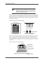
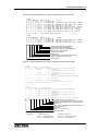
Information on Disposal of Old Electrical and Electronic Equipment and
Batteries (applicable for EU countries that have adopted separate waste
collection systems)
Products and batteries with the symbol (crossed-out
wheeled bin) cannot be disposed as household
waste. Old electrical and electronic equipment and
batteries should be recycled at a facility capable of
handling these items and their waste byproducts.
Contact your local authority for details in locating a
recycle facility nearest to you.
Proper recycling and waste disposal will help
conserve resources whilst preventing detrimental
effects on our health and the environment.
Notice: The sign “Pb” below the symbol for
batteries indicates that this battery contains lead.
Safety Summary
STOP
Warning! For your safety and the protection of the equipment, observe these
precautions when installing or servicing Zetron equipment:
• Follow all warnings and instructions marked on the equipment or included in documentation.
• Only technically qualified service personnel are permitted to install or service the equipment.
• Be aware of and avoid contact with areas subject to high voltage or amperage. Because some components can store
dangerous charges even after power is disconnected, always discharge components before touching.
• Never insert objects of any kind through openings in the equipment. Conductive foreign objects could produce a short
circuit that could cause fire, electrical shock, or equipment damage.
• Remove rings, watches, and other metallic objects from your body before opening equipment. These could be
electrical shock or burn hazards.
• Ensure that a proper electrostatic discharge device is used, to prevent damage to electronic components.
• Do not attempt internal service of equipment unless another person, capable of rendering aid and resuscitation, is
present.
• Do not work near rotating fans unless absolutely necessary. Exercise caution to prevent fans from taking in foreign
objects, including hair, clothing, and loose objects.
• Use care when moving equipment, especially rack-mounted modules, which could become unstable. Certain items
may be heavy. Use proper care when lifting.
3
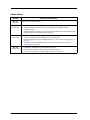
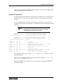
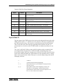
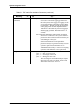
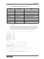
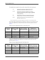
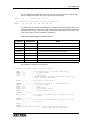
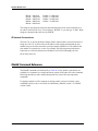
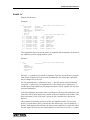
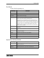
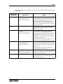
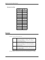
Release History
Release
Rev X.1
Enhancements/Changes
Last release in MS Word format.
Mar 2007
Rev Y
04 Jan 2008
4
• Document converted to FrameMaker® format.
• Material updated to support the release of the ZbaseW and ZlinkW database
maintenance tools.
• Added installation instructions for connecting the optional Digi One™ SP module to the
paging terminal local programming port (page 43)
Rev Z
24 Oct 2008
• Added material to Table 31 on page 227 to cover the fact that the Block Service codes
can now be applied to End-to-End lines as well as trunk lines.
• Added a description of the new OPARAM code for “2-tone format inter-page delay” on
page 229
• Added the command “MTTMk7VorD” to the section on the options.cus file. See
MTTMk7VorD on page 270.
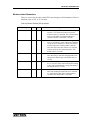
Rev AA
09 Mar 2009
• Updated the description for Overdial DID on page 223
• Updated the description of Telco Line Parameters on page 224
• Corrected the descriptions for JP5 and JP6 in Table 11 on page 107
025-9035AA
Contents
Contents
Introduction and Specifications . . . . . . . . . . . . . . . . . . . . . . . . . . . . . . . . . . . . . 13
Purpose of This Manual . . . . . . . . . . . . . . . . . . . . . . . . . . . . . . . . . . . . . . . . . . . . . . . . . . . . . . . .
Contents of This Manual . . . . . . . . . . . . . . . . . . . . . . . . . . . . . . . . . . . . . . . . . . . . . . . . . . . . . . .
System Specifications . . . . . . . . . . . . . . . . . . . . . . . . . . . . . . . . . . . . . . . . . . . . . . . . . . . . . . . . .
Model 2100 . . . . . . . . . . . . . . . . . . . . . . . . . . . . . . . . . . . . . . . . . . . . . . . . . . . . . . . . . . . . . .
Model 2200 . . . . . . . . . . . . . . . . . . . . . . . . . . . . . . . . . . . . . . . . . . . . . . . . . . . . . . . . . . . . . .
Model 2200EX . . . . . . . . . . . . . . . . . . . . . . . . . . . . . . . . . . . . . . . . . . . . . . . . . . . . . . . . . . . .
Lightning Protection . . . . . . . . . . . . . . . . . . . . . . . . . . . . . . . . . . . . . . . . . . . . . . . . . . . . . . . .
Operating Power . . . . . . . . . . . . . . . . . . . . . . . . . . . . . . . . . . . . . . . . . . . . . . . . . . . . . . . . . .
Trunk Card Specifications (702-9037 and 702-9117) . . . . . . . . . . . . . . . . . . . . . . . . . . . . . . . . .
DID Selector Level/PABX Trunk Configuration . . . . . . . . . . . . . . . . . . . . . . . . . . . . . . . . . . .
End-to-End/PABX Extension Configuration . . . . . . . . . . . . . . . . . . . . . . . . . . . . . . . . . . . . . .
PABX E&M Type I Configuration . . . . . . . . . . . . . . . . . . . . . . . . . . . . . . . . . . . . . . . . . . . . . .
Operator Local Phone Configuration . . . . . . . . . . . . . . . . . . . . . . . . . . . . . . . . . . . . . . . . . . .
Digital T1 Interface . . . . . . . . . . . . . . . . . . . . . . . . . . . . . . . . . . . . . . . . . . . . . . . . . . . . . . . . . . .
Multi-Port Card Specifications (702-9191) . . . . . . . . . . . . . . . . . . . . . . . . . . . . . . . . . . . . . . . . . .
Station Card Specifications (702-9038) . . . . . . . . . . . . . . . . . . . . . . . . . . . . . . . . . . . . . . . . . . . .
General Specifications . . . . . . . . . . . . . . . . . . . . . . . . . . . . . . . . . . . . . . . . . . . . . . . . . . . . . .
Electrical Specifications . . . . . . . . . . . . . . . . . . . . . . . . . . . . . . . . . . . . . . . . . . . . . . . . . . . . .
Voice System Specifications . . . . . . . . . . . . . . . . . . . . . . . . . . . . . . . . . . . . . . . . . . . . . . . . . . . .
ITU ADPCM Voice System (950-0385 or 950-0386) . . . . . . . . . . . . . . . . . . . . . . . . . . . . . . .
ADPCM Voice System (950-9061). . . . . . . . . . . . . . . . . . . . . . . . . . . . . . . . . . . . . . . . . . . . .
13
14
16
16
16
17
17
17
18
19
19
19
20
20
21
21
21
22
23
23
24
System Installation. . . . . . . . . . . . . . . . . . . . . . . . . . . . . . . . . . . . . . . . . . . . . . . . 25
Overview . . . . . . . . . . . . . . . . . . . . . . . . . . . . . . . . . . . . . . . . . . . . . . . . . . . . . . . . . . . . . . . . . . .
Installation Checklist . . . . . . . . . . . . . . . . . . . . . . . . . . . . . . . . . . . . . . . . . . . . . . . . . . . . . . . . . .
Alignment Procedure . . . . . . . . . . . . . . . . . . . . . . . . . . . . . . . . . . . . . . . . . . . . . . . . . . . . . . . . . .
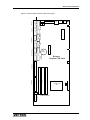
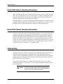
Hard Disk Card Mounting Information . . . . . . . . . . . . . . . . . . . . . . . . . . . . . . . . . . . . . . . . . . . . .
SCSI Disk Card Mounting Information (M2200) . . . . . . . . . . . . . . . . . . . . . . . . . . . . . . . . . . . . .
TELCO Ground Reference . . . . . . . . . . . . . . . . . . . . . . . . . . . . . . . . . . . . . . . . . . . . . . . . . . . . .
48 Vdc Ground Jumper . . . . . . . . . . . . . . . . . . . . . . . . . . . . . . . . . . . . . . . . . . . . . . . . . . . . .
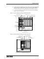
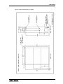
Model 2200 Cabinet Mounting Information . . . . . . . . . . . . . . . . . . . . . . . . . . . . . . . . . . . . . . . . .
Model 2100 Cabinet Mounting Information . . . . . . . . . . . . . . . . . . . . . . . . . . . . . . . . . . . . . . . . .
Cable Routing . . . . . . . . . . . . . . . . . . . . . . . . . . . . . . . . . . . . . . . . . . . . . . . . . . . . . . . . . . . . . . .
Model 2200EX Installation . . . . . . . . . . . . . . . . . . . . . . . . . . . . . . . . . . . . . . . . . . . . . . . . . . . . . .
General . . . . . . . . . . . . . . . . . . . . . . . . . . . . . . . . . . . . . . . . . . . . . . . . . . . . . . . . . . . . . . . . .
Model 2200EX Setup . . . . . . . . . . . . . . . . . . . . . . . . . . . . . . . . . . . . . . . . . . . . . . . . . . . . . . .
25
26
30
32
32
33
33
36
36
36
39
39
40
5
Contents
Model 2200 Main Chassis Setup . . . . . . . . . . . . . . . . . . . . . . . . . . . . . . . . . . . . . . . . . . . . .
Power Up Test . . . . . . . . . . . . . . . . . . . . . . . . . . . . . . . . . . . . . . . . . . . . . . . . . . . . . . . . . . .
2000 Series Printer Option . . . . . . . . . . . . . . . . . . . . . . . . . . . . . . . . . . . . . . . . . . . . . . . . . . . . .
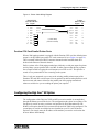
ZCPU Serial Printer Port . . . . . . . . . . . . . . . . . . . . . . . . . . . . . . . . . . . . . . . . . . . . . . . . . . .
Pentium CPU Card Parallel Printer Ports . . . . . . . . . . . . . . . . . . . . . . . . . . . . . . . . . . . . . . .
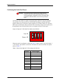
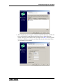
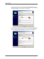
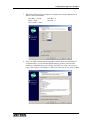
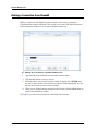
Configuring the Digi One™ SP Option . . . . . . . . . . . . . . . . . . . . . . . . . . . . . . . . . . . . . . . . . . . .
Confirming the Serial Port Pinout . . . . . . . . . . . . . . . . . . . . . . . . . . . . . . . . . . . . . . . . . . . . .
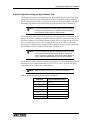
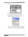
Initial Configuration Using the Digi Software Tool. . . . . . . . . . . . . . . . . . . . . . . . . . . . . . . . .
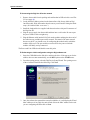
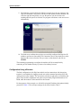
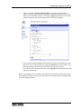
Configuration Using a Browser . . . . . . . . . . . . . . . . . . . . . . . . . . . . . . . . . . . . . . . . . . . . . . .
41
41
42
42
43
43
44
45
50
Installing the Office Software . . . . . . . . . . . . . . . . . . . . . . . . . . . . . . . . . . . . . . . . 55
Overview . . . . . . . . . . . . . . . . . . . . . . . . . . . . . . . . . . . . . . . . . . . . . . . . . . . . . . . . . . . . . . . . . .
Office Computer Specification Guidelines . . . . . . . . . . . . . . . . . . . . . . . . . . . . . . . . . . . . . . . . .
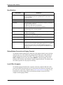
Specifications . . . . . . . . . . . . . . . . . . . . . . . . . . . . . . . . . . . . . . . . . . . . . . . . . . . . . . . . . . . .
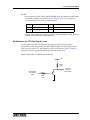
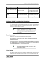
Dialup Modem Connection to Paging Terminal . . . . . . . . . . . . . . . . . . . . . . . . . . . . . . . . . .
Local Office Computer . . . . . . . . . . . . . . . . . . . . . . . . . . . . . . . . . . . . . . . . . . . . . . . . . . . . .
Installing Office Software . . . . . . . . . . . . . . . . . . . . . . . . . . . . . . . . . . . . . . . . . . . . . . . . . . . . . .
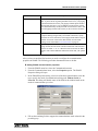
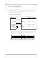
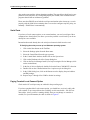
Installing ZbaseW for Multiple Users on a Network . . . . . . . . . . . . . . . . . . . . . . . . . . . . . . . . . .
Installing ZbaseW on the First PC . . . . . . . . . . . . . . . . . . . . . . . . . . . . . . . . . . . . . . . . . . . .
Installing ZbaseW on Subsequent PCs . . . . . . . . . . . . . . . . . . . . . . . . . . . . . . . . . . . . . . . .
Starting ZbaseW . . . . . . . . . . . . . . . . . . . . . . . . . . . . . . . . . . . . . . . . . . . . . . . . . . . . . . . . . . . . .
ZbaseW Communications (ZlinkW) . . . . . . . . . . . . . . . . . . . . . . . . . . . . . . . . . . . . . . . . . . . . . .
ZlinkW Property Fields . . . . . . . . . . . . . . . . . . . . . . . . . . . . . . . . . . . . . . . . . . . . . . . . . . . . .
Modem Connections. . . . . . . . . . . . . . . . . . . . . . . . . . . . . . . . . . . . . . . . . . . . . . . . . . . . . . .
Local Connections . . . . . . . . . . . . . . . . . . . . . . . . . . . . . . . . . . . . . . . . . . . . . . . . . . . . . . . .
Network Connections . . . . . . . . . . . . . . . . . . . . . . . . . . . . . . . . . . . . . . . . . . . . . . . . . . . . . .
Exiting ZbaseW . . . . . . . . . . . . . . . . . . . . . . . . . . . . . . . . . . . . . . . . . . . . . . . . . . . . . . . . . . . . .
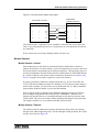
Backups . . . . . . . . . . . . . . . . . . . . . . . . . . . . . . . . . . . . . . . . . . . . . . . . . . . . . . . . . . . . . . . . . . .
Changing ZlinkW Passwords . . . . . . . . . . . . . . . . . . . . . . . . . . . . . . . . . . . . . . . . . . . . . . . .
Office Computer Operations Guidelines . . . . . . . . . . . . . . . . . . . . . . . . . . . . . . . . . . . . . . . . . .
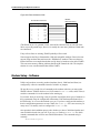
Shared PC . . . . . . . . . . . . . . . . . . . . . . . . . . . . . . . . . . . . . . . . . . . . . . . . . . . . . . . . . . . . . .
Linking to the Paging Terminal . . . . . . . . . . . . . . . . . . . . . . . . . . . . . . . . . . . . . . . . . . . . . . .
Database Operations . . . . . . . . . . . . . . . . . . . . . . . . . . . . . . . . . . . . . . . . . . . . . . . . . . . . . .
Training and Classes . . . . . . . . . . . . . . . . . . . . . . . . . . . . . . . . . . . . . . . . . . . . . . . . . . . . . .
55
55
56
56
56
57
57
58
59
59
60
62
63
64
64
64
65
65
66
66
66
69
69
Trunk Cards and Connections . . . . . . . . . . . . . . . . . . . . . . . . . . . . . . . . . . . . . . . 71
Selecting a Phone Line . . . . . . . . . . . . . . . . . . . . . . . . . . . . . . . . . . . . . . . . . . . . . . . . . . . . . . .
Support for T1 Trunks . . . . . . . . . . . . . . . . . . . . . . . . . . . . . . . . . . . . . . . . . . . . . . . . . . . . . . . .
TELCO Connectors . . . . . . . . . . . . . . . . . . . . . . . . . . . . . . . . . . . . . . . . . . . . . . . . . . . . . . . . . .
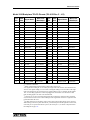
Model 2100 Backplane TELCO Pinouts (702-9133 Rev C - J13). . . . . . . . . . . . . . . . . . . . .
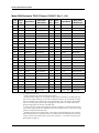
Model 2200 Backplane TELCO Pinouts (702-9071 Rev C - J19). . . . . . . . . . . . . . . . . . . . .
Model 2200 Backplane TELCO Pinouts (702-9071 Rev C - J20). . . . . . . . . . . . . . . . . . . . .
Model 2200 Main and Expansion Chassis Backplane Pinouts (702-9071 Rev E - J23) . . .
Adjustment Procedures . . . . . . . . . . . . . . . . . . . . . . . . . . . . . . . . . . . . . . . . . . . . . . . . . . . . . . .
Trunk Cards (702-9037 and 702-9117) . . . . . . . . . . . . . . . . . . . . . . . . . . . . . . . . . . . . . . . .
To Tel Adjustment . . . . . . . . . . . . . . . . . . . . . . . . . . . . . . . . . . . . . . . . . . . . . . . . . . . . . . . . .
From Tel Adjustment. . . . . . . . . . . . . . . . . . . . . . . . . . . . . . . . . . . . . . . . . . . . . . . . . . . . . . .
Hybrid Adjustment . . . . . . . . . . . . . . . . . . . . . . . . . . . . . . . . . . . . . . . . . . . . . . . . . . . . . . . .
Dial Click Card . . . . . . . . . . . . . . . . . . . . . . . . . . . . . . . . . . . . . . . . . . . . . . . . . . . . . . . . . . .
MF Decoder Option . . . . . . . . . . . . . . . . . . . . . . . . . . . . . . . . . . . . . . . . . . . . . . . . . . . . . . .
Alarm Option. . . . . . . . . . . . . . . . . . . . . . . . . . . . . . . . . . . . . . . . . . . . . . . . . . . . . . . . . . . . .
6
71
71
72
73
74
75
76
77
77
77
77
78
82
83
83
025-9035AA
Contents
Large RAM . . . . . . . . . . . . . . . . . . . . . . . . . . . . . . . . . . . . . . . . . . . . . . . . . . . . . . . . . . . . . . .
4-Wire Audio E&M . . . . . . . . . . . . . . . . . . . . . . . . . . . . . . . . . . . . . . . . . . . . . . . . . . . . . . . . .
Audio Daughter Board (4-wire audio E&M) Rev B . . . . . . . . . . . . . . . . . . . . . . . . . . . . . . . . .
Configuring Trunk Cards (702-9037 and 702-9117) . . . . . . . . . . . . . . . . . . . . . . . . . . . . . . . . . .
Trunk Card Removal/Installation . . . . . . . . . . . . . . . . . . . . . . . . . . . . . . . . . . . . . . . . . . . . . .
Switch Settings. . . . . . . . . . . . . . . . . . . . . . . . . . . . . . . . . . . . . . . . . . . . . . . . . . . . . . . . . . . .
Jumper Matrix Settings . . . . . . . . . . . . . . . . . . . . . . . . . . . . . . . . . . . . . . . . . . . . . . . . . . . . .
Configuring for DID Operation . . . . . . . . . . . . . . . . . . . . . . . . . . . . . . . . . . . . . . . . . . . . . . . . . . .
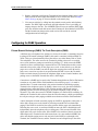
Central Office (C.O.) DID Description . . . . . . . . . . . . . . . . . . . . . . . . . . . . . . . . . . . . . . . . . .
DID Installation. . . . . . . . . . . . . . . . . . . . . . . . . . . . . . . . . . . . . . . . . . . . . . . . . . . . . . . . . . . .
Operator Local Station . . . . . . . . . . . . . . . . . . . . . . . . . . . . . . . . . . . . . . . . . . . . . . . . . . . . . . . . .
Configuring for End-to-End Loop Start Operation . . . . . . . . . . . . . . . . . . . . . . . . . . . . . . . . . . . .
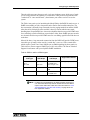
End-to-End Loop Start/PABX Station Description . . . . . . . . . . . . . . . . . . . . . . . . . . . . . . . . .
End-to-End Installation. . . . . . . . . . . . . . . . . . . . . . . . . . . . . . . . . . . . . . . . . . . . . . . . . . . . . .
Configuring for PABX Operation . . . . . . . . . . . . . . . . . . . . . . . . . . . . . . . . . . . . . . . . . . . . . . . . .
Private Branch Exchange (PABX) Tie-Trunk Description (E&M) . . . . . . . . . . . . . . . . . . . . . .
Private Branch Exchange (PABX) Ground Start Description (GS) . . . . . . . . . . . . . . . . . . . . .
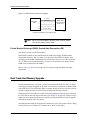
Dual Trunk Card Memory Upgrade . . . . . . . . . . . . . . . . . . . . . . . . . . . . . . . . . . . . . . . . . . . . . . .
84
84
85
86
86
87
87
90
90
90
91
91
91
91
92
92
94
94
Radio System . . . . . . . . . . . . . . . . . . . . . . . . . . . . . . . . . . . . . . . . . . . . . . . . . . . . 97
Overview . . . . . . . . . . . . . . . . . . . . . . . . . . . . . . . . . . . . . . . . . . . . . . . . . . . . . . . . . . . . . . . . . . . 97
General System Design . . . . . . . . . . . . . . . . . . . . . . . . . . . . . . . . . . . . . . . . . . . . . . . . . . . . . . . . 97
Radio Connectors . . . . . . . . . . . . . . . . . . . . . . . . . . . . . . . . . . . . . . . . . . . . . . . . . . . . . . . . . . . . 98
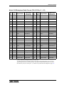
Model 2100 Backplane Radio Pinouts (702-9133 Rev C - J13). . . . . . . . . . . . . . . . . . . . . . . 99
Model 2100 Backplane Radio Pinouts (702-9133 Rev C - J14). . . . . . . . . . . . . . . . . . . . . . 100
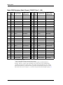
Model 2200 Backplane Radio Pinouts (702-9071 Rev C - J19). . . . . . . . . . . . . . . . . . . . . . 101
Model 2200 Backplane Radio Pinouts (702-9071 Rev C - J20). . . . . . . . . . . . . . . . . . . . . . 102
Model 2200 Backplane Radio Pinouts (702-9071 Rev C - J21). . . . . . . . . . . . . . . . . . . . . . 103
Model 2200 Backplane Radio Pinouts (702-9071 Rev C - J22). . . . . . . . . . . . . . . . . . . . . . 104
Station Card Removal/Installation . . . . . . . . . . . . . . . . . . . . . . . . . . . . . . . . . . . . . . . . . . . . . . . 105
Switch Settings. . . . . . . . . . . . . . . . . . . . . . . . . . . . . . . . . . . . . . . . . . . . . . . . . . . . . . . . . . . 105
Jumper Settings . . . . . . . . . . . . . . . . . . . . . . . . . . . . . . . . . . . . . . . . . . . . . . . . . . . . . . . . . . 106
Station Card Adjustments. . . . . . . . . . . . . . . . . . . . . . . . . . . . . . . . . . . . . . . . . . . . . . . . . . . 107
Radio Signal Descriptions . . . . . . . . . . . . . . . . . . . . . . . . . . . . . . . . . . . . . . . . . . . . . . . . . . . . . 109
Co-located Radio Station . . . . . . . . . . . . . . . . . . . . . . . . . . . . . . . . . . . . . . . . . . . . . . . . . . . . . . 110
Modifications for TTL Data Signal Levels. . . . . . . . . . . . . . . . . . . . . . . . . . . . . . . . . . . . . . . 111
Co-located Motorola PURC Station . . . . . . . . . . . . . . . . . . . . . . . . . . . . . . . . . . . . . . . . . . . . . . 112
Remote Control Options (950-9074 and 950-9111) . . . . . . . . . . . . . . . . . . . . . . . . . . . . . . . . . . 113
Zetron Model 66 Transmitter Control Panel . . . . . . . . . . . . . . . . . . . . . . . . . . . . . . . . . . . . . 114
Motorola PSC/SSC/DDC Controller . . . . . . . . . . . . . . . . . . . . . . . . . . . . . . . . . . . . . . . . . . . 115
Motorola ASC (Advanced Simulcast Controller) . . . . . . . . . . . . . . . . . . . . . . . . . . . . . . . . . 116
TX Link Controllers. . . . . . . . . . . . . . . . . . . . . . . . . . . . . . . . . . . . . . . . . . . . . . . . . . . . . . . . 117
Quintron 1000 Exciter Hookup . . . . . . . . . . . . . . . . . . . . . . . . . . . . . . . . . . . . . . . . . . . . . . . 118
Connecting Zetron 2000 Series to Glenayre Transmitter. . . . . . . . . . . . . . . . . . . . . . . . . . . 118
Multiport Serial TAP Input . . . . . . . . . . . . . . . . . . . . . . . . . . . . . . . . . . . . . . . . . . 119
Overview . . . . . . . . . . . . . . . . . . . . . . . . . . . . . . . . . . . . . . . . . . . . . . . . . . . . . . . . . . . . . . . . . .
Paging Terminal Requirements for the Multiport Card . . . . . . . . . . . . . . . . . . . . . . . . . . . . .
General Information . . . . . . . . . . . . . . . . . . . . . . . . . . . . . . . . . . . . . . . . . . . . . . . . . . . . . . .
Option Details . . . . . . . . . . . . . . . . . . . . . . . . . . . . . . . . . . . . . . . . . . . . . . . . . . . . . . . . . . . . . .
ZbaseW . . . . . . . . . . . . . . . . . . . . . . . . . . . . . . . . . . . . . . . . . . . . . . . . . . . . . . . . . . . . . . . . . . .
119
119
119
120
120
7
Contents
Installation and Configuration . . . . . . . . . . . . . . . . . . . . . . . . . . . . . . . . . . . . . . . . . . . . . . . . . .
General. . . . . . . . . . . . . . . . . . . . . . . . . . . . . . . . . . . . . . . . . . . . . . . . . . . . . . . . . . . . . . . .
Information Needed . . . . . . . . . . . . . . . . . . . . . . . . . . . . . . . . . . . . . . . . . . . . . . . . . . . . . .
Hardware Installation . . . . . . . . . . . . . . . . . . . . . . . . . . . . . . . . . . . . . . . . . . . . . . . . . . . . .
Connections . . . . . . . . . . . . . . . . . . . . . . . . . . . . . . . . . . . . . . . . . . . . . . . . . . . . . . . . . . . .
Miscellaneous. . . . . . . . . . . . . . . . . . . . . . . . . . . . . . . . . . . . . . . . . . . . . . . . . . . . . . . . . . .
Software Configuration . . . . . . . . . . . . . . . . . . . . . . . . . . . . . . . . . . . . . . . . . . . . . . . . . . . .
Multiport Configurations . . . . . . . . . . . . . . . . . . . . . . . . . . . . . . . . . . . . . . . . . . . . . . . . . . .
Connecting Multiport Hardware to RS-232 Connectors . . . . . . . . . . . . . . . . . . . . . . . . . . .
UDS 202T Modem Hookup Example . . . . . . . . . . . . . . . . . . . . . . . . . . . . . . . . . . . . . . . . .
Pinout for the Siemon S66M Punchdown Block . . . . . . . . . . . . . . . . . . . . . . . . . . . . . . . . .
Multiport Wire List . . . . . . . . . . . . . . . . . . . . . . . . . . . . . . . . . . . . . . . . . . . . . . . . . . . . . . . .
Octal RS-232 Cable Used with the Multiport Card . . . . . . . . . . . . . . . . . . . . . . . . . . . . . . .
121
121
121
121
122
122
123
124
124
128
129
130
131
Multiport for TNPP and TAP Outdial. . . . . . . . . . . . . . . . . . . . . . . . . . . . . . . . . . 133
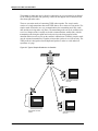
TNPP Overview . . . . . . . . . . . . . . . . . . . . . . . . . . . . . . . . . . . . . . . . . . . . . . . . . . . . . . . . . . . .
TNPP Details . . . . . . . . . . . . . . . . . . . . . . . . . . . . . . . . . . . . . . . . . . . . . . . . . . . . . . . . . . . . . .
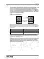
Types of Packets . . . . . . . . . . . . . . . . . . . . . . . . . . . . . . . . . . . . . . . . . . . . . . . . . . . . . . . .
Types of Links. . . . . . . . . . . . . . . . . . . . . . . . . . . . . . . . . . . . . . . . . . . . . . . . . . . . . . . . . . .
TNPP Limitations and Specifications . . . . . . . . . . . . . . . . . . . . . . . . . . . . . . . . . . . . . . . . . . . .
Limitations of TNPP . . . . . . . . . . . . . . . . . . . . . . . . . . . . . . . . . . . . . . . . . . . . . . . . . . . . . .
Our Current TNPP Limitations . . . . . . . . . . . . . . . . . . . . . . . . . . . . . . . . . . . . . . . . . . . . . .
Limitations of Multi-node TNPP . . . . . . . . . . . . . . . . . . . . . . . . . . . . . . . . . . . . . . . . . . . . .
Items Supplied for this Configuration . . . . . . . . . . . . . . . . . . . . . . . . . . . . . . . . . . . . . . . . .
Port Configuration. . . . . . . . . . . . . . . . . . . . . . . . . . . . . . . . . . . . . . . . . . . . . . . . . . . . . . . .
Using TNPP with ZbaseW v310 and Zpage v310 . . . . . . . . . . . . . . . . . . . . . . . . . . . . . . .
Network CUS Parameter File . . . . . . . . . . . . . . . . . . . . . . . . . . . . . . . . . . . . . . . . . . . . . . .
Configuration - TNPP Addresses . . . . . . . . . . . . . . . . . . . . . . . . . . . . . . . . . . . . . . . . . . . .
Software Configuration . . . . . . . . . . . . . . . . . . . . . . . . . . . . . . . . . . . . . . . . . . . . . . . . . . . .
Limitations of Single-node TNPP (Older Systems). . . . . . . . . . . . . . . . . . . . . . . . . . . . . . .
Format of TNPP Related Log File Postings . . . . . . . . . . . . . . . . . . . . . . . . . . . . . . . . . . . . . . .
TNPP Link Tips - UDS 202T and Leased Line . . . . . . . . . . . . . . . . . . . . . . . . . . . . . . . . . . . . .
TAP Outdial . . . . . . . . . . . . . . . . . . . . . . . . . . . . . . . . . . . . . . . . . . . . . . . . . . . . . . . . . . . . . . .
Modem Related Information . . . . . . . . . . . . . . . . . . . . . . . . . . . . . . . . . . . . . . . . . . . . . . . .
OPARAM CDS Settings . . . . . . . . . . . . . . . . . . . . . . . . . . . . . . . . . . . . . . . . . . . . . . . . . . .
NETWORK.CUS Settings. . . . . . . . . . . . . . . . . . . . . . . . . . . . . . . . . . . . . . . . . . . . . . . . . .
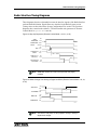
TAP Outdial Processing . . . . . . . . . . . . . . . . . . . . . . . . . . . . . . . . . . . . . . . . . . . . . . . . . . .
TAP Outdial Status . . . . . . . . . . . . . . . . . . . . . . . . . . . . . . . . . . . . . . . . . . . . . . . . . . . . . . .
133
133
136
136
137
137
137
137
138
138
139
140
140
141
141
142
144
146
146
147
147
148
148
Theory of Operation. . . . . . . . . . . . . . . . . . . . . . . . . . . . . . . . . . . . . . . . . . . . . . . 149
Overview . . . . . . . . . . . . . . . . . . . . . . . . . . . . . . . . . . . . . . . . . . . . . . . . . . . . . . . . . . . . . . . . .
System Startup . . . . . . . . . . . . . . . . . . . . . . . . . . . . . . . . . . . . . . . . . . . . . . . . . . . . . . . . . . . . .
System Operation . . . . . . . . . . . . . . . . . . . . . . . . . . . . . . . . . . . . . . . . . . . . . . . . . . . . . . . . . .
CPU Indicators . . . . . . . . . . . . . . . . . . . . . . . . . . . . . . . . . . . . . . . . . . . . . . . . . . . . . . . . . .
Idle . . . . . . . . . . . . . . . . . . . . . . . . . . . . . . . . . . . . . . . . . . . . . . . . . . . . . . . . . . . . . . . . . . .
Call Processing. . . . . . . . . . . . . . . . . . . . . . . . . . . . . . . . . . . . . . . . . . . . . . . . . . . . . . . . . .
CPU Card (702-9176) . . . . . . . . . . . . . . . . . . . . . . . . . . . . . . . . . . . . . . . . . . . . . . . . . . . . . . .
Modem Card (802-0041) . . . . . . . . . . . . . . . . . . . . . . . . . . . . . . . . . . . . . . . . . . . . . . . . . . . . .
SCSI . . . . . . . . . . . . . . . . . . . . . . . . . . . . . . . . . . . . . . . . . . . . . . . . . . . . . . . . . . . . . . . . . . . . .
2200EX . . . . . . . . . . . . . . . . . . . . . . . . . . . . . . . . . . . . . . . . . . . . . . . . . . . . . . . . . . . . . . . . . .
Dual Trunk Card (702-9117) Rev D and Later . . . . . . . . . . . . . . . . . . . . . . . . . . . . . . . . . . . . .
8
149
149
150
150
150
151
151
153
153
154
154
025-9035AA
Contents
Dual Trunk Card — 4-Wire E&M (702-9318) . . . . . . . . . . . . . . . . . . . . . . . . . . . . . . . . . . . . . . .
Multiport Serial Card (702-9191) . . . . . . . . . . . . . . . . . . . . . . . . . . . . . . . . . . . . . . . . . . . . . . . .
Dual Dial Click Option (for 702-9117) . . . . . . . . . . . . . . . . . . . . . . . . . . . . . . . . . . . . . . . . . . . .
MF Decoder Option . . . . . . . . . . . . . . . . . . . . . . . . . . . . . . . . . . . . . . . . . . . . . . . . . . . . . . . . . .
Station Card . . . . . . . . . . . . . . . . . . . . . . . . . . . . . . . . . . . . . . . . . . . . . . . . . . . . . . . . . . . . . . . .
Station Card II (702-9441) . . . . . . . . . . . . . . . . . . . . . . . . . . . . . . . . . . . . . . . . . . . . . . . . . .
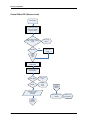
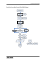
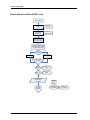
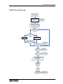
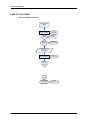
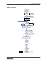
Call Processing Flow Charts . . . . . . . . . . . . . . . . . . . . . . . . . . . . . . . . . . . . . . . . . . . . . . . . . . .
Central Office DID (Selector Level) . . . . . . . . . . . . . . . . . . . . . . . . . . . . . . . . . . . . . . . . . . .
End-to-End Loop Start (Central Office/PABX Station) . . . . . . . . . . . . . . . . . . . . . . . . . . . . .
End-to-End Ground Start (PABX Trunk). . . . . . . . . . . . . . . . . . . . . . . . . . . . . . . . . . . . . . . .
PABX Trunk (Tip-Ring Loop) . . . . . . . . . . . . . . . . . . . . . . . . . . . . . . . . . . . . . . . . . . . . . . . .
PABX Tie-Trunk (E&M). . . . . . . . . . . . . . . . . . . . . . . . . . . . . . . . . . . . . . . . . . . . . . . . . . . . .
Operator Local Phone . . . . . . . . . . . . . . . . . . . . . . . . . . . . . . . . . . . . . . . . . . . . . . . . . . . . .
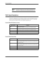
TELCO Signal Descriptions . . . . . . . . . . . . . . . . . . . . . . . . . . . . . . . . . . . . . . . . . . . . . . . . . . . .
Central Office DID (Selector Level) . . . . . . . . . . . . . . . . . . . . . . . . . . . . . . . . . . . . . . . . . . .
Central Office End-to-End . . . . . . . . . . . . . . . . . . . . . . . . . . . . . . . . . . . . . . . . . . . . . . . . . .
PABX E&M Type I Tie-Trunk (2-wire audio) . . . . . . . . . . . . . . . . . . . . . . . . . . . . . . . . . . . . .
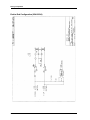
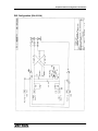
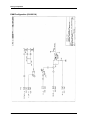
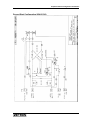
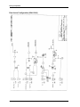
Simplified TELCO Configuration Schematics . . . . . . . . . . . . . . . . . . . . . . . . . . . . . . . . . . . . . .
End-to-End Configuration (024-0009A) . . . . . . . . . . . . . . . . . . . . . . . . . . . . . . . . . . . . . . . .
DID Configuration (024-0010A) . . . . . . . . . . . . . . . . . . . . . . . . . . . . . . . . . . . . . . . . . . . . . .
E&M Configuration (024-0011A) . . . . . . . . . . . . . . . . . . . . . . . . . . . . . . . . . . . . . . . . . . . . .
Ground Start Configuration (024-0012A) . . . . . . . . . . . . . . . . . . . . . . . . . . . . . . . . . . . . . . .
Dual 4-wire Configuration (024-0100A) . . . . . . . . . . . . . . . . . . . . . . . . . . . . . . . . . . . . . . . .
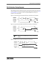
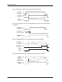
TELCO Interface Timing Diagrams . . . . . . . . . . . . . . . . . . . . . . . . . . . . . . . . . . . . . . . . . . . . . .
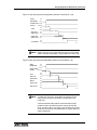
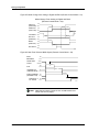
Radio Interface Timing Diagrams . . . . . . . . . . . . . . . . . . . . . . . . . . . . . . . . . . . . . . . . . . . . . . .
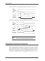
Timing Diagrams for External TX Control Unit . . . . . . . . . . . . . . . . . . . . . . . . . . . . . . . . . . . . . .
156
156
157
158
158
158
159
160
161
162
163
164
165
166
166
166
167
167
168
169
170
171
172
173
175
176
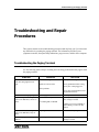
Troubleshooting and Repair Procedures . . . . . . . . . . . . . . . . . . . . . . . . . . . . . 179
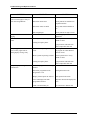
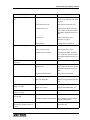
Troubleshooting the Paging Terminal . . . . . . . . . . . . . . . . . . . . . . . . . . . . . . . . . . . . . . . . . . . .
Swapping Cards. . . . . . . . . . . . . . . . . . . . . . . . . . . . . . . . . . . . . . . . . . . . . . . . . . . . . . . . . .
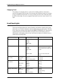
Front Panel Lights . . . . . . . . . . . . . . . . . . . . . . . . . . . . . . . . . . . . . . . . . . . . . . . . . . . . . . . . . . .
Progress Tones . . . . . . . . . . . . . . . . . . . . . . . . . . . . . . . . . . . . . . . . . . . . . . . . . . . . . . . . . . . . .
DIP Switches and Matrix Plugs . . . . . . . . . . . . . . . . . . . . . . . . . . . . . . . . . . . . . . . . . . . . . . . . .
Recommended Maintenance . . . . . . . . . . . . . . . . . . . . . . . . . . . . . . . . . . . . . . . . . . . . . . . . . . .
Troubleshooting the Office Computer . . . . . . . . . . . . . . . . . . . . . . . . . . . . . . . . . . . . . . . . . . . .
Additional ZlinkW Troubleshooting Information . . . . . . . . . . . . . . . . . . . . . . . . . . . . . . . . . . . . .
General Information . . . . . . . . . . . . . . . . . . . . . . . . . . . . . . . . . . . . . . . . . . . . . . . . . . . . . . .
Office Computer . . . . . . . . . . . . . . . . . . . . . . . . . . . . . . . . . . . . . . . . . . . . . . . . . . . . . . . . . .
Serial Ports. . . . . . . . . . . . . . . . . . . . . . . . . . . . . . . . . . . . . . . . . . . . . . . . . . . . . . . . . . . . . .
Paging Terminal Local Connect Option . . . . . . . . . . . . . . . . . . . . . . . . . . . . . . . . . . . . . . . .
Modem Connect. . . . . . . . . . . . . . . . . . . . . . . . . . . . . . . . . . . . . . . . . . . . . . . . . . . . . . . . . .
Modem Setup - Software . . . . . . . . . . . . . . . . . . . . . . . . . . . . . . . . . . . . . . . . . . . . . . . . . . . . . .
Connections . . . . . . . . . . . . . . . . . . . . . . . . . . . . . . . . . . . . . . . . . . . . . . . . . . . . . . . . . . . . . . . .
Local Connect . . . . . . . . . . . . . . . . . . . . . . . . . . . . . . . . . . . . . . . . . . . . . . . . . . . . . . . . . . .
Phone Line Connect. . . . . . . . . . . . . . . . . . . . . . . . . . . . . . . . . . . . . . . . . . . . . . . . . . . . . . .
ZbaseW Setup . . . . . . . . . . . . . . . . . . . . . . . . . . . . . . . . . . . . . . . . . . . . . . . . . . . . . . . . . . . . . .
Running ZlinkW . . . . . . . . . . . . . . . . . . . . . . . . . . . . . . . . . . . . . . . . . . . . . . . . . . . . . . . . . . . . .
Troubleshooting . . . . . . . . . . . . . . . . . . . . . . . . . . . . . . . . . . . . . . . . . . . . . . . . . . . . . . . . . . . . .
Garbage on Screen . . . . . . . . . . . . . . . . . . . . . . . . . . . . . . . . . . . . . . . . . . . . . . . . . . . . . . .
Check Terminal Modem . . . . . . . . . . . . . . . . . . . . . . . . . . . . . . . . . . . . . . . . . . . . . . . . . . . .
Check PC Modem . . . . . . . . . . . . . . . . . . . . . . . . . . . . . . . . . . . . . . . . . . . . . . . . . . . . . . . .
Other Checks . . . . . . . . . . . . . . . . . . . . . . . . . . . . . . . . . . . . . . . . . . . . . . . . . . . . . . . . . . . .
179
182
182
184
184
185
186
187
187
187
188
188
189
190
191
191
191
192
192
193
193
193
193
194
9
Contents
Machine/Environment . . . . . . . . . . . . . . . . . . . . . . . . . . . . . . . . . . . . . . . . . . . . . . . . . . . . . 194
Voice Storage System . . . . . . . . . . . . . . . . . . . . . . . . . . . . . . . . . . . . . . . . . . . . . 197
Overview . . . . . . . . . . . . . . . . . . . . . . . . . . . . . . . . . . . . . . . . . . . . . . . . . . . . . . . . . . . . . . . . .
ITU ADPCM Cards (702-0065 and 702-0066) . . . . . . . . . . . . . . . . . . . . . . . . . . . . . . . . . . . . .
Slots . . . . . . . . . . . . . . . . . . . . . . . . . . . . . . . . . . . . . . . . . . . . . . . . . . . . . . . . . . . . . . . . . .
Address Settings . . . . . . . . . . . . . . . . . . . . . . . . . . . . . . . . . . . . . . . . . . . . . . . . . . . . . . . .
Mode Settings (ITU ADPCM Cards 702-0065 and 702-0066) . . . . . . . . . . . . . . . . . . . . . .
Audio Level. . . . . . . . . . . . . . . . . . . . . . . . . . . . . . . . . . . . . . . . . . . . . . . . . . . . . . . . . . . . .
Test Pins (ADPCM Cards 702-0065 and 702-0066). . . . . . . . . . . . . . . . . . . . . . . . . . . . . .
“Old” ADPCM Card (702-9153) . . . . . . . . . . . . . . . . . . . . . . . . . . . . . . . . . . . . . . . . . . . . . . . .
Slots . . . . . . . . . . . . . . . . . . . . . . . . . . . . . . . . . . . . . . . . . . . . . . . . . . . . . . . . . . . . . . . . . .
Address Settings . . . . . . . . . . . . . . . . . . . . . . . . . . . . . . . . . . . . . . . . . . . . . . . . . . . . . . . .
Mode Settings (ADPCM Card 702-9153) . . . . . . . . . . . . . . . . . . . . . . . . . . . . . . . . . . . . . .
Audio Level. . . . . . . . . . . . . . . . . . . . . . . . . . . . . . . . . . . . . . . . . . . . . . . . . . . . . . . . . . . . .
Test Pins (ADPCM Card 702-9153) . . . . . . . . . . . . . . . . . . . . . . . . . . . . . . . . . . . . . . . . . .
Upgrades . . . . . . . . . . . . . . . . . . . . . . . . . . . . . . . . . . . . . . . . . . . . . . . . . . . . . . . . . . . . . . . . .
Installing New ICs in the Voice Card. . . . . . . . . . . . . . . . . . . . . . . . . . . . . . . . . . . . . . . . . .
Adding Second ADPCM Card . . . . . . . . . . . . . . . . . . . . . . . . . . . . . . . . . . . . . . . . . . . . . .
Operation . . . . . . . . . . . . . . . . . . . . . . . . . . . . . . . . . . . . . . . . . . . . . . . . . . . . . . . . . . . . . . . . .
Power Up . . . . . . . . . . . . . . . . . . . . . . . . . . . . . . . . . . . . . . . . . . . . . . . . . . . . . . . . . . . . . .
Record/Play . . . . . . . . . . . . . . . . . . . . . . . . . . . . . . . . . . . . . . . . . . . . . . . . . . . . . . . . . . . .
Silence Deletion . . . . . . . . . . . . . . . . . . . . . . . . . . . . . . . . . . . . . . . . . . . . . . . . . . . . . . . . .
Lights . . . . . . . . . . . . . . . . . . . . . . . . . . . . . . . . . . . . . . . . . . . . . . . . . . . . . . . . . . . . . . . . .
Maintenance . . . . . . . . . . . . . . . . . . . . . . . . . . . . . . . . . . . . . . . . . . . . . . . . . . . . . . . . . . . . . . .
Voice File Restore and Backup . . . . . . . . . . . . . . . . . . . . . . . . . . . . . . . . . . . . . . . . . . . . .
Single Files . . . . . . . . . . . . . . . . . . . . . . . . . . . . . . . . . . . . . . . . . . . . . . . . . . . . . . . . . . . . .
Client Prompts . . . . . . . . . . . . . . . . . . . . . . . . . . . . . . . . . . . . . . . . . . . . . . . . . . . . . . . . . .
Mirrored Drive Syncronizing (Obsolete) . . . . . . . . . . . . . . . . . . . . . . . . . . . . . . . . . . . . . . . . . .
RAID Hard Drive . . . . . . . . . . . . . . . . . . . . . . . . . . . . . . . . . . . . . . . . . . . . . . . . . . . . . . . . . . .
RAID Drive Option Installation (011-0662) . . . . . . . . . . . . . . . . . . . . . . . . . . . . . . . . . . . . .
IDE Hard Drive Installation Instructions (011-0663) . . . . . . . . . . . . . . . . . . . . . . . . . . . . . .
Transferring Files from Old SCSI Drive to RAID Drive (011-0664) . . . . . . . . . . . . . . . . . . .
Creating Batch Files for Transferring Custom Greeting Voice Prompts . . . . . . . . . . . . . . .
IDE Disk Drive Duplicate Procedure (011-0665) . . . . . . . . . . . . . . . . . . . . . . . . . . . . . . . .
197
198
198
198
198
199
199
199
199
200
200
200
200
201
201
202
203
203
204
204
205
205
205
207
208
209
210
210
212
212
214
215
System Configuration Files . . . . . . . . . . . . . . . . . . . . . . . . . . . . . . . . . . . . . . . . 217
Overview . . . . . . . . . . . . . . . . . . . . . . . . . . . . . . . . . . . . . . . . . . . . . . . . . . . . . . . . . . . . . . . . .
CONFIG.CDS File . . . . . . . . . . . . . . . . . . . . . . . . . . . . . . . . . . . . . . . . . . . . . . . . . . . . . . . . . .
OPARAM.CDS File . . . . . . . . . . . . . . . . . . . . . . . . . . . . . . . . . . . . . . . . . . . . . . . . . . . . . . . . .
File Format for OPARAM.CDS . . . . . . . . . . . . . . . . . . . . . . . . . . . . . . . . . . . . . . . . . . . . . .
Trunk Card OPARAM Codes . . . . . . . . . . . . . . . . . . . . . . . . . . . . . . . . . . . . . . . . . . . . . . .
Station Card OPARAM Codes . . . . . . . . . . . . . . . . . . . . . . . . . . . . . . . . . . . . . . . . . . . . . .
Multi-port Serial Card OPARAM Codes . . . . . . . . . . . . . . . . . . . . . . . . . . . . . . . . . . . . . . .
OPARAM Programming/TNPP Networking Using Version 8TNPP8C3 . . . . . . . . . . . . . . . . . .
Node Table Programming . . . . . . . . . . . . . . . . . . . . . . . . . . . . . . . . . . . . . . . . . . . . . . . . . .
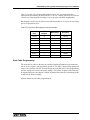
Port Programming . . . . . . . . . . . . . . . . . . . . . . . . . . . . . . . . . . . . . . . . . . . . . . . . . . . . . . .
Physical Node ID . . . . . . . . . . . . . . . . . . . . . . . . . . . . . . . . . . . . . . . . . . . . . . . . . . . . . . . .
Sample OPARAM.CDS. . . . . . . . . . . . . . . . . . . . . . . . . . . . . . . . . . . . . . . . . . . . . . . . . . . .
Enhanced Packet Routing . . . . . . . . . . . . . . . . . . . . . . . . . . . . . . . . . . . . . . . . . . . . . . . . .
TAP Outdial OPARAM Codes . . . . . . . . . . . . . . . . . . . . . . . . . . . . . . . . . . . . . . . . . . . . . . . . .
10
217
218
218
219
219
229
238
242
243
244
247
248
248
251
025-9035AA
Contents
Per-destination Parameters . . . . . . . . . . . . . . . . . . . . . . . . . . . . . . . . . . . . . . . . . . . . . . . . .
Modem-related Parameters . . . . . . . . . . . . . . . . . . . . . . . . . . . . . . . . . . . . . . . . . . . . . . . . .
Modem Programming Strings. . . . . . . . . . . . . . . . . . . . . . . . . . . . . . . . . . . . . . . . . . . . . . . .
The “.CUS” Files . . . . . . . . . . . . . . . . . . . . . . . . . . . . . . . . . . . . . . . . . . . . . . . . . . . . . . . . . . . .
Commands Found in OPTIONS.CUS . . . . . . . . . . . . . . . . . . . . . . . . . . . . . . . . . . . . . . . . .
Generic Function Codes . . . . . . . . . . . . . . . . . . . . . . . . . . . . . . . . . . . . . . . . . . . . . . . . . . .
Load Management . . . . . . . . . . . . . . . . . . . . . . . . . . . . . . . . . . . . . . . . . . . . . . . . . . . . . . . .
Commands within TRUNKS.CUS . . . . . . . . . . . . . . . . . . . . . . . . . . . . . . . . . . . . . . . . . . . .
Trunk-based Function Code Override Feature. . . . . . . . . . . . . . . . . . . . . . . . . . . . . . . . . . .
Commands within NETWORK.CUS. . . . . . . . . . . . . . . . . . . . . . . . . . . . . . . . . . . . . . . . . . .
TNPP and System Startup Events Reporting . . . . . . . . . . . . . . . . . . . . . . . . . . . . . . . . . . . . . .
Types of Events . . . . . . . . . . . . . . . . . . . . . . . . . . . . . . . . . . . . . . . . . . . . . . . . . . . . . . . . . .
Actions Taken. . . . . . . . . . . . . . . . . . . . . . . . . . . . . . . . . . . . . . . . . . . . . . . . . . . . . . . . . . . .
System Configuration Files . . . . . . . . . . . . . . . . . . . . . . . . . . . . . . . . . . . . . . . . . . . . . . . . .
EVENTS.CUS . . . . . . . . . . . . . . . . . . . . . . . . . . . . . . . . . . . . . . . . . . . . . . . . . . . . . . . . . . .
Events Table. . . . . . . . . . . . . . . . . . . . . . . . . . . . . . . . . . . . . . . . . . . . . . . . . . . . . . . . . . . . .
NETWORK.CUS . . . . . . . . . . . . . . . . . . . . . . . . . . . . . . . . . . . . . . . . . . . . . . . . . . . . . . . . .
Log Posting . . . . . . . . . . . . . . . . . . . . . . . . . . . . . . . . . . . . . . . . . . . . . . . . . . . . . . . . . . . . .
251
257
258
260
260
277
281
284
292
294
300
300
301
301
301
302
303
304
Remote Maintenance . . . . . . . . . . . . . . . . . . . . . . . . . . . . . . . . . . . . . . . . . . . . . 307
Overview of Communication with Paging Terminal . . . . . . . . . . . . . . . . . . . . . . . . . . . . . . . . . .
Installing ZlinkW . . . . . . . . . . . . . . . . . . . . . . . . . . . . . . . . . . . . . . . . . . . . . . . . . . . . . . . . . . . .
Starting and Exiting ZlinkW . . . . . . . . . . . . . . . . . . . . . . . . . . . . . . . . . . . . . . . . . . . . . . . . . . . .
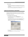
Configuring Communications from within ZlinkW . . . . . . . . . . . . . . . . . . . . . . . . . . . . . . . . . . .
ZlinkW Properties Fields . . . . . . . . . . . . . . . . . . . . . . . . . . . . . . . . . . . . . . . . . . . . . . . . . . .
Making a Connection from ZbaseW . . . . . . . . . . . . . . . . . . . . . . . . . . . . . . . . . . . . . . . . . . . . .
Modem Connections . . . . . . . . . . . . . . . . . . . . . . . . . . . . . . . . . . . . . . . . . . . . . . . . . . . . . .
Local Connections . . . . . . . . . . . . . . . . . . . . . . . . . . . . . . . . . . . . . . . . . . . . . . . . . . . . . . . .
IP Network Connections. . . . . . . . . . . . . . . . . . . . . . . . . . . . . . . . . . . . . . . . . . . . . . . . . . . .
ZlinkW Command Reference . . . . . . . . . . . . . . . . . . . . . . . . . . . . . . . . . . . . . . . . . . . . . . . . . .
ZlinkW File Operations. . . . . . . . . . . . . . . . . . . . . . . . . . . . . . . . . . . . . . . . . . . . . . . . . . . . .
ZlinkW “cards” . . . . . . . . . . . . . . . . . . . . . . . . . . . . . . . . . . . . . . . . . . . . . . . . . . . . . . . . . . .
ZlinkW “date” . . . . . . . . . . . . . . . . . . . . . . . . . . . . . . . . . . . . . . . . . . . . . . . . . . . . . . . . . . . .
ZlinkW “dos” . . . . . . . . . . . . . . . . . . . . . . . . . . . . . . . . . . . . . . . . . . . . . . . . . . . . . . . . . . . . .
ZlinkW “faultoff” . . . . . . . . . . . . . . . . . . . . . . . . . . . . . . . . . . . . . . . . . . . . . . . . . . . . . . . . . .
ZlinkW “get” . . . . . . . . . . . . . . . . . . . . . . . . . . . . . . . . . . . . . . . . . . . . . . . . . . . . . . . . . . . . .
ZlinkW “lastboot” . . . . . . . . . . . . . . . . . . . . . . . . . . . . . . . . . . . . . . . . . . . . . . . . . . . . . . . . .
ZlinkW “liu” . . . . . . . . . . . . . . . . . . . . . . . . . . . . . . . . . . . . . . . . . . . . . . . . . . . . . . . . . . . . . .
ZlinkW “log” . . . . . . . . . . . . . . . . . . . . . . . . . . . . . . . . . . . . . . . . . . . . . . . . . . . . . . . . . . . . .
ZlinkW “logopen” . . . . . . . . . . . . . . . . . . . . . . . . . . . . . . . . . . . . . . . . . . . . . . . . . . . . . . . . .
ZlinkW “ls” . . . . . . . . . . . . . . . . . . . . . . . . . . . . . . . . . . . . . . . . . . . . . . . . . . . . . . . . . . . . . .
ZlinkW Mailbox. . . . . . . . . . . . . . . . . . . . . . . . . . . . . . . . . . . . . . . . . . . . . . . . . . . . . . . . . . .
ZlinkW “newsdb” . . . . . . . . . . . . . . . . . . . . . . . . . . . . . . . . . . . . . . . . . . . . . . . . . . . . . . . . .
ZlinkW “niu” . . . . . . . . . . . . . . . . . . . . . . . . . . . . . . . . . . . . . . . . . . . . . . . . . . . . . . . . . . . . .
ZlinkW “note” . . . . . . . . . . . . . . . . . . . . . . . . . . . . . . . . . . . . . . . . . . . . . . . . . . . . . . . . . . . .
ZlinkW “page”. . . . . . . . . . . . . . . . . . . . . . . . . . . . . . . . . . . . . . . . . . . . . . . . . . . . . . . . . . . .
ZlinkW “reboot”. . . . . . . . . . . . . . . . . . . . . . . . . . . . . . . . . . . . . . . . . . . . . . . . . . . . . . . . . . .
ZlinkW “repeat”. . . . . . . . . . . . . . . . . . . . . . . . . . . . . . . . . . . . . . . . . . . . . . . . . . . . . . . . . . .
ZlinkW “search” . . . . . . . . . . . . . . . . . . . . . . . . . . . . . . . . . . . . . . . . . . . . . . . . . . . . . . . . . .
ZlinkW “siu” . . . . . . . . . . . . . . . . . . . . . . . . . . . . . . . . . . . . . . . . . . . . . . . . . . . . . . . . . . . . .
ZlinkW “tail” . . . . . . . . . . . . . . . . . . . . . . . . . . . . . . . . . . . . . . . . . . . . . . . . . . . . . . . . . . . . .
ZlinkW “time” . . . . . . . . . . . . . . . . . . . . . . . . . . . . . . . . . . . . . . . . . . . . . . . . . . . . . . . . . . . .
307
308
308
309
310
312
313
313
314
314
321
322
324
324
324
324
325
325
328
328
329
331
331
331
334
335
338
338
339
340
342
342
11
Contents
ZlinkW “traffic”. . . . . . . . . . . . . . . . . . . . . . . . . . . . . . . . . . . . . . . . . . . . . . . . . . . . . . . . . . .
ZlinkW “vls” . . . . . . . . . . . . . . . . . . . . . . . . . . . . . . . . . . . . . . . . . . . . . . . . . . . . . . . . . . . . .
ZlinkW “vget”, “vput” . . . . . . . . . . . . . . . . . . . . . . . . . . . . . . . . . . . . . . . . . . . . . . . . . . . . . .
ZlinkW Command Switches . . . . . . . . . . . . . . . . . . . . . . . . . . . . . . . . . . . . . . . . . . . . . . . .
Date & Time Switches . . . . . . . . . . . . . . . . . . . . . . . . . . . . . . . . . . . . . . . . . . . . . . . . . . . .
Switch Stacking . . . . . . . . . . . . . . . . . . . . . . . . . . . . . . . . . . . . . . . . . . . . . . . . . . . . . . . . .
Getting Help . . . . . . . . . . . . . . . . . . . . . . . . . . . . . . . . . . . . . . . . . . . . . . . . . . . . . . . . . . . .
Log Posting Format . . . . . . . . . . . . . . . . . . . . . . . . . . . . . . . . . . . . . . . . . . . . . . . . . . . . . . . . .
Paging Format Letters . . . . . . . . . . . . . . . . . . . . . . . . . . . . . . . . . . . . . . . . . . . . . . . . . . . .
Overdialed And Call Recycle Posting . . . . . . . . . . . . . . . . . . . . . . . . . . . . . . . . . . . . . . . . .
New Destination Type (Log +) . . . . . . . . . . . . . . . . . . . . . . . . . . . . . . . . . . . . . . . . . . . . . .
“set” Command . . . . . . . . . . . . . . . . . . . . . . . . . . . . . . . . . . . . . . . . . . . . . . . . . . . . . . . . . .
Posting . . . . . . . . . . . . . . . . . . . . . . . . . . . . . . . . . . . . . . . . . . . . . . . . . . . . . . . . . . . . . . . . . . .
Classes of Calls . . . . . . . . . . . . . . . . . . . . . . . . . . . . . . . . . . . . . . . . . . . . . . . . . . . . . . . . . . . .
Results of Calls . . . . . . . . . . . . . . . . . . . . . . . . . . . . . . . . . . . . . . . . . . . . . . . . . . . . . . . . . . . .
Sucess Results . . . . . . . . . . . . . . . . . . . . . . . . . . . . . . . . . . . . . . . . . . . . . . . . . . . . . . . . . .
Failure Results . . . . . . . . . . . . . . . . . . . . . . . . . . . . . . . . . . . . . . . . . . . . . . . . . . . . . . . . . .
Warning Results . . . . . . . . . . . . . . . . . . . . . . . . . . . . . . . . . . . . . . . . . . . . . . . . . . . . . . . . .
Error Results. . . . . . . . . . . . . . . . . . . . . . . . . . . . . . . . . . . . . . . . . . . . . . . . . . . . . . . . . . . .
System Errors (Call not processed) . . . . . . . . . . . . . . . . . . . . . . . . . . . . . . . . . . . . . . . . . .
Typical Bootup Sequence . . . . . . . . . . . . . . . . . . . . . . . . . . . . . . . . . . . . . . . . . . . . . . . . . . . .
Paging Traffic Display . . . . . . . . . . . . . . . . . . . . . . . . . . . . . . . . . . . . . . . . . . . . . . . . . . . . . . .
342
343
344
345
345
346
346
346
347
349
349
350
351
352
354
354
355
356
357
357
358
359
Appendix A: TAP Protocol Summary. . . . . . . . . . . . . . . . . . . . . . . . . . . . . . . . . 361
Definitions . . . . . . . . . . . . . . . . . . . . . . . . . . . . . . . . . . . . . . . . . . . . . . . . . . . . . . . . . . . . . . . .
Protocol . . . . . . . . . . . . . . . . . . . . . . . . . . . . . . . . . . . . . . . . . . . . . . . . . . . . . . . . . . . . . . . . . .
Initial Handshake Sequence . . . . . . . . . . . . . . . . . . . . . . . . . . . . . . . . . . . . . . . . . . . . . . . .
Initial Logon Sequence . . . . . . . . . . . . . . . . . . . . . . . . . . . . . . . . . . . . . . . . . . . . . . . . . . . .
Transferring Pages . . . . . . . . . . . . . . . . . . . . . . . . . . . . . . . . . . . . . . . . . . . . . . . . . . . . . . .
Checksum Example . . . . . . . . . . . . . . . . . . . . . . . . . . . . . . . . . . . . . . . . . . . . . . . . . . . . . .
362
362
362
363
364
366
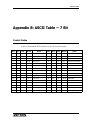
Appendix B: ASCII Table — 7 Bit . . . . . . . . . . . . . . . . . . . . . . . . . . . . . . . . . . . . 367
Control Codes . . . . . . . . . . . . . . . . . . . . . . . . . . . . . . . . . . . . . . . . . . . . . . . . . . . . . . . . . . . . . 367
Printable Characters . . . . . . . . . . . . . . . . . . . . . . . . . . . . . . . . . . . . . . . . . . . . . . . . . . . . . . . . 368
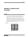
Appendix C: Decimal to HEX Conversion . . . . . . . . . . . . . . . . . . . . . . . . . . . . . 369
Overview . . . . . . . . . . . . . . . . . . . . . . . . . . . . . . . . . . . . . . . . . . . . . . . . . . . . . . . . . . . . . . . . . 369
Examples . . . . . . . . . . . . . . . . . . . . . . . . . . . . . . . . . . . . . . . . . . . . . . . . . . . . . . . . . . . . . . . . . 370
Index . . . . . . . . . . . . . . . . . . . . . . . . . . . . . . . . . . . . . . . . . . . . . . . . . . . . . . . . . . . 373
12
025-9035AA
Purpose of This Manual
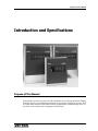
Introduction and Specifications
Purpose of This Manual
This manual is provided to assist you in the installation of your Zetron 2000 Series Paging
Terminal. Step-by-step installation instructions are provided to simplify the process. Also
provided in this manual is information relating to adjustments, troubleshooting, theory of
operation, and a complete list of equipment specifications.
13
Introduction and Specifications
Contents of This Manual
This manual is divided into twelve sections and three appendices. The following
paragraphs contain a synopsis of each section and describe the basic purpose and content
of each.
• INTRODUCTION AND SPECIFICATIONS
This section contains the specifications for the paging terminal as well as the trunk
cards, station cards, voice storage system, etc.
• SYSTEM INSTALLATION
This section contains the information necessary to install and adjust the paging
terminal. The information is contained in the form of checklists and step-by-step
procedures. Where appropriate, procedures in this section refer to information
contained in other sections of this manual. This is the first section you will read in
this manual.
• INSTALLING THE OFFICE SOFTWARE
This section discusses the connection of the office computer to the paging terminal.
A simple procedure is given to load the software. It also covers starting and exiting
the database program.
• TRUNK CARDS AND CONNECTIONS
This section provides information that relates to the telco side of the paging
terminal. It contains detailed connection listings for the RJ21 trunk connectors
located on the backplane of the paging terminal that are used to make the
connections to the telephone company lines. It also tells how the trunk cards operate
and how to configure a trunk card for DID, E&M, or E-E operation. Adjustment
procedures are given for the trunk cards as well as for the optional dial click cards.
• RADIO SYSTEM
This section provides information that relates to the radio side of the paging
terminal. It contains detailed connection listings for the radio station connectors
located on the backplane of the paging terminal that are used to make the
connections to the radio transmitter equipment. It also tells how the station cards
operate and how to configure the jumpers on a station card and make any necessary
adjustments. This section also describes the different paging terminal/radio
transmitter hook-up arrangements, including remote control operation. Illustrations
are provided to support the hook-up descriptions.
• MULTIPORT SERIAL TAP INPUT
This section describes the installation and operation of the multiport serial card for
alphanumeric page entry and its function as a TNPP interface.
• MULTIPORT FOR TNPP & TAP OUTDIAL
This section presents an overview of TNPP networking for paging terminals and
general information on Zetron's implementation of TNPP. It covers usage of TNPP
with various ZbaseW and ZPAGE versions and describes the information used to
configure TNPP on a terminal.
14
025-9035AA
Contents of This Manual
• THEORY OF OPERATION
This section presents the theory of operation for the paging terminal. Circuit
descriptions are provided for each of the cards. This section also contains a
complete set of charts that describe the sequence of events that takes place when
call are processed by the paging terminal (call processing charts). A complete set of
timing diagrams for the telco side of the system and the radio side of the system is
contained at the back of the section.
• TROUBLESHOOTING AND REPAIR PROCEDURES
This section provides some troubleshooting information that you can use when
clearing problems in the paging terminal. The information provided covers
symptoms/remedies, front panel lamp indications, progress tones, and the office
computer.
• VOICE STORAGE SYSTEM
This section describes the voice storage system used in the paging terminal. It
describes the operation of the voice system, how to install the voice card, how to set
the mode switches on the card, how to use the test pins to troubleshoot the voice
card, and how to upgrade the software on the card. It also covers how to save and
restore sets of voice files or individual voice files.
• SYSTEM CONFIGURATION FILES
This section describes the oparam.cds and various configuration control files. This
file contains information about your system that is used by the microprocessor and
its software to control your paging terminal. While this file is created at the factory
to suit your particular needs, it is described in this section in the event you wish to
change the configuration of your system. To determine just what aspects of paging
terminal operation this file controls, read the entire section and examine A copy of
your oparam.cds file using a text editor or the DOS type command.
• REMOTE MAINTENANCE
This section describes the operation of ZlinkW; the full-duplex Zetron
communications program provided to remotely control your paging terminal.
• APPENDIX A. TAP PROTOCOL SUMMARY
This appendix describes the Telocator Access Protocol (TAP), which is a protocol
derived from the Motorola iXO protocol.
• APPENDIX B. ASCII TABLE, 7-BIT
• APPENDIX C. DECIMAL TO HEX CONVERSION
15
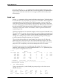
Introduction and Specifications
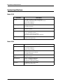
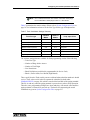
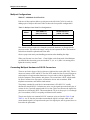
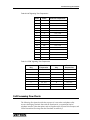
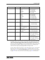
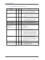
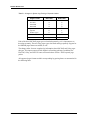
System Specifications
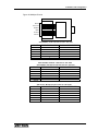
Model 2100
Parameter
Description
Physical
21" tall, 20" wide, 5.5" deep (wall mount)
19" rack, 12 rack units tall, 5.5" deep (rack mount)
40 lb. fully configured
Wall or rack mounting
Power Supply
AC input: 115/230 volts AC +/- 10%, 47-63 Hz
150 Watts maximum
Uninterruptible Power
Supply
400 VA
30 minute capacity
Environmental
+40 to +120 degrees Fahrenheit
(+5 to +50 degrees Celsius)
10,000 foot (3,000 meter) altitude
8% to 80% relative humidity, non-condensing
Card Slots
5 computer, 3 telco, 2 telco/radio
Positive lock retainer bars
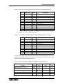
Model 2200
Parameter
16
Description
Physical
30" tall, 22" wide, 7" deep
75 lb. fully configured
Wall or frame mounting
Power Supply
AC input: 115/230 volts AC +/- 10%, 47-63 Hz
DC input option: 40-70 volts DC
300 Watts maximum
Uninterruptible Power
Supply
400 VA
30 minute capacity
Environmental
+50 to +120 degrees Fahrenheit
(+10 to +50 degrees Celsius)
10,000 foot (3,000 meter) altitude
Card Slots
6 computer, 6 telco, 4 telco/radio
Positive lock retainer bars
025-9035AA
System Specifications
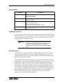
Model 2200EX
Parameter
Description
Physical
30" tall, 22" wide, 7" deep
75 lb. fully configured
Wall or frame mounting
Power Supply
AC input: 115/230 volts AC +/- 10%, 47-63 Hz
200 Watts maximum
Environmental
+40 to +120 degrees Fahrenheit
(+5 to +50 degrees Celsius)
10,000 foot (3,000 meter) altitude
8% to 80% relative humidity, non-condensing
Card Slots
6 computer, 10 telco, 4 telco/radio
Positive lock retainer bars
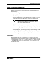
Lightning Protection
Arc arresters right on the telephone demarcation/punch-down blocks can shunt hazardous
voltages at their source. These easily replaced protection modules protect your equipment
investment and increase client satisfaction. Ask your Zetron sales person how to order
punch down blocks with built in protectors.
!
Caution!
Operating the 2100/2200/2200EX without adequate voltage
suppression devices on the telephone and radio connections
may result in costly damage not covered by warranty.
Protection kits and applications assistance are available from
Zetron.
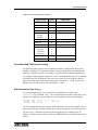
Operating Power
The internal power supply on the Model 2100/2200/2200EX operates from 115 or 230
volts AC and provides all internal operating voltages, including the 48 volts for DID
telephone trunks. A power supply option is available to operate the Model 2200 directly
from 48V telco-style battery supply.
An uninterruptible power supply (UPS) option (802-9049) obtains standby power from
storage batteries and keeps the system operating through brownouts or blackouts. Zetron's
standard UPS is a 400VA unit with 30 minute capacity (P/N 802-9049) with built in
storage batteries. Higher capacity UPS options may be available as required. With an
uninterruptible power supply, the paging messages can go into high capacity storage (up
to 30 minutes of typical paging) until the power returns. DID trunks remain in service to
keep the telephone company happy. With the radio station also on uninterruptible power,
paging and messaging traffic can ride through power losses with no interruption of
service. Other UPS equipment can provide more capacity and even power radio
equipment; call Zetron for applications assistance.
17
Introduction and Specifications
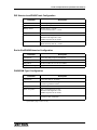
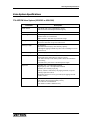
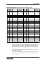
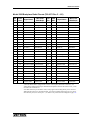
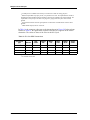
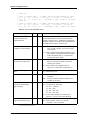
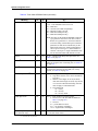
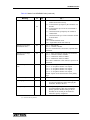
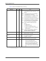
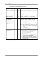
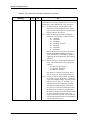
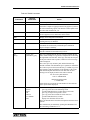
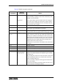
Trunk Card Specifications (702-9037 and 702-9117)
Parameter
18
Description
Field Configured
Central office DID selector-level
PABX 2-wire trunk
End-to-End loop start ring and overdial
E&M Type I 2-Wire Audio (FIC TL-11E)
Local operator telephone set/CRT/computer
End-to-End ground start and overdial
Alpha Messaging
Remote TAP compatibility (requires modem option)
Local RS-232C or VDT (702-9037 only)
ASCII 7 bits, 2-Stop, Even Parity
Card Status Lamps
Select, Test 1, Test 2, Test 3
Line Status Lamps
Ring, Loop, Answer, Modem
Input
DTMF 16-tone pairs (0-9,*,#,A-D)
Dial pulse (digits 0-9)
Modem 300-baud ASCII (1200-baud 702-9117 only)
Dial click option (digits 0-9)
MF decoder option
Connector
Board edge to 50-pin RJ2EX for 10 telcos
Telco Audio Input
Voice AGC limited -28 dBm to +10 dBm
DTMF overdial tones -35 dBm to +6 dBm
Modem tones -35 dBm to -6 dBm
Voice silence detect -20 dBm +/-3 dBm threshold
Progress tones designed for networking
Telco Audio Output
Progress tones/voice -17 dBm to -6 dBm
DTMF, Modem tones -13 dBm to -3 dBm
Audio Bandwidth
300 to 3500 Hz +/-1 dB
DTMF Detect
Standard 16-tone pair frequencies
Minimum tone-pair duration 45 ms
Minimum Inter-digit Time 45 ms
Up to 11 digits per second
Disconnect
no loop current (programmable, 150 ms & up)
Detect
no VOX (programmable, 2500 ms & up)
dial tone detect (programmable, 3000 ms & up)
digit input timeout (programmable, 5 sec. & up)
Modem Data
300- or 1200-baud 103J Answer/Originate
Programmable byte framing, XON/XOFF Burst Handshake
Line Coupling
600-ohm Transformer, Adjustable balance duplex hybrid
FCC Registration
EYB5Q5-19269-OT-E, REN: 0.4B
DOC Registration
702-9117 Revision D and later only trunk circuits.
Load Number: 69
025-9035AA
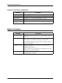
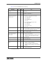
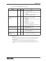
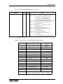
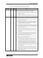
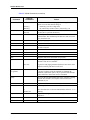
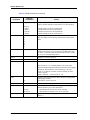
Trunk Card Specifications (702-9037 and 702-9117)
DID Selector Level/PABX Trunk Configuration
Parameter
Description
Connections
2-wire Tip, Ring
Supervision
Reverse battery
Battery Source
To telco 48 V +/-3 V DC
Current limited 40 mA +/-10 mA
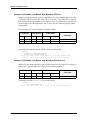
Loop Closure
Detect threshold 6 mA +/-3 mA
Pulse Acceptance
Rate 5 to 22 pulses per second
Minimum inter-digit time 78 ms
DTMF acceptance 40 to 300 ms
Supervision Control
Immediate dial 150 ms +/-50 ms
Wink start delay 240 ms +/-20 ms
End-to-End/PABX Extension Configuration
Parameter
Description
Connections
2-wire Tip, Ring; Loop or Ground Start
Battery Source
From Telco/PABX
Ring Detect
16 Hz to 66 Hz; 40 V to 150 V ACRMS
Answer After Ring
Programmable 0 to 30 seconds delay
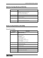
PABX E&M Type I Configuration
Parameter
Description
Connections
5-wire Tip, Ring, E, M, Earth
Supervision
Closure to -48V on M-lead
Closure to ground on E-lead1
Battery Source
From Telco / From Terminal; Current limited 15mA1
Pulse Acceptance
Rate 5 to 22 pulses per second
Minimum inter-digit time 78 ms
DTMF acceptance 40 to 300 ms
Answer Supervision
Closure to ground on E-lead 150 ms +/-50 ms
Closure to -48V on M-lead1
1 Special
Matrix plug on 702-9117 only.
19
Introduction and Specifications
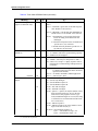
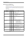
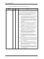
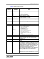
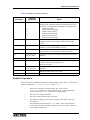
Operator Local Phone Configuration
Parameter
Description
Connections
2-wire tip, ring
Supervision
Reverse battery, answer beeps or computer modem
Battery Source
To phone 48 +/- 3 V DC; Current limited 40 +/- 10 mA
Loop Closure
Detect threshold 6 mA +/- 3 mA
Pulse/DTMF
Acceptance
(see DID Selector Level/PABX Trunk Configuration on page 19)
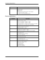
Digital T1 Interface
Parameter
Description
System Requirements
2000 Series Paging Terminal must have high performance Pentium
CPU card
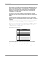
Capacity
Up to 24 channels of T1 support per each T1 Interface (partial T1
trunk support can be achieved using fewer trunk cards)
A 2000 Series Paging can support two T1 Interface units for a
total of 48 channels
20
Compatible CSU units
Interface to PSTN requires the use of a CSU, approved units are:
Import T1 CSU 1544
AT&T ESF CSU 551E-L1, A
(Please contact Zetron for information on any additional CSU units
that may have been added to the list.)
Power
AC Input 85 to 264 VAC at 47 to 440 Hz, 130 W max.
DC (Optional) 36 to 76 VDC
025-9035AA
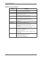
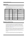
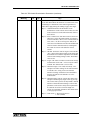
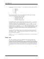
Multi-Port Card Specifications (702-9191)
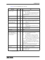
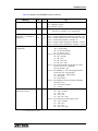
Multi-Port Card Specifications (702-9191)
Parameter
Description
Input
2, 4, 6 or 8-port
ASCII 7 bits, 1 stop, even or odd parity
ASCII 8 bits, 1 stop, no parity
150, 300, 600, 1200 or 9600 baud
Card Status Lamps
Select, Test 1, Test 2, Test 3
Port Status Lamps
Channel 1, Channel 2, Channel 3, Channel 4 Channel 5, Channel 6,
Channel 7, Channel 8
Connector
Punchdown block via supplied interface cable
- or 2000 Series Octopus Cable (709-5008)
Controls
Eight-position DIP switch to select card address
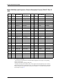
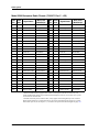
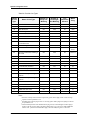
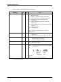
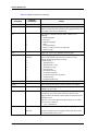
Station Card Specifications (702-9038)
General Specifications
Parameter
Description
Configurations
Transmit only Paging
Transmit/Receive Talk-back
Signaling Formats
2-tone sequential
5/6-tone sequential
HSC analog
POCSAG binary digital
GSC binary digital
NEC D3, D4 binary digital
Multitone Mark IV/V (special order)
FLEX 1600 Baud
Software loadable format expansion
Batching
Multiple batches
Automatic priority aging
Morse Code ID
Programmable automatic station ID
1200 Hz at 20 wpm
Connector
Board edge to 50-pin connector
Card Status Lamps
Select, Test 1, Test 2, Test 3
Channel Status Lamps
Request, COR/CAS, Analog PTT, Digital PTT, Data Busy, Aux,
Zone 1, Zone 2, Zone 4, Zone 8
Remote Control
GE/Motorola tone remote option
21
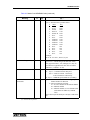
Introduction and Specifications
Parameter
Compatible Controllers
Description
Motorola PSC, SSC
Quintron Omega
Microlink 20T
Controllers with Ana PTT, Dig PTT, Audio, and Data
• Must be true FSK (i.e. NRZ)
• PURC or Cresent controlled transmitter
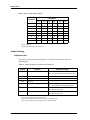
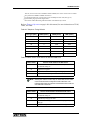
Electrical Specifications
Parameter
22
Description
Transmit Audio
Balanced 600 ohm transformer
250 Hz to 3500 Hz +/-1dB
Voice Level Adjustable -20dBm to +4dBm
Tone Level Adjustable -20dBm to +4dBm
Selectable Flat Tone or -6 dB per octave De-emphasis 300-3000Hz
Selectable Flat Voice or +6 dB per octave Pre-emphasis
Format Encoding
Analog frequency accuracy +/-0.02%
Analog tone distortion less than 0.2%
Digital data stability +/-2 ppm
Receive Audio
Balanced 600 ohm transformer
Adjustable Level -20dBm to +10dBm
Selectable Flat Frequency or -6 dB per octave De-emphasis
Digital Encoding
Binary data
Analog/digital mode
Programmable polarity and timing
RS-232 level compatible
Zone Select
4 zone selects (1-16 zones)
Open collector, 40 mA sink
Keying Outputs
3 relays, SPDT contacts
rated, 1 Amp at 26 V AC
Analog PTT, Digital PTT, Aux PTT
Station Handshaking
Request station (output)
Station busy (COR/CAS input)
Terminal busy (input)
Selectable polarity
Programmable timing
RS-232 level compatible
025-9035AA
Voice System Specifications
Voice System Specifications
ITU ADPCM Voice System (950-0385 or 950-0386)
Parameter
Description
Audio In/Out
8-bit PCM with u-Law companding to 12 bits
Time division PCM multiplexed audio highway
Audio Bandwidth
200 Hz to 3400 Hz, +/- 1 dB
Recording Method
Transcoding to 4-bit ADPCM at 32Kbits/sec
Double buffers for each channel
DMA transfer to hard disk for permanent storage
Storage
Files in protected partition of hard disk
End-of-file indication for precise audio cutoff
Message Length
No minimum
Maximum limited only by mass memory capacity
(although the paging terminal may limit voice recordings to a more
practical size)
End of Message
Precision replay without wasting voice time
Pause Compression
Software selectable
Performed before disk transfer to conserve activity
Fast audio attack prevents initial syllable cutoff, also minimizes
noise falsing
Selectable decay rate allows customized pause length
Operation
Standard card = 14 independent channels
High capacity card = 28 independent channels
Each may be recording or playing
Entirely software controlled by the paging terminal, no special
training required for callers
Diagnostics and error recovery provided by the paging terminal
control software
LED Indicators
One LED to show voice memory activity
One LED to show program memory activity
Two LEDs for test information
Four LEDs to indicate channel activity
23
Introduction and Specifications
ADPCM Voice System (950-9061)
Parameter
24
Description
Audio In/Out
8-bit PCM with u-Law companding to 12 bits
Time division PCM multiplexed audio highway
Audio Bandwidth
200 Hz to 3400 Hz, +/- 1 dB
Recording Method
Transcoding to 4-bit ADPCM at 32Kbits/sec
Double buffers for each channel
DMA transfer to hard disk for permanent storage
Storage
Files in protected partition of hard disk
End-of-file indication for precise audio cutoff
Message Length
No minimum
Maximum limited only by mass memory capacity
(although the paging terminal may limit voice recordings to a more
practical size)
End of Message
Precision replay without wasting voice time
Pause Compression
Software selectable
Performed before disk transfer to conserve activity
Fast audio attack prevents initial syllable cutoff, also minimizes
noise falsing
Selectable decay rate allows customized pause length
Operation
Sixteen independent channels
Each may be recording or playing
Entirely software controlled by the paging terminal, no special
training required for callers
Diagnostics and error recovery provided by the paging terminal
control software
LED Indicators
One LED to show voice memory activity
One LED to show program memory activity
Two LEDs for test information
Four LEDs to indicate channel activity
025-9035AA
Overview
System Installation
Overview
This section contains the information necessary to install and adjust the paging terminal.
The information is contained in the form of checklists and step-by-step procedures. Where
appropriate, procedures in this section refer to information contained in specific sections
elsewhere in this manual.
Installation of the 2000 Series Paging Terminal is usually accomplished in three major
steps:
• Connect a telco line (or local telephone) and the radio system in a temporary setup
for checkout and make it ready for rapid cut over into an existing system. (If this is
a new installation, you can install the system in its permanent location and connect
the new telco lines for checkout.)
• Install the system software onto the office computer, enter pagers into the database,
and perform some test paging operations.
• Mount and connect the working system into its permanent installation.
The installation procedures contained in this section consist of the three basic operations
listed above to connect the system temporarily, perform some test pages, and then install
the paging terminal in its permanent location. An installation procedure/checklist is
provided that lists the specific steps to take during installation of the paging terminal, and
where necessary, refers to more detailed information contained in other sections of this
manual.
To install the paging terminal in your facility, complete each of the steps (in order) of the
Installation Checklist contained on the following pages.
STOP
Warning! ALWAYS TURN OFF POWER BEFORE INSERTING OR
REMOVING CARDS!
Removing or inserting cards with power on can cause serious
damage to your terminal. The 2000 Series Paging Terminals
use a bus backplane much like a personal computer, and are
not designed for “hot” removal of cards.
25
System Installation
Installation Checklist
This installation checklist is provided as a “to do” list that will guide you through the steps
necessary to install the paging terminal and its operating software. Follow the steps in the
checklist to install the paging terminal.
This checklist consists of specific instructions, and in some instances, references to other
instructions contained in this manual. When a step in the installation checklist refers you
to another procedure in the manual, complete that procedure and then return to where you
left off in the checklist.
1. [_] Unpack and open the paging terminal cabinet.
Unpack the Model 2100/2200 from largest box (save the box).
Remove the front door (screw latches on Model 2200)
Remove the top cover (unscrew, slide toward you, and tilt up on the Model 2200;
on the Model 2100, remove 10 screws)
You can check your order against the received items.
2. [_] Complete step a or b, depending on the CPU option supplied with your system:
a. Install the hard disk card. (See Hard Disk Card Mounting Information on page
32, for more details.)
Unpack the hard disk card from shipping smaller box.
Remove the #4-40 screw from card slot #1. Figure 2-1 shows the location of
the hard disk card in the paging terminal.
Install the hard disk card and secure with the #4-40 screw.
No formatting is necessary.
b. Verify that the SCSI disk is mounted in the bottom section of the chassis.
(Refer to SCSI Disk Card Mounting Information (M2200) on page 32, for more
details.)
3. [_] Make sure all circuit cards, in each and every occupied slot, are firmly seated in
the paging terminal cabinet.
4. [_] The office computer that operates the paging terminal’s database can be
connected as a remote connection or a local connection. Depending on whether
you are installing a remote connection or a local connection, for the office
computer, perform either step a. or b.
Note
26
For remote computer connection, the paging terminal is equipped
with a US Robotics 56 kbs modem, installed in the slot shown in the
paging terminal diagrams. This card allows communication with the
computer via a dial-up telephone line. For local computer
connection, the paging terminal is equipped with RS-232C serial
data capability. This allows communication with the computer via a
direct cable link.
025-9035AA
Installation Checklist
a. [_] Plug the RJ-11C modular jack of a telco cable to the top of the modem card
into the jack labeled LINE or WALL (do not use the jack labeled PHONE).
Connect the other end of the telco cable directly to the telephone wall jack.
b. [_] Connect the supplied Local Serial cable to the serial port (the mounting
bracket on the lower backplane.
Figure 1: Location of Model 2200 Paging Terminal Components
2000 MASTER CARD
MAINTENANCE MODEM CARD
PENTIUM CPU CARD
1
TRUNK CARDS
TRUNK/TAP-TNPP SERIAL CARDS
TRUNK/STATION CARDS
STATION CARDS
ADPCM
VOICE CARD
2
3
4
5
6
7
8
9
10
11
12
13
14
15
16
SCSI
CABLE
SERIAL PRINTER
PORT (Optional)
LOCAL
PROGRAMMING
PORT
SCSI DISK
POWER
CABLE
POWER SUPPLY
MOUNTING BRACKETS
FRONT PANEL OF DRIVE
WITH RED LED
Model 2200 (Pentium C PU)
Figure 2: Location of Model 2100 Paging Terminal Components
ADPCM - VOICE CARD
ZETRON CPU CARD
TRUNK CARDS
MEMORY CARD
TAP - TNPP
SERIAL CARDS
MODEM CARD
HARD DISK CARD
STATION CARD
1
2
3
4
5
6
7
8
9
10
SERIAL PRINTER PORT
LOCAL PROGRAMMING
PORT
Model 2100 - Zetron CPU
27
System Installation
5. [_] Plug the paging terminal unit into the appropriate AC power source and switch
on the power. On the Model 2200, the switch is located on the right-side panel; on
the Model 2100 the switch is located inside the front door of the cabinet.
Note
If an expansion chassis is part of the system, the expansion chassis
must be powered up at the same time (or before) the main chassis
is powered up.
6. [_] With power applied to the paging terminal, check front panel lights for correct
operation as described in Front Panel Lights on page 182.
7. [_] At this point, you can connect either the telephone lines designated for the
trunk cards of the paging terminal, or a test telephone that connects temporarily for
testing purposes.
Connect the telephone lines, or the test telephone, to the trunk card(s) via the
RJ2EX connectors on left side of the lower backplane shown in Figure 3 or Figure
4. Refer to TELCO Connectors on page 72 for specific connection information.
Refer to the configuration packet you received from Zetron along with the terminal
for information on how the telephone trunks were programmed at the factory.
Figure 3: Model 2200 Telephone and Transmitter Connectors
J19
BACKPLANE
J20
J21
TELEPHONE LINE
CONNECTORS
J22
TRANSMITTER
CONNECTORS
Figure 4: Model 2100 Telephone and Transmitter Connectors
J13
BACKPLANE
28
TELEPHONE LINE
CONNECTORS
J14
TRANSMITTER
CONNECTORS
025-9035AA
Installation Checklist
8. [_] Connect the transmitter equipment (or test/measurement equipment if the
transmitter cannot be connected at this time) to the station card(s) of the paging
terminal.
Connection the transmitter/test equipment to the station card(s) via the connectors
on the right side of the lower backplane (see Figure 3 or Figure 4). Refer to Radio
Connectors on page 98, for specific connection information.
An amplified speaker can be connected to the XMIT and GND outputs on the front
of the Station card for monitoring analog paging in absence of a transmitter.
Note
Only tone and voice can be monitored by this method, unless tone
remote control is used. Then digital can be heard as modem tones.
9. [_] Install the office computer software; ZbaseW, ZlinkW, etc. Refer to Installing
the Office Software on page 55. (For more complete information on the ZbaseW
program, see the Series 2000 Operation and Programming manual, 025-9034-001.)
10. [_] If you have any trouble linking up to the paging terminal with ZlinkW, refer to
the Troubleshooting the Office Computer on page 186.
11. [_] To test operation of the paging terminal, it is necessary at this point to create a
“test” subscriber database. This database is created by using ZbaseW on your
office computer as described in Installing Office Software on page 57. (For
additional information on the ZbaseW program, see the Series 2000 Operation and
Programming manual, 025-9034-001.)
12. [_] Make several test pages and verify pagers activate and audio levels are correct.
Note that the telephone trunk circuitry contains AGC circuitry that boosts recorded
audio to its maximum. Therefore, do not use the FROM TEL adjustments for audio
level adjustment; instead, use the adjustments on the Station card per the next
subsection, Alignment Procedure on page 30.
If you experience difficulty getting the system to operate normally, refer to
Troubleshooting and Repair Procedures on page 179.
13. [_] Mount the paging terminal in its final location (see Figure 5).
a. For the Model 2200, remove the bottom cover (unscrew, slide toward you, and
tilt down). Then remove the hard disk card, and the circuit cards from slots 1,
2, 15, and 16 to gain access to the mounting holes on the back panel of the
paging terminal. Refer to Model 2200 Cabinet Mounting Information on page
36 for details.
b. For the Model 2100, attach the mounting brackets to the side panels with
hardware supplied. Attach the paging terminal to the wall with lag screws, or
to an equipment rack with supplied hardware. Refer to Model 2100 Cabinet
Mounting Information on page 36 for details.
14. [_] Make all permanent telephone line connections to the RJ2EX connectors on the
left side of the backplane and radio transmitter connections to the connectors on
the right side of the backplane. Refer to Figure 3 or Figure 4.
29
System Installation
Figure 5: Example of System Installation (including Expansion Unit)
Alignment Procedure
The following alignment procedure should be performed on the paging terminal after
installation is complete in order to assure correct operation and optimum signal levels.
We recommend that you use the following test equipment:
• a Touch-Tone (DTMF) telephone that can call the paging terminal
• an AC voltmeter
• a communications service monitor
• a 2-tone tone & voice pager tuned for your paging channel
The alignment procedure is provided as a “to do” list (similar to that given for system
installation) that will guide you through the steps necessary to align/adjust the paging
terminal. Follow the steps in the checklist to install the paging terminal.
30
025-9035AA
Alignment Procedure
1. [_] At the office computer, use ZbaseW to program the subscriber database with a
few 2-Tone tone & voice pagers. (For more complete information on the ZbaseW
program, see the Series 2000 Operation and Programming manual, 025-9034001.). For alignment purposes, use the following values for creating a subscriber
database:
2 pagers:
- Voice Limit = 60 seconds
- Tone Length = 12 seconds
- Tone Freq. = 500Hz, 1000Hz
1000Hz, 2000Hz
If you are using digital paging, also set up a digital pager.
Also program a subscriber number for voice prompt access (Status = P).
Once these test pages are programmed, be sure to update the paging terminal via
Comm Update.
2. [_] Trunk adjustments:
Refer to “Adjustment Procedures” in the Trunk Cards section for details on
adjusting the incoming (From Tel Adjustment on page 77), outgoing (To Tel
Adjustment on page 77), and hybrid balance levels (Hybrid Adjustment on page 78)
on each of your trunk lines. Then return here and proceed to step 3.
Note
This balance adjustment will change if you or your telephone
company changes any telephone wiring.
3. [_] Station RF deviation adjustments:
VOICE Audio Adjust:
a. Call the 2-Tone tone & voice pager. During the voice message time, hold
down a key on your Touch-Tone telephone, so you record a long Touch-Tone.
b. With your service monitor, measure the RF deviation of your radio
transmission. While the Touch-Tone key that you recorded is playing, adjust
the “XMIT AUDIO” pot on the front of the Station card for about 3.0 - 4.0kHz
deviation.
c. Call the pager again and this time speak during the voice time. While your
voice is playing out, check the deviation again to make sure it is about 4.5kHz
during the loudest parts.
TONE Audio Adjust:
a. Call the first 2-Tone pager (the one with 500 & 1000Hz tones). Hang up after it
beeps you for voice, we do not need voice.
b. With your service monitor, measure the RF deviation of your radio
transmission. While the tones (of the 2-Tone pager) are playing, adjust the
“XMIT TONE” pot on the front panel of the Station card for 3.5 to 4.0kHz
deviation. Check to see if the level varies when it changes from 500 to
1000Hz.
31
System Installation
c. Repeat the two preceding steps but use the other test pager with the 1000 &
2000Hz tones. You should find that your channel deviation is independent of
tone frequency. Consult Zetron if your modulation is not “flat”.
4. [_] DIGITAL deviation adjustment:
RF deviation levels on binary digital transmissions are determined by your
transmitter, not by the station card.
To adjust, call a digital pager, and while the digital data is going out, use your
service monitor to adjust your transmitter for 4.5 to 5kHz deviation.
Hard Disk Card Mounting Information
The Zetron hard disk on a card for the Zetron Model 2100/2200 paging terminal is packed
separately to avoid damage to the terminal or hard disk during shipment. The hard disk
contains all of the software for the paging terminal; therefore, it must be installed before
operation of the paging terminal can take place. Installation is simple, but the hard disk
can be easily damaged. Please follow the instructions below:
1. Be sure power to the Model 2200/2100 Paging Terminal is turned off.
2. Open the packaging material containing the hard disk. It is a good idea to save the
packing materials, including the static-proof jacket, in the event you should ever
need to ship your hard disk.
!
Caution!
AVOID TOUCHING THE GOLD-PLATED CARD-EDGE FINGERS
3. While holding the hard disk card at the top (card-edge finger side) and bottom,
align it with the left-most card guide and the card slot. Check to make sure the
gold-plated card-edge fingers are centered over the connector. Now firmly press on
the top edge of the hard disk above the connector until it is firmly seated in the
connector.
4. Use the #4-40 screw you removed to fasten the hard disk card. Do not operate the
paging terminal until the hard disk is firmly fastened.
SCSI Disk Card Mounting Information (M2200)
The SCSI disk for the Model 2200 Pentium option is packed separately to avoid damage to
the terminal or hard disk during shipment. Please follow the instructions below to install
the SCSI disk in the Model 2200 (Refer to Figure 1 and Figure 6):
1. Be sure power to the Model 2200 Paging Terminal is turned off.
2. Attach the two supplied brackets to the SCSI disk using the supplied screws.
32
025-9035AA
TELCO Ground Reference
3. Connect one end of the 50-pin SCSI cable to the SCSI drive with the stripped edge
toward the drive's power connector. Connect the other end to connector J1 on the
Pentium CPU card (see Figure 6). The stripped edge should be towards pin 1,
which means the bottom on the card.
4. Connect the power cable to the mating connector at the left end of the power
supply.
5. Fasten the SCSI disk with brackets to the terminal at the location of the pre-drilled
holes.
TELCO Ground Reference
Proper telephone interface operation requires a good ground reference from the chassis of
the Model 2100 or 2200 to the Telephone Company ground. You should run a heavy wire
(#16 AWG or larger) from one of the lower backplane Z-Bus mounting screws to the
telephone demarcation block ground point.
48 Vdc Ground Jumper
A jumper on the Z-Bus backplane (702-9071) labeled JP1 selects a floating or positive
ground referenced 48-volt telco power supplied by the Zetron equipment. When the
jumper is in position A, the positive (+) side of the 48V power supply is connected to
chassis ground; in position B, the 48V power supply is floating.
The default setting for this jumper is A, which gives the best results in most installations.
However, it may not be desirable to have the jumper in the “A” position when interfacing
to distant Central Offices. The slight amount of imbalance on tip and ring can introduce
some audio hum, which may be heard on the voice portion of a radio paging message.
Consult your Zetron Applications Engineer if you have questions.
33
System Installation
Figure 6: Teknor Brand Pentium CPU Card Layout
J6 COMM 2
J5 COMM 1
Battery
J10
Parallel Print
J4 Keyboard
1 - KCLK 3 - GND
2 - KDATA 4 - VCC
J3 Floppy Drive
Interface
Teknor
Pentium CPU Card
W22 VGA Video
Enabled
Pin 1 on all
connectors is
the lower rear
pin.
Disabled
J1 SCSI Connector
RAM SOCKETS
1
2
3
4
FAN power
CPU & FAN
34
025-9035AA
TELCO Ground Reference
Figure 7: Kontron Brand Pentium CPU Card Layout
J17
J14
J8
J20
CRT
J23
U36
Parallel Port
Mouse Keyboard
Multi-function
J12
J11
J21
IDE 2
(Secondary)
J5
J9
B1
Battery
CPU & FAN
J22
J24
J18
J16
J3
J13
J4
Kontron
Pentium CPU Card
J2
R AM SOCKETS
Power
J1
8-bit SCSI
16-bit SCSI
IDE 1 (Primary)
P2
USB
J10
J6
Floppy Disk
J19
Ethernet
J7
Serial 2
Serial 1
J15
35
System Installation
Model 2200 Cabinet Mounting Information
Make sure that the Model 2200 is disconnected from its power source. Remove the front
door, top cover and bottom cover to reveal the eight 1/4" diameter mounting holes in the
back panel along the left and right sides of the cabinet. These holes are used for wall
mounting, using wall anchors or lag bolts. See Figure 8.
Wall mounting to a 3/4" plywood backboard (like PABX equipment) is the most common
installation method. Eight rubber grommets have been supplied to use as spacers between
the Model 2200 rear-panel mounting holes and the plywood mounting surface.
Model 2100 Cabinet Mounting Information
The Model 2100 can be wall mounted like PABX equipment or rack mounted like radio
equipment using the Zetron mounting kit (P/N 950-9128). The mounting kit contains
hardware and brackets that bolt to the Model 2100 left and right side panels. Placing the
brackets toward the rear of the cabinet gives 1/4" clearance from the surface of a wall
(such as 3/4" plywood). Placing the brackets toward the front of the cabinet gives you easy
mounting access for standard 19" equipment rack. The Model 2100 requires 12 Units of
vertical rack space (20") but only 5.5" of mounting depth.
Cable Routing
Telephone trunk, radio, and power connections are brought through the right side on the
Model 2200 and the bottom rear on the Model 2100, when rack mounted using 50
conductor cables with FEMALE connectors. The 50-pin mating connectors are mounted
on the backplane circuit boards, visible below the circuit card cage after the unit's front
door has been removed. See Figure 9.
To ground the cabinet chassis to a common earth connection, use any of the screws
holding the backplane to the rear panel, or any of the nuts holding the side panels to the
power supply shelf.
!
36
Caution!
There are no internal protection devices for lightning strikes;
use external protection devices, such as those available from
Zetron to protect your equipment investment.
025-9035AA
Cable Routing
Figure 8: Model 2200 Mounting Template
37
Alphanumeric
Inputs
(Up to 8 per
option)
Telephone
Trunk Lines
DID, E-E,
GS, E&M,
Zetron
Model 103s
802-0093
Punchdown
For Dual Trunk Cards
Slots 12 through 16 (as needed)
802-0093
Punchdown
14
702 -9117 Dual Trunk
or Multiport Serial Card
or 702-9441 Station Card
13
702 -9117 Dual Trunk
or Multiport Serial Card
or 702-9441 Station Card
12
702 -9117 Dual Trunk
or Multiport Serial Card
11
702 -9117 Dual Trunk
or Multiport Serial Card
1 2 3 4 5 6 7 8 9 10
702 -9117 Dual Trunk
702-9560 Master Card II
702 -9117 Dual Trunk
702 -9117 Dual Trunk
702 -9153 ADPCM Card
Pentium CPU Card
Modem Card
950-9040
Protection Kit
For Slots 7 through 11
(as needed)
950-9122
Voice Storage
J19*
Cables part
of 950-9040
J20*
950-9040
Protection Kit
For Slots 12 through 16
(as needed)
950-9118
Printer Option
702 -9117 Dual Trunk
950-9071
Local Connection
P2
P1
To transmitter
link controller
Model 66
802-0093
Punchdown
To transmitter
link controller
Model 66
For Station Cards 1 & 2
Slots 15 & 16 (as needed)
802-0093
Punchdown
NOTES:
* Refer to Trunk Cards section for pinouts
** Refer to Radio System section for pinouts
702-0004
702-0004
For Station Cards 3 & 4
Slots 13 & 14 (as needed)
Desktop PC
(Management
Computer)
PRINTER
2200 Paging Terminal Interface Diagram
Pa rt of
Multiport
J22**
15
702 -9117 Dual Trunk
or 702-9441 Station Card
J21**
16
702 -9117 Dual Trunk
or 702-9441 Station Card
38
Telephone
Trunk Lines
DID, E-E,
GS, E&M,
Zetron
Model 103s
For Dual Trunk Cards
Slots 7 through 11 (as needed)
System Installation
Figure 9: Model 2200 Interface Diagram
025-9035AA
Model 2200EX Installation
Model 2200EX Installation
General
PLEASE READ BEFORE STARTING THE INSTALLATION
Installing the Model 2200EX will require approximately 15 minutes of down time on an
existing Model 2200. The required tools are a small Phillips screwdriver and a #6
nutdriver. The location of Model 2200EX components is shown in Figure 10.
Note
The 2200EX installation requires the use of either the Zetron CPU
card (702-9176) or the Pentium CPU card (950-9633 / 950-0688).
If you have purchased new telephone or transmitter interface cards with your 2200EX,
you may need to contact Zetron Technical Support to have your system files updated to
support the new cards. You should have this done before starting on the hardware
installation. Please call Zetron Technical Support (at 425-820-6363) and ask for Series
2000 Paging Terminal support (at extension 490).
Due to changes in design of the Model 2200 “main chassis”, there are two different types
of Model 2200EX slotted top covers. If your chassis requires an older style top cover, you
should have received one of that type with your kit. If you did not receive the correct
cover, please call Zetron Technical Support (at 425-820-6363) and notify us of the
oversight. The correct cover will be sent to you.
• New Style Cover: Attaches with nine pan head screws.
• Old Style Cover: Attaches with two large thumbscrews, in front only
You should have received the following with your Model 2200EX kit:
QTY
Description
1
Model 2200 Chassis
2
702-9204 EXPAND Cards (1 labeled “MASTER”, 1 labeled “SLAVE”)
1
Model 2200EX Interface Cable
1
Model 2200 Front Door
2
Slotted Top/Bottom Covers
6
Lag Bolts
6
Grommets
1
AC Power Cord
1
Old Style Slotted Top/Bottom (only if required to match older chassis)
39
System Installation
Model 2200EX Setup
♦ Setting up a Model 2200EX
1. Remove the front door of the 2200EX and remove all cards from the chassis. Using
the lag bolts and grommets provided in the kit, mount the 2200EX chassis to the
wall. Be careful to mount the chassis close enough to the 2200 main chassis that
the interface cable provided can connect the two units. Ensure that the lag bolts hit
studs in the wall to ensure a solid mounting for the new chassis.
2. Remove the top panel of the 2200EX chassis.
3. Verify that the SLAVE Expand card is configured as follows:
JP2 = Out
JP8 = Out
JP3 through JP7 = IN
JP1 = SNG/SLV position
4. Install the SLAVE Expand card in slot 5 of the 2200EX chassis.
5. Connect the “DUAL” connector end of the 2200EX chassis interface cable to the
SLAVE Expand card’s 68-pin female connector, labeled J2. This connector is
located at the top edge of the Expand card. Tighten the thumbscrews until the cable
connector is fully seated against the card connector.
6. Route the interface cable through the cutout in the top cover and replace the top
cover on the 2200EX chassis.
7. Install the new trunk/multiport/station cards in the 2200EX chassis. (See Figure
10)
Figure 10: Possible Locations for Model 2200EX Components
TRUNK or TAP-TNPP SERIAL CARDS
EXPANSION
SLAVE CARD
1
2
3
4
5
6
7
TRUNK or STATION CARDS
8
9
10
11
12
13
14
15
16
TRUNK CARDS
POWER SUPPLY
Model 2200 Expansion Chassis
40
025-9035AA
Model 2200EX Installation
Model 2200 Main Chassis Setup
♦ Setting up a Model 2200 Main Chassis
1. Remove power from the 2200 main chassis.
2. Remove the top panel of the 2200 main chassis.
3. Verify that the “MASTER” Expand card is configured as follows:
JP2 = In
JP3 through JP8 = Out
JP1 = DUAL/MST position
4. Install the MASTER Expand card into slot 5 of the main chassis (slot 6 if it is an
older type chassis). The Expand card needs to be in slot 5 (or 6) to allow the
interface cable to exit through the top cover. You may need to move your ADPCM
and/or 2000 CPU card in order to make room for the Expand card. The ADPCM
and CPU cards will both work correctly in any slot 4 through 6.
5. Connect the “SINGLE” connector end of the interface cable to the Expand card’s
68-pin female connector, labeled J2. This connector is located at the top edge of
the Expand card. Tighten the thumbscrews until the cable connector is fully seated
against the card connector.
6. Remove the main chassis top cover and replace it with the slotted cover supplied in
the upgrade kit. Route the interface cable through the cutout in the top cover before
securing the cover to the chassis.
Power Up Test
♦ Checking for proper power up indications
Note
You must install both the Expand card and at least one trunk or
station card in order to provide minimum loading for the power
supply. Failure to provide minimum loading for the power supply
will produce unpredictable results.
1. Switch on power to the 2200EX chassis and verify the following indications:
SLAVE Expand Card
Slave LED = ON
All Power Supply LEDs = ON
Trunk and Station Cards
T1 and T2 both ON, and T3 blinking slowly on most
cards. Some cards may not look like this, however,
that should change once the main chassis is powered
up and sends the 2200EX chassis a master reset.
2. Switch on power to the main chassis and verify the following:
2200 Main Chassis
MASTER LED = ON
All power supply LEDs = ON
RD/WR LEDs = Flashing
41
System Installation
2200EX Chassis
WR LED = Blinking
RD LED = Flashes as the cards load
3. Verify that all trunk, multiport, and station cards on both the main and 2200EX
chassis have both SELECT and T1 through Tn LEDs flashing quickly.
At this point, you should be able to proceed with interfacing the new cards in the
expansion chassis to their respective equipment. If you experience any difficulty, please
contact Zetron Technical Support (at 425-820-6363) for assistance.
2000 Series Printer Option
ZCPU Serial Printer Port
The 2000 Series Printer Option (Part No. 950-9118) lets you connect a serial printer to a
2000 Series terminal for real-time printing of paging traffic. This option is only used with
a Zetron CPU card.
Your printer must have a serial interface. This option package does not use the more
common parallel printer interface. Your serial interface needs to be set up as follows:
4800
8
No
1
baud rate
bits
parity
stop bit
(software-settable, see PrinterPost on page 272)
(2 stop bits usually work OK)
The cable (Part No. 709-7085) that we supply is wired as shown in the wiring diagram
below. It works for most printers, for instance an Epson printer with an Epson 8145 serial
interface option card.
The cable is plugged into the connector mounted on the lower backplane (on a bracket on
current machines). It should be labeled “PRINTER”.
Note
42
There is no need for the printer or the printer cable to be hooked
up to the paging terminal. The status of the printer does not matter
to the terminal. The printer can run out of paper, jam, go off-line,
or be turned off - none of this will affect the paging terminal. So,
be sure to check it as needed for enough paper and that it has not
jammed.
025-9035AA
Configuring the Digi One™ SP Option
Figure 11: Printer Cable Wiring Diagram
Model 2200
Female DB-25S
Pin Signal
1 Shield bare wire
2 TXD
white
3 RXD
N.C.
7 GND
black
4 CTS
5 RTS
22 RI
6 DSR
8 CD
20 DTR
(15 foot cable)
(red wire not used)
bare wire
N.C.
white
black
N.C.
N.C.
N.C.
N.C.
N.C.
N.C.
Printer
Male DB-25P
Signal Pin
Shield 1
TXD
2
RXD
3
GND
7
CTS
4
RTS
5
RI
22
DSR
6
CD
8
DTR
20
Pentium CPU Card Parallel Printer Ports
When a 2200 paging terminal is equipped with the Pentium CPU card, the default printer
output is via the parallel port on the CPU card, connector J10 (see Figure 6 on page 34).
This is normally cabled to a DB-25 connector mounted on the terminal's hard drive
bracket in the bottom of the main chassis.
Earlier versions of the 2200 paging terminal provided only a serial port output for printer
activity. Many system operators have used this for other purposes than driving a printer.
One example would be logging the serial output to a text file on a PC. This provides a
record of every transaction or error occurring on the system.
There is only one supported way to convert the existing parallel printer output of the
Pentium CPU card into a serial output. You can purchase an after-market parallel-to-serial
data convertor and connect it between the parallel port of the paging terminal and
whatever serial device you are sending the printer port output to.
Configuring the Digi One™ SP Option
The configuration of the Digi One™ SP serial/IP conversion module is accomplished
through the Ethernet port on the device. The configuration takes place in two phases. The
first phase is carried out using a software tool provided by Digi International on CDROM. It will require that the unit is connected to the network while being configured. The
second phase is carried out with the browser installed on your PC (such as Internet
Explorer). You simply enter the IP address of the module you want to work on into the
browser address bar manually.
43
System Installation
Confirming the Serial Port Pinout
STOP
Warning! It is important that the switch be set correctly since the
functions of the various pins change depending on how it is
set. Actual damage to equipment can occur if the serial cable
is plugged in while the switch is set to the wrong serial port
type.
The Digi One SP module is capable of supporting three different serial port standards.
They are EIA-232 (same as RS-232), EIA-422/485 Full-Duplex, and EIA-485 Half
Duplex. Which type of serial port is being supported is set using a small, red, 4-position
DIP switch on the bottom of the module near the end with the serial port D-connector. In
this application, the switch will always be set to support an EIA-232 serial port.
Figure 12: Digi One™ SP Serial Port Switch set to EIA-232
Up = On
Down = Off
1
2
3
4
When the switch is configured as shown in Figure 12 (that is switch 1 up and switches 2,
3, and 4 down), the module is set for EIA-232 and the D-connector will have the pinout
shown in Table 1.
Table 1: Pinout of the Digi One™ SP configured for EIA 232
44
DB-9 Pin
EIA-232 Signal
1
DCD
2
RXD
3
TXD
4
DTR
5
GND
6
DSR
7
RTS
8
CTS
9
RI
Shell
GND
025-9035AA
Configuring the Digi One™ SP Option
Initial Configuration Using the Digi Software Tool
The first phase of software configuration for the Digi One SP module is carried out using a
configuration software tool provided with the units on CD-ROM by Digi International.
Before starting this procedure you will need to obtain a permanent IP address from the IT
department responsible for the network that the paging terminal will be installed on.
Note
In any actual installation, the fixed IP address used for the serial/IP
module must be assigned by the IT department with responsibility
for the network on which the link is being installed.
The configuration of the Digi One SP module can be programmed on a different network
than the one it will eventually be installed in (like the network in your shop) as long as the
IP address assigned is also available on that network. If this is not the case, then you will
have to perform this work “on-site”. Fortunately, the steps do not take very long and
almost any PC connected to the network will have adequate resources to carry out the task.
(Runs Windows 2000 or Windows XP and has a CD-ROM drive)
Note
If you try to assign an IP address to the Digi unit which is not valid
on the network that the configuration PC is part of, the Digi will
refuse to accept the configuration. Make sure that the IP address of
your PC and the IP address assigned to the Digi are compatible.
For the purposes of the following example, the IP address was chosen assuming a network
numbered 10.0.1.22 and a subnet mask of 255.255.255.0. Table 2 gives the rest of the
settings that will be used for the serial/IP module.
Note
These IP settings may very well not work on your network.
Table 2: Initial Programming for the Digi One SP Module
Parameter
Digi One Module Setting
IP
10.0.1.22
subnet
255.255.255.0
gateway
10.0.1.1
DNS server
[none]
Domain
[none]
Host name
[none]
Scenario
Incoming Network Connection
45
System Installation
♦ Connecting the Digi One SP to the network
1. Remove the module from its packing and confirm that its DIP switch is set to EIA232 (see page 44).
2. Locate the MAC address printed on the bottom line of the factory label on Digi
One SP module. Write this number down because you will need it during the initial
setup. (It is labeled “MA: xxxx:xxxx”.)
3. Install the loopback device supplied with the unit on the serial port D-connector of
the Digi One SP.
4. Plug the power supply into the module and then into a wall socket. Do not expect
the power LED to come on right away.
5. Plug the Ethernet cable into the RJ-45 jack on the module and plug the other end of
the cable into any available port on the network. This must be the same network
that serves the PC you intend to use for configuring the module and in which the
module will be used. The port used does not need to be the port to which the
module will finally end up connected.
The Power and Link LEDs should both be on at this point.
♦ Performing the initial configuration using the Digi software tool
1. Insert the CD-ROM into the disk drive and close the drive. If the top screen for the
utilities does not start automatically, use the RUN option on the START menu.
2. From the opening screen, select the Digi Device Setup Wizard. The opening screen
of the wizard will look like the following. Click Next.
3. Once the software has scanned the network available to it, it will display the IP and
MAC addresses of any Digi One units it finds. Select the MAC address for the unit
you are configuring and then click on Next.
46
025-9035AA
Configuring the Digi One™ SP Option
4. When the following screen appears, select the manual IP radio button and fill in the
boxes for IP Address, Subnet Mask, and Default Gateway. In the following
example, these have been filled in with the settings from Table 2. Please note that
the boxes for DNS Server, Domain, and Host Name should still be blank. When
you are finished, click on Next.
47
System Installation
5. When the Select Scenario screen is displayed, use the Scenario List box or the
scroll bar on the right of the window to move through the list and select Incoming
Network Connection as the scenario type. Click on Next.
6. After selecting Incoming Network Connection as a scenario, you are prompted in
the following screen to pick a more specific scenario. Open the Scenario List box
and select Incoming TCP Connection as the scenario type. Click on Next.
48
025-9035AA
Configuring the Digi One™ SP Option
7. When the following screen is displayed, configure the serial port parameters as
follows, then click on Next.
Data Rate = 38,400
Parity = None
Flow Control = None
Data Bits = 8
Stop Bits = 1
8. After you finish selecting and setting up the scenario, the wizard will display a
screen that allows you to scroll through the settings you have entered for the
module to confirm that they were correctly entered. If you wish, you can save a
copy of this report to your hard drive. When you finish your review, click on Next.
49
System Installation
9. The following screen is displayed while the program saves the new settings to the
Digi One SP module. This process will take several minutes and the status bar will
reach the right side long before it is over. Be patient. You do not need to do
anything until the process is finished. The program will advance to the next screen
automatically.
10. The final screen confirms that you have successfully configured the Digi One SP
module to perform as a Incoming TCP Connection. Review the check boxes at the
bottom of the screen, select the ones you want or clear them all, and click on
FINISH.
The remaining programming to configure the modules will be accomplished by
connecting to each module directly by means of an ordinary browser.
Configuration Using a Browser
The final configuration of the Digi One module used to communicate with the paging
terminal is accomplished by logging onto the unit with a common Internet browser and
making the necessary changes. The easiest time to do this is right after you finish the first
phase of the module configuration using the tool provided by Digi International on CDROM, while the module is still connected to the network.
For the purposes of this example, we will still be using the IP address information initially
presented in Table 2. The serial port settings for the unit is listed in Table 7.
50
025-9035AA
Configuring the Digi One™ SP Option
Table 3: Browser configuration of the Digi One™ SP Module
Parameter
Digi One Setting
login user
root
login password
dbps
NETWORK
no change
SERIAL PORT
Basic Serial Settings:
Advanced Serial Settings:
require user to login
Verbose connection
(click “APPLY”)
No Change
No
No
A re-boot of each DIGI device is required after these configuration changes.
♦ Programming the Digi One SP module with your Internet browser.
1. After opening your browser, manually enter the address of the Digi One SP
module into the address bar. In our example this would be “10.0.1.22”. Press
ENTER and the log on dialog box that follows should appear.
2. Enter the default user name (root) and password (dbps) into the appropriate boxes
in the dialog and click on the OK button. The Home screen for the module should
appear. The screens we need to open can be accessed by clicking on the options
found in the column on the left of the screen, under the heading Configuration.
51
System Installation
3. Click on the option Serial Port. This opens the Serial Port Configuration
window. We will not be changing any settings in this opening screen. Notice the
Basic and Advanced options that appear in the bottom of the window. Record the
Raw TCP Port number; you will need it later on when directing ZlinkW and
ZbaseW to the Digi One SP module over the network.
52
025-9035AA
Configuring the Digi One™ SP Option
4. Click on the option Advanced Serial Settings. As shown in the following
window, configure the serial port parameters to match the settings listed in Table 3.
When you have finished, be sure to click on the Apply button before you leave this
window, otherwise none of the changes will be stored in the module.
5. This concludes the programming of the module. It must be rebooted before being
placed in service. You can do this by clicking on Reboot in the left column, or by
disconnecting the unit from the network and removing power from it.
If you choose to reboot the module later, select Logout from the column on the left
and close your browser.
Remove the loopback device from the serial connector on the Digi one SP module and use
the supplied serial cable to connect the serial port on the module to the local programming
port on the paging terminal.
53
System Installation
54
025-9035AA
Overview
Installing the Office Software
Overview
This section discusses the connection of the office computer to the paging terminal. It also
describes the software (programs) that accompany the paging terminal. Later in the
section, a simple procedure is also given to load the software as well as start and exit the
database program. Subscriber database management is performed on an IBM PC
compatible office computer located either local to or remotely from the 2000 Series
Paging Terminal. For remote connection, the paging terminal is equipped with a
9600-baud modem to communicate by dial up telephone. For local connection, an
RS-232C cable is supplied for communication at 9600 baud. All paging terminals are
equipped with the modem to enable Zetron to remotely service your Paging Terminal.
An intelligent database program, ZbaseW, provides operators with the ability to easily
change subscriber settings through forms oriented screens with fill in the blanks fields.
Built in help information prompts the operator with the valid settings for each data field.
When the changes are complete, they are transferred from the office computer to the
paging terminal via telephone link or local link, using an operation called ZlinkW.
Office Computer Specification Guidelines
The 2000 Series Paging Terminals require the use of a personal computer on an ongoing
basis. Our ZbaseW software package will be run on the computer to maintain your pager/
subscriber database.
Using the following guidelines, your computer dealer should be able to provide you with a
system and any additional items you may need. If you already have a computer, you can
check to make sure it meets the specifications.
55
Installing the Office Software
Specifications
PC Feature
Guidelines
Computer
Any IBM-compatible personal computer, ZbaseW and ZlinkW do
not care whether the processor is genuine Intel® of one of the
competing brands
CPU Speed
500 MHz or faster
Memory
256 MB minimum, more is better
Hard Disk
The final number will depend on the options covered by your license,
assume minimum values of:
10 MB of free disk space to load ZbaseW
5 MB of disk space for each 1000 users in database
CD-ROM/Floppy Drive
Requires a CD-ROM drive for installing the ZbaseW software
3.5 inch floppy drive is entirely optional
Display
Requires a video card and monitor capable of providing a resolution
of 1024 x 768 or higher
Operating System
Microsoft Windows XP® with SP2,
Windows Server 2003® with SP1 or later
Database Engine
Microsoft Access 2007 Runtime
Modem
Optional depending on where PC is located relative to the Series
2000 paging terminal, internal modem prefered
Serial Port
A standard RS-232 serial port is not required unless you are using a
local connection to the Series 2000 paging terminal or an external
modem. Since serial ports are no longer standard equipment on
personal computers, you may need to purchase an aftermarket card to
provide one.
Dialup Modem Connection to Paging Terminal
To install the modem telephone line connection at the paging terminal, remove the front
panel and top cover of the 2000 Series paging terminal. Plug a telco cable with RJ-11C
modular jack into the modem card in Slot 2. The jack you should use is labeled either
LINE or WALL (do not use the jack labeled PHONE). Connect the other end of the
telephone cable directly to the telephone company supplied wall jack. The modem card
has a built in speaker for call progress monitoring.
Local Office Computer
To install the optional local RS-232C computer connection, attach the RS-232C cable
between the DB-25P port labeled LOCAL on the lower left of the lower backplane, and
the serial port of your office computer. Refer to CPU Card (702-9176) on page 151 for
information on cable routing, pinouts, and maximum distance between the office
computer and the paging terminal.
56
025-9035AA
Installing Office Software
Installing Office Software
The steps for installing the ZbaseW software should be familiar to anyone that has
installed a software package on their PC within the last few years. The installation of
ZbaseW or ZlinkW can chosen idepenently from the opening window of the installer.
Note
Remember that you will need to have Administrative priviledges in
order to install software on the PC.
♦ Installing ZbaseW on a PC
1. Insert the software CD into the CD-ROM drive on your PC.
2. If the installation routine does not load automatically, use the RUN option on the
Start menu to manually launch the “setup.exe” executable on the CD.
3. In the window that appears, select the installation option for ZbaseW.
4. Follow the instructions provided by the installer.
5. When the installation is complete, remove the CD from the PC CD-ROM drive and
store it in a safe location.
♦ Installing ZlinkW on a PC
1. Insert the software CD into the CD-ROM drive on your PC.
2. If the installation routine does not load automatically, use the RUN option on the
Start menu to manually launch the “setup.exe” executable on the CD.
3. In the window that appears, select the installation option for ZlinkW.
4. Follow the instructions provided by the installer.
5. When the installation is complete, remove the CD from the PC CD-ROM drive and
store it in a safe location.
Installing ZbaseW for Multiple Users on a Network
Before going on to the installation procedure, we will take a moment to clearly state a few
important points concerning the use of ZbaseW with multple users.
• The term “multiple users” is intended to mean multiple PCs running ZbaseW and
having access to a common Ethernet network. It does not refer to multiple users
logging on to a single PC.
• The multiple user operation requires the use of an Ethernet network, no other
method of connecting the PCs involved is currently supported.
57
Installing the Office Software
• Each PC involved has a complete installation of the ZbaseW and ZlinkW programs
on its hard drive. The only files missing are shared data files, which will exist on
only a single server in the network.
A folder must be set up on one PC on the shared network (probably a server, but not
necessarilly a server) that can be accessed by all of the PCs that will be used to manage the
paging terminal. This folder will hold the one copy of the database file that all of the PCs
running ZbaseW will access. There are two additional files that may also appear in this
folder depending what is going on in the system. The files are:
File Name
Description
ZbaseW_be.accdb
This file is the database file for all of ZbaseW. This file should be
backed-up on a daily basis.
ZbaseW_be.laccdb
This is a lock file created by Access program. It is used by Access to
keep track of record locking in the database file.
zlinksem.txt
This file is unique to ZlinkWbeing used in a multiuser scenareo. The
file is created and removed by the ZbaseW program whenever a user
is using ZlinkW from his or her PC. It serves as a flag to other user
when they try to start ZlinkW from within ZbaseW. The PC checks
this folder for this file and dennies access to the user trying to log on
to the paging terminal.
Tip
If a user has ZlinkW up and in use when his or her computer dies,
the copy of zlinksem.txt is left on the PC. This will prevent anyone
else from using ZlinkW from within ZbaseW until this file is
removed.
The folder C:\ZbaseW on each PC should contain all of the other files that would
normally be found on a single user system machine.
Installing ZbaseW on the First PC
♦ ZbaseW for the first of several PCs:
1. Perform the normal installation, following the instructions from the CD-ROM.
Remember that you need Administrator priviledges in order to install software.
2. When the installation is finished, remove the CD-ROM disk and store it in a secure
place.
3. Open the C:\ZbaseW directory and move the database file ZbaseW_be.accdb to
the network directory that is going to be shared by all of the PCs running ZbaseW.
4. Start the ZbaseW program and select the Special tab.
5. From the Special tab, click on the Change Where the Database File is Found
button and follow the instructions given to point this instance of ZbaseW at the
network location for the database file.
58
025-9035AA
Starting ZbaseW
Do not allow anyone to copy the ZbaseW_be.accdb file back into the C:\ZbaseW folder
in the future. If the ZbaseW program finds that file in its root folder, it will start to behave
like a single-user instance ZbaseW.
Installing ZbaseW on Subsequent PCs
♦ ZbaseW for additional PCs:
1. Perform the normal installation, following the instructions from the CD-ROM.
Remember that you need Administrator priviledges in order to install software.
2. When the installation is finished, remove the CD-ROM disk and store it in a secure
place.
3. Open the C:\ZbaseW directory and delete the database file ZbaseW_be.accdb.
4. Start the ZbaseW program and select the Special tab.
5. From the Special tab, click on the Change Where the Database File is Found
button and follow the instructions given to point this instance of ZbaseW at the
network location for the database file.
Do not allow anyone to copy the ZbaseW_be.accdb file back into the C:\ZbaseW folder
in the future. If the ZbaseW program finds that file in its root folder, it will start to behave
like a single-user instance ZbaseW.
Starting ZbaseW
Once installed, ZbaseW can be started from either the icon it placed on the PC desktop or
from the Windows Start menu.
After loading itself, ZbaseW displays its top window. From this window you can select
various parts of the ZbaseW database to edit or access the ZlinkW communications utility
to exchange information with the 2000 Series paging terminal. The following table lists
the tabbed windows and function buttons found in ZbaseW.
Tab
Function Buttons
Edit
Subscribers, Groups, Canned Messages, Active Call Counts, Rollover Call Counts,
Locations
View
Subscribers, Subscriber Data Tables, Groups, Canned Messages, Active Call
Counts, Rollover Call Counts, Locations
Print
Subscribers, Groups, Canned Messages, Active Call Counts, Rollover Call Counts,
Locations
ASCII
Import Subscribers, Export Subscribers, Import Groups, Export Groups, Import
Canned Messages, Export Canned Messages, Export Active Call Counts, Export
Rollover Call Counts
59
Installing the Office Software
Tab
Function Buttons
Communications
Update Paging Terminal, Import Active Call Counts, Rollover Call Counts and
Import, Check Last Rollover Time, ZlinkW
Traffic/Stats
View Current Traffic, Import Statistics, View Previously Imported Statistics, Print
Previously Imported Statistics
Special
Send a Page, Swap Pagers, Halt Service for a Subscriber, Change Where the
Database is Found, Full Rebuild
Info
License Agreement, Version and Copyright Information
ZbaseW Communications (ZlinkW)
Now that the office computer software is installed, you need to configure the software for
communications with the paging terminal. You should at this point already have the
hardware in place to communicate from the office computer to the Paging Terminal (see
pages 26 and 191 for details). If you do not, come back to this section when you do. For
detailed instructions on operating ZbaseW to change subscriber settings and transfer them
from the office computer to the paging terminal please refer to the 2000 Series Operating
& Programming Manual (025-9034).
To configure the communications software you need to edit the locations settings for your
particular type of communications link, telephone number, and other similar information
related to each specific paging terminal location.
♦ Editing a Location
1. Click the Edit button on the ZbaseW Main menu.
2. In the Edit menu, click the Locations button.
3. In the Locations Records window that opens, click on the New button and then fill
in the information for Site Name, Password (optional), Phone number. and Port.
4. When you have finished entering the information for a site, click on the Next
button.
5. Click on the Close button to return to the Main menu.
Parameter
Site Name
60
Description
The Site Name is just a reminder name for the site at which the
paging terminal is located. The name will be shown each time you
link up to the paging terminal. If you do not have multiple sites, you
may just leave it blank.
025-9035AA
ZbaseW Communications (ZlinkW)
Parameter
Description
Password
The Password allows for maximum security of your paging terminal
data. A person intent on gaining unauthorized access to your paging
terminal would need to know your paging terminal's phone number
& password, plus have a copy of ZlinkW. The password is entered
here and automatically used by ZbaseW when it transfers data to and
from the paging terminal. This means you do not need to memorize
it.
Phone Number
The Phone Number field is used to input the phone number
(complete dialing string actually) for modem connections, specify
baud rate for local connections, and to supply the IP address and port
number for network connections. More details on local and IP
settings can be found under Local Connections on page 64.
Com Port
The COM port field is used to identify which COM port on the PC is
being used for the local serial or modem connection. This will most
often be set either “1” or “2”. When this field is selected, the HELP
window will contain additional information about what your options
are.
After you have created the first location you need to configure the communications
properties in ZlinkW. The following procedure demonstrates how to do that.
♦ Setting ZlinkW communications properties
1. From the ZlinkW menu bar, select the Communications menu.
2. From the Communications menu, select the Properties option. The ZlinkW
Properties dialog will open.
3. In the ZlinkW Properties dialog, select one of the three option buttons across the
top to specify the mode of communications being used: Modem, Serial, or
Network. The dialog will disable some of the fields in the window based on the
mode of communication you select.
4. Fill out the remaining fields to support the communications mode selected in the
preceding step.
61
Installing the Office Software
5. Click on the OK button to save the settings exit this dialog.
ZlinkW Property Fields
What follows is a brief description of the fields in the ZlinkW Properties dialog box.
Modem
This mode of operation assumes that both the PC running ZlinkW and the paging terminal
have modems attached to them. You will need to supply the phone number of the modem
attached to the paging terminal and any necessary initialization string for the modem
attached to the PC.
Serial
This mode of operation assumes a straight serial connection between the PC and the
paging terminal. You will need to specify the baud rate for the connection and the COM
port being used.
Network
This mode of operation assumes that there is a IP-Network-to-Serial Port adapter attached
to the serial port of the paging terminal. You will have to supply the IP address of the
adapter attached to the serial port on the paging terminal and the port number being used
by that adapter for raw TCP data.
Phone Number
This field is for the phone number that the modem attached to the computer must dial in
order to reach the modem attached to the paging terminal. The phone number can be
prefixed with a “Bxxxx” to set the baud rate the modem is set to prior to the CONNECT
string occurring. (See Local Connections on page 64 for a list of the 4-digit baud rate
settings.) Alternatively, the phone number can be prefixed with “Dxxxx” to set the baud
rate the modem is set to for the entire session.
If ZlinkW has been invoked from within ZbaseW for network-based communications, you
will see a string with the format Nxxx.xxx.xxx.xxx:ppppp displayed in the Phone Number
field. See Network Connections on page 64 for more information on what this means.
Baud Rate
This field sets the baud rate used for the serial port in the Serial mode. Use the arrow on
the right to open the drop-down list and select the desired baud rate.
Remote TCP/IP Host
This field is used for the Network mode of communication. Enter the IP address for the
network-to-serial converter attached to the paging terminal. For example: 169.254.4.229
62
025-9035AA
ZbaseW Communications (ZlinkW)
Modem Init String
This field is used to enter a modem initialization string if it is necessary to configure the
modem to something other than its default settings.
Autobaud Local
This check box modifies the behavior of a local serial connection. It has no effect on a
modem connection. Checking this box allows the computer to try other baud rates if it
does not establish a connection using the baud rate selected in the baud rate field. It will
try all of the available baud rates until it makes a connection with the paging terminal. If
the baud rate originally specified was correct, then checking this box will have no affect
on operation.
Remote TCP/IP Port
This field is for specifying the IP port number to be used at the network-to-serial adapter
attached to the paging terminal. The port number will be supplied by the software
configuration tool that came with the adapter when you set the IP address.
Ignore CD
This item works with the Modem mode. If this box is checked, the modem will not
disconnect automatically on loss of carrier.
Com Port
This field is used with both the Modem and the Serial modes of operation to specify the
PC serial port used for the communications link.
Batch file to run on login
This field specifies a batch file for the PC to execute after it logs on to the paging terminal.
It is best that you do not attempt to enter anything here from ZlinkW. If you last ran
ZlinkW as part of a ZbaseW or MCU command, you will find a batch file listed here.
Password
This field holds a password to be used by the PC to log on to the paging terminal. If you
know the correct password, you can enter it in this field. If you have made a connection
from within ZbaseW, then this field will already hold whatever password you used last.
Modem Connections
If a modem is being used (internal or external connected to a serial port on the PC), you
simply type the telephone number to be dialed into the Phone Number field. You do not
have to hyphenate the number; however, you may do so to make it more readable if you
prefer. The ZlinkW will ignore the hyphens.
63
Installing the Office Software
If you require any special dialing features in order to place an outside call through your
office telephone system, consult the documentation for your modem and add the necessary
characters to the dialing string.
If no prefix is added, ZbaseW defaults to behavior consistent with a prefix of “B5760”
(connect at 57,600 baud and then shift baud rate after connection if necessary). If other
behavior is required, a different prefix should be added.
Local Connections
The letter “L” is used to indicate that a direct local connection is being used; from the
serial port on the PC to the serial port on the paging terminal. If no additional information
is provided in the dialing string, the default baud rate of 4800 will be used. An entry in the
format of “Bxxxx” is used to set the baud rate used for the connection. The string “xxxx”
is a 4-digit number for the baud rate.
B0300 = 300 baud
B1200 = 1200 baud
B2400 = 2400 baud
B4800 = 4800 baud
B9600 = 9600 baud
B1440 = 14,400 baud
B1920 = 19,200 baud
B2880 = 28,800 baud
B3840 = 38,400 baud
The string for specifying the baud rate and indicating that a local serial connection is in
use can be entered in two ways. You could type “B3840L” or you can type “L3840”. Both
strings are interpreted the same way by ZlinkW.
Network Connections
The letter “N” is used in the Phone Number field to indicate that a network connection is
being used. The “N” is followed by the IP address of the paging terminal and the port
number being used on the network-to-serial port adapter attached to it. The address and
port number are separated by a colon. For example, the following string indicates the
connection is a network connection to IP address 169.254.4.229 through port 2101.
N169.254.4.229:2101
Exiting ZbaseW
Use the following general procedure to exit ZbaseW.
♦ Exiting ZbaseW
1. Save your changes and close any submenu windows that are open and return to the
main window.
2. If you have made any changes to the database, you should update the database in
the paging terminal before you shut down ZbaseW. If you attempt to exit the
64
025-9035AA
Backups
program before doing so, ZbaseW will ask you to confirm that this is really what
you want to do.
3. Return to the main window in ZbaseW and click the close button located in the
upper right corner.
Backups
Please establish good backup systems and procedures from the very beginning. If you
have spent several days setting up your pager customers, you probably do not want to do it
again. Making backup files is the only reasonable way to avoid this.
Refer to the 2000 Series Operations & Programming Manual (025-9034), Subscriber
Database section, for tips on setting up backups.
Changing ZlinkW Passwords
If you have multiple paging terminals in ZbaseW Locations, you need to be careful about
changing ZlinkW passwords (the Password field in ZbaseW Locations). (The most likely
normal reason to have multiple paging terminals set up is if you have a “hot backup”
paging terminal.)
The reason that you must follow the correct procedure when updating passwords is that
changing the password in ZbaseW or ZlinkW only changes the password on the PC
running the software. In order to avoid locking yourself out of the paging terminal, you
need to force the Series 2000 machine to update its database record for the password as
well.
♦ Updating the password on multiple paging terminals
1. Start the ZbaseW software.
2. Select the Comm tab and click on the ZlinkW button.
3. After ZlinkW establishes communications with the paging terminal and is waiting
for your action (the cursor is blinking at the “+” prompt), press the ESC key on the
PC keyboard (this establishes the correct “zlink.pw” password for this site on the
PC).
4. Select the Edit tab in the ZbaseW window and click on the Locations button.
5. In the Location window, change the password for the paging terminal to which you
are linked. Close the window by clicking the close button in the upper right corner.
6. Select the Comm tab and click on the ZlinkW button. (ZlinkW logs on with the
password from “zlink.pw”, sees that password is OK, sees that it is different than
the current password recorded in Locations, so then does “pword p” with the new
password.)
65
Installing the Office Software
Repeat this procedure for each paging terminal on which you need to change the pass
word.
If you do not follow the preceding procedure, and change more than one password at a
time, or do not link up first, then at least one terminal will fail to link up the next time you
access it.
If you have locked yourself out of the paging terminal, set Dip Switch 1 on the CPU in the
paging terminal to the “A” position to bypass the password and let you in; then set the
switch back to the normal “B” position.
Note
If you are posting to multiple paging terminals, as you link up to
each one, you will normally see "access denied" on the first
"pword l" line, then "access granted" on the second "pword l" line.
This is normal.
Office Computer Operations Guidelines
These guidelines cover operational considerations in using your PC with a 2000 Series
Paging Terminal.
Shared PC
The computer that you use with our ZbaseW software need not be dedicated to our use.
Our software basically runs like any other package - you start it up, do what you want,
then get out of it. Just like your word processor, spreadsheet, or telecommunications
program.
You can use the PC to watch your paging traffic in real time. We have found that some
people like to leave their PC in this mode all the time (especially if they have purchased
the Local Connect option). If this is something you think you might be doing, note that it
precludes any other use of the PC while watching the traffic.
Linking to the Paging Terminal
Each 2000 Series Paging terminal has a maintenance port or ports. These maintenance
ports are used for such functions as updating subscribers, watching traffic, getting call
counts, performing diagnostics, and so forth. These ports cannot be used to initiate paging,
alpha paging, or for any other use.
You can link up between your computer and the paging terminal maintenance ports in one
of three ways:
66
025-9035AA
Office Computer Operations Guidelines
• Modem connection
A modem in your PC calls the modem in your paging terminal.
• Serial connection (Local Connect)
A serial port in your computer is cabled directly to a serial port in the paging
terminal.
• IP Network connection
An after-market network-to-serial convertor is attached to the maintenance port on
the paging terminal. When the location information for the site is entered in
ZbaseW/ZlinkW, the IP address and port number for the convertor is entered in
place of a phone number or serial baud rate.
These maintenance connections are discussed in detail in the following subtopics.
Maintenance Port
Regardless of the method normally used by the system operator to link up to the terminal,
the technical support personnel at Zetron need a maintenance telephone line into the
modem maintenance port of the terminal. This is particularly true during initial installation
so we can configure the terminal for you; and later for answering questions, running
diagnostics, and sending software updates.
This telephone line is completely separate from any telephone lines used for routing
paging calls into our trunk cards. The maintenance line is an ordinary subscriber line, like
your home telephone or a FAX line. Be sure the line does not have a Call Waiting feature.
If someone called that number while you (or we) were linked up to the terminal, the
momentary interruption of audio would drop the line, possibly causing problems.
It is best if this telephone line is completely dedicated to this use. If the paging terminal is
not in your office, the telephone line must be dedicated, unless you have some kind of
automatic or remote-controlled telephone switch.
If the paging terminal is in an office, you can share the telephone line with another device,
such as a desk set or a FAX line. If you use a FAX line, you will need a switch to select
either the paging terminal or the FAX. This means that each time someone needs to link
up to the paging terminal via modem, the line will need to be switched over (and then
switched back when done).
This “shared-line” situation usually works reasonably well if you use Local Connect,
otherwise it is usually too inconvenient for personnel in the office. If it is shared with a
desk telephone, people tend to pick up the line instead of letting the paging terminal
answer it. (Our default setting is to answer after two rings).
Overall, it simpler and more reliable if you can dedicate an ordinary telephone line to the
terminal for maintenance purposes.
PC Modem Connection
If you decide to use a modem installed on your office PC to communicate with the paging
terminal via its maintenance port, this will require a second telephone line for paging
67
Installing the Office Software
operations. One line is used by your computer modem, and the other goes into a modem
card in the paging terminal (the maintenance line discussed in the previous subtopic).
If the terminal and computer are physically near each other, you should consider whether
or not want to use Local Connect.
The line used by your computer modem does not need to be a dedicated line. For example,
in many offices you could share the line that goes to the telephone on your desk with the
modem in your computer. Be aware that in this case, while you are linked up to the paging
terminal, nobody will be able to call you. The line must not have Call Waiting, since the
beeps or clicks used to indicate an incoming call are known to interfere with modem
operations.
Some people use one of their low-use business lines for the computer modem line. This
usually works well, as long as there is no Call Waiting on that line and people are not
going to pick up the line while you are linked to the paging terminal.
Local Connection
You might want to use Local Connect if the computer is located close to the terminal
(within 50 feet or so). It provides a direct connection between a serial port in the paging
terminal and a serial port on your computer. Its advantage is that it does not consume any
telephone lines while linked up to the terminal, and the serial connection is usually faster.
(Please note that a maintenance line for Zetron use is still required as discussed
previously).
If you do use Local Connect, the computer will need to be reasonably close to the paging
terminal. We can provide a 60-foot cable to connect between them. We do not recommend
that you attempt a cable run much longer than this.
With Local Connect, the modem maintenance port on the terminal probably will not be
used much. You might use it to call from a computer at home or a portable computer from
somewhere else, for instance to watch paging traffic, but this is not very common. More
likely, the maintenance port would only be used by Zetron Technical Support, when you
wanted us to check on or change something.
Note
68
Even if you use Local Connect, and thus have both Serial and
Modem maintenance ports installed in the paging terminal, only
one can be active at a time. In other words, the paging terminal
will not allow more than one computer to access its database or do
maintenance operations at the same time. This means that when
you ask us to access your paging terminal to do something, you
must be sure you are not watching traffic nor in ZlinkW, otherwise
we will not be able to link up.
025-9035AA
Office Computer Operations Guidelines
Database Operations
This is how our system works: you make changes to your subscriber database on the office
computer, using our ZbaseW software. Then you link up to the paging terminal and
transfer the revised database to the paging terminal.
This means that the master database resides on your office computer, not on the paging
terminal.
While there is a binary version of the paging system database residing on the paging
terminal, the binary version is completely different from the subscriber data file on your
office computer. Subscriber changes go only one way: from the office computer to the
paging terminal. There is no direct way to use the binary version of the database from the
paging terminal in your office computer.
Let us emphasize two main points here:
• Do frequent backups! The subscriber database on your PC must be backed up on a
regular (and frequent) basis.
• Use only one computer!
The following sections cover these in more detail.
Backups
Once you have spent much time entering your subscriber/pager info, you should back it
up. This is easy using the handy Backup selection from the ZbaseW main menu.
Alternatively, use your own favorite backup method. In any case, develop a proper multilevel backup system, and stick to it! This is discussed in more detail in the Operations
manual that comes with the ZbaseW software.
Only One Computer for Database
There should be one, and only one, office computer used for maintaining the paging
system subscriber database file. If multiple computers are used, there is a high probability
that changes will be made at one site and not the others. This soon results in both user
complaints about system operation and general uncertainty about which version of the
database found on the office computers is correct.
If you are in the position of needing to maintain the paging system subscriber database
from several separate physical locations, it is recommended that you make use of an IP
network to tie together all of the computers running ZbaseW with the single computer that
is holding the database file and the paging terminal.
Training and Classes
We offer a class once a month on the 2000 Series system. It is a general interest course,
familiarizing you with the overall system and how to use it. It is suitable for owners/
69
Installing the Office Software
operators, technicians, and ZbaseW operators. The classes are not a necessity - most
customers simply use our manuals, easy-to-use ZbaseW software, and telephone support.
The classes are usually small, so if you want to concentrate on one aspect of the system,
we can usually do so. The classes run three days. If interested, contact your salesperson.
70
025-9035AA
Selecting a Phone Line
Trunk Cards and Connections
Selecting a Phone Line
This section provides information that relates to the telco side of the paging terminal. It
contains detailed connection listings for the RJ21 trunk connectors located on the
backplane of the paging terminal that are used to make the connections to the telephone
company lines. It also tells how the trunk cards operate and how to configure a trunk card
for DID, E&M, or E-E operation. Adjustment procedures are given for the trunk cards as
well as for the optional dial click cards.
This section should help you and your telephone expert provide an appropriate telephone
connection. Support Engineers at Zetron are available to help you through the telephone
service selection process. Different types of telephone lines can be connected to the Model
2100/2200, requiring specific interface card settings; End-to-End (loop start or ground
start), selector level, E&M Tie-Trunk, or a local phone.
Support for T1 Trunks
When the number of telephone lines being brought into a single location grows large
enough, it becomes very attractive to switch to a more efficient method of supporting the
call density. The Digital T1 Interface option for the 2000 Series paging terminals provides
a way to do this. The initial and on-going costs for a T1 trunk are significantly lower than
those for the equivalent number of conventional lines or trunk lines. The installation of the
T1 interface is sufficiently different from the typical trunk cards that it is covered in its
own documentation. For detailed information about installing this option, please see the
2000 Series T1 Interface Technical Manual, part number 025-9271.
71
Trunk Cards and Connections
TELCO Connectors
A 66 type punch-down block (Zetron part number 802-0093 or equivalent) is
recommended for connecting the backplane RJ21 50 pin connectors to telephone company
supplied registered jacks.
For End-to-End loop start, End-to-End ground start, or DID trunks, cross connect only the
RING/TIP pair from the Zetron terminal to the telephone company installed jacks. This is
usually one or two RJ21 type jacks supplied by the telephone company.
For PABX E&M trunks, cross connect the RING/TIP and E/M pairs or directly terminate
the RJ2EX jack of the Zetron terminal to the telephone company installed RJ21 registered
jacks. This is usually three or four RJ21 type jacks supplied by the telephone company.
See Figure 9 on page 38. Primary and secondary protection is recommended using Zetron
protection kit (Zetron part number 950-9040).
The following charts detail the pinout for the telephone RJ21 connectors. Wire colors are
shown for standard 25-pair telephone cabling.
72
025-9035AA
TELCO Connectors
Model 2100 Backplane TELCO Pinouts (702-9133 Rev C - J13)
J13
Pin
Card
Slot
J13
Pin
Card
Slot
1
6
RING 6A
Blue/White
26
6
TIP 6A
White/Blue
2
6
M 6A
Orange/White
27
6
E 6A
White/Orange
3
6
RING 6B
Green/White
28
6
TIP 6B
White/Green
4
6
M 6B
Brown/White
29
6
E 6B
White/Brown
5
7
RING 7A
Slate/White
30
7
TIP 7A
White/Slate
6
7
M 7A
Blue/Red
31
7
E 7A
Red/Blue
7
7
RING 7B
Orange/Red
32
7
TIP 7B
Red/Orange
8
7
M 7B
Green/Red
33
7
E 7B
Red/Green
9
8
RING 8A
Brown/Red
34
8
TIP 8A
Red/Brown
10
8
M 8A
Slate/Red
35
8
E 8A
Red/Slate
11
8
RING 8B
Blue/Black
36
8
TIP 8B
Black/Blue
12
8
M 8B
Orange/Black
37
8
E 8B
Black/Orange
13
9
RING 9A
Green/Black
38
9
TIP 9A
Black/Green
14
9
M 9A
Brown/Black
39
9
E 9A
Black/Brown
15
9
RING 9B
Slate/Black
40
9
TIP 9B
Black/Slate
16
9
M 9B
Blue/Yellow
41
9
E 9B
Yellow/Blue
17
10
RING 10A
Orange/Yellow
42
10
TIP 10A
Yellow/Orange
18
10
M 10A
Green/Yellow
43
10
E 10A
Yellow/Green
19
10
RING 10B
Brown/Yellow
44
10
TIP 10B
Yellow/Brown
20
10
M 10B
Slate/Yellow
45
10
E 10B
Yellow/Slate
21
9
Radio
Blue/Violet
46
9
Radio
Violet/Blue
22
9
Radio
Orange/Violet
47
9
Radio
Violet/Orange
23
10
Radio
Green/Violet
48
10
Radio
Violet/Green
24
10
Radio
Brown/Violet
49
10
Radio
Violet/Brown
Chassis GND
Slate/Violet
50
Chassis GND
Violet/Slate
Signal Name
25
Wire Color
Main/Stripe
Signal Name
Wire Color
Main/Stripe
1
“-” means no connection.
means that the signal is used by radio cards in slots 9 & 10.
3 The signal names ending in “A” are used by the single trunk card 702-9037. The dual trunk card
702-9117 uses signals ending in “A” for trunk A and signals ending in “B” for trunk B. The single
trunk card 702-9037 has no connections to any signals ending in “B”. For example, Signal “RING
10A” is a telco Ring signal from a trunk card plugged into slot number 10. If that card is a dual
trunk, the Ring signal is for trunk A on the dual trunk.
4 Connector J13 can serve trunk cards plugged into slots 6 through 10. With one radio card in slot
#10, this means four telco lines in slots 6 through 9 with single trunk 702-9037s or eight telco lines
if with dual trunk 702-9117s.
5 The table shows the pins in numeric order, as they appear when looking directly at the connector.
When looking at them on a punch-down block, you need to flip the left and right halves of the table,
as the first pin on a punch-down block is pin 26, the second pin is 1, etc. Refer to the punch-down
block diagram on page 129.
2 “Radio”
73
Trunk Cards and Connections
Model 2200 Backplane TELCO Pinouts (702-9071 Rev C - J19)
J19
Pin
Card
Slot
J19
Pin
Card
Slot
1
7
RING 7A
Blue/White
26
7
TIP 7A
White/Blue
2
7
M 7A
Orange/White
27
7
E 7A
White/Orange
3
7
RING 7B
Green/White
28
7
TIP 7B
White/Green
4
7
M 7B
Brown/White
29
7
E 7B
White/Brown
5
8
RING 8A
Slate/White
30
8
TIP 8A
White/Slate
6
8
M 8A
Blue/Red
31
8
E 8A
Red/Blue
7
8
RING 8B
Orange/Red
32
8
TIP 8B
Red/Orange
8
8
M 8B
Green/Red
33
8
E 8B
Red/Green
9
9
RING 9A
Brown/Red
34
9
TIP 9A
Red/Brown
10
9
M 9A
Slate/Red
35
9
E 9A
Red/Slate
11
9
RING 9B
Blue/Black
36
9
TIP 9B
Black/Blue
12
9
M 9B
Orange/Black
37
9
E 9B
Black/Orange
13
10
RING 10A
Green/Black
38
10
TIP 10A
Black/Green
14
10
M 10A
Brown/Black
39
10
E 10A
Black/Brown
15
10
RING 10B
Slate/Black
40
10
TIP 10B
Black/Slate
16
10
M 10B
Blue/Yellow
41
10
E 10B
Yellow/Blue
17
11
RING 11A
Orange/Yellow
42
11
TIP 11A
Yellow/Orange
18
11
M 11A
Green/Yellow
43
11
E 11A
Yellow/Green
19
11
RING 11B
Brown/Yellow
44
11
TIP 11B
Yellow/Brown
20
11
M 11B
Slate/Yellow
45
11
E 11B
Yellow/Slate
21
15
Radio
Blue/Violet
46
15
Radio
Violet/Blue
22
15
Radio
Orange/Violet
47
15
Radio
Violet/Orange
23
16
Radio
Green/Violet
48
16
Radio
Violet/Green
24
16
Radio
Brown/Violet
49
16
Radio
Violet/Brown
Chassis GND
Slate/Violet
50
Chassis GND
Violet/Slate
Signal Name
25
Wire Color
Main/Stripe
Signal Name
Wire Color
Main/Stripe
1
“-” means no connection.
means that the signal is used by radio card slots.
3 The signal names ending in “A” are used by the single trunk card 702-9037. The dual trunk card
702-9117 uses signals ending in “A” for trunk A and signals ending in “B” for trunk B. The single
trunk card 702-9037 has no connections to any signals ending in “B”. For example, Signal “RING
10A” is a telco Ring signal from a trunk card plugged into slot number 10. If that card is a dual
trunk, the Ring signal is for trunk A on the dual trunk.
4 Connector J19 serves trunk cards plugged into card slots 7 through 11. This means five telco lines
if the cards are single 702-9037s, ten telco lines if the cards are dual 702-9117s or six to nine if using
a mixture of single and dual trunk cards.
5 The table shows the pins in numeric order, as they appear when looking directly at the connector.
When looking at them on a punch-down block, you need to flip the left and right halves of the table,
as the first pin on a punch-down block is pin 26, the second pin is 1, etc. Refer to the punch-down
block diagram on page 129.
2 “Radio”
74
025-9035AA
TELCO Connectors
Model 2200 Backplane TELCO Pinouts (702-9071 Rev C - J20)
J13
Pin
Card
Slot
J13
Pin
Card
Slot
1
12
RING 12A
Blue/White
26
12
TIP 12A
White/Blue
2
12
M 12A
Orange/White
27
12
E 12A
White/Orange
3
12
RING 12B
Green/White
28
12
TIP 12B
White/Green
4
12
M 12B
Brown/White
29
12
E 12B
White/Brown
5
13
RING 13A
Slate/White
30
13
TIP 13A
White/Slate
6
13
M 13A
Blue/Red
31
13
E 13A
Red/Blue
7
13
RING 13B
Orange/Red
32
13
TIP 13B
Red/Orange
8
13
M 13B
Green/Red
33
13
E 13B
Red/Green
9
14
RING 14A
Brown/Red
34
14
TIP 14A
Red/Brown
10
14
M 14A
Slate/Red
35
14
E 14A
Red/Slate
11
14
RING 14B
Blue/Black
36
14
TIP 14B
Black/Blue
12
14
M 14B
Orange/Black
37
14
E 14B
Black/Orange
13
15
RING 15A
Green/Black
38
15
TIP 15A
Black/Green
14
15
M 15A
Brown/Black
39
15
E 15A
Black/Brown
15
15
RING 15B
Slate/Black
40
15
TIP 15B
Black/Slate
16
15
M 15B
Blue/Yellow
41
15
E 15B
Yellow/Blue
17
16
RING 16A
Orange/Yellow
42
16
TIP 16A
Yellow/Orange
18
16
M 16A
Green/Yellow
43
16
E 16A
Yellow/Green
19
16
RING 16B
Brown/Yellow
44
16
TIP 16B
Yellow/Brown
20
16
M 16B
Slate/Yellow
45
16
E 16B
Yellow/Slate
21
13
Radio
Blue/Violet
46
13
Radio
Violet/Blue
22
13
Radio
Orange/Violet
47
13
Radio
Violet/Orange
23
14
Radio
Green/Violet
48
14
Radio
Violet/Green
24
14
Radio
Brown/Violet
49
14
Radio
Violet/Brown
Chassis GND
Slate/Violet
50
Chassis GND
Violet/Slate
Signal Name
25
Wire Color
Main/Stripe
Signal Name
Wire Color
Main/Stripe
1
“-” means no connection.
means that the signal is used by radio card slots.
3 The signal names ending in “A” are used by the single trunk card 702-9037. The dual trunk card
702-9117 uses signals ending in “A” for trunk A and signals ending in “B” for trunk B. The single
trunk card 702-9037 has no connections to any signals ending in “B”. For example, Signal “RING
10A” is a telco Ring signal from a trunk card plugged into slot number 10. If that card is a dual
trunk, the Ring signal is for trunk A on the dual trunk.
4 Connector J20 serves trunk cards plugged into card slots 12 to 16. This means five telco lines if the
cards are single 702- 9037s, ten telco lines if the cards are dual 702-9117s or six to nine if using a
mixture of single and dual trunk cards.
5 The table shows the pins in numeric order, as they appear when looking directly at the connector.
When looking at them on a punch-down block, you need to flip the left and right halves of the table,
as the first pin on a punch-down block is pin 26, the second pin is 1, etc. Refer to the punch-down
block diagram on page 129.
2 “Radio”
75
Trunk Cards and Connections
Model 2200 Main and Expansion Chassis Backplane Pinouts (702-9071 Rev E J23)
J23
Pin
Card
Slot
J23
Pin
Card
Slot
1
7
RING 7A
Blue/White
26
7
TIP 7A
White/Blue
2
7
RING 7B
Orange/White
27
7
TIP 7B
White/Orange
3
8
RING 8A
Green/White
28
8
TIP 8A
White/Green
4
8
RING 8B
Brown/White
29
8
TIP 8B
White/Brown
5
9
RING 9A
Slate/White
30
9
TIP 9A
White/Slate
6
9
RING 9B
Blue/Red
31
9
TIP 9B
Red/Blue
7
10
RING 10A
Orange/Red
32
10
TIP 10A
Red/Orange
8
10
RING 10B
Green/Red
33
10
TIP 10B
Red/Green
9
11
RING 11A
Brown/Red
34
11
TIP 11A
Red/Brown
10
11
RING 11B
Slate/Red
35
11
TIP 11B
Red/Slate
11
12
RING 12A
Blue/Black
36
12
TIP 12A
Black/Blue
12
12
RING 12B
Orange/Black
37
12
TIP 12B
Black/Orange
13
13
RING 13A
Green/Black
38
13
TIP 13A
Black/Green
14
13
RING 13B
Brown/Black
39
13
TIP 13B
Black/Brown
15
14
RING 14A
Slate/Black
40
14
TIP 14A
Black/Slate
16
14
RING 14B
Blue/Yellow
41
14
TIP 14B
Yellow/Blue
17
15
RING 15A
Orange/Yellow
42
15
TIP 15A
Yellow/Orange
18
15
RING 15B
Green/Yellow
43
15
TIP 15B
Yellow/Green
19
16
RING 16A
Brown/Yellow
44
16
TIP 16A
Yellow/Brown
20
16
RING 16B
Slate/Yellow
45
16
TIP 16B
Yellow/Slate
21
—
—
Blue/Violet
46
—
—
Violet/Blue
22
—
—
Orange/Violet
47
—
—
Violet/Orange
23
—
—
Green/Violet
48
—
—
Violet/Green
24
—
—
Brown/Violet
49
—
—
Violet/Brown
Chassis GND
Slate /Violet
50
Chassis GND
Violet/Slate
25
Signal Name
Wire Color
Main/Stripe
Signal Name
Wire Color
Main/Stripe
1 “-”
means no connection.
connector is used only for 4-wire audio E&M configurations, and requires corresponding
options on trunk cards.
3 These are the transmit (outgoing) audio pairs.
4 The table shows the pins in numeric order, as they appear when looking directly at the connector.
When looking at them on a punch-down block, you need to flip the left and right halves of the table,
as the first pin on a punch-down block is pin 26, the second pin is 1, etc. Refer to the punch-down
block diagram on page 129.
2 This
76
025-9035AA
Adjustment Procedures
Adjustment Procedures
Trunk Cards (702-9037 and 702-9117)
Each telephone interface line has four adjustments: audio level from the telco, audio level
to the telco, and telco line balance R & C. These adjustments have been set at the factory,
but usually need to be field- adjusted to match your actual phone lines.
The voice audio on each telephone interface line has an automatic gain control, which
automatically compensates for differences in caller loudness and call-to-call gain changes.
The adjustments outlined below are important. They affect the recording of background
noise, the compressing of speech silence, the decoding of DTMF keys, VOX disconnect
features (if used), and modem communications.
There are different revisions of the Dual Trunk, which have different adjustment methods
due to differences in the AGC circuit.
How to Identify Dual Trunk Revisions
Revision
Description
A-C
These boards have a single row of TEST points on the front panel. The ballast
lamps are on the rear part of the board behind the matrix plugs, and thus can
barely be seen when on (when the trunk is off-hook1). The revision letter is
written near the white nylon connector near the middle of the board.
D&E
These boards have a single row of TEST points on the front panel. The ballast
lamps are directly behind the TEST points so can easily be seen when on
(when the trunk is off-hook1). The revision letter is written along the top edge
of the board.
F & later
These boards have a double row of TEST points on the front panel. The
revision letter is written along the top edge of the board.
1 The
ballast lamps light when off-hook on DID, Ground Start, and some E&M configurations. You
will not see them on End-to-End Loop Start and in some E&M configurations.
To Tel Adjustment
The TO TEL adjustment can usually be left at the factory setting. Its setting is up to you. If
voice prompts or tones coming from the paging system sound too low, turn the pot
clockwise. If too loud, turn counterclockwise.
From Tel Adjustment
In general, leave FROM TEL in the factory adjusted position. If there is too much silence
deletion (voice recordings are incomplete, missing syllables from quiet or long distance
callers) then turn the pot clockwise. If there is no silence deletion (voice recordings have
77
Trunk Cards and Connections
noise/static between words and when talker obviously paused) then turn the pot
counterclockwise.
♦ Factory adjustment for From Tel
1. Attach a voltmeter to the FROM TEL and GND test points on the front of the trunk
card. For dual trunks, be sure to attach to the A or B test points for the correct side
of the dual trunk. Set the meter to measure AC volts RMS.
2. Have an assistant call into the paging system using a touch tone telephone. Call
any tone and voice pager programmed in the database. It should have a long voice
time so you have time to make the adjustment. Make sure you have called into the
line you are adjusting. Call in on the real telephone line - do not just stick a butt set
across the line.
3. Hold down one of the touch tone keys on the telephone.
4. Set the level appropriate for your revision of card, as follows:
Trunks Covered
Settings
Single Trunks & Dual
Trunks revs. A-C
Set the meter range for 1 to 2 Vac
Adjust FROM TEL for 0.75 Vrms +/- 0.25 V (0dBm)
If you are using the trunk for alpha communications via a dialup
modem, use a slightly higher level of 1.0 Vrms ±0.25 V for more
reliable modem connections.
Dual Trunks
revs. D & E
Do not adjust. Factory adjustment only.
If you change the level in error, put it back to the approximate factory
setting by: turning it all the way counter-clockwise until it clicks,
then turning it six full turns clockwise.
Dual Trunks
revs. F & up
• Install the shunt jumper (see page 81) in the KILL A or KILL B
position while adjusting. Do not install the KILL jumper until
ready to adjust, as DTMF decoding will probably not work with
the jumper in.
• Set the meter range for 3 to 5 Vac. Adjust FROM TEL for
2.5 Vrms ±0.25 V (12dBm).
• Remove KILL jumper.
Please note that you are positioning the knee of the AGC circuit for optimum operation.
Hybrid Adjustment
BAL R and BAL C adjust the full duplex hybrid balance for the particular telephone line.
Some adjustment is often required to compensate for the particular telephone line and
routing to the telco office.
If you swap telephone lines around, or the telco changes your lines, you should perform
this adjustment again.
The hybrid isolates what the Zetron trunk card puts onto the telco line from what it
receives from the telco line, separating the two paths: inward and outward.
78
025-9035AA
Adjustment Procedures
Adjustment of the hybrid circuit is important if you are using Voice Prompts (DTMF
decoding improved), Alphanumeric Modem (modem detection improved), or PageSaver
(DTMF decoding improved).
Call Setup for Inbound Phone Lines
Using a DTMF telephone, call into the line you want to adjust. (This is sometimes difficult
if you have multiple telephone lines in a trunk group from the CO or PBX. In this case,
you may have to take the first trunks in the group temporarily out of service, or have
several telephones to generate calls on.)
♦ Call setup procedure
1. Call the Status “P” number in ZbaseW (the prompt setup number). Refer to the
Operations manual, System Voice Prompts section, for details.
2. After the prompt, enter the security code.
3. After the next prompt, enter 999.
4. One of the following will happen.
a. On version 300 software, you will hear a 1000 Hz tone immediately; it will
stay on for 1 minute.
b. On version 310 software, you will hear a beep. Wait 5 seconds, then you will
hear the 1000 Hz tone; it will stay on up to 4 minutes.
Call Setup for Outbound Phone Lines
♦ Call setup procedure
1. Using a DTMF telephone, call into any inbound telephone line.
2. Call the Status “P” number in ZbaseW (the prompt setup number). Refer to the
Series 2000 Operations manual (025-9034), System Voice Prompts section, for
details.
3. After the prompt, enter the security code.
4. After the next prompt, enter 999. You will hear a beep.
5. Enter #ttu, where tt is the trunk address (e.g. 07 or 12), and u is the unit on the
trunk (0 for trunk A, 1 for trunk B). For example, to adjust the trunk at address 13,
side B, enter the # key then 131.
6. You will hear dial tone. What you do at this point depends on how the outbound
trunk is used.
PULSE DIAL:
If you need to pulse dial a number on the outbound trunk (e.g. going into a pulse
dial DID line), enter the number while the dial tone is playing.
Wait five seconds for the outbound trunk to be seized. If the trunk is unavailable a
whooping tone will be played and you will hear the same beep that you heard after
entering 999 initially; at this point you could try to get the outbound trunk again.
79
Trunk Cards and Connections
DTMF DIAL:
If DTMF dialing is needed on the trunk, wait about two seconds after the dial tone
goes away (meaning the outbound trunk has been seized), then dial.
RING BOX:
If you are connecting into a Zetron Ring Box, wait for the called device to answer
then DTMF dial as needed.
7. Your outbound call should complete. The called party must answer the telephone.
You can talk to the called party and explain that you are going to play a 1000 Hz
tone for trunk adjustment purposes. They must leave the telephone off-hook. Tell
them to be quiet while you are doing the adjustments - a lot of background noise on
the telephone will make it difficult to get a good adjustment.
8. Enter *. The 1000 Hz tone will play on the outbound trunk for up to 4 minutes.
9. When done adjusting the trunk you may hang up, or enter # to return to the same
beep that you heard after entering the 999 initially - you may then proceed to adjust
another outbound trunk.
Hybrid Adjustment
Following the call setup done above, perform the following procedure.
♦ Hybrid adjustment procedure
1. Attach a voltmeter to the FROM TEL and GND test pins on the front of the trunk
card. Set the meter to measure 2 VRMS or less. See Figure 13.
2. While the tone is playing (see Call Setup procedures on page 79):
Single Trunks & Dual trunk revisions A-E:
a. Adjust the “BAL C” for minimum reading on your meter.
b. Adjust the “BAL R” for minimum reading on your meter.
c. Repeat steps “a” and “b” until further adjustment makes little difference.
Dual Trunks revision F & up:
a. Install the shunt jumper in the KILL A1 to KILL A2 position for trunk A, or in
the KILL B1 to KILL B2 position for trunk B. This will help you find your
minimum reading. The KILL jumper must be removed after making the
adjustment. Do not install the KILL jumper until ready to adjust, as DTMF
decoding will probably not work with the jumper in.
b. Adjust the “BAL C” for minimum reading on your meter.
c. Adjust the “BAL R” for minimum reading on your meter.
d. Repeat steps b and c until further adjustment makes little difference.
e. Remove KILL jumper.
Note
80
You are making the adjustment to get as little signal as possible
bleeding from the “TO TEL” back into the “FROM TEL”.
025-9035AA
Adjustment Procedures
Dual Trunk Revision F (and later) Test Points and Kill Jumpers
Figure 13: Dual Trunk Card Front Panel Test Points
Rows of pins
on front of card
KILL A1
KILL A2
KILL B1
KILL B2
STORE
FROM TEL A
TO TEL A
FROM TEL B
TO TEL B
GND
• To stop the AGC on trunk A from functioning, jumper from KILL A1 to KILL A2.
• To stop the AGC on trunk B from functioning, jumper from KILL B1 to KILL B2.
• To store the jumper, jumper from STORE to KILL B2, or from STORE to GND. Do
not operate the trunk cards for normal traffic with the jumper in any but the storage
position.
The right column of pins is the same as the single column of pins in pre-Rev. F trunks.
Dual Trunk Monitor Card
A convenient way to temporarily disable the AGC for the trunk being worked on is by
installing the Model 2540 Trunk Card Monitoring Board (702-9598) and selecting
“DISABLE” for SW1 (Trunk A) or SW2 (Trunk B) as appropriate.
Test probes must be carefully attached to the appropriate odd-numbered pins of the test
port. The probes must not short to other pins of the TEST socket or to the chassis. This
interface is most safely accomplished via the Trunk Card Monitoring Board, which acts as
a “breakout” interface to the test points on the trunk card. Figure 14 illustrates the trunk
card pinouts and their labels, as well as the layout of the monitoring board. On the
monitoring board TP1, TP3, TP5, TP7, and TP9 correspond numerically and functionally
with Test Port pins 1, 3, 5, 7, and 9.
Additionally, Zetron has provided redundant test points TP2 (TP1), TP4 (TP3), TP6
(TP5), TP8 (TP7), and TP10 (TP9). The odd-numbered test points best facilitate meter
probe tips; whereas the even-numbered test points serve the oscilloscope probes best, or
alternately facilitate direct solder connections to test equipment.
Note
When using the Monitor Board, it is necessary to “strain relief” all
test leads connected to the monitor board test points, in order to
prevent the board from falling and disconnecting or possibly
shorting TP7 to the faceplate of the trunk card. Strain relief for the
test leads can be attained by looping the leads over the top of the
lock buttons at the top of the trunk card(s).
81
Trunk Cards and Connections
Figure 14: Dual Trunk Monitor Board (702-9598)
2
1
FROM TEL A
4
3
TO TEL A
FROM TEL A
TP1
TP2
6
5
FROM TEL B
TO TEL
TO TEL A
TP3
8
7
TO TEL B
BAL R
10
9
GND
TRUNK A
702-9598
FROM TEL
TP4
BAL C
J1
TP10
AGC A
SW2
AGC B
FROM TEL B
TP5
TP6
TP8
TEST
DISABLE
TP9
SW1
ENABLE
GND
1
10
TO TEL B
TP7
1
FROM TEL A
TO TEL A
FROM TEL B
TO TEL B
GND
10
FROM TEL
TO TEL
BAL R
BAL C
TRUNK B
Dial Click Card
On newer Dual Dial Click cards (rev. C and later), you can usually avoid the following
adjustment procedure. Instead, turn both pots up (clockwise) to maximum. This usually
gives good results. If not, back down until you attain reliable operation.
This procedure applies only if the Dial Click Option for the 702-9037 card or the Dual
Dial Click Option for 702-9117 card is installed. For this adjustment, you will need the
following test equipment:
• Extender card (702-9087)
• Touch-tone telephone
• Rotary dial telephone
• Phone cord “Y” connector for your two telephones
This level adjustment is only affected by the adjustment pots on the dial click card. The
“FROM TEL” pot on the telephone trunk card has no effect.
To make your adjustments, you will need access to the pots on the dial click card. So,
power-down the Model 2100/2200 and place the trunk card you wish to adjust on the
Extender Card and re-power the unit. Connect your two telephones together with the “Y”
connector into the same telephone wall jack.
After the terminal completes booting up (about two minutes), call into the paging terminal
and access a tone & voice pager that you have programmed with lots of voice time (e.g. 60
seconds). During the voice recording time, pickup the rotary telephone and hang up the
82
025-9035AA
Adjustment Procedures
touch-tone telephone. Be sure to hang up, otherwise spurious noise and telephone line
loading will change the sounds of the “clicks.” Start dialing digits while adjusting the
appropriate level pot on the dial click card (see chart below). Start at the fully counterclockwise position and turn clockwise until the light on the dial click card blinks
consistently with each dial click. (Actually, it blinks twice for each click).
Deviations from this point are sometime necessary. Experimenting helps to determine the
optimum adjustment. Usually the level pot should be about midrange.
The adjustment points for the trunk cards and dial click cards are listed in Table 4.
Table 4: Trunk Card and Dial Click Card Adjustment
Trunk Card
Dial Click Card
Adjustment Pot(s)
Single - 702-9037
Single - 702-9010
R20 (R18 is factory set)
Dual - 702-9117
Dual - 702-9119
R6 = trunk A, R28 = trunk B
Contact the Zetron Technical Support at (425) 820-6363 if you are having trouble with
unreliable dial click detection. We can offer additional tips and suggest various solutions.
In extreme cases, we can use special software that requires users to “calibrate” each call
by dialing 1-0 before the page so we can “know” the click pattern for that telephone and
call.
Note
There are also software adjustments for the Dual Dial Click card.
Refer to the System Configuration Files section, or ask Zetron for
assistance.
MF Decoder Option
MF (Multi Frequency) is a dual-tone signaling method that is very similar to the common
Touch-Tone DTMF (Dual Tone Multi Frequency) in that it uses two tones, but the tones
are different frequencies (see Theory of Operation section for details).
The MF option board attaches to the dual trunk (rev. E or later) to decode these tones.
Essentially, it provides a specialized tone decoder chip for each half of the Dual trunk.
The MF board is plugged into the existing connector J6 on the Dual Trunk card, and is
secured and supported by a standoff.
There are no adjustments on the MF card. Jumper JP1 is used only for production testing
of MF tone generation.
Alarm Option
The Alarm Monitoring option requires that each Dual Trunk that might receive calls from
alarm dialers be equipped with additional RAM and the Dual Alarm Receiver option
board.
83
Trunk Cards and Connections
Software updates may be needed:
• the paging terminal software (ZPAGE) must be Version 310h0 or later;
• the ZbaseW application software must be Version 310J or later;
• and the Dual Trunk code must be Version 6F0 (2-way version) or later.
The oparam.cds file must be set up properly for Alarm Monitoring, especially parameter
1E with value 02 to dedicate End-to-End lines to this purpose; or parameter 18 (overdial)
for using DID lines for both regular paging and alarm dialing. If there is a direct hookup
between alarm dialer and trunk (hardwired), set up the line type as a Zetron Ring Box (so
dialer units get dialtone).
Refer to the 2000 Series Paging Terminals Operating and Programming Manual (Part No.
025-9034-001), the Alarm Monitoring section for more information on this feature.
Large RAM
Newer versions of the Dual Trunk have more RAM (Random Access Memory) than older
versions. This additional RAM is required for support of certain features where trunks are
used for both inbound and outbound calls, and for Alarm Monitoring.
If you have older dual trunks, contact Zetron regarding upgrading to obtain the larger
RAM capability.
4-Wire Audio E&M
Four-wire audio E&M is supported as an option on the 2000 Series. Four-wire audio E&M
is usually used to avoid audio problems (feedback, echo, loss, “ringing”, touchy hybrid
balance) that occur when 2-wire audio lines (standard phone lines) are connected together.
There are separate transmit and receive audio pairs to avoid these kinds of problems.
Another reason to use this interface is that some telephone companies may require it to
deliver DID service.
Each 702-9318 “Dual Trunk Interface, 4-wire audio E&M” option gives you two
telephone lines. These are essentially modified Dual Trunks with an option board on them.
The six wires for each trunk are brought out in two ways. On the option board, there are
two RJ-11 modular telephone jack connectors, one for each side of the Dual Trunk, which
bring out all of the lines. These can be used instead of the regular 50-pin backplane
connectors.
The “regular” telco connector, e.g., J19 for Slot 7 in a 2200, carries the two E&M signal
lines and the two signal lines (Tip and Ring) for the receive audio. On Model 2200
systems with newer backplanes, the Tip and Ring lines for the transmit audio signals come
out on connector J23. Model 2100s and older 2200s do not have this connector, so the RJ11 jacks must be used.
84
025-9035AA
Adjustment Procedures
When used for incoming DID calls, the 4-wire audio E&M option is usually combined
with the MF option. This is commonly known as a “Type II interconnect”.
There is a jumper JP1 on the 4-wire option board. The jumper is in the “A” position when
the paging terminal is acting as the facility side. This is usually used for incoming calls
from a telco. The jumper is in the “B” position when the paging terminal is acting as the
telco side.
There are no adjustments or additional jumpers on the board.
Audio Daughter Board (4-wire audio E&M) Rev B
JP1, JP3, JP5 on the Audio Daughter Board must be set in order to provide proper
supervision voltages to the “Trunk A” E&M pair.
JP2, JP4, JP6 on the Audio Daughter Board must be set in order to provide proper
supervision voltages to the “Trunk B” E&M pair.
For this revision, E-Lead output is the dry contact of an N.O. or N.C. relay closure, as
defined by jumpers JP5/JP6:
N.O.
Supervision voltage is only applied during the Off-Hook state, requiring IDLE (OnHook) bias to be applied at the telephone company's CO Interface.
N.C.
Supervision is dropped during the Off-Hook state.
The E-lead supervision voltage is selected via JP3 / JP4. These jumpers select either
(current-limited) -48 VDC, or 0 VDC to be applied to the E-lead drive relay “common”
terminal, and then to the E-lead output (through JP5 / JP6).
The M-lead must be electrically forced to the Off-Hook state at the telco CO Interface,
causing current flow through the optoisolator sensor, in order to cause an Off-Hook status
detection. During the IDLE or On-Hook state, the telco CO Interface must become “N.O.”
or biased to MATCH the JP1 / JP2 voltage selected.
Refer to Table 5 for information on jumper positions and signals for the Audio Daughter
Board (Rev B).
85
Trunk Cards and Connections
Table 5: Nominal Voltages for Audio Daughter Board
Trunk
A/B
JPn Position
(Aud.Daughter)
A
B
On-Hook Voltages
(Idle Line State)
Off-Hook Voltages
(Active Line)
JP1 A
B
M = -48 Vdc or N.O.
M = 0 Vdc or N.O.
M = 0 Vdc Input
M = -48 Vdc Input
JP3 A
B
E polarity = -48Vdc
E polarity = GND
E polarity = -48Vdc Out
E polarity = GND Out
JP5 A
B
E = N.O.
E = N.C.
E = CLOSED Output
E = OPEN Output
JP2 A
B
M = -48 Vdc or N.O.
M = 0 Vdc or N.O.
M = 0 Vdc Input
M = -48 Vdc Input
JP4 A
B
E polarity = -48Vdc
E polarity = GND
E polarity = -48Vdc Out
E polarity = GND Out
JP6 A
B
E = N.O.
E = N.C.
E = CLOSED Output
E = OPEN Output
Configuring Trunk Cards (702-9037 and 702-9117)
Trunk Card Removal/Installation
Should it be necessary to remove/install a trunk card in the paging terminal, use the
following procedure.
♦ Trunk card removal/installation
1. Remove the front cover.
2. Turn off the AC power.
3. Pull on the two black, nylon, retainer latches and gently wiggle the card out of its
sockets. Slide the card out of the card cage and place it on anti-static foam.
Note
Be sure to set the Address Switches on the replacement card to the
same as those on the card removed from the card cage. If slot was
empty, see chart of switch settings below.
4. Slide the new card into the card cage. Make sure that the nylon latches are
extended toward you. Otherwise, the card edge connectors will not plug in. Push
on the card stiffener to fully seat the card into the card cage.
5. Push on the nylon latches to lock the card into place.
6. Turn on the AC power. After about 30 seconds, you should see the SELECT lights
on each card begin to blink in sequence as the CPU loads software into each card.
86
025-9035AA
Configuring Trunk Cards (702-9037 and 702-9117)
(If a new card was added, Zetron will need to change terminal configuration files
for the card to work.)
Switch Settings
The switches on the single or dual trunk card should be set to match the card cage slot
number that the card is installed in. Revision D and later dual trunks may be addressed
above 15 by removing JP5. This adds 16 to the switch address. Telephone trunk cards may
be installed into slots 7 through 16 (on Model 2200), slots 4 through 13 (on Model
2200EX), or slots 6 through 10 (on Model 2100). Please see Table 6 for the switch
settings.
Jumper Matrix Settings
On each telephone interface card (702-9037 Trunk or 702-9117 Dual Trunk), the
configuration jumpers have been unified onto small daughter circuit cards named
“MATRIX”. To make the telephone interface operate properly, the matrix plug for every
telephone line must be in the correct position, and the software must be configured to
operate the card properly. The matrix card completes the proper electrical paths for the
different kinds of telephone interfaces (DID, End-to-End, and so forth). It also presents an
identification that the Trunk software can read and compare to the programmed Line
Type. A trunk card will refuse to operate if the hardware matrix plug and the software
Line Type disagree. (See System Configuration Files on page 217 for information on how
to set the Line Type).
Table 6: Card Slot Switch Settings
Card Slot Numbers
Switches
4^
5^
6*^
7*^
8*^
9*^
10*^
11^
12^
13^
14
15♦
16♦
1
A
B
A
B
A
B
A
B
A
B
A
B
A
2
A
A
B
B
A
A
B
B
A
A
B
B
A
3
B
B
B
B
A
A
A
A
B
B
B
B
A
4
A
A
A
A
B
B
B
B
B
B
B
B
A
5
A
A
A
A
A
A
A
A
A
A
A
A
A
6
A
A
A
A
A
A
A
A
A
A
A
A
A
7
A
A
A
A
A
A
A
A
A
A
A
A
A
CRT/8
A
A
A
A
A
A
A
A
A
A
A
A
A
* = Model 2100 slots
^ = Model 2200EX slots - JP5 is to be removed
♦ = Model 2200 available with rev B or later backplane
87
Trunk Cards and Connections
Note
The Matrix cards and Line Types are factory set for your particular
installation from information obtained from your technical staff. In
general, you should not have to change these settings unless your
telephone line configuration changes.
On the 702-9037 card, the matrix plug is a small board with six rows of connector pins.
The matrix position is selected with the help of the silk-screened labels on the board and
the illustration in Figure 15. Each label points to the two rows of pins to insert into the two
SIP sockets on the trunk card. Orient the matrix so that the Line Type labels are closest to
the front panel of the card.
Figure 15: The Single Trunk Card Matrix Plug
SINGLE TRUNK
DID
E+M
E-E
E+M
E-E
DID
E+M
E-E
DID
SIDE VIEW OF CARD MATRIX
PLUG AND CONNECTORS
TOP VIEW OF
CARD MATRIX PLUG
Z-30
On the 702-9117 dual trunk card, there are two small 702-9122 circuit boards, as shown in
Figure 16, which can be inserted into their circuit connectors four different ways. The
matrix card plugged into socket J3 is for Trunk A, and the one in J4 is for Trunk B. The
selected setting is the one plugged into the connector and facing the legend “1” on the 7029117 board.
Figure 16: The Dual Trunk Card Matrix Plug
DUAL TRUNK
MATRIX PLUG
Marking for current
setting (Typical)
E-E
Trunk B (Rev D & later)
(Trunk A for Rev A - C)
DID
Trunk A (Rev D & later)
(Trunk B for Rev A - C)
1
1
Z-31
88
FRONT PANEL OF
DUAL CARD TRUNK
025-9035AA
Configuring Trunk Cards (702-9037 and 702-9117)
Note
Rev D and later dual trunk must use Rev C and later matrix plugs.
Do not install Rev C matrix plugs on Rev A - C dual trunks.
Table 7 summarizes the matrix settings. Please refer to System Configuration Files on
page 217 for information on how to set the Line Type for the type of telephone line.
Table 7: Trunk Card Matrix Settings Summary
Telco line type
702-9037
Matrix
702-9117
Matrix
Central Office DID/Selct. Lvl.
DID
DID
immediate or wink start
Central Office End-to-End
E-E
E-E
loop start
PABX loop start tie-trunk
DID
DID
loop start
PABX extension (station)
E-E
E-E
loop start
PABX E&M trunk
E+M
E+M
type I 2-wire audio
PABX trunk ground start
special
GS
C.O. End-to-End GND Start
Operator phone hardwired
DID
DID
loop start
Loop supervision
The software settings that are available for field programming consist of the following:
• Telco Line Type
• Number of Rings before Answer
• Number of Feed Digits
• Line Permissions
• Block Definitions (each block is programmable for Service Code,
• Block #, Prefix/Adder, Low Bound, High Bound)
These specify how the Trunk card is to answer calls and what subscriber numbers it should
service. These values reside in the file oparam.cds (described in detail under
OPARAM.CDS File on page 218) which is stored on the hard disk of the paging terminal.
This file is read only when the paging terminal is powered on or after a reboot operation.
Therefore, once programming changes have been made they will not take effect until the
paging terminal is rebooted (or powered up). The details for constructing the actual
commands are given in System Configuration Files on page 217.
89
Trunk Cards and Connections
Configuring for DID Operation
Central Office (C.O.) DID Description
Phone company central offices provide a type of access called Selector Level DID (Direct
Inward Dial). It is normally higher cost than end-to-end. In the case of a DID trunk, the
telephone line represents a bank of sequential telephone numbers (for example 555-34XX
covers the 100 numbers from 555-3400 through 555-3499). When a caller dials one of the
numbers in a bank, the telephone switch serving the paging terminal sends, via pulses or
Touch Tone, the last two (up to seven) digits of the telephone number dialed down the wire
pair to the Model 2200 telephone trunk card. The terminal converts the digits into the
pager number. No prompt or greeting is issued to the caller for the pager number since the
pager digits are automatically sent by the telephone company. The result, paging access is
quicker on selector-level trunks than on plain end-to-end lines, since the customer does not
need to overdial.
When ordering your selector level service from the telephone company, contact the
Centralized Operations Group rather than the local area business office. The COG is better
equipped to handle complex signaling requirements. Be sure to request either “immediate
dial” or “wink start” service. “Delay dial” is not supported by the interface card.
DID Installation
♦ Installing a DID line
1. Confirm that the DID line has been ordered to out-pulse or DTMF the same
number of digits that the Terminal expects. The DID line must be Immediate Dial
Start or Wink Start. Delay Dial will not work.
2. Remove each trunk card from the Terminal and check that the matrix plug is in the
DID position for those trunks that should be set for DID (selector level). Refer to
Jumper Matrix Settings on page 87 for more details on the matrix plug.
3. You can test each DID line with a plain dial or DTMF telephone. Connect the
telephone right to the Tip-Ring pair. Lift the telephone handset and dial the last
digits of a pager number. Confirm that the front panel LOOP indicator lights when
you lift the handset (and pulses as the dial turns). Also, note that the incandescent
lamps on the trunk card glow steadily when the telephone is off hook (and blink
with the loop light).
4. Unplug the telephone set, and plug in the DID line. On a telephone connected to an
outside line, dial one of the seven-digit DID numbers. The Terminal should go
through the same sequence as in step 3.
5. If you hear a fast busy after dialing, or the call does not go through, the tip and ring
leads may be installed backwards. Reverse them and try step 4 again.
6. If incoming DID numbers do not match any pager numbers, the Terminal will
answer the call, generate busy tones or a whoop for a few seconds, and hang up.
Make sure that you are dialing a real pager number that you have set up. See the
90
025-9035AA
Operator Local Station
2000 Series Paging Terminal Operating and Programming manual (025-9034-001)
for more information on database operations. If the database is okay, the Terminal
may be incorrectly configured for the feed digit range provided by your Telco.
Contact Zetron Technical Support for assistance.
Operator Local Station
The local telephone may be used to perform priority paging in local and emergency
situations from touch-tone telephones. The Terminal provides 48 Vdc to power the
telephone set to operate its audio and touch tone circuitry. The caller places a page by
lifting the handset of the local telephone, waiting for the prompt and overdialing the pager
number and entering the message.
This page is then assigned priority 3, no matter what priority the pager is normally set to
via the database. You can set a higher priority in the trunks.cus files (see System
Configuration Files on page 217).
Hardware settings are the same as for DID selector level (see previous paragraphs).
Software settings specify local operator telephone priority input.
Configuring for End-to-End Loop Start Operation
End-to-End Loop Start/PABX Station Description
End-to-end loop start (pots) telephone lines are the same as those for private residences. A
single telephone number, when dialed by any paging customer, causes a ringing signal to
be sent down the telephone wire pair to the Terminal. When the Terminal answers the line
by drawing loop current across the tip-ring wire pair (off-hook), the telephone company
connects audio between the caller and the Terminal and reverses the battery voltage to the
telephone. The Terminal then sends a single beep or a voice message to the caller to have
the caller key a pager number on his/her telephone keypad. This so-called “overdialing”
after the call is connected must be performed with touch-tone telephones equipped with
polarity guard. Rotary telephone dial click decode is available as an option.
End-to-End Installation
♦ Installing an End-to-End line
1. Confirm that the end-to-end line has been ordered as expected. The end-to-end line
must be Loop Start.
91
Trunk Cards and Connections
2. Remove each trunk card from the Terminal and check that the Matrix plug is in the
E&E position for those trunks that should be set for end-to-end. Refer to Jumper
Matrix Settings on page 87 for more details on the matrix plug.
3. You can test each line by calling into the terminal on each end-to-end telephone
number. The RING light on the trunk will light when the Telco is providing AC
ringing voltage to the line. The ANSWER light will come on (and the RING light
goes out) when the trunk card answers the incoming call. Note that the LOOP LED
and the incandescent lamps on the trunk card are not used in the end-end
configuration and will not light.
Configuring for PABX Operation
Private Branch Exchange (PABX) Tie-Trunk Description (E&M)
A different type of telephone line, similar to a selector-level trunk, is commonly found on
in-plant private branch exchanges (PABX); this trunk is sometimes called an E&M TieTrunk. This type of trunk normally allows the caller to use either Rotary Dial or TouchTone telephones. The caller accesses the Terminal by dialing a short one or two-digit
access code (similar to getting an outside line by dialing “9”), which causes the PABX
controller to draw current through a separate M-lead. The Terminal detects this current
and sends a beep to the caller for the pager access code. As the caller keys or dials the
pager access code, the PABX converts the digits into current pulses on the M-lead (in
some cases, conversion to pulses is not performed and DTMF is sent to the Terminal).
Unlike a normal selector-level trunk, the telephone digits are not a bank of numbers and
pulsing occurs as the PABX forwards the caller’s dialed digits.
Connection to a PABX may be made to the Terminal through either an End-to-End station
extension or a tie-trunk. End-to-End installation is described on page 91, tie-trunk is
described here. Tie-trunk connection is the preferred method of interfacing a paging
Terminal to the telephone system. By dialing a short access code, the caller obtains the
paging function, rather than dialing a full extension number. PABX trunk service
generally provides access from any type of on-premise telephone, rotary, DTMF, or
electronic. The caller does not need a DTMF telephone as in End-to-End overdialing. In
addition, the Terminal is able to detect when the caller disconnects, which speeds through
the call processing to make paging available sooner than on an End-to-End installation.
A brief description of trunk-accessible paging on a PABX is appropriate at this point. A
caller dials a short access code (similar to accessing an outside line) to obtain radio
paging. If the PABX is senderized, the caller can then dial the pager code immediately
following the access code. A senderized PABX can store the caller’s dialed digits and
independently place the telephone call to a calling party. This store-and-forward of the
digits makes easy work for the caller. If the PABX is not senderized, then it repeats the
dialed digits to the Terminal as the caller enters them. On a non-senderized PABX, the
caller must dial the paging access code and wait for the PABX to cut through to the
Terminal, the Terminal to answer, and the Terminal to send a Single Beep to the caller.
92
025-9035AA
Configuring for PABX Operation
Then the caller may enter the pager code. Ask your telephone expert which type of trunk
you are using (describe the sequence of events above if they do not recognize the terms
“senderized” or “store-and-forward”), then instruct your callers as to how to use the
system.
The Table 6 may assist you in interfacing the Model 2200 to the PABX for trunk access. A
PABX can normally provide a loop start trunk or End-to-End overdial station line. The
best connection is normally loop start trunk since the paging terminal can tell the PABX
when the call is finished (in end-to-end this is done by timeout which wastes trunk
handling time). Some PABXs have electronic telephones that do not provide DTMF tones
for overdialing, so End-to-End does not work there either. Some PABX operator consoles
are electronic and do not provide DTMF tones for overdialing; again End-to-End does not
work there.
Most of the time, a loop start trunk connection from the PABX will provide DTMF tones
since this type of trunk is often used for “outside line” access to a Telco central office
which requires Touch-Tone. Some PABXs can use E&M signaling for these trunks. As
Table 6 shows, Zetron supports E&M Type I with 2-wire audio. Call Zetron Technical
Support for assistance with your telephone PABX installation.
Table 8: PABX in relation to E&M support
PABX Brand
and Type
PABX Card
and Straps
Northern Telecom
SL-1
SL-1XN
QPC-219
Rolm CBX
AT&T Dimension
Note
Zetron Card
and Straps
Supported Features
702-9037, -9117
E-E GND Start
Same as QPC-219
Calling Party Disconnect
M/N-8557
702-9037, -9117
DID
Calling Party Disconnect
LC08
702-9037, -9117
E-E GND Start
Calling Party Disconnect
QPC-450
For E&M Tie-Trunk applications, the Facility Interface Code (FIC) is
a TL-11E for the Zetron end, and a TL-11M for the telco end. Zetron
requires 2-wire audio with a cable size of five wires. Refer to Trunk
Card Specifications (702-9037 and 702-9117) on page 18 for the
FCC registration numbers.
93
Trunk Cards and Connections
Figure 17: PBX Tie-trunk connection diagram
T
Telephone
PBX
R
TIP (Green)
RING (Red)
*E
Model 2200
Paging Teminal
Trunk Card
*M
*GND
GROUND (Earth)
* = Signal not needed for loop start tie-trunk
Note
Z-02
Set JP-1 on Z-bus backplane (702-9071) rev B or later to position
“A” to set telco GND to system chassis.
Private Branch Exchange (PABX) Ground Start Description (GS)
(also known as End-to-End Ground Start)
Some PABX systems are best interfaced to the 2000 Series Paging Terminal with a
Ground Start interface. This is a Trunk-level interface to the PABX, having the same
advantages as the PABX E&M interface described above (short access code, senderized,
etc.); it differs in the electrical interface. It uses a 2-wire connection (as opposed to the
E&M 4-wire connection) to the PABX.
Refer to Theory of Operation on page 149 for call processing flowcharts and signal
descriptions.
Dual Trunk Card Memory Upgrade
In order to run firmware version 6F7 of later in the dual trunk cards (702-9117) it may be
necessary to perform an upgrade to the trunk card in order to increase the available RAM
from 256K to 1M. This would only apply to systems already in service since new systems
would be equipped with the current version of dual trunk card at the factory.
The first indicator of whether or not the card can be upgraded at all is given by looking at
the TEST pins on the front edge of the socket (see Figure 14 on page 82). If there is only a
single row of test point pins instead of a double row, then the board is too old to upgrade
and must be replaced with a new board.
Assuming that the board passes the first test and has two rows of test points, the next thing
to check is the size of socket in U17 and the size of the IC in the socket.
94
025-9035AA
Dual Trunk Card Memory Upgrade
• If U17 is a 28-pin socket with a 28-pin RAM chip in it, then they must both be
replaced. While you might be able to do this in the field, Zetron recommend that
you contact the factory and arrange to return the card so that our technicians can do
the work here.
• If the socket in U17 is a 32-pin socket with only a 28-pin RAM chip installed, then
only the RAM needs to be replaced with a larger unit. This upgrade can reasonably
be accomplished in the field. Contact Zetron and inquire about dual trunk card
upgrade option, part number 950-0222.
• If U17 is a 32-pin socket and there is a 32-pin RAM installed, then no upgrade is
needed. The dual trunk card already has the larger capacity RAM installed.
95
Trunk Cards and Connections
96
025-9035AA
Overview
Radio System
Overview
This section provides information that relates to the radio side of the paging terminal. It
contains detailed connection listings for the radio station connectors located on the
backplane of the paging terminal that are used to make the connections to the radio
transmitter equipment. It also tells how the station cards operate and how to configure the
jumpers on a station card and make any necessary adjustments. This section also describes
the different paging terminal/radio transmitter hook-up arrangements, including remote
control operation. Illustrations are provided to support the hook-up descriptions.
This section should help you and your radio expert provide an appropriate radio
connection. Engineers at Zetron are available to help you through the installation process.
Different types of radio systems can be connected to the Model 2100/2200, requiring
specific interface card settings; analog, analog + digital, multi-site zone control, and
simulcast.
General System Design
As listed in the Operating and Programming manual (025-9034-001), the tone range for
the various analog paging formats covers a wide range of frequencies, often with tones of
very short duration. This places a good deal of importance on audio pre-emphasis/deemphasis in a radio to guarantee flat tone transmission. A single pole filter present in
many microphone circuits pre-emphasizes the tones generated by the terminal to a point
where decoding by a pager is not possible. For more information on tone de-emphasis,
refer to Station Card Removal/Installation on page 105, specifically the subtopic Jumper
Settings on page 106.
FM Transmitter deviation for analog paging should be set for about 3.5KHz to maximize
paging range, but not much more to avoid tone clipping distortion which can cause
unreliable pager decoding. Also be careful that any link equipment between the Model
97
Radio System
2100 or 2200 and the transmitter does not introduce tone distortion or produce too much
audio level compression, which may fool analog tone decoders.
Also, note that some paging tones are very close to the 2175 Hz tone often used and
removed by tone remote transmitter control equipment. Therefore, it is not recommended
that tone remote control equipment be engineered into the paging system. Instead, colocate the paging terminal and the transmitter. If this is not possible, then a D.C. remote
could be used.
Call Zetron Technical Support for further information.
Note
Except where noted, station card Part No. 702-9038 and station
card Part No. 702-9441 are equivalent.
Radio Connectors
Radio transmitter connections are brought into the Model 2100/2200 using a telco
standard 25-pair cable. The 50-pin mating connector is mounted to the Model 2100/2200
lower backplane (Z-bus) board, visible below the circuit card cage after the unit's front
door has been removed.
Ground the cabinet to a common earth connection using any of the screws holding the
backplane to the rear panel, or any of the nuts holding the side panels to the power supply
shelf.
There are no internal protection devices for lightning strikes, so external protection
devices, such as are available from Zetron are highly recommended to protect your
investment.
The charts on the following pages detail the pinout for the radio connectors.
98
025-9035AA
Radio Connectors
Model 2100 Backplane Radio Pinouts (702-9133 Rev C - J13)
J13
Pin
Card
Slot
J13
Pin
Card
Slot
1
6
Telco
Blue/White
26
6
Telco
White/Blue
2
6
Telco
Orange/White
27
6
Telco
White/Orange
3
6
Telco
Green/White
28
6
Telco
White/Green
4
6
Telco
Brown/White
29
6
Telco
White/Brown
5
7
Telco
Slate/White
30
7
Telco
White/Slate
6
7
Telco
Blue/Red
31
7
Telco
Red/Blue
7
7
Telco
Orange/Red
32
7
Telco
Red/Orange
8
7
Telco
Green/Red
33
7
Telco
Red/Green
9
8
Telco
Brown/Red
34
8
Telco
Red/Brown
10
8
Telco
Slate/Red
35
8
Telco
Red/Slate
11
8
Telco
Blue/Black
36
8
Telco
Black/Blue
12
8
Telco
Orange/Black
37
8
Telco
Black/Orange
13
9
Telco
Green/Black
38
9
Telco
Black/Green
14
9
Telco
Brown/Black
39
9
Telco
Black/Brown
15
9
Telco
Slate/Black
40
9
Telco
Black/Slate
16
9
Telco
Blue/Yellow
41
9
Telco
Yellow/Blue
17
10
Telco
Orange/Yellow
42
10
Telco
Yellow/Orange
18
10
Telco
Green/Yellow
43
10
Telco
Yellow/Green
19
10
Telco
Brown/Yellow
44
10
Telco
Yellow/Brown
20
10
Telco
Slate/Yellow
45
10
Telco
Yellow/Slate
21
9
Recv Audio Hi
Blue/Violet
46
9
Recv Audio Lo
Violet/Blue
22
9
Xmit Audio Lo
Orange/Violet
47
9
Xmit Audio Hi
Violet/Orange
23
10
Recv Audio Hi
Green/Violet
48
10
Recv Audio Lo
Violet/Green
24
10
Xmit Audio Lo
Brown/Violet
49
10
Xmit Audio Hi
Violet/Brown
Chassis GND
Slate/Violet
50
Chassis GND
Violet/Slate
25
Signal Name
Wire Color
Main/Stripe
Signal Name
Wire Color
Main/Stripe
1
“Telco” means that the signal is used by telco card slots.
table shows the pins in numeric order, as they appear when looking directly at the connector.
When looking at them on a punch-down block, you need to remember that the first pin on a punchdown block is pin 26, the second pin is 1, etc. Refer to the punch-down block diagram on page 129.
2 The
99
Radio System
Model 2100 Backplane Radio Pinouts (702-9133 Rev C - J14)
J14
Pin
Card
Slot
J14
Pin
Card
Slot
Signal Name
1
9
Recv Audio Hi
Blue/White
26
9
Recv Audio Lo
White/Blue
2
9
DIG Mode
Orange/White
27
9
Xmit Request
White/Orange
3
9
Xmit Audio Hi
Green/White
28
9
Xmit Audio Lo
White/Green
4
9
COR/CAS
Brown/White
29
9
BUSY
White/Brown
5
9
Ground
Slate/White
30
9
DIG Data
White/Slate
6
9
ANA PTT COM
Blue/Red
31
9
ANA PTT NO
Red/Blue
7
9
ANA PTT NC
Orange/Red
32
9
DIG PTT NC
Red/Orange
8
9
DIG PTT COM
Green/Red
33
9
DIG PTT NO
Red/Green
9
9
Zone ADR 8
Brown/Red
34
9
Zone ADR 4
Red/Brown
10
9
Zone ADR 2
Slate/Red
35
9
Zone ADR 1
Red/Slate
11
9
AUX NO
Blue/Black
36
9
AUX NC
Black/Blue
12
9
AUX COM
Orange/Black
37
Chassis GND
Black/Orange
13
10
Recv Audio Hi
Green/Black
38
10
Recv Audio Lo
Black/Green
14
10
DIG Mode
Brown/Black
39
10
Xmit Request
Black/Brown
15
10
Xmit Audio Hi
Slate/Black
40
10
Xmit Audio Lo
Black/Slate
16
10
COR/CAS
Blue/Yellow
41
10
BUSY
Yellow/Blue
17
10
Ground
Orange/Yellow
42
10
DIG Data
Yellow/Orange
18
10
ANA PTT COM
Green/Yellow
43
10
ANAPTT NO
Yellow/Green
19
10
ANA PTT NC
Brown/Yellow
44
10
DIG PTT NC
Yellow/Brown
20
10
DIG PTT COM
Slate/Yellow
45
10
DIG PTT NO
Yellow/Slate
21
10
Zone ADR 8
Blue/Violet
46
10
Zone ADR 4
Violet/Blue
22
10
Zone ADR 2
Orange/Violet
47
10
Zone ADR 1
Violet/Orange
23
10
AUX PTT NO
Green/Violet
48
10
AUX PTT NC
Violet/Green
24
10
AUX PTT COM
Brown/Violet
49
Chassis GND
Violet/Brown
Chassis GND
Slate/Violet
50
Chassis GND
Violet/Slate
25
Signal Name
Wire Color
Main/Stripe
Wire Color
Main/Stripe
1
When the Model 2100 is equipped with remote control option (950-9074 or 950-9133), TX Audio
and RX Audio signals may be obtained from backplane connector J13. In these cases, you do not
need to use connector J14.
2
The table shows the pins in numeric order, as they appear when looking directly at the connector.
When looking at them on a punch-down block, you need to remember that the first pin on a punchdown block is pin 26, the second pin is 1, etc. Refer to the punch-down block diagram on page 129.
100
025-9035AA
Radio Connectors
Model 2200 Backplane Radio Pinouts (702-9071 Rev C - J19)
J19
Pin
Card
Slot
J19
Pin
Card
Slot
1
7
Telco
Blue/White
26
7
Telco
White/Blue
2
7
Telco
Orange/White
27
7
Telco
White/Orange
3
7
Telco
Green/White
28
7
Telco
White/Green
4
7
Telco
Brown/White
29
7
Telco
White/Brown
5
8
Telco
Slate/White
30
8
Telco
White/Slate
6
8
Telco
Blue/Red
31
8
Telco
Red/Blue
7
8
Telco
Orange/Red
32
8
Telco
Red/Orange
8
8
Telco
Green/Red
33
8
Telco
Red/Green
9
9
Telco
Brown/Red
34
9
Telco
Red/Brown
10
9
Telco
Slate/Red
35
9
Telco
Red/Slate
11
9
Telco
Blue/Black
36
9
Telco
Black/Blue
12
9
Telco
Orange/Black
37
9
Telco
Black/Orange
13
10
Telco
Green/Black
38
10
Telco
Black/Green
14
10
Telco
Brown/Black
39
10
Telco
Black/Brown
15
10
Telco
Slate/Black
40
10
Telco
Black/Slate
16
10
Telco
Blue/Yellow
41
10
Telco
Yellow/Blue
17
11
Telco
Orange/Yellow
42
11
Telco
Yellow/Orange
18
11
Telco
Green/Yellow
43
11
Telco
Yellow/Green
19
11
Telco
Brown/Yellow
44
11
Telco
Yellow/Brown
20
11
Telco
Slate/Yellow
45
11
Telco
Yellow/Slate
21
15
Recv Audio Hi
Blue/Violet
46
15
Recv Audio Lo
Violet/Blue
22
15
Xmit Audio Lo
Orange/Violet
47
15
Xmit Audio Hi
Violet/Orange
23
16
Recv Audio Hi
Green/Violet
48
16
Recv Audio Lo
Violet/Green
24
16
Xmit Audio Lo
Brown/Violet
49
16
Xmit Audio Hi
Violet/Brown
Chassis GND
Slate/Violet
50
Chassis GND
Violet/Slate
25
Signal Name
Wire Color
Main/Stripe
Signal Name
Wire Color
Main/Stripe
1
“-” means no connection
means that the signal is used by telco card slots.
3 If radio transmitters are remote tone-controlled, just audio signals TX AUDIO HI/LO are
necessary. Therefore, connector J19 can handle five telco lines and two tone-controlled radios.
4 The table shows the pins in numeric order, as they appear when looking directly at the connector.
When looking at them on a punch-down block, you need to remember that the first pin on a punchdown block is pin 26, the second pin is 1, etc. Refer to the punch-down block diagram on page 129.
2 “Telco”
101
Radio System
Model 2200 Backplane Radio Pinouts (702-9071 Rev C - J20)
J20
Pin
Card
Slot
J20
Pin
Card
Slot
1
12
Telco
Blue/White
26
12
Telco
White/Blue
2
12
Telco
Orange/White
27
12
Telco
White/Orange
3
12
Telco
Green/White
28
12
Telco
White/Green
4
12
Telco
Brown/White
29
12
Telco
White/Brown
5
13
Telco
Slate/White
30
13
Telco
White/Slate
6
13
Telco
Blue/Red
31
13
Telco
Red/Blue
7
13
Telco
Orange/Red
32
13
Telco
Red/Orange
8
13
Telco
Green/Red
33
13
Telco
Red/Green
9
14
Telco
Brown/Red
34
14
Telco
Red/Brown
10
14
Telco
Slate/Red
35
14
Telco
Red/Slate
11
14
Telco
Blue/Black
36
14
Telco
Black/Blue
12
14
Telco
Orange/Black
37
14
Telco
Black/Orange
13
15
Telco
Green/Black
38
15
Telco
Black/Green
14
15
Telco
Brown/Black
39
15
Telco
Black/Brown
15
15
Telco
Slate/Black
40
15
Telco
Black/Slate
16
15
Telco
Blue/Yellow
41
15
Telco
Yellow/Blue
17
13
Telco
Orange/Yellow
42
13
Telco
Yellow/Orange
18
13
Telco
Green/Yellow
43
13
Telco
Yellow/Green
19
13
Telco
Brown/Yellow
44
13
Telco
Yellow/Brown
20
13
Telco
Slate/Yellow
45
13
Telco
Yellow/Slate
21
13
Recv Audio Hi
Blue/Violet
46
13
Recv Audio Lo
Violet/Blue
22
13
Xmit Audio Lo
Orange/Violet
47
13
Xmit Audio Hi
Violet/Orange
23
14
Recv Audio Hi
Green/Violet
48
14
Recv Audio Lo
Violet/Green
24
14
Xmit Audio Lo
Brown/Violet
49
14
Xmit Audio Hi
Violet/Brown
Chassis GND
Slate/Violet
50
Chassis GND
Violet/Slate
25
Signal Name
Wire Color
Main/Stripe
Signal Name
Wire Color
Main/Stripe
1
“-” means no connection
means that the signal is used by telco card slots.
3 If radio transmitters are remote tone-controlled, just audio signals TX AUDIO HI/LO are
necessary. Therefore, connector J20 can handle five telco lines and two tone-controlled radios.
4 The table shows the pins in numeric order, as they appear when looking directly at the connector.
When looking at them on a punch-down block, you need to remember that the first pin on a punchdown block is pin 26, the second pin is 1, etc. Refer to the punch-down block diagram on page 129.
2 “Telco”
102
025-9035AA
Radio Connectors
Model 2200 Backplane Radio Pinouts (702-9071 Rev C - J21)
J21
Pin
Card
Slot
J21
Pin
Card
Slot
Signal Name
1
13
Recv Audio Hi
Blue/White
26
13
Recv Audio Lo
White/Blue
2
13
DIG Mode
Orange/White
27
13
Xmit Request
White/Orange
3
13
Xmit Audio Hi
Green/White
28
13
Xmit Audio Lo
White/Green
4
13
COR/CAS
Brown/White
29
13
BUSY
White/Brown
5
13
Ground
Slate/White
30
13
DIG Data
White/Slate
6
13
ANA PTT COM
Blue/Red
31
13
ANA PTT NO
Red/Blue
7
13
ANA PTT NC
Orange/Red
32
13
DIG PTT NC
Red/Orange
8
13
DIG PTT COM
Green/Red
33
13
DIG PTT NO
Red/Green
9
13
Zone ADR 8
Brown/Red
34
13
Zone ADR 4
Red/Brown
10
13
Zone ADR 2
Slate/Red
35
13
Zone ADR 1
Red/Slate
11
13
AUX NO
Blue/Black
36
13
AUX NC
Black/Blue
12
13
AUX COM
Orange/Black
37
Chassis GND
Black/Orange
13
14
Recv Audio Hi
Green/Black
38
14
Recv Audio Lo
Black/Green
14
14
DIG Mode
Brown/Black
39
14
Xmit Request
Black/Brown
15
14
Xmit Audio Hi
Slate/Black
40
14
Xmit Audio Lo
Black/Slate
16
14
COR/CAS
Blue/Yellow
41
14
BUSY
Yellow/Blue
17
14
Ground
Orange/Yellow
42
14
DIG Data
Yellow/Orange
18
14
ANA PTT COM
Green/Yellow
43
14
ANAPTT NO
Yellow/Green
19
14
ANA PTT NC
Brown/Yellow
44
14
DIG PTT NC
Yellow/Brown
20
14
DIG PTT COM
Slate/Yellow
45
14
DIG PTT NO
Yellow/Slate
21
14
Zone ADR 8
Blue/Violet
46
14
Zone ADR 4
Violet/Blue
22
14
Zone ADR 2
Orange/Violet
47
14
Zone ADR 1
Violet/Orange
23
14
AUX PTT NO
Green/Violet
48
14
AUX PTT NC
Violet/Green
24
14
AUX PTT COM
Brown/Violet
49
Chassis GND
Violet/Brown
Chassis GND
Slate/Violet
50
Chassis GND
Violet/Slate
25
Signal Name
Wire Color
Main/Stripe
Wire Color
Main/Stripe
1
When the Model 2200 is equipped with a remote control option (950-9074 or 950-9133), TX
Audio and RX Audio signals may be obtained from backplane connector J20. In these cases, you do
not need to use connector J21.
2
The table shows the pins in numeric order, as they appear when looking directly at the connector.
When looking at them on a punch-down block, you need to remember that the first pin on a punchdown block is pin 26, the second pin is 1, etc. Refer to the punch-down block diagram on page 129.
103
Radio System
Model 2200 Backplane Radio Pinouts (702-9071 Rev C - J22)
J22
Pin
Card
Slot
J22
Pin
Card
Slot
Signal Name
1
15
Recv Audio Hi
Blue/White
26
15
Recv Audio Lo
White/Blue
2
15
DIG Mode
Orange/White
27
15
Xmit Request
White/Orange
3
15
Xmit Audio Hi
Green/White
28
15
Xmit Audio Lo
White/Green
4
15
COR/CAS
Brown/White
29
15
BUSY
White/Brown
5
15
Ground
Slate/White
30
15
DIG Data
White/Slate
6
15
ANA PTT COM
Blue/Red
31
15
ANA PTT NO
Red/Blue
7
15
ANA PTT NC
Orange/Red
32
15
DIG PTT NC
Red/Orange
8
15
DIG PTT COM
Green/Red
33
15
DIG PTT NO
Red/Green
9
15
Zone ADR 8
Brown/Red
34
15
Zone ADR 4
Red/Brown
10
15
Zone ADR 2
Slate/Red
35
15
Zone ADR 1
Red/Slate
11
15
AUX NO
Blue/Black
36
15
AUX NC
Black/Blue
12
15
AUX COM
Orange/Black
37
Chassis GND
Black/Orange
13
16
Recv Audio Hi
Green/Black
38
16
Recv Audio Lo
Black/Green
14
16
DIG Mode
Brown/Black
39
16
Xmit Request
Black/Brown
15
16
Xmit Audio Hi
Slate/Black
40
16
Xmit Audio Lo
Black/Slate
16
16
COR/CAS
Blue/Yellow
41
16
BUSY
Yellow/Blue
17
16
Ground
Orange/Yellow
42
16
DIG Data
Yellow/Orange
18
16
ANA PTT COM
Green/Yellow
43
16
ANAPTT NO
Yellow/Green
19
16
ANA PTT NC
Brown/Yellow
44
16
DIG PTT NC
Yellow/Brown
20
16
DIG PTT COM
Slate/Yellow
45
16
DIG PTT NO
Yellow/Slate
21
16
Zone ADR 8
Blue/Violet
46
16
Zone ADR 4
Violet/Blue
22
16
Zone ADR 2
Orange/Violet
47
16
Zone ADR 1
Violet/Orange
23
16
AUX PTT NO
Green/Violet
48
16
AUX PTT NC
Violet/Green
24
16
AUX PTT COM
Brown/Violet
49
Chassis GND
Violet/Brown
Chassis GND
Slate/Violet
50
Chassis GND
Violet/Slate
25
Signal Name
Wire Color
Main/Stripe
Wire Color
Main/Stripe
1
When the Model 2200 is equipped with a remote control option (950-9074 or 950-9133), TX
Audio and RX Audio signals may be obtained from backplane connector J19. In these cases, you do
not need to use connector J22.
2
The table shows the pins in numeric order, as they appear when looking directly at the connector.
When looking at them on a punch-down block, you need to remember that the first pin on a punchdown block is pin 26, the second pin is 1, etc. Refer to the punch-down block diagram on page 129.
104
025-9035AA
Station Card Removal/Installation
Station Card Removal/Installation
Should it be necessary to remove/install a station card in the paging terminal, use the
following procedure.
♦ Removing/installing a station card
1. Remove the front cover.
2. Turn off the AC power.
3. Pull on the two black, nylon, retainer latches and gently wiggle the card out of its
sockets. Slide the card out of the card-cage and place it on anti-static foam.
Note
Be sure to set the Address Switches on the replacement card to the
same as those on the card removed from the card cage. If slot was
empty, see chart of switch settings below.
4. Slide the new card into the card cage.
5. Make sure that the nylon latches are extended toward you. Otherwise, the card
edge connectors will not plug in. Push on the card faceplate to fully seat the card
into the card cage. Then push on the nylon latches to lock the card into place.
6. Turn on the AC power. After about 30 seconds, you should see the SELECT lights
on each card begin to blink as the CPU loads software into each card. The
configuration files in the terminal need to be updated by Zetron in order for the
terminal to recognize a new card(s).
Switch Settings
The switches on the station card 702-9038 should be set to match the card cage slot
number that the card is installed in. Station cards may be installed into Model 2200: slots
15 and 16 in backplane 702-9071 Rev A, B or slots 13 through 16 for 702-9071 Rev B and
C. On the Model 2100, you have two slots to work with; 9 and 10. The following table
shows the switch settings.
105
Radio System
Table 9: Station Card Switch Settings
Switches
1 Model
2 Model
Card Slots
91
101
132
142
15
16
1
B
A
B
A
B
A
2
A
B
A
B
B
A
3
A
A
B
B
B
A
4
B
B
B
B
B
A
5
A
A
A
A
A
B
6
A
A
A
A
A
A
7
A
A
A
A
A
A
CRT
A
A
A
A
A
A
2100 slots
2200 with rev B and C backplane
Jumper Settings
Old Station Card
The jumpers on the old station card (Part No. 702-9038) are used as shown in the
following table.
Table 10: Jumper Positions for Station Card 702-9038
Jumper
Purpose
Settings Available
A1 = flat frequency audio
B = pre-emphasized (boost high frequencies)
JP1
Voice audio to Tx
JP2
Not used
JP3
Not used
JP4
Not used
JP5
Tone audio to Tx
A1 = flat frequency audio
B = de-emphasized (cut high frequencies)
JP6
Terminal busy polarity
A1 = grounded circuit is busy
B = open circuit is busy
JP7
COR busy polarity
A1 = grounded circuit is busy
B = open circuit is busy
1
factory setting (unless you specify otherwise)
If your Tx has built-in pre-emphasis, then set JP1 to A and JP5 to B.
If your Tx has flat frequency audio, then set JP1 to B and JP5 to A.
106
025-9035AA
Station Card Removal/Installation
New Station Card
The jumpers on the new station card (Part No. 702-9441) are used as shown in the
following table.
Table 11: Jumper Positions for Station Card 702-9441
Jumper
Purpose
Settings Available
1
JP1
Tone Audio to TX
A = flat frequency audio
B = de-emphasized (cut high frequencies)
JP2
Talkback / Tone
A1 = Talkback audio path enabled
B = Tone output connected
JP3
Voice Audio to TX
A1 = flat frequency audio
B = pre-emphasized (boost high frequencies)
JP4
Voice Audio to RX
A1 = flat frequency audio
B = de-emphasized (cut high frequencies)
JP5
COR busy polarity
A = open circuit is busy
B1 = grounded circuit is busy
JP6
Terminal Busy Polarity
A = open circuit is busy
B1 = grounded circuit is busy
JP7
Must be OUT
1factory
setting (unless you specify otherwise)
If your Tx has built-in pre-emphasis, then set JP3 to A and JP1 to B
If your Tx has flat frequency audio, then set JP3 to B and JP1 to A
If you wish to cross busy your terminal with another terminal at your site or with another
terminal on your RF frequency, call the Zetron Technical Support at (425) 820-6363 for
help.
Station Card Adjustments
Each radio station interface card has three adjustments:
• XMIT AUDIO level to the transmitter
• XMIT TONE level to the transmitter
• RECV AUDIO from the receiver
Please note the XMIT AUDIO adjusts the PCM audio playback level, which normally
carries recorded voice. The XMIT TONE level adjusts the signaling tones and link
modem (option). RECV AUDIO is used only for the Talkback option.
The digital paging level has no adjustments on the Zetron interface card. Channel
deviation for digital paging is set on the particular RF transmitter.
Two different adjustment procedures are used, depending upon whether the paging
transmitter is located over a remote line or not.
107
Radio System
For a Zetron 2100 or 2200 co-located with the transmitter at the RF site, you can perform
all of the adjustments yourself.
♦ Adjusting a co-located transmitter
1. Tune your communications monitor to the desired paging frequency, and page a 2tone or 5/6-tone tone & voice pager.
2. During the voice time, adjust the XMIT AUDIO to 3.5 kHz to 4.2 kHz RF
deviation.
3. During the paging tones adjust the XMIT TONE level to obtain 3.5 kHz to 4.0
kHz channel deviation.
4. Page a POCSAG or GSC binary digital pager.
5. During the signaling time, adjust the transmitter digital deviation to 4.5kHz to
5.0kHz.
6. Try some pagers with a variety of paging tones; from 500 Hz to 2500 Hz. Make
sure that your transmitter deviation is NOT dependent upon the paging tone
frequencies. If it is, the pagers will not reliably decode, and the voice messages
will sometimes sound distorted. (See Jumper Settings for ways to make the audio
“flat”).
For a remote transmitter site, it helps to have two people, one at each location. The person
at the transmitter site would normally have the communications monitor. You will need to
adjust the levels sent through the control link as well as the RF deviation levels.
♦ Adjusting a remote transmitter
1. Using an AC-VRMS voltmeter or oscilloscope at the transmitter site, measure the
link audio level being received at the transmitter control shelf equipment.
2. Page a tone & voice pager and adjust the XMIT TONE and XMIT AUDIO levels
so that the link levels are in the range required by the link control equipment.
3. Page a digital pager and make sure that the link modem tones are at the desired
level.
4. Finally, adjust the RF transmitter tone deviation to +3.5kHz and digital deviation
to +/-4.5kHz.
108
025-9035AA
Radio Signal Descriptions
Radio Signal Descriptions
Signal Name
Purpose
RECV AUDIO HI & LO
Input audio from radio receiver 600W balanced audio, transformer
coupled (for talkback and 2-way)
DIG MODE
Output tells radio to key up in digital mode, RS-232 voltage level,
polarity set in oparam.cds file
XMIT REQUEST
Output indicates terminal would like to use radio, RS-232 voltage level,
polarity set in oparam.cds file
XMIT AUDIO HI & LO
Output audio to radio transmitter (tone/voice/modem) 600W balanced
audio, transformer coupled
COR/CAS
Input from radio, keeps paging terminal from using radio transmitter
until “channel is clear” Usually connected to radio COR or CAS signal.
Also can be used as Clear to Send Analog input from a TX link
controller such as PURC PSC/SSC TTL, RS-232, CMOS level
compatible. Jumper selected polarity.
BUSY
Input from other paging equipment sharing the radio, keeps paging
terminal from using radio transmitter. Paging terminal will stop
transmitting at end of current paging batch if other equipment requires
radio. Also can be used as Clear to Send Digital input from a TX link
controller such as PURC PSC/SSC TTL, RS-232, CMOS level
compatible. Jumper selected polarity.
GROUND
Signal ground, used with signals DIG MODE, XMIT REQUEST,
COR/CAS, BUSY, DIG DATA, ZONE ADR 1/2/4/8. Not the same as
chassis ground.
DIG DATA
Output carries binary-digital paging data RS-232 voltage level.
Programmable polarity in oparam.cds file. See Modifications for TTL
Data Signal Levels on page 111, for advice on converting output signal
to TTL levels.
ANA PTT COM/NO/NC
Output indicates analog paging audio is being sent to the radio
transmitter. Also can be used as Request to Send Analog output to a TX
link controller such as PURC PSC/SSC. Relay contacts rated 30 Volts
AC/DC, 1 amp or 120 VAC, 0.5 amp.
DIG PTT COM/NO/NC
Output indicates digital paging data is being sent to the radio transmitter.
Also can be used as Request to Send Digital output to a TX link
controller such as PURC PSC/SSC. Relay contacts rated 30 Volts AC/
DC, 1 amp or 120 VAC, 0.5 amp.
ZONE ADR 8/4/2/1
Outputs indicate radio RF paging zone selected, along with XMIT
REQUEST to look at whether selected zone is busy or clear on XMIT
REQUEST. Zone is coded in binary bits 8, 4, 2, and 1. (example: 8/4/2/
1 = On/Off/Off/On is Zone #9) Each signal is open collector with pull-up
resistors to 5 volts; able to sink 40 mA to signal ground to drive relays or
a TX link controller. Signal from zero to 0.8VDC, means logic “1” (On).
109
Radio System
Signal Name
Purpose
AUX COM/NO/NC
Extra outputs activate after XMIT REQUEST and before ANA PTT or
DIG PTT. Useful as “busy” output to other control equipment sharing
the radio transmitter. Relay contacts rated 30 Volts AC/DC, 1 amp or
120 VAC, 0.5 amp.
CHASSIS GND
Connected to protective chassis ground for cable shielding and RFI
protection. Not the same as signal ground.
1 RS-232
levels: -3V to -12V DC = logic “0” +3V to +12V DC = logic “1”
levels: 0 to 0.8V DC = logic “0” 2.4 to 5.0V DC = logic “1”
3 CMOS levels: same as TTL above, except no pull-up resistor load
2 TTL
Co-located Radio Station
Direct cable hookup between the Zetron station card (702-9038) and a co-located radio
transmitter is used most often for local area paging such as in hospitals and industrial
plants. Such a transmitter can be a General Electric MASTR II that can even do digital
paging using a GE modulator conversion kit. The cable hookup depends upon the
particular radio station, but Figure 18 provides a basic guide.
Figure 18: Co-located Radio Stations
Station Card
(P/N 702-9039 )
AUX PTT NO
DIG DATA
DIG MODE
TX AUDIO HI
TX AUDIO LO
AUX PTT COM
Paging Transmitter
LOCAL PTT
DIG DATA
DIG RTS
AUDIO INPUT
GROUND
GROUND
110
025-9035AA
Co-located Radio Station
NOTES:
• Set the polarity for DIG DATA and DIG MODE in the file oparam.cds (full details
on software settings can be found in System Configuration Files on page 217).
Typical settings are shown in the following table.
pp
Meaning
cc
qq ...
05
Mode signal polarity
02
01 = high value for digital page
06
Digital data polarity
02
00 = inverted data
• Various timing parameters such as PTT keying and analog/digital settling delay are
settable in the oparam.cds configuration file.
Modifications for TTL Data Signal Levels
In some applications, RS-232 data signal levels are not desired for radio station
connections. If either the DIG DATA or DIG MODE signals from the paging terminal
need to be converted to TTL data signal levels, the circuit shown in Figure 19 may be
inserted between the paging terminal and the radio transmitter input.
Figure 19: RS-232 to TTL Data Level Conversion
+5V
3.3kΩ
¼W
Data output
from Series
2000
TTL level
output to
transmitter
10kΩ
¼W
111
Radio System
Co-located Motorola PURC Station
Direct cable hookup between the Zetron station card (702-9038) and a co-located
Motorola PURC radio transmitter is shown in Figure 20. The cable hookup depends upon
whether the PURC has a “Unified” or “Non-Unified” backplane. The Motorola pin
numbers refer to backplane terminal blocks.
Figure 20: Co-located PURC Stations
Motorola PU RC w ith Backplane:
U nified
N on-unified
(TRN4860)
(TRN5349)
Station C ard
(P/N 702-9039)
AUX PTT N O
LOCAL PTT
TB3-8
TB2-8
D IG D ATA
D IG D ATA
TB3-13
TB2-2
D IG MODE
DIG RTS
TB3-19
TB2-17
U NNOTCH ED
AUD IO
TB3-20
TB2-18
GR OUN D
TB3-1
TB2-1
TX AU DIO HI
TX AUD IO LO
AU X PTT COM
GROUND
NOTES:
• Set the polarity for DIG DATA and DIG MODE to inverted (0 Vdc = logic “1”) in
the file oparam.cds (full details on software settings can be found in System
Configuration Files on page 217).
pp
Meaning
cc
qq ...
05
Mode signal polarity
02
01 = high value for digital page
06
Digital data polarity
02
00 = inverted data
• Disconnect UDS 202 modem built into the Motorola PURC if so equipped.
112
025-9035AA
Remote Control Options (950-9074 and 950-9111)
Remote Control Options (950-9074 and 950-9111)
Most radio stations for wide area paging are located at a distance from a Zetron 2000
Series Paging Terminal. Consequently, the station card (702-9038) can be equipped with
options for Single Site Remote Control (950-9074) or Multiple Site Remote Control (9509111). These remote control options are compatible with Motorola PURC transmitter
control shelf equipment or a Zetron Model 66 Transmitter Control Panel. When so
equipped, the Zetron station card can directly drive a dedicated line or link transmitter
with just a few wires:
Figure 21: Generic Link Transmitter Interface
Antenna
Station Card
with Remote Control
TX Audio Hi/Lo
AUX PTT NO
AUX C OM
Most Bands
TX Link Transmitters
Tone Audio
PTT
Ground
RF to Radio Site
NOTES:
• IMPORTANT: AUX PTT must be used to key link transmitter. ANA PTT and DIG
PTT are not asserted soon enough resulting in a missed HLGT*.
• On the Zetron Model 2200 Expanded Backplane and all Model 2100's, the TX
audio outputs appear on extra connectors to save on connector wiring (see Radio
Connectors on page 98).
• Following are typical parameters for controlling a Zetron Model 66 transmitter
controller or a Motorola PURC transmitter via remote control (refer to System
Configuration Files on page 217 for details on this):
pp
Meaning
cc
qq ...
07
PURC remote control mode
02
02
04
TMOD - Mode switch time
03
00 64 = 100ms
02
TKEY - Keyup time
03
01 A4 = 420ms HLGT*
06
Digital Data Polarity
02
00 = inverted
* HLGT is High Level Guard Tone. The value of 420ms is typical; figure it as
120ms, plus 300ms per RF link delay. Thus, if your signal went through two tonekeyed RF links, you would set it to 720ms.
113
Radio System
Zetron Model 66 Transmitter Control Panel
At the radio site, a Zetron Model 66 Transmitter Control Panel provides the remote control
receiver for both analog and digital paging control of the paging transmitter. The Model 66
is compatible with transmitters from Quintron, General Electric, Glenayre, Neutec,
Spectrum, and a host of others. Direct cable hookup between the Model 66 and the radio is
straightforward.
Figure 22: Zetron Model 66 Transmitter Control Panel
Zetron Model 66
Transmitter C ontrol Panel
ANA PTT NO
Most Brands
Paging Transmitter
LOCAL PTT
DIG PTT NO
Audio from
RF or Telco
LINK
AUDIO
DIG DATA
DIG DATA
DIG MODE
DIG RTS
TX AUDIO H I
TX AUDIO LO
ANA PTT COM
DIG PTT COM
GROUND
UNNOTCHED
AUDIO
GROUND
NOTES:
• Set the polarity for DIG DATA and DIG MODE with jumpers in the Model 66.
Other jumpers and switch settings select site address and keying tone frequencies.
• Setting jumper JP5 in the Model 66 to the “A” position will force the Model 66 to
use the analog PTT output for all pages. Setting the jumper JP5 to the “B” position
allows the Model 66 to use either the analog or the digital PTT output, whichever is
appropriate for the page.
Refer to the note under Remote Control Options (950-9074 and 950-9111) on page 113 for
typical parameter settings.
114
025-9035AA
Remote Control Options (950-9074 and 950-9111)
Motorola PSC/SSC/DDC Controller
Typical cable hookup between the Zetron station card (702-9441) and a Motorola PURC
Station Controller (PSC) or Simulcast System Controller (SSC) is shown below. Please
note that a Motorola PSC or SSC requires an external 202-type modem to encode the
digital paging data. Use of a Motorola PSC can be replaced by Zetron's remote control
option (950-9074) and some Motorola SSC applications by option (950-9111) for the
radio station interface card.
Figure 23: Motorola PSC/SSC Connections
Station Card
(P/N 702 -9038 )
Motorola PSC/ SSC/DD C
TX Link C ontroller
ANA PTT N O
KA Key Analog
D IG PTT NO
KD Key D igital
COR/C AS
C PA (Clear to Page Analog)
BUSY
CPB (Clear to Page Binary)
TONE
TX AU DIO HI/LO
ZONE ADR 8/4/2/1
ZONE (SSC only)
UDS 202 Modem
TX
TIP,
R TS
R ing
+12V
GND
DIG DATA
ANA PTT COM
DIG PTT COM
GROU ND
MOD
SIGN AL GR OUND
NOTES:
• Zone outputs from Zetron are active low (0 VDC = logic “1”)
• The following settings are typical in the oparam.cds file (see System Configuration
Files on page 217)
Meaning
cc
pp
qq ...
Busy time
03
01
00 19 = 25 milliseconds that COR/CAS must be clear
Mode switching time
03
04
00 32 = 50 milliseconds to wait between changes in
PTT relays
Mode signal polarity
02
05
00 = low value for digital page
Digital data polarity
02
06
00 = inverted data
Remote control mode
02
07
04 = External TX-controller RTS/CTS handshaking
• Line Out signals from the Motorola PSC/SSC drive the link.
• Install/troubleshooting notes:
• Make sure the modem is a 202, not a 212.
• Idle state: COR & BUSY LEDs should be lit when not paging; change
station card jumpers JP6 and JP7 as needed.
115
Radio System
• If an SSC is not working, check that its CPA line jumper is set for
CPA to CPA, not CPA to CPB.
Motorola ASC (Advanced Simulcast Controller)
Figure 24: Interfacing to Motorola Advanced Simulcast Controller
Zetron 2000 Series
Paging Terminal
Motorola
ASC C ontroller
2100 Slot 9
2200 Slot 15 or 13
P2
Connector
Signal
Pin#
Signal
ANA PTT NO
31
42
KA Key Analog
DIG PTT NO
33
43
KD Key Digital
COR /C AS
4
17
BUSY
29
18
XMIT AUDIO H I
XMIT AUDIO LO
3
28
47
22
AUDIO TIP
AUDIO R ING
ADR 8
AD R 4
ADR 2
ADR 1
9
34
10
35
13
38
12
37
Sector
Sector
Sector
Sector
**D IG DATA
30
48
23
MOD EM TIP*
MOD EM RING*
ZONE
ZON E
ZONE
ZONE
— or —
** DIG DATA
ANA PTT COM
D IG PTT COM
GROU ND
*
Pin#
UDS 202T Modem
TX
RTS
+12 V
TIP
Ring
C PA
(Clear to Page Analog)
C PB
(Clear to Page Binary)
Select 3
Select 2
Select 1
Select 0
— or —
30
26
BINARY D ATA
6
8
5
19
16
31
SIGNAL GROU ND
SIGNAL GROUND
SIGNAL GROU ND
If the ASC has an internal modem option, you would not use the 202T, and would
cross-wire MODEM TIP to AUDIO TIP, and MODEM RING to AUDIO RING.
** At the time we tested with the ASC, it would not accept direct binary data input,
so required the external modem. We show both methods here.
Refer to the ASC Service Manual and Installation Guide for the P2 connector pinout.
Please note that the zoning (Sector Select on ASC) is an option on the ASC. The
parameter settings are the same as for the PSC/SSC/DDC on the previous page, but
parameter 06 (digital data polarity) may need to be inverted.
116
025-9035AA
Remote Control Options (950-9074 and 950-9111)
TX Link Controllers
Typical cable hookup between the Zetron station card (702-9441) and most brands of
transmitter link controllers such as Quintron Omega, Microlink 20T, and Motorola DDC is
shown below. For Motorola PSC or SSC TX link controller, see hookup in a previous
diagram.
Figure 25: TX LINK Controllers
Most Brands
TX LINK CONTROLLER
STATION C ARD
ANA PTT NO
ANALOG REQUEST
DIG PTT NO
DIGITAL REQUEST
COR/CAS
CTS ANALOG
BUSY
CTS DIGITAL
DIG D ATA
DIGITAL DATA
TX AUDIO HI/ LO
TONE AU DIO
ZONE ADR 8/4/2/1
ZON E ADDRESS
ANA PTT COM
DIG PTT COM
GROUND
SIGNAL GROUND
NOTES:
• Zone outputs from Zetron are active low (0 VDC = logic “1”)
• Normal polarity for COR/CAS and BUSY are 0 VDC = logic “1”. LED should be
on when idle. If opposite polarities are desired, move jumpers JP5 and JP6 on the
station card (702-9441) to position A.
• The following timing settings are typical in the file oparam.cds (full details on
software settings can be found in System Configuration Files on page 217).
pp
Meaning
cc
qq ...
01
Busy time
03
00 19 = 25 milliseconds that
COR/CAS must be clear
04
Mode switching time
03
00 32 = 50 milliseconds to wait
between changes in PTT relays
07
Remote control mode
02
04 = External TX-controller
RTS/CTS handshaking
117
Radio System
Quintron 1000 Exciter Hookup
Figure 26: Interface to the Quintron 1000
Quintron Model 1000
Exciter TB1
STATION CARD
Pin #
8
Mode Select
DIG Data
9
Data
XMIT Audio HI
3
Flat
XMIT Audio LO
4
Flat
AUX PTT N O
6
Key In
D IG Mode
AUX PTT COM
Ground
Ground
Connecting Zetron 2000 Series to Glenayre Transmitter
Figure 27: Interface to a Glenayre Transmitter
Zetron Model 2000
Transmitter Controller
GND
Glenayre Transmitter
TB1
(8) GND
TX AUDIO HI
(1) Line IN -
TX AUDIO LO
(2) Line IN +
AUX PTT NO
AUX PTT COM
(7) TX IN
(3) Line OUT (4) Line OUT +
Data Input (DB25 )
DIG Mode
DIG Data
(5) RTS
(3 ) Data IN
(7) GND
(18) CD
NOTES:
• The digital mode signal will need to be inverted via oparam.cds modification. If
digital pagers do not alert but the transmitter keys, try inverting digital data signal
also via oparam.cds modification.
118
025-9035AA
Overview
Multiport Serial TAP Input
Overview
The Multiport Serial Card allows serial communications with a 2000 Series paging
terminal. There are two basic uses for this card.
The first use is alphanumeric page entry from up to eight separate serial inputs. The card is
hooked up to alpha entry devices with a serial port, using either our dumb-terminal mode
or iXO (TAP) paging protocol.
The other use is as a TNPP interface. Refer to Multiport for TNPP and TAP Outdial on
page 133, for more information.
Paging Terminal Requirements for the Multiport Card
You must be using Version 300 or later software. Therefore, you must have a CPU in the
terminal with at least 512K of memory. The version of the ZPAGE program running the
terminal must be 300d0 or later.
If you have a Model 2200, it must have Revision B or later lower backplane (ZBUS, 7029071). A Revision A backplane will not work due to different analog grounds. (This can
be worked around by cutting a trace on the Multiport card.)
General Information
You can purchase the Multiport card in a 2-, 4-, 6-, or 8-port configuration.
Each serial port is independent of the others, just as each half of a Dual Trunk card is
independent.
For more information on alphanumeric messaging, refer to the Alphanumeric Messaging
section of the 2000 Series Operating and Programming Manual (025-9034-001).
For detailed information on the iXO/TAP protocol, refer to Appendix A: TAP Protocol
Summary on page 361.
119
Multiport Serial TAP Input
For information on TNPP networking, please refer to Multiport for TNPP and TAP
Outdial on page 133.
Option Details
The Multiport option consists of a Multiport card (marked 2000 Series Multiport on the
front of the card), and software. A brief listing of the components includes:
• This document
• The Multiport software (usually transferred via modem to your paging terminal)
• The Multiport option hardware (950-9196) consisting of:
Qty
PN
Description
1
702-9191
Multiport board, 2-port configuration
x
950-9197
Additional ports to make 4, 6, or 8 ports total (already
installed on the Multiport board)
1
709-0006
50-conductor ribbon cable/connector assembly
1
709-0004
50-conductor round cable
1
802-0093
Punch-down block
1
—
Set hardware: 2 mtg. studs (250-0105) & 2 screws (2200108)
ZbaseW
If you received a major software or hardware update with this Multiport card, we will be
working directly with you on updating your system. For instance, updating from version
295 to version 300 takes many steps not outlined here. If you received a Translator disk
and instructions, you are doing a major update.
If instead you received a ZbaseW software Update disk (or disks), follow the instructions
on the “Office Software Configuration Summary” sheet that came with the disk(s).
Do any ZbaseW updates before proceeding.
120
025-9035AA
Installation and Configuration
Installation and Configuration
General
Please call us when you are ready to install the card.
STOP
Warning! Never insert or remove a card in a 2000 Series paging terminal
without first turning off the power!
Before installing the card, we must decide which slot it will go in, which will determine
the setting of the address switches on the upper front of the Multiport card.
The Multiport card goes into any available peripheral slot, just as if you are adding a
Trunk or Station card. Typically, it will simply be placed in the next free peripheral slot,
somewhere between slots 6 and 10 on a Model 2100, or 7 and 16 on a Model 2200, or 4
and 13 on a Model 2200EX. When you call, we will decide with you on a slot, then tell
you how to set the switches to match the slot number (in binary).
Unlike Trunks and Stations, the Multiport card has its own connector - it does not use the
existing black connectors on the lower backplane of the paging terminal, instead it uses its
own separate blue 50-pin connector assembly.
You can have us configure the software on the paging terminal either before you do the
hardware installation, or after. It does not matter as long as the card’s address switches are
set correctly when installed.
Information Needed
For software configuration, we need only the following from you:
• The address switch setting for the card, as mentioned previously.
• The serial parameters you want to use - baud rate, word size, and parity.
• A brief description of what you are connecting to.
Hardware Installation
• Call us with the information called out in the preceding list. We will tell you how to
set the switches on the Multiport card. We can do the software update of the paging
terminal now, or after you install the hardware.
• Turn power off to paging terminal. Remove the front cover.
• Mount the new blue 50-conductor cable/connector assembly along the lower
backplane. You will see that the spacing of two of the screws that hold the lower
edge of the backplane to the chassis matches the spacing of the mounting holes on
the blue connector. Remove those two screws, and replace them with the supplied
121
Multiport Serial TAP Input
mounting studs. Then mount the blue 50-pin connector to the studs using the
supplied screws.
• Run the blue cable up between the plastic card guides of the Multiport card's slot
and the next slot. Pull it through enough so you will be able to plug it into the card
easily.
• Attach the rectangular blue cable connector to the mating 50-pin connector at the
lower edge of the Multiport board. The blue ribbon cable will hang straight down
from the bottom edge of the board when correctly installed. Make sure the
connector is not offset left or right.
• Slide the board into its slot. (It may be a bit difficult due to the width of the cable).
Secure it with the plastic latches at top and bottom.
• Mount the new punch-down block in your wiring area near the right side of the
terminal, near your other telco and radio punch-down blocks.
• Use the supplied double-ended 50-conductor cable to connect the new 50-pin
connector to the new punch-down block.
Double-check your work.
Turn on power to the terminal.
When you first turn it on, the Chan 1 - Chan 8 lights on the front panel of the Multiport
card should show how many ports are installed - 2, 4, 6, or 8. (Once it is running, these
lights show activity instead).
You should see the machine boot up as usual. If we have already updated your paging
terminal software configuration you should see the Multiport card loaded up, and its
Select and Test3 lights should flash like the other cards. If the software has not been
updated, the card will just sit there - call us to do the software update.
Connections
Refer to the Figure 29 on page 128 for connection of serial devices to the punch-down
block.
To hook up to most equipment, you will need to provide a DB-25P (male) connector, and
some wire - 26 gauge (or sometimes 24 gauge) solid wire is easiest to punch-down. We do
not provide these items.
Please note that there is currently NO real use of the handshaking lines on the serial card.
Only the Transmit, Receive, and Ground connections are actually used.
Miscellaneous
If you have an older schematics manual that lacks information on the Multiport card, and
want the schematic, please request it from us. For most customers, this is not necessary we repair problems with cards.
122
025-9035AA
Installation and Configuration
There are two jumpers on the Multiport card, JP1 and JP2. These are not currently used for
anything, and should always be left open.
Software Configuration
We must configure the terminal to be aware of the new card and to set it up properly. We
will do this for you. Once set up, the machine will need to be rebooted to recognize the
changes.
For your information, the following describes what we currently do. You need not be
concerned with this unless you want to be - it is intended for our more technically oriented
customers.
Note
If you have changed the following parameter files yourself since we
last changed them, please make a note to tell us so we do not
accidentally wipe out changes you have made.
Add a line to config.cds so the card is loaded with software. Example:
13 8 2ser8b2a.img
; card 13, multiport serial rev. 8b2a
Add lines to oparam.cds so the card is configured properly. Example:
; Multi-Port
;
; Port 1
0D 00
02
0D 00
02
0D 00
05
0D 00
02
0D 00
02
; Port 2
0D 01
02
0D 01
02
0D 01
05
0D 01
02
0D 01
02
Serial card 13: (2 ports)
0B
0C
09
0D
14
00
00
11 00 00 01
00
1E
;
;
;
;
;
300 baud
even parity, 7 bits
serial port, 0 ring, 0 digits, can answer
disable transaction messages
logon timeout, 30 seconds (0 disables)
0B
0C
09
0D
14
01
02
11 00 00 01
01
00
;
;
;
;
;
1200 baud
no parity, 8 bits
serial port, 0 ring, 0 digits, can answer
enable transaction messages
logon timeout, in seconds (0 disables)
Also, update the history section of the config.cds and oparam.cds files so we know
who did what when.
Link up to the terminal and transfer the proper software file (currently xser8b2a.img),
the config.cds, and the oparam.cds.
Reboot the machine (turn it off, then on; or issue the “reboot” command in ZlinkW) to
activate the changes.
123
Multiport Serial TAP Input
Multiport Configurations
950-9197 - Additional Serial Port Pair
Each one of these options adds two serial ports to the 950-9196 (702-9191 card), by
adding a pair of chips to the board. Table 10 shows the four possible configurations.
Table 12: Multiport Card Serial Port Configurations
Dual UARTs in
(2681, 321-2181)
#Ports
2 (base)
RS-232 Drivers in
(14506, 317-5406)
U3
U1, U2, U8
4
U3, U9
U1, U2, U8, U14
6
U3, U9, U16
U1, U2, U8, U14, U20
8
U3, U9, U16, U21
U1, U2, U8, U14, U20, U15
Note that the software needs to be changed to match the hardware, as discussed in the
previous section. This affects the image, config.cds, and oparam.cds files. The hardware
and software should be updated at the same time.
Observe proper anti-static parts handling precautions when handling the chips.
When you first turn it on, the Chan 1 - Chan 8 lights on the front panel of the Multiport
card should show how many ports are installed - 2, 4, 6, or 8. (Once it is running, these
lights show activity instead).
Connecting Multiport Hardware to RS-232 Connectors
There are two basic classes of devices that use serial interfaces such as RS-232C. The two
classes are known as DTE and DCE. The first, DTE, stands for Data Terminal Equipment
and comprises of equipment that functions as a source and/or sink for digital data. This
includes computers, data terminals, and printers. The second class is DCE, which stands
for Data Communication Equipment, and includes devices such as modems, DDS
telephone connections, and satellite earth stations.
The primary standard for serial device interconnections is EIA RS-232-C, usually
shortened to simple RS232. Confusion may arise over the signals presented at the pins of
various devices, especially transmit and receive data. This occurs because the signals line
functions are referenced to DTE. This means that the TX pin is always pin 2, even though
pin 2 on a modem (a DCE) is accepting serial data into the modem.
The pin-outs for the two common RS-232C connector styles are listed in Table 13 and
Table 14. An “I” after the pin number means that the signal is an input, while an “O”
means that the signal is an output from the port. Non-signal pins, such as ground, have no
letter after the pin number.
124
025-9035AA
Installation and Configuration
Table 13: Pinout for a 25-pin D-subminiature Connector on DTE (Generally Male)
Pin #
Signal Type
Label
1
Shield Ground
2
I
TX
Transmit Data
3
O
RX
Receive Data
4
O
RTS
Request To Send
5
I
CTS
Clear To Send
6
I
DSR
Data Set Ready
GND
Signal Ground
7
1 Pins
Description
8
I
DCD
Data Carrier Detect, Carrier Detect
20
O
DTR
Data Terminal Ready
22
I
RI
Ring Indicator
9 through 19, 21, and 23 through 25 are Unused
Table 14: Pinout for 9-pin D-subminiature Connector (IBM Style, Male Connector)
Pin #
Signal Type
Label
1
I
DCD
2
I
RX
Receive Data
3
O
TX
Transmit Data
4
O
DTR
Data Terminal Ready
GND
Signal Ground
5
Description
Data Carrier Detected, Carrier Detect
6
I
DSR
Data Set Ready
7
O
RTS
Request To Send
8
I
CTS
Clear To Send
9
I
RI
Ring Indicator
In Table 15 the adapter style listed will connect directly to the named class of devices. A
straight through cable, with a male connector at one end and a female at the other, may be
used between the adapter and the other device.
Table 15: Types of Serial Devices, Modes of Operation, and Connections
Class
Multiport
Serial
TNPP
OutDial
TAP
Data Terminals (Wyse 30 &ct)
DTE
D
D1
D1
IBM PC compatible serial ports
DTE
A
A Zapp4
Modems (103, 212, “Hayes”, 202, packet)
DCE
B
B
DTE
B
Device
Motorola
Alpha-Mate2
“Equatorial” Satellite station
3
DCE
C
C “NetUSA”4
125
Multiport Serial TAP Input
1A
TNPP port or an Outdial TAP card may be connected to a CRT for testing purposes.
2 While the Alpha-Mate is properly a DTE, it is pinned out as a DCE. The Alpha-Mate has a built-in
modem that normal would be used for telephone connection to a modem in the paging terminal. The
Alpha-Mate's serial port pin-out allows it to plug into a paging terminal in place of an external
modem.
3
The Equatorial interface box has signal pins like a DTE but has a female DB-25 connector like a
modem.
4 TNPP Satellite Option, Part No. 950-9347.
In Table 16, the connector codes map to the pinouts shown in Figure 28. In the column
headers of Table 16, the signal name in quotes is the label as it appears on the Zetron
schematics. The colors are those of the wires in the RJ-12 jack.
Table 16: RJ-12 to DB25 Connections
Connector
type
Gender
Red
“GND”
Yellow
“RX”
Black
“TX”
Blue
“CTS”
White
“RTS”
Green
“GND”
A1
Female
1
2
3
4
5
7
B
Male
1
3
2
5
4
7
C
Male
1
3
2
8
20
7
D
Male
1
2
3
4
5
7
1Not
126
available at this time.
025-9035AA
Installation and Configuration
Figure 28: Multiport Pinouts
BLUE 6
YELLOW 5
GREEN 4
RED 3
BLACK 2
WHITE 1
2000 SERIES, TNPP OPTION, Part No. 950-9346
COLOR
RED
BLACK
YELLOW
W HITE
BLU E
GREEN
TYPE “B” DB 25 PIN
SIGNAL DESCRIPTION
1
2
GND
TX
RX
RTS
CTS
GND
3
4
5
7
2000 SERIES, OUTDIAL TAP, Part No . 950 -9428
2000 SERIES, SATELLITE OPTION, Part No. 950 -9347
COLOR
RED
BLACK
YELLOW
GREEN
BLU E
W HITE
TYPE “C” DB 25 PIN
1
2
3
7
8
20
SIGNAL DESCRIPTION
GND
TX
RX
GND
CD
DTR
2000 Series, Multiport Option (Part No . 950-9196)
COLOR
TYPE “D” DB 25 PIN
RED
YELLOW
BLACK
BLUE
W HITE
1
2
3
4
5
GREEN
7
SIGNAL DESCRIPTION
GND
RX
TX
CTS
RTS
GND
127
Multiport Serial TAP Input
UDS 202T Modem Hookup Example
Note
This information is for older systems with a S66M punch-down
block.
This is an example of hooking up an external device to the Multiport card. Other
equipment may have different pin connections. This is only an example.
This shows the connection between our S66M punchdown block (using the first serial port
of the Multiport card) and the UDS (Universal Data Systems, a Motorola division) Model
202T Modem.
Figure 29: UDS 202T Modem Interface
202T Modem
DB-25P
S66M Punch-down
Block
Pin#
GN D
7
Signal Ground
2
3
Receive D ata
TX
27
2
Transmitter Data
C TS
3
4
Request to Send
8
Data C arrier Detect
RX
RTS
Note
Pin#
26
28
n.c.
5 Clear to Send
n.c.
6 Data Set Ready
n.c.
1 Protective Ground
Although the CTS and RTS lines are shown connected here, they
are not actually used for handshaking. The modem is always active
when the Multiport card is active (RTS comes on when card
software is active).
Strap options:
• Strap the Transmit Carrier (RTS) option to the ON position. To prevent ground
loops, strap the Chassis/SYS GND option to OUT.
• Other straps do not matter or depend on your particular installation.
Put the 202T modem’s front panel switch in the Data position for operation.
Connect the 4-wire audio leased telephone line to the modem’s COMM LINE jack with a
properly wired modular plug.
128
025-9035AA
Installation and Configuration
Refer to the UDS 202T manual for further details, and to the following wiring diagrams
for any details of the wiring hookup.
Note
You can use either the “A” or the “B” side of the S66M punchdown
block.
Pinout for the Siemon S66M Punchdown Block
TOP
Connector
Side A
UP
26
1
27
2
28
3
29
4
30
5
31
6
32
7
33
8
34
9
35
10
36
11
37
12
38
13
39
14
40
15
41
16
42
17
43
18
44
19
45
20
46
21
47
22
48
23
49
24
50
25
---------------------------------------------------
---------------------------------------------------
Side A
GND
GND
TX
RX
RTS
CTS
---------------------------------------------------
---------------------------------------------------
26
1
27
2
28
3
29
4
30
5
31
6
32
7
33
8
34
9
35
10
36
11
37
12
38
13
39
14
40
15
41
16
42
17
43
18
44
19
45
20
46
21
47
22
48
23
49
24
50
25
Showing signal
names for port 1
only, for easy
reference .
UP
Connector
Side B
Side B
129
Multiport Serial TAP Input
Multiport Wire List
Conn.
Pin
Port
Num.
Conn.
Pin
Port
Num.
1
1
GND
Blue/White
26
1
GND
White/Blue
2
1
RX
Orange/White
27
1
TX
White/Orange
3
1
CTS
Green/White
28
1
RTS
White/Green
4
2
GND
Brown/White
29
2
GND
White/Brown
5
2
RX
Slate/White
30
2
TX
White/Slate
6
2
CTS
Blue/Red
31
2
RTS
Red/Blue
7
3
GND
Orange/Red
32
3
GND
Red/Orange
8
3
RX
Green/Red
33
3
TX
Red/Green
9
3
CTS
Brown/Red
34
4
RTS
Red/Brown
10
4
GND
Slate/Red
35
4
GND
Red/Slate
11
4
RX
Blue/Black
36
4
TX
Black/Blue
12
4
CTS
Orange/Black
37
4
RTS
Black/Orange
13
5
GND
Green/Black
38
5
GND
Black/Green
14
5
RX
Brown/Black
39
5
TX
Black/Brown
15
5
CTS
Slate/Black
40
5
RTS
Black/Slate
16
6
GND
Blue/Yellow
41
6
GND
Yellow/Blue
17
6
RX
Orange/Yellow
42
6
TX
Yellow/Orange
18
6
CTS
Green/Yellow
43
6
RTS
Yellow/Green
19
7
GND
Brown/Yellow
44
7
GND
Yellow/Brown
20
7
RX
Slate/Yellow
45
7
TX
Yellow/Slate
21
7
CTS
Blue/Violet
46
7
RTS
Violet/Blue
22
8
GND
Orange/Violet
47
8
GND
Violet/Orange
23
8
RX
Green/Violet
48
8
TX
Violet/Green
24
8
CTS
Brown/Violet
49
8
RTS
Violet/Brown
25
—
GND
Slate/Violet
50
—
GND
Violet/Slate
130
Signal
Name
Wire Color
Main/Stripe
Signal
Name
Wire Color
Main/Stripe
025-9035AA
Installation and Configuration
Octal RS-232 Cable Used with the Multiport Card
Port Number
RJ2EX Pin #
Color
Signal
DB-25 Pin #
1
26
WHT/BLU
GND
1
1
1
BLU/WHT
GND
7
1
27
WHT/ORG
TX
2
1
2
ORG/WHT
RX
3
1
28
WHT/GRN
RTS
4
1
3
GRN/WHT
CTS
5
2
29
WHT/BLU
GND
1
2
4
BLU/WHT
GND
7
2
30
WHT/ORG
TX
2
2
5
ORG/WHT
RX
3
2
31
WHT/GRN
RTS
4
2
6
GRN/WHT
CTS
5
3
32
WHT/BLU
GND
1
3
7
BLU/WHT
GND
7
3
33
WHT/ORG
TX
2
3
8
ORG/WHT
RX
3
3
34
WHT/GRN
RTS
4
3
9
GRN/WHT
CTS
5
4
35
WHT/BLU
GND
1
4
10
BLU/WHT
GND
7
4
36
WHT/ORG
TX
2
4
11
ORG/WHT
RX
3
4
37
WHT/GRN
RTS
4
4
12
GRN/WHT
CTS
5
5
38
WHT/BLU
GND
1
5
13
BLU/WHT
GND
7
5
39
WHT/ORG
TX
2
5
14
ORG/WHT
RX
3
5
40
WHT/GRN
RTS
4
5
15
GRN/WHT
CTS
5
6
41
WHT/BLU
GND
1
6
16
BLU/WHT
GND
7
6
42
WHT/ORG
TX
2
6
17
ORG/WHT
RX
3
6
43
WHT/GRN
RTS
4
6
18
GRN/WHT
CTS
5
131
Multiport Serial TAP Input
132
Port Number
RJ2EX Pin #
Color
Signal
DB-25 Pin #
7
44
WHT/BLU
GND
1
7
19
BLU/WHT
GND
7
7
45
WHT/ORG
TX
2
7
20
ORG/WHT
RX
3
7
46
WHT/GRN
RTS
4
7
21
GRN/WHT
CTS
5
8
47
WHT/BLU
GND
1
8
22
BLU/WHT
GND
7
8
48
WHT/ORG
TX
2
8
23
ORG/WHT
RX
3
8
49
WHT/GRN
RTS
4
8
24
GRN/WHT
CTS
5
025-9035AA
TNPP Overview
Multiport for TNPP and TAP Outdial
TNPP Overview
TNPP (Telocator Network Paging Protocol) provides a standard method of
communicating between paging systems. On the 2000 Series Paging Terminals, it is
implemented using the Multiport card running TNPP software.
TNPP was designed to allow the exchange of information between paging terminals,
typically this information consists of pages. TNPP is used to link cities together so paging
can cover a wider area. It has been used as a concentrator for display pages, where a
terminal with a set of local phone lines takes calls and uses TNPP to forward the pages to
a remote terminal, thereby avoiding the expense of many FX lines.
TNPP passes packets of information between systems. These packets are binary data sent
over a serial link. Each system that sends or receives TNPP packets is a node. A TNPP
network is formed when two or more nodes are connected to each other. Nodes are
connected by links, a link being the means that data is transferred between the terminals.
Each packet is given a destination code or address. This address is used by a node to
determine if the data should be used to cause a locally transmitted page, and also if the
packet should be passed along to other nodes in the network.
TNPP Details
A TNPP network may range from just a pair of terminals connected together, to more than
65,000 interconnected terminals. There is a great deal of flexibility in how the terminals
may be connected together. However, although there may be many paging terminals
connected together within a network, this does not mean that the terminals are all
connected with a common circuit. Rather the terminals are “daisy chained” together, with
a pair of nodes connected by each link. Pages are passed from terminal to terminal, in a
bucket brigade fashion, until they reach their destination.
133
Multiport for TNPP and TAP Outdial
The number of nodes that may be directly connected to any given terminal is not limited
by the TNPP specification, but generally, vendors do not support direct connection with
more than eight other nodes.
There are two main modes of connecting TNPP nodes together. The simplex mode
consists of a single transmitter that sends TNPP data to one or more receiving nodes. The
simplex mode is limited to one way communications, the transmitting node only sends
data, and the receiving nodes only listen. The transmitting node can not be switched to be
a receiver. Simplex mode is usually used with a communications satellite link, with the
transmitting node being the uplink and each receiving node being supplied with a
downlink station in order to pick up the satellite's transmissions. Normally, simplex mode
uses the repeated transmission of a packet to insure that a packet is received correctly. The
TNPP protocol is designed to discard duplicated packets in order to avoid undesired
repetitions of a page.
Figure 30: Typical Simplex Distribution via Satellite
2000 Series Terminal
Receiver
Model 640 Terminal
Receiver
2000 Series Terminal
Sender
134
2000 Series Terminal
Receiver
025-9035AA
TNPP Details
The other network configuration is duplex, which allows a bi-directional exchange of data
between terminals. A terminal is directly connected to one or more terminals using duplex
links, one link for each node to which it connects. One terminal does not need to be
directly connected to another terminal node in order to exchange data. What does matter is
that there is a chain of nodes that connect the two terminals. In duplex mode, TNPP nodes
pass data packets in a bucket brigade fashion. Each node in turn passes the packet along to
a node nearer the destination of the packet.
Figure 31: A Simple Duplex System
M OD EL 2200
PAGIN G T ER M IN AL
Page
M OD EL 2200
PAGIN G T ER M IN AL
ACK
Page
ACK
Even when traffic in a system is always in one direction, duplex mode is preferable. In
duplex mode, each received packet will cause a response code to be sent back to the node
that sent the packet. The response codes are used to indicate in what condition the packet
was received.
Acknowledge (ACK)
the packet was received correctly
Negative Acknowledge (NACK)
a transmission error was detected
Resend
temporarily there was not room to hold the packet
Cancel
there was something unacceptable about the packet
In addition, during periods of inactivity the nodes will send link test messages to each
other. This bi-directional handshaking allows each terminal to monitor the state of the
inter-node links, and report any failures.
Each node is assigned its own address, the node address or node ID, that is unique within
the particular network the node is part of and which is often referred to as the primary
node ID. This node address may be used to identify what node is the origin of a packet,
and to direct a packet to a particular node.
With some implementations of TNPP, including Zetron's, a node may have several
secondary node addresses. A secondary address may be used simply as an alias for a
given node to separate classes of pages for some reason. A secondary address may also be
shared by several terminals in what is called page and pass. This allows the assigning of a
single secondary node address to some wide area function. As an example, a group of
terminals might use the address “5555” with all “wide area P5” pages.
135
Multiport for TNPP and TAP Outdial
Types of Packets
A TNPP packet may contain capcode pages, subscriber ID pages, and various types of
network related information. Capcode pages include a description of the target pager, such
as GSC type II-A pager, channel and zone information, and message class such as beeponly, numeric, or alpha. Because capcode pages fully describe the pager to activate, they
do not access the subscriber database. ID pages just send a subscriber ID code, and depend
on the receiving terminal to obtain the pager description for its local database. Both
capcode pages and ID pages may include a display message, and both carry a function
code and a flag indicating whether the page has low or high priority.
The TNPP card connects to the outside world through ports. There is one special port,
referred to as port zero, which actually is the connection between the Network card and
the paging terminal. This port needs no special interface, as it is part of the Multiport card
hardware. Besides that, there is some number of external ports, the exact number
depending on the particular configuration of your terminal. Each active port is one end of
a link.
Types of Links
A TNPP network port may be considered an RS-232 serial interface. The data is sent in
asynchronous format, with eight data bits and no parity. Any method of getting the serial
data from one system to another is fine; all that is required is a transmission link that can
carry 8-bit digital data. Each active port on the network card is programmed to select its
baud rate, network mode, network timing requirements, and other parameters.
With normal TNPP, the link is bi-directional, so when a packet is sent from one node to
another the sending node expects a reply code from receiver. Pages may be passed in both
directions. There must be a link for each active port on the card; that is, a pair of directly
connected nodes must have a dedicated link between them connecting a pair of ports.
The majority of TNPP networks use a UDS 202T modem on a leased 4-wire audio
telephone line to communicate between the paging terminals. The 202T modem is widely
used in transmitter control links, allowing the same modem type to be kept for spares for
both TNPP and transmitter control. The 202T modem is slightly easier to set up than the
212-style modem, but does require the 4-wire telephone lines or equivalent. A microwave
link has been used in place of actual telephone lines.
Some systems use 212-type modems instead of 202. This has the advantage that 2-wire
telephone lines are used, instead of 4-wire. However, the 212 modem is a bit more
sensitive to noise and slightly harder to set up. The 212 modem is not a “Hayes” style
modem, but rather a “dumb” modem similar to the original Bell 212 modems.
Other systems use packet radio modems, with pairs of modems programmed to be
“permanently” connected to each other. The packet modems provide error detection and
data retransmission independent of the error handling of TNPP. While this would seem to
allow using TNPP in simplex mode, normally, full duplex TNPP should be used even if
the paging traffic is all in one direction. By retaining duplex mode, various problems will
be posted in the 2000 Series log files. Poor connection conditions and loss of the link
136
025-9035AA
TNPP Limitations and Specifications
between two systems are examples of conditions that duplex mode can detect. Packet
modem radio can offer cost savings over dedicated lines, but works best with low to
moderate traffic volumes. Also, note that systems that send many pages with large display
messages over the network may wish to increase the packet modem's packet size, in order
to increase throughput.
For further details on TNPP itself, such as a current copy of the protocol standards, look
on the web page of the Paging Technical Committee. The URL for this site is currently:
www.pagingcarriers.org/ptc.htm
TNPP Limitations and Specifications
Limitations of TNPP
Tone-only, numeric, and alphanumeric display paging can be done; however, voice
paging is not supported. This is a limitation of TNPP itself, not our system. You may
configure the 2000 Series so that a call to a voice pager will have the voice message
transmitted at the terminal of origin, and cause an alert page sent over the network.
Combining this with the Insurance mode of PageSaver allows a subscriber with a voice
pager to take advantage of wide area network paging.
Our Current TNPP Limitations
You must have a continuous link between the systems. There is no provision for any kind
of dial-up line at this time.
TNPP provides for either capcode paging, or subscriber ID paging. Capcode paging is
supported by most systems; subscriber paging is not as widely supported. Zetron supports
both capcode and ID paging.
Limitations of Multi-node TNPP
There are three classes of node addresses as recognized by Zetron's Multi-node TNPP.
The first class is the primary node address of the terminal. As this address should be
unique within the network any page that has a destination address matching that of the
terminal's primary address is accepted and routed into the paging terminal. Such packets
are never routed on to other terminals.
The second type of node address is the distinct secondary address, where each address is
explicitly programmed into the terminal. Currently up to 32 incoming addresses may be
specified. These addresses may be programmed as pass through addresses that route
packets on to other nodes, or as secondary node IDs that cause pages to be transmitted by
the terminal. Any mixture of address types may be selected.
137
Multiport for TNPP and TAP Outdial
The third class of addresses is any node address not selected in the other two classes.
These can be considered as “unknown” node addresses. What action to take when
handling an unknown address is configured on a per-port basis. The choice of action
include rejecting the packet, by sending a Cancel reply, accept the packet but then ignore
it, and to accept the packet and route it to one or more ports.
To route to more than one port, your Multiport card needs sufficient serial ports, software
options, and the associated link connection to each additional TNPP network node. The
Multiport card provides an RS-232 serial interface per port; the link connection must
interface with this. Please note that the amount of network traffic in your application may
place restrictions on the type of link that you use.
Items Supplied for this Configuration
Instead of the regular Multiport software, the items listed in Table 15 are supplied for
TNPP Multiport operation.
Table 17: Items Supplied in TNPP Multiport Option
Qty
Part #
Description
1
-B90
ZbaseW Software Update to add Networking options, if
needed
1
-Bl6
Network USA (one-way) software (usually transferred via
modem to your paging terminal)
When running ZPAGE version 310 or later the Multiport card can support both Network
USA and bi-directional TNPP at the same time.
Port Configuration
When used for Multi-Node TNPP, you need enough serial ports on the Multiport card
(950-9346) for the number of physical TNPP nodes/links you will be connecting.
When used for Single-Node TNPP, the Multiport card hardware is only used in its twoport configuration. Only a single serial port is actually used. (There is present a second
physical serial port, which is used only for production testing).
If Satellite mode, the -B16 option, is the only active option then the Multiport hardware is
only used in its two-port mode. However the card is not restricted to just a single software
or two hardware port mode, full bi-directional TNPP may be added by purchasing the
needed number of -B17 options.
When used for networking the Multiport card is dedicated to supporting TNPP. You can
not use the other serial ports that are potentially available on the card's hardware for any
other functions, such as alpha input.
138
025-9035AA
TNPP Limitations and Specifications
Using TNPP with ZbaseW v310 and Zpage v310
Checking ZbaseW Configuration
If you are upgrading to receive Satellite TNPP paging, the 950-9347 option, and do not
have a duplex option (950-9346) then there are no changes or updates to ZbaseW and you
do not need to check your ZbaseW configuration. If you are upgrading to include full
TNPP Networking, first do any ZbaseW updates shipped as part of your upgrade.
Then verify you now have Networking available. Start up ZbaseW, choose Edit
Subscribers (or View Subscribers), go to an existing record, and move the cursor to the
Transmitter(s) field. If the HELP window shows an entry for network, such as “N =
Network Destination”, it verifies your ZbaseW now has the Networking option. If not, call
us.
Outgoing Pages - Multi-node Systems
Outgoing Network pages are selected by typing an “N” in the Transmitter(s) entry, and
then entering the desired network destination name in the Node ID field. If this is to be an
ID page then the ID field should be filled out as well. For capcode pages, the pager
information must be fully filled in, just as for local RF pages.
For each outgoing address, the information we need is:
• Destination name and the corresponding TNPP address (tell us whether it is stated
in decimal or hexadecimal).
• Whether the page is going out locally, is to be routed elsewhere along the network,
or both.
• If going out locally, put to what Channel(s) & Zone(s); if going back out to the
network, put to which node and what address.
• Which local (ZbaseW) priority should cause a page to be sent as a high priority
network page. TNPP pages have two priority levels, ordinary and high.
Incoming Pages - Multi-Node Systems
To tell the system where to put out pages that it gets from the network. You need to tell us
what you want to happen for each incoming address. (There is nothing for you to do in
ZbaseW, all configuration is done on the paging terminal).
For each incoming address, the information we need is:
• Incoming TNPP address (tell us whether it is in decimal or hex).
• Whether the page is going out locally, is to be routed elsewhere along the network,
or both.
• If the pages are to be transmitted locally, are they capcode or ID pages. If they are
capcode pages then you will need to tell us if the TNPP channel and zone values are
of importance, and if so how are they to be used locally. The TNPP channel and
zone may be used as extensions of the TNPP node ID, a particular TNPP channel
and zone may be mapped to a local RF channel and zone.
139
Multiport for TNPP and TAP Outdial
• If going out locally, put to what Channel(s) & Zone(s); if going back out to the
network, put to which node and what address.
• What priority to assign to these incoming pages (like ZbaseW priority). Please note
that TNPP pages have two priority levels, ordinary and high. You may choose
which ZbaseW style priorities to assign to the two network priorities.
Using this information, we will set up the configuration for the terminal in the
“network.cus” file.
Network CUS Parameter File
network.cus is a configuration file on the paging terminal. It is not needed unless you
have one of the TNPP Network options. It is used to relate base network destination names
to actual network addresses, and to select how incoming pages will be transmitted locally.
One type of entry in the network.cus file is the Outbound entry, which is used to map
from a TNPP destination name to actual network addresses. It is also used to determine
how to treat the priority level of outgoing pages. This entry may also be used to set the
TNPP channel and zone of capcode pages, and to attach local RF channel and zone values
to network destination names.
Another type of entry is the Inbound record, which is used to determine what to do with
incoming network pages that the network card passes along to the terminal. It is used to
select ranges of node addresses to respond to. TNPP channel and zone values, on capcode
pages, or subscriber ID values, on ID pages, may also serve as selection criteria. Finally
the Inbound record is used to describe what RF channel and zone information to use with
pages that match its selection values.
Refer to the “System Configuration Files” section later in this manual for general
information on configuration files.
Configuration - TNPP Addresses
In addition to the information shown for the basic Multiport card, the following is needed:
• The incoming TNPP address(es) - our ID(s) that the other machine(s) on the
network will know us by.
When the other system sends a page, part of the information packet is an address.
Since there can be multiple paging terminals on a network, we need to know which
address means us (or which addresses mean us if Multi-Node). Each address is set
in the oparam.cds file. Therefore, you need to find out the address(es) that the other
system will be sending to us, and tell us.
• The outgoing TNPP address(es) - the ID(s) of another machine or machines on the
network where we will send outgoing network pages.
This depends on what the other system's address is (or system addresses are if
140
025-9035AA
TNPP Limitations and Specifications
Multi-Node), so that they recognize that the pages we send are intended for them.
Find out this address or addresses, and tell us.
For all TNPP address values, please find out if they are being stated in hexadecimal (base
16) or decimal (base 10).
Software Configuration
Following are the differences in configuration between regular Multiport and TNPP
configurations:
There is a different image file, so CONFIG.CDS looks like this (example):
13 8 8tnpp8c3.img; card 13, multiport TNPP rev. 8c3
And OPARAM.CDS would look like the following example.
;
; Network 14: Physical Node ID = 0908h
;
;
Set the Port attributes
;
;
full 1200 accpt ukn dst
;
dplx baud
any
route
0E 01
09
05 03
01
00 10
80 00
00 00 ;
0E 02
09
05 03
01
00 10
80 00
00 00 ;
;
; Routing information for known node IDs
;
Node ID
Route Accept
;Card Cnt
Op
to route
to
from Inertia
0E 00
0A
04
00 00 08 01
00 07 00 07
09 ; CAP CODE I/O
0E 00
0A
04
00 00 08 07
00 05 00 06
02 ; From rest of Net, to us
0E 00
0A
04
00 00 08 00
00 02 00 01
02 ; From us
;
;
Incoming pages addressed to the physical node ID are always
;
routed into the terminal.
;
;
The next line should always be the last in the TNPP card settings
;
; TNPP params:
Physical Node ID
0E 00
0A
17
09 08
00 00 00 00
10 00 04
Limitations of Single-node TNPP (Older Systems)
If you are running a version of ZPAGE that is older than version 310 then there are several
restrictions to TNPP on your system. TNPP prior to V310 ZPAGE could only do capcode
paging; ID paging was not supported.
You are restricted to directly connecting to just one node. Only a single incoming address
is accepted. Likewise, only a single outgoing address can be specified. In other words,
when sending a page FROM other equipment on the network TO the Zetron, the other
equipment must send to one and only one particular address.
When sending a page FROM the Zetron TO other equipment on the network, only a single
destination address can be specified.
141
Multiport for TNPP and TAP Outdial
In addition, the older versions of ZPAGE and TNPP do not serve as a node that can pass a
page along to another terminal if it is not intended for us. In other words, we must be at the
“end” of the network connections, not somewhere in the middle.
TNPP provides for channel/zone information to be provided along with a page. Right now,
we ignore this information on incoming pages, and set it to a particular default value for
outgoing pages.
These limitations in the single-node software can be overcome by upgrading to the multinode TNPP software discussed above - contact Zetron.
Format of TNPP Related Log File Postings
This section covers the format of a TNPP posting in Version 310 log files.
The source and destination units for network related pages is “p,iiiiN”, this corresponds
to the “ccuL” of trunks and “c|zzS”of station cards. The “p” is the port number relating
to the posting, for outgoing pages this will be a zero as the interface between the network
card and the main terminal is referred to as port zero. For inbound pages and network
status reporting the port number is the port number or serial channel on the card. The
“iiii” following the comma is the node ID (node address), in hexadecimal notation. The
“N” stands for NIU, or Network Interface Unit.
When a network address is in the “source” field, it is the address of the node that originally
sent the page. A network address in the “destination” field then it is the address this
terminal is sending the page to, similar to the transmitter channel and zone values for a RF
page.
Inbound capcode pages and most network status reports do not have a subscriber ID.
Rather than leading off with a subscriber ID, they start with “NETiiii”, where “iiii” is
the destination node ID.
NET0002 port link up
12:09:40p
1
1,0000N
This terminal sent a link test to the other node, connected to port one, and received the
proper response. This terminal can now send pages to the other node.
NET0002 port Reset sent
12:09:41p
1
1,0000N
This terminal sent a link reset packet to the other node, connected to port one. This is done
when first connecting to the other nodes, after a reboot.
NET0002 port Reset seen
12:09:43p
1
2,0105N
This terminal received a link reset packet from the other node, connected to port two.
?
0009 page bad dest
12:09:57p
1
7AL
1,0111N
The page was to be sent to node “0111”, and the terminal has not been programmed to
know anything about node “0111”
142
025-9035AA
Format of TNPP Related Log File Postings
?
NET0002 page no dest
03:49:15p
1
1,0101N
-
A packet addressed to node “0101” was received. The Network card was programmed to
route “0101” to Central, but Central has not been programmed as how to send such pages
- the RF paging information is missing. Check the network.cus file.
?
0098 page no dest
10:03:25a 1
8AL BLORKSNGV
A locally originated page with “Network” destination where the entered node name was
not in the network.cus file. The node name is posted, followed by a “V”, which stands
for a “Virtual destination” type.
-
NET0002 port Link Down
03:48:48p
1
2,0105N
The link to the node connected to port two has gone down. No pages will be sent to that
port.
.
0000 page dest down
03:47:46p
1
7AL
2,0105N P0
00000000 D
3 *0*
A network outbound page should be routed out port two, but that port currently is down.
.
0000 page CAN reply
03:47:49p
1
7AL
2,0105N P0
00000000 D
3 *0*
A network outbound page was sent out port two, and a <CAN> was received as the reply to
it. This usually means the other node, connected to port two, does not know about the
destination node ID, or did not like something about the page.
.
0000 page NAK fail
03:47:55p
1
7AL
2,0105N P0
00000000 D
3 *0*
A network outbound page was sent out port two, and it received a <NAK> to each attempt
to send it, until the retry limit was reached. This usually means the link is a very noisy, the
link is not properly set up, or the other node, connected to port two, did not like something
about the page.
.
0000 page RS fail
03:53:56p
1
7AL
2,0105N P0
00000000 D
3 *0*
A network outbound page was sent out port two, and it received a <RS> to each attempt to
send it, until the resend limit was reached. This usually means the link is too busy (too
much traffic, too many very long messages), the other node is too busy, or the page is too
long for the other node to handle.
.
0000 page timed out
03:55:36p
1
7AL
2,0105N P0
00000000 D
3 *0*
A network outbound page was sent out port two, and the port did not receive a response to
the packet within the timeout interval. When using RF packet modems this often indicates
troubles with the RF transmissions such as a weak signal or an interfering transmission.
The packet modems are retrying the transmission, and may succeed in sending the packet,
but the round trip time is too long.
.
0000 packet timed out 03:56:11p
1
7AL
2,0105N
While port two was receiving an inbound packet, there was too long of a gap between
characters. In effect, the packet being received was chopped off short. Often this means
that the link has broken or interfered with, a noise burst on a RF or telephoned link could
cause this. The packet's sender should retry the transmission, however the constant
appearance of this log message indicates possible problems with the inter-node link.
-
NET0002 packet too far
03:56:43p
1
7AL
2,0105N
143
Multiport for TNPP and TAP Outdial
Port two received an inbound packet that had an inertia value of one, and the routing for
the destination indicated that the packet was to be routed out another serial port. This is
caused by an error in network programming. One possibility is that this terminal should
not be routing the destination, 0105 in the example, received from this port, port two in the
example, back out another port. Another other possibility is that the node originating the
page, which is 0002 in the example, does not have the inertia for the destination set high
enough.
-
NET0002 packet too big
03:56:50p
1
7AL
2,0105N
Port two received an inbound packet that appeared to be too long, containing more than
1024 bytes. Generally, this is caused by noise or other problems on the link, or by
excessive traffic on a simplex or blind link.
-
NET0002 packet bad CRC
03:57:12p
1
7AL
2,0105N
Port two received an inbound packet that failed the CRC error check. Generally, this is
caused by interference on the link. The constant appearance of this log message indicates
possible problems with the inter-node link, such as noise or low signal levels.
-
NET0002 packet SUB-ETB
03:57:33p
1
7AL
2,0105N
Port two received an inbound packet that possibly had a non-standard control sequence.
The inter-block marker, the <ETB> byte, appears to have arrived as an escaped character
pair, <SUB>. Some TNPP implementations do this, and Zetron's TNPP can be
programmed to handle the condition. The other possibility is that the <ETB> byte was
actually part of a page's message, however this is not very likely.
.
NET0002 port unk node
03:59:02p
1
7AL
2,4444N
A network inbound packet was received at port 2, and the network card had not been
programmed to handle the destination node ID (“4444” in the example).
-
0099 test pg RS fail
09:59:15a 2
C
TAP03D ID [
16]
Sample of a failed ID page to a TAP outdial destination.
TNPP Link Tips - UDS 202T and Leased Line
When first connecting the modems, you will find it best to have an individual at each site
and in communication with each other. Verify that the modems are properly connected to
the telephone lines.
Note that in leased line, or 4-wire, mode the modem connection to the telephone line is
very similar to an RS-232 type connect in that there is a transmit pair of lines and a receive
pair. You must make sure that one modem has its transmit pair connected to the other
modem's receive pair.
First power the modems on and run their self-test by moving the front panel rotary switch
to the ST position. Verify that the TM LED is steadily on. If this LED is flashing, then the
modem is failing its internal tests.
144
025-9035AA
TNPP Link Tips - UDS 202T and Leased Line
Place both modems into the DATA mode by turning the switch to the DATA position.
Within a second, both modems should carrier lock, shown by the lighting of their CD
LEDs. Once this has been verified, confirm that carrier loss can be detected. Do this by
switching one of the modems to the TALK mode - the other modem's CD LED should go
dark. Placing the modem back in DATA mode will reestablish CD at the other modem.
If switching one modem to TALK mode does not extinguish the CD LED on the other
modem, then either the second modem, in DATA mode, has its carrier detect sensitivity
set too high, or the second modem is “hearing” itself for some other reason. This could be
excessive cross talk on the telephone lines or a wiring problem in connecting the modems
to the 4-wire line.
Next, place one of the modems in the Test Pattern mode by moving its switch to the TTP
position. The other modem should have its MR/RI, TR, and CD LED steady on, and its
RD LED flashing or flickering mostly on. Place the first modem back in DATA mode and
repeat the test for the second modem by placing it in the TTP mode. See the 202T manual
for more information on the Test Pattern mode.
If the above tests were successful, it should be possible to establish the TNPP link.
Connect the modems to the TNPP serial ports. Check that both modems are in DATA
mode and that their CD LEDs are on.
If there are problems in establishing the TNPP link, some simple fault isolation may be
performed. This can help in pointing out if the problem lies in the TNPP card and its serial
cable connection to the modem, or in the modems or telephone line.
If a modem is placed in the AL (analog loopback) mode, then the TNPP card connected to
the modem is “talking to itself”. Within 20 seconds, it should indicate a link-up state by
fully lighting the CHAN LED for the modem connection. It is not likely that TNPP
packets will properly transmit, as the terminal is most likely not programmed to “hear”
packets that it transmits. However, the link should remain up, indicating that the TNPP
card, the serial cable connections, and most of the modem are functional. The other
modem should have indicated loss of carrier by turning off its CD LED.
If one modem is in DATA mode and the other modem is switched to DL (digital
loopback) mode, then the telephone line and both modems can be checked. When in this
state, the modem in DATA mode should have its CD LED on. The TNPP card connected
to the modem in DATA mode should enter the link-up state within 20 seconds. If it does
so, this shows that the TNPP card, both modems, and the telephone line are functioning.
145
Multiport for TNPP and TAP Outdial
TAP Outdial
TAP Outdial uses a Multiport serial card with an external modem to dial other paging
terminals to deliver pages using TAP (Telocater Alphanumeric Protocol).
When a caller enters a subscriber ID that is set up as TAP Outdial in the paging terminal,
the terminal takes the message, then turns around and dials out (on a regular end-to-end
phone line) to another paging service and delivers the message via TAP. For more on
general and operational details, refer to the “Outdial TAP Networking” section of 2000
Series Paging Terminals Operating and Programming Manual (Part No. 025-9034-001).
TAP outdial is separate from TNPP. A Multiport card can be used for one or the other, but
not both on the same card.
The modem used should be a Hayes-compatible external modem. This is the same type of
external modem that is typically used with personal computers. For most applications, a
1200 baud (212-type) modem (which does 300 baud as well) is sufficient.
Higher-speed modems generally are not needed or beneficial for this application, since
few systems support TAP input at higher rates. However, higher-speed modems can be
used as long as they can do the lower baud rates; but they tend to have more settings and
be more complicated to set up than a plain 1200 baud modem. Strictly speaking, the
modem does not have to be Hayes-compatible. Any modem that is Bell 103 and/or 212
compatible, and can originate calls, should work.
For the pinouts of the Multiport card, punchdown block, and cables, refer to the previous
section on the Multiport Serial Card in this manual.
It is a good idea to have the modem's DTR input line driven by the TAP Outdial
(Multiport) card. In other words, the output line labeled “RTS” on the diagrams should be
connected to the modem's DTR input (usually pin 20). Also, it is nice if the modem's
carrier detect (CD) output line drives the TAP card's CTS input line.
Outdial TAP is restricted to ID paging. This is a limitation of TAP itself. Refer to
Appendix A if you are interested in the details of the TAP protocol.
Modem Related Information
The signal line we normally call RTS (pin 4 on the DB25) should be connected to the DTR
pin (# 20) of the DB-25.
The reason to drive the DTR line is that the “Hayes escape sequence” of
<pause>+++<pause> may not always get a modem into command mode. Driving DTR
inactive has a better chance of getting a modem into command mode; however, as a side
effect, it often causes the modem to hang up the telephone line.
The modem being used should be configured to respond to DTR. On older modems, this is
usually set by a DIP switch. Newer modems use “AT” commands - the factory setting is
146
025-9035AA
TAP Outdial
often “&D0” to cause the modem to ignore the DTR line. You want to use “&D2” to
enable the DTR. This causes the modem to hang up and enter the command state.
Note that the command mode escape sequence can be disabled by setting S2=128, or any
value between 128 and 255. For safety the escape sequence should not be disabled, putting
“S2=43” in an initialization string will enable the standard escape sequence.
If possible, the modem should be configured to not auto-answer incoming calls. For most
Hayes compatible modems this can be done by including “S0=0” in one of the modem
initialization strings. Some modems may have a switch or front panel programming option
to disable auto-answer, these controls may override the “S0=” setting.
Many newer modems support various forms of data compression and error detection.
These modes of operation can interfere with TAP, in particular with the log-in stage, and
so should be disabled. Exactly how this is done will vary from modem to modem. On
some modems “&Q0” within an AT string will disable all error control, special buffering,
and data compression. When checking for such features and commands in the modem's
documentation, you should look for the keywords “MNP”, “V.42”, and “compression”.
Again, a few modems that have front panel programming may have settings that override
the “AT” based commands.
OPARAM CDS Settings
The outdial TAP card has two general classes of option parameters. One set applies to the
programming of the modem, or other interface device, itself. These parameters relate to
the control of the modem itself.
The second set of parameters is used to determine the behavior for a given TAP
destination. There is one set of these parameters per active destination. Some of the
parameters must be filled in for each destination, although many parameters will work
correctly with the default values.
Refer to TAP Outdial OPARAM Codes on page 251, for details of oparam.cds
programming.
NETWORK.CUS Settings
Besides the oparam.cds settings there must be a way to map from the subscribers'
network destinations, set in ZbaseW, to the outdial TAP destination numbers. This is done
on the paging terminal, using entries in the network.cus file.
For each unique network destination used in ZbaseW, there should be an “Outbound”
entry in the network.cus file. In order to send a page to the outdial TAP card an
“Outbound” entry should include an outdial TAP destination specification in its list of
actual destinations. To specify a TAP destination use a string of the form “TAP##D”,
where “##” is the actual outdial TAP destination number. Currently valid TAP destination
numbers are between 0 and 15 (decimal). The number may be one or two digits long; a
leading zero will be accepted but is not required.
147
Multiport for TNPP and TAP Outdial
The following lines are three examples of network.cus settings for outdial TAP
destinations. The first will just send pages to TAP destination one. The second will send
pages to TAP destination number five and to be transmitted locally on channel one, zone
three. In the third example, each page will be sent to several TAP destinations. For this last
example to work the subscriber must have the same database ID on all of the target paging
systems.
Outbound "SeaPage"
Outbound "FRED'S"
Outbound "AllOver"
3
3
3
TAP1D ; 1 TAP outdial destination
TAP05D 1|3S ; 1 TAP outdial & local
1|0S TAP0D TAP1D TAP2D ; local & 3 TAPs
TAP Outdial Processing
During the process of a call, the following process takes place. The string names, oparam
numbers, and default values are listed in the System Configuration Files on page 217.
Refer to the TAP Outdial subsection for details on the #Fx/#Ex strings. If a string is empty,
then the send and wait for response operations are skipped. If an expected response string
is empty, then there is no wait for response. The process proceeds to the next sending
operation.
TAP Outdial Status
During operation of the outdial TAP card the LEDs on the card may be used to monitor the
card's state. The SELECT LED indicates that the paging terminal knows about and is
monitoring the outdial TAP card. The TEST 3 LED is lit whenever the card and paging
terminal actively communicate. The TEST 2 LED flashes briefly when a page is batched
to the card.
The CHANNEL 1 LED flashes when there are pages batched on the card, waiting to be
sent. These pages may be waiting for their batching limits to be reached, or they may be in
the process of being sent to another terminal.
The CHANNEL 2 LED is lit solid on whenever the outdial TAP card has a “hot”
destination, and is in the process of dialing the destination or transferring pages. Thus
COMM 2 indicates that at least one destination has an active batch of pages for it.
148
025-9035AA
Overview
Theory of Operation
Overview
This section presents the theory of operation for the paging terminal. Circuit descriptions
are provided for each of the cards. This section also contains a complete set of charts that
describe the sequence of events that takes place when call are processed by the paging
terminal (call processing charts). A complete set to timing diagrams for the telco side of
the system and the radio side of the system is contained at the back of the section.
The Series 2000 Paging Terminals are multiple microprocessor systems whose software
intensive architecture greatly reduces the cost of dial-access paging compared to older
technologies. A central processing unit (CPU 702-9176) controls all internal operations in
accordance with a paging control program stored on hard disk. The CPU provides system
power down detection, system reset, software “watchdog”, system clock calendar, timing
for the PCM highway, progress tones, temperature, and system status lights. A 1200/9600
baud Modem Card (802-0041) connects to the office computer for database management
and remote maintenance. With the local connection, the CPU also provides an RS-232
interface for direct connection of the office computer without requiring a dial-up
telephone line for subscriber management. The Hard disk Card (950-9618 or 950-0258)
contains disk storage to hold the paging software, trunk/station/voice card firmware,
subscriber database, system log files, and voice files to operate the Series 2000 terminals.
System Startup
After an input power cycle or a remote ZlinkW “reboot” command, the CPU card resets
all cards in the system. Each card in the system blinks its lights for a few seconds to
indicate it is alive. The CPU card then performs a test on the system memory (about 30
seconds) during which time most of the system lights are static.
The CPU then loads the Disk Operating Software (DOS) from the boot portion of the hard
disk. DOS in turn accesses the file named “autoexec.bat” which does some
149
Theory of Operation
preliminary set-up work and then runs the file “custboot.bat”, which sets up the Series
2000 for paging by loading the paging software from the hard disk and launching its
execution. The CPU first flashes the TMP, COM B, COM A, and T4 through T1 LEDs,
and then sets the T1 through T4 LEDs to reflect the positions of switches C1 through C4.
The paging software then initializes each peripheral (Trunk, Station, Voice, Modem, etc.)
card and loads its operating firmware from hard disk. Specific firmware filenames and
operating parameters (valid telephone blocks, station IDs, etc.) are tailored for each card
slot by the configuration file. Since the firmware is stored on hard disk and not in ReadOnly-Memory, Zetron can update any installed terminal with just a telephone call.
As firmware is loaded into an interface card, the card’s SELECT light comes on. Station
cards (702-9441) also blink their TEST 1 light; Trunk cards (702-9117) blink their TEST
3 light. The paging software causes the SELECT and TEST light to behave this way until
firmware loading is complete (8 to 15 seconds) for that card. Once all firmware is loaded,
and the CPU has tested the cards for proper operation, the Series 2000 Terminal goes “online” for paging. The CPU continually polls the microprocessors on each interface cards
for any required service. The distributed multiple microprocessors of the 2000 Series
dedicates intelligence right where it is needed. Each processor guarantees instant service
to a telephone caller or radio. Multiple processors also mean that as the system is
expanded with more cards, more computer power is also added to keep throughput high
and clients happy.
System Operation
CPU Indicators
During normal operations, many of the LEDs on the CPU indicate various aspects of
system operations. The DMA LED indicates DMA transfers, these include data file reads
and writes as well as voice file transfers. The EMS LED indicates accesses to the EMS
memory, used by all systems. The MDM LED lights when ZlinkW is active on the
Modem port, as well as the COM A LED for the local connection port (if installed). The
LED will be on with short periods of darkness when the link is transferring data. When the
link is connected but idle, it will be mostly dark with a short flash on every two to four
seconds. The TMP LED will light if the terminal is operating outside of its temperature
range. The RST LED will be on whenever a CPU reset is occurring. The FLT LED is on
whenever a fault condition has been detected, and after a reset but before the system has
booted.
Idle
After all cards are initialized and operating parameters loaded, the system does its
housekeeping on the hard disk and goes into the normal idle state. It scans each interface
card looking for incoming calls from the Trunk cards and outgoing page requests from the
150
025-9035AA
CPU Card (702-9176)
Station cards. The SELECT light and the TEST 3 lights indicate transactions between the
paging system and the interface cards. It is normal to see the Station cards blink at a faster
rate than the Trunk cards in order to give outgoing paging high priority. It is also normal
that the SELECT light of the Station card farthest to the right in the card cage appears on
most of the time. In fact, it is blinking at the same rate but for a longer period giving the
illusion of being on solid.
Call Processing
The dual (702-9117) Trunk card TEST 1 light indicates decoding of dial pulse, DTMF, or
voice for the first unit or phone line while the TEST 2 light does the same for the second.
The Station card test lights do not generally light. See Trunk Cards and Connections on
page 71, Radio System on page 97, and Troubleshooting and Repair Procedures on page
179 for more information on lights.
CPU Card (702-9176)
Advanced large-scale integrated circuits (LSI) pack an entire computer, including 1MB to
4MB or more of memory. Paging software loaded from hard disk at power-on operates in
the RAM memory on this card and acts as traffic manager and diagnostic maintenance
controller for the microprocessors on all of the telephone and radio interface cards.
This card also provides the central timing logic for the PCM digitized audio highway that
all of the circuit cards use for passing audio among them. Prompting tones are generated
on dedicated PCM channel slots for 1 kHz beep, out of service whoop, telco dial tone,
telco ringing sound, and telco busy sound.
Power-on reset timing and a watchdog circuit help recover from any software faults or
high energy noise interference that might stop system operation. Front panel indicators are
addressable by the CPU to show operating system status.
The CPU provides PCM synchronization pulses, master reset signal, watchdog timer, nonvolatile RAM, a temperature sensor and A/D converter, and a real-time clock.
The watchdog and reset circuit is comprised of U25, and U64. U64 provides the initial 300
millisecond power-up reset pulse. U25 is the watchdog timer. The system must write to it
once a second to keep it from initializing a reset pulse. The watchdog is disabled from
resetting the system for about four minutes from power up so to let the system boot all of
the way up. The watchdog can be disabled by placing switch 7, labeled “WAT”, in the
“A” position.
The PCM highway is comprised of three signals: data, clock, and sync. Data is a timemultiplexed serial signal and can be encoded or decoded by almost any Zetron card. The
clock and sync signal is produced on the Master Card.
151
Theory of Operation
The clock signal is a 1.544 MHz square wave that synchronizes the serial data. Eight clock
pulses constitute a “slot”. Audio is converted into 8-bit words and presented in one slot.
Twenty-four slots constitute a “frame”. The sync pulse marks the beginning of a frame
and is one clock cycle of duration with a period of about 125 microseconds (8 kHz
sampling rate). Each slot can be thought of a channel carrying unidirectional audio
information (just like a radio channel).
The CPU card provides six slots, or channels, of tones available to any card on the
highway. This is the source of all of the telephone prompts and some of the station card
prompts.
The non-volatile RAM and real time clock function is provided by a special socket in
which U50 resides. The socket eliminates the need for a separate real-time clock board on
the IBM bus.
An RS-232C compatible input/output port provides direct connection between the office
computer and the Series 2000 terminal. This port operates at 1200/9600 baud.
The connector to the card is brought out on a cable ending in a female DB-25. The pinout
for this connector is shown in Table 18 (refer to the Local Connect portion of the
troubleshooting section for cabling details):
Table 18: RS-232 Connector Pinout
Pin #
Signal Name
2
Transmit Data
3
Receive Data
4
Request to Send
5
Clear to Send
6
Data Set Ready
7
Ground
8
Carrier Detect
20
Data Terminal Ready
The approximate cable length, assuming good quality shielded twisted pair cabling,
should not exceed 60 feet.
There are a series of switches at the top of the CPU card. These are used to set various
hardware and software options. Some of the software options also apply to the older
Master card system.
152
025-9035AA
Modem Card (802-0041)
Modem Card (802-0041)
A 9600 baud modem on this circuit card provides the dial-up remote port for Zetron
maintenance of the 2000 Series system. Two RJ-11C connectors on edge of the card
provide convenient connection points for the input telephone line and a bridged telephone.
Software on the CPU card constantly polls the modem card for any incoming telephone
call and connects the Zetron maintenance staff computer to the paging terminal diagnostic
software system. The communications protocol used on this port is Zetron proprietary and
therefore inaccessible to any “normal”, off-the-shelf, communications software packages
that may attempt to invade the system. The pinout of the modular connector labeled “to
Line” is shown in Table 17.
Table 19: Modem Card (802-0041) “Line” Pinout
Pin #
Signal Name
1
Purpose
not used
2
A
3
Ring
Telco “Ring” wire
4
Tip
Telco “Tip” wire
5
A1
Key system busy circuit lamp for RJ-12
6
Key system busy circuit lamp for RJ-12
not used
SCSI
SCSI stands for “Small Computer System Interface”; it is commonly pronounced as
“skuzzy”. It is a high speed, industry standard interface used to access the Series 2000 disk
drive for storage.
Current Model 2100 systems use only one disk drive regardless of size (unless voice
mirroring is used). For all Model 2100 systems (and Model 2200 systems with less than
six hours of voice storage), there is a single hard disk system on a card, in slot 1. We make
this disk system by mounting a SCSI host adapter, a 3.5" SCSI drive, power, and SCSI
cables on a metal frame. This assembly is sometimes referred to as the “Zetron hard card.”
For larger voice storage systems in Model 2200, instead of a hard disk system on a card,
the SCSI controller on the Pentium CPU card is used. Thus, there is still a single disk drive
in the system, but the physical mounting is different due to the larger, heavier drives.
Zetron preformats any hard disks or spares sent with your system. Most of the disk is
partitioned for our proprietary voice storage system for high-speed access to voice files.
The boot part of the disk is a DOS partition, with the programs and configuration files
necessary for your particular configuration. DO NOT attempt to format the drive yourself.
153
Theory of Operation
There are a number of jumpers on the SCSI host adapter. These are pre-set at the factory
and should never be changed in the field unless we have given you explicit instructions to
do so.
2200EX
The 2200EX chassis is under control of the 2200 main chassis through its interconnection
via the 702-9204 Expand boards. The Expand boards use high-speed bus transceivers to
interface with each other over a shielded cable. This cable is terminated with a
characteristic impedance that matchs the impedance of the cable. This is done to reduce
signal reflections. The Expand cards can be configured as a Master (2200) or Slave
(2200EX) unit. The direction of each card is determined by the installation of DIP shunts,
which connect the receive outputs of the transceivers, where appropriate.
All applicable PC Bus signals are transmitted from the main chassis and received at the
expansion chassis. These signals include all address lines and the appropriate control lines.
The data bus is bi-directional and can be thought of as an extended wired-or. PC Bus write
data is provided to both the main and slave chassis.
The slave chassis is enabled to drive the data lines back to the main chassis during read
operations only. These lines will not be driven if the slave chassis data bus is inactive. If
the read data is coming from the main chassis, it will drive the main bus directly. The
expansion card data drivers will not interfere since they are open collector.
The PCM data is handled similarly, although it is complicated by the fact that there is no
control signal, such as with the PC read strobes MEMR and IOR, to enable the appropriate
drivers. This lack is overcome by an interlock signal. When one side of the PCM bus starts
to drive low, the transmitted signal blocks the other side from driving back. When the
signal goes inactive, a delayed counterpart of the transmitted signal is used to block
backward transmission for an interval sufficient to prevent unwanted oscillation.
Dual Trunk Card (702-9117) Rev D and Later
The Dual Trunk Card interfaces two sets of telephone lines to the paging terminal.
Telephone lines are brought to the Dual Trunk Card through the Z-bus. Which lines are
brought to the Dual Trunk Card is dependent on the slot the Dual Trunk Card resides in.
Each slot has access to two separate unique telephone lines.
The Dual Trunk Card can interface different types of lines. Dual four position matrix
plugs determine the type of interface provided for each trunk. The two trunks need not be
set to the same line type. In the DID position, the interface is for C.O. Selector level, local
or PABX loop-start trunks. The E-E position is for End-to-End operation, usually as a
154
025-9035AA
Dual Trunk Card (702-9117) Rev D and Later
PABX extension or C.O. End-to-End service. The E&M position is typically for PABX
trunks using E&M, 2-wire audio signaling. In the GND ST position, the interface is for
PABX ground start trunks.
Two detectors are used on each of the two telephone lines: a loop detector and a ring
detector. The ring detectors are used when in the End-to-End configuration. The loop
detectors are used with loop-start, ground-start, and E & M lines. R57 and R59 set the
threshold of the Trunk A loop detector. R64 and R66 set the threshold of the Trunk B loop
detector. The rest of the telephone line control consists of a current-limited 48-volt power
supply; DS15, DS16 and C2 for Trunk A, DS13, DS14 and C3 for Trunk B, and relay
control.
Full-duplex hybrids separate the incoming and outgoing audio. The circuitry effectively
cancels out the outgoing audio from the incoming audio. Part U26 for Trunk A and U27
for Trunk B form inductor and variable capacitor simulators to model the impedance of
each telephone line and transformer. Each trunk is provided with two adjustments: R
Balance and C Balance. These balance controls are used to “match” the hybrid to the
telephone lines. The better the match, the better the isolation provided.
Trunk A incoming audio is amplified by U28 and level adjusted by R17. Trunk B
incoming audio is amplified by U4 and level adjusted by R9. The amplified outputs are
then fed into the Envelope Detector, AGC, Modem, and DTMF decoder for each trunk.
Trunk A's Envelope Detector consists of U28 and associated components. The voltage
across C53 is connected to an analog input of the microprocessor U14. Trunk B's
Envelope Detector consists of U4 and associated components. The voltage across C12 is
connected to an analog input of U14, as well. The detect threshold is a programmable
parameter due to this use of the microprocessor's analog to digital inputs.
The AGC circuits for trunks A and B use their respective envelope detector outputs. Each
is comprised of a FET and a peak detector. The varying source-drain voltage of the FET
introduces distortion which is minimized by feedback from U28 (U4 for trunk B). The
peak detector's threshold determines the nominal peak to peak output level the AGC will
attain. The output of each AGC is applied to the PCM Combo CODECs, U8 for Trunk A,
and U5 for Trunk B.
The paging software communicates with the Dual Trunk Card microprocessor through the
dual-port RAM U35. The RAM appears in the I/O map of the system when the card is
“selected”. U33 and a portion of U37 make up the select circuitry. Each card has a unique
select address determined by the setting of the DIP switch SW2. The card becomes NOT
selected when any other card is selected; thus, only one card is present in the IBM I/O
map. The reset line of the microprocessor can be controlled by the IBM bus via a portion
of U37. SW1 is a push-button switch that creates a non-maskable interrupt used for testing
purposes.
155
Theory of Operation
Dual Trunk Card — 4-Wire E&M (702-9318)
This card is physically very similar to the standard Dual Trunk card. In fact, it uses the
same printed circuit board. The difference is that it also has a daughter board mounted on
it that provides the appropriate interface for 4-wire audio.
This card is only used with 4-wire E&M trunk lines. The control functions of the “E” and
“M” leads are the same as they were for a 2-wire E&M trunk. The 4-wire audio allows the
use of a separate pair for both the receive and transmit audio. This means better audio
during calls and less work installing and maintaining the line.
Unlike the standard Dual Trunk card, this card may not be used for any other line type.
Multiport Serial Card (702-9191)
The Multiport card is basically a Dual Trunk with the telephone line portions deleted, and
serial ports substituted.
This card handles from 1 to 8 serial ports. (See separate section for installation &
operation information). The incoming serial lines for the ports come through MC14506
RS-232 driver chips, which provide buffering and signal conditioning for both in- and outbound signals. Two data and two handshaking lines are used for each port (although the
software does not currently use the handshaking lines).
The serial lines then go from these chips to 2681 Dual UART chips. These DUARTs have
two independent UARTs (Universal Asynchronous Receiver/ Transmitter) in them. Each
port can have its own baud rate, word size, etc.
These DUART chips then interface directly to the Multiport card microprocessor's data,
address, and control busses.
The Multiport card's microprocessor is comprised of a Motorola 68HC11 processor, static
RAM, EPROM, and various “glue” chips.
The interface to the main paging system is through a dual-port RAM, the same as the Dual
trunks.
156
025-9035AA
Dual Dial Click Option (for 702-9117)
Dual Dial Click Option (for 702-9117)
In some rural areas, DTMF (tone) dialing is not normally available or used. This makes it
difficult to use the Model 2200 on end-to-end telephone lines and require the caller to dial
in the pager number. All that comes through from a rotary dial telephone is audible clicks
from the telephone's contacts opening and closing as the dial turns. This type of telephone
can be supported on the Terminal by adding the Dial Click Detector option board and
companion software.
For use with rotary dial telephones, the telephone system must pass residual audio clicks
of the dial turning, without disconnecting the caller. The optional “dial click” detector,
with special software converts these clicks into a usable pager number. This conversion
process generally works, but each installation should be tested before having callers rely
upon overdial click interpretation. Note that most electronic “Universal Dial” phones with
FET loop current interrupters do not provide clicks that are sharp enough to be passed
through phone equipment.
The dial click detector processes the incoming audio clicks from the telephone line and
converts them into high/low digital pulses that are read by software. Since dials turn at
different and varying speeds, and sometimes produce extra clicks during their rotation, the
software is designed to be extra smart in interpreting these clicks and converting them
back into the 0-9 digits dialed by the caller. The process is not 100% perfect and it is
strongly advised that dialing via several different phone company central offices should be
attempted before assuring subscribers that their paging will always work correctly. If dial
click detection proves unsatisfactory, a DID (direct inward dial) line will be needed to
page reliably from rotary telephones.
The Dual Dial Click card performs the detection function on two separate audio channels
for Dual Trunk Card applications. The Dual Dial Click card processes two audio channels
and produces a separate logic 1 output for each click of audio from the corresponding
telephone input.
Trunk A audio comes in on J5 pin 7 and the resulting digital signal is output to J5 pin 8.
Trunk B audio comes in on J5 pin 9 and the resulting digital signal is output to J5 pin 10.
Each channel of audio passes through its own band-pass filter to remove any speech
component and properly shape the pulses. The filter for trunk A is built around half of U2
and the filter for trunk B is built around half of U5. Variable gain amplifiers (Trunk A half of U1, Trunk B - half of U4) allow for field adjustment of the filter output to a
constant peak level.
The output of these amplifiers is full-wave rectified by the other halves of U1 for Trunk A
and U4 for Trunk B. The resulting waveforms are used to drive the comparators
comprised of half of U2 for Trunk A and half of U5 for Trunk B. The outputs of the
comparators are inverted via transistors Q1 for Trunk A and Q2 for Trunk B. The
inversion results in a digital logic 1 being present on the corresponding output pin
whenever a dial click is detected. The comparator outputs also drive detector lamps DS1
(Trunk A) and DS2 (Trunk B).
157
Theory of Operation
MF Decoder Option
When activated by the Dual trunk software, and enabled in the configuration settings, the
78A207 MF decoder chips on the MF board will generate an interrupt to the Dual Trunk's
CPU when an MF tone pair is decoded. The CPU reads the MF board's status to determine
which half of the dual trunk generated the interrupt, and which MF tone pair was received.
The MF board can also generate MF tones, using an 87C751 and a DAC. The MF tone
frequencies are listed in Table 18. For comparison, the standard DTMF tone frequencies
are listed in Table 19.
Station Card
The Station Card provides interface to the transmitter or transmitter controller. The Station
Card is responsible for making the paging tones, directing the voice to and from the PCM
highway and providing the necessary inputs and outputs to control the transmitter(s).
Station Card II (702-9441)
This version of the station card takes advantage of advances in IC design and components
in general since the original station card was designed.
The CODEC in U19 handles sending voice audio both to/from the PCM data bus and to
the transmitter. The amplitude of transmitted voice audio is set with R9.
The paging tones are produced by U7 and RP3. The amplitude of the transmitted tones is
set with R8.
This card provides a high-stability oscillator for digital paging. As a result, it also provides
better “batching” performance than the previous model of station card.
158
025-9035AA
Call Processing Flow Charts
Table 20: MF Signaling Tone Frequencies
Code
Name
Tone Pair Frequencies
1
1
700, 900
2
2
700, 1100
3
3
900, 1100
4
4
700, 1300
5
5
900, 1300
6
6
1100, 1300
7
7
700, 1500
8
8
900, 1500
9
9
1100, 1500
A
0
1300, 1500
B
KP
1100, 1700
C
ST
1500, 1700
D
ST1
900, 1700
E
ST2
1300, 1700
F
ST3
700, 1700
0
—
no tone
Table 21: DTMF Signaling Tone Frequencies
Key
Tone Pair
Frequencies
Key
Tone Pair
Frequencies
1
697, 1209
9
852, 1477
2
697, 1336
*
941, 1209
3
697, 1477
0
941, 1336
4
770, 1209
#
941, 1477
5
770, 1336
A
697, 1633
6
770, 1477
B
770, 1633
7
852, 1209
C
852, 1633
8
852, 1336
D
941, 1633
Call Processing Flow Charts
The following flow charts describe the sequence of events when a telephone caller
accesses the Paging Terminal. Start with the flowchart for your particular kind of
telephone interface. Note that options such as PageSaver(tm), System Voice Prompts, and
Client Personalized Greetings alter the flowcharts in small ways.
159
Theory of Operation
Central Office DID (Selector Level)
Central Office
Central Office draws
current from Tip-Ring
telephone wires
Idle Condition provides battery on Ring, + battery
on Tip
Wink Start ?
Turn Loop
Light on
Momentarrily
reverse 48V
polarity
Yes
Flash
Answer
Light
Central Office sends
DTMF or MF
Accept feed digits from
Central Office
Pulse Digits?
Flash Loop
Light
DTMF?
Flash
Test 1
Test 2
Subscriber Number
Trunk Prefix +
feed digits
Check
Subscriber
Number
Normal Battery on
Tip-Ring
Answer and
Loop lights off
Check
Subscriber
Number
160
025-9035AA
Call Processing Flow Charts
End-to-End Loop Start (Central Office/PABX Station)
End-to-End
POTS Line – Ring Start
Detect Ringing
Voltage
Ring Light
on briefly
Wait programmed
number of rings
Turn on
Answer Light
Close Tip -Ring to
answer
Wait 1 second
Audio cut through
No
Send Beep
Voice
Prompt
Yes
Accept overdial
from caller
Play Overdial
Voice Prompt
Pulse
Digits?
Flash Loop
Light
DTMF?
Flash
Test 1, Test 2
Subscriber number
Trunk prefix +
feed digits
Check
Subscriber
Number
End Page
Open connection
between Tip - Ring
Answer &
Loop Lights
161
Theory of Operation
End-to-End Ground Start (PABX Trunk)
Ground Start
PABX grounds
Ring line
Loop light
turns on
Terminal detects
ground and
provides 48V
Turn on
Answer Light
PABX detects 48V
and connects Tip
to Telco ground
Terminal detects current,
waits programmed delay
for audio cut through
No
Voice
Prompt
Yes
Play Overdial
Voice Prompt
Send Beep
Accept overdial
from caller
Pulse
Digits?
Flash Loop
Light
DTMF?
Flash Test 1,
Test 2
Subscriber number
Trunk prefix +
feed digits
Check
Subscriber
Number
162
End
Page
Normal battery
on Tip-Ring
Answer and
Loop lights
025-9035AA
Call Processing Flow Charts
PABX Trunk (Tip-Ring Loop)
PABX Trunk
(Tip-Ring Loop)
PABX draws current
on Tip-Ring wires
Turn on
Loop light
Terminal detects current,
waits programmed delay
for audio cut through
No
No
PABX
senderized?
Voice
Prompt
Yes
Yes
Play Overdial
Voice Prompt
Send Beep
Accept Overdial
from caller
Reverse 48V
polarity
Turn on
Answer
light
Pulse
Digits?
Flash
Loop Light
DTMF?
Flash
Test 1, Test 2
Subscriber number
Trunk Prefix +
feed digits
Check
Subscriber
Number
End
Page
Normal Battery
on Tip-Ring
Answer &
Loop lights off
163
Theory of Operation
PABX Tie-Trunk (E&M)
(Reverse signaling available)
PABX Tie-Trunk
(E&M)
Terminal detects
current in M-lead
Pulse
Digits
DTMF on
Tip-Ring?
Turn on
Loop Light
Flash
Loop Light
Flash
Test 1, Test 2
Subscriber number
Trunk Prefix +
feed digits
Terminal connects
E-lead to ground
Turn on
Answer Light
Check
Subscriber
number
End
Page
Normal Battery
on Tip-Ring
164
Answer &
Loop lights off
025-9035AA
Call Processing Flow Charts
Operator Local Phone
Operator
Local Phone
Detect current
in Tip-Ring
(Handset Lifted)
Turn on
Loop Light
Wait 0.5 second
Turn on
Answer Light
Close Tip-Ring
to answer
A
No
Voice
Prompt
Yes
Play Overdial
Voice Prompt
Send Beep
Accept Overdial
from caller
Pulse
Digits?
DTMF?
Flash
Loop Light
Flash
Test 1, Test 2
Subscriber number
Trunk Prefix +
feed digits
Check
Subscriber
Number
End
Page
Wait 2
Seconds
Disconnect
No
Caller still
on phone?
Yes
A
165
Theory of Operation
Note
Flowcharts for Alpha, Group, Voice Prompts, and PageSavertm are
described in the Operating and Programming Manual (025-9034).
TELCO Signal Descriptions
The interface signals between the telephone switching system and the Model 2200 and
2100 are used for different purposes on different types of telco circuits. The following
charts describe the signals used for each telephone equipment type.
Central Office DID (Selector Level)
Signal Name
Purpose
RING
Paired with TIP signal
Carries loop current for circuit supervision and balanced audio
TIP
Paired with RING signal
Carries loop current for circuit supervision and balanced audio
E
Not used
M
Not used
Chassis GND
Protective earth ground
Central Office End-to-End
Signal Name
166
Purpose
RING
Paired with TIP signal
Carries 105VAC ringing voltage, loop current for circuit supervision,
and balanced audio
TIP
Paired with RING signal
Carries 105VAC ringing voltage, loop current for circuit supervision,
and balanced audio
E
Not used
M
Not used
Chassis GND
Protective earth ground
025-9035AA
Simplified TELCO Configuration Schematics
PABX E&M Type I Tie-Trunk (2-wire audio)
Signal Name
Purpose
RING
Paired with TIP signal. Carries balanced audio
TIP
Paired with RING signal. Carries balanced audio
E
Paired with M signal
To telco system to answer and terminate telephone call
M
Paired with E signal
From telco system to originate and terminate telephone call
Chassis GND
Protective earth ground
Carries return current for E and M signals
Simplified TELCO Configuration Schematics
The following diagrams are simplified schematics of the four standard telco interfaces. In
conjunction with the previous text descriptions, they can help you and your telephone
service provider understand the telephone interface.
The Answer relay is shown in idle condition in these schematics (no call in progress).
167
Theory of Operation
End-to-End Configuration (024-0009A)
168
025-9035AA
Simplified TELCO Configuration Schematics
DID Configuration (024-0010A)
169
Theory of Operation
E&M Configuration (024-0011A)
170
025-9035AA
Simplified TELCO Configuration Schematics
Ground Start Configuration (024-0012A)
171
Theory of Operation
Dual 4-wire Configuration (024-0100A)
172
025-9035AA
TELCO Interface Timing Diagrams
TELCO Interface Timing Diagrams
These diagrams show the relations between the various interface signals of the Trunk Card
(702-9117) and the Telco System. The names and the timing values are described in Trunk
Card OPARAM Codes on page 219. There are separate diagrams for each type of
telephone circuit configuration.
Figure 32: Central Office DID (Immediate Dial Pulse) Call Initiation and Termination
TIP/RING
CURRENT
ON
OFF
TIP/RING ANSWER
IDLE
VOLTAGE
TIP/RING
AUDIO
Decode
Pulsed #
TCON
TDIS
TANS
Process Call
ON
OFF
Z-03
Figure 33: Central Office DID (Wink Start DTMF) Call Initiation and Termination
TIP/RING
CURRENT
ON
OFF
TIP/RING ANSWER
IDLE
VOLTAGE
TIP/RING
AUDIO
TDIS
TCON WINK
Decode DTMF #
ON
Process Call
OFF
Z-04B
Note
WINK can be set in OPARAMS (Zetron software), 240 milliseconds
is typical.
Figure 34: PABX Trunk (Loop Start) Call Initiation and Termination
TIP/RING ON
CURRENT OFF
TCON
Decode Pulsed #
Process Call
TDIS
ANSWER
TIP/RING
VOLTAGE IDLE
TANS
Decode DTMF
ON
TIP/RING
AUDIO OFF
Z-05
173
Theory of Operation
Figure 35: Operator Local Phone Call Initiation and Termination
ON
TIP/RING
CURRENT
OFF
TCON
TDIS
ANSWER
TIP/RING
VOLTAGE IDLE
Decode DTMF #
TANS
Process Call
ON
TIP/RING
AUDIO
OFF
Z-06
Figure 36: Central Office End-to-End and PABX Station Extension Call Initiation and
Termination
TIP/RING ON
CURRENT OFF
TCON
IDLE
TIP/RING
VOLTAGE SEIZED
RINGING
TANS
TIP/RING
AUDIO
Decode DTMF #
Process Call
TDIS
ON
OFF
Z-07
Figure 37: PABX E&M Type I Tie-Trunk Call Initiation and Termination
M FROM TEL
CURRENT
ON
OFF
TCON
E FROM TEL
CURRENT
Decode Pulsed #
TDIS
OFF
Decode DTMF #
TIP/RING
AUDIO
Process Call
ON
TANS
ON
OFF
Z-08
Figure 38: PABX End-to-End Ground Start Call Initiation and Termination
RING
CURRENT
TIP/RING
CURRENT
TIP/RING
AUDIO
ON
OFF
Decode Pulsed #
TCON
Process Call
TDIS
ON
OFF
TANS
Decode DTMF #
ON
OFF
Z-09
174
025-9035AA
Radio Interface Timing Diagrams
Radio Interface Timing Diagrams
These diagrams show the relationship between the interface signals of the Radio Interface
card and the Radio Station. Signal names are described in the Radio System section.
Timing values are described in the System Configuration Files section. The first three
diagrams show control mode without a TX link controller unit (parameter 07 Remote
Control Mode in oparam.cds is not 04).
Figure 39: Key Up Sequence (Remote Control Mode = 00, 01, or 02)
XMIT
REQUEST
ON
OFF
ZONE ADR VALID
INVALID
8/4/2/1
AUX
ON
TREQ
OFF
TBSY
COR/CAS or
BUSY
ANA PTT or
DIG PTT
DIG DATA or
TX AUDIO
ON
OFF
TKEY + TMOD
ON
OFF
TBAT
TMOD
ON
OFF
Z-14
Note
ZONE ADR remains set to last zone keyed until next paging
message
Figure 40: Mode Change from Analog to Digital and Back (Remote Control Mode = 00, 01,
or 02)
ON
ANA PTT
OFF
TGAP
TX AUDIO
OFF
ON
DIG PTT
TMOD
ON
TGAP
OFF
DIG DATA
ON
TMOD
OFF
Z-15
Note
The AUX PTT relay stays on during digital to analog or analog to
digital mode changes.
175
Theory of Operation
Figure 41: New Zone Selected While Keyed (Remote Control Mode = 00, 01, or 02)
XMIT
REQUEST
ON
OFF
ZONE ADR
8/4/2/1
VALID
INVALID
AUX
TREQ
ON
OFF
TKEY + TMOD
ANA PTT or
DIG PTT
DIG DATA or
TX AUDIO
ON
OFF
TMOD
ON
OFF
Z-16
Figure 42: External Equipment requests with BUSY (Remote Control Mode = 00, 01, 02)
XMIT
REQUEST
ON
OFF
ZONE ADR VALID
INVALID
8/4/2/1
TGRANT
ON
AUX
OFF
COR/CAS or
BUSY
TBSY
ON
OFF
ANA PTT or
DIG PTT
OFF
DIG DATA or
TX AUDIO
OFF
Note
Zetron waits
ON
Zetron
Finishes Batch
TKEY + TMOD
External
Uses TX
ON
Z-16a
TBAT = batch scanning time, approximately 2 seconds ZONE ADR
remains set to last zone keyed until next paging message.
Timing Diagrams for External TX Control Unit
The following diagrams show the timing for use with an external transmitter control unit
such as the Motorola PSC or SSC. They specially require the overlap in time of the PTT
signals so the remote station does not unkey. In addition, the signal names COR/CAS and
BUSY take on new meaning since they are used for handshaking with the control unit.
The Remote Control Mode parameter 07 is programmed to a value of 04 in oparam.cds.
176
025-9035AA
Timing Diagrams for External TX Control Unit
Figure 43: Key Up Sequence Analog Mode (Remote Control Mode = 04)
XMIT
REQUEST
ON
OFF
ZONE ADR VALID
INVALID
8/4/2/1
TREQ
ON
AUX
OFF
ANA PTT
(ANA RTS)
COR/CAS
(ANA CTS)
TKEY + TMOD
ON
OFF
TLINK
ON
OFF
TBSY
TX AUDIO
ON
OFF
Z-17
Note
TLINK is the sum of the TX link delay, the remote TX keyup delay,
and the simulcast compensation; all generated by the control unit.
Figure 44: Key Up Sequence Digital Mode (Remote Control Mode = 04)
XMIT
REQUEST
ON
OFF
ZONE ADR VALID
INVALID
8/4/2/1
TREQ
AUX
DIG PTT
(DIG RTS)
BUSY
(DIG CTS)
ON
OFF
OFF
ON
TLINK
OFF
ON
DIG DATA
TKEY + TMOD
ON
TBSY
OFF
Z-18
Note
1. TLINK is the sum of the TX link delay, the remote TX keyup
delay, and the simulcast compensation; all generated by the
control unit.
2. Remote Motorola PURC stations require DIG DATA to begin
transitions within 150 milliseconds after receiving the DIG PTT
signal. Therefore, TBSY + link delays to get the data to the remote
TX, must be less than this 150 milliseconds. So, program TBSY very
small in oparam.cds.
177
Theory of Operation
Figure 45: Mode Change from Analog to Digital and Back (Remote Control Mode = 04)
Mode Change From Analog to Digital and Back
(Remote Control Mode = 04):
ANA PTT
(ANA RTS)
COR/CAS
(ANA CTS)
ON
OFF
TMOD
ON
TMOD
TLINK
OFF
TBSY
ON
TX AUDIO
OFF
DIG PTT
(DIG RTS)
ON
BUSY
(DIG CTS)
TMOD
OFF
TLINK
ON
OFF
TBSY
ON
DIG DATA
TMOD
OFF
Z-19
Figure 46: New Zone Selected While Keyed (Remote Control Mode = 04)
XMIT
REQUEST
ZONE ADR
8/4/2/1
ON
OFF
VALID
INVALID
ON
AUX
TREQ
OFF
ANA/DIG PTT
(ANA/DIG RTS)
COR/CAS/BUSY
(ANA/DIG CTS)
DIG DATA or
TX AUDIO
ON
TKEY + TMOD
OFF
ON
TLINK
OFF
ON
TBUSY
OFF
Z-20
Note
178
ZONE ADR information changes as soon as Radio Station Card
selects next zone for paging.
025-9035AA
Troubleshooting the Paging Terminal
Troubleshooting and Repair
Procedures
This section contains some troubleshooting procedures that may help you if you encounter
any difficulties in operating the paging terminal. The information provided covers
symptoms/remedies, front panel lamp indications, progress tones, and the office computer.
Troubleshooting the Paging Terminal
Use the following table to help in isolating and correcting problems that may appear with
the paging terminal.
SYMPTOM
Trunk will not answer End to End
trunk line, Ring light does not
light
PROBLEM
SOLUTION
Matrix not configured
Verify matrix configuration
Trunk not wired to lines
Verify punchdown block wiring
Verify J19 or J20 plugged in
Telco problems
Verify lines with telephone wired
at punchdown block
Same as above, Ring light lights
Operating parameters not correct
Check printout of OPARAM.CDS
Loop LED lights but no digits
from CO on DID lines, silence on
phone
Terminal not configured for Wink
Check printout for type of DID
line, change if needed
CO sending MF, not DTMF
Change CO service to DTMF or
pulse dialing; or order our MF
option
Loop LED blinks but no digits
from CO on DID lines, busy on
phone
Tip, ring reversed
Reverse trunk tip/ring
Hear Whooping sound calling
DID line
Receiving invalid digits from CO
Check printout for legal digits,
change if needed
179
Troubleshooting and Repair Procedures
SYMPTOM
Trunk answers overdial line but
busies out after pager # entry or
after answering DID line
PROBLEM
SOLUTION
No database (D.B.)
Download database
Subscriber ID incorrect
Check printout for translation of
telephone numbers
Subscriber status not Valid
Verify status field in database is
“V”
Not enough digits
Check printout for digits of feed
Busy tones before true end of
paging
From Tel Level too low
Increase appropriate FROM TEL
adjustment
# and Trunk TEST1 or 2 does not
blink
Phone system not passing overdial
Listen to phone line to verify
DTMF or clicks
Calling from pulse phone
Equip terminal with Dial Click
card or adjust dial click card
Accepts pager #, or call from DID
line, but busy signal after or
during display message entry
Accepts display message but no
transmission
180
Terminal was expecting Function
Code
Enter legal function code or do
not program for Caller Entered
Function Codes
Phone system not passing overdial
Listen to phone line to verify
DTMF or clicks
Calling from pulse phone
Equip terminal with Dial Click
card or adjust dial click card
Subscriber programmed for wrong
channel
Edit subscriber channel #
Subscriber programmed with
illegal Func. Code
Edit legal function code
Display format option not ordered
Order option from Zetron
Voice and display limit both
programmed nonzero
Only HSC allows both display and
voice
COR or Terminal Busy on
Fix connection to Station card
025-9035AA
Troubleshooting the Paging Terminal
SYMPTOM
Transmits page but pager does not
alert
PROBLEM
SOLUTION
Incorrect capcode
Edit subscriber capcode Double
check 2 tone frequency with reeds
in pager
Incorrect function code
Edit subscriber function code
Insufficient R.F. dev.
Adjust Station XMIT TONE pot
for 3.5 kHz tone deviation Adjust
Transmitter digital deviation to 4.5
kHz
R.F. freq. off
Adjust Transmitter center
frequency to pager's
Digital Polarity
Change Oparam parameter
Alpha info to numeric pager
Edit subscriber Alpha field
Incorrect function code
Edit subscriber F.C. field
Insufficient R.F. deviation
Adjust Station XMIT TONE pot
for 3.5 kHz tone deviation Adjust
Transmitter digital deviation to 4.5
kHz
Pager alerts but missing characters
on display
Insufficient DTMF level
Adjust Trunk FROM TEL pot
Pager sometimes does not alert
Insufficient R.F. deviation, R.F.
frequency off
Adjust Station XMIT TONE pot
for 3.5 kHz tone deviation Adjust
Transmitter digital deviation to 4.5
kHz
Insufficient Tone duration
Edit 2-Tone tone duration
Over deviation
Reduce Station XMIT AUDIO
Telco line imbalance
Remove 48V ground jumper Call
CO
Over driving transmitter
Reduce Station XMIT AUDIO
Trunk AGC too hot
Adjust Trunk FROM TEL pot
Voice quiet at first then increases
during voice page
Hybrid not balanced
Adjust Trunk BAL R,C
Not detecting * override during
voice prompt
Hybrid not balanced
Adjust Trunk BAL R,C
Telephone transmits timed DTMF
Verify telephone puts out DTMF
long as pushing button
Boot failure
Check power supplies; swap in
spare hard disk
Pager alerts but display garbled
Hum or buzz during voice page
Too much background noise
during voice page
Zetron CPU LEDs strobe
continuously, rapidly, from top to
bottom
181
Troubleshooting and Repair Procedures
Swapping Cards
The technique of swapping cards is a good one for isolating problems. One must be
careful when juggling cards around to avoid creating other problems, though. A few things
to keep in mind are presented here. To swap two cards, just remove the cards and switch
the DIP switch settings. If you are swapping Trunk cards, be sure the “matrix circuit” is set
right.
Front Panel Lights
The front panel lights indicate the status of hardware and software signals in the system
and can give you valuable information when troubleshooting system operation. The chart
below outlines the meaning of the lights labeled SELECT, TEST, TS or T which relate to
communication between the CPU and the microprocessors on the interface cards. As
different parts of the paging software come into action, the lights act in different ways as
outlined in the following table.
Software Step
Card
Lights
Action
Power On
CPU
T1 - T4,
COM A,
COM B,
MDM, TMP
FLT
All on
CPU Test
CPU
T1 - T4,
COM A,
COM B,
MDM, TMP
FLT
All go on for 20-25 seconds,
then all except FLT go off then
flash on and off once. Finally, all
go dark.
DMA or EMS
Off for 15-20 seconds, then
flashes.
Reset Cards
(2 seconds)
Trunk
Dual Trunk
Station
TEST1-3, MODEM
TEST1-3
TEST1-3, REQ, DATA
On-Off-On
On-Off-On
On-Off-On
Firmware sent to cards
(2 minutes)
Trunk
SELECT
TEST3
SELECT
TEST3
SELECT
TEST3
On
Winking
On
Winking
On
Winking
SELECT, TEST3
SELECT
TEST3
SELECT, TEST3
Winking
Winking
Double winking
Winking
Dual Trunk
Station
Paging system polling
Trunk
Dual Trunk
Station
182
025-9035AA
Front Panel Lights
Software Step
Card
Lights
Action
New telco call
Trunk
RING
LOOP
LOOP
ANSWER
TEST1
On for end-end call
Blink for DID pulse
On for DID DTMF
Wink for DID DTMF
Digit decoding
New telco call
Dual Trunk
RING
LOOP
LOOP
ANSWER
TEST1
TEST2
On for end-end call
Blink for DID pulse
ON for DID DTMF
Wink for DID DTMF
Digit decoding Trunk A
Digit decoding Trunk B
Active telco call
Trunk
LOOP, ANSWER
TEST2
TEST3
On
On = audio on FROM TEL
On
Active telco call
Dual Trunk
LOOP, ANSWER
TEST1
TEST2
TEST3
On
On = audio from Trunk A
On = audio from Trunk B
On
New paging cycle
Station
REQUEST
COR or TERM BUSY
ZONE1,2,4,8
On
Depends upon radio signals
Depends upon paging zone
Active paging
Station
ANA PTT
DIG PTT, DATA
MODEM
On for paging tones or voice
On for binary digital paging
On for remote radio option
Modem ZlinkW Active
CPU
MDM
Mostly ON = data being
transferred. Short flash ON
every 3 seconds = connected but
not transferring data.
Local ZlinkW Active
CPU
COM A
Mostly ON = data being
transferred. Short flash ON
every 3 seconds = connected but
not transferring data.
The paging software scans each interface card looking for incoming telephone calls from
Trunk cards and outgoing paging from the Station cards. The SELECT and TEST3 light
come on each card as the paging software transacts with a Station or Trunk card. It is
normal to see the Trunk cards blink at a slower rate than the Station cards. It is also normal
that one Station card's SELECT light may appear on solid. In fact, it is blinking at the
same rate but for a longer period giving the illusion of being on solid.
For more details on lights and operation, see the section starting on page 71 for Trunk and
Dual Trunk cards, see the section starting on page 97 for Station cards, see the section
starting on page 151 for CPU/MASTER/MODEM/ASYNC cards, see the section starting
on page 197 for Voice cards, and see the section starting on page 307 for Maintenance.
183
Troubleshooting and Repair Procedures
Progress Tones
Knowing what the terminal is trying to tell you is very important when it does not do what
you think it should. The sound of the prompt will tell you a lot, if not exactly, what is
expected or what happened. The following table describes the various audible prompts of
the Series 2000 paging Terminal.
Audible Tones
Frequencies
Cadence
Meaning
Beep
1000 Hz
700 msec Once
Pager # for end-end or Voice
message
Ring
440 + 480 Hz
On = 2 seconds
Off = 2 seconds
Please wait
Di Di Dit
1000 Hz
Di = 50 msec
Off = 50 msec
Numeric display message or
enter Function Code
Dah Di Di Di Dit
1000 Hz
Dah = 250 msec
Off = 35 msec
Di = 35 msec
Security passcode
Di Di Di Di Dit
1000 Hz
Di = 50 msec
Off = 50 msec
Page accepted
Busy
480 + 620 Hz
On = 500 msec
Off = 500 msec
Invalid subscriber Id, Page
rejected, or Error
Fast Busy
480 + 620 Hz
On = 250 msec
Off = 250 msec
End of telco call
DIP Switches and Matrix Plugs
The central software communicates to each of the peripherals through a unique address or
port number. Each Trunk, Station, and Voice card must have its address or port DIP
switch configured uniquely otherwise a bus contention will occur. While usually not
damaging, the contention will only lead to confusion. Also refer to the “Switch Settings”
sections on page 87 and page 105 for information on the DIP switches on the telephone
trunk cards and the radio station cards.
Which station or trunk card receives what command or parameter is based on the setting of
its DIP switch, not which slot it is plugged into (from the viewpoint of the PC-BUS, all
slots are the same). It is possible to “fool” the system into thinking the station in slot 15 is
really in slot 16 by swapping the DIP switch settings between these two cards. This
example may result in pages destined for channel 2 go out on what used to be the station
for channel 1.
You must be careful when doing these tricks because the operating parameters for a
particular trunk or station may be different from others and not compatible with that
184
025-9035AA
Recommended Maintenance
particular telephone line or transmitter. See the printout of your operating parameters to be
sure.
Another variable to account for is the matrix plugs on the trunk cards. If you wish to swap
a couple cards around, be sure the matrix is configured properly for that type of telephone
line.
The general rule is that trunk and station cards have their DIP switch set to their slot
number in binary. No two trunk or station cards should have their DIP switches set the
same. The trunk cards should have their matrix jumpers set for the proper line type.
Recommended Maintenance
From an operational or software standpoint, some active maintenance is recommended, to
prevent running out of resources and otherwise noticing problems before your customers
tell you about them:
• Make sure you regularly back up your ZbaseW subscriber data to multiple sets of
backup disks, as described in the “Backup Systems” portion of the Subscriber
Database section of the Operations manual.
• Check the Statistics (do Comm Stats) on a weekly or monthly basis; see the section
on Statistics in the Operations manual. If the statistics for your trunks look wrong,
the trunks.cus file establishes the trunk groupings - see the System Configuration
Files section.
• ZlinkW password, or if you are using the ZbaseW Passwords capability: you may
want to change the passwords occasionally for better security, especially when
people leave your company.
• Do View Traffic often so you are familiar with your normal paging traffic.
• Be familiar with and use some of the more useful ZlinkW diagnostic commands
(explained in the Remote Maintenance section of this manual).
There is little periodic hardware maintenance needed on the system:
• Keep it clean - blow out the dust and dirt every year or two. Especially near the fan
and the slot openings in the covers and in the power supply area.
• The hard disk will die some day, but current hard disks have extremely long MTBF
(mean time between failure) ratings, which means that your disk should usually last
5 years. You should consider getting a spare hard disk to have on hand before this
day arrives.
• If your telephone lines are changed by the telephone company, you should recheck/
readjust the hybrid balance. You may not necessarily know when they change
equipment on their end of your telephone lines, so you may want to check this
periodically.
185
Troubleshooting and Repair Procedures
• If you have had a system for years, and/or it is used in an environment with a
corrosive atmosphere, you may want to periodically check and clean the contacts in
the system - the backplane connector contacts and the mating gold fingers on the
cards; the power supply Molex connector contacts; the RJ2EX connections to the
phone lines and transmitters; and perhaps even the socketed ICs on the cards.
• Check with us occasionally for new features and capabilities that may be useful to
you. The best way to do this is to make sure you subscribe to the Zetron Advantage
newsletter.
Troubleshooting the Office Computer
The office computer environment is the hardest for us to predict and control. Problems
vary from incompatibility with modems to cables not correct for the application.
Installation errors are reduced by using special installation programs so the installer need
not know much about DOS, but problems still can occur. The following table contains
information on isolating communication problems between the terminal and the office
computer.
Symptom
Error “no response...”
Error “no carrier...”
Computer calls, terminal answers,
but “no carrier”
186
Problem
Solution
Comm port contention
Be sure the modem is configured
for unique port number
Modem not configured for “word
result codes”
Check modem manual for DIP
switch configuration
Cable connecting to external
modem not appropriate
The cable must pass pins
2,3,4,5,6,7,8,20 straight through
Comm port set wrong in Locations
database
Edit Locations database
Terminal's modem line not
working
Verify plugged into modem (slot
2) wall or line jack Verify line
with telephone
Terminal not answering
Verify terminal is operating
Phone # set wrong in Locations
database
Edit Locations database
Modem not configured for “word
results codes”
see above
Modem not Hayes compatible
Use correct modem
025-9035AA
Additional ZlinkW Troubleshooting Information
Symptom
Problem
Computer calls, terminal answers,
responds “connect” but no “ready”
Connects, but says “Access
denied”
Solution
Modem not Hayes compatible
Use correct modem
Noisy or too quiet line
Call terminal and listen to modem
tone, try different phone lines or
modem
Password out of sync, typically
due to using different computers
with ZlinkW
Disable ZlinkW password
temporarily. Turn switch 1 on the
front of the Zetron CPU to the A
position, then link up, then turn
back to the B position
Additional ZlinkW Troubleshooting Information
The rest of this section covers connection between the office computer and the terminal. If
you have successfully linked up to your terminal, you need not read it. Otherwise, please
read through it before calling for assistance.
Note
If you are using the Local Connect option, make sure your Edit |
Locations | Phone Number field says L4800, not just L. The L
by itself sets the baud rate to 1200. If the COMA/LCL LED on the
CPU card flashes once, try assigning a different baud rate; for
exampleL9600.
General Information
Always turn off the computer or terminal before removing boards!
After changing any switch or jumper settings, turn the equipment off, then on, so the
changes are recognized!
Your office computer (PC) can talk to the terminal through the telephone lines via modem
(the standard method), or directly connected via serial ports (the Local connect option). If
you use one method on your PC, you do not need the other.
Note
Usually when you are asked to type a line into the computer, as
shown in some steps below, you need to press Return (or Enter)
for the computer to accept it.
Office Computer
Our ZlinkW software is more sensitive to hardware configuration than terminal programs
such as CrossTalk. ZlinkW may not work correctly, even when a terminal program runs
187
Troubleshooting and Repair Procedures
okay on the same machine without changing anything. The steps below should resolve any
problem. Please note that, once configured properly for ZlinkW, other communications
programs should still run without any problem.
Please note that ZlinkW resets both the serial port and modem when it starts up, to work
properly with the 2000 Series terminals; there is no need to configure stop bits, parity, etc.
manually - ZlinkW does it automatically.
Serial Ports
If you have a Local connect option, or an external modem, you need a serial port. Most
computers have them built-in; for others you need to purchase a serial card if you do not
already have one available.
Internal modem cards already have the serial port electronics built-in on the card.
♦ Verifying the serial port set up in a Windows operating system
1. Click on the Start button on the Task Bar.
2. Select the Settings option from the Start menu.
3. Select the Control Panel from the pop-up menu.
4. In the Control Panel window, double-click on the System icon.
5. Click on the Hardware tab of the System dialog box.
6. Click on the Device Manager button. (For help on using the Device Manager, click
on the Action Menu.)
7. In the list of devices displayed, double-click on the Ports (COM & LPT) selection.
8. Double-click on the Communications Port 1 option to open its dialog box.
9. In the COM1 dialog box, click on the Resources tab to display the port's address
and IRQ settings.
10. Repeats steps 7 through 9 for COM2 to obtain its settings.
Paging Terminal Local Connect Option
Check out the PC serial port setup as outlined in the preceding topic.
If you have purchased the Local connect option, you should have received a cable with
your terminal. To prevent problems due to cabling, use this tested cable - DO NOT use
other cables. (Once you have it running reliably, then you can change or extend it as
needed.) For your information, the cable is shown in Figure 47.
188
025-9035AA
Additional ZlinkW Troubleshooting Information
Figure 47: Local Connection Option Serial Cable
PC Female Connector
Model 2X00
Female Connector
DB-25S
1
2
DB-9S
—
3
Signal
Shld
TXD
Signal
N.C. Shld
TXD
DB-25S
1
2
3
7
8
2
5
1
RXD
GND
CD
RXD
GND
CD
3
7
8
20
4
DTR
DTR
20
(The Shield on pin 1 is optional; if used, it should be connected only on one end of the
cable, to prevent ground loops; however, it usually does not cause problems if both ends
are connected).
If any of these lines are missing, ZlinkW probably will not work.
Modem Connect
Modem Connect - Internal
Some modems are set with software commands instead of the hardware switches or
jumpers shown below. For these modems, you need to obtain the correct setup codes from
the modem manual, corresponding to the settings noted below. Then the proper codes are
put into an initialization file in the Zetron directory called modem.ini. When ZlinkW starts
up, it looks for this file, and if found, sends its contents to the modem. See Modem Setup Software on page 190 for details. (Applies to version 300 software).
If you have purchased a modem in a market outside the U.S., be sure it uses Bell, not
CCITT, 1200 baud standards as default. If it defaults to CCITT and you cannot change it
with a switch or jumper, you will need to use an initialization file, or a Hayes command
along with the telephone number, to put it into Bell standard.
Zetron supports the Hayes Smartmodem 1200B and compatible modem cards. Zetron
does not support using modems that conform to the “WinModem” standard. These
modems use internal software to accomplish tasks that used be done by hardware units
called UARTs. This can create memory address problems that ZbaseW cannot deal with.
The simplest solution is to use a modem model that still has UARTs.
Modem Connect - External
The cable between the modem and computer should simply bring all the wires directly
through. Some cables might bring only a few lines through, causing problems. We require
only the wires shown in Figure 48.
189
Troubleshooting and Repair Procedures
Figure 48: External Modem Cable
Modem
Male Connector
PC Female Connector
DB-25S
1
2
3
4
5
6
7
8
20
DB-9S
—
3
2
7
8
6
5
1
4
Signal
Shld
TXD
RXD
RTS
CTS
DSR
GND
CD
DTR
N.C.
DB-25S
1
2
3
4
5
6
7
8
20
(The Shield on pin 1 is optional; if used, it should be connected only on one end of the
cable, to prevent ground loops; however, it usually does not cause problems if both ends
are connected).
If any of these lines are missing, ZlinkW probably will not work.
Zetron supports the Hayes Smartmodem 1200 and compatible modems. Zetron does not
support using modems that conform to the “WinModem” standard. These modems use
internal software to accomplish tasks that used be done by hardware units called UARTs.
This can create memory address problems that ZbaseW cannot deal with. The simplest
solution is to use a modem model that still has UARTs.
Modem Setup - Software
Unlike early modems, currently produced modems (that is, 2400 baud and faster) are
configured by software commands instead of switches or jumpers.
We provide a way to send a list of commands to the modem each time you start up the
ZlinkW software. ZlinkW checks to see if a file named modem.ini exists, and if it does, it
sends the commands in it to the modem before starting up.
If you know what you are doing, it may be possible reconfigure these types of modems so
they permanently keep the configuration information. Each modem manufacturer does
this differently, so we leave this method up to you. If you have configured the modem so
that its configuration parameters are not volatile, the modem.ini file is not necessary. In
many cases, it is actually easier to configure the modem.ini file.
One question in the installation process asks whether you have a 2400 baud modem and
want it initialized each time you call. If you say yes, it makes a modem.ini file which
contains commands that work for most 2400 baud modems. This command string is
currently:
AT&C1&D3X0/V1Q0/E1
190
025-9035AA
Connections
- or you might try AT&M0&KO&IO&H0
(works for most U.S. Robotics modems)
If it is not working for you, you can edit the modem.ini file as needed. Table 22 contains
reference information on these commands. The “AT” at the beginning gets the modem’s
“ATtention”, then commands follow in uppercase with no spaces between them. Look in
your modem user manual for more information.
Table 22: Modem Initialization Commands
Command
Effect
&C1
CD (Carrier Detect) active, not fixed or ignored.
&D3
DTR response is to hang up and reset the modem.
X0
Say CONNECT instead of CONNECT 1200.
V1
Return Verbose messages (words), not number codes.
Q0
Result codes enabled
E1
Command echoing enabled.
Connections
Local Connect
If you have the local connect option, connect one end of our cable to the serial port of your
PC. Connect the other end to the serial connector in the terminal.
Phone Line Connect
Be sure that you have the PC modem connected to one (outgoing) phone line, and the
terminal connected to a separate (incoming) phone line: the modem in the Model 2100/
2200 must see ringing to answer.
In other words, you cannot just hook the modems directly together. If you happen to have
a telephone tester or telephone line simulator that can provide ringing, you can use it
instead of going through the central office.
Be sure you are plugged into the LINE jack of the modem card in slot 2 or 3 of the paging
terminal, not the PHONE jack. We usually cover up the PHONE jack with a label to help
prevent this problem.
On the modem for your PC, similarly check that you are using the LINE jack, and not the
PHONE jack.
191
Troubleshooting and Repair Procedures
ZbaseW Setup
The “setup” procedure to support communications between PC running ZbaseW and
ZlinkW and the paging terminal consists of starting ZbaseW and filling in the necessary
information on the Locations form. This form holds the information necessary for
ZbaseW to use ZlinkW to contact the paging terminal.
♦ Filling out the Locations form:
1. Start the ZbaseW program.
2. Select the Edit tab and click on the Locations button.
3. Click on the New button.
4. In the Site Name field, enter the name used to identify this paging terminal and/or
site.
5. In the Password field, enter the password used (if any) to gain access to the paging
terminal. This field may be left blank.
6. In the Phone field, enter the telephone number used to call the modem attached to
the paging terminal service port. If the PC is connected to the paging terminal
service port by means of an Ethernet network, use the Phone field to enter the IP
address assigned to the paging terminal followed by its 4-digit port number. In the
case of a direct serial port connection, this field may be left blank.
7. In the Port field, enter the port number of the PC serial port (COM port) used to
communicate with the paging terminal either by modem or directly. If the PC is
communicating with the paging terminal over an Ethernet network, this field is left
blank.
Running ZlinkW
Most of the tasks you will need to accomplish in maintaining the paging terminal can be
taken care of from with in ZbaseW. When working from within that program, ZbaseW
will take care of starting and controlling the ZlinkW program. There are however, a
number of commands that can be used directly with ZlinkW in command-line fashion.
You will need to access ZlinkW directly in order to use these commands.
One way to access ZlinkW manually is to locate it on the PC Start menu and click on it.
Manual access to ZlinkW may also be achieved from within ZbaseW.
Note
192
For a detailed description of the commands available in ZlinkW, see
ZlinkW Command Reference on page 314.
025-9035AA
Troubleshooting
♦ Accessing ZlinkW from within ZbaseW:
1. Start the ZbaseW program.
2. Select the Comm tab and click on the ZlinkW button.
3. Wait while ZbaseW starts ZlinkW and contacts the paging terminal.
4. Enter manual ZlinkW commands at the command line prompt to accomplish your
task.
5. When finished with the ZlinkW, wait until the paging terminal is idle and click on
the Disconnect button in the ZlinkW menu bar.
Troubleshooting
Items covered in the previous sections will prevent most problems. Here are a few more
suggestions.
Garbage on Screen
Unusual and special characters on the screen is a common problem. If ZlinkW seems to
hook up, but you get noting but arrows, brackets, numbers, and other junk on your screen
when it connects, then the ansi.sys driver is not properly installed on your machine.
This happens when the installation process was not followed or is not effective on your
computer.
Basically, the config.sys file on your boot disk needs to have the line
DEVICE=ANSI.SYS in it, and the ansi.sys driver needs to be present on the boot disk.
Fix by installing ZbaseW correctly, or call Zetron.
Check Terminal Modem
You can verify that the modem in the terminal is at least answering. With an ordinary
telephone (on its own telephone line), call the telephone number that is hooked to the
terminal. You should hear it ring 1, 2, or 3 times. Then the modem in the terminal will
answer. You should then hear its modem tone, both in your ear piece and from the modem
speaker. If you speak loudly, you can hear your (distorted) voice over the modem speaker.
Check PC Modem
On the other side, you can verify that the modem in the PC is actually dialing the terminal.
Temporarily unplug the line from the terminal modem and plug it right into an ordinary
telephone. Call the terminal telephone # using ZlinkW. You should hear the telephone
ring. If you pick up the telephone, you should just hear silence. After testing this, be sure
to plug the telephone line back into the correct jack on the terminal modem!
193
Troubleshooting and Repair Procedures
Other Checks
If you are not making connection, and you have some kind of switch on the telephone line
to the terminal, for instance to switch between a desk telephone and the terminal, make
sure it is in the correct position.
Also, make sure there are not other devices on the line, for example FAX machines, other
modems, computers, terminals, desk phones someone might pick up when they hear it
ringing, etc.
If you are not sure where the problem lies, let us call the terminal with our modem. If we
can connect to it successfully, this will at least tell us that the problem is not in the
terminal.
Machine/Environment
PC-compatible computers, peripherals, and environments can vary widely.
Incompatibilities can affect everything from not being able to link up at all, to occasional
intermittent problems. You should review these items:
Hardware
• CPU SPEED
We have encountered a few problems with machines running at their higher speed
clock rates.
• BOARDS
Plug-in boards, such as multi-function or expansion boards, can cause problems
with conflicting interrupts or addresses. For instance, there may be a hidden COM
port on a board. Check all of your documentation for each board - if it mentions
COM ports, find out how to disable any you are not using.
There has been a case where a real-time clock board was causing a problem because
of an interrupt conflict.
• DISPLAY
Occasional problems have occurred with certain video display cards. If there is
anything unusual about your display, try a standard display mode and monitor for
testing.
• UPDATES
Check with modem manufacturer and computer manufacturer - are there any
software/firmware/hardware updates to the equipment? In one case, the customer
needed a newer driver for his modem.
• CONNECTORS/SOCKETS
Try unplugging and plugging the card, re-seating other cards in the PC, and trying
different slots. This should fix any problem due to poor connections.
194
025-9035AA
Troubleshooting
Software
• MS-DOS
ZlinkW is intended to run under MS-DOS or PC-DOS, version 2.x or 3.x. ZlinkW
may not work under multi-tasking environments, or on network systems, or on
operating system work-a-likes.
• TSRs
TSR (memory-resident or background) utility programs may cause a problem in
some cases. A TSR that tried to use the same COM port as ZlinkW while linked up
to the terminal would definitely cause a problem. Conflicts might arise if TSRs use
too much memory for ZbaseW to run. A TSR may steal too much time during
interrupt handling, causing ZlinkW to fail or be unreliable. In one case, a resident
terminal communications program was causing the problem by taking over the
COM port.
For testing purposes, remove all TSR programs.
• ZETRON VERSIONS
The ZlinkW version must correspond to the ZbaseW and ZPAGE version.
Incompatibilities might cause wrong Local Connect baud rate (4800 vs. 1200),
incorrect password system handling (version 300 vs. earlier versions), etc. When
calling, tell Zetron what version of ZlinkW you have. Just type:
ZlinkW
at the DOS prompt in your Zetron directory to find out what version it is. Your
ZbaseW version is listed at the top of the screen in the Main Menu.
• ANSI.SYS
If the computer locks up or goes crazy when you try to run ZlinkW, try using a
different ansi.sys file.
Try A Different Machine
As you can see in the above section, there are many possible ways for failures to occur due
to the hardware/software. If you have another computer system (and/or modem & cables)
available, try it.
Specific Problems
Connects, then drops Link Connection
If you are using an external modem, its switches are OK, and it even works with other
software - probably the cable is not passing all the pins through, especially pins 8 & 20.
Another possibility is other modem devices on the same telephone line. A FAX, or a
modem in a PC, will usually answer before the modem in the paging terminal, and will
sound the same or similar, so make sure no such devices are on the same telephone line.
195
Troubleshooting and Repair Procedures
Alternatively, if you have the Local Connect option, if someone is already using it
(connected & talking to the terminal via serial port) and you try to call by modem, it will
answer and disconnect.
Random Link Failures
• Interruptions (modem link) - do you have call waiting, call forwarding, PBX
interrupt beep, or ANY condition that can break in on a call?
• Ground loops (Local link) - the shield wire should be connected only at one end of
the cable.
• Noise - any high power equipment nearby or on same power lines? E.g., elevator
control equipment, arc welder, power tools. Local link is especially susceptible - is
local serial cable running right next to a source of noise like this?
• RF - is there a lot of stray RF floating around? Usually this will cause other
intermittent problems with the terminal in addition to link problems.
Office Machine Modem will not drop Phone Line
Check that modem's DTR state is active. See above for Hayes 1200 modem settings. Other
modems may use switches, jumpers, or software commands to control the DTR response.
The modem's response to the DTR signal dropping should be “hang up and go to
command state”.
External Modems
Check modem manual for RS-232 connector pinout. Make sure all signals are present,
especially CD, DTR, RTS, and CTS.
196
025-9035AA
Overview
Voice Storage System
This section describes the voice storage system used in the paging terminal. It describes
the operation of the voice system, how to install the voice card, how to set the mode
switches on the card, how to use the test pins to troubleshoot the voice card, and how to
upgrade the software on the card.
Overview
For systems requiring voice storage capacity (such as for PageSaver™), the Adaptive
Differential (ADPCM) Voice Storage option (950-9061) can be installed. With ADPCM,
voice audio can be stored with almost no perceptible degradation in audio quality.
Multiple channels can record or play simultaneously, even playing the same single
message in parallel. Imagine the worst scenario that a paging terminal has to deal with
several telephones all ringing at once. Now watch how the Model 2100 or 2200 with the
Voice Card is able to handle it: as the trunks are answered, the Voice Card begins playing
the “Welcome” message; each caller hears it at the same time. Halfway through, another
telephone begins ringing. This does not present a problem. The Voice Card begins playing
on another channel and that caller, too, gets the complete “Welcome” message (no caller
has to wait for the message to wrap around to the beginning because each caller gets a
dedicated playback channel). As each message completes, the Voice Card switches modes
and begins recording the callers. With the messages complete and safely stored on disk,
the terminal hangs up, answers other calls, and repeats the cycle while the recorded
messages are replayed for broadcast through the Station card.
For the storage medium, the Voice System on a Model 2200 uses a long-life hard disk. Not
only does this provide non-volatile storage for voice messages, but it also means that they
can be written as files of virtually any size up to capacity of the hard disk. No extra space
is wasted for short messages because the file is only as large as necessary.
An additional feature stretches hard disk and paging channel economy by shrinking
message length. The Pause Compression feature makes this possible by removing
197
Voice Storage System
excessive silent gaps between words during the recording, thereby saving both voice
storage and disk traffic.
The Voice system does not trade capacity for message quality. Its bandwidth capability
exceeds that of standard telephone lines, ensuring that the playback fidelity will be just as
good as the original message. Even when recording with the Pause Compression feature
turned on, audio is clean and the silent gaps are not missed.
ITU ADPCM Cards (702-0065 and 702-0066)
The ITU ADPCM cards covered in this subsection are available as part of two option
packages. There is the “standard” version (950-0385) and the “high capacity” version
(9500386). A standard card has 14 voice channels. A high capacity card has 28 channels.
A paging terminal can have one or two of the standard capacity cards, or a single high
capacity card.
The cards are referred to as “ITU” ADPCM cards to differentiate them from an older
version of ADPCM card that was discontinued in 2003.
Slots
The Voice Card can be plugged into any card slot that has connectors on both the upper
and lower backplanes. On the Model 2200, slot 5 or 6 is normally used; on the Model
2100, slot 4 or 5 is normally used.
Address Settings
The ADPCM card has address jumpers that select the I/O address for the card as shown in
the following table (multiple cards share the same memory area).
Jumper
Meaning
JP1
A = Card #1
B = Card #2
JP3
A = Card #1
B = Card #2
Mode Settings (ITU ADPCM Cards 702-0065 and 702-0066)
These configure options for Pause Compression rate and testing modes by using a
software file that is loaded at power-on or boot-up. Consult Zetron 2000 Series
Applications Engineers for specific information.
198
025-9035AA
“Old” ADPCM Card (702-9153)
Audio Level
No audio adjustments can or need to be made to the Voice Card. It will record audio at
whatever level it goes into the card and replay it at exactly the same level. Still, audio level
is a concern if the Pause Compression option is selected. The adjustment is not difficult:
just make sure that the Trunk card audio level is not so high that background noise causes
the Voice Card to continuously record. The test can be made over a typical phone line - or
preferably a noisy one - while watching the channel light on the Voice Card. Reduce the
audio level until the light is out or only occasionally flickering when you do not speak and
on steadily when you do.
Test Pins (ADPCM Cards 702-0065 and 702-0066)
Five test pins are located near the bottom of the front edge of the ADPCM Voice Card.
The signals available at these points may be of help should a problem develop. These
points are labeled as shown in Table 23.
Table 23: ADPCM Card Test Points
Label
Function
Purpose
1
PCM Transmit +
Enable
This TTL signal goes low each time the card is selected by the
system for reading/writing into the dual ported memory area.
2
PCM Data
This TTL signal goes low each time the system accesses the voice
storage RAM (read or write cycle).
3
PCM Sync
This TTL level signal provides a synchronization pulse for
monitoring the voice program.
4
PCM Clock
4.00 MHz clock signal produced by circuit logic. This TTL signal is
one-fourth of the 16 MHz crystal with 50% duty cycle.
5
GND
Signal ground reference for other TEST signals.
“Old” ADPCM Card (702-9153)
The ADPCM card described in this subsection was discontinued in 2003. It is covered
here in order to support existing paging systems.
Slots
The Voice Card can be plugged into any card slot that has connectors on both the upper
and lower backplanes. On the Model 2200, slot 5 or 6 is normally used; on the Model
2100, slot 4 or 5 is normally used.
199
Voice Storage System
Address Settings
The ADPCM card has address jumpers that select the I/O address for the card as shown in
the following table (multiple cards share the same memory area).
Jumper
JP1
Meaning
A = Card #1
B = Card #2
Mode Settings (ADPCM Card 702-9153)
These configure options for Pause Compression rate and testing modes by using a
software file that is loaded at power-on or boot-up. Consult Zetron 2000 Series
Applications Engineers for specific information.
Audio Level
No audio adjustments can or need to be made to the Voice Card. It will record audio at
whatever level it goes into the card and replay it at exactly the same level. Still, audio level
is a concern if the Pause Compression option is selected. The adjustment is not difficult:
just make sure that the Trunk card audio level is not so high that background noise causes
the Voice Card to continuously record. The test can be made over a typical phone line - or
preferably a noisy one - while watching the channel light on the Voice Card. Reduce the
audio level until the light is out or only occasionally flickering when you do not speak and
on steadily when you do.
Test Pins (ADPCM Card 702-9153)
Five test pins are located near the bottom of the front edge of the ADPCM Voice Card.
The signals available at these points may be of help should a problem develop. These
points are labeled as shown in the following table.
200
Label
Purpose
4MZ
4.00 MHz clock signal produced by circuit logic. This TTL signal is
one-fourth of the 16 MHz crystal with 50% duty cycle.
MEM
This TTL signal goes low each time the system accesses the voice
storage RAM (read or write cycle).
SYN
This TTL level signal provides a synchronization pulse for
monitoring the voice program.
SEL
This TTL signal goes low each time the card is selected by the
system for reading/writing into the dual ported memory area.
GND
Signal ground reference for other TEST signals.
025-9035AA
Upgrades
Upgrades
Software upgrades to the ADPCM Voice Card (702-9153) are made like other 2000 Series
software through the maintenance modem port via telephone calls from Zetron
Applications Engineers. Extra voice channels are available in sets of four channels as field
upgrade kits. These kits add chips for the new channels and replace certain decoder chips.
Refer to the instructions that come with the kits.
Installing New ICs in the Voice Card
♦ Adding upgrade ICs
1. Turn off the power to the paging terminal.
2. Remove the ADPCM card by first removing the screw at the top of the card and
then pulling out the latch at the bottom of the card. Carefully work the card lose
from the sockets on the backplane of the paging terminal.
3. Place the card on a firm, flat, static-safe surface and install ICs as necessary to
match information in Table 24.
4. Carefully inspect your work. The notched end of each IC should match the notched
end of its socket. Correctly installed, the pins of each IC will be fully inserted and
not bent under the chip or hanging outside the socket.
5. Reinstall the voice card by sliding it into its card guides and pushing straight back.
It should plug firmly into two bus sockets, one at top and one at bottom. When
properly inserted, the card's front panel is flush with the other circuit cards.
6. Restore power to the system. After approximately 30 seconds, you should see the
PRG and MEM lights come on and remain lit.
Table 24: Adding Channels to ADPCM Card
Channels Added
NEC D77C30C X-Coders
U4 PAL
4
U21 through U24
601-0157
8
U17 through U24
601-0920
12
U13 through U24
601-0921
16
U9 through U24
601-0922
201
Voice Storage System
Adding Second ADPCM Card
Requirements
• The second ADPCM card must be revision G or later. If the installation is being
made in a T1 system, then both cards must be revision G or later.
• The 2000 Series paging terminal must be running ZPAGE version J or later.
• The dual trunk cards installed must be revision E or later to support 48PCM paths.
Configuration
Prior to installing the second card in the 2000 Series paging terminal, review the settings
shown in Table 25 or Table 26 (whichever applies to your system). Configure the jumpers
on the second ADPCM card as necessary and be sure to check the position of the jumpers
on the first card at the time of installation.
Table 25: Settings for Non-T1 Systems & T1 Systems with Framer Card Revision C and
Later
Card Position
ADPCM
Software
Jumpers
Options.cus
Programming
ADPCM Card #1
Channels 1 through 16
JP1 = A
JP2 = A (1.544 MHz clock)
JP3 = A
JP4 = A (PCM Hwy 1)
U46 = 601-0152
TotalPCM 48
ADPCM Card #2
Channels 17 through 32
JP1 = A
JP2 = A (1.544 MHz clock)
JP3 = A
JP4 = B (PCM Hwy 2)
U46 = 601-0702
TotalPCM 48
Table 26: Settings for T1 Systems with Revision A or B Framer Cards
Card Position
Jumpers
ADPCM
Software
Options.cus
Programming
ADPCM Card #1
Channels 1 through 16
JP1 = A
JP2 = B (2.048 MHz clock)
JP3 = A
JP4 = A (PCM Hwy 1)
U46 = 601-0152
TotalPCM 64
ADPCM Card #2
Channels 17 through 32
JP1 = A
JP2 = B (2.048 MHz clock)
JP3 = A
JP4 = B (PCM Hwy 2)
U46 = 601-0702
TotalPCM 64
Programming
Changes will need to be made to the param.sys and options.cus files for the system.
The param.sys file must contain the following line.
202
025-9035AA
Operation
OD V16CH13.VOX V16CH13.VOX
This line loads the needed VOX code onto the first and second ADPCM cards. Please note
that if your second ADPCM card has less than 16 channels, the second string must be
modified to reflect the actual number of channels installed. For an 8-channel card, the
second string would be V8CH13.VOX. Call Zetron Technical Support if you are uncertain
you have the correct vox code.
The options.cus file must be configured to enable the second PCM highway. This is
done by setting the TotalPCM parameter to the right value (either 48 or 64). The correct
value is determined by the revision level of the T1 Framer card (702-9551). See Table 25
or Table 26 to determine the correct setting for your system.
Operation
The Voice Card is the principal element of a recording system that also includes the hard
disk and the paging terminal software. It works like this: when the paging terminal is
ready to record audio, it selects a voice card channel and instructs it to start recording. The
voice card stores the digital audio in its memory buffers until they become full then
quickly transfers them to the hard disk. The message builds on disk, one buffer at a time,
until the paging terminal tells the voice recording to stop. At that moment, the recorder
marks the end of message and transfers its last buffer to the disk. Since no particular space
on the disk is reserved for any channel nor are there pre-partitioned maximum size
allotments, no space is wasted.
The playback process is nearly the reverse: once the voice card gets the signal to start
playing the message, it rapidly reads the data, buffer by buffer, from the hard disk and
plays it at normal speed to the audio highway. As soon as it encounters the end of message
marker, it immediately silences the audio highway and ceases disk transfer. It also signals
the paging terminal, which can then immediately reassign the channel to handle another
call.
Since the Voice Card is entirely under control of the paging terminal software, there are no
special instructions or training required to use it. It functions invisibly so that the caller on
the phone need not know or worry if they are speaking live on-the-air or being recorded
for delayed broadcast. Furthermore, the exceptional quality of the playback audio makes
every voice page sound live.
Power Up
The Voice Card comes to life as soon as it is reset. Reset occurs either when the Model
2100/2200 is first powered on or under control of the paging terminal software. Whenever
reset, the Voice Card quickly flashes its lights one by one, then leaves them all off. Reset
completed, the card is ready for instructions from the paging terminal software.
203
Voice Storage System
If you watch the paging system as it is powered on, you will see the Voice Card reset
twice. This is normal. The first reset occurs when power is applied to all the cards. At this
point, the paging terminal software is not yet running, so the Voice Card may show some
rather random and harmless activity with its lights. The second reset happens after the
paging terminal software has started. The Voice Card is intentionally reset so that both the
Voice Card and the paging software start out in synchronization.
Record/Play
The lights on the Voice Card will display different information depending on which option
is selected by the Mode Switches (see below). However, the DMA light is always a
reliable indicator of record or play activity. Each time it blinks a voice buffer of audio data
has transferred either to or from the hard disk. If only one voice channel is active, you will
see the DMA light blink at a steady one-second rate as the audio buffers fill and get stored
to disk.
Silence Deletion
Note
While Silence Deletion is useful for voice paging, it is not normally
used for voice messaging.
The Silence Deletion option will reduce the size of typical voice messages by removing
the long silent gaps between phrases. When the caller says nothing, nothing is recorded.
This not only speeds the playback - important over busy paging channels - but also takes
less space on the hard disk, leaving more room for other disk space intensive options such
as customer voice prompts.
The decision of whether or not to use Silence Deletion lies with the paging terminal
operator. It is easy to enable or disable, requiring only that a software file be changed (you
edit the options.cus file), and it can even be changed in the middle of a recording. The
Voice Card removes the silent gaps so seamlessly that it can be difficult to tell, when
listening to the playback, where they went. Some clients will actually find the
intelligibility of the replayed messages to be improved because the long, annoying pauses
- common from first-time or timid callers - are no longer there. The major reason for using
Silence Deletion, however, is the reduction in voice airtime and message storage time.
Typical replayed compressed messages are 10% to 50% shorter than the original
messages. Finally, it nearly eliminates the annoying wrong number situations that end up
as twenty seconds of dead airtime.
Perhaps the only reasons to disable the Silence Deletion feature are:
• your paging system experiences only light traffic and channel air time is not at a
premium, or
• the nature of what your system is used for makes you uncomfortable with the idea
of any sort of “editing” of the message content
204
025-9035AA
Maintenance
The Silence Deletion feature operates according to three characteristics that can be
described as attack, decay, and audio level. The attack is how quickly the Voice Card will
respond to a new sound after there has been silence. This period needs to be short enough
so that speech is not clipped at the leading edges of syllables, yet long enough that random
noise spikes are ignored. The value is fixed at 4.5 milliseconds. The audio level is simply
the threshold for determining what is noise and what is silence. It also is a pre-set value on
the card. The decay or speed is a rate that determines how long the recording continues
after the last sound. The Silence Deletion mode can be enabled at any one of three
different speeds. The three settings can be experimented with during installation to suit
personal taste.
For more information on setting these two parameters see Commands Found in
OPTIONS.CUS on page 260.
Lights
The front LEDs serve several purposes. As mentioned, they show when the card is reset
and that the software is functioning normally. In the Silence Deletion mode, they show
channel recording activity. In addition, with the Silence Deletion disabled, they can
display selected information showing general operation or helpful diagnostics.
Maintenance
Voice File Restore and Backup
For 2000 Series paging terminals shipped after the summer 1992, we have included a
backup set of voice files on the system. This lets you restore one or all of the system voice
prompts if you accidentally record over them. It also lets you save and restore any system
voice prompts you have recorded yourself.
The instructions here will also assist you in saving the prompts to your PC if desired, and
working with individual prompt or custom prompt files.
If you have trouble, Zetron Support Engineers will assist you with these operations. The
following details are somewhat technical and assume you are familiar with DOS and our
ZlinkW commands.
On the DOS part of the hard disk in the paging terminal, there are two directories
established for backing up voice files:
C:\ZVOICE
This is the holding area for the original system voice prompts. Zetron
writes default files here during production.
C:\VOICE
This is the holding area for any customer re-recorded system voice
prompts. It is initially empty.
205
Voice Storage System
Table 27 lists the handy ZlinkW batch files, which are used to save or restore all of the
voice files. These ZlinkW batch files are not provided with ZbaseW, rather, they are
available on the paging terminal if needed. On older systems, we will need to send you the
batch files if you wish to use them.
To use any of these files, you need to copy them on to your PC first. Get into ZlinkW, and
at the “+” prompt and type for instance:
get
yvget.zb
You only need to do the above once for each batch file. Thereafter, to run the batch file,
get into ZlinkW and at the “+” prompt, do for instance:
batchrun
yvget.zb
For each batch file, we also show here an example line (for the welcome prompt) from the
file. The files consist of several of these lines, one for each of the different voice files.
Please note that all these work only with the system voice prompts, not the client custom
prompts (client greetings) which are discussed later.
Please note that the last three files are included only on systems shipping in February 1993
or later. If you do not have them, we can send them to you.
Table 27: ZlinkW Batch Files for managing voice prompts
Batch File Name
206
Action
svrestr.zb
System Voice Restore. Copies all of the original system voice prompt files from
the DOS part of the hard disk (from C:\ZVOICE) to the voice storage system
(which may be a different partition on the hard disk, or a separate hard disk,
depending on your paging terminal's configuration). Useful if for instance you
recorded a Welcome prompt you do not like and want ours back. Typical line:
vput c:\zvoice\sys_welc sys_welcome
yvget.zb
Your Voice Get (Save). If you have recorded some of your own system voice
prompts, and wish to save them, use this. You can do this anytime you change any
of your system voice prompts. It copies the system voice prompt files from the
voice storage system to the DOS part of the hard disk (to C:\VOICE). Typical
line:
vget sys_welcome
c:\voice\sys_welc
yvrestr.zb
Your Voice Restore. Restores your customized system voice prompts, previously
saved using the yvget.zb batch file. It copies them from the DOS part of the
hard disk (from C:\VOICE) to the voice storage system. Typical line:
vput c:\voice\sys_welc sys_welcome
svtopc.zb
System Voice to your PC. * ** Copies the original factory system voice prompts
to your PC. Useful for safekeeping, in case the paging terminal hard disk goes bad
or is swapped out. Copies files from C:\ZVOICE on the paging terminal's DOS
hard disk to the current (ZbaseW) directory on your PC. Typical line:
get c:\zvoice\sys_welc sys_welc
025-9035AA
Maintenance
Batch File Name
Action
yvtopc.zb
Your Voice to your PC. * ** Copies your customized system voice files to your
PC. You must first have previously saved the prompts using “yvget.zb” above.
Useful for safekeeping, in case the paging terminal hard disk goes bad or is
swapped out. Copies files from C:\VOICE on the paging terminal's DOS hard
disk to the current (ZbaseW) directory on your PC. Typical line:
get c:\voice\sys_welc
sys_welc
pctoyv.zb
Your PC to Your Voice. *
Copies your customized system voice files, previously retrieved to your PC with
yvtopc.zb, to C:\VOICE on the paging terminal's DOS hard disk. Note that
you would first run this, then run “yvrestr.zb”, to make the prompts active in your
voice storage. Typical line:
put
sys_welc
c:\voice\sys_welc
alt_put.zb
Put Alternate Prompts ***
Puts Zetron System Alternate prompts (*.now files) from C:\ZVOICE to the
voice partition, replacing normal set. This is for DTMF over prompts, mostly
used for Notify Voice or Display operation. It switches the following voice files
to the alternate factory set that basically say “now” in place of “at the tone”:
sys_dmsg, fcode_input, sys_end_end, security_code, passcode_input,
activity_input, security_input, ptype_input, greeting_input.
alt_undo.zb
Undo Alternate Prompts ***
Puts Zetron System normal prompts from C:\ZVOICE to the voice partition,
restoring the originals (undoing what alt_put.zb did).
1 Note that these transfer files between your PC and the paging terminal. There is a total of about one
megabyte of system voice files. It can take quite a while to transfer all these, especially if you use
ZlinkW via modem instead of direct:
at 1200 baud (modem ZlinkW): about 2.4 hours
at 4800 baud (direct ZlinkW): about 37 minutes
2 On the paging terminal, there are separate directories for the original system voice prompts vs. any
customized system voice prompts. These batch files copy either set of prompts to the current
directory on your PC. This means that if you run “svtopc.zb”, then run “yvtopc.zb”, you will have
only the results of “yvtopc.zb”, since it will have overwritten the voice files of the same name that
“svtopc.zb” grabbed. If desired, you could alter these batch files to write to different directories on
your PC.
3 Note that these are for the Zetron prompts. If you record your own, you should not run any alt*.zb
file again. Instead, use the normal yv*.zb files to save/restore/transfer your whole set of files.
Single Files
The batch files in Table 27 work with all of the voice files. Many times, you will only need
to work with one or two. The following instructions explain to do that.
Note
Voice file names are case sensitive - “p1234567” is different from
“P1234567”. DOS file names are not case sensitive. In the
examples that follow, paths are not shown; you can always specify
a path, if desired, when specifying DOS filenames. (There is no
path for voice files).
207
Voice Storage System
To save any individual voice prompt from the voice storage system to the DOS part of the
paging terminal's hard disk, the general format is:
vget
voice_file_name
dos_file_name
To put it back, do:
vput
dos_file_name
voice_file_name
Please note that the voice file names are sometimes longer than the name-length DOS
supports. Therefore, you will have to shorten or rename some files. For instance:
vget
sys_welcome
sys_welc
Please note that vget and vput simply transfer between different areas on the paging
terminal hard disk(s) (between voice storage and DOS storage). They do not transfer to or
from your PC.
To transfer a file to your PC, you must first do a vget as described previously, to get it
from the voice storage system to the DOS part of the hard disk on the paging terminal.
Then, you use the normal “get” command to get it to your PC, for example:
get
sys_welc
To put a file back from your PC, you use the standard “put” command:
put
sys_welc
This puts it to DOS on the paging terminal. Then, to make it the active prompt, you must
use vput as described previously, to get it from the DOS part of the hard disk to the voice
storage system:
vput
sys_welc
sys_welcome
Client Prompts
If you want to save a customer's custom client prompts, the format of the filename is:
x#######
Where ####### is their 7-digit subscriber ID in the database (with leading zeros if
necessary, for example the number 1234 is 0001234; no dash is allowed), and “x” is “p”
for the Paging/Insure mode prompt, “s” (stands for “saver”) for the Mailbox/Notify
prompt, and “a” for the Announce mode prompt. Note that “x” is always a lower case
letter.
So for instance, to save the Paging and Notify prompts for subscriber 555-1212, type in
ZlinkW:
vget
vget
p5551212
s5551212
p5551212
s5551212
Then to get to your PC:
get
get
p5551212
s5551212
If later on, the customer destroys their Paging mode prompt (deletes it, or re-recorded it
and can't record one as good), you would first do:
208
025-9035AA
Mirrored Drive Syncronizing (Obsolete)
put
p5551212
to put it to the DOS disk on the terminal, then:
vput
p5551212
p5551212
to transfer it to the voice storage system.
Be careful if doing custom prompts - if you do lots of them, you could consume enough
DOS storage to cause paging terminal trouble. Check remaining disk space with the “df”
command - there should be at least one megabyte free for normal paging operations. If you
are transferring the files to your PC, you can delete them from the DOS disk on the paging
terminal via the “del” command, for example:
del
p5551212
Doing so for each file transferred to your PC will avoid the problem of filling up the
paging terminal disk.
Mirrored Drive Syncronizing (Obsolete)
If you have purchased the Mirrored Voice System option, your system has two disk drives.
The system software keeps the voice system synchronized between the two drives - every
time a voice file is written to one drive, it is also written to the other one.
However, the mirroring does not affect files on the DOS part of the hard disks, such as the
paging software, the subscriber database, log files, and so forth.
To keep the DOS part of your mirrored drive up to date, you should periodically run the
batch file we provide for this purpose. If you have not already got it on your PC, get into
ZlinkW and type at the “+” prompt:
get dmirror.zb
Then, any time you want to make the mirrored drive the same as the main drive, get into
ZlinkW and type at the “+” prompt:
batchrun dmirror.zb
This will copy all of the operating files, and owners files (PageSaver customer tracking
files), from the main drive to the mirrored drive.
You might want to do this once a week, or once a month, or whenever you add or change
cards in your system. Then, if the main drive fails completely, you can reconfigure the
mirrored drive and put it in as the main drive. This way, your database will be mostly up to
date (giving you more time to do the Full Rebuild process to bring it current), and your
configuration files should be correct.
209
Voice Storage System
RAID Hard Drive
The RAID hard drive option was introduced in 2004 and replaces the Mirrored Drive
option. The RAID hard drive consists of two high performance IDE drives housed in a
special chassis that controls the drives and automatically keeps them synchronized. Both
drives contain identical data and either one may serve as backup to the other. The RAID
chassis presents a standard SCSI interface to the CPU and thus requires no operating
system or paging software changes. All intelligence required to manage the process is
contained in the RAID chassis. The RAID drive solution is superior to the old Mirrored
Drive option because all system files are backed up, not just the voice files, plus a backup
drive can be removed and replaced with power on. This allows the system operator to take
a system snapshot at any time and remove the drive for off-site storage. The RAID
controller firmware continually monitors each drive's operation and if it senses that a drive
has failed or is failing, all accesses are directed to the working drive and the unit will
sound an audible alarm. Note that the RAID hard drive option is for the M2200 only and is
not offered for M2100 terminals because of limited space to mount the drive.
If you purchased your system with the RAID option installed, the drives are installed, the
software is loaded and all files are synchronized. If you have purchased the RAID drive
option as an upgrade and are installing it yourself, the following documents should have
come with the hardware components. Follow the instructions in the documentation
carefully.
011-0662
Installation Instructions for M2200 RAID Drive Option
011-0664
Transferring Files From Old SCSI to RAID Drive
011-0665
M2200 RAID Drive Duplication Procedure
The following sections contain instructions for installing and working with the RAID
drive components and for transferring data from the old SCSI drive to the RAID drive.
Please read them for an understanding of how the RAID system operates and how to
duplicate drives and work with the files.
RAID Drive Option Installation (011-0662)
TOOLS: #1 Phillips screwdriver, Office PC with ZbaseW.
♦ Installing the RAID drive
1. The RAID hard drive hardware consists of two removable 2.5 inch IDE hard
drives, a RAID controller chassis that fits into a 3.5 inch hard drive bay and a cable
adapter.
2. If you have a Pentium CPU and your disk drive is mounted in the drive bay below
the backplane, remove the SCSI drive and mounts by removing the two front
screws and loosening the two rear screws. If you are upgrading from a Zetron Hard
Card perform steps 3 - 4 to install the disk mounts and cabling otherwise skip to
step 5.
210
025-9035AA
RAID Hard Drive
3. There are two threaded holes in the rear sheet metal panel of the M2200 chassis on
the left side under the card slots about 1.5 inches above the EMI shelf. One is
located below card slot 1 and the other is located below card slot 10. Start a screw
in each hole but do not tighten at this time.
4. Install the Disk Power Cable (709-7048) into the Molex connector located at the
left rear corner the EMI shelf.
5. There are six pre-drilled holes in the drive mounts to mount 2 hard drives one
above the other. Mount the RAID drive using the lower set of holes. Two or three
of the holes will align with the side mounting holes in the drive frame. Only two
screws are needed in each side of the drive.
6. Attach the front disk mount (415-9716) to the side of the drive nearest the 4-pin
power connector. Orient the bend toward the circuit board side of the drive and the
free edge away from the drive body.
7. Place the slotted holes in the rear drive mount over the screws previously installed
into the chassis. It will drop down into position. Install screws through the two
holes in the front disk mount, which should now be aligned with two threaded
holes in the EMI shelf. Tighten all screws firmly.
8. Connect the 4-pin power pigtail from the chassis to the power connector on the
RAID cage.
9. If you have a Zetron CPU and are not upgrading your CPU, remove the Hard Card
from the chassis and carefully remove the disk drive and controller from the sheet
metal. The old ribbon cable and sheet metal can be discarded. Note the position of
pin 1 on the SCSI connector and reinstall the SCSI controller card in it's original
slot.
10. Connect the long end of the 50 pin ribbon cable to the to the SCSI connector on the
Pentium CPU, or controller card. The end with two connectors goes to the disk
drives.
11. Route the ribbon cable between the CPU and the adjacent card to its right, down
into the space below the peripheral cards. If you have a Pentium CPU take care that
the cable properly clears the fan. Plug the connector on the free end into the 50-pin
side of the SCSI adapter.
12. Insert the cable with SCSI adapter onto the 68-pin RAID cage connector. Note that
the SCSI cable adapter is offset and will only fit one way.
13. Insert a previously loaded system hard drive into one of the hard drive slots in the
RAID cage and power up the terminal.
211
Voice Storage System
IDE Hard Drive Installation Instructions (011-0663)
♦ Installing the IDE drive
1. The hard drive is intended to be installed into one of the two drive bays in the
RAID controller chassis. There is no difference between the bays and the
following steps apply to either bay.
2. Once the 2.5 inch IDE hard drives are installed into their drive trays, they become
a hot swappable RAID controller sub-assembly, meaning that no physical damage
to the drive or controller will result when drives are inserted or removed. This does
not mean that data will never be corrupted. If the drive is being accessed when it is
removed from the raid controller chassis, data corruption may result. Always
verify that the yellow access led is off before removing any hard drive from the
raid cage. This is especially important if you are removing a drive for backup
purposes. Shutting down the system and turning off power before removing the
hard drives is always the safest practice.
3. While observing static handling procedures, carefully remove the hard drive from
its packaging and verify that it is securely mounted in its drive tray. You may need
a small Phillips screwdriver. A new unformatted drive may safely be installed into
the raid chassis with power on since the raid controller will not access it until the
drive is ready.
4. Insert the new drive into the raid controller chassis. As soon as the controller
detects the new hardware, it will automatically begin to copy data onto it.
Transferring Files from Old SCSI Drive to RAID Drive (011-0664)
The next three subtopics describe how to transfer the operating system, paging application
software and voice prompts from the standard SCSI drive to the RAID drive.
♦ Assigning SCSI drive as drive D:
1. Set drive ID on old SCSI to ID #1.
2. Remove termination on old SCSI drive.
3. Power down system and install old SCSI drive above the raid drive using the top
holes of the drive brackets. Make sure the drive connectors are to the left.
4. Connect center SCSI cable connector to old SCSI drive with the stripped edge
toward the power connector.
5. Connect the 4-pin power pigtail from the chassis to the power connector on the old
SCSI drive.
6. Power up the M2200.
♦ Coping system files from SCSI drive (D:) to RAID array (C:)
1. Go to the office PC and start ZbaseW. Select COMM/ZlinkW. At the “+” prompt
type, “LS<space>d:\zdir” and verify that it lists the system configuration files,
log files etc. If it simply returns you to the “+” prompt then the old drive was not
recognized, recheck drive ID, terminator and cabling.
212
025-9035AA
RAID Hard Drive
2. To copy files from old SCSI type, “copy d:\zdir\<filename> c:\zdir”.
3. The following files should be copied:
Oparam.cds
Options.cus
Trunks.cus
Network.cus (may not be present)
Events.cus (may not be present)
Messages (may not be present)
Group.bin (may not be present)
Sdb.ptr
Subs2000.??? (to determine this filename type, “sdb” at the “+” prompt)
Transferring Your Custom Voice Greetings
Accomplishing this task will require that you first re-label the drives and then copy the
files from the old drive to the new RAID array. Once you are finished with that you will
remove the old drive and assign the RAID array to be drive C: in the system.
♦ Labeling drives - SCSI = C: and RAID = D:
1. Power down system.
2. If not already done, install the old SCSI drive per above.
3. Set switch D1 on front of RAID cage to the down position.
4. Power up system.
♦ Copying files from SCSI Drive (C:) to RAID Array(D:)
1. In ZbaseW select COMM/ZlinkW.
2. At + prompt type, “md d:\v”.
3. For each file you need to copy type,
“Vget <filename> c:\v\<filename>”
Example: vget p5551212 d:\v\p5551212
Note
If you have a VGET batch file type, “batchrun vget.bat” to copy all
files. (See Creating Batch Files for Transferring Custom Greeting
Voice Prompts on page 214.)
Note
Custom greeting filenames will be in one of the following formats:
s5551212 = Mailbox/Notify mode greeting
p5551212 = Paging/Insure mode greeting
a5551212 = Announcement mode greeting
213
Voice Storage System
♦ Copying voice files into voice partition on RAID drive
1. Once all files are copied power system down and remove old SCSI drive. Set D1
on front of RAID drive to the UP position.
2. Power system up.
3. Run COMM/ZlinkW again and for each file you need to copy type in:
“VPUT c:\v\p<filename>
<filename>”
p5551212
Example: VPUT c:\v\p5551212
Note
If you have a VPUT batch file type, “batchrun vput.bat” to
copy all files. (See Creating Batch Files for Transferring Custom
Greeting Voice Prompts on page 214)
Creating Batch Files for Transferring Custom Greeting Voice Prompts
♦ Batch file procedure
1. Create a text file containing a list of the voice prompt files. From the Office PC, at
the + prompt type the following:
"Logopen vls.lst"
"Vls *"
"Logclose"
Press ESC to exit ZbaseW.
You now have a text file that names all of the voice files for the system. This file is
called “vls.lst” and should be in the c:\zetron folder.
2. Creating a VGET batch file.
a. Start the NotePad (or WordPad) text editor, go to the c:\zetron folder and open
the file named “vls.lst”.
b. Use the Save As command in NotePad to save a copy of the file under the new
name “vget.bat”.
c. From NotePad, open the “vget.bat” file. Format each line of the file as follows:
VGET <filename> d:\v\<filename
d. Save and exit
Return to step 7 in the voice file transfer procedure.
3. Creating the VPUT batch file.
a. Start the NotePad (or WordPad) text editor, go to the c:\zetron folder and
open the file named “vls.lst”.
b. Use the Save As command in NotePad to save a copy of the file under the new
name “vput.bat”.
214
025-9035AA
RAID Hard Drive
c. From NotePad, open the “vput.bat” file. Format each line of the file as
follows:
VPUT <filename> c:\v\<filename>
d. Save and exit.
Return to the final step of Copying voice files into voice partition on RAID drive on
page 214.
IDE Disk Drive Duplicate Procedure (011-0665)
♦ Duplication procedure
1. Boot the paging terminal with one drive in the RAID controller chassis. Either
drive may serve as the source drive. Please note that if you put in two drives that
are not synchronized into the RAID controller, no copying will occur. This is
because the controller does not know which drive to use as the source drive.
2. With one drive removed the rectangular status LED corresponding to the drive will
be yellow and the RAID controller will beep once if drive #1 is removed and twice
drive #2 is removed. This is normal as the controller thinks that the removed drive
is a bad drive.
3. Install the target hard drive to into the open bay in the RAID chassis. After a few
seconds the RAID controller will recognize the new hardware and the rectangular
LED corresponding to that drive should turn green, indicating that the drive is
good.
4. The RAID controller will recognize that the new drive is not in sync with the
source and start to copy data to it. The round yellow LED to the left of the status
LEDs should start blinking to indicate that the drive is being accessed.
5. The RAID controller will duplicate a hard drive in about five minutes. When it is
done the yellow access LED will stop blinking and the rectangular status LED for
the target drive will go out indicating that the drives are synchronized.
215
Voice Storage System
216
025-9035AA
Overview
System Configuration Files
Overview
This section describes the config.cds, oparam.cds, options.cus, and trunks.cus
files. These files contain information about your system that is used by the microprocessor
and its software to control your paging terminal. While these files are created at the
factory to suit your particular needs, they are described in this section in the event you
wish to change the configuration of your system. To determine just what aspects of paging
terminal operation these files control read the entire section and examine a copy of your
oparam.cds, options.cus, or trunks.cus file using a text editor, such as Notepad.
!
Caution!
Note
Change system configuration files, especially config.cds
or oparam.cds, at your own risk! You can easily cripple
paging operation if you do something wrong. If you want to
change something, please let us assist you.
Always save a copy of the configuration files that you get from the
Paging Terminal. Then you may be able to restore your system to
its prior condition if everything “goes crazy” after you reboot.
The following procedure is provided as an example of how one of the configuration files is
obtained from the paging terminal, modified, and then returned to the paging terminal.
(The oparam.cds file is used in this example.)
♦ Editing a system configuration file
1. Obtain the file from the Terminal by choosing ZlinkW from the ZbaseW
Communications menu. Type the following command at the “+” prompt:
+ get oparam.cds
2. Press ESC to exit ZlinkW. Then exit ZbaseW.
3. Use your own text editor on your office computer to edit the file. Make sure your
editor can edit and save plain ASCII files. Word processors may add control
217
System Configuration Files
characters that cause problems. If you make changes to the file, please put a note in
the history section at the top of the file describing what you did.
4. Transfer the new file back to the Terminal by getting back into ZbaseW and
accessing ZlinkW again. Type the following command at the “+” prompt:
+ put oparam.cds
5. To make the Terminal use the new parameter file, issue the reboot command at the
“+” prompt:
+ reboot
In all system configuration files, anything following a semicolon (“;”) is a comment.
CONFIG.CDS File
The ASCII text file named config.cds loads the peripheral cards. The system reads this
file during startup. It tells the system what Trunk, Multiport, and Station cards should be
found at which addresses, and what software to load into each card.
This file is usually changed only when adding cards to the system, or, if special or updated
software is needed for existing cards.
Zetron usually changes this file for you.
The file format is simple. There is one line for each peripheral card. The card address is
presented first. The address listed in the file must match the actual address set by the
switches on the upper front of the card; usually, the address number is the same as the slot
number. Unlike most numbers in these configuration files, this address/slot number is
specified in decimal. Following the address is the ROM version of the card, which
identifies the card type and rarely changes for a given type of card. Finally, the software
image file that is to be loaded into the card is listed. In addition, comments are usually
present. A comment is any text that follows a semicolon.
Following are some typical lines found in a config.cds file:
;
7 4 trunk4k.img
8 8 2ser8a6.img
9 6 2trni6e5.img
;
15 7 xmtr7d6.img
16 1 2000v1a4.img
Trunks
Stations
; card
; card
; card
7, single trunk revision 4k
8, multiport rev. 8a6
9, dual trunk rev. 6e5
; card 15, old station revision 7d6
; card 16, new station revision 1a4
OPARAM.CDS File
The ASCII text file named oparam.cds provides a method for changing programmable
parameters in the Trunk and Station cards. The file resides in the Paging Terminal as a
218
025-9035AA
OPARAM.CDS File
script file stored on the hard disk. When the paging program starts up and initializes all of
the Trunk and Station cards, it reads the script file - named oparam.cds - and transfers
the information there to the cards. All of the programmable features have default values
that have been chosen to work in most typical installations.
File Format for OPARAM.CDS
The script file is line-oriented: one programmable feature per line of the file. The line
contains the card address and unit number, an argument count, a parameter code, and the
parameters themselves. Each line is terminated by a carriage return. All numbers in the
script file are entered as 2-digit, hexadecimal values. For example, the number three is
entered as “03” and the number thirty-one is entered as “1F”. Refer to Appendix C:
Decimal to HEX Conversion on page 369 for decimal to hex conversion. Numbers are
separated by one or more spaces or tabs.
Each line looks like the following:
aa uu cc pp qq qq ... qq ;comment text
where
aa peripheral card address/slot number (07-10 hex)
uu peripheral card unit number (00 for stations and trunks)
(00 for trunk A of dual trunks, 01 for trunk B of dual trunks,
00 up to 07 for multiport serial cards)
cc parameter count (number of values "pp" and "qq" that follow)
pp parameter code
(described in sections below)
qq parameter values (described in sections below)
this may require a 16-bit number and is coded as two bytes
;
rest of this line is a comment
Trunk Card OPARAM Codes
For Trunk Card Software Versions 4K (single card) & 6F3 (dual card) see Table 33.
Please note that “**” indicates the default setting for a parameter.
For each telephone line the oparam.cds file has a line similar to Figure 49.
Figure 49: OPARAM Code Line Description
07 00
05
09
01 01 04 01
; DI D l oop, 1 r i ng, 4 di gi t s , i nbound onl y .
l i ne di r ec t i on, 1 = i nbound, 2 = out bound,
3 = i nbound and out bound
number of f eed di gi t s
number of r i ngs bef or e answer ed
l i ne t y pe
t hi s i s t he l i ne t y pe s et t i ng c ommand ( pp)
5 by t es f ol l ow ( c c)
uni t A on per i pher al c ar d
per i pher al c ar d number 7
The possible line types are listed in Table 29 on page 226.
The following lines provide an example of two typical trunk definitions from the
opram.cds file.
219
System Configuration Files
; Trunk
;
; block
07 00
07 00
; Trunk
;
; block
07 01
07 01
7A:
0, service code 3, no adder, 0000000 through 9999999 all valid
10
08
00 03 00
00 00 00 00
00 00 00 00
00 98 96 7F
05
09
02 01 07 01
; DID WINK, 1 ring, 7 digits, can answer
7B:
0, service code 3, no adder, 0000000 through 9999999 all valid
10
08
00 03 00
00 00 00 00
00 00 00 00
00 98 96 7F
05
09
02 01 07 01
; DID WINK, 1 ring, 7 digits, can answer
Table 28: Trunk Card OPARAM Codes
Meaning
cc
pp
qq ...
Alarm dialer DID access
number (Ademco Fast
format assumed)
05
25
nn nn nn nn
Set the DID number to answer alarm dialer calls,
default is 3B 9A C9 FF (= 999999999, an impossible
number). Example: for 820-6363 to be the number for
an alarm dialer to call use: 00 7D 38 1B
Allow central software to
completely control ringback
02
21
**00 = trunk card starts ringback as soon as feed digits
are seen (this is default - and is how existing
code worked)
01 = trunk card does no independent ringback, it will
only ringback when central tells it to AND the
trunk card will not delay 1+ seconds before
reporting the call to central
Allow central software to
control answer supervision
02
20
**00 = trunk card answer supervises as soon as feed
digits are seen (this is default - and is how
existing code worked)
01 = trunk card does no independent answer
supervision - central must send opcode 3A
Alpha acknowledgement
delay
02
32
nn = 00 to 0F, delay time in seconds (0 to 15)
00 = disables delay time
Alpha input terminator
02
26
**0D = Default, carriage return (CR or Enter) is
terminator
XX = any other value-the terminator character, for
example, 03 for Ctrl-C
Alpha logon prompt
terminator and maximum
logon attempts
03
2B
LL tt
LL = sets prompt for TAP logon
00 = ID = (default)
01 = ID =<CR>
02 = ID =<CR><LF>
03 = ID =<LF><CR>
tt = sets max logon attempts for a TAP session
00 to FF = 0 to 255, zero means unlimited
Alpha logon timeout
(applies to dual trunk only)
02
14
nn = # seconds between characters
00 = disable timeout, 0 to 83 (131 decimal)
(**default = 1E = 30 seconds)
(**) = default value for parameter
220
025-9035AA
OPARAM.CDS File
Table 28: Trunk Card OPARAM Codes (continued)
Meaning
cc
pp
qq ...
Alpha max transactions per
message
02
33
00 to FF = 0 to 255, zero indicates unlimited
transactions
Alpha password
n+1
10
ASCII password string of length n
(**default = no password)
Alpha terminator for
transaction messages and
response codes
03
2C
tt rr
tt = terminator for TAP transaction messages
00 = <CR> (default)
01 = <CR><LF>
02 = <LF><CR>
03 = <LF><LF><CR>
04 = <LF>
rr = sets terminator for TAP response codes
00 = <CR> (default)
01 = <CR><LF>
02 = <LF><CR>
03 = <LF><LF><CR>
04 = <LF>
Alpha timeout
02
11
**00 = timeout disabled
01 = timeout enabled - fixed at 30 sec (11 is for single
trunk only, and is ignored by dual trunk.)
Alpha Transaction messages
02
0D
00 = messages disabled
**01 = messages enabled
Answer preference for
end-to-end lines and for
DID overdial
02
02
**00 = DTMF overdial preferred
01 = Modem carrier preferred
02 = (Single trunk only, version 4g, and lines (new for
DID) later) Allow modem when no overdial
03 = Overdial only
Beep prompt for pager #
02
03
**00 = No beep
01 = Beep (PBX beep)
Debug mode
02
12
**00 = off
Decode “Reversed” Dial
Pulses
02
1D
**00 = decode in standard way (1 pulse generated by
dialing 1, 9 pulses by dialing 9)
01 = decode reversed dials (1 pulse generated by
dialing 9, 9 pulses by dialing 1) (for international
support)
Dial click option
02
0E
**00 = no dial click card
01 = dial click card present
(**) = default value for parameter
221
System Configuration Files
Table 28: Trunk Card OPARAM Codes (continued)
Meaning
cc
pp
qq ...
Dial Click Timing
(applies to dual trunk only)
03
15
(“cc = 03” is for newer Dual Trunk codes, Rev. 6d4 and
later.)
byte 1 = NOZONE - ignore click events this long after
click. Default: 12 ms (0C hex)
byte 2 = OKZONE - wait this long after NOZONE for
another click to occur. Default: 94 ms (5E hex)
Notes: 1. Programming a 0 for any dial click value
leaves the setting on the dual trunk card
unchanged.
2. If the dial click option card is not installed, an
“opcode error” (01) will result.
3. Default dial click parameters provide 8 to 11
pps with 58% to 64% break.
Disable owner’s access
(DTMF 0)
02
24
**00 off - DTMF 0 is reported
01 on - DTMF 0 will not be reported during a prompt
02 DTMF 0 will be remapped
DTMF * options
02
27
**00 = “normal” handling of DTMF *
01 = DTMF * will always be interpreted as a dash “-”
02 = same as 01, except a ** digit(s) sequence will be
interpreted as a canned message lookup instead of
two dashes
DTMF minimum digit time
03
1F
Alternate:
02
byte 1 = minimum time DTMF digit must last before it
is considered valid, less time and it will not be
reported (40 ms default).
byte 2 = 01-Enable, 00-Disable, DTMF suppression
byte 1 = same as byte 1 above
1B
**00 = decode either pulse or DTMF feed digits
01 = decode only MF digits
20 = decode MF R2 sequence A
21 = decode MF R2 sequence B
Enable the MF Decode
Option
02
03
02 nn = FGC MF feed digits.
03 nn = FGD MF feed digits.
04 nn = option 1 + option 3 (If only the number of feed
digits specified in line type arrive in the first
feed received, call progresses as an 01-type
feed.)(If additional digits are received, the string
is assumed to be an ANI and the terminal looks
for a second feed.)
22 nn = MF R2 sequence C
23 nn = MF R2 sequence D, nn is the number of COS
digits in the ANI feed (nn_9)
04
20 nn nn = decode MF R2 sequence A
byte 1 = valid number in range = 06
byte 2 = invalid number range = 05
(**) = default value for parameter
222
025-9035AA
OPARAM.CDS File
Table 28: Trunk Card OPARAM Codes (continued)
Meaning
cc
pp
qq ...
Enable the PES
Model 103 option
02
1E
**00 Normal trunk operation
01 Model 103 enabled
Note: Also requires correct trunk code, modem
chip, TRUNKS.CUS settings, and line type 01.
02 Ademco Fast DTMF alarm dialer is connected.
04 UK alarm dialer
FASTNet packet collection
mode
02
28
00 = off (default)
01 = on
Minimum number of feed
digits required for DID feed
02
23
nn default is same number as number of feed digits in
oparam 09 - oparam 09 must be programmed first
Minimum overdial digits of
subscriber Id for end-to-end
or DID overdial access
02
22
nn minimum number of overdial digits - if this many
digits not heard the call will be rejected default is 1
Modem Protocol
02
1A
**00 = Bell protocol
01 = CCITT protocol
NOTE: you must set this parameter before
setting baud rate.
Modem tones
02
0A
**00 = answer tone pairs
01 = originate tone pairs
No operation
01
00
None
No operation
01
04
None
Overdial DID
(allow a DID number to
accept overdials as if it were
an end to end line)
07
18
aa dd nn nn nn nn
aa
00 = do not add adder into overdial
01 = add adder in
dd
06
= maximum number of digits of overdial to
allow, maximum is 20 (14 HEX)(fewer with
timeout o.k.), when 8 or more digits are used
only the last 7 are used for subscriber ID lookup
nn nn nn nn = the DID number to treat as end to end - in
HEX, e.g. 261-0000 = 00 27 D3 50
The older form of parameter 18 still is allowed, with
the adder not being added in to the overdial, as follows:
dd nn nn nn nn
(For single trunk and pre-6E dual trunk) As above, but
adder is used, and fewer digits are not allowed.
Overdial Timeout (for dual
trunk only)3
03
19
nn nn = timeout between overdial digits
(**default = 13 88 = 5000 msec)
Serial/modem parity
02
0C
**00 = even parity (7 bit)
01 = odd parity (7 bit)
02 = no parity (8 bit)
(**) = default value for parameter
223
System Configuration Files
Table 28: Trunk Card OPARAM Codes (continued)
Meaning
Serial/modem speed
cc
pp
02
0B
qq ...
**00 = 300 baud Bell 103/CCITT V.21
**01 = 1200 baud Bell 212/CCITT V.22
02 = 9600 baud
03 = 150 baud (for TNPP compatibility)
04 = 600 baud CCITT V.22-600
05 = 2400 baud (Multiport only)
06 = 4800 baud (Multiport only)
Note: You must set the baud rate BEFORE setting line
type (parameter 09). Please note that CCITT vs.
Bell is set by parameter 1A, and if used must be
set before setting serial/modem speed. Note that
parameters 03 and 04 are available only on the
Dual Trunk at this time. Single trunk defaults to
300 except for Line Type 11, which defaults to
1200 for a serial port. A single trunk modem does
not do 1200 baud. Dual trunk defaults to 1200.
TANS2
03
06
nn nn = # milliseconds delay after supervision, see
Table 30 on page 227
TCON2
03
05
nn nn = # milliseconds that connect signal must be
stable to recognize start of incoming call, see Table 30
on page 227
TDIS2
03
07
nn nn = # milliseconds that disconnect signal must be
present before dropping call For DID, loss of loop
current, see Table 30 on page 227
Telco line parameters1,2
05
09
byte 1 = line type, see following table.
2 = rings before answer (01 to 09 for end-end line
type only)
3 = number of feed digits (00 to 20)(14 HEX)
when more than 8 digits are used, only the last
7 are used for subscriber ID lookup, note this
does not apply to outbound trunks
4 = line permissions
01 = in only
02 = out only
03 = two way trunk
Valid digit blocks
10
08
byte 1 = block number to program (00-09)
2 = block service code (for DID and E&M; see
Table 31 on page 227)
3 = not used
4-7 = prefix/adder for block
8-11 = low bound of valid digits
12-15 = high bound of valid digits
Voice Compatibility
(for dual trunk only)
02
1C
**00 Versions 297 & later
01 Versions 295 & earlier
(**) = default value for parameter
224
025-9035AA
OPARAM.CDS File
Table 28: Trunk Card OPARAM Codes (continued)
Meaning
VOX disconnect
cc
pp
02
01
**00 = full voice time
01 = disconnect on silence
02 = disconnect on silence or regular tone (“bam
analysis)
02 nn where nn = the number of tone bursts to
disconnect on. range = 3 to 0A**
29
0 = Long DTMF *
1 = DTMF 1 then 2 within 1.1 seconds
2 = Long DTMF #
3 = Long DTMF * or DTMF 1 followed by 2 (within
1.1 seconds)
4 = Long DTMF #
5 = Long DTMF # or Long DTMF *
aa bb bb
aa = option from list above
bb bb = time in milliseconds that DTMF # or *
must last before VOX disconnects
03
VOX disconnect DTMF
(DTMF digits that end voice
recording)
02
04
qq ...
VOX disconnect threshold
(applies to dual trunk only)
02
13
nn = relative threshold
(**default = 64 = .09 Vrms)
VOX disconnect timeout
03
0F
nn nn = # milliseconds of silence (or regular tone if
VOX disconnect [parameter 01] is set to 02) that
will cause a disconnect
Wink Start
(for dual trunk only)
(TWINK)
03
16
nn nn = battery reversal pulse width (msec)
(**default = 00 F0 = 240 msec)
(**) = default value for parameter
Special notes:
1 Trunk cards check their configuration matrix plug to verify that the programmed Line Type above
matches. If not, programmed arguments above are ignored by the trunk card and the default
settings are used.
2 Command 09 should come before setting any timing values (parameters 05, 06, 07).
3 For E-E line types, caller may enter less than the programmed number of digits; these will be
accepted if the caller waits for the digit timeout (parameter 19). (Dual trunk only, rev 6E1 and
later.)
225
System Configuration Files
Table 29: Possible Line Types
Number
for Line
Type
Name of Line Type
Number of
Rings has
Meaning
Number of
Feed Digits
has Meaning
Line
Directions
Allowed
Matrix
Plug
00
Undefined
—
—
—
—
01
DID Immediate Start
NO
YES
IN
DID
02
DID Wink Start
NO
YES
IN
DID
03
Zetron Ring Box(6)
NO
YES (IN)
IN & OUT
DID
04
Same as 03, but NO dial tone
05
Connect to DID immediately
NO
NO
OUT
(1)
06
Connect to DID wink
NO
NO
OUT
(1)
07
Connect to a M45, M46, or M48
Local Phone Port
NO
NO
OUT
(2)
08
End-End ring (POTS)
YES
YES
IN & OUT
E-E
09
Ground Start
NO
YES
IN
GND
ST(5)
0A
Special Ground Start, handling is
like DID
NO
YES
IN
GND ST
0B
M810 E-E Inbound
NO
YES
IN & OUT
E&M
0E
VNET A Sender
NO
YES
IN
E&M
0F
VNET B Sender
NO
YES
IN
E&M
10
Local Phone
NO
YES
IN
DID
11
Local Modem (obsolete)
NO
NO
IN
(4)
12
PBX Wink Stop
NO
YES
IN
DID
13
Local Serial (obsolete)
NO
YES
IN
(4)
13
Same as 03 except UK ringout
cadence
14
Same as 04 except UK ringout
cadence
14
Network USA Satellite
NO
NO
IN
(4)
16
Same as 18 but with dial tone
17
Same as 19 but with dial tone
18
E&M Immediate Start
NO
YES
IN & OUT
(3)
19
E&M Wink Start
NO
YES
IN & OUT
(3)
Notes:
1
The end to end loop start with answer supervision, generic matrix plug is used - it has two large
capacitors and an optoisolator on it.
2 The M4X generic matrix plug is used - it is the only generic matrix plug with a jumper, it also has
an optoisolator on it.
3 Either the E&M position of the standard matrix plug is used, or the E&M generic matrix plug is
used (it is the only generic matrix plug with a ballast lamp on it), or the 4-wire audio E&M dual
trunk is used - you use the standard matrix plug to hook to a PBX, the generic to hook to a
226
025-9035AA
OPARAM.CDS File
TELCO, one of each to connect a M2000 to another M2000, and a 4-wire card to connect to a M49
(also preferred for M2000 to M2000 connections).
4 For old single trunks only, no longer used, except for Multiport serial cards (line type 11).
5 Special matrix plug required for single trunks.
6
Also used for Alarm Monitoring when alarm dialer is hooked directly to trunk.
Refer to Theory of Operation on page 149 in this manual, for more information on TCON,
TANS, and TDIS.
Table 30: Telephone Timing Defaults
Line Type (hex)
TCON (msec)
TANS (msec)
TDIS (msec)
00
0
0
0
01
60
120
360
02
70
120
360
08
0
1000
2500
09
1000
120
360
10
60
120
360
11
0
0
0
18
60
120
360
Table 31: Block Service Code Actions for DID and E&M Lines
Block Code
Service Code Actions for DID Lines
00
Not a valid block code, behaves as if not entry was made,
see default setting 02
01
Supervise but ignore
**02
Supervise, answer with warning tone, hang-up
03
Note
Supervise, answer, and proceed with call
Starting with software version 6F9, the same Block Service Codes
can be used with trunks configured for End-to-End lines. The
following table shows the responses received when these codes are
used with End-to-End lines.
Block Code
Service Code Actions for End-to-End Lines
00
Not a valid block code, behaves as if not entry was made,
see default setting 02
01
Immediately hang up on caller
**02
03
Answer with warning tone (10-second whooping tone), then
hang-up
Valid number, proceed with normal call handling
227
System Configuration Files
Example: Prefix/Adder, Low Bound, High Bound for DID Line
Suppose our paging terminal receives 3-digit DID service in the number ranges 644-1300
to 644-1499 and 555-1000 to 555-1199; (These are also the 7-digit subscriber id numbers
that will be entered in the database). If a telephone call arrives at the telco trunk card with
any three digits not in the range 000 to 199 or 300 to 499, the trunk will play the whoopwhoop! tones.
For valid digits, we need to program two blocks as follow:
Low Bound
High Bound
Prefix/Adder
Comments
Dec
Hex
Dec
Hex
Dec
Hex
300
01 2C
499
01 F3
6441000
00 62 48 28
644-1300 to 644-1499
0
00 00
199
00 C7
5551000
00 54 B3 98
555-1000 to 555-1199
The actual lines in the oparam.cds ASCII text file would look like:
; trunk 7
;
644-1300 to 644-1499 enabled
;
555-1000 to 555-1199 enabled
07 00 10 08 00 03 00 00 62 48 28
07 00 10 08 01 03 00 00 54 B3 98
00 00 01 2C
00 00 00 00
00 00 01 F3
00 00 00 C7
Example: Prefix/Adder, Low Bound, High Bound for End-End Line:
Suppose we want 1000 subscribers on an overdial station line. We program for 3-digit feed
(000 to 999 overdial to match the id fields in the subscriber database).
Low Bound
High Bound
Prefix/Adder
Dec
Hex
Dec
Hex
Dec
Hex
0
00 00
999
03 E7
0
00 00 00 00
Comments
000 to 999 overdial
The actual lines in the oparam.cds file would look like:
; trunk 8
;
000 to 999 overdialed
08 00 10 08 00 03 00 00 00 00 00
228
00 00 00 00
00 00 03 E7
025-9035AA
OPARAM.CDS File
Station Card OPARAM Codes
For Station I Card Software V7E0 and Station II Card Software V1A9.
Table 32: Station Card OPARAM Codes
Meaning
—
cc
pp
qq ...
—
—
NOTE: The batching parameters: 0A, 0B, 0C, 0D, 0F, 10
and 13, are no longer used (they are used for version 300
and earlier). They are ignored if set.
(reserved)
35
2-tone batch size
02
2E
nn = maximum number of 2-tone pages to send from a
single batch (for group calls).
Default is 3B (59 decimal).
2-Tone batching (obs)
02
0A
nn = # seconds in batching period
Default = 30 sec
2-tone format inter-page
delay
03
41
00 00 through 27 10 (0 to 1000 ms)
Defaults: 03 E8 (1000 ms) for all code versions but
601-1149
0B B8 (3000 ms) for code version 601-1149,
Public Safety version
5 or 10 padding multiple for
POCSAG numeric pages
(version 1B0 and later)
02
3b
00 = Padding multiple for the numeric message is 5
>= 01 = Padding multiple for the numeric message is
10 (range is from 00** to FF)
5/6-tone batch size
02
24
nn = maximum number of 5/6-tone tone only pages that
may follow a single preamble.
Default is 1F (31 decimal).
5/6-Tone batching(obs)
02
0B
nn = # seconds in batching period
Default = 30 sec
Amplitude for Tone
Generation (version 1B0
and later)
02
39
nn = Set the output level for tone generation, as a
percentage of full amplitude
**default = 64 (hex) = 100 decimal
ANT TX control word(s)
(obsolete at V1A9)
07
2B
byte 1 = TX Zone to program 0-15 or 16 for TX off word.
bytes 2-6 = Control word information, 40 bits
Batching multiplier time
(obs)
02
13
nn = multiply each batching time by this number to get
the real batching time in seconds.
default = 1 range: 1 to 255
Breakthrough hold off
03
23
byte 1,2 = maximum time to wait for paging to
complete before a breakthrough page can force
a halt to paging. 1 ms per increment of this
value. Default is 03E8 (1000 decimal) for 1
second.
Busy time (TBSY)
03
01
nn nn = # milliseconds that COR and BUSY must be
clear before radio is ready (**default = 2
seconds) (0 will ignore COR and BUSY)
(**) = default value for parameter
229
System Configuration Files
Table 32: Station Card OPARAM Codes (continued)
Meaning
cc
pp
qq ...
Camp on busy zone
0A
2F
byte 1 = Zone to program
byte 2,3 = Initial camp time for busy zone. 0-32000 sec,
0 = infinite, default = 0.
byte 4,5 = camp time increment for each subsequent
key attempt on a busy zone. 0-32000 sec,
default = 0.
byte 6,7 = maximum time to camp on a busy zone.
0-32000 sec, default = 300. Do not set to 0; make
sure >= to initial camp time.
byte 8,9 = time to wait until trying this zone again if it
was busy. 0-32000 sec, default=15.
Debug
01
17
None
Digital data polarity
02
06
00 = inverted data
01** = non-inverted data
DP6000 Parameter
version 1B2 and later
03
3C
Byte 1 = Tone Burst Switching **default = 0,
0 = off, 1 = on
Byte 2 = The number of times to send the code block
**default = 1
FIFO Batch
02
3F
00 = Normal batch (**default)
01 = FIFO batch
FLEX Re-synchronize
Duration
02
3E
nn = the number of cycles of emergency resync that
must be sent given an equivalent number of FLEX
Frames to fill with resync (the range is from 00 to
FF)
**default = 0F (hex) = 15 decimal
FLEX Zone
03
3D
byte 1 = Set FLEX Zone (range is from 0 to 15)
byte 2 = FLEX Timer (range is from 1 to 3)
**default is that all FLEX Zones are disabled
Gap time
03
27
byte 1,2 = Gap time (TGAP) in ms between dropping
xPTT and raising yPTT during mode changes.
This time used to be controlled by Mode time.
Default is 00 FA (250ms). Mode time now
controls time from yPTT to data or audio.
Golay batching (obs)
02
0D
nn = # seconds in batching period
default = 30 sec
Grant between pages
02
16
**00 = grant only on Terminal Busy input
nn = always drop TX after radio has been transmitting
more than nn minutes.
(**) = default value for parameter
230
025-9035AA
OPARAM.CDS File
Table 32: Station Card OPARAM Codes (continued)
Meaning
cc
pp
qq ...
HSC battery saving
0B
0E
byte 1 = # seconds in battery save interval
default = 30 sec
2 = # of repeats for battery saver transmissions
(00 to 02) default = 00
3 = tone table for battery saving (00 to 03, usually
00 for USA) default = 00
4 = service block for battery saver transmissions
(00 to 0A, 0A is wild card) default = 0A
5-9 = 5 digit battery saver capcode (each digit 00
to 0A, 0A is wild card default = 0A 0A 0A 0A
A = battery saver mode
00 = off, 01 = send battery saver
02 = send battery saver, and range enable
default = 00
B = battery saver zone (00 to 0F) no default
0C
Low Level Guard Tone
Amplitude
02
1D
nn = Low level guard tone level (LLGT) Changes in
1.5dB steps default = 17 hex (23 decimal)
Example:
0F 00 02 1D 1B ; Boost LLGT +6dB
Mode signal polarity
02
05
**00 = low value for digital page
01 = high value for digital page
Mode switching time
(TMOD)
03
04
nn nn = # milliseconds delay before and after raising
ANA or DIG PTT before sending audio or data.
(**default = 00 EA = 250 msec)
Modem Guard Tone Level
02
34
nn = modem guard tone level expressed in hex as a
percentage with regard to the single tone output
level. Default = 32 (50 decimal) which yields
-6db wrt.
Modem type
02
14
00** = Bell 202 FSK
01 = Bell 202 FSK equalized
Multitone clock format
02
29
00 = 24 hr clock display
01 = 12 hr clock display
Multitone MK7 - set
transmitter modulation
(version 1A9 and later)
02
36
Normal NRZ data
Manchester encoded data default = 1
Multitone MK7 - set system
ID (version 1A9 and later)
02
37
Permissible values are 0 to 9
default = 0
Multitone test mode
02
2A
00 = normal paging
01 = test mode, 15% slower data rate
(**) = default value for parameter
231
System Configuration Files
Table 32: Station Card OPARAM Codes (continued)
Meaning
cc
pp
qq ...
Multitone time call
03
28
byte 1 = zone for time call enable/disable
byte 2 = 00 to disable or 01 to enable (MK4 to 6)
byte 3 = 00 to disable or 01 to enable (MK7)
Multizone remote control
stations
n+1
19
byte 1 = RF zone to set (00 to 0F)
byte n = station to disable (01 to 0A) or group to enable
(0B or 0C) or derived frequency (1F to FF) see
Table 33
Must page time
03
21
byte 1,2 = maximum time that a page may remain in the
system before forcing a zone change. 512 ms
for each increment of this value. Default is
00B0 (176 decimal) for 90 seconds.
NEC D2 batching (obs)
02
0F
nn = # seconds in batching period default = 30 sec
NEC D3 batching (obs)
02
10
nn = # seconds in batching period default = 30 sec
No operation
01
00
None
Output Level for High Level
Guard Tone (HLGT)
generation
(version 1B0 and later)
02
3A
nn = Will set HLGT directly as a percentage of full
amplitude
For Crescent HLGT = 1.5 x nn
For SCM HLGT = nn/2
**default = C2 (hex) = 194 (decimal)
Paging hold off time
03
22
byte 1,2 = minimum time that a page must remain in
the system before causing a new key-up. Also
used for the minimum time a page must be in the
system to prevent a zone change when pages
pending for other zones have not met the “must
page” time. 512 ms per increment of this value.
Default is 003B (59 decimal) for 30 seconds.
POCSAG alpha EOS char
02
2D
nn = ASCII code to use for the End Of String
terminator for alpha-numeric messages. This is
specific to the pager in use and is not usually to be
changed. Default is 04. Typical alternate is a
space (20 hex).
POCSAG batching (obs)
02
0C
nn = # seconds in batching period default = 30 sec
POCSAG batchsize limit
n+1
32
byte 1 = 512 baud batch size limit.
byte 2 = 1200 baud batch size limit.
byte 3 = 2400 baud batch size limit.
(**) = default value for parameter
232
025-9035AA
OPARAM.CDS File
Table 32: Station Card OPARAM Codes (continued)
Meaning
POCSAG mode
cc
pp
qq ...
0A
26
1 = mode, 00 is normal POCSAG mode. **01 is high
reliable mode with warm-up.
2-3 = 512 baud warm-up frequency Hz. Default is 750
decimal.
4-5 = 512 baud warm-up # of bits to send. Default is
300 decimal.
6-7 = 1200 baud warm-up frequency Hz. Default is
1500 decimal.
8-9 = 1200 baud warm-up # of bits to transmit. Default
is 300 decimal.
(Alternate)
00 = normal POCSAG mode.
**01 = high reliable mode with warm-up.
02
POCSAG out of range
transmission zones
03
31
byte 1 = zone (00-0F)
byte 2 = 1-enable, 0-disable
Note: this is standard on a new station, a special on an
old station.
POCSAG out of range
transmissions.
05
30
byte 1 = range transmissions periodic rate in minutes
byte 2 = 512 baud 1-enable, 0-disable
byte 3 = 1200 baud 1-enable, 0-disable
byte 4 = 2400 baud 1-enable, 0-disable
Note: This is standard on a new station, a special on an
old station.
POCSAG repeat function
code
n+1
33
byte 1 = 0 if setting for numeric, 1 if alpha
byte 2 = (1-4) replaces function 1 for repeats
byte 3 = (1-4) replaces function 2 for repeats
byte 4 = (1-4) replaces function 3 for repeats
byte 5 = (1-4) replaces function 4 for repeats
Default: repeats use the same function as the primary
page.
POCSAG set system ID
05
38
nn nn nn... 20 bit system ID
Post Paging TX Hold Time
03
1C
nn nn Transmitter hold time in ms. How long to wait
for a new incoming page before unkeying the
transmitter. Default: 100 msec
Priority multiplier
02
20
nn = multiplies the priority incremental time by 512 ms
for each increment of this value. 00 disables
priority operation. Default setting is 3B (59
decimal) for 30 seconds per increment of a
subscribers priority assignment.
(**) = default value for parameter
233
System Configuration Files
Table 32: Station Card OPARAM Codes (continued)
Meaning
Remote control mode
cc
pp
qq ...
02
07
**00 = digital pin only with mode and relay control
01 = FSK modem audio
02 = PURC control tones with FSK modem audio
03 = Crescent control tones with FSK modem audio
04 = External transmitter-controller RTS/CTS
handshaking
05 = Quintron TCM/SCM control tones with FSK
modem audio
06 = Full handshake remote control with Request input
enabled
07 = Multitone DTMF key
08 = ANT digital key
Note: Parameter 07 should always be set before
parameter 08.
Repeat paging type
02
2C
00 = repeats entire page sequence (alert-voice,
alert-voice)
01 = repeats of voice message only (alert-voice, voice)
Request hold time (TREQ)
03
03
nn nn = # milliseconds to hold request output asserted
before looking for busy input.
(**default = 00 EA = 250 msec)
Request signal polarity
02
11
**00 = low value for request
01 = high value for request
Set Guard Tone
03
1F
Byte 1 = Zone to set
Byte 2 = Guard tone frequency for the zone (both High
& Low level):
#
0
1
2
3
name
PURC/M66
M66 HSC
MISC
QUINTRON
frequency
2175
2600
2675
2875
Example:
0F 00 03 1F 02 01 ; Zone 2, 2600Hz GT
(**) = default value for parameter
234
025-9035AA
OPARAM.CDS File
Table 32: Station Card OPARAM Codes (continued)
Meaning
Set Function Tone
cc
pp
03
1E
qq ...
byte 1 = Zone to set
byte 2 = Function tone # per table below
#
name
freq.
0
f1 key
1950
1
f2 key
1850
2
PL dis
2050
3
mute f2
1750
4
unmute f2 1650
5
misc.
1550
6
misc.
1450
7
wildcard
1350
8
wildcard
1250
9
wildcard
1150
A wildcard
1050
B
misc.
950
C
misc.
850
D misc.
750
E
misc.
650
F
misc.
550
Example:
0F 00 03 1E 05 01 ; Zone 5, key F2
Station ID call sign
n+2
09
byte 1 = zone # for this Id (00 to 0F)
bytes 2 to n = ASCII string of Id chars (hex value)
Only uppercase letters, A-Z, and digits, 0-9, may be
used. Refer to Appendix B for hex value of ASCII
characters. (**default = no Id)
Station ID time
02
08
nn = # minutes between Id cycles
03 byte 1 = # minutes between ID cycles
byte 2 = mode (0=normal, 1=Id always,
2=Id if terminal or COR activity
04 byte 3 = WPM ID speed (default 20 {14 HEX})
Station number and
permissions
03
18
byte 1 = station channel number. For setting unique
channel number for ZbaseW.
2 = station permissions, bit field:
01 = no voice channel for this station channel
02 = talkback enabled
03 = talkback enabled, no voice channel (card
used ONLY for talkback) (310d4 &
later)
Note: ancient systems had byte 1 and byte 2 with value
20.
(**) = default value for parameter
235
System Configuration Files
Table 32: Station Card OPARAM Codes (continued)
Meaning
cc
pp
qq ...
Talkback parameters
08
1A
byte 1 = # of rings maximum to mobile, 4 sec per ring,
5 rings default (20 seconds of alert time), 1 - 127
allowed
byte 2 = mobile activity timeout, 30 second default,
1 - 255 allowed, 0 for no timeout
byte 3 = call limit timeout, 10's of seconds to allows,
18 10's default (180 sec = 3 minutes), 1 - 255
10's of seconds allowed, 0 for not timeout
byte 4 = seconds before mobile activity time-out to start
warning beeps, 10 sec default, 0 - 255 allowed
byte 5 = 10's of seconds before call limit timeout to
start warning beeps, 2 10's of seconds default
(20 sec) 1 - 255 10's of seconds allowed
byte 6 = How to handle TX audio when COR is
present:
0 = silence out TX
1 = mobile voice out TX
2 = busy tone out TX (privacy mode)
3 = phone out TX when COR (for full duplex
talkback pagers)
byte 7 = 10ths of seconds to debounce COR before
considering the talkback pager to have
answered, 1 default, 0 - 10 allowed
TX grant time (TGRANT)
03
12
nn nn = # milliseconds transmitter goes away if busy
input true default = 3 seconds
TX key up delay time
(TKEY)
03
02
nn nn = # milliseconds to wait after keying AUX PTT
to keying ANA or DIG PTT.
(**default = 1 second)
Voice message beep
02
15
00 = no beep over radio after each voice msg
**01 = 1000 Hz beep after each voice message
Watchdog timeout
03
25
byte 1,2 = maximum time the transmitter may remain
keyed on a single authorization.
Authorization is granted at the start of
paging, talk time, mobile ringout, mobile
activity. 1 second per increment of this
value. Default is 012C (300 decimal). Use
FF FF (6500 seconds) to effectively disable
this.
(**) = default value for parameter
236
025-9035AA
OPARAM.CDS File
Table 32: Station Card OPARAM Codes (continued)
Meaning
Zone parameters
cc
pp
qq ...
0A
1B
byte 1 = zone to set (00 to 0F)
byte 2 = mode: 0 = No M68, use default parameters
1 = No M68, use following parameters
2 = M68 key, use default parameters
3 = M68 key, use following parameters
byte 3,4 = Busy Time (TBSY), in msec (See parameter 01)
byte 5,6 = Mode Switching Time (TMOD), in msec
(See parameter 04)
byte 7 = Digital Polarity: 1 = normal, 0 = inverted
(See parameter 06)
byte 8 = Key type 0-8 (See parameter 07)
byte 9 = Grant between pages, minutes (0=none)
(See parameter 16)
The above values, plus the following:
byte 10, 11 = Grant Time (TGRANT) in msec
(see parameter 12)
byte 12, 13 = Gap time (TGAP) in msec (see parameter 27)
0E
(**) = default value for parameter
Table 33: Setting Control Tones for Multizone Remote Stations
byte n (hex)
Station Number
GroupI GroupII GroupIII
Frequency
(decimal)
01
1
11
21
1750 Hz
02
2
12
22
1650 Hz
03
3
13
23
1550 Hz
04
4
14
24
1450 Hz
05
5
15
25
1350 Hz
06
6 16 26
1250 Hz
07
7 17 27
1150 Hz
08
8 18 28
1050 Hz
09
9 19 29
950 Hz
0A
10 20 30
750 Hz
0B
Function Tone
1950 Hz
0C
Group I Enable tone
2175 Hz
0D
Group II Enable tone
1850 Hz
0E
Group III Enable tone
2050 Hz
0F to 1E
1F to FF
Invalid, do not use
—
Derived Frequency = n * 10 (decimal)
that is: if n = 80 (hex), then Freq. = (128*10) = 1280 Hz
237
System Configuration Files
Multi-port Serial Card OPARAM Codes
For Multi-Port software version 8B2B
Operating parameters (oparams) are a subset of those implemented in trunk cards. Refer to
the Trunk Card codes in Table 28 for additional information. Please note that, the baud rate
and parity must be set before setting the line type, otherwise the first logon will be at the
default baud rate.
Table 34: Multiport Card OPARAM Codes
Meaning
cc
pp
qq ...
Allow Terminator Selection
02
2C
00 = <CR>
01 = <CR><LF>
02 = <LF><CR> (**default)
03 = <LF><LF><CR>
Alpha entry key timeout
02
14
nn = number of seconds allowed between character
entries (range 0 to 131 seconds)
00 = disables timeout
**default = 30 seconds = 1E (hex)
Baud rate
02
0B
00 = 300
01 = 1200
02 = 9600
05 = 2400
06 = 4800
07 = 19200 (supports version 8b0g or later)
Character bitmap definition
for key rejection
02
2A
ab
n+2
2A
Force manual entry
(Alpha message length from
0 to 500)
02
1E
**00 = normal mode, logon required
01 = forced manual entry mode, no logon required
02 = Multiple Channel Access System (MCAS) mode
03 = Disables the Manual mode
Key input timeout
03
19
nn nn = Timeout between overdial digits
**default = 13 88 = 5000 msec
Line type
05
09
byte 1 = 11 or 20
11 = Local Serial, 20 = External Modem
byte 2 & 3 = bytes are ignored, set to 00
byte 4 = Permissions must be set to 01
Message option
02
0D
00 = Disable the transaction message
01 = Enable the transaction message
a = 0 for numeric set, 1 for alpha set
b = 0 to ACCEPT all characters,
1 to REJECT all characters
ab nn...
2 to ACCEPT the following characters
3 to REJECT the following characters
4 set bits in mask to default
(**) = default value for parameter
238
025-9035AA
OPARAM.CDS File
Table 34: Multiport Card OPARAM Codes (continued)
Meaning
cc
pp
qq ...
Parity, serial port
02
0C
00 = Even parity (7 bits) **default
01 = Odd parity (8 bits)
02 = No parity (8 bits)
Password, setting
n+1
10
nn... = ASCII password string of length n (n ranges
from 0 to 6) **default = 00 = no password
Select alpha manual input
terminator - or - Modify all
editing keys
02
26
06
26
nn = Define manual input terminator **default = 0D
byte 1 = Define manual input terminator **default = 0D
byte 2 = Define backspace character **default = 08 (hex)
byte 3 = Define delete character **default =7F
byte 4 = Define Control-X character **default = 18 (hex)
byte 5 = Define Control -W character **default = 17 (hex)
Set TAP logon prompt
compatibility
06
2B
byte 1 = Wait for <CR> from device before sending the
“ID=” logon prompt
00 = off, no wait (default)
01 = on, wait for <CR>
byte 2 = Set prompt for TAP logon
00 = ID= (default)
01 = ID=<CR>
02 = ID=<CR><LF>
03 = ID=<LF><CR>
byte 3 = Set maximum number of attempts for a TAP
session (0 to 255, 0 = unlimited)
00 to FF (default = 00)
byte 4 = Sets handling or <CR> after paging terminal
issues TAP “ID=” logon prompt
00 = reissue “ID=” logon prompt
01 = no response
02 = send <NAK>
byte 5 = Set handling of unexpected input (something
other than <CR>)
00 = no response (default)
01 = <NAK>
Set terminator for TAP
transaction message
03
2C
byte 1 = set terminator for TAP transactions
00 = <CR> (default)
01 = <CR><LF>
02 = <LF><CR>
03 = <LF><LF><CR>
byte 2 = Set terminator for TAP response codes
00 = <CR> (default)
01 = <CR><LF>
02 = <LF><CR>
03 = <LF><LF><CR>
(**) = default value for parameter
239
System Configuration Files
Table 34: Multiport Card OPARAM Codes (continued)
Meaning
cc
pp
Select Carrier Timings
05
2E
bytes 1 & 2 = Carrier seen
(**default = 03 E8 (hex) = 2 seconds)
bytes 3 & 4 = Carrier lost
(**default = 03 E8 (hex) = 2 seconds)
Select DTR wait
05
2D
bytes 1 & 2 = DTR low wait (**default = 1000)
bytes 3 & 4 = DTR high wait (**default = 1000)
Select modem hang up
guard time
03
2F
bytes 1 & 2 = Guard time in 0.1 second increments
**default = 1E (hex) = 3 seconds
Select whether to wait for
<CR> before “ID=”
06
2B
byte 1 - 00** = OFF, 01 = ON
byte 2 - 00** = None, 01 = <CR>, 02 = <CR><LF>
byte 3 - Number of logon tries (**default = 03)
byte 4 - How to handle subsequent <CR> inputs
00 = reissue “ID=”
01 = no response
02 = <NAK> (**default)
byte 5 - How to handle unexpected input other than <CR>
after “ID=”, for example five characters such as
“12345”
00 = no response
01 = <NAK> (**default)
02
31
00 = Zetron manual mode (**default)
01 = Motorola People Finder Emulation manual mode
(contact Zetron Technical Support for more
information on using this mode)
04
31
01 = Same as 01 above
Byte 2 = Zetron COMP1, the fixed length pager number
field will be used (the valid range is from 01 to 07)
, or, if set to 0, it is of variable length
Byte 3 = Motorola People Finder COMP2, the delimiter
character will be used (the valid ASCII character is
from 0 to 70 in HEX
(Also allow setting
terminator for ID=, number
of logon tries, and setting
<NAK> behavior)
Set Motorola People Finder
Emulation mode
qq ...
(**) = default value for parameter
240
025-9035AA
OPARAM.CDS File
The following lines of code are an example of a Multiport card set up for TAP outdial.
;
TAP Outdial - Card 14:
;
;
batch dst Qlim Yellow Orange
Red
Scale
0E 00 0B
01
00
01 00 00
00 0F
03 84
00 02 ; NEW DEFAULT
0E 00 0B
01
01
03 00 3C
00 F0
03 84
00 1E ; OLD DEFAULT
; dst = 0, Qlim = 1, Yell = 0min, Org = 15sec, Red = 15mim, Scale = 2dec.
; dst = 1, Qlim = 3, Yell = 1min, Org = 4min, Red = 15mim, Scale = 30dec.
;
;
dialing dst Baud bits CD-wait
0E 00 05
02
00
00 00 5A
0E 00 05
02
01
00 00 5A
; Dst = 0, Baud = 0300, Bits = 7data Even parity, CD-wait = 1.5min
; Dst = 1, Baud = 1200, Bits = 7data Even parity, CD-wait = 1.5min
;
; ************ 10 Digit Tap-Out Dial ************
;
;
cc pp dest
area code ( 425 )
; 0E 00 05 0D
00
34 32 35
; Tap-Out Area Adder.
;
; ************ Enable Disable Modem Option ***********
; 0E 00 02 0E 00 ; Enables Direct Connect Mode
;
;
dialstr dst
0E 00 07
03
00
30 30 30 38 00
; Loopback Test
0E 00 0C
03
01
39 2C 35 37 36 35 31 39 39 00 ; 9,576-5199
; Dst = 0, phone # = 0008 Loopback Test
; Dst = 1, phone # = 9,576-5199 - Test back to terminal
;
;
session
dst ^S^Q IDwait LoginCR MaxCR PageCall Mode GoWait PW
0E 00 0A
04
00
00
00
07
06
10
01
03
00 ; NEW
0E 00 0A
04
01
00
00
02
06
10
01
03
00 ; OLD
; Dst = 0, ^S^Q = flow ctrl off, IDwaitforID = 0sec, LoginCR = 2sec, MaxCR = 6,
;
PageCall = 16, Mode = PG1, GoWait =3, PW = not active.
; Dst = 1, ^S^Q = flow ctrl off, IDwaitforID = 0sec, LoginCR = 2sec, MaxCR = 6,
;
PageCall = 16, Mode = PG1, GoWait =3, PW = not active.
;
;
paging
dst RespWait MxNAK min max
0E 00 06
05
00
07
01
01 07 ; NEW
0E 00 06
05
01
07
05
01 07 ; OLD
;
;
|-------- Max --------| |----- Retry Wait -----|
;
retries dst Busy NoAns NoDial NoLogin Busy NoAns NoDial NoLogin
0E 00 0E
06
00
07
03
03
07
00 08 00 20 00 20 00 10
0E 00 0E
06
01
07
03
03
07
00 08 00 20 00 20 00 10
;
; Modem Related Parameters
;
0E 00 02 07 28 ; Command Timeout (4 sec.)
0E 00 02 0A 28 ; Reset Wait (4 sec.)
0E 00 02 0B 28 ; InterCommand Wait (4 sec.)
; Hang up command string for Tapout dial modem
0E 00 0A FA 2B 2B 2B 2C 41 54 48 30 0D ; +++,ATH0<CR> disconnect
; Modem Init. String AT&F&M0&K0&H0&B1X3B1 ( US Robotics 33.6 & 56K )
0E 00 16 F8 41 54 26 46 26 4D 30 26 4B 30 26 48 30 26 42 31 58 33 42 31 0D ;
241
System Configuration Files
OPARAM Programming/TNPP Networking Using Version
8TNPP8C3
The node addresses that the TNPP card will respond to for Inbound pages are set in the
oparam.cds file. Unlike versions earlier than the 8TNPP8xx series, more than one node
address may be selected as “our address”. Each destination node address that the TNPP
card will recognize as one of its receiving addresses must have an entry in the oparam list
for the card. A destination address may be specified as routing to Central as a page, and/or
route out to another node. A maximum of 32 node addresses may be specified.
The node address is specified as four pairs of hex digits, which is a 32-bit number. The two
most significant bytes (high bytes) of the address currently are reserved; they should
always be zeros. Besides the node address itself, you must specify the inertia count, ports
to route the packet to, and ports to accept the address from. Central counts as a port. Any
destination address that is to generate pages locally must be routed to Central.
The ports to route to are specified as a bit field made of two bytes. The ports that a given
destination ID will be accepted from are specified in a similar fashion. The Multiport
hardware supports up to eight ports, which TNPP considers ports one through eight. This
numbering corresponds to the numbering used on the LEDs on the Multiport card. In order
to set the route-to destinations for a port, you should do the following.
♦ Setting route-to destinations:
1. Determine all the ports this node ID will route to.
2. Using Table 35, add together the bit numbers of all routed-to ports for the node.
3. Convert the sum to a two-byte hexadecimal value.
When a network packet is received at a serial port, or sent to the card from Central, the
destination node ID is looked up and the possible route-to ports determined. The bit
number of the port that received the page is first cleared before the TNPP card attempts to
route the packet, so that port will not be sent an “echo” of the packet.
Before routing is done that node's list of “accept-from” ports is checked. If the port the
packet was received at is in the list, then the packet is accepted for routing. If it is not in
the list, the packet will not normally be routed, and the reply to the sending node will be
<CAN> or <ACK>, depending on the BAD_PORT setting in the receiving port’s options
field. BAD_PORT is part of the opcode “05” settings, the port programming opcode.
Besides the BAD_PORT, setting the port programming allows you to specify the handling
of packets not routed by the node table. It thus allows default routing on a per-port basis.
Please note that, the port receiving the packet need not have a bit set in the route-to field.
As an example a simplex in link, such as for Network USA, will never have a packet sent
to it and thus will never be routed to. For a terminal with just Network USA Satellite
paging only Central, port zero, will ever have a page routed to it.
The route to mapping may be changed by destination remapping. This is covered in depth
later.
242
025-9035AA
OPARAM Programming/TNPP Networking Using Version 8TNPP8C3
There is a special case of routing that should be noted. Any accepted packet that is
addressed to the terminal's physical node ID, i.e. the “us” setting, will always be routed to
Central even if that node ID or routing is not set up in the node table programming.
Bit mapping is used to specify ports to route inbound packets to, as well as for specifying
port to accept packets from.
Table 35: Ports versus Bit-mapping for Inbound Packets
Port
Port
Number
Bit Number
Hex Value
Central
0
1
0001H
Serial 1
1
2
0002H
Serial 2
2
3
0004H
Serial 3
3
4
0008H
Serial 4
4
5
0010H
Serial 5
5
6
0020H
Serial 6
6
7
0040H
Serial 7
7
8
0080H
Serial 8
8
9
0100H
Node Table Programming
The node table is a table in the network card that contains information on the nodes that
the card is to recognize, and route data from and to. This table is loaded using oparam.cds
entries, one record per node ID. If a node ID appears more than once in this programming,
the later settings will override the earlier settings. This is done so that the node table may
be adjusted using the “Set Oparam” ZlinkW command with small files containing just the
records for the nodes to change.
Oparam format for node table programming is:
243
System Configuration Files
Inertia value to use when sending a page from
Central to this node ID. May be zero for Simplex
Inbound ports.
Accept-from port bit mask, 16 bits as high byte, low byte. See
Table 45 for bit mapping. A packet with “node ID” will be
accepted for routing at all ports set “on” here. If port does not
have its bit here set “on” the packet will not be routed. The
reply to the sending node will be <CAN> or <ACK>, depending
on the BAD_PORT setting in the receiving port’s options field.
cc 04 nn nn nn nn pp pp pp pp ii
Route-to port bit mask, 16 bits as high byte, low byte.
See Table 45 for bit mapping. A packet with “node ID”
will be routed to all ports set “on” here.
Node ID, four bytes, MSB first. Node IDs are 32 bit numbers. Only
the low 16 bits are currently used, the high (leading) 16 bits are
reserved for future use and should be programmed as zeros.
opcode for Node Table programming
count 0A, or 10 if remapping is active for this node
The next two parameters are optional. The are used to “re-map” one node address to
another. Remapping effectively replaces the original node ID in a packet with the remap
node ID.
pp pp
Port bits for the port to do remapping for. If a port is not
selected here then a packet with this node ID received at the
port will not be remapped.
rr rr rr rr
Node ID to remap to. Same format as the original Node ID.
Port Programming
Each serial port that is to be active, sending and/or receiving pages, must be described in
the oparam.cds file. There are several distinct opcodes for programming the port
descriptions. Of these the “port mode” is the most important, as it sets the baud rate, type
of TNPP link, and other properties of the link. The port programming parameters have a
common lead-in format, which is:
aa
NIU card address.
uu
Port ID, same as the Unit number on Multiport cards for
IXO. This is 1 for serial port A, 2 for port B, and matches
the “CHAN n” LED values.
cc
Argument count.
pp
The parameter code.
The Port programming opcodes and their parameter lists follow:
244
cc
Count 08
05
The “set port modes” opcode
025-9035AA
OPARAM Programming/TNPP Networking Using Version 8TNPP8C3
mm
Link operation mode for the port.
00 not configured
01 Simplex In (Satellite)
02 Simplex Out (Reserved, not supported)
03 Full Duplex (normal TNPP)
04 Blind Duplex (not recommended)
bb
Baud Rate for the port.
00 300
01 1200 this is standard for duplex
02 9600
03 150
04 600
05 2400
06 4800
oo oo
Two byte field for a variety of options. These are a set of bit
values ORed together.
0010
BAD_PORT - treatment of “don't accept” packets.
<ACK> “don't accept” packets received at ports
not intended to receive some node ID.
If this bit is zero such packets will get <CAN> as a
response.
0020
BAD_BLOCK - treatment of unknown block
types. <ACK> packets containing unknown TNPP
block types, otherwise <CAN> such packets.
0040
DO_CR - condition link for switched packet net. If
set the port will send a <CR> after ever packet,
packet response <ACK>, <NAK>, <CAN>, <RS>,
or link test character <ENQ> <EOT>.
0080
END_ETB - last block in a packet formatting. If set
end the last block in a packet with <ETB><ETX>,
otherwise end it with just <ETX>.
0100
GATEWAY - handle Gateway Box type of
blocking. Watch for multi-block packets where the
<ETB> after each block has been “escaped” to
<SUB>W. This is the setting for connecting to a
“Gateway” box.
0200
BUFFERBOX - does not decrement inertia count;
for pass-through buffering or multiple TNPP cards
(8c0)
245
System Configuration Files
dd dd
Unknown destination handling for this port. This tells the
port what to do with a packet whose destination ID has not
been programmed into the card. (i.e. - packets we do not
know how to route using entries in the node table). The
useful values are:
0000h
Reject all unknown addresses, sending a <CAN>
(cancel) to the connected node. Zetron terminals
will log the sending or receiving of a <CAN>.
8000h
Accept unknown addresses, sending an <ACK> to
the other node. The packet will then discarded, as
there is no routing information.
8001h Accept unknown addresses, sending an <ACK> to
through the other node. The low nine bits are used to
81FFh determine which ports to route such packets to, and
are meaningful only if the high bit is set on. The
routing bits are identical in meaning as those in the
node table port route mapping.
cc
CRC mode used by this port.
00
01
Full binary CRC (default)
ASCII-Hex CRC (8c0 & later; also known
as transparent CRC mode)
cc
count 0B
06
Set port timing parameters. Allows the adjustment of TNPP
timing parameters away from the default TNPP
specifications. Normally not used, may be useful with
packet modems or dial-up. If used, all the timing parameters
for a port must be specified.
Table 41 lists, in order as they are entered on a line in
oparam.cds, the timing parameters. The various “T_xxxx”
and “C_xxxx” labels are the names as use in the TNPP
specification document, which gives a longer description of
these parameters.
07
246
Set port batching parameters. Reserved, currently this
parameter should not be used.
025-9035AA
OPARAM Programming/TNPP Networking Using Version 8TNPP8C3
Table 36: TNPP Port Timing Parameters
Bytes
Default
Description
hh
14 (2.0)
hh hh
00 3C (60)
T_IDLE Idle link timeout value, 0 .. 65,535 seconds.
hh
0A
(10)
T_NRE response to ENQ timeout value, 0..255 seconds in 1
second increments.
hh
06
(6)
C_ENQ
count.
hh
0A
(10)
T_NRI
hh
3C
(60)
T_NRB
hh
06
(6)
C_RETRY maximum retries on sending a packet, 0 .. 255
count.
hh
0A
(10)
T_HOLD RS flag hold off time value, 0 .. 255 seconds.
hh
18
(24)
C_HOLD max Re-transmissions in response to RS holdbacks,
0 .. 255 count.
T_ICT Intercharacter timeout, 0.0 .. 25.5 seconds in 0.1
second increments.
maximum ENQ retries before error logging, 0 .. 255
timeout when receiver idle, 0 .. 255 seconds.
timeout when receiver busy, 0 .. 255 seconds.
Physical Node ID
The last oparam for the TNPP card uses the same opcode and general format as the older
TNPP versions opcode “17”. This line serves two purposes. The first is to signal that all
the TNPP oparams are done. The second is to set the physical node ID of the terminal.
This is used as the source ID in all pages originating on this terminal. Only the “us”
portion must be set, for this version of TNPP software our address must always be nonzero.
The “reject” and “block” fields are most useful for situations where a terminal is both
receiving Network USA pages from a satellite downlink, and sending pages to the
Network USA uplink. In this case, the page sent to Network USA from one port will later
appear at the satellite downlink port. This situation can cause problems such as “echoing
pages” unless special action is taken. This topic is covered in depth, along with node ID
remapping, elsewhere.
cc
count 0A
17
opcode for Physical Node programming.
nn nn
Physical Node ID, two bytes, MSB first. The physical node
ID is only 16 bits.
pp pp
Reject port bit mask, 16 bits as high byte, low byte. See
table above for bit mapping. A packet with this node's
physical ID as its source will be rejected by all ports set “on”
here, a <CAN> will be sent in response.
247
System Configuration Files
pp pp
Block port bit mask, 16 bits as high byte, low byte. See table
above for bit mapping. A packet with this node's physical ID
as its source will be blocked from being routed to any ports
set “on” here, even if the packet would otherwise be routed
to that port.
00 00 00
Three unused bytes
Sample OPARAM.CDS
;
;
; TNPP - card 13
;
;
;
;
Set the Port attributes
;
;
full
1200 Unk Addrs
;
duplex baud
<CAN>
options
0D 01
09
05
03
01
00 00
00 00
00 00 ; Port one
0D 02
09
05
03
01
00 00
00 00
00 00 ; Port two
;
;
Set the known node addresses and their ports
;
;
;
;
Route
Accept
;
to
from
Use
From
To
;
Card Cnt Op
Node ID
Ports
Ports Inertia
0D 00
0A
04
00 00 01 00
00 03
00 05
02 ;
0,2
0,1
0D 00
0A
04
00 00 01 01
00 07
00 07
03 ;
0,1,2 0,1,2
0D 00
0A
04
00 00 01 02
00 06
00 07
03 ;
0,1,2 1,2
0D 00
0A
04
00 00 01 03
00 02
00 04
03 ;
2
1
0D 00
0A
04
00 00 01 05
00 06
00 06
03 ;
1,2
1,2
0D 00
0A
04
00 00 00 01
00 07
00 07
03 ;
0,1,2 0,1,2
0D 00
0A
04
00 00 DE 00
00 01
00 06
02 ;
1,2
0
;
Ports 0,1,2. 3 hops; Remap 0115 to DE00, if received at port 2
0D 00
10
04
00 00 01 15
00 07
00 07
03 00 04
00 00 DE 00 ;
;
;
The next line should always be the last in the TNPP card settings
;
as it allows the TNPP tasks on the card to start doing something
;
useful, which assumes that the various node tables are set up.
;
; TNPP params: Zetron: 0001 (us)
0D 00
0A
17
00 01
00 00 00 00
10 00
04
Enhanced Packet Routing
At times the packet routing needed exceeds the simple “accept from” and “route to”
model. This includes terminals that serve to connect two existing networks where the
same node ID has a different meaning on each network. Another case is terminals that
both receive and send Network USA pages.
The node address remapping feature may be used to simply change the destination address
on packets from selected ID/port combinations. Beyond that, it may be used to set up
special routing instructions for those ID/port pairs.
248
025-9035AA
OPARAM Programming/TNPP Networking Using Version 8TNPP8C3
The node addresses remapping uses two additional fields in a node routing entry to control
remapping. The first field is used to specify the ports for which remapping is active. If the
port's bit is set on then packets received at that port with the oparam line node ID as the
packet destination node ID will be remapped. Remapping is done by replacing the packet's
original destination address with the “remap to” address, which is the second field of the
remapping fields.
If the new, remapped to, address is not in the node routing table then the “route to” bits of
the original destination address will be used. If the new node address has an entry in the
node table then that entry's “route to” bits will be used to route the remapped packet.
The overall effect of this simple remapping is that the Node IDs generated in Central are
changed to the needed node addresses. A very simple example of this is shown in the
following sample. There is only outgoing routing, all pages to this terminal are addressed
to its primary node ID and use the implicit routing to Central for packets addresses to out
primary node ID.
0C
;
;
0C
0C
0C
0C
;
0C
01
09
05
03
06
00 00
00
00
00
00
10
10
10
10
00
0A
node 0502
04
00 00 05 00
04
00 00 05 01
04
00 00 05 02
04
00 00 05 03
we are 1111
17
11 11
00 00
00 00
Route
To
00 02
00 02
00 02
00 02
00 00
00 00
Accept
From
00 01 08
00 01 08
00 01 08
00 01 08
; Duplex, 4800 BPS
Remap
Remap to
For Port Dest address
00 01
00 00 10 00
00 01
00 00 33 33
00 01
00 00 02 FF
00 01
00 00 45 67
00 00 00 ;
When remapping a node address, the routing information may be changed as well. If there
is a node entry for address 100, and this entry will remap packets received at port two to
200, and there is no explicit node routing entry for 200, then the route-to bits for 100 will
be used for all packets originally targeted to 100.
However, if there is an entry for 200 then its route-to bits will be used for all packets that
were originally targeted at 200, as well as any packets that are remapped from 100 to 200.
In the example shown in the following sample, destinations 0500 through 0503 will be
remapped. Two of the new, remapped addresses have node table entries. Packets remapped
to these two destinations, 3333 and 4567, will receive the routing information of the new
destination. For the example these packets will be routed to ports 0 and 2, noting that the
normal stripping of the source port's bit will occur.
0C 01
09
05
03 01 00 00 00 00
00 00
; Duplex, 1200 BPS
0C 02
09
05
03 01 00 00 00 00
00 00
; Duplex, 1200 BPS
; First set up the remap node ID information
;
Route Accept
Remap
Remap to
;
node 0502
To
From
For Port Dest address
0C 00
10
04
00 00 05 00
00 03 00 03 08 00 01
00 00 10 00
0C 00
10
04
00 00 05 01
00 01 00 03 08 00 01
00 00 33 33
0C 00
10
04
00 00 05 02
00 03 00 03 08 00 01
00 00 02 FF
0C 00
10
04
00 00 05 03
00 01 00 03 08 00 01
00 00 45 67
;
Then the routing for two of the remapped addresses - send to port 2
0C 00
0A
04
00 00 33 33
00 05 00 03 02
0C 00
0A
04
00 00 45 67
00 05 00 03 02
;
we are 1111
0C 00
0A
17
11 11
00 00 00 00
00 00 00 ;
An increasing number of terminals are both receiving Network USA paging, either from
their own downlink dish or from some other node, and sending pages to Network USA's
uplink node. This situation requires some care in setting up, as the pages sent to Network
249
System Configuration Files
USA will appear as part of the satellite downlink page stream. Usually the pages set to
NetUSA are destined for the same regions as the terminal wishes to receive from the
downlink, so simple routing control will not suffice.
There are two methods of handling this. The first is to use the remapping functions to
change the destination addresses of the incoming Network USA pages to some other set of
addresses. Then these addresses would have their routing set up so that they only go to
Central, for local paging.
The second method is to use the “reject us” and “block us” fields that are part of the “17”
opcode in the TNPP option parameters. These two fields allow control of packet routing
based on the source address of the packets.
Both of these fields are bit-mapped port specifiers, similar to the “accept from” and “route
to” fields for node routing. The “reject us” field allows you to specify ports that will reject
any packet that originated at a node with the same primary node ID as this terminal. The
“block us” field is used to specify which ports will not route packets with this terminal's
source address.
Both of these fields are ignored when the packet is being originated by Central. Thus by
setting the “block us” field to block routing to the port that send packets toward the
Network USA uplink, any packet received at the downlink port that has our node ID as the
source will not be routed back out towards NetUSA. This would be used when the
terminal wishes to treat all NetUSA pages, even those of local origin, in the same fashion.
Alternatively the “reject us” bit could be set for the port connected to the satellite
downlink. In this case no NetUSA page that was sent by this terminal will be processed
and passed back to Central. Thus, these pages originally must have been paged locally if
the terminal is to alert those pagers. This configuration can be used to give quicker service
to locally originated NetUSA pages than to those that come from other nodes.
The following sample displays a very simple example of a terminal that routes pages to the
Network USA uplink, and receives Network USA from a satellite dish downlink. Only a
single destination node address is being used.
0C 01
0C 02
;
;
0C 00
;
0C 00
250
09
09
05
05
03
01
06
01
00 00
00 40
00 00
00 00 ; Duplex, to NetUSA UpLink
00 00
00 00 ; Simplex, NetUSA DownLink
Route Accept
To
From
00 03 00 05 08 ;
0A
04
node 0502
00 00 05 02
0A
we are 1111, reject at port 2
17
11 11
00 04 00 00
00 00 00 ;
025-9035AA
TAP Outdial OPARAM Codes
TAP Outdial OPARAM Codes
For TAP outdial software version TAP8A0.
Per-destination Parameters
The per-destination parameters are a set of values that control the destination-specific
behavior of the TAP outdial card.
Table 37: TAP Outdial Per-destination Parameters
Meaning
Batching control
cc
pp
0B
01
qq ...
This parameter is used to control the page-batching
behavior.
Byte 1 = destination number. The ID number of the
destination to set the batching control values for.
This must be between zero and fifteen decimal,
which is 00 to 0F hex.
Byte 2 = queue limit. Maximum number of queued pages
allowed before attempting to call the destination. If
the number of pages batched to this destination
exceeds this parameter the destination will be
called, even if the yellow time has not been
reached. The default value is 255 decimal.
Bytes 3 & 4 = Yellow time. Yellow time, the time to hold
lowest priority pages before attempting to call the
destination. The time is in seconds, values from
zero to 16000 are allowed. Default = 60 decimal (1
minute).
Bytes 5 & 6 = Orange time. Orange time, the time to hold
lowest priority pages before forcing a call to the
destination. The time is in seconds, values from
zero to 16000 are allowed.
Default = 240 decimal (4 minutes).
Bytes 7 & 8 = Red time. Red time, must have paged by
now. Pages held longer than the red time will be
failed and posted as “no xmit”. The time is in
seconds, values from zero to 16000 are allowed.
Default = 900 decimal (15 minutes).
Bytes 9 & 10 = Scaling Factor. Priority scaling factor. The
page's priority minus one, times the scaling factor,
is subtracted from the yellow. Thus the higher the
priority of a page the sooner it is eligible to be send
out. Default = 30 decimal.
251
System Configuration Files
Table 34: TAP Outdial Per-destination Parameters (continued)
Meaning
Dialing Control
cc
pp
qq ...
05
02
This parameter is used to control the dialing behavior for a
given destination. Currently the parameter is used to select
the baud rate to call at and the time to wait for carrier.
Byte 1 = destination number. The ID number of the
destination to set the Dialing and retry control
values for. This must be between zero and fifteen
decimal, which is 00 to 0F hex.
Byte 2 = baud rate. Baud rate used when calling this
destination. The baud rate is coded as follows:
00 300 Baud
01 1200 Baud
02 9600 Baud
03 150 Baud - historical
04 600 Baud
05 2400 Baud
06 4800 Baud
These baud rate selection codes are the same as
used for TNPP and the Multiport TAP input
cards. Note that the modem must be capable of
supporting the selected baud rate. The default is
300 baud.
Byte 3 = Data bits and parity setting Data and parity bits
to use with this destination. These settings are
coded as:
00 7 Data bits, Even parity.
01 7 Data bits, Odd parity.
02 8 Data bits, No parity.
The default is 7 Data bits, Even parity. This is
also the value given in the TAP specification.
Byte 4 = seconds to wait for modem carrier. The number
of seconds to wait for the modem's “connected”
report, after finishing dialing. Any other possible
response, such as “busy” or “no carrier”, are
considered part of the “connected” reporting.
Note that the modem itself may, and usually
does, have its own wait for connect time. Thus
the modem may needed to be programmed for
the desired wait period in an initialization string,
as well as setting this parameter. The value
ranges from 0 to 255 seconds, with values below
10 generally being unwise choices. The default is
a 30-second wait for carrier.
252
025-9035AA
TAP Outdial OPARAM Codes
Table 34: TAP Outdial Per-destination Parameters (continued)
Meaning
cc
pp
qq ...
Number to Dial
vv
03
Variable number between 3 and 43 (decimal count = 2B hex) This parameter
simply sets the telephone number to dial for a given destination.
Byte 1 = destination number. The ID number of the destination to set the
number to dial for. This must be between zero and fifteen decimal,
which is 00 to 0F hex.
Bytes 2 through 42 = telephone number to dial. From zero to forty
characters that represent the telephone number for this destination.
Paging Control
06
05
Controls behavior during the sending of an individual page.
Byte 1 = destination number. The ID number of the destination to set the
session control values for. This must be between zero and fifteen
decimal, which is 00 to 0F hex.
Byte 2 = Response wait. The number of seconds to wait for a response to the
current page being entered. The response will indicate the acceptance
or rejection of the page. This is a value between zero and 255
seconds, with zero being an unwise choice.
Byte 3 = Maximum number of NAKs per page. The number of times a given
block will be retransmitted in response to NAK responses. The NAK
response indicates that the block was received with data transmission
errors, and should be resent.
Please note that, a successful block transmission clears the NAK
count. This means that a transmission error for a block will not
impact the retry counts for a later block. The default is five retries per
NAKed block.
Byte 4 = Minimum number of characters in ID. A subscriber ID number
formatting control parameter. Some types of terminals require at
least a minimum number of characters in the subscriber ID, this
parameter allows the minimum width to be set.
The subscriber will have leading zeros eliminated until it is no longer
than this value, or a non-zero is reached.
The subscriber number will always have at least this many characters
in it, being padded out with leading zeros if needed. Default = 0.
Byte 5 = Maximum number of characters in ID. A subscriber ID number
formatting control parameter. Some TAP input devices will not
accept subscriber ID values with more than a certain number of
digits, even if the leading digits are zeros. This parameter is used to
restrict the maximum number of digits that will sent as a subscriber
ID. If the ID would be longer than the maximum, then leftmost digits
will discarded to fit.
Please note that some TAP input implementations require a fixed
length subscriber ID. This can be done by setting the minimum and
maximum number of digits to the same value. This sets how many
digits the called system requires. The default setting is 0. This causes
trimming of leading zeros.
253
System Configuration Files
Table 34: TAP Outdial Per-destination Parameters (continued)
Meaning
Retry Control
cc
pp
qq ...
0E
06
There are a variety of reasons that an attempt to call a destination
may fail. The Outdial TAP card will retry calls to a destination, if
so desired. Obviously getting a busy signal should cause a retry to
that number. These settings control the retry behavior for each
destination. There is a maximum number of retries and a time
between retries for each of the failure modes.
Byte 1 = destination number. The ID number of the destination to
set the session control values for. This must be between
zero and fifteen decimal, which is 00 to 0F hex.
Byte 2 = Maximum BUSY retry count. The maximum number of
times a BUSY may be detected, without a successful
connect, before TAP outdial gives up. The default is 20
(decimal) retries.
Byte 3 = Maximum NO ANSWER retry count. The maximum
number of times a NO ANSWER condition may be
detected, without a successful connect, before TAP
outdial gives up. The default is five retries.
Byte 4 = Maximum NO DIALTONE retry count. The maximum
number of times a NO DIALTONE condition may be
detected, without a successful connect, before TAP
outdial gives up. The default is five retries.
Byte 5 = Maximum NO LOGIN retry count. The maximum
number of times a NO LOGIN condition may be
detected, without a successful connect, before TAP
outdial gives up. The default is five retries.
Bytes 6 and 7 = BUSY Retry hold-off time. The number of
seconds that must elapse after a BUSY response before
that destination will be tried again. The default is a 10
second hold off.
Bytes 8 and 9 = NO ANSWER Retry hold-off time. The amount
of time that must elapse after a NO ANSWER response
before that destination will be tried again. The default is
a 30-second hold-off.
Bytes 10 and 11 = NO DIALTONE Retry hold-off time. The
amount of time that must elapse after a NO DIALTONE
response before that destination will be tried again. The
default is a 30-second hold-off.
Bytes 12 and 13 = NO LOGIN Retry hold-off time. The amount
of time that must elapse after a NO LOGIN response
before that destination will be tried again. The default is
a 30-second hold-off.
254
025-9035AA
TAP Outdial OPARAM Codes
Table 34: TAP Outdial Per-destination Parameters (continued)
Meaning
cc
pp
qq ...
Session control
vv
04
Variable, 09 through 10 hex. This is a set of values that have
to do with determination the behavior of a TAP session, after
connecting to a destination. Some control login behavior,
while others apply during the sending of pages after login.
Byte 1 = destination number. The ID number of the
destination to set the session control values for. This
must be between zero and fifteen decimal, which is
00 to 0F hex.
Byte 2 = Flow Control If zero, then Flow control is not active.
Otherwise it is the maximum number of seconds to
wait for an X-OFF (<DC3>) to be cleared with an XON (<DC1>). If, after receiving an X-OFF, an XON is not seen within this time then the Outdial TAP
card will resume data transmission, assuming that
the X-ON was missed. The default is no flow
control.
Byte 3 = ID Wait. Seconds to wait for target to auto-send the
“ID=” string, after modem connect. If the string after
this number of seconds has elapsed the TAP outdial
card will start sending carriage returns. The default
value is zero.
Byte 4 = Login <CR> Wait. Seconds to wait between carriage
transmissions for the “ID=” to be sent by the called
terminal. The default value is two seconds.
Byte 5 = Maximum Login <CR> sends. How many <CR>
attempts to do while waiting for the called terminal
to send the “ID=” string. If not seen after this
number of carriage returns have been transmitted
then the call will fail. The default is six <CR>
transmissions.
Byte 6 = Maximum pages sent per session. How many page
attempts to do during any single call or log-in / logout session. Some systems can only handle a limited
number of TAP transactions during a session. This
parameter can be used to satisfy such requirements.
It could also be used to restrict the length of a
session on a particular destination. The default value
is 255 pages per session.
Byte 7 = TAP mode 0 = Reserved, do not use
1 = PG1 (default)
255
System Configuration Files
Table 31: TAP Outdial Per-destination Parameters (continued)
Meaning
cc
pp
qq ...
Session control
(continued)
vv
04
Byte 8 = Seconds to wait for message go-ahead. The number
of seconds to wait for the “paging go ahead” from
the called system, after logging in. Logging in is the
set of actions starting with sending Carriage Return
to get the “ID=”, through receiving an acknowledge
of the paging mode. On many implementations of
TAP there is a noticeable delay between logging in
and the paging go ahead. The default value is 10
seconds.
Bytes 9 through 15 Optional Login Password An optional
field of up to 6 characters. Some system will have a
password set that a caller must enter before they can
send TAP pages to the system.
Some implementations of TAP required the
password to always be given, and in many cases that
it be exactly six characters in length. On these
systems the password would often be set to
“000000”, the nearest they can come to not requiring
a password. The default is no active password.
10-digit area code
256
05
0D
byte 1 = Dialing destination
byte 2 = 3 + first digit of area code
byte 3 = 3 + second digit of area code
byte 4 = 3 + third digit of area code
The second digit of each hexadecimal pair equals a
digit of the area code. For example, the area code
425 would be entered as: 34 32 35
025-9035AA
TAP Outdial OPARAM Codes
Modem-related Parameters
These are set once for the entire outdial TAP card, and apply to all destinations. All have a
maximum value of 255, or 25.5 seconds.
Table 38: Modem Related TAP Parameters
Meaning
cc
pp
qq ...
Command Timeout
02
07
Byte 1 = Command Reply Timeout. Modem command reply
timeout, 0.1 sec units. How long to wait for the
modem to reply to a command. This is the maximum
time any non-dialing command should take to
complete. Default = 10 decimal (1 second).
Command Wait
02
0B
Byte 1 = Inter-Command Wait. General command guard
time, 0.1 second units. After sending any command
except the reset command (i.e. ATZ) to the modem
wait this long before sending another command.
This value only takes effect if there is no expected
response string for the command sequence. The
default value is 2 seconds.
DTR Wait
02
08
Byte 1 = DTR Wait. DTR transition guard time, 0.1 second
units. How long to wait after changing DTR before
talking to the modem again. The default value is 1
second.
Guard Time
02
09
Byte 1 = Guard Time. Command escape sequence guard time
0.1 sec. Sets the “dead” time bracketing the sending
of the “enter command mode” string to the modem.
The default value is 1 second.
Reset Wait
02
0A
Byte 1 = Reset Wait. Reset command guard time, 0.1 second
units After sending the modem the reset command
(i.e. ATZ) wait this long before sending another
command. The default value is 2 seconds.
257
System Configuration Files
Table 35: Modem Related TAP Parameters (continued)
Meaning
Special character
mappings
cc
pp
qq ...
05
0C
This controls the screening and remapping of any characters
outside of the TAP legal set. Without this new parameter
being programmed the outdial TAP card will filter any illegal
message characters to safe values.
Byte 1 = Destination number. The destination number to
apply the screening/remapping on.
Byte 2 = Replacement character for high bit characters.
Character used to replace any characters with their
high bit set. TAP only uses seven bit data, so any “8
bit high” characters must be mapped to something
else. If this parameter is set to a value less than 80h
then that value will be used to replace any 8-bit-high
character. If the parameter value is greater than 7Fh
then the high bit will be set to zero. The default is
3Fh, which replaces any high-bit-set byte to a
question mark.
Byte 3 = Replacement character for carriage return. Character
used to replace any carriage returns in the message
string. Default is 20h, a blank.
Byte 4 = Replacement character for TAP reserved characters.
Character used to replace any TAP reserved
characters in the message string. Default is 3Fh, a
question mark.
Modem Programming Strings
The various modem programming strings are all programmed with lines of the form ‘aa
00 cc pp .. .. .. .. ..” where”aa’ is the card number (address), “pp” is from the
Table 39, and “cc” is the number of bytes which is one plus the number of characters in
the string being programmed.
Note that the strings must be set as the hex value for each individual character; refer to the
ASCII table in Appendix B to convert the letters.
Example:
09 00
258
05
FC
41 54 5A 0D
; Card 9, TapOut reset string: ATZ<CR>
025-9035AA
TAP Outdial OPARAM Codes
Table 39: Modem Programming Strings
Parameter
Code “pp”
Meaning
Default (in quotes)
“empty” if no default
FF
The string used to enter a command to the modem.
“<CR>”
FE
The null command string.
“AT<CR>”
FD
The response to the null command.
“OK”
FC
The string used to reset the modem.
“ATZ<CR>”
FB
The expected response from the reset string.
“OK<CR>”
FA
The string used to do a disconnect.
empty
F9
The expected response to the disconnect string.
“OK<CR>”
F8
First initialization string.
“ATV1Q0X3E1<CR>”
F7
Expected response to first initialization string.
“OK”
F6
Second initialization string.
empty
F5
Expected response to second initialization string.
“OK”
F4
Third initialization string.
empty
F3
Expected response to third initialization string.
“OK”
F2
The first dialing string.
empty
F1
Expected response to first dialing string.
empty
F0
The second dialing string.
“ATDT”
EF
Expected response to second dialing string.
empty
EE
The final string used in dialing out.
“<CR>”
ED
Expected response to third dialing string.
empty
EC
Modem's reply to a bad command.
“ERROR<CR>”
EB
Modem response to busy tone.
“BUSY”
EA
Modem response to absence of dial tone.
“NO DIALTONE<CR>”
E9
Modem response to no connect or carrier loss.
“NO CARRIER<CR>”
E8
Modem response to 300 Baud connect.
“CONNECT<CR>”
E7
Modem response to 600 Baud connect.
“CONNECT 600<CR>”
E6
Modem response to 1200 Baud connect.
“CONNECT 1200<CR>”
E5
Modem response to 2400 Baud connect.
“CONNECT 2400<CR>”
E4
Modem response to 4800 Baud connect.
“CONNECT 4800<CR>”
E3
Modem response to 9600 Baud connect.
“CONNECT 9600<CR>”
Refer to the section on Multiport for TNPP and TAP Outdial on page 133, for a discussion
of the use of the parameters and strings, and samples listed in Table 39.
259
System Configuration Files
The “.CUS” Files
The various “.CUS” files contain one or more lines of command text. A command line
consists of a command keyword followed by one or more parameters, depending on the
command. Commands and their parameters may be in upper or lower case, in this
document commands will be in upper case letters.
Blank lines are ignored, as is any text after a semi-colon (“;”). This allows the commenting
and documentation of a file by visually splitting the text into blocks of related operations
and annotating the various command settings.
The processing of these files will log any errors encountered. An error will cause the
logging, or displaying if being done from ZlinkW, of a function name, file name, and line
number in the file. This is followed by the error description and the beginning of the line
causing the error. An error may cause just the skipping of a bad parameter, or the entire
line may be bypassed. In any case, the entire file will be processed, and the error will not
cause the changing of the associated function from its current condition. Error conditions
and descriptions include:
Command not known
The first word found is not a valid command.
Argument needed
The command needs more parameters than were found on
the command line.
Bad argument
The value of a parameter was illegal. This includes using a
word besides the valid keywords for that command,
choosing a value that is out of range, or trying to select
trunk cards that are not installed or functional.
Option not installed
The command keyword controls an option that is not
installed on this terminal.
Commands Found in OPTIONS.CUS
The options.cus file is used to set various system-wide options.
#Enable
If the terminal has PageSaver installed the #Enable command will determine if the “#” key
on a DTMF telephone will affect the playback of a subscriber’s saved voice messages.
Normally the “#” is active, and if a subscriber presses it during the playback of messages
in their mailbox, they will abort the playing of the current message and cause the paging
terminal to hang up. This can be a problem when it is difficult to balance the line hybrids
for all incoming calls, and a caller has recorded a “#” tone at the end of his message, as
often happens with callers using mobile phones. Under these conditions the playback may
result in the “falsing” of the receipt of a “#” from the subscriber, and hang up on him.
Setting #Enable to off will disable the “#” key during message playback.
#ENABLE
#ENABLE
260
ON
OFF
; Allow # key to abort the call.
; The # key will have no effect on
; voice message playback
025-9035AA
The “.CUS” Files
BadNumber
The BadNumber command directs all calls placed to bad IDs to a particular number usually to play an explanatory announcement or direct the call to an operator. The
BadNumber command sends a page to the specified ID when the number that is received:
• is within the valid number blocks
• (and) has no subscriber database record not even Status I or Status U
The correct format for the BadNumber command line in options.cus is:
BadNumber
<ID-to-execute-when-bad-number-occurs>
This command can be used to forward bad numbers (for example, dial click failures) to an
operator or a recorded message. It can also be used to play a different prompt for numbers
with Status I and Status U, versus numbers that are not in the database.
When the BadNumber command is executed, both ID's are logged. However, only the one
that is actually used gets call counted.
BillingDelay
This feature allows you to set the billing delay hold time for each trunk. The delay hold
time is the minimum length of time a call must last (be offhook) to be considered valid for
billing purposes. With alert-only pagers, the 2000 Series will not play the page accept
prompt until the call length equals the billing delay hold time.
The format for the line is as follows:
BillingDelay
BillingDelay
BillingDelay
BillingDelay
Default
Off
0
<number>
;
;
;
;
old way things worked (2 second delay)
no hold (zero second delay)
no hold (zero second delay)
delay time is <number> seconds
BlockIfSecurity
BlockIfSecurity set to PHONE means the security code blocks only telephone calls, not
any other input source, which is how it has worked in the past. When set to ALL it means
that a subscriber with a security code can only be paged from telephone input.
BypassPrio
The BypassPrio command is associated with the above Load Management features. It lets
you establish a priority level above which the Load Management limit is bypassed.
BYPASSPRIO 4
Values: 1 to 4, NEXT, and BREAK
Default if missing: 4
261
System Configuration Files
ClientName
The ClientName command is used to set the site name that is logged whenever the paging
terminal is rebooted; this string is also shown by the ZlinkW “ver” command. Blanks and
tabs following the command ClientName are skipped until a non-blank character is found,
and then it and all following characters up to a total of 40 characters or the end of the line
are used for the client name. Please note that any blanks in this area will be included.
DisplayTime
The DisplayTime command lets you append the current time to the end of each display
message. This applies to all display pagers on your system. Either everyone will get the
time added to their display pages (if ON), or none will (if OFF). The default is OFF. If ON,
a timestamp of the form “ hhmm” is added to the display message; that is, a space, the
hours in 24-hour format, and the minutes. The time is the time the page came into the
system, not the time it went out on the air (these times may be different on a busy system).
For example:
DISPLAYTIME ON
With the feature ON, if someone entered “555-1212” to a pager, the display would show
“555-1212 1529” if the page came in at 3:29pm.
The DisplayTime timestamp will not be added if the length of the resulting whole message
(the entered display message plus the timestamp) is longer than the pager's display limit as
set in the database.
With the release of version 310j0, time stamping can be enabled at the subscriber level,
even when the system is set to DisplayTime OFF in options.cus. To enable time stamping
for any subscriber, set the Display Limit field (in ZbaseW) to:
Tnn
“T” sets the timestamp to ON. “nn” is the display limit in decimal digits.
Note
If the paging terminal's time is incorrect, use the ZlinkW “time”
command to set it correctly (see Remote Maintenance on page
307).
DynamicGroups
The Dynamic Groups feature allows a Series 2000 paging terminal to page a group of
pagers whose membership is not defined by means of the ZbaseW database program. A
CAD system, or other TAP input device, defines the group membership for a group call
that is entered into the 2000 paging terminal.
The Dynamic Groups feature is enabled or disabled by the DynamicGroups command in
the options.cus file. The format is:
DynamicGroups <card><unit> <pilot-number-1>...<pilot-number-16>
262
025-9035AA
The “.CUS” Files
Where:
<card> = the card number (1 through 31, in base 10) of the card (typically
multiport) that the CAD connects to
<unit> = the unit designation (A through H) of the unit on the card that
CAD is connected to
<pilot-number-x> = is one of the Status G pilot numbers that the consoles
enter the group call on
The default condition is that the command DynamicGroups is found on a line by itself.
This disables the feature. The following example sets the CAD port as 8A and designates
two dynamic group pilot numbers; 000-0001and 000-0002.
DynamicGroups 8A 1 2
Note
The pilot numbers used do not have to be consecutive.
FastDTMF
The FastDTMF command is used in conjunction with the Notify Voice-or-Display feature
(requires 6F0 or later trunk code). The format is:
FastDTMF <ms_of_post_0_delay>
OneYes
OneNo
The default is:
FastDTMF 2000 OneYes
New systems may wish to use:
FastDTMF 0 OneNo
The delay value is how long, in milliseconds, the trunk card will wait after a 0 is entered to
see if a display message starting with 0 is being entered (during the voice prompt), as
opposed to an owner's access being initiated. Particularly on in-plant installations a
message starting in 0 is possible. Note that a system with 0 delay cannot have a Security
Code that starts with a 0, for a subscriber with owner's access, the 0 into the prompt will
always be taken to be the Security Code, not the owner's access.
The OneYes says that the old behavior of a DTMF “1” into the prompt to leave a display
message is supported - this is so that a sysop can switch to Notify Or without confusing or
upsetting their existing customers. If no one wants this feature, OneNo should be used thus allowing the quick entry of a display message starting with “1”.
FaultON
Starting with version 310K8 of Zpage, several parameters were added to support the
triggering of the Fault Relay and, in redundant systems, cause the switching to the standby
system to occur. These parameters are set in the options.cus file.
The parameters used to modify the FaultON command are: CR_Dead, CR_NotRdy,
SDB_Probes, and T1_LOS. There are no values or other entries to modify these
parameters. If the parameter is present in the options.cus file then monitoring for the fault
condition is enabled. If the parameter is absent from the options.cus file then the fault
263
System Configuration Files
condition is disabled. The default condition for the options.cus file is for FaultON to be
absent.
FaultON CR_Dead CR_NotRdy SDB_Probes T1_LOS
CR_DEAD
The paging terminal detects that a card has become unresponsive. Zpage will
indicate that a card is DEAD when the “liu” command is entered at the plus prompt.
CR_NOTRDY
The paging terminal detects that a card was not loaded with the correct Image code.
When the “cards” command is entered at the plus prompt, Zpage will indicate the
card's Not Ready status by returning the string “UP-A”.
SDB_PROBES
The system detects that Zpage has posted “sdb probes” in the system log files. This
message indicates that Zpage could not find a subscriber in the Subscriber
Database. This could be a database error or data corruption. If the Call Counts
feature is not in use, this command does not need to be set.
T1_LOS
The paging terminal detects that the T1 interface has lost the T1 signal (Loss Of
Signal). Whenever there is an LOS detected, a Yellow Alarm is issued and the
system is switched over to the Standby equipment.
In addition to these new parameters, the command FaultOff has been added to allow
clearing of the Fault Relay. When any of the conditions described here occur, wait until the
condition is cleared and then enter “FaultOff” at the plus prompt to reset the Fault Relay.
FileProbes
The FileProbes setting reports when excessive seeking (hash overflow) is occurring in
Call Counts (CC) or Subscriber DataBase (SDB) binary hashed files. Useful to see if a
Full Rebuild or Call Counts Rollover needs to be done. Also, it can be used to turn off call
counting via “FileProbes CC 0”, sometimes helpful on extremely busy systems (that do
not use the call counts). The default is:
FileProbes CC 20 SDB 20
The FollowForward and BlockIfSecurity settings control the difference between telephone
and non-phone (Group call, Alpha input, etc.) calls.
FollowForward
FollowForward controls whether an internal forward is followed or ignored for non-phone
inputs. If set to PHONE, it acts like previous versions have acted, where non-phone calls
264
025-9035AA
The “.CUS” Files
ignore the forwarding. When set to ALL, it means TAP, Group call, and other non-phone
inputs are forwarded just like a telephone call.
GroupNote
The GroupNote command affects what appears on display pagers that are paged as part of
a Group that is in Notify mode. If ON, the pagers will display the number called (the group
pilot number) followed by the usual PageNote display. If OFF, the pagers will display only
the normal Notify PageNote display. The default if missing is OFF, but we set it ON as
shipped from the factory because most people prefer it that way.
Installations
The Installations command specifies the number of ZbaseW (office computer)
installations that access this terminal. This is used to support multiple agent access.
INSTALLATIONS
INSTALLATIONS
1
3
; only one office site
; three active office sites
When using the PageSaver Notify mode the number of notifications and the interval
between them may be set with the Reminders and ReminderTime commands.
LocalPort
The LocalPort command lets you adjust the serial port baud rate if you have the Local
Connect option. Be careful with this - if the ZlinkW baud rate on your computer does not
match, you will not be able to get into the terminal. (You can still get in via the modem
port, so it is not fatal). The allowed values are 300, 600, 1200, 2400, 4800, and 9600.
LOCALPORT
2400
; only 2400 baud wanted for local connect
LogDisplay
The LogDisplay command sets the maximum number of display message characters that
are shown in the logs. The default is 29, which is the maximum that the prior software
displayed.
The correct format for the LogDisplay command line is:
LogDisplay
<number>
Where the <number> is any whole number value between 0 and 1000 (anything larger
than 1000 would be impractical).
Examples:
LogDisplay
LogDisplay
LogDisplay
LogDisplay
1000
0
29
80
;
;
;
;
as big as possible (from TNPP)
privacy is desired
default value (no change)
default for "nextline" special
265
System Configuration Files
MailPurge
The MailPurge command, when enabled, purges “stale mail”. It checks mailboxes to see if
they contain only expired messages. Any such mailbox will be deleted, just as if the owner
had called in to it. A mailbox that contains any message that is not expired will not be
deleted. The purpose is to prevent the paging terminal's disk space from being consumed
by unused owners (mailbox) files.
This feature is enabled by selecting a non-zero value for the MailPurge setting. This value
represents the number of hours to wait before checking a mailbox for “freshness”. In other
words, a mailbox must not have been updated by either a call to the subscriber, or the
subscriber doing owner access, for at least the selected number of hours before it becomes
a candidate for freshness checking. This interval reduces useless opening and closing of
mailboxes, which load down the system.
The interval should be set to the typical or most frequent retention time used on that
system. Setting it to a shorter interval will accomplish little to nothing, except to waste
system resources. Setting it many times longer may reduce the efficiency of the mailbox
purging. The interval is limited to the range of zero to 255 hours, matching the ZbaseW
retention time range. Please note that selecting zero as the interval disables the stale
mailbox checking.
The mailbox testing and purging will not be done if the system has less than 10,000 bytes
of free heap. This limit is used as a rough estimate of system loading; a busy system will
not have much free heap and does not need to spend resources doing the mailbox purging.
On busy systems, this means that the stale mailbox cleanup will only be done during offhours. When the feature is enabled and able to run it will check up to five mailboxes per
minute.
MailPurge
MailPurge
MailPurge
OFF
0
nnn
MailPurge
48
;
;
;
;
;
;
;
do not scan for stale mailboxes
do not scan for stale mailboxes
Check mailboxes that have not been accessed
within the last 'nnn' hours. Delete any
such mailbox that contains only expired
messages.
Current factory default for new terminals.
MailStart
The MailStart command determines the order in which mailbox messages will play out to
the caller. The default is OLDEST, where the oldest messages are played out first (first in
first out order); or you can set it to NEWEST, where the newest messages are played out
first (last in first out order). The default is OLDEST to encourage people to clean up their
mailboxes (because if they do not, they will get tired of hearing the same first message(s)
again and again).
MaxOwners
The MaxOwners command determines the maximum number of actions that may be done
within owners access mode. This allows a system operator to control how long (how many
different actions) that subscribers can do in the PageSaver menus, before being “kicked
off”. Note that the “Help” (DTMF “0”) and “Verify Current Mode (DTMF “7”) operations
266
025-9035AA
The “.CUS” Files
count as “half” operations. This means that an owner could do twice as many of functions
“0” and/or “7” as any other owners menu actions.
The default number of operations remains at two, just as with the older hardwired code.
However, our current factory default is to set it to four.
Maxowners
nnn
; Set the maximum number of owner access
; operations to “nnn”. The value must be
; between 1 and 255.
MaxRecycle
The MaxRecycle command allows callers to “recycle” a call, letting them enter multiple
telephone numbers with a single telephone call. By entering a DTMF “#” into the “Thank
You” prompt at the end of a call, or into the main Owners Menu prompt, the caller will be
given the “Enter Pager Number” prompt. At this point the call can be considered as being
to an End To End line, even though the call may be on a DID line. If the caller enters an
invalid telephone number the invalid number prompt will be played. At that point the
caller may enter a “#” in order to re-enter the subscriber number.
The caller may continue to recycle the call after placing each page, or performing owner
access operations, until the system wide recycle limit set by MaxRecycle is reached. Each
page, owner access, or invalid number counts as one call recycle action. Thus, there is no
way to stay in recycle mode indefinitely. The caller will always end up being
disconnected.
At the end of a call that has performed a total of two or more operations using call
recycling, an extra line will be posted in the log. This line will have the original number
called as its telephone number, and will report the number of operations performed. The
status field will be filled in as “call done”.
When call recycling is enabled, the system operator may control which subscribers may
do call recycling. This is done by only giving “thank you” prompts to those subscribers
who are to be allowed to have call recycling. If MaxRecycle is set OFF then enabling the
“thank you” prompt just controls the playing of that prompt.
During call recycling, all operations after the original, start of call inherit some attributes
of the original call. The thank-you prompt status and the priority of the original subscriber
ID will be applied to all further subscriber IDs entered. This insures that a caller who has
call recycling enabled will be able to continue to recycle, even though some subscriber
IDs he enters do not normally get the thank-you prompt.
Call recycling requires that the system have a “Thank You” prompt. Thus, it will not work
on systems without a voice controller card.
When using recycling with DID lines a DID overdial number should be set up to control
the number of overdial digits expected on any recycle (2nd through Nth) subscriber
number entry. If you do not have the DID overdial feature programmed for a trunk, and
attempt call recycling on that trunk, the operation will fail. If the trunk is already using the
DID overdial feature for some other purpose, then call recycling will be forced to use that
number of feed digits. Normally, this should not be a problem as DID overdial is usually
267
System Configuration Files
used to replace an 800 number into End-to-End lines. On End-to-End lines, the number of
subscriber digits expected is the same for any pass through the call-recycling loop.
MaxRecycle
MaxRecycle
OFF
0
MaxRecycle
MaxRecycle
1
nnn
;
;
;
;
;
;
;
;
do not allow call recycling (default)
do not allow call recycling
The default value is OFF
do not allow call recycling (only 1 call)
Allow a caller to perform up 'nnn'-1
recycle operations. This means that
a caller may place 'nnn' pages.
nnn = 2-255.
MaxTalkback
On systems with the Talkback option, you can set the maximum number of Talkback calls
that can be queued up waiting for their turn on the air. This is similar to Load Management
settings, already discussed.
MAXTALKBACK 5
CHANNEL 2
MAXTALKBACK 2
CHANNEL 3 4
Values:
1 to 250; 0, OFF, NONE, or NO to disable; or DEFAULT
Default if missing or DEFAULT: 2
MinimumVoice / MinimumData / MinimumPrompt
The MinimumVoice, MinimumData, and MinimumPrompt commands set thresholds for
the amount to consider “empty”. The number is the seconds of voice for MinimumVoice
and MinimumPrompt; number of digits for MinimumData. These parameters are
especially useful for preventing people from recording custom or system prompts that are
too short, and/or to make the meaning of Page With Empty Message in the database more
strict. Times are +- 1 sec. The default if missing is OFF or 0 (no threshold); but we
factory-set it as follows so that the Page With Empty Message feature works better, and so
that system operators do not have trouble with people recording too-short custom prompts:
MINIMUMVOICE
MINIMUMDATA
MINIMUMPROMPT
2
1
2
Values allowed are 0 through 15, or OFF (OFF is same as 0)
Note
In order for MinimumVoice and MinimumData to work, the
subscriber must have the “Send Empty Message” field in the
subscriber database set to “NO”. This field is found in ZbaseW
when specifying the capcode for a subscriber.
ModemBaud
The ModemBaud command was added in version 310j0 to support the fact that many
modem cards now have autobaud capabilities. The autobaud feature will support baud
rates of 300, 1200, 2400, 4800, 9600, and 14400. options.cus sets the maximum
communication speed of the modem card (default is 1200 baud). The format for the
options.cus command line is:
268
025-9035AA
The “.CUS” Files
modembaud nnnn
where nnnn is the maximum modem speed (any of those listed above).
For communications at 300 baud, the speed should be set to 300 in the above command.
Otherwise, the modem may not reliably autobaud all the way down to 300 baud.
ModeInit
The ModemInit command is used to change the remote access ZlinkW port's modem
settings. This is most useful for changing the number of rings before answer, or when
CCITT modem tones are desired.
Great care must be take when modifying the modem initialization string, as an error could
render the remote access port non-functional. The string or strings specified with the
ModemInit commands completely replace the default modem initialization string.
More than one line of initialization strings may be sent to the modem by terminating all
but the last line with a blank followed by a back-slash (“\”). The last line must not end
with a back-slash. Each line will be sent to the modem in the order of the ModemInit
statements. Remember that no single initialization string may be longer than 38 characters.
MODEMINIT
string
MODEMINIT
MODEMINIT
AT X4 V1
AT S7=4
For communications at 9600 or 14400 baud, the &Q0 command needs to be included in
the ModemInit string in options.cus. The &Q0 command disables data compression and
error correction functions. (ZlinkW performs error correction by default. Moreover,
compression delays the ZlinkW protocol ACKs.) Below is an example of the &Q0
command for ModemInit:
modeminit
AT S0=2 S7=30 S9=6 S10=14 X4 V1 &Q0
See your modem owner's manual for specific modem commands, their format, and
applications.
For 9600 baud and faster modems, the system log may indicate the computer-to-modem
speed, rather than the modem-to-modem speed. The log reports whatever is in the connect
string. However, the currently shipping US Robotics Sportster modem has been set with
the &B0 command which reports the modem-to-modem speed in the connect string.
If your maintenance modem is a Hayes 1200, the ModemInit string requires an X4 result
code command (default is X0 = 300 baud) to enable extended result codes for
autobauding. Newer modems default to X4 unless it is expressly overwritten.
Note
Any command in the ModemInit string that the modem does not
understand could cause an error, which could return some settings
to the default values. If you encounter an error, please check that
the X4 result code is still active.
269
System Configuration Files
MTTMk7VorD
This command only effects subscribers that have been assigned Multitone Mk7 pagers set
for Mode 6 (display paging) that also have the voice time parameter set to something
larger than zero.
MTTMk7VorD
Yes ;If set to Yes, then a Multitone Mk7 page (set to
;Mode 6 with a voice time greater than zero) is
;enabled for Voice or Display paging.
MTTMk7VorD
No
;If set to No, then a Multitone Mk7 pager (set to
;Mode 6 with a voice time greater than zero) behaves
;as it did in earlier versions of the S2000 paging
;terminal software. (Prior to ver 310KE)
The MTTMk7VorD command being absent from the options.cus file is the same as it
being set to “No”.
Notify
The Notify command controls some details of Notify mode operations. The format is:
Notify Old
IdNone
Or IdGroup
IdAll
The default, and formerly the only, method of operation for notify mode is:
Notify Old IdNone
New systems may wish to use:
Notify Or IdAll
The “Old” keyword says that Notify mode will take a voice message only (unless you
know about the “secret” 1 overdial). The “Or” keyword says that Notify mode will take
either a spoken voice message OR an overdialed display message (requires 6F0 or later
trunk code).
The “Id...” keywords control whether the called telephone number is prefixed to the
notification message. Thus IdNone never causes a called telephone number to be prefixed.
The IdGroup causes the called telephone number to be prefixed if the called number is a
group number - that is identical to the already existing “GroupNote Yes” OPTIONS.CUS
line. The IdAll causes the Id number to always be prefixed to the notification message;
this can be useful on a network of paging terminals where some subscribers have phone
numbers/ mailboxes on all terminals - the ID on the display tells them which paging
terminal to call for their message.
With the release of version 310j0, the paging Notify mode was expanded to provide
insurance of overdialed display messages. Now Notify mode can either work as it did
previously or the display messages can be insured, similar to Insure mode. This means that
a subscriber in the new insured Notify mode will have all overdialed display messages
saved in their mailbox.
This feature can be given to all subscribers or just to those subscribers who have Notify
and Insure modes. If the feature is given to all subscribers, default values apply to the
number of insurance slots and retention time.
270
025-9035AA
The “.CUS” Files
The insured Notify feature is set in the options.cus system configuration file. The Notify
keyword has some new extensions to control the insurance mode. The general format is as
follows:
Notify [Old/Or] [IdNone/IdGroup/IdAll] [CheckInsure] [InsureTime hhh InsureSlots nnn]
CheckInsure tells the paging terminal to see if a Notify mode subscriber also has an
Insurance mode entry. If the subscriber does have Insure mode, then it is used to insure the
display message (instead of Notify mode). The Insure mode is hidden from the
subscriber's PageSaver access menu so they cannot switch to Insure mode accidentally.
This keyword is used when either:
• all notify subscribers are not getting display messages insured (or)
• some Notify subscribers get more display messages saved than others
InsureTime <hours> sets the maximum length of time that a subscriber can save a display
message in their mailbox. InsureSlots <number> sets the maximum number of display
messages that a subscriber can save in their mailbox. To assign a default display insurance
mode to all Notify subscribers, add these two keywords. These two keywords must be
used together and both of their values must be specified.
Note that when a subscriber’s display mailbox is full, new display messages will still be
saved and the oldest message will be erased. The voice message limit that is set under
Notify remains the same. The voice mailbox will not take new messages when it is full.
The three new keywords interact to form four possible modes of operation for Notify
display insurance. Table 40 shows each combination and its effects.
Table 40: Overdialed Display Message Insurance Settings
OPTIONS.CUS Notify
Setting
Can Switch To
Insure Mode?
Overdialed Display Message Results
none
yes
not insured for any Notify subscribers
- old way things worked
InsureTime + InsureSlots
yes
insured for Notify + Insure subscribers
insured for Notify-only subscribers
CheckInsure
no
insured for Notify + Insure subscribers
not insured for Notify-only subscribers
InsureTime + InsureSlots +
CheckInsure
no
insured for Notify + Insure subscribers
insured for Notify-only subscribers
As Table 40 illustrates, there are several different applications of the insured Notify mode.
The questions to ask when deciding which Notify settings to use are:
• Which subscribers do you want to have overdialed display messages insured?
• All subscribers with Notify mode?
• Just those subscribers with Notify and Insure modes?
• None of the subscribers?
271
System Configuration Files
• Do you want the subscribers to be able to enter switch to Insure mode, even if they
have the new insured Notify?
NumericAllowAlpha
NumericAllowAlpha: If YES, alphanumeric input to a numeric pager will still be sent to
the pager. (This usually means the pager will alert but will have garbage on the display).
This is how it has worked up until now. If NO, then alphanumeric input from a TAP
manual input device will show:
Numeric only - page cancelled
or a telephone caller will hear reorder instead of 3 beeps at end of call.
PageNotInPage
The PageNotInPage command affects how Group or Alpha access calls affect individual
pagers. If NO (the default), subscribers whose current mode is not P, I, or N cannot be
paged. If YES, any subscriber who has a paging mode (as any of their available modes)
may be paged from Alpha or Group accesses (or any other non-phone method, except test
pages), even if the subscriber’s current active mode is not one of the paging modes.
PageTasks
The PageTasks command should rarely be needed. In the paging terminal software, there
are software constructs known as page tasks. They handle part of the call processing. The
system determines automatically at boot-up how many to start up. This command allows
manual control of this, if needed. Contact Zetron before adjusting this parameter. The
MIN value is 1 minimum, the MAX value is 200 maximum.
PAGETASKS
MIN 4
MAX 20
; restrict number of page tasks
PrinterPost
The PrinterPost command is active when the Logging Printer Port option (950-9118) is
installed. When enabled, this option causes all entries in the system log files to also be sent
to the printer port, for real-time hard copy purposes.
PRINTERPOST
ON
PRINTERPOST
OFF
PRINTERPOST
2400
;
;
;
;
;
;
Send logging information to the printer port
The keyword YES will also turn the port on.
Don't send logging information to printer port
The keywords NO and NONE will also disable
the printer port
2400 baud printer port output
ON or YES gives the default baud rate of 4800 baud. You can set the baud rate to 1200,
2400, 4800, or 9600.
Note
272
Setting slower than 4800 may degrade system performance.
025-9035AA
The “.CUS” Files
PrintOnly / Traffic
The printer posting and the ZlinkW Traffic command both allow the selection of which
type of log posting they will display. The traffic command allows this selection by the use
of options switches on its command line; however, it also has a default setting for log
postings to use. These defaults may be set at system startup by using the PrintOnly, for the
printer port, and Traffic, for ZlinkW traffic, options. For either command there should be a
parameter, which is of the same form as the ZlinkW traffic commands options. For more
information on this subject, see the ZlinkW “traffic” on page 342.
PRINTONLY
TRAFFIC
-I!?.
-i.?
; printer log just the various failure messages
; Traffic defaults to caller and ZBASE problems
QueueLimit / Channel
The QueueLimit and Channel commands are part of the Load Management feature. You
can establish a limit for the number of pages stacked up to go out for each station card.
Any further calls coming into the system once the station card is at its limit will be
rejected. For example, the caller will hear “We are sorry, the system is busy; please call
back later”. See further discussion in the following pages.
Example:
QUEUELIMIT 40
CHANNEL 1 2
QUEUELIMIT 20
CHANNEL 3
Values:
QueueLimit 1 to 253; OFF, NONE, or NO to disable; or DEFAULT
Channel 1 to 8 - specify one channel or a list
Default if missing or DEFAULT: QueueLimit OFF; no default for Channel #
Note
The Channel command MUST come AFTER the QueueLimit
command.
As of Version 310h0, setting QueueLimit to zero for a channel will disable that channel.
Calls to that channel will get the load management prompt. This is useful when servicing
transmitter equipment.
ReminderAge
The ReminderAge command controls the reminder page display message. This message
shows both the number of mailbox messages waiting, and the age of the oldest message.
Using ReminderAge, you may select if the age is to be displayed in terms of hours or
minutes.
REMINDERAGE
REMINDERAGE
HOURS
MINUTES
; oldest message as hours
; oldest message as minutes
273
System Configuration Files
The ZlinkW command “note” will display the current reminder settings, as well as any
reminder or test pages currently active.
You may disable reminder pages, and thus notify mode, by setting Reminders to zero, or
by following either the Reminders or ReminderTime command with the parameter OFF.
In a similar fashion, you may set the number of reminders and interval between reminder
pages to their defaults by following either command with the ON parameter. When
selecting these modes only the Reminders or ReminderTime command should be used, not
both commands.
Reminders
The Reminders command sets the number of notification pages sent for each incoming
Notify mode call. The number of reminder notifications may be set from zero, in which
case the function is disabled, to a maximum of 255.
REMINDERS
3
;
send 3 reminders per Notify mode page
ReminderTime
The ReminderTime command sets the interval between the sending reminder pages. The
range of allowable values is zero to 255 minutes, in 1-minute increments. A value of zero
will result in all the reminder pages, as determined by the Reminders command, being sent
very quickly.
REMINDERTIME
REMINDERS
REMINDERS
10
OFF
ON
; ten minutes between each reminder page
; disable the sending of Notify reminders
; use default values for the generation
; Notify reminders
RetrievalStart
The RetrievalStart command is just like the MailStart command, but applies only to
Retrieval records (records with a status of R). The default is NEWEST. This is because
callers to status R records have no control over mailbox actions and cannot delete older
messages, so we might as well play the newer ones first.
SilenceDuration / SilenceLevel
The Pause deletion feature is controlled by the SilenceDuration and SilenceLevel
commands, if the ADPCM (702-9153) card is installed. The PCM voice controller uses
hardware switches to select its options, see Voice Storage System on page 197, for more.
The SilenceDuration command needs a single integer value as a parameter. This value is
the length of time, in 1/16s of a second, of silence that will trigger pause deletion. Periods
of silence less than this time will not be affected. This value should not be set less than 5
(0.32 seconds), as it may cause unpleasant or odd sounding recorded speech. The
maximum value is 255, or 16 seconds, which is far too long to be useful. Typically, a value
of 5 to 9 works well.
The SilenceLevel command needs a single integer value as a parameter. This value
generally should be between 200 and 330, with 300 being near optimal.
274
025-9035AA
The “.CUS” Files
If only one of the commands, SilenceLevel, or SilenceDuration, is given and the
parameter is OFF, then pause deletion will be inactive. Likewise if one of the two
commands is given and the parameter is ON then pause deletion will be active, and will
use the standard values of 240 for SilenceLevel and 6 for SilenceDuration. If either
command follows any Silence command and has an ON or OFF parameter, it will override
the preceding Silence command.
SILENCELEVEL
SILENCEDURATION
SILENCELEVEL
SILENCEDURATION
245
7
OFF
ON
;
;
;
;
;
ADPCM only, set pause deletion threshold level
ADPCM only, set pause deletion trigger time
ADPCM only, disable pause deletion
ADPCM only, enable pause deletion using
standard values
SpeakTime
The SpeakTime command controls use of the DisplaySaver TimeStamp option, and only
applies if your system has that option as part of its PageSaver features. Setting to
MANUAL, the default, means people must press the 8 key to hear the time that a message
came in. Setting to BEFORE means no user action is required, it will always play the time
before playing the mailbox message; AFTER will always play the time after playing the
mailbox message. NONE disables the feature (but numeric display insurance still works).
SysLogs
The SysLogs command is useful on extremely large and busy systems. Normally, there are
20 log files, named LOG00 through LOG19; each is 20K in length. LOG00 is filled up
first, then LOG01, etc.; when LOG19 fills, it starts over with LOG00 again, writing over
its previous contents. On most systems, these log files give a week or two of history,
useful for troubleshooting and analysis. On really busy systems, they might last less than a
day. This command allows increasing the number or size of the files in these situations.
However, be careful - if you set them too large, you can run out of disk space, messing up
paging.
It is recommended that:
SIZE times NUMBER be less than 2 megabytes as a general rule.
SIZE can be 1 to 500,000 (for 300d2 & later it is 1900 to 65,000);
NUMBER can be 2 to 100. Do not set size to greater than 64,000
(due to segment limits).
SYSLOGS
SYSLOGS
SYSLOGS
SIZE 30000
NUMBER 30
SIZE 40000 NUMBER 30
; make each log a little bigger
; more logs than standard 20
; bigger logs and more of them
TotalPCM
The TotalPCM command is for systems with all Rev E or newer dual trunks and a lot of
trunk routing. It allows a second PCM highway to be used, which increases the system
capacity from 24 speech paths to 48 speech paths.
The format of the command is:
TOTALPCM
X
“X” is 24 or 48. The default is 24; thus, only the form shown here is needed.
275
System Configuration Files
TOTALPCM 48
This command, unlike most other options.cus commands, cannot be changed without a
reboot of the system.
UnusedIsBlocked
The UnusedIsBlocked command affects the way calls to status “U” versus status “I”
records are handled. If OFF (the default), calls to status “U” records get the same
treatment as calls to status “I” records (it plays the bad number prompt on systems with
voice prompts). If ON, status “U” calls get fast busy only, no prompt.
ValidDestAlways / GroupToValid
ValidDestAlways and GroupToValid are used for VNET systems. They make store and
forward easy in the office computer database. If all calls to a store and forward paging
terminal are to be forwarded to a main paging terminal, the store-and-forward paging
terminal has its options.cus set up with, for example:
ValidDestAlways
GroupToValid
REMCON
REMCON
and in network.cus there would be a line like:
OutBound REMCON
3
99.DENVER.V
When set, this overrides the channel/zone settings in the database of the VNET store &
forward terminal.
ZoneDelay
The time interval between pages sent for each of the channel/zone pairs in a subscriber
record is controlled by the ZoneDelay value. Values are in terms of 1/100 of a second.
ZONEDELAY
ZONEDELAY
0
0
0
1000 2000 4000
;
;
;
;
;
no delay between sending pages for each
active channel/zone pair
delays between sending pages for each
active channel/zone pair are active
delay 10, 20, and 40 seconds respectively
The ZoneDelay command is active only when running version 310 ZPAGE with a version
300 database file.
Table 41 provides a summary of the default settings for many of the commands covered up
to this point.
All of the options.cus commands have default values that are active until an instance of the
command is read in the options.cus file, at which time the default is overridden by the
value from the file. If there is more than one occurrence of a given command in a file, the
last instance of the command will be the one that takes effect.
276
025-9035AA
The “.CUS” Files
Generic Function Codes
There is a capability we call Generic Function Codes. It is not in the default options.cus
file; it can be added if needed. If you need the described features, contact Zetron for
assistance in setting it up.
This feature is most useful with Golay (GSC) pagers that have both voice and display
capabilities. By using this Generic Function Code capability, callers can select to leave a
voice OR a display message with each call. This is particularly useful for emulating this
capability of the Motorola Modax paging terminals. It has also been used for HSC pagers.
Subscriber records in ZbaseW need to be set up as follows:
• The pager function code is entered as “C1”.
• The display limit is set > 0.
• The voice limit is set > 0.
• Optionally the Security/Function code voice prompt is turned on (good idea, & rerecord it to mention choosing voice or display).
• Optionally the Message prompt is turned on.
The caller experiences:
• The caller calls.
• Optionally hears the function code entry voice prompt (best if re-recorded).
• Hears a beep-beep-beep prompt.
• The caller enters 7 for a display page, or defaults to a voice page (or the caller can
enter a 1 for a voice page).
• Optionally hears the message prompt, as appropriate for the function code entered,
prompting for voice (if 1 or default) or display (if 7).
• Hears a beep-beep-beep prompt if function code 7 - display message.
• Hears a beep if function code 1 / default - voice message.
• Caller enters (speaks or punches in) their message.
277
System Configuration Files
Table 41: Summary of Parameter Defaults
Command
Default Value
Notes
ClientName
ZETRON MODEL 2200
PAGING TERMINAL
—
ZoneDelay
000
between each channel/zone pair
Installations
1
single office site
Reminders
7*
PageSaver only, 2 reminder pages for subscribers
in notify mode
ReminderTime
15
PageSaver only, 15 minutes between Notify
mode reminder pages
SilenceDuration
7*
ADPCM only, Pause deletion off
SilenceLevel
240*
ADPCM only, Pause deletion off
#Enable
ON
PageSaver only, # key on phone
PrinterPost
OFF
only with printer port option
ModemInit
AT S0=2 S7=30 S9=06
S10=04 &C1 *
SysLogs
SIZE 20000 NUMBER 40*
PageTasks
MIN 3 MAX 80
LocalPort
4800
PrintOnly
-a
printer log everything
Traffic
-i._
default to pre-310 TRAFFIC
TotalPCM
24
Only 24 PCM slots to draw on
ReminderAge
HOURS
Reminders oldest message as hours terminates
owner's call
QueueLimit
OFF
no load management active
BypassPrio
4
priorities 4 & higher bypass priority
MaxTalkback
2
up to 2 talkback pages in progress/waiting
DisplayTime
OFF
do not append time to display messages
MailStart
OLDEST
play oldest messages first
RetrievalStart
NEWEST
play newest messages first if Retrieval record
SpeakTime
MANUAL
user must press 8 for timestamp
GroupNote
ON*
group pages to display pagers show pilot #
MinimumVoice
2*
voice messages must be at least 1 second
MinimumData
1*
display messages must be at least 1 character
MinimumPrompt
2*
voice prompts must be at least 2 seconds long
UnusedIsBlocked
OFF
status U treated same as status I
PageNotInPage
NO
subscribers not in a paging mode cannot be
paged
MailPurge
48*
background mailbox cleanup at 2 days
278
025-9035AA
The “.CUS” Files
Table 38: Summary of Parameter Defaults (continued)
Command
Default Value
Notes
MaxOwners
4*
4 actions can be done in Owners mode
MaxRecycle
OFF
call recycling inactive
Notify
Old IdNone
act same as older systems
FastDTMF
2000 OneYes
wait 2 seconds after “0”, support “1” overdial
FaultON
FaultOff
controls activation of Fault Relay
FileProbes
CC 20 SDB 20
over 20 probes reported to log file
FollowForward
PHONE
ignore internal fwd on non-phone inputs
BlockIfSecurity
PHONE
security code blocks only phone inputs
NumericAllowAlpha
YES
alpha sent even to numeric pager
ValidDestAlways
(none)
inactive
GroupToValid
(none)
inactive
* These are not the “default if missing” values, but the values we currently use as defaults for new
terminals.
The following template can be added to options.cus if this special operation is needed.
Usable in ZPAGE 310g8 or later. When inserted in options.cus, this will enable generic
function code entry to be used such that a display message OR a voice message can be
entered by the caller, and a Motorola Keynote pager will be correctly alerted.
;
; OPTIONS.CUS - Generic function code setup for Golay Keynote pagers
;
; Function code table
;
FunctionCode
0 none
FunctionCode
1 voice
FunctionCode
2 none
FunctionCode
3 none
FunctionCode
4 none
FunctionCode
5 none
FunctionCode
6 none
FunctionCode
7 display
FunctionCode
8 none
FunctionCode
9 none
;
;
; Pagercodes table
;
-- Generic Function Codes -;
type msgs
0 1 2 3 4 5 6 7 8 9
;
PagerCodes gsc tone
0 0 0 0 0 0 0 0 0 0
PagerCodes gsc voice
0 1 0 0 0 0 0 0 0 0
PagerCodes gsc display 0 0 0 0 0 0 0 7 0 0
PagerCodes gsc both
0 0 0 0 0 0 0 0 0 0
;
; note - all zeros in the above table correspond to impossible-to-reach
;
entries
;
; note: in zlink ;
the fcode command will display the first table &
;
the pagers command will display the second table
;
;
279
System Configuration Files
;
;
;
;
;
;
;
;
;
;
;
;
;
;
;
;
;
;
;
;
;
;
;
;
;
;
;
;
;
;
;
;
;
;
;
;
;
;
;
;
;
;
;
;
;
;
;
;
;
;
;
;
;
;
;
;
;
;
;
;
;
;
;
;
;
;
;
;
;
;
Note, to date, the above mechanism has only been used for HSC and
Keynote (Golay) pagers. However, it is now available for all formats.
Where the string "gsc" is in the PagerCodes options.cus lines, the
following can be used:
2tone
5tone
POCSAG
Golay
GSC (gsc & golay are synonyms)
HSC
D3
Remember - when generic function code processing is enabled via these
options.cus lines, all caller entered function codes will receive
generic processing - no matter what format the pager is. Thus this is
usually only used on a system where function code dependent message
entry occurs, and no other caller entered function code processing is
needed. Unless a pager can do voice pages and display pages, the
mechanism is not needed. Thus, at this point in time, the Shinwa POCSAG
pagers would appear to be the only other candidate for this handling.
310h1 built-in Golay and POCSAG Voice-or-Display
-----------------------------------------------The above was enhanced in version 310h1. Default tables for GSC and POCSAG
are now built in. The 6f0 or later dual trunk code is needed, and system
voice prompt 73 is needed.
Golay
----If you program a Golay format pager with a voice limit and a display
limit, the caller will be prompted for a voice message or a display
message. Then whichever type of message is left will be sent to the
pager.
The function
function
function
function
code
code
code
code
that will be used for the page is as follows:
in database: 0 1 2 3 4 5 6 7 8 9
for voice:
8 3 0 1 6 7 4 5 2 3
for display: 0 1 2 3 4 5 6 7 8 9
Note that if Send Empty Message is YES, for Golay an empty message is
always turned into a 1 character display message, so no tone only
function code is needed.
This mapping can be seen via zlink by running the "pagers" command.
Just ignore the last column (10) which is seen on this display.
In the M2000, if another mapping is desired, the "PagerCodes gsc voice"
and "PagerCodes gsc display" lines can be used to set the mapping to
whatever is desired. This might be needed if the sysop is doing generic
function code processing as well as Golay voice or display.
POCSAG
-----If you program a POCSAG format pager with a voice limit and a display
limit, AND a function code other than 4, the caller will be prompted for
a voice message or a display message. Then whichever type of message is
left will be sent to the pager.
If you program with function code 4, the existing voice and display
message collection and sending will result.
The function
function
function
function
function
280
code
code
code
code
code
that will be used for the page is as follows:
in database: 1 2 3 4
for voice:
4 4 4 4
for display: 1 2 3 4
for tone:
1 2 3 4
025-9035AA
The “.CUS” Files
;
;
;
;
;
;
;
;
;
;
;
;
;
;
;
;
;
;
;
;
This mapping can be seen via zlink by running the "pagers" command.
However, note that for POCSAG the Zpage function code is 1 less than the
zbase function code. Thus if you set a pager up with function code 2 in
zbase, it will log P1 in the system log. So the default table as seen
by the pagers command will be:
00 01 02 03 04 05 06 07 08 09 10
Voice
03 03 03 03 00 00 00 00 00 00 00
Display
00 01 02 03 00 00 00 00 00 00 00
Display
00 01 02 03 00 00 00 00 00 00 00
In the M2000, if another mapping is desired, the "PagerCodes pocsag
voice", "PagerCodes pocsag display", and "PagerCodes pocsag tone" (if
Send Empty Message Yes) lines can be used to set the mapping to whatever
is desired.
A POCSAG voice or display pager, who is a group member, will use the
group function code when it is a group member. If the group is a voice
and display group, function code 4 had better be used, so that the voice
and the display message are successfully sent in one page.
Load Management
Load management in 2000 Series paging terminals regulates access to the terminal so that
pages accepted from callers are processed within a reasonable length of time.
When the rate at which pages are entered exceeds the rate at which they can be
transmitted, the queue of waiting pages grows and the delay before a new page is
transmitted increases. The queue also consumes system memory; when memory is
exhausted, the processing of pages is delayed without consideration for page priority.
The limit of acceptable delay depends strongly on callers’ expectations. If a page is not
answered within the expected period, callers will often assume it was lost or missed and
enter it again. This produces a positive feedback in the load; once this threshold is crossed,
load management becomes necessary.
The need for load management mechanisms indicates that the paging market’s demands
exceed the terminal’s present capacity. This is likely to cause user dissatisfaction and loss
of customers. The system operator needs to know when a larger potential market exists so
that the system can be expanded accordingly.
The key elements of load management are: restricting entry of pages when system load
becomes excessive; monitoring of paging delays and memory usage to detect overload;
specifying paging delay and memory usage thresholds which cause load management
mechanisms to be invoked; and reporting of overloads to the system operator.
Load Regulation
All load regulation is achieved by rejecting calls. Call rejection always occurs after the
subscriber ID is known. This means that the caller must overdial the ID on an end-to-end
line or special DID number. Once the ID is known, load management logic is based on the
type and destination of the call and the subscriber's priority.
When a call is rejected, if the system has voice prompts and the “load management”
prompt is available, it is played. This prompt should inform callers that their call cannot be
281
System Configuration Files
processed and they should try again later. The call is then terminated as appropriate to the
line type.
If the call is being rejected because of excessive delays at the transmitter (not because of
lack of memory space), PageSaver subscribers may enter owner access mode by
overdialing “0” during the load management prompt.
Alpha entry is handled in a similar manner. Alpha entry logon is not restricted by load
management. After a pager number is entered, the system load is checked; if the page
cannot be accepted, the message “System busy” is displayed on the entry device.
Performance Monitoring
There are two measures of system performance that must be monitored: memory usage
and paging delay time. They differ in that excessive memory usage affects all calls equally
(when there is no memory, no calls may be processed), whereas excessive delay may
occur on one channel while another may be almost unused.
The system monitors memory that is in use and memory that is available. This information
is valuable in making load management decisions.
Paging delay is measured in number of pages queued to a channel. The relationship
between the number of pages queued and the average delay will vary from system to
system depending on the paging formats in use and must be determined by the system
operator.
The destination zone on the channel is not considered in delay calculations. A page on a
low-traffic zone only adds to the delay on a busy zone, so it is important to factor in the
traffic on the busier zones when deciding whether or not to page.
Load Management Parameters
The threshold values that activate load management mechanisms are determined by load
management parameters. There is thus a close correlation between performance
monitoring and the specified parameters. Default values are supplied for parameters not
set by the system operator.
The most important consideration in managing memory usage is to ensure that resources
are always available for Next Out and Breakthrough pages. A sufficient amount of free
memory must be kept in reserve for these high-priority pages. This is specified by an
internal software parameter and is not accessible to the system operator. Note that Next
Out and Breakthrough priorities must be used very cautiously and sparingly for them to
operate correctly.
When a call has been processed to the point where the subscriber has been looked up in the
database and the priority is known, if the priority is less than “Next Out” the free memory
space is checked. If it is less than the reserved amount, the call is rejected.
PageSaver message retrieval uses a large amount of memory while it is in progress. If a
PageSaver subscriber attempts to retrieve messages the free memory is checked again,
282
025-9035AA
The “.CUS” Files
with no consideration to priority. If sufficient reserve memory is not available, the call is
terminated.
Paging delay parameters are: the queue limit (the maximum allowable number of pages
queued to each channel); and the bypass priority (the minimum priority a page must have
for it to bypass the paging delay limit and be accepted when the queue exceeds the
maximum length at a destination). Each channel has a queue limit and one system-wide
bypass priority level.
After the check for free memory space, if the call's priority is below the level that allows it
to bypass queue limits, the paging destinations are examined. The queue length at each
paging destination is compared to its limit; if the limit is exceeded the call is rejected.
The queue size and bypass priority parameters are programmed in options.cus. The
QueueLimit command sets the maximum number of pages that may be queued to any of
the channels listed in a subsequent Channel command. Setting it to zero (or OFF, NONE
or NO) disables the feature. The Channel command specifies a list of channels to which a
previous QueueLimit command is to be applied. The maximum queue limit for all
channels is OFF.
The BypassPrio command sets a priority level at which the queue limit is disabled. It
accepts arguments in the range 1-4, NEXT (Next Out) or BREAK (Breakthrough). Pages
at or above the specified priority bypass the queue length check. The default bypass
priority is four.
Load Management Reporting
All load management actions are reported in the system log file. Rejected calls are logged
with a leading character of “-”, indicating an error condition requiring the attention of the
system operator. The status logged is “no resrc” (no resource) if the memory usage limit
was exceeded, or “dest busy” (destination busy) if a channel queue length limit was
exceeded. Changes to the values of load management parameters are logged with a
leading character of “+”, indicating advisory information.
Critical Load Management
On extremely busy systems, internal load management (not settable by this command)
will become active when memory gets very low. Instead of playing a prompt, it will stop
scanning the trunk cards, and callers will hear extended ringback, until some pages go out
so the system recovers some memory. This applies to trunks, not TNPP. Also, priority B
and N pagers bypass this mechanism.
283
System Configuration Files
Commands within TRUNKS.CUS
The trunks.cus configuration file is used for Statistics and special applications. The trunk
options are used to set or select various options for trunks. These trunk options are those
that concern only Central software, and should not be in oparam.cds, as they do not affect
the trunk cards. After each option is set to a value or state, that state remains in effect for
all following selected trunks, until it is changed with another command for that option.
Version 310 Note
The “Security”, “Supergroup”, and “Destinations” commands are new in V310 ZPAGE.
The “Priority” command has several new settings, “Break” and “Next”, in order to support
the new station code high priority settings. The “Channel” and “Zone” commands are
active only when running version 310 ZPAGE with a version 300 database file.
AllowPrompt
Voice and tone prompts may be disabled and enabled on a trunk by trunk basis with the
AllowPrompt command. Normally both prompt types are active, however at times it is
useful to disable one or both types. Disabling voice prompts can useful when a line is used
by people familiar with the paging terminal, and it is desired to reduce the time from the
start of the call until the point paging information is being entered. A local telephone “hot
line” is one example where this might be useful. Normally one type of prompt would be
left enabled, an exception would be if trunks are connected to the Zetron Model 103, in
this case neither voice nor tone prompts are enabled.
ALLOWPROMPT
ALLOWPROMPT
ALLOWPROMPT
ALLOWPROMPT
ALLOWPROMPT
ALLOWPROMPT
TONE
VOICE
TONE VOICE
BOTH
NONE
TONEREC
;
;
;
;
;
;
;
;
allow tone prompts only (e.g., M103)
allow voice prompts only
allow both tone and voice
allow both tone and voice
disable all prompts
used with VOICE, means to play tone
prompts instead of voice prompts when
voice is to be recorded.
In version 310j0, two new keywords have been added to the AllowPrompt command in
trunks.cus. The first keyword, ETE, enables the end-to-end overdial prompt to play even if
voice prompts are disabled. Conversely, the NoETE keyword disables the end-to-end
overdial prompt even if the voice prompts are enabled.
The following examples of the new keywords show appropriate format and some possible
applications:
AllowPrompt
AllowPrompt
AllowPrompt
Both
Voice
Tone
NoETE
NoETE
ETE
; the end-to-end prompt will not be played
; the end-to-end prompt will not be played
; tone-only prompts except for the ETE prompt
The end-to-end prompt is normally played for end-to-end lines, DID overdial calls, and
call recycled calls. It says, “enter the pager number now”.
The ETE keyword has an alternate use in options.cus. It can call out a file to be used in
place of the “sys_end_end” file for the end-to-end prompt. This allows you to play unique
end-to-end overdial prompts on different trunks.
284
025-9035AA
The “.CUS” Files
The file that is called out in the command line must be located in the voice file system and
have a valid name. In addition, a blank space must be inserted between the keyword ETE
and the <filename. The examples below illustrate the correct format:
Example 1
AllowPrompt Both ETE <my_ete
Example 2
AllowPrompt Tone ETE <say_ete
Example (1) tells the system to play the voice file “my_ete” as the end-to-end prompt. In
Example (2), the system will play tone-only prompts except for the end-to-end prompt
which is the voice file “say_ete”. Note that even when the ETE keyword is used this way,
it continues to function as an enable for the end-to-end prompt in trunks.cus.
You may want to use a general purpose prompt or a subscriber's custom prompt as the endto-end prompt. In this case, copy the desired voice prompt file to another name using the
vget and vput commands.
AlphaPriority
The priority of a page determines how quickly it advances to the front of the queue to be
transmitted. Normally, the priority assigned to a page comes from the priority value set in
the subscriber record for the pager being called. The subscriber priority setting can be
overridden by a priority assigned to the trunk that the call was received on. The trunk
priority is set in the “trunks.cus” file with the Priority command (see Priority on page 290
for an explanation of trunk priority settings). In order for a trunk Priority override to take
effect on a TAP call the AlphaPriority setting must be changed from the default.
AphlaPriority is useful to promote the priority of pages input from high priority sources
like a hospital operator or a dispatch center. Alternatively, AlphaPriority may be used to
downgrade the priority of pages from a low priority source.
The AlphaPriority command allows the priority of a page to be determined by considering
both the page entry method (modem or RS-232 versus DTMF overdial) as well as the
trunk on which the page request was received. The paging terminal then assigns a priority
to the page based on all of these factors. The ultimate outcome of using the AlphaPriority
command is affected by any priority override assigned to the trunk in “trunks.cus”.
For the purposes of the AlphaPriority command, the 2000 paging terminal has three
sources of page input. They are: DTMF over-dial, POTS phone lines or DID numbers that
are configured to return modem tone (for receiving TAP or manual mode pages), and
serial lines coming into a port on the multiport card (for receiving TAP or manual mode
pages.
285
System Configuration Files
The AlphaPriority command has four possible settings. Briefly, their meanings are:
User
The page will use the priority assigned in the ZbaseW
subscriber record where the “Status” is set to “V”.
Access
The page will use the priority assigned in the ZbaseW
subscriber record where the “Status” is set to “A”. (Records
used to assign modem use to specific telephone numbers for
incoming TAP calls).
Max
The page will use whichever status has the higher priority
setting (the status “V” priority or the status “A” priority).
Trunk
The page uses the priority override programmed for the
trunk in the “trunks.cus” file.
Note: Any unique shorter version of the settings may be used, thus U, A, M, and T may be used.
For all of the trunks at default (Priority command in “trunks.cus” has not been used), the
effect of the AlphaPriority command for those trunks result in the priorities shown in
Table 42.
Table 42: Results of AlphaPriority when no Trunk Priority is Set
AlphaPriority
Setting
Pages from DTMF
Overdial on Trunk
Card
Pages from Modem
input on Trunk Card
(TAP or manual mode input)
Pages from
Multiport Card
(via RS-232 or external modem,
TAP or manual mode input)
User (or None)
Status V priority
Status V priority
Status V priority
Access
Status V priority
Status A priority
Status V priority
Max (V > A)
Status V priority
Status V priority
Status V priority
Max (A > V)
Status V priority
Status A priority
Status V priority
Trunk
Status V priority
Status A priority
Status V priority
For all of the trunks that have a priority override value set (using the Priority command in
“trunks.cus”), the effect of the AlphaPriority command for those trunks result in the
priorities shown in Table 43.
Table 43: Results of AlphaPriority when Trunk Priority is Set
AlphaPriority
Setting
Pages from DTMF
Overdial on Trunk
Card
Pages from Modem
input on Trunk Card
(TAP or manual mode input)
Pages from Multiport Card
(via RS-232 or external modem,
TAP or manual mode input)
User (or None)
Trunk Priority
Status V priority
Access
Trunk Priority
Status A priority
Status V priority
Trunk Priority
Max (V > A)
Trunk Priority
Status V priority
Trunk Priority
Max (A > V)
Trunk Priority
Trunk Priority
Trunk
Trunk Priority
Status A priority
Trunk Priority
286
Trunk Priority
025-9035AA
The “.CUS” Files
ANIsend
ANI (automatic number identification) allows the paging terminal to identify the calling
party's phone number. The ANIsend command allows the calling party's phone number to
be sent to the pager in certain cases. Previously, the pager would be set off with an alert
only (if Send Empty Message field was set to “Yes” in ZbaseW).
In Paging and Insured modes the ANI page will only be sent if:
• the trunks.cus file enables ANI sending
• the caller does not key in a message (no characters are received)
• the Send Empty Message field is set to Yes
• the caller stays offhook for the minimum billing time
• the Central Office sent the ANI to the paging terminal
In Insure mode, the ANI will be put into the subscriber's mailbox, just like any other
display message.
In Notify mode, it is possible to send a display message just like in Paging and Insure
modes. However, it is not possible to have a zero character display message, because then
the voice message is chosen. So in Notify mode, the ANI can be postfixed to the PageNote
display, but it cannot be sent all alone as the display message. To send the ANI page:
• the trunks.cus file enables ANI sending in Notify mode
• a voice message is left
• the Central Office sent the ANI to the paging terminal
For example, given a call that starts with the following ANI in the log:
576-1636
call in prgrs
10:32:41a 2
8AL
ANI=4144571077 00ww
A subscriber in Paging or Insured mode would receive the following display page:
4144571077 -or- 414 457-1077 (with autoformatting)
A subscriber in Notify mode would receive the following display page if “Notify IdAll” is
enabled:
576-1636 1 000 4144571077
Otherwise, the page would be:
1 000 4144571077
The ANIsend command is set in the trunks.cus file. The format is as follows:
ANIsend [LogOn|LogOff] [PIon|PIoff] [NoteOn|NoteOff]
The default setting is:
ANIsend LogOn PIoff NoteOff
287
System Configuration Files
LogOn tells the system to write a line to the log when the call starts showing the ANI.
(This can only occur if the trunk returns an ANI.)
PIon enables (PIoff disables) sending of the ANI in Paging and Insure modes. (All of the
conditions described for this option must be met for this keyword to function.)
NoteOn enables (NoteOff disables) the addition of the ANI to the PageNote in Notify
mode.
ANIsend LogOff can be used even if you have not purchased the ANI sending option. It
turns off the log entry with the ANI at the beginning of each call.
Note
The ANIsend Option requires MFR1 (in North America) or MFR2
(outside North America) digit feed to function correctly. Please
check with your local phone company before ordering this feature.
Channel / Zone
Channels and Zones are controlled with the Channel and Zone commands. These
commands allow the RF channel and zone values of pages to be selectively overridden on
a per-trunk line basis. The commands need at least one channel/zone control value. Each
of the channel/zone values corresponds to a channel/zone setting in a ZbaseW record. This
override information will be applied in a uniform fashion to Page, Notify, and Insure
pages. The allowed values are chosen from the set:
1...4
RF Channel, for the CHANNEL command
0...15
RF Zone, for the ZONE command
Override the corresponding position in the subscriber
database record. If the subscriber record has a “N” in this
position, then it will be inactive.
N
Block all pages from this position, regardless of subscriber
record value.
*
Use whatever value the subscriber record has in this
position. If the subscriber record has a “N” in this position,
then this position will be inactive.
For example, the commands:
CHANNEL
ZONE
1
5
2
6
*
*
N
8
would force a page to appear to have the following values, as it would appear in ZbaseW
format:
1/5
2/6
C/Z
N/N
where C/Z is the Channel/Zone as it appears in the subscriber record of the current call.
Note that a “N” in either Channel or Zone of either the subscriber record or the trunk.cus
entry will block a page from that position in the Channel/Zone record.
288
025-9035AA
The “.CUS” Files
Either the channel or zone information may be over-ridden, without changing the other.
For example the following two commands would over-ride the zones for pages on the
affected trunks, without changing the channel values from those in the subscriber records.
CHANNEL
ZONE
* * * *
4 3 2 1
; do not override subscriber's channel settings
; override subscriber zone information
CountPurge
The CountPurge command sets a stale address purge time, to reset the counts on any
TNPP source-destination pair that has been inactive for the specified time. As a result, any
TNPP addresses that have not been used recently are dropped from the network counts to
ensure efficient operation of the paging terminal.
The command line format is as follows:
CountPurge
<number>
Where the <number> is the number of days that an address must be inactive before the
corresponding counts are deleted. The value should be a whole number value between 0
and 36,000 (anything larger would be impractical).
The default setting for this command is 180 days - long enough that it is unlikely to
interfere with any use of the network counts file. The CountPurge command can be
disabled by using a “0”, “Off”, or “None” as the <number>.
See Trunk-based Function Code Override Feature on page 292 for information on the new
FunctionCode setting.
Group
Trunk Groups are set with the Group command. This sets the trunk group value for all
following selected trunks, and will be displayed by the ZlinkW “liu” command.
Trunk groups are needed for Statistics to give good information. The trunk statistics
feature collects and displays information on a per trunk group basis.
GROUP
group_number
; value between 1 ... 99, 0 is `ungrouped'
; the keywords `no' or `none' will act
; the same as a zero.
NameConfirm
The NameConfirm setting (new as of 310h1) sets whether a caller using manual TAP
input, to input alphanumeric pages, will see the subscriber name echoed to the screen or
not. In the past, the default has been YES for Multiport TAP, NO for telephone trunks.
This is still the default. Use NO to turn off name echoing to Multiport, or YES to turn it on
to dual trunks.
289
System Configuration Files
Priority
The priority of pages may be set on a trunk by trunk basis using the PRIORITY command.
PRIORITY
PRIORITY
PRIORITY
PRIORITY
PRIORITY
PRIORITY
PRIORITY
PRIORITY
PRIORITY
n
DEFAULT
*
BREAK
NEXT
HIGH
ORDINARY
LOW
NONE
PRIORITY
n
;
;
;
;
;
;
;
;
;
;
;
;
force page to priority `n', between 0 and 8
use the priority from subscriber record
same as DEFAULT
page priority forced to Breakthru priority
page priority forced to Nextout priority
page priority forced to High priority
page priority forced to Low priority
page priority forced to Low priority
page must age before it gets even Low
priority.
force page to priority 'n', which should
be between 0 and 8
Security
Checking for Security Code may be disabled or enabled for any trunk with the Security
command. When enabled each call will be checked to see if the subscriber has a security
code. If they do, then the caller will be asked to enter the code. When disabled for a trunk
call, that trunk will never have security code checking performed. The owner's access
Personal Passcode and the Prompt Setup number's access code can not be disabled via the
trunk Security command, they can be disabled only by removing the access code in the
corresponding database records.
SECURITY
SECURITY
OFF
ON
; Security Code will not be checked for.
; Security Code will be checked for as per
; the called subscriber record.
A possible use of the AllowPrompt, Priority, and Security controls might involve a local
telephone used for important or emergency paging. As this telephone has restricted access
through its physical location and is used only by experienced personal, some shortcuts can
be taken. The priority of calls placed using that line could be set to Nextout or
Breakthrough. Voice prompts can be eliminated as the users are familiar with the paging
system and its tone prompts, thus speeding up message entry. In addition, the security
code checking can be eliminated on that line, again speeding up placing of the page.
Trunk
Trunks to apply the various settings to are selected with the Trunk command. The trunks
to apply the settings to may be specified in either of two formats. The first of these is the
“V300” format, which is the same as in all versions of ZPAGE prior to the Version 310
release. The format is:
TRUNK
card_#|port_#
( card_#|port_#
card#|port# )
The second format uses the card-number unit-letter form of version 310 postings, i.e.
“6A” or “10B”. The port letters range from “A” to “H”, only multiport serial cards have
ports past “B”. The format is:
TRUNK
card_#port_letter
( card_#port_letter
card_#port_letter )
The two formats may be intermixed within a trunks.cus file; there is no need to change
from the version 300 format. The values for card_# and port are the same as displayed by
290
025-9035AA
The “.CUS” Files
the “liu” ZlinkW command. More than one card - port pair can be selected with a single
trunk command, and at least one card - port pair must be specified.
TRUNK
7B
; select card 7 port B
;
; now select both ports A and B on cards 10 through 13
;
TRUNK
10A 10B 11A 11B 12A 12B 13A 13B
For each of the value setting commands there is a default value that all trunks will be set to
before the trunks.cus file is processed. The default values remain in effect until a selection
command is found. Any value not explicitly overridden in the trunks.cus file will be at its
default value when a Trunk command is encountered.
Table 44: Default Settings for TRUNKS.CUS File
Command
Default Value
Notes
Channel
—
use subscriber record's value for channels.
Zone
—
use subscriber record's value for zones.
Priority
—
use subscriber record's value for page priority.
Destinations
—
Use subscriber record's value for page destination.
AllowPrompt
Both
allow tone and, if installed, voice prompts.
enabled
Enable Security Code checking on trunks.
Security
Group
0
no trunk groups.
Supergroup
—
No Trunk Supergroup settings.
An example of a trunks.cus file might be:
;
;
;
Trunks.cus for Phast Phreddy's Phrantic Paging
GROUP
TRUNK
TRUNK
TRUNK
GROUP
1
7|0
7|1
8|0
; select Trunk Group 1 as current Trunk Group
;
all these trunks
;
are in
;
Trunk Group 1
; and use whatever the subscriber records contain for
; channel and zone information
2
; now switch to Trunk Group 2
CHANNEL
1 1 1 1 ; and select RF channel 1 as override channel
TRUNK
8|1
;
All these trunks
TRUNK
9|0
;
are in
TRUNK
9|1
;
Trunk Group 2
TRUNK 10|0
;
and have pages forced
TRUNK 10|1
;
to have channel set to 1
CHANNEL
3 3 3 3
TRUNK 11|0
; this trunk is in Trunk Group 2 and pages are forced
; to channel 3
CHANNEL
2 2 2 2
TRUNK 11|1
; this trunk is in Trunk Group 2 and pages are forced
; to channel 2
GROUP
3
CHANNEL
* * * *
TRUNK 12A 12B 13A 13B 14A 14B ; these trunks are in trunk group 3
; and will use channel info from
291
System Configuration Files
; subscriber database
WinkLimit
The maximum wait time for an outbound trunk can be specified:
WinkLimit
<tenths_of_seconds>
For instance,
WinkLimit 7
means wait a maximum of 7/10ths of a second for an outbound trunk to respond.
Trunk-based Function Code Override Feature
This feature may be used to send a different pager function code for calls placed on a “hot”
line. The function code would cause the pager to “beep” differently; signifying that this is
a priority page. Such a feature ties right in with the ability to disable voice prompts and
security code requests on a per-trunk level.
To make the feature more generally useful the trunk override function code will be treated
similar to a generic function code, using the PagerFunction tables to determine the proper
pager specific function code to use when sending a page.
The function code override feature is controlled using the FunctionCode keyword in the
trunks.cus file. This feature also uses the existing PagerFunction settings in the
options.cus file to convert the general function code and message types into the pager
specific function code. Please note that none of the keywords are case sensitive, upper
and/or lower case letters may be used as desired.
FunctionCode
FunctionCode
FunctionCode
Default
<digit>
<digit>
; old way things worked
; force function code to <digit>
Caller <option> Group <option>
<option> for Caller may be Default, Yes, No
<option> for Group may be Yes, No
When the trunk function code override is disabled the normal subscriber function code
setting will be used. This mode is the default mode, and may also be selected by
specifying “default” after the “FunctionCode” keyword.
When the feature is enabled, the specified function code digit replaces the normal
subscriber function code value. The post-call treatment of the page also changes, treating
the trunk override function code as a “generic function code” entry. This causes the lookup and function code conversion using the pager specific tables. Note that only a single
digit function code may be specified, the post-call PagerFunction look-up may be used to
get the two digit function codes for HSC pagers. The handling of caller entered function
and group function codes is controlled by two optional parameters as well as the
PagerCode lookup table.
The action taken with caller entered function codes is controlled by the optional “Caller”
keyword. Caller entered function codes are specified in ZbaseW by entering “CN” or
292
025-9035AA
The “.CUS” Files
“C<digits>” in the function code field. If the “caller” parameter is given it must be
followed by one of three keywords that specify the handling of caller enter function codes:
NO
Caller entered function codes are ignored, they are overridden by the
trunk function code, just as ordinary fixed function codes. The caller
will not be prompted for a function code. This is the default if the
“caller” keyword was not given.
YES
Caller entered function codes defeat the trunk override. Subscribers
with caller entered function code set will not be aware of the trunk
function code override at all, callers to those subscribers will be
prompted for a function code.
DEFAULT The trunk override function code replaces the default function code of
the caller entered setting. That is if a subscriber has a function code
setting of C2, and the trunk override function code is 3, then the
subscriber's function code in effect is C3. Callers will be prompted for
a function code, only the default setting will have been changed.
In the case of group call function codes the optional “Group” keyword will control the
action taken. There are only two possible settings for the handling of group call function
codes, as the group function code setting does not have the caller entered code choice. One
of the two choices must follow the “Group” keyword if it is given:
NO
Group function code values are ignored; they are overridden by the
trunk function code, just like ordinary function codes. This is the
default if the “group” keyword was not given.
YES
Group function codes defeat the trunk override. Subscribers within a
group will not be aware of the trunk function code override at all, as
their normal group function codes will be used.
Using the feature
The trunk function code override feature is enabled by placing a FunctionCode line in the
trunks.cus file. The options.cus file should have a set of PagerCode entries for all the
pagers being used that have function code settings in ZbaseW. There need be no
PagerCode setting for combinations that do not exist on the terminal. For example, if there
are no voice capable POCSAG pagers than there is no need to have “voice” and “both”
settings.
The ZlinkW “liu -o” command was enhanced to display the new feature settings. A new
field, titled “Fcode”, appears after the “Name” field.
This field consists of three sections. The first section will be a “*” if there is no trunk
override function code active, in which case no more information is displayed in the field.
If there is an override then the value of the function code digit will be displayed.
293
System Configuration Files
Following the function digit will be the values of the “Caller” and “Group” settings. The
caller field will be “Y” for “yes”, “N” for “no”, or “D” for the “default” setting. The group
setting will be displayed as a “G” if Group is “yes”, or a “-” if Group is “no”.
There are some changes to the log file posting as well. Posting related to a status “G”
record, the group master record will have “(group)” in the CAP code field and a lower
case “g” in the pager type field. The trunk function code overrides will post as “generic”
functions codes, that is “G<digit>”, for the group master and in some error cases. This
reflects that the override function code has not been converted to the pager specific
function code at that point. Actual pagers should have their function codes posted in the
normal fashion.
Sample TRUNKS.CUS lines
FunctionCode 5
Trunk 8a 8B
Caller default Group yes
Sample OPTIONS.CUS lines
;
;
;
;
;
;
;
;
;
;
;
;
;
;
;
;
;
;
'type' is the pager type
'msgs' is the type of message(s) that a particular page
has. For pager types that will ever get voice messages the
'voice' and 'both' entries are not needed.
The list 0..9 corresponds to the function code values
that may have been selected by the trunk overrides.
The list of numbers on each 'PagerCodes' line is the
set of actual function codes to be used. You must fill
in all ten values, even if most of them will never
be used.
type
PagerCodes
PagerCodes
PagerCodes
PagerCodes
;
PagerCodes
PagerCodes
PagerCodes
PagerCodes
-- Generic Function Codes msgs
0 1 2 3 4 5
6
7
8
9
poc
poc
poc
poc
tone
voice
display
both
1
4
9
4
1
4
8
4
1
4
7
4
1
4
6
4
1
4
5
4
1
4
4
4
1
4
3
4
1
4
2
4
1
4
1
4
1
4
0
4
multi
multi
multi
multi
tone
voice
display
both
1
4
9
4
1
4
8
4
1
4
7
4
1
4
6
4
1
4
5
4
1
4
4
4
1
4
3
4
1
4
2
4
1
4
1
4
1
4
0
4 ;
Commands within NETWORK.CUS
The 2000 Series terminal uses the network.cus file to describe its processing of inbound
and outbound pages, and the logging of status reports from the network card. There are
two main sections to the network.cus file, one for describing the processing of inbound
pages, the other one for the processing of outbound pages. These two sections are not
physical order dependent sections in the file. Rather they use a key word to tell which
section each line refers to. Lines within the network.cus file may be grouped by logical
section, such as all inbound control, by node ID, that is, grouping together the outbound,
inbound, and logging control for a given secondary node. The lines can even be placed in
random order.
294
025-9035AA
The “.CUS” Files
Inbound TNPP Page Mapping
This section addresses the mapping for inbound pages. Both capcode and ID pages are
covered. Inbound page handling is described by entries in the INBOUND section of
network.cus. These entries have three main parts, the network destination description, the
TNPP block type, and the local mapping information. Blanks are used as delimiters
between fields within these sections.
A network destination, shown as “net-id” is a set of TNPP node ID values. Each inbound
page will have its destination ID checked against the destination node ID values in the
inbound section. If the ID is found the page is processed according to the information
associated with that ID. If the page's destination ID is not found then the settings of the
DEFAULT entry are applied to the page. If there is no explicit DEFAULT entry then the
page will be failed, and logged as having an unknown destination.
A network destination is in the form of one of the following formats.
1. A single simple value, such as “0100” or “7”.
2. A range of values, specified as value1-value2. Thus “0020-002F” is a range.
Blanks are not allowed between the values and the “-”.
3. A “wildcard” containing value, using a “?” to indicate a wildcard hexadecimal
digit. Thus “0020-002F” could alternatively be specified as “002?”. The simple
implementation restricts wildcarding to hex format mostly because the code I had
on hand uses bit masking to perform the wildcarding. It could be applied to hex or
decimal radix with a rewrite to compare decimal addresses as text strings.
4. The key word DEFAULT, implying all destinations not explicitly listed. The
DEFAULT entry may appear only once for each class of TNPP block. If not
explicitly given the DEFAULT entry will be to FAIL the page as having an
unknown destination.
TNPP networking gives each capcode page a total of three fields that affect the page's final
destination. The first is the TNPP destination node ID. In the original TNPP specification
it was implied that this was the unique ID of a physical TNPP node. Most implementations
of TNPP have added the concept of “secondary node IDs”, which may be both addresses
in addition to a node's primary ID, and addresses that more than one node may recognize
as causing local pages. The second and third destination fields are the TNPP RF channel
and zone, which are used to determine the local RF channel and zone to use to transmit a
received TNPP page on.
Mappings for TNPP capcode pages are flagged by the key word CAP. The basic format of
a mapping entry for inbound capcode pages is as follows:
INBOUND
INBOUND
INBOUND
INBOUND
CAP
CAP
CAP
CAP
net-id
net-id
net-id
net-id
original-dest
DEFAULT
DEFAULT
DEFAULT
prior-lo prior-hi local-destination(s)
prior-lo prior-hi local-destination(s)
IGNORE
FAIL
The “original-destination” is the TNPP channel and zone values within the capcode page
block. Blanks are used as delimiters between fields within a destination, that is originaldest would be typed similar to “23 42”. Any one or both of these fields may be in the form
of one of the following formats.
295
System Configuration Files
• A single simple value, such as “1” or “13”. TNPP channel and zone values range
from zero to sixty-three.
• The key word ALL, resulting in the acceptance or matching of any value.
• The key word DEFAULT.
The keyword DEFAULT may be used to replace the original-destination, giving a record
used to handle all TNPP channel/zone combinations that are not explicitly defined. Only
one CAP DEFAULT line is permitted. The options for the DEFAULT mapping are to
apply the priority and destination transform to the CAP page, to IGNORE this page, or to
FAIL this page. Pages that are ignored are not logged; pages that are failed will be logged.
The prior-lo and prior-hi values are used to map between TNPP and ZPAGE priorities.
They may not be ranges or wild cards. For inbound pages to be locally transmitted the
priority-lo value is the value to use for TNPP pages without their priority bit set. The
priority-hi value is that to use for TNPP pages with their priority bit set. The priority
values match those in ZbaseW and in posting tickets to the log file, thus they are single
characters from the set “1234NB”.
The field “local-destination(s)” is one or more destinations to apply to a page that match
the net-id and original-destination values. Blanks are used as delimiters between fields
within a destination. One or more local destinations may be given for a single net-id CAP
original-dest selection. Local RF pages are designated by strings of the form
“channel|zones”, similar to the log file format for RF pages. Either one or both of the
channel and zone fields may be in the form of one of the following formats.
• A single simple value, such as “10” or “2”. These are Zetron channel and zone
values.
• An “pass-through” indicator “*”, resulting in the passing on through of the original
values for that field.
• The CHANNEL indicator. This is used to indicate that the TNPP channel value
should be used for this field.
• The ZONE indicator. This is used to indicate that the TNPP zone value should be
used for this field.
The use of the keywords “Channel” and “Zone” indicates the usage of the channel or zone
values from the TNPP page. This is simply a shorthand way to handle those cases where a
TNPP Zone value should map to a local RF channel, such as used at Cook's Sacramento
site, or similar occasions. It could also be used to remap pages to new TNPP values,
however that will not be implemented in this version.
The simplest mapping would be to map a single TNPP node ID, channel, and zone to a
single local RF destination. The following entry:
“INBOUND CAP DE00
1
1
1 3
2|0S”
selects any page with a TNPP node ID of DE00, with a channel value of one and a zone
value of one, and maps them to local RF channel two, zone zero. Low priority pages are
mapped to a local priority of one, while high priority pages map to a local priority of three.
296
025-9035AA
The “.CUS” Files
A slightly more complex case is when a range of selected IDs maps to a single “to”
destination. Thus an inbound mapping of:
“INBOUND CAP 0100-0105 ALL ALL
1 3
1|1S”
selects TNPP node IDs of 100 through 105, with any channel and zone values, and maps
them to local RF channel one, zone one. Low priority pages are mapped to a local priority
of one, while high priority pages map to a local priority of three.
Another example of many to one mapping might be the collapsing of several TNPP
channel values to a single local RF channel. Thus to map channel values of one through
twenty five, destination node ID 50, to local RF channel of two:
“INBOUND CAP 0050 1-25 ALL
1 3
2|*S”
TNPP ID paging does not have the channel and zone settings; these are extracted from the
subscriber record in the database. The page priority is obtained in the same fashion. The
function code is sent along with the subscriber ID and the message, if any.
The basic formats of mapping entries for inbound ID pages are as follows:
INBOUND
INBOUND
INBOUND
INBOUND
ID
ID
ID
ID
net-id
net-id
net-id
net-id
original-id-range
DEFAULT
DEFAULT
DEFAULT
PASS
IGNORE
FAIL
The ID keyword identifies this mapping entry as applying to ID pages. The “original-idrange” is a pair of values bracketing the range of network ID values to respond to. The
keyword DEFAULT is for any network ID that does not fall within any specified original
id range. Only one DEFAULT line for a given net-id range is permitted. The options for
the DEFAULT mapping are to pass the network ID, to IGNORE this page, or to FAIL this
page. Pages that are ignored are not logged; pages that are failed will be logged.
Outbound TNPP Page Mapping
This section addresses the mapping for outbound pages.
The programming of the mapping outbound TNPP pages depends on the version of
database that ZPAGE is running on top of. In Version 310, the destination in a subscriber
record is an eight-character symbolic destination name. This name is mapped to actual
TNPP and local RF paging by the network.cus entries.
One option beyond destination selection that is needed is a way to choose how outbound
TNPP pages with voice time are handled. In some cases this is an error, a mistake during
ZbaseW entry, and should be logged as such. In other cases it is intended, a subscriber
with a non-display pager has been set up in Insure mode and knows to call his mailbox if
he does not hear a voice message when he is out of his local coverage area. The following
commands are used to select which mode is in effect on the terminal.
NETVOICE
NETVOICE
ALERT
FAIL
The ALERT option strips any voice message off outbound pages with voice time, turning
them into alert only pages or display pages. The voice message information has its
297
System Configuration Files
reference count decremented properly. The FAIL setting results in the page failing, being
logged as an improper mode. The default setting is to FAIL.
V310 On A V310 Database
The Network destination in the subscriber record provides a character string that is a
symbolic destination. This string will be searched for in a table defined by the
OUTBOUND section of network.cus. If the string is not found then the page does not have
a known destination, it will be logged as such and fail. This look-up is done before we
answer the telephone, and works similar to the valid RF channel check.
The string has a companion list of destinations, which are TNPP node IDs along with the
TNPP channel and zone setting to use. For each TNPP destination triplet a network page
gets sent to the specified destination. Each TNPP destination is checked against the
INBOUND mapping, in order to determine if any local RF pages should be generated. If
the node ID is found in the INBOUND table any RF destinations needed are created and
added to the ticket.
The format for describing the destinations is:
OUTBOUND
OUTBOUND
OUTBOUND
OUTBOUND
OUTBOUND
OUTBOUND
symbol name priority channel|zoneS
(more dest)
symbol name priority node IDN
(more dest)
symbol name priority node ID,TNPP channel,TNPP zoneN (more dest)
node IDN
priority
node ID,TNPP channel,TNPP zoneN
priority (more dest)
symbol name priority TAP##D channel|zoneS (more dest); TAP outdial
The symbol name is a string of normal printable characters, no more than eight characters
long. Alternatively the destination may be specified by a TNPP node ID, or a node ID plus
TNPP channel and zone values. The format of TNPP node ID, channel, and zone values is
described later. The node ID format is less flexible than the symbolic name format.
Generally, its use should be restricted to test purposes, or secondary node IDs that
functionally are similar to symbolic destinations.
The priority of the outbound TNPP pages is determined by the subscriber's priority. If the
subscriber’s priority is greater than or equal to “4” then the TNPP page will be sent with
its high priority flag set, otherwise it will be a low (or ordinary) priority page.
Valid values are “4” and *:
4
- Normal TNPP subscriber priorities 1, 2, and 3 are sent with TNPP low
priority. Subscriber priorities 4, N, and B are sent with TNPP high
priority.
*
- Subscriber priority affects node ID. The subscriber's priority is added to
the node ID to cause the page to be sent to different nodes based on
priority. For priority 1, the node ID is used. For priority 2, the node ID + 1
is used. For priority 3, the node ID + 2 is used, and for priority 4 node ID
+ 3 is used. For a priority of N or B the value node ID + 4 is used.
The actual destinations for the page follow the priority field. Both TNPP destinations and
local RF destinations may be specified. In general when the parameter following the
298
025-9035AA
The “.CUS” Files
OUTBOUND keyword is a symbol name or a secondary node ID, no local destinations
should be specified here. Local paging should be set once with the matching INBOUND
destination entries. This assures that a change to local paging parameters affects both
locally originated and incoming network pages.
Node ID is a hexadecimal number, limited to the range of 0001 to FFFF. The TNPP
channel and TNPP zone values are decimal integers in the range of zero through sixtythree. Note that the three values are delimited by “,”. More than a single destination may
be specified; each destination triplet is separated from the previous destination by white
space.
Local (RF) destinations are specified by channel and zone number. The zone value follows
the channel, and is separated from it by a vertical bar “|”. The zone value is followed by a
“S”, and no spaces are allowed between any parts of a RF description.
Sample TNPP NETWORK.CUS Set-ups
The following is an example of the simplest mappings, single node IDs with no secondary
addresses or symbolic names.
OUTBOUND
0110,1,0N 1|5S
We send to node 110, using TNPP settings of
channel 1 and zone 0. Pages of priority 3 and
above go out as high priority pages. Locally we
will transmit the page on channel one, zone five.
INBOUND
CAP 112 1 0 1 3 1|5S
We accept capcode pages sent to node 112, which
is the “us” address, with TNPP channel and zone
values of 1,0. If the page is low priority use a local
priority of 1, if high use a local priority of 3. Send
these pages to channel 1, zone 5.
In this next example, the network has several terminals that share a secondary TNPP node
ID for regional pages. This node is based on the area code, “509”, and is entered as
“5090”. Note that while this is a hexadecimal value in the logs it gives “5090” to match
the decimal value of the area code. The outbound section does not contain any RF
information, as that is derived from the inbound mapping for the node ID. This insures that
incoming pages and outgoing pages for network address 5090 will both be paged the same
locally.
OUTBOUND
5090 2
Pages of priority 2 and above are treated as
network high priority.
INBOUND
CAP 5090 Default 1 2 1|0S
Incoming capcode pages to ID 5090, any TNPP
channel and zone, are sent to local RF channel 1,
zone 0. If the network page has its high priority bit
set the page gets a local priority of 2; otherwise it
is priority one.
The next example uses a symbolic destination ID. Symbolic IDs are useful in several
ways. One is that the actual destination IDs are hidden from the database entry, meaning
that if the network or RF information changes the database entries need not be changed,
299
System Configuration Files
but only a few lines in network.cus and oparam.cds. A second advantage of symbolic IDs
is that it can be easier to assign meaning to the destinations. As an example, a system
operator might have symbolic destinations of LOCAL_P5, LOCAL_P6, WIDE_P5, and
WIDE_P6, for local and wide area paging for P5 and P6 pagers. One of those four
destinations would be entered in a subscriber record for the Network destination.
OUTBOUND
WIDE_P5 2 5090N
Pages of priority 2 and above are treated as
network high priority. The destination node ID
used is “5090”.
OUTBOUND
M600 * B000N
Pages are sent to different TNPP destinations
depending on their priority. The main use for this
feature is to allow a Model 600 to prioritize
incoming TNPP pages based on the originating
subscriber's priority setting or by 2000 Series
priority overrides. (This feature was created for use
with the Model 600.)
INBOUND
CAP 5090 Default 1 2 1|8S
Incoming capcode pages to ID 5090, any TNPP
channel and zone, are sent to local RF channel 1,
zone 8.
OUTBOUND
LOCAL_P5 2 1|8S
Local P5 pages are on channel 1, zone 8.
Again the outbound section does not contain any RF information, as that is derived from
the inbound mapping for the node ID. If at some time in the future the single channel gets
too busy and the P5 frequency is split off to a second channel only the INBOUND and
OUTBOUND LOCAL_P5 specifications will need to be changed. All subscribers with
LOCAL_P5 or WIDE_P5 need not be changed.
TNPP and System Startup Events Reporting
A new feature has been added to ZPAGE to report TNPP link status and all system
startups. The events subsystem reports various unexpected and atypical incidents, such as
a TNPP link going down. Generally, events are defined as unwelcome occurrences that
cannot be tested for at will. For instance, a subscriber programming error does not qualify
as an event, but an unknown node destination error does. For a list of all the possible
TNPP events see Table 46.
Types of Events
There are two sets of event types that can be reported:
• TNPP events - report problems within the TNPP subsystem
• System startups - report any terminal reboot
• shows the time that paging operations return to active
300
025-9035AA
TNPP and System Startup Events Reporting
Actions Taken
The paging terminal can react to an event occurrence with one or both of the following:
• The FaultRelay action turns on the fault relay for two to three seconds.
• The Page action sends an alphanumeric display page to the specified pager ID
(usually the system operator). The page is sent at the priority level of the subscriber
record.
System Configuration Files
Two different system configuration files control events reporting:
• The events.cus file controls which events (TNPP and/or system startups) are
monitored and what actions are taken when an event occurs (Page and/or
FaultRelay).
• The network.cus file controls the reporting of each event occurrence. Moreover, this
file determines which ports are supervised and which subtypes of events trigger a
message.
Each file must be set separately, however they must work together to create the desired
results. For example, if the events.cus file specifies pages upon TNPP events, then the
network.cus file must indicate the types of TNPP events, and on which ports, that should
trigger those pages.
EVENTS.CUS
The events.cus file has two possible command lines for controlling the events reporting.
Their basic formats are as follows:
StartUp
TNPP
Page<subscriber-id> “<msg>” FaultRelay
Page<subscriber-id> “<msg>” FaultRelay
StartUp and TNPP refer to the type of event on which to act. Page and FaultRelay refer to
the action(s) to take.
• both keywords are optional
• the order of these two keywords does not matter
• however, the Page action is always performed first
• FaultRelay requires no parameters
• if the keyword is used, the fault relay is turned on
The field <subscriber-id> refers to whom should receive the event page.
• must be an existing subscriber record with status V (valid) or G (group call)
• must have an alphanumeric display pager
The field <msg> refers to any custom display message.
• this field is optional - default values are often sufficient
301
System Configuration Files
• any text string that does not have quotes (“ “) within it is valid
Custom Messages
The alphanumeric messages sent to alert the system operator of an event can be
customized, as shown in the format above. The custom display message consists of two
parts. The custom portion of the display page is set in the events.cus file. It consists of a
text string within quotes (“<msg>” field), immediately following the <subscriber-id>
field. The second part of the message is predefined by Zetron, and it describes the details
of the source event.
For example, if the “<msg>” field were set to “***TNPP problem***” in events.cus, the
following display message would be sent on failure of Port 7:
***TNPP problem*** Port 7 Down
Default Messages
When the default values are used, the alphanumeric message consists of three parts. The
first part is the identification of the subsystem that generated the message (TNPP or
Startup). The second section of the message is a description of the source event. The last
part of the display message is the site identification string (set in options.cus with the
ClientName command).
Using the same event as in the last example and a ClientName of “Z99999 My Paging
Terminal”, the events page would be:
TNPP Port 7 Down Z99999 My Paging Terminal
Notice that the default message is fairly descriptive and in most cases will not require
customization. In this example, the default page is actually more complete than the custom
one above.
Events Table
The events.cus command lines describe a 2x2 table that can be displayed using the
ZlinkW events command. The events table shows the last occurrence (since the last
reboot) and the message sent for each type of event (TNPP or StartUp). The command
format is as follows:
+ events
There are three switches available for the events command. They are -d to display events
history, -p for events programming, and -z to zero-out events history.
For example, the following events.cus file:
StartUp
TNPP
302
Page
Page
123-4567 "System Startup"
123-4567 "**TNPP problem**"
FaultRelay
025-9035AA
TNPP and System Startup Events Reporting
Would correspond to the following events table:
Action
Event Type
Page
StartUp
FaultRelay
123-4567 “System Startup”
TNPP
123-4567 “**TNPP problem**”
ON
In addition to the above entries, the time of the last occurrence is kept in the event table.
The last occurrence information will be displayed if the event happened since the last
reboot or if the -d switch is used.
NETWORK.CUS
The network.cus command line that controls events reporting is formatted as follows:
PORTS <port-selection> REPORT <events-selection>
PORTS is the command keyword that tells the system to report events on the specified
port(s).
The field <port-selection> identifies which port(s) should report the specified events.
Table 50 shows what types of entries are valid.
REPORT is a command keyword that tells the system to report upon the specified
event(s).
Table 45: Valid Entries for the <port selection> Field
<port selection>
Text
Ports to Monitor (1 through 8)
*
all TNPP serial ports
ALL
all TNPP serial ports
1
245
a specific port number (port 1 in this case)
all ports listed (ports 2, 4, and 5 in this case)
The field <events-selection> identifies which TNPP events to report. Table 46 shows the
currently supported events and the command line keywords to identify them.
303
System Configuration Files
Table 46: Reported TNPP Events
Event Keyword
LinkDown
LinkUp
DestDown
NAKexpired
RSexpired
Description of TNPP Event
link to other node has gone down
(or) powerup (immediately followed by LinkUp report)
link to other node has been established
destination port is down; usually ReSend tries counted out
transmitted packet got too many NAKs
ReSend count expired; usually link is too busy
BadCRC
received packet with CRC error; usually link interference
CANreply
other node did not like packet; usually unknown destination
node ID
UnknownDst
ZeroInertia
ResetIn
ResetOut
unknown node ID, got packet & could not route it
got packet to route with inertia = 1
other node sent RESET packet
RESET packet sent to other node
NONE
turn off all events reporting for specified ports
NO
turn off all events reporting for specified ports
OFF
turn off all events reporting for specified ports
The network.cus file can have more than one ports... report command line, however if the
lines are contradictory, the last command line is always implemented. TNPP events
reporting can be customized by using several network.cus command lines to configure
each port individually.
The following lines are some examples of valid network.cus entries. Several of these lines
could be combined in one network.cus file.
ports
ports
PORTS
Ports
Ports
1 report LinkDown ResetIn LinkUp
2 5 7 8 report ResetIn linkup
3 report None
4 report UnknownDst NAKexpired DestDown
ALL report None
; turns off all TNPP reporting
Log Posting
When an event is reported, it gets noted in the current log file. The general form is as
follows:
@ <timestamp> <event-type> <event-message> <actions-to-take>
When a customized message string (“<msg>” field) is specified, it appears in the log file
right after the <event-message> entry.
All events pages are sent at the priority of the subscriber record. They are logged much
like normal pages, except their source field is Event! rather than a trunk, and their
subscriber status field is evnt pg.
304
025-9035AA
TNPP and System Startup Events Reporting
Here is an example system log file fragment:
- NET88DB
@ 11nov94
@ 11nov94
@ 11nov94
0030 evnt
port Link Down 10:53:34a * 1,5555N
10:53:30a TNPP 'Port 1 Down'Does: FaultRelay, Page,
10:53:30a TNPP Action: FaultRelay = ', Port 1 Down' succeeded.
10:53:33a TNPP Action: Page 30 = ', Port 1 Down' succeeded.
pg sent 10:53:38a B Event! 1|00S p1 01234567 D 16 TNPP Port 1 Do
305
System Configuration Files
306
025-9035AA
Overview of Communication with Paging Terminal
Remote Maintenance
This chapter describes the operation of ZlinkW; the full-duplex Zetron communications
program provided to remotely control your paging terminal.
Overview of Communication with Paging Terminal
The ZlinkW communications program is a full duplex, error correcting, multi-channel,
Zetron proprietary, communications package. It links your office computer to the 2000
Series Paging Terminal. The exclusive nature of the communications protocol used
insures that “computer hackers” cannot “break into” your paging terminal. Further, there
is a password to protect you, in the unlikely event that someone who has a copy of the
ZlinkW software, and knowledge of the maintenance port phone number for your paging
terminal, were to attempt to access your paging terminal, without your permission.
This section provides an overview of all the commands available in your paging terminal
via ZlinkW. The office computer software system, ZbaseW, utilizes ZlinkW to update the
subscriber, group, and message databases in the paging terminal and it also uses ZlinkW to
return call counts. All the commonly used ZlinkW commands are run automatically by
ZbaseW. However there are a few commands, such as setting the clock forward and
backward, which require ZlinkW to be run directly. From the Communications menu in
ZbaseW, selecting the ZlinkW option will run ZlinkW directly for you.
Once you are successfully connected to the 2000 Series Paging Terminal, ZlinkW will
display the “+” prompt. Then you can type in any of the ZlinkW commands described in
this chapter.
307
Remote Maintenance
Installing ZlinkW
♦ ¨ Installing ZlinkW under Windows XP:
1. Place the software distribution CD-ROM disk in the computer CD-ROM drive.
2. If the CD_ROM does not start automatically, click the Start button and select
Run.
3. In the file navigation window that opens, click on the Browse button, find the CDROM drive containing the disk and click on it.
4. On the CD-ROM, find and select the file setup.exe and then click the Open
button. Verify that the filename appears in the dialog box and click the OK button.
5. In the window that opens, select the ZlinkW installation from the options offered.
6. Follow the instructions of the ZlinkW installer. When its has finished the
installation, remove the disk from the computer.
7. Open the Start menu and locate the icon for the ZlinkW program. Click on the icon
and ZlinkW should load and run correctly.
Starting and Exiting ZlinkW
ZlinkW can be started from within the ZbaseW program or manually from the Windows®
Start menu. When you exit ZlinkW, you automatically return to either ZbaseW or to
Windows, whichever one you originally started from.
♦ Starting ZlinkW from Windows®:
1. Open the Start menu and position the cursor over the All Programs icon.
2. When the expanded list of programs opens, position the cursor over the ZlinkW
icon and click on it.
3. When the ZlinkW window opens, position and size the window to suit your s
needs.
♦ Starting ZlinkW from within ZbaseW:
1. With ZbaseW running, select the Comm tab in the main window.
2. From the Comm tab, select the ZlinkW button.
3. The ZlinkW window opens and ZlinkW automatically attempts to establish
communications with the paging terminal; based on the last settings entered in its
Properties dialog.
308
025-9035AA
Configuring Communications from within ZlinkW
♦ Exiting ZlinkW:
1. You can exit the ZlinkW program by either opening the File menu and selecting
the Exit option or by clicking on the window Close button in the upper right corner
of the window.
2. When ZlinkW closes, you are returned either to the ZbaseW Comm tab in the main
window or to the desktop, depending on where you started out from.
Configuring Communications from within ZlinkW
The procedure described here assumes that for some reason you have started ZlinkW
independently of the ZbaseW program. Normally, it is expected that you will be running
the ZbaseW program and that you will specify the paging terminal to communicate with
from within either of those programs.
♦ ¨ Setting ZLINK Communication Properties
1. From the ZlinkW menu bar, select the Communications menu.
2. From the Communications menu, select the Properties option. The ZlinkW
Properties dialog will open.
3. In the ZlinkW Properties dialog, select one of the three option buttons across the
top to specify the mode of communications being used: Modem, Serial, or
Network. The dialog will disable some of the fields in the window based on the
mode of communication you select.
4. Fill out the remaining fields to support the communications mode selected in the
preceding step.
5. Click on the OK button to save the settings exit this dialog.
309
Remote Maintenance
ZlinkW Properties Fields
What follows is a brief description of the fields in the ZlinkW Properties dialog box.
Modem
This mode of operation assumes that both the PC running ZlinkW and the paging terminal
have modems attached to them. You will need to supply the phone number of the modem
attached to the paging terminal and any necessary initialization string for the modem
attached to the PC.
Serial
This mode of operation assumes a straight serial connection between the PC and the
paging terminal. You will need to specify the baud rate for the connection and the COM
port being used.
Network
This mode of operation assumes that there is a IP-Network-to-Serial Port adapter attached
to the serial port of the paging terminal. You will have to supply the IP address of the
adapter attached to the serial port on the paging terminal and the port number being used
by that adapter for raw TCP data.
Phone Number
This field is for the phone number that the modem attached to the computer must dial in
order to reach the modem attached to the paging terminal. The phone number can be
prefixed with a “Bxxxx” to set the baud rate the modem is set to prior to the CONNECT
string occurring. (See Local Connections on page 313 for a list of the 4-digit baud rate
settings.) Alternatively, the phone number can be prefixed with “Dxxxx” to set the baud
rate the modem is set to for the entire session.
If ZlinkW has been invoked from within ZbaseW for network-based communications, you
will see a string with the format Nxxx.xxx.xxx.xxx:ppppp displayed in the Phone Number
field. See IP Network Connections on page 314 for more information on what this means.
Baud Rate
This field sets the baud rate used for the serial port in the Serial mode. Use the arrow on
the right to open the drop-down list and select the desired baud rate.
Remote TCP/IP Host
This field is used for the Network mode of communication. Enter the IP address for the
network-to-serial converter attached to the paging terminal. For example: 169.254.4.229
310
025-9035AA
Configuring Communications from within ZlinkW
Modem Init String
This field is used to enter a modem initialization string if it is necessary to configure the
modem to something other than its default settings.
Autobaud Local
This check box modifies the behavior of a local serial connection. It has no effect on a
modem connection. Checking this box allows the computer to try other baud rates if it
does not establish a connection using the baud rate selected in the baud rate field. It will
try all of the available baud rates until it makes a connection with the paging terminal. If
the baud rate originally specified was correct, then checking this box will have no affect
on operation.
Remote TCP/IP Port
This field is for specifying the IP port number to be used at the network-to-serial adapter
attached to the paging terminal. The port number will be supplied by the software
configuration tool that came with the adapter when you set the IP address.
Ignore CD
This item works with the Modem mode. If this box is checked, the modem will not
disconnect automatically on loss of carrier.
Com Port
This field is used with both the Modem and the Serial modes of operation to specify the
PC serial port used for the communications link.
Batch file to run on login
This field specifies a batch file for the PC to execute after it logs on to the paging terminal.
It is best that you do not attempt to enter anything here from ZlinkW. If you last ran
ZlinkW as part of a ZbaseW command, you will find a batch file listed here.
Password
This field holds a password to be used by the PC to log on to the paging terminal. If you
know the correct password, you can enter it in this field. If you have made a connection
from within ZbaseW, then this field will already hold whatever password you used last.
311
Remote Maintenance
Making a Connection from ZbaseW
Making a connection with ZlinkW will most often be carried out by opening the
Communications window in ZbaseW. This section covers some of the minor differences
between doing this with previous versions of ZlinkW and this one.
♦ ¨ Setting up a Location for a Communications Link
1. Open the Edit menu in ZbaseW and select the Location option.
2. Click the New button to set up a new site.
3. Fill in the blanks in the lower left of the window by typing. Press ENTER when
the entry is done and the cursor will move to the next field automatically. You can
also use the arrow keys to move between fields.
4. When you are finished entering settings for this location, click the Close button to
return to the Main Menu window.
The Table 47 provides a brief description of the fields in this window.
312
025-9035AA
Making a Connection from ZbaseW
Table 47: COMM Parameters for ZBASE
Parameter
Description
Site Name
The Paging Terminal Site is just a reminder name. The name will be
shown each time you link up to the paging terminal. If you do not
have multiple sites, you may just leave it blank.
Password
The Password allows for maximum security of your paging terminal
data. A person intent on gaining unauthorized access to your paging
terminal would need to know your paging terminal's phone number
& password, plus have a copy of ZlinkW. The password is entered
here and automatically used by ZbaseW when it transfers data to and
from the paging terminal. This means you do not need to memorize
it.
Phone
The Phone Number field is used to input the phone number
(complete dialing string actually) for modem connections, specify
baud rate for local connections, and to supply the IP address and port
number for network connections. More details on all of these follow
this table.
Port
The Port field is used to identify which COM port on the PC is being
used for the local serial or modem connection. This will most often
be set either “1” or “2”.
Modem Connections
If a modem is being used (internal or external connected to a serial port on the PC), you
simply type the telephone number to be dialed into the Phone Number field. You do not
have to hyphenate the number; however, you may do so to make it more readable if you
prefer. The ZlinkW will ignore the hyphens.
If you require any special dialing features in order to place an outside call through your
office telephone system, consult the documentation for your modem and add the necessary
characters to the dialing string.
If no prefix is added, ZbaseW defaults to behavior consistent with a prefix of “B3840”
(connect at 38,400 baud and then shift baud rate after connection if necessary). If other
behavior is required, a different prefix should be added.
Local Connections
The letter “L” is used to indicate that a direct local connection is being used; from the
serial port on the PC to the serial port on the paging terminal. If no additional information
is provided in the dialing string, the default baud rate of 4800 will be used. An entry in the
format of “Bxxxx” is used to set the baud rate used for the connection. The string “xxxx”
is a 4-digit number for the baud rate.
313
Remote Maintenance
B0300 = 300 baud
B1200 = 1200 baud
B2400 = 2400 baud
B4800 = 4800 baud
B9600 = 9600 baud
B1440 = 14,400 baud
B1920 = 19,200 baud
B2880 = 28,800 baud
B3840 = 38,400 baud
The string for specifying the baud rate and indicating that a local serial connection is in
use can be entered in two ways. You could type “B3840L” or you can type “L3840”. Both
strings are interpreted the same way by ZlinkW.
IP Network Connections
The letter "N" is used in the Phone Number field to indicate that a network connection is
being used. The "N" is followed by the IP address of the paging terminal and the port
number being used on the network-to-serial port adapter attached to it. The address and
port number are separated by a colon. For example, the following string indicates the
connection is a network connection to IP address 169.254.4.229 through port 2101.
N169.254.4.229:2101
ZlinkW Command Reference
The ZlinkW commands are listed briefly in Table 48. If any options or parameters are
available for a command, you would enter those options on the same line as the command.
Following the table are more detailed descriptions for some of the more important
commands.
If a paging terminal or office computer is running earlier versions of software, some
commands will not work, or will work a bit differently. (ZlinkW version 5.32, ZPAGE
version 310h1)
314
025-9035AA
ZlinkW Command Reference
Table 48: ZlinkW Commands
Command
Options/
Parameters
Action
?
Gives a “quick help” summary list of the commands in this table.
alarms
Put alarm data files MESSAGES.BIN and MESSAGES.TXT
from office computer to paging terminal (only applies if you have
the Alarm Monitoring option). The ZbaseW Comm Update menu
item does this command for you.
batchrun
filename
Executes a file of ZlinkW commands. Usually used by Zetron for
service support services. Batch files can be nested.
cards
Display card configuration information
cd
The cd command will display the current directory, which is the
working directory for ZPAGE.
cls, clreos, cr
Clear Screen, Clear to End Of Screen, Carriage Return - these
commands are useful mostly with the Repeat command to
improve display readability.
chsdb
filename
Change to a new subscriber data file named filename. See the
newsdb command for the modern way to do it.
copy
(or cp)
source_spec
[destination_spec]
The copy command lists the file size, in bytes, and then the file
name. It then attempts to copy the file, and prints the results along
the right hand side of the line. If the copy succeeds, this will just
be the path and file name copied to, otherwise an error message
will be displayed.
The source spec may include a path, and the filename may
include wildcards. The destination spec is optional, if omitted the
files will be copied to the current directory (C:\ZDIR). If given it
may include a path and wildcards in the filename. If the source
and destination paths and names do not differ then an error
message will be displayed and no files will be affected.
file size source path and name
1240 C:\0TEMP\0000
destination path and name
C:\TNPP\0000.
After all files are processed, the total number of files and total
bytes copied will be displayed.
cpa
current
delete
old
rollover
see nnnnnnn
time
Get call accounting information from paging terminal.
gets copy of all current accumulating counts
get individual subscriber(s) counts and zero out totals
gets copy of old previous period’s counts
gets copy of all current counts & clears totals to 0
get individual subscriber(s) counts
display time when last rollover done
There are ZbaseW menu items that correspond to all of the above
options.
This function may be disabled by opening the OPTIONS.CUS
file and setting “FileProbes CC 0”
315
Remote Maintenance
Table 48: ZlinkW Commands (continued)
Options/
Parameters
Command
Action
mm-dd-yy
ddmmmyy
See and/or set the date in the paging terminal. Type with no
options to see the date and not change it.
month-day-year, all in 2 digit form
day, followed by month (3 letters), followed by year
del (or rm)
filename
\direc\file
Delete specified file.
specified file in specified subdirectory
df
x
Disk free space on drive x. Defaults to main drive. In version
310J0 and later, this command reports disk free, disk used, total
bytes, and cluster size.
date
dir
Display the paging terminal non-voice files, see ls for details.
diskio
Diagnostic to check disk read/write errors.
dos
dos-command
Will cause the DOS command “dos-command” to be executed on
the office computer.
echo
string
Batch file command (ZlinkW local command).
erase
Same as “del”.
fcode
Shows the FunctionCode table (Generic Function Code feature).
files
Diagnostic that shows information on open files.
get
getsub
(or getsubs)
filename
Get a copy of filename from paging terminal. If you just specify
filename it will arrive as filename.
file1 file2
To get file1 from paging terminal and name it file2 on the office
computer. Full file path names can be used.
nnnnnnn
Get current subs2000.bin record for subscriber nnnnnnn and put
it on office computer in the file subs2000.ret. Multiple Ids
(nnnnnnn), separated by spaces, may be specified. The ZbaseW
Comm Subscribers menu item uses this command.
group
Put group data file GROUP.BIN from office computer to paging
terminal. The ZBASE Comm Update menu item does this
command for you.
handles
Diagnostic that shows information on open files.
head
heap
filename n
Show first part of file on screen, n lines (default = 20)
-a
filename n x
Show the whole file. Creates file named filetail on the PC. “x” is
anything.
-v
Diagnostic showing a software statistic. -v gives additional
diagnostics.
help
Does same as “?”.
lastboot
Shows when system last rebooted and why.
316
025-9035AA
ZlinkW Command Reference
Table 48: ZlinkW Commands (continued)
Options/
Parameters
Command
liu
-a
-g
-i
-o
-s
loadcard card#
[image_file_name]
log
Action
Display trunk card activity
Active trunks only
display Group trunk information
Inactive trunks only
show Override information
show State information (Default)
Reload a card with software. Currently cannot be used on Station
card. The card number is in decimal.
Prints the name, size, and time stamp of the current log file.
logappend
filename
Lets you keep a log of a ZlinkW session, usually for diagnostic
purposes (adds to an existing file).
logopen
filename
Logopen starts a new file while logappend adds to an existing
file.
logclose
filename
Closes (stops logging to) the file of logopen or logappend.
/a
/d
/h
/l
\directory
/r
/t
/u
/v
/c
Display the paging terminal non-voice files.
all files, including hidden ones
subdirectory no detail
help information
long form directory display
select particular directory
show in reverse name or time order
show in date and time order
unalphabetized, first file (DOS) first
verbose
of displayed files - total number & total size
ls
mailbox
View contents of owner files. Diagnostic command.
messages
Put canned alpha messages file from office computer to paging
terminal. The ZbaseW Comm Update menu item does this
command for you.
mkdir
directory
Make a new subdirectory “directory” on the paging (or md)
terminal.
move (or mv)
old_spec new_spec
The move command will change the directory a file or files is in.
The original directory and the name or names of the files to move
is given by old_spec, which may include a path and may have
wildcards in the filename in order to specify more than one file.
The new directory is given by new_spec, as any filename is
ignored just the new directory name need be given.
If either specification does not include an explicit path the current
directory (C:\ZDIR) will be assumed. If the source and
destination paths do not differ then an error message will be
displayed and no files will be affected.
After all files are processed the total number of files affect will be
displayed.
317
Remote Maintenance
Table 48: ZlinkW Commands (continued)
Options/
Parameters
Command
Action
mstatus
Show status of mirrored voice system, if active.
newsdb
Command for safely transferring a new subs2000.bin subscriber
database file from the office computer to the paging terminal, and
then making it the current subscriber file.
niu
Shows status of Network Interface Units, similar to LIU
command.
Inbound mapping
Link states
Outbound mapping
Status
Call counts display
Retrieve counts to network.ret ASCII file
Rollover counts
-i
-l
-o
-s
-d
-c
-r
note
page
Display any active Notify-Reminder and Test pages.
sub_ID (option
switches)
-k
-a
-c
-d
-v
-t
-r
-i
-p
-f
Start a test page using subscriber ID “sub_ID”. The subscriber
must be in the database and must have at least one of the
“paging” mode Paging, Insure, or Notify.
Kill test page
Align page times
append Counter to msg
set Display message
select Voicefile
Timestamp with age
set number of Repeats
set repeat time Interval, in minutes
set page Priority
set page Function code
pages
An alias for the “note” command.
pagers
Shows the PagerCodes table (Generic Function Code feature).
poll
Diagnostic that shows the peripheral cards being scanned. Press
ENTER to get out of this.
post
Transfer office computer subscriber database changes in the
subs2000.chg file to the run time subscriber data file on the
paging terminal. The ZbaseW Comm Update menu item does this
command for you.
put
318
-r
Added in version 310J0, this switch allows direct use of “.RET”
files. The correct format is:
+ post -r subs2000.ret
filename
Put a copy of filename from office computer to paging terminal.
file1 file2
Put office computer file1 onto paging terminal and name it file2.
Full file path names can be used.
025-9035AA
ZlinkW Command Reference
Table 48: ZlinkW Commands (continued)
Options/
Parameters
Command
pword
Action
l password
Password log onto paging terminal. Must do this command first
when ZlinkW-ing to paging terminal. Done automatically when
ZlinkW is run from ZbaseW.
p password
The p option changes password. Must be done after logging on.
The correct way to change your password is to Edit Locations,
ZbaseW will then automatically issue this command, otherwise
ZbaseW will become confused.
q (or quit or “.”)
Quit ZlinkW. The ESC key will do this also.
^R
(Hold down CTRL key and press R key) Resets ZlinkW, thus will
cancel a put or get command that is in progress.
reboot
Reboot the paging terminal. Stops all paging activity! It will be
several minutes until the paging terminal is taking pages again!
rename
(or ren)
old_spec new_spec
The rename will change the name of a file or files. The original
name or names is given by old_spec, which may include a path
and may have wildcards in the filename in order to specify more
than one file. The new name is given by new_spec, as any path is
ignored just the new filename need be given. If the source and
destination names do not differ then an error message will be
displayed and no files will be affected.
After all files are processed the total number of files affected will
be printed.
repeat
ZlinkW command
resume
Batch file command (ZlinkW local command)
rmdir (or rd)
directory
sdb
search
Remove an existing subdirectory named “directory”.
Display name of the active subscriber data file.
search_string
filespec options
Case-insensitive search for a string through specified file(s).
Filespec can contain wildcards; if no filespec is given, searches
current log file.
-l
Stop searching the current file after the first match is found. Each
of the remaining files in the list is searched. This switch only
affects searching within a file.
-c
Do a case sensitive comparison, where uppercase and lowercase
letters do not match.
-t
Just print the total number of matches found in each file. Do not
list the actual lines containing the matches.
319
Remote Maintenance
Table 48: ZlinkW Commands (continued)
Options/
Parameters
Command
set
filetype [filename]
filetypes:
options
trunks
network
oparam
siu
-a
-c
-m
-p
-q
-z
snap
pagetask_name
Action
Set operating conditions without rebooting. Filetype is as
follows; filename defaults to name shown if it is not specified:
Read the options.cus file & set parameters
Read the trunks.cus file & set parameters
Read the network.cus file & set parameters
Read the oparam.cds file & set parameters
Displays the status of the station card(s).
Page Ages Pager Classes Message types Priorities SIU Queues
Zones
Diagnostic for gurus. Creates a file on the paging terminal with a
snapshot of the status of a given task. Find out task names with
the “tasks” command. Name must match name shown in “tasks”
list, except for leading/trailing spaces.
speed
Diagnostic for Zetron engineers.
suspend
Batch file command (ZlinkW local command)
tail
filename n x
Current systems: displays the tail end of filename for n lines.
Older systems or if “x” included: Makes a file on the office
computer named filetail that contains the last n lines of the paging
terminal file named filename. You can then type “dos type
filetail” to see filetail’s contents. Useful for looking at recent
events in log file.
Defaults: filename = current log file; n = 20.
tasks
-b
Diagnostic showing information about currently executing tasks
on the paging terminal.
Brief task list, one line per task
temp
Shows temperature at paging terminal site, on some models.
time
See and/or set the time of day on the paging terminal. Type
without options to just see the current time.
hours:minutesX, where X is a for am, p for pm
hours:minutes:secondsX, X is a for am, p for pm
hh:mmx
hh:mm:ssx
type
320
filename
Types a text file from the paging terminal to the screen (same as
“head -a”).
025-9035AA
ZlinkW Command Reference
Table 48: ZlinkW Commands (continued)
Options/
Parameters
Command
Action
Display paging activity currently happening on the paging
terminal. This command is what the ZbaseW menu item View
Traffic does. Press RETURN of ENTER to exit Traffic Mode.
include All postings
include only Error postings
Include selected postings
Exclude selected postings
Flush current traffic lines
Restore current traffic lines
traffic
-a
-e
-i
-x
-f
-r
vdel
Delete a voice file or list of files. For gurus only! UNIX-like
wildcards accepted. Case-sensitive; filenames must match
exactly.
ver
Display the version of paging terminal software that is currently
running, as well as DOS and BIOS versions.
vftab
Voice files associated with pages being queued in the station card
are shown here. No longer used; for older versions only.
vget
voice_file_name
dos_file_name
Copies a file from voice storage part of hard disk to DOS part of
hard disk.
vhandles
Shows voice file handles currently in use by voice card.
vls
*
Display the voice files. UNIX-like wildcards accepted. Casesensitive; filenames must match exactly.
Show all voice files
dos_file_name
voice_file_name
Copies a file from DOS part of hard disk to voice storage part of
hard disk.
vput
vr
Display the status of the voice system.
vstats
Show voice file system statistics.
ZlinkW File Operations
This is the list of “standard file operation” option switches, of the form -X. These work
with the commands: ls, copy, move, delete, and search.
f
Filter files by Attributes, Extension, Name, Size, Time. Used as
“fXRvalue”. In that string X is the field to filter on, R is the relationship to
use for filtering, and “value” is the value to compare against.
h
Give a screen of “help” information.
i
Interactive mode, prompt Yes/No for each file.
n
Non-interactive mode, process all files as a group. Asks “Yes/No” just once
for a filespec.
o
Select ordering (sort) field. Used as “-oX”, where X is the field to order the
list on. Choice of fields is Attributes, Extension, Name, Size, Time, Unsorted.
r
reverse default sorting order.
321
Remote Maintenance
The field letters and names/meanings. “C” is the standard file operation options switches
(-f or -o).
Ca
Ce
Cn
Cs
Ct
Attributes
Extension
Name
Size
Time
Filter relationship symbols. Value string should match the field being tested against.
Currently Filter does not work for the Time field.
<
>
=
!
File field is greater than value.
File field is less than value.
File field is equal to value.
File field is not equal to value.
These switches may be combined within a single switch entry, such as -otr to sort files
from oldest to newest. However the Filter option must be the last part of a switch, as it
consumes the remainder of the switch string. Both “-fe!tmp -ot” and “-otfe!tmp”
work, and work the same, sorting files into new to old order and selecting files whose
extension is NOT “tmp”. However “-fe!tmpot” will not work properly, as the “ot” will
be taken as part of the extension name string (i.e. - the code is pretty simple minded, and
when looking for a string for the filter value simply takes everything up to the next
whitespace).
Currently there is no “wildcard” character for use within string matching, unlike DOS
which allows “?” and “*”. However those wildcard characters work within the filespec
part of the ZlinkW file commands.
Thus “ls *2 -fn<fred2” will list all files whose name ends in “2” and whose name is
less than “fred2”.
ZlinkW “cards”
The “cards” command is used to show information on the card configuration of the
system. Any card specified to be loaded in config.cds will be listed by the “cards”
command, if the card is not installed in the terminal or has been set to the wrong address it
will show up as being “dead”. The information displayed for this command will depend on
the version of software running on your terminal. Prior to version 310J0, the listing will
resemble Figure 50. For version 310J0 and later software the listing will resemble Figure
51.
322
025-9035AA
ZlinkW Command Reference
Figure 50: Typical Results for the "cards" Command (prior to ver-310J0)
+ c ar ds
# Uni t
3 0
5 2
6 2
7 1
9 8
17 1
18 1
19 1
13 LI Us
+ c ar ds
# Uni t
3 0
6 2
7 1
9 8
s ROM Ty pe
Res t
0 6 0 D - - D
2 4 3 U P R A
2 6 3 U P R A
1 4 2 U P R A
8 8 4 U P R A
1 7 1 U P R A
1 7 1 U P R A
1 7 1 U P R A
0 NI U
ar t
0
0
0
0
0
0
0
0
Fi l e
2t npp6c . i
2t r nk 6d5.
2t r nk 6d5.
t r unk 4h. i
8s er 8a2. i
t s t c ode4.
t s t c ode4.
t s t c ode4.
Ver s i on
mg
i mg
i mg
mg
mg
i mg
i mg
i mg
2000 Ser i es Dual
2000 Ser i es Dual
Rel eas e V4. H, 12/
2000 Ser i es Mul t
2000 Ser i es St at
2000 Ser i es St at
2000 Ser i es St at
Tr unk V6D5,
Tr unk V6D5,
13/ 88
i por t V8A2,
i on t es t
5/
i on t es t
5/
i on t es t
5/
6/ 09/ 89
6/ 09/ 89
2/
08/
08/
08/
09/ 90
90
90
90
3 SI Us wi t h 3 v oi c e c hannel s
s ROM Ty pe
Res t
0 6 0 D - - D
2 6 3 U P R A
1 4 2 U P R A
8 8 4 U P R A
ar t
0
0
0
0
Fi l e
2t npp6c . i
2t r nk 6d5.
t r unk 4h. i
8s er 8a2. i
mg
i mg
mg
mg
Ver s i on
2000 Ser i es Dual Tr unk V6D5,
6/ 09/ 89
Rel eas e V4. H, 12/ 13/ 88
2000 Ser i es Mul t i por t V8A2, 2/ 09/ 90
Alive/Dead, responded to Reset OK
Ready, responded after IMG load
Programmed, .IMG file uploaded started
card is Up or Down (offline)
card type ID number
ROM version
number of units on card up and functional
Total number of units on the card
Card number
Figure 51: Typical Results for the "cards" Command (ver-310J0 and later)
+ cards
Card Units ROM Card
Restart RAM Ability
# M S A # Type APRS cnt Size Bits File Name (Version String on next line)
3 1 0 1 4
2 UPRA 1
0 0000 trunkcpa.img
overfeed & old vc 4 chk V4.H, 11/16/93
8 2 0 2 6
3 UPRA 1
0 0000 2tv2dtmg.img
2000 Series Dual Trunk v2dtmf, 10/05/94
10 2 2 2 6
3 UPRA 1 8000 0003 2tvida4.img
2000 Series Dual Trunk vida4.img, 8/26/94 a4
12 0 0 0 8
0 D--D 0
0 0000 2ser8a8.img
16 1 0 1 7
1 UPRA 1
0 0000 xmtrv7d0.img
2000 Series Station v7d0 2/20/91
5 LIUs 0 NIU 1 SIUs with 1 voice channels
+
+ cards
Card Units ROM Card
Restart RAM Ability
# M S A # Type APRS cnt Size Bits File Name (Version String on next line)
3 1 0 1 4
2 UPRA 1
0 0000 trunkcpa.img
overfeed & old vc 4 chk V4.H, 11/16/93
8 2 0 2 6
3 UPRA 1
0 0000 2tv2dtmg.img
2000 Series Dual Trunk v2dtmf, 10/05/94
10 2 2 2 6
3 UPRA 1 8000 0003 2tvida4.img
2000 Series Dual Trunk vida4.img, 8/26/94 a4
File Name, followed by version string
Ability Bits, HEX representation of 16 bits (see Note 1)
RAM Size, differentiates between large & small cards
Restart count
APRS: Alive, Programmed, Ready, State (see Note 2)
Card Type ID number
ROM version
Units: M, S, A (see Note 3)
The card’s number
1 Ability
Bits
for dual trunk cards
bit0 = 0 (1 PCM highway)
bit0 = 1 (2 PCM highways)
for TNPP or TAP card
low 2 bits = 0 (speed unknown)
low 2 bits = 1 (old speed)
323
Remote Maintenance
bit1 = 1 (voice or display capable) low 2 bits = 2 (new turbo speed of 1.5x)
=
Up (card responds correctly to reset command), or Down (dead),
Programmed = P (card's run-time software was transferred), or "-" (card resets but will not load,
or does not report as loaded)
Ready =
R (card has loaded its run-time software), or "-"
State =
Dead, Alive, Request_offline, or Offline_but_alive
3 Units:
M = total number of units on the card
S = software number in use
A = number of units up and functional
2 Alive
ZlinkW “date”
(See or set the date on the paging terminal clock.)
Examples:
+
+
+
+
date
date 1-05-89
date 5jan89
date?
Means
Means
Means
Shows
show me the current date on paging terminal.
set the paging terminal date to January 5, 1989.
set the paging terminal date to January 5, 1989.
how to use command.
ZlinkW “dos”
(Run a DOS command on the office computer.)
Example:
+ dos type logl0
This would print on your screen the log file
just retrieved from the paging terminal with
the "get logl0" command. Useful for looking
at an event that happened in the log file.
ZlinkW “faultoff”
This command deactivates the fault relay. It is used after clearing the fault condition.
Please see "FaultON" on page 251.
ZlinkW “get”
(Get a copy of a file from the paging terminal to the office computer)
This command is used to copy a file from the paging terminal to the office computer. The
general form of this command is:
+ get <source name> <destination name>
The parameter <source name> is the name (possibly with a directory path prefix) of a file
that is on the paging terminal disk. The parameter <destination name> is the name
(possibly with a directory path prefix) of a file that will be created (or deleted and
recreated) on the office machine.
324
025-9035AA
ZlinkW Command Reference
Examples:
+ get log01
Copy the file "log01" from the paging terminal to
the office computer, and store it to a file of the
same name in the current directory of the office computer.
+ get \autoexec.bat autoexec.chk
Copy the file "autoexec.bat" from the
root directory (designated by the backslash "\") to
a file named "autoexec.chk" in the current directory of
the office computer.
Caution!
!
The “get” deletes and rewrites a file that already exists on the
office computer of the same name as <destination name>
without warning.
ZlinkW “lastboot”
(Show when paging terminal last rebooted.)
The lastboot command shows when the paging terminal was last rebooted. Whenever
the paging terminal reboots (re-starts) there will have been an interruption in paging
service. The paging terminal can reboot because of a power failure, someone issuing the
reboot command in ZlinkW, or someone turning the power switch on and off on the
paging terminal.
In version 310J0 and later software, the command will return a message including the
reason for the system reboot or restart. The last line in the following example shows this.
This line is posted to the “lastboot” file. It is also shown both by the ZlinkW lastboot
command and at the beginning of the next ZPAGE boot-up.
+ lastboot
Started at 23nov94 09:40:45a running V(zah310JJ) Nov 23 1994 08:29:44
Stopped at 23nov94 08:55:33a Program exited by operator command
ZlinkW “liu”
The liu command is used to display information on the Line Interface Units, or trunks, in
the paging terminal. It has several options that select the specific trunk information to
display.
Typing the line “liu -?” will display a list of the options for the liu command. Some of
the options determine which subset of liu information will be displayed, while others
determine which subset of trunks will be displayed. More than one option can follow after
a dash (“-”), thus the line “liu -sg” will activate both the -g and the -s options.
325
Remote Maintenance
In Figure 52, the Trunk column lists the liu entries by their card numbers and unit
letters. Following, is either a blank area or a 1 or 2-digit number which is the trunk group
as set in the TRUNKS.CUS file. For trunks not assigned a group only blanks are shown.
Note
Prior to version 310J0, the table produced by the liu command had
a maximum of 38 entries. Also, multiport cards being used for TAP
service were reported as Local Modem cards. For version 310J0
and later, the table expanded to 58 entries (to support the
expansion chassis) and multiport cards used for TAP service are
reported as TAP/manual.
The Mode column shows if the trunk is inbound only, outbound only, or a bi-directional
trunk. The Type column identifies the line type as set in the oparam.cds file. Note that
card eight, an octal serial card, appears as type local modem.
Figure 52: Typical Results for the "liu" Command
+ liu -?
-a
-g
-i
-o
-s
Active trunks only
Display Group trunk information
Inactive trunks only
Show Override information
Show State information
(Default)
+ liu
Trunk Mode Type
4A
IN DID
4B
IN DID
6A
IN DID
7A
IN DID
7B
IN DID
8A 2
IN Local
8B 2
IN Local
8C 2
IN Local
8D 2
IN Local
8E 2
IN Local
8F 2
IN Local
8G 2
IN Local
8H 2
IN Local
Number
Modem
Modem
Modem
Modem
Modem
Modem
Modem
Modem
Activity
Free
Free
0777 Ianswer
Free
Free
*modem*
Ibound
Free
Free
Free
Free
Free
Free
Free
Last used
4oct90 12:25:36p
4oct90 12:20:49p
The Number column is blank if there is no active call on a trunk. For dial access trunks
servicing a call the subscriber ID as reported by the card will appear here. For modem
access trunks and serial ports “*modem*” will be displayed when that liu is active.
The Activity column reflects the state of the trunk. When the liu is inactive it will
appear as Free. An inactive liu will occasionally appear as Watched when it is being
checking for any activity. An incoming call will give an activity of Ibound, followed by
Ianswer when the call has been answered. Outbound trunk routing calls will have
activities of Obound.
The Last Used field contains the date and time that the trunk last reported an incoming
call, or was used for an outbound call. If the trunk has not been used since the last reboot
then this field will be blank.
The -a switch restricts the liu display to only those trunks which are currently active. The
-i switch has the opposite effect, limiting the display to only those trunks which are
326
025-9035AA
ZlinkW Command Reference
currently inactive. The -a and -i switches are mutually exclusive, however either may be
used with any of the other switches.
Figure 53 shows a sample session starting with one trunk active with alpha input, followed
by the reporting of an incoming call, followed by the answering and processing of that
call. Note that the alpha input line has been given a trunk group number, this can be
helpful in separating the origins of pages on the system.
Figure 53: Command “liu” with Switch “a”
+ liu -a
Trunk Mode Type
Number
8A 2
IN Local Modem *modem*
Activity
Ianswer
Last used
4oct90 12:20:49p
+ liu -a
Trunk Mode Type
Number
6A
IN DID
8A 2
IN Local Modem *modem*
Activity
Ibound
Ianswer
Last used
4oct90 12:26:04p
4oct90 12:20:49p
+ liu -a
Trunk Mode Type
Number
Activity
6A
IN DID
0248 Ianswer
8A 2
IN Local Modem *modem*
Ianswer
Last used
4oct90 12:26:04p
4oct90 12:20:49p
The -o switch is used to display trunk override information. This includes the Trunk,
Mode, and Type fields as before. It adds the Priority column, which is the priority
override for the trunk. Setting the priority of a trunk to anything besides “default”, which
displays as an “*”, will force the priority of all calls on that trunk to the override priority.
The Prompt field shows which type of prompts, voice and tone, are enabled on the trunk;
this field currently has no meaning for alpha-only liu instances. The Security column
shows whether or not security codes will be checked on calls to that trunk; passcodes for
owners access and prompt setup are always checked. The Override field displays and
destination overrides in effect for that trunk.
In Figure 54, trunk card seven has had overrides set for both of its ports. For port A the
priority of all calls is being forced to level three, and only voice prompts are enabled. For
port B all calls will be forced to a priority of “Breakthrough”, only tone prompts will be
given, and security code checking is disabled.
Figure 54: Command “liu” with Switch “o”
+ liu -o
Trunk Mode Type
6A
IN DID
6B
IN DID
7A
IN DID
7B
IN DID
Priority Prompt
*
Both
*
Both
3
Voice
B
Tone
Security
Enabled
Enabled
Enabled
Disabled
Override
The -g switch selects the display of trunk group summary information. For each trunk
group the total number of trunks in the group is shown, as well as a break-down of the
number of free, active, offline, and dead trunks. This is followed by trunk routing
supergroup information, if there are any supergroups set.
327
Remote Maintenance
Figure 55: Command “liu” with Switch “g”
+ liu -g
Trunk total
Group members
0
5
2
8
trunks
in use
0
0
trunks trunks trunks
dead
offline free
0
0
5
0
0
8
When trunk routing supergroups have been set the list of those supergroups will follow the
trunk grouping information.
Figure 56: Switch “g” Displaying Supergroup Information
+ liu -g
Trunk total
Group members
0
5
2
8
SuperGroup #
99
trunks
in use
0
0
trunks trunks trunks
dead
offline free
0
0
5
0
0
8
tg tg tg tg tg tg tg tg tg tg tg tg tg tg tg
0 2
The “liu -g” command provides a snapshot of the trunk usage on the terminal. When
used with the “repeat” command it may be useful as a method of monitoring trunk
utilization over a short period of time. The trunk statistics should be used to gather trunk
utilization information over a period of hours.
ZlinkW “log”
(Show the current log file name.)
This command shows the name and size of all log files. The following command is more
informative.
ls -lrt log*,
ZlinkW “logopen”
This command lets you keep a record of a ZlinkW session. Usually, this command is not
very useful to system operators (Zetron customer service personnel take advantage of it).
There is one situation you might find useful. You can copy everything you see in ZlinkW
to your printer via:
logopen PRN
Subsequent traffic and other ZlinkW commands will go to both the screen and the printer.
To stop it, escape from ZlinkW or type: logclose PRN
328
025-9035AA
ZlinkW Command Reference
ZlinkW “ls”
(Display file directory)
Examples:
+ ls
(Show short form directory.)
config.cds
syslog2
data3.bin
trunk4.img
sdb.ptr
xmtr3.img
subs2000.bin zpage217.com
syslog.ptr
syslog1
+ ls /l
(Show long form directory.)
a--- 29oct86 6:24p
343 config.cds
a--- 30oct86 1:49p
28578 data3.bin
a--- 31oct86 12:14p
11 sdb.ptr
a--- 24oct86 6:30p
28578 sdb2000.bin
a--- 31oct86 12:16p
17 syslog.ptr
a--- 31oct86 7:46p
20088 syslog1
a--- 31oct86 12:03p
1507 syslog2
a--- 20oct86 11:01
20480 trunk4.img
a--- 24oct86 6:34p
25600 xmtr3.img
a--- 29oct86 6:23p
51458 zpage217.com
This command is able to accept path-names as arguments and consequently can look into
any subdirectory on the paging terminal system.
Example:
+ ls \
DOS
P_MAIN
autoexec.bat
command.com
config.sys
v.com
(show the “root” directory)
zclock.sys
When the ls command is given with no arguments, it lists the current directory using the
short format. If arguments are given on the command line, the display that is produced
may be changed in several ways.
For each argument that is a subdirectory name, ls lists the contents of the subdirectory
(except the /d option); for each argument that is a file name (but not a subdirectory) ls
searches the relevant subdirectory and outputs the name of the file together with any other
requested information.
A file name argument may contain a drive specification, a directory path (path-name), and
a file name; the file name portion may contain “wild-card” characters in accordance with
DOS conventions. If only a file name is given, the file is searched for in the current
directory.
This program will normally sort the list of files into alphabetical order. The user may,
however, request that the files be sorted by the date and time they were last modified (/t
option); when sorting by date and time, the most recently modified (or created) file will be
the first output. The user may also request that files be sorted in reverse order (/r option).
329
Remote Maintenance
This option reverses the usual alphabetic sequence or reverses the most-recent-first
sequence to an oldest-first sequence.
Files that are directories are always shown in upper case characters; all other files are
always shown in lower case characters. If the usual alphabetical ordering is in effect,
subdirectories will all be grouped before any of the other files. If the files are sorted by
time stamp (date and time last modified) then subdirectories will take their places in the
list according to their creation dates. It is also possible to specify that the output not be
sorted at all (with the /u option); in this case the output will be produced in the same order
that entries are found in the file directories themselves. (This is the order in which files are
output by the DOS dir command.) If there is not at least one file name or directory
argument, then the contents of the current directory are output as a default request.
The options are:
/a
List all entries, including hidden files and directories.
/l
Output in long format. This format shows the file attributes, the date and time
the file was last modified (or created), the length of the file (in bytes) and the
file name. The attributes are shown as a group of four letters beginning at the
left margin. A letter, if present, means that the corresponding attribute is “on”.
If a letter is not present it is replaced by a hyphen (-) character. A file may
have any combination of these attributes set including all of them or none of
them. The meanings of the letters are as follows:
a--- The “archive” bit is on. This means that the file has not been backed up
by a backup utility since the file was last modified (or created).
-s-- The “system” bit is on. This means that the file has been marked as a
system file. Usually, the only files with this bit on are the DOS kernel
files io.sys and msdos.sys, located in the root directory.
--h- The “hidden” bit is on. This means that the file will not be seen by the
ls command unless the -a option is in effect.
---r The “read-only” bit is on. The file has been marked with the read-only
bit so that it cannot be inadvertently deleted or overwritten with other
data.
/u
Output in the order found in the file directories (do not sort).
/r
Reverse the default sort order. The default sort order is alphabetic for file
names or latest to earliest if sorted by the time stamp (date and time of the
file).
/t
Sort by file's last update time, instead of by name.
/d
If an argument is a directory name, list only its name and associated
information, not its contents.
/v
Be “verbose” and output the search specification used and the number of files
found.
/h
Output a screen of “help” information.
/c
After files are displayed, shows total number of files displayed and their
combined sizes.
You can use a dash “-” instead of a “/” for options.
330
025-9035AA
ZlinkW Command Reference
ZlinkW Mailbox
This command takes a list of subscriber IDs, such as “mailbox 555-0000 5550001
5550002”, and displays mailbox related information for each subscriber. Example:
+ mailbox 0
0000 [O0000000] Nmsgs 2
0:
1:
4sep91 08:24:05a
4sep91 08:28:07a
Mmsgs 2
14sep91 11:24:05p
4sep91 10:28:07a
Hmsgs 1
R V R00009042742324:
I D '0897654123'
33280 bytes
The information starts with the general mailbox data:
0000 [O0000000] Nmsgs 2
Mmsgs 2
ID
File Path total msgs
Hmsgs 1
'Hard' msgs, not Insure mode
If there are non-expired messages in the mailbox they are then listed:
0:
1:
4s ep91 08: 24: 05a
4s ep91 08: 28: 07a
14s ep91 11: 24: 05p
4s ep91 10: 28: 07a
Creation Date
Expiration Date
Slot or message number
R V R00009042742324:
I D ' 0897654123'
33280 by t es
Voice file and size or message
Voice or Display
Mode: Insure, Mailbox, Reminders
ZlinkW “newsdb”
(New subscriber database command)
This command is for the transfer of a new or rebuilt subscriber database to your paging
terminal. First you use the ZbaseW Other Full Rebuild menu item to create an entire run
time subscriber database for your paging terminal that exactly matches your office
computer subscriber data file. Then you use the ZbaseW Comm ZlinkW menu item to run
ZbaseW and issue this command, “newsdb”, which causes the new subscriber database to
be put onto the paging terminal as subs2000.tmp, then causes the old subscriber
database (subs2000.bin) to be renamed subs2000.old, then causes subs2000.tmp
to be renamed subs2000.bin. All this occurs with no interruption in paging service.
ZlinkW “niu”
Figure 57 displays the output generated by the niu command when used with its various
switches.
331
Remote Maintenance
Figure 57: The “niu” Command and Switches
+
+ ni u
Por t
0 U
1 U
2 D
Las t ac t i v i t y
Las t page
.
.
.
4j un91 06: 43: 38a
+ ni u - ?
Us age :
NI U ( di s pl ay opt i ons )
Di s pl ay i nf or mat i on about Net wor k
-c
r et r i ev e Cur r ent pac k et c ount s
-d
Di s pl ay Pac k et Count s
-i
I nbound mappi ng
-o
Out bound mappi ng
-l
Li nk s t at es
-r
Rol l ov er Pac k et Count s
-s
Res our c e St at us
+ ni u - s
Node I D 0002
8 por t s i ns t al l ed, 8
Val i d por t s :
1
Up por t s :
1
2
255 f r ee t i c k et s out
12043 f r ee RAM out of
+ ni u - o
ALFRED
BEUMONT
CHESTER
DEXTER
EDWARD
CDEFGHI J
ac t i v e
2
3
3
4
of 255
16171
1
1
2
N
3
3
0,
0,
0,
0,
0,
0,
4
5
5
0100N
0101N
0102N
0103N
0102N
0115N
6
6
(
(
(
(
(
(
(
7
8
)
)
)
)
)
)
)
8
1| 15S
0, 0100N
0, DE00N
Destination name, as would be used in the ZBASE Node ID field.
Pages with this local priority, or higher,
will be sent as high priority network
ALFRED
BEUMONT
+ ni u - i
1
1
Range or Wild
Node ID Spec
CAP 101 101 R
CAP 101 101 R
CAP 101 101 R
CAP 101 101 R
CAP 101 101 R
CAP 101 101 R
CAP DE00 DE00 R
CAP 102 102 R
CAP 100 115 R
CAP
40
40 R
CAP
20 FFF0 W
ID
50
52 R
CAP 7FFF DE00 R
+ ni u - l
Por t
0 U
1 U
2 D
+ q
0, 0100N
0, 0101N
*|
*|
*|
*|
*|
*|
*|
*|
*|
1|
*|
100 t
*|
List of destinations for the
destination name
1| 15S
For CAP Pages, the C/Z to match
st
*
*
*
0
1
2
3
4
5
1
*
o 200
*
3
3
3
3
3
3
2
2
1
1
1
1
3
4
4
4
4
4
4
3
4
4
N
2
2
4
1|
1|
1|
1|
1|
1|
1|
1|
1|
1|
2|
05S
04S
03S
02S
01S
00S
07S
05S
03S
07S
00S
1 value is local priority for
ordinary incoming network
nd
pages, 2 value is that for
high priority incoming
List of local
destinations for
this page.
1| 00S
“activity” is link state changes, packet errors, and similar information
U = up, D = down; referring to link state
Las t ac t i v i t y
4j un91 06: 43: 38a
Las t page
.
.
.
Las t out bound page
Las t i nbound page f r om por t
To just display the current network page counts use the “niu -d” command. This will
result in a display similar to the following example:
332
025-9035AA
ZlinkW Command Reference
+ niu -d
source
2
2
2
+
target
115
101
102
count
1098
2742
5634
last activity
18dec91 09:42:03a
18dec91 09:43:57a
18dec91 09:44:50a
In revision 310J0 the output of the “niu -d” command was changed to better display the
node ID and the current Count Purge setting.
+ niu -d
source
target
CAP
ID
5555
0101
1
0
000A
0101
2
0
5555
0100
267
0
Stale counts purge age is 1 day
all
1
2
267
bytes
28
56
4808
last activity
12jan95 04:57:35p
12jan95 04:57:34p
13jan95 10:46:47a
The network counts are returned to the office computer using the ZlinkW commands
“niu -c” or “niu -r”. The counts are returned in a printable ASCII format, and appear
as the file NETWORK.RET in the ZETRON directory on the office computer. Refer to the
Operations manual for details of this file.
The “niu -c” command returns the current counts at the time the command was issued,
but does not affect the running total.
A new switch was added in version 310J0. The “niu -e” command shows the event
settings. The output of this command will resemble Figure 58.
Figure 58: Sample Response to “niu-e” Command
+ niu -e
Port Events
0 (none)
1 LinkUp ResetIn
2 CANreply
3 (none)
4 LinkDown LinkUp ResetIn
5 CANreply
6 CANreply
7 CANreply
8 LinkDown LinkUp CANreply UnknownDst
+ logclose
The second command, “niu -r”, performs a rollover. The current counts are saved on the
Series 2000 terminal, as the file network.cnr, and the count table is cleared. From this
point new network pages are counted into the cleared table. The saved counts are then
returned as for the “niu -c” command. If the file transfer is successful then the
network.cnr file will be renamed to network.cnx, overwriting any older
network.cnx file.
If the file transfer is not successful, then the next “niu -r” command will bypass the
saving and clearing of current counts, proceeding directly to transferring the
network.cnr file to the office computer. The “cnr” file will not be renamed until the
file transfer is successful. This prevents accidental loss of network counts data due to file
transfer problems.
333
Remote Maintenance
In revision 310J0, the “niu -s” command was extended to handle reporting for more
than one card. The status of each TNPP card is now listed separately. The command also
reports whether each card sends and/or receives pages (satellite cards can only accept
inbound pages).
ZlinkW “note”
Use the note command to display test and notification reminder pages. The display shows
the subscriber ID for the page and the type of page (test or Reminder). Then it displays the
remaining number of repeats and the interval between repeats, in seconds. After that
comes the wait from the previous page in the list until this page goes out (or delay until
sent for the leading page), and the total delay through the list. The last fields on the line are
the voice time and/or display message length, ending with any pre-set display message.
The display message does not show for reminders, which are generated each time the
reminder page is sent.
The display length shown is the maximum length as set in the subscriber's ZbaseW record.
This can be useful if a test page does not seem to have a proper display message generated
when the -t or -c options were selected. As these options extend the length of the display
message, the resulting message could be too long and end up being sent to the pager
truncated, appearing as though the option was not working.
The voice time shown indicates the actual length of the selected voice file. Note that
problems may arise if the selected voice file is deleted while the test page is still active.
This could happen if a PageSaver file is selected and its time limit expires while the test
page is active, or if a temporary voice file (one starting with an "&") is selected.
Even if there are no active test or reminder pages, the settings of the system Reminder
parameters will be displayed. For more information on the Reminder parameters please
see the System Configuration Files section.
+ note
subscriber
0251
0259
0260
0257
0779
0215
0123
type
Test
Test
Test
Test
Test
Test
Rem
Repeat
remain
interval
250
240
80
60
196
60
122
60
213
540
216
10800
217
240
Delay
delta
total
27
28
12
40
0
40
0
40
40
80
0
80
5
85
V
6
D
20
20
20
20
msg
0251
0259
0260
0257
20
1 Reminders
6 Test pages
max wait 85 sec
system parameters are 7 repeats at an interval of 600 seconds,
time displayed in Hours
? -
List ZLINK Commands
Typing a question mark (?) at the ZlinkW plus prompt will give a list of the current
ZlinkW commands.
+ ?
cards
time
loadcard
note
334
cpa
del
log
offline
cd
erase
md
online
chdir
df
messages
post
chsdb
dir
mkdir
put
copy
get
move
q
cp
liu
mv
quit
date
ls
newsdb
reboot
025-9035AA
ZlinkW Command Reference
ren
tail
group
pword
rename
tasks
files
heap
rmdir
temp
handles
repeat
+ ? *a*
cards
tail
(( '?' accepts wildcards same as "ls" and "vls" ))
cpa
date
erase
loadcard messages rename
snap
tasks
traffic handles page
lastboot heap
repeat
Note
rd
traffic
poll
cls
sdb
vdel
getsub
clreos
set
ver
getsubs
?
siu
vls
page
snap
vr
lastboot
The loadcard, offline, online, and handles commands are not yet
implemented. Do not use these commands.
ZlinkW “page”
Sending a test page using the page command starts a page that will repeat a specified
number of times at a specified interval or repeat rate. Options for the page command
include setting the number of times the test page will be repeated, which is independent of
any repeats set within the subscriber record. The interval between repeats may also be
specified, as can the page's priority, and the display or voice message used with the page.
More than one test page may be active at any given time, however there may be only one
test page for each subscriber ID.
The pager that is to receive the test page must have a subscriber record defining it, the
page command uses the subscriber record to generate the test page. The subscriber ID
may be entered with or without a hyphen (“-”) and need not have leading zeros. Thus
“page 0-004”, “page 0004”, and “page 4” all refer to subscriber ID four. However
the form in which the subscriber ID is entered will affect the default display message.
The simplest example of starting a test page is just the command line “page 999999”,
where the “9999999” is the subscriber ID for pager to get a test page. Once the test page
is started ZlinkW is available for further commands. You may issue more test pages or
other ZlinkW commands, or quit ZlinkW. The test page will repeat until it is “killed” by a
ZlinkW command, or until it “counts out” after reaching the specified number of repeats.
In either case a message is posted in the log file stating the reasons the test page stopped
repeating. To stop a test page before it counts out you can type “page 999999 -k”,
again the “999999” is the subscriber ID of the test page you wish to “kill”.
Figure 59: Switches for the “page” Command
+ page -?
PAGE - Send a test page
Usage :
PAGE sub_ID (option switches)
sub_ID is the Zbase subscriber to page. Dashes within the ID number are OK.
(option switches) are :
-k
Kill test page
-a<num> Align page times
-c
append Counter to msg
False
-d<str> set Display message
<subscriber ID>
-v<str> select Voicefile
<voice_test>
-t
Timestamp with age
False
-r<num> set number of Repeats
-i<num> set repeat time Interval, in minutes
-p<c>
set page Priority
-f<num> set page Function code
335
Remote Maintenance
The message or messages used with the page depends on the subscriber record setting and
several options to the page command. For records with a non- zero display message the
default message is the subscriber ID as typed on the page command line. For records with
non-zero voice time the default message will be the Zetron supplied “test_page” message,
which may be re-recorded by the system operator. However these default messages may
be changed using command options.
The -d option can be used to set the display message to the string of characters following
the -d, as “page 123-4567 -dTestPage”. The display message may be separated from
the “-d” by a blank space, but the message itself can not have blanks within it. Thus
“page 111 -dTestPage” and “page 111 -d TestPage” both are legal, while “page
111 -dTest Page” is not.
However, you CAN include blanks in a message if you surround it with double quotes. For
example:
page 123 -d "A message with spaces"
Note
You must have a space between the -d and the quoted message.
Also, you can now page from a file - put the message into a file, put the file to the paging
terminal using the “put” command, then specify the file with the “-d@” method; for
example:
put myfile
page 123 -d@myfile
While most messages will display as they are written into their files, there are two possible
exceptions to this. Some byte values may not display as expected due to the fact that TAP
outdial destinations generally expect 7-bit data. In addition, the value “NUL” (00h) is not
displayed.
The -v option can be used to select the voice file to be played as the voice message for test
pages with voice. Any voice file, as shown by the vls command, may be selected.
However if a voice file is deleted while the test page is still active warning messages will
be posted in the log for each repeat of the test page. Files that are expected to expire, such
as temporary files beginning with a “&” or mailbox voice files starting with “I”, “R”, or
“M”, are likely to be deleted.
Note
The switch “-v” only works if the system has the voice prompts
option.
The -c switch, when used with a display pager, will append a “counter” to the end of the
display message. This is a number that starts at one and increments with each repeat until
the test page is killed or counts out.
Note
336
The switch “-c” only works if the display message is entered from
the command line.
025-9035AA
ZlinkW Command Reference
The ZlinkW “note” command may be used to list the currently active test pages.
Examples:
Page a display pager 100 times with a counter on the display:
page 1234567 -c -d9876543210 -r100 -i1
Page a voice pager once with its own custom paging/insurance voice prompt:
page 5551212 -vp5551212 -r0
The -a option attempts to Align the test pages with the real-time clock. The range is 1 to
30. “-a15 -i60” would put out pages at 15 minutes after the top of each hour.
In version 310J0 and later, the alignment switch (-a) uses the standard hours, minutes, and
seconds format (HH:MM:SS) for entering the paging time. The time may be entered in
either the 24-hour format or the 12-hour format with trailing “a” (AM) or “p” (PM). If the
alignment time entered is earlier in the day than the current system clock time, ZPAGE
assumes that the test page should be sent out at the entered time the following day. For
example, if the system clock reads 2:05 P.M. and you enter “-a2:00p”, then the test page
will be sent at 2:00 P.M. the following afternoon.
The -r option sets the number of test pages to send. If this option is not given, the value of
the Reminders setting in the options.cus file is used (factory default is 7). So if you
want only one test page, be sure to specify -r1. The range was one to 65000 in software
versions prior to 310J0. In version 310J0 and later, the maximum number of repeats for
test pages is two billion.
If you start up many test pages, then decide you do not want the pages to continue, use the
-k option. For instance, if you did “page 123 -r1000”, to kill the rest of the test pages
do “page 123 -k”. If you have a number of test pages to kill, you can use this format to
kill several at once: “page -k 555-1212 123-4567 876”.
The -i option sets the interval between test pages if more than one is specified. If this
option is not given, the value of the ReminderTime setting in the options.cus file is
used (factory default is 15 minutes).
When using software versions prior to 310J0, if you want a 1-minute interval, specify -i1.
The range is 1 to 1000 (almost 17 hours). Due to this limit, it cannot currently be set to go
out once a day.
When using software version 310J0 and later, the interval between pages may be set to
any value between one second and 3,600,000 seconds (1000 hours). The following
examples show how to enter time periods in the new format.
+page
+page
+page
+page
1234
1234
1234
1234
-i12:34:52
-i12:0:0
-i12
-i0:12
;12
;12
;12
;12
hours, 34 minutes, 52 seconds
hours
minutes
seconds
You can suppress the usual voice message for a voice pager by putting just -v, with no
name, at the end of the command line. Likewise, you can suppress the usual display
337
Remote Maintenance
message for a display pager by putting just -d, with no name, at the end of the command
line.
The -p and -f options let you override the database settings for the subscriber’s
Priority and FunctionCode settings, respectively. The priority value is the same as
used in the database, 1-4, N, or B, e.g. -p4 for priority 4. The function code value is as
shown in the traffic or logs; it is the same as the database values except for POCSAG - for
POCSAG use values 0 to 3 corresponding to database values 1 to 4.
The -t option adds an age indication to the display message. The format is “nnn” where
nnn is 000 to 999. If ReminderAge in options.cus is set to Hours (the default), this
number is hours. If it is set to Minutes, this number is minutes. The number is the time
from when the “page” command was given in ZlinkW.
ZlinkW “reboot”
(Reboot the paging terminal.)
Use this command to reset the paging terminal and begin running new version of paging
system software. (It does essentially the same thing as turning the terminal off and on
again.)
!
Caution!
When you “reboot”, the Terminal stops everything and
restarts all software. Any paging transactions currently in
process are terminated. Telephone callers connected at the
time of the reboot are disconnected. This command is
intended for service use to initiate new software.
ZlinkW “repeat”
+ repeat
Repeat -
repeat ZLINK commands until <Return> pressed
Usage : Repeat commands
'commands' is one or more ZLINK commands separated from
each other by ';' or '\'
The repeat command is used when you wish to execute the same ZlinkW command over
and over. It expects that there is an ANSI display driver installed. This is the ansi.sys or
similar file that is specified in your config.sys file, and normally is set up as part of the
ZbaseW installation procedure.
The repeat command first does a screen clear, which wipes out any old data on the screen.
It then executes each ZlinkW command that was typed on the same line as the repeat
command, starting with the leftmost command. After the last command has been executed
this sequence starts over. The command or commands will be repeated until the Enter or
Return key is pressed, or until the Esc key is used to terminate the ZlinkW session.
338
025-9035AA
ZlinkW Command Reference
The repeat command should not be used with the traffic command. No harm will be
done, but as the traffic command also watches for a Return key to terminate it the
results may be confusing. If you do type “repeat traffic” you may need to quickly
press Return several times in a row in order to leave the traffic command. Also the
“repeat” command should not be used with the page command, as this will result in rapid,
repeated, restarting of the specified test page. This can create large transmitter delays as
dozens or hundreds of test pages are sent to the station card within a very short time.
One example of uses for the repeat command is the following line:
repeat siu -mc; liu -g
This will display the messages type, alert, voice, and display, batched on each station card,
followed by the number of pages for each pager format on the station cards, followed by
the trunk group usage information. This information will be updated every few seconds,
the exact rate depending on the number of trunks and station cards, and if local port or
modem access is being used. In other words it provides moment to moment overview of
the activity on the paging terminal.
There are three commands that are generally useful only with the repeat command:
cls
Clear the whole screen.
Example: repeat cls; liu -q
clreos
Clear from current cursor position to end of screen
(note: most ANSI.SYS drivers don't properly support this)
cr
Carriage return - insert extra blank lines.
Example: repeat cr; cr; cr; liu; cr; cr; siu
ZlinkW “search”
This allows a file or files to be searched for lines containing a string, and all lines that
match are printed to the display. The search is case insensitive, and the string cannot have
blanks in it. The command uses the same file wildcards and switches as copy does. The
following entry will show you the heap status at the beginning of the log files, in time
order.
+ search heap log* -ot
As another example, this next entry will show you all the activity for telephone number
820-6363 in the current log.
+ search 820-6363
And as a final example, the following will show you all the Minimum... lines in the
customer's options.cus file.
+ search minimum options.cus
There is no way to stop search once it starts. Entering the following would be a disaster,
since it will print out almost all the log file lines, from all the log files.
+ search - log*
Even hanging up and calling back will not stop it in older versions. As of Version 310h1,
hanging up will stop it in a short time.
339
Remote Maintenance
In version 310J0 three switches were added to enhance the search command. The switch
-l was added to stop searching of the current file once the first match is made. The switch
only affects searching within a file and each remaining file in the list is searched. The
format for this switch is:
+ search 820-6363 -l
20070 C:\ZDIR\log00search found 2 matches
The switch -c was added to allow case-sensitive comparisons to be made. The format for
this command is:
+ search "Hi John" -c
20020 C:\ZDIR\log01search found 1 matches
The switch -t was added. This switch returns only the total number of matches found in
each file. It does not list the actual lines containing the matches.
+ search 820-6363 -t
20030 C:\ZDIR\log03search found 4 matches
ZlinkW “siu”
The siu command is used to observe the current state of the Station Interface Units, i.e.
the transmitter controllers.
+ siu -?
Usage :
SIU (display options)
Display information on transmitter channels
-a
Page Ages
-c
Pager Classes
-m
Message types
-p
Priorities
-q
SIU Queues (default)
-z
Zones
The siu option -c is used to select pager classes, the total number of pages for each
general type of pager that are batched in the station card. As there are two differing speeds
of POCSAG pagers, which are batched separately, they are shown as “POC” for normal or
slower POCSAG and “poc” for 1200 baud.
chan port status
1
19A Ready
2
18A Ready
3
17A Ready
Total
20
17
19
2T 5/6 HSC GSC POC poc NEC MLT
4
0
0
0
0 16
0
0
1
0
0
0
0 16
0
0
3
0
0
0
0 16
0
0
The option -a is used to display page Ages, the age of the oldest page for each zone. This
time is displayed in minutes since the page was batched to the station card. Note that a
page that is waiting in repeat delays or a page that is actively playing, such as a long voice
page, will continue to “grow older” until it has been completely transmitted. The page will
be checked by the “age” option so long as it is batched in the station card.
chan port status
1
19A Ready
2
18A Ready
3
17A Ready
Total
20
17
19
____Oldest By Zone_____________________________
14 0 0 0 0 0 0 0 0 0 0 0 0 0 0 0
2 0 0 0 0 0 0 0 0 0 0 0 0 0 0 14
14 0 0 0 0 14 0 0 0 0 14 0 0 0 0 0
To display pages grouped by Message type use the -m option. This breaks the batched
pages into three main sections. Pages with no messages are displayed under the “Alert”
heading. Pages with display messages are shown under the “Display” heading. Pages with
voice messages are displayed under the “Voice” heading. Please note that those pages
340
025-9035AA
ZlinkW Command Reference
with both display and voice messages will be counted under both headings. For each
category a “percentage” column, marked with a percent sign, indicates the percentage that
the particular message type, alert, display, and voice, are of all pages batched in that
station card.
The total number of characters in all batched display messages is shown in the “chars”
column, while the sum of the play time of all the batched voice messages is shown under
the “seconds” column.
These totals and percentages do not take into account reductions in play time possible for
group calls with voice to some pager types, nor the similar reduction for group calls to
some display pager types. Also the effect of repeat pages is not taken into account.
Total
chan
1
2
3
-Alert--- Display --- ---- Voice ---port status batched
pages %
pages chars %
19A Ready
20
0
0
16
16 80
18A Ready
17
0
0
16
16 94
17A Ready
19
0
0
16
16 84
pages seconds %
4
48
20
1
12
5
3
36
15
Batched and queued pages can be displayed totaled by their priorities. Queued pages, not
yet batched into the siu, have all normal priority pages lumped together into a single sum
under the “Nrml” heading. Talkback pages waiting for the siu are listed under the “Tbk”
column, which will be blank if talkback is not an option on that siu. The higher priority
pages, of type Next Out and Breakthrough, are listed under the “Next” and “Brk”
columns. If either of these columns are non-zero then no pages from the talkback or
normal queues will be processed, they will stack up until all waiting (queued) nextout and
breakthrough pages have been batched.
Batched pages report the priority distribution of those pages actually batched into the
station card. The fields have similar meanings as the queue fields, except that normal
priority pages have each priority broken out from highest to lowest priority.
station
---- Queued --------- Batched -----chan port status
Brk Next Tbk Nrml
Tot Brk Nxt Tbk Nrml
1 19A Ready
0
0
0
20
0
0
0 16
2 18A Ready
0
0
0
17
0
0
0 16
3 17A Ready
0
0
0
19
0
0
0 16
4
1
3
0
0
0
The number of pages batched to each zone may be displayed. The zone totals start with
zone zero on the left, ending at zone fifteen at the right.
chan port status
1
19A Ready
2
18A Ready
3
17A Ready
Total
20
17
19
____By
20 0
16 0
17 0
Zone___________________________________
0 0 0 0 0 0 0 0 0 0 0 0 0 0
0 0 0 0 0 0 0 0 0 0 0 0 0 1
0 0 0 1 0 0 0 0 1 0 0 0 0 0
The default display, also selected by the -q for queued option, shows the total number of
pages batched on the station card, followed by the number of pages waiting to be batched
in each type of queue. Except for talkback, the queues normally have one or no pages in
them, only under heavy traffic conditions with extreme transmitter loading do the batchwaiting queues get used. Also displayed is the current state of the station card and its voice
channel, as well as the time of completion of the most recent page on that channel.
channel port
1
19A
2
18A
3
17A
status
Ready
Ready
Ready
voice
Active
Idle
Idle
Bat Nrml Next
20
0
0
16
0
0
18
0
0
Brk Tbk
0
3oct90 03:12:46p
0
3oct90 03:14:05p
0
3oct90 03:14:05p
341
Remote Maintenance
ZlinkW “tail”
(See or get the tail end of a file.)
This command will return the last n lines of a file. The default is 20 lines. It is particularly
useful for looking at the end of the current log file when something unexpected has just
occurred on your channel.
Example:
+
+
+
+
log
tail log01 20 xx
dos type filetail
tail log01 50 xx
+ dos type filetail
Ctrl+S
Shft+PrtSc
See the latest log file.
Assume log01 was seen with log command.
See returned log file lines.
Assume weren't able to see quite far enough
into the past.
See returned log file lines.
Stops the item of interest from scrolling out
of sight.
Print out on printer the interesting
information you are seeing.
General form:
+ tail filename lines xx filename is file to get tail of
lines is number of lines to get
xx says to create filetail on PC; otherwise,
just shows to screen.
ZlinkW “time”
(Set the time of day as hh:mma (or mmp))
Examples:
+
+
+
+
time
time 11:15a
time 11:15p
time ?
Just see what time the paging terminal thinks it is.
Set time to 11:15 am.
Set time to 11:15 pm.
Shows how to use it.
ZlinkW “traffic”
The traffic command allows the monitoring of system traffic posting via ZlinkW. This
display is similar to the log file postings. The traffic command has several options;
these allow the selection of a subset of posting types.
+ traffic -?
-a
Include all postings
-e
Include only error postings
-i<str> Include selected postings
-x<str> Exclude selected postings
-f
Flush current traffic lines
-r
Restore current traffic lines
(value
(value
(value
(value
(value
(value
is
)
is
)
is <._>)
is <>)
is
)
is
)
The traffic command defaults to the setting found in the options.cus file, which
defaults to “traffic -i._”. This shows only “sent” pages, which is similar to V300
“batched”, and failed pages. Note that successful pages start with a blank in the leftmost
column, which is represented in the switches -i and -x by a underscore “_”. Actual
blanks, as typed using the space bar, can not be used within the -i and -x switches. See
ticket posting format for the prefix characters.
342
025-9035AA
ZlinkW Command Reference
When you type the traffic command, or select the “Traffic” option from the ZbaseW
menu, the first line displayed may read “- ... data lost ...”. This is simply
indicating that some traffic logging was not seen by you. If this message is displayed
while you are in traffic it indicates that the system is performing log postings faster than
the traffic command can display them. The postings are not lost; they simply are missed
by the traffic display. This may occur and busy systems when viewing traffic over the
modem connection.
+ traffic
- ... display overrun ...
0256 page sent
0263 page sent
0263 page sent
0263 page sent
0777 owner succeeded
0777 page sent
0777 page sent
12:10:59p
12:11:02p
12:11:02p
12:11:03p
12:12:03p
03:12:46p
03:12:46p
2
2
2
2
1
1
1
6AL
6AL
6AL
6AL
6AL
6AL
6AL
1|00S
3|00S
2|00S
1|00S
P1
P1
P1
P1
2|15S 2
1|00S 2
00000256
00000263
00000263
00000263
D
D
D
D
1
1
1
1
7
7
7
7
000 P123
000 P123
The next set of log entries, or traffic reports, is a set of pages from a serial port access.
Note that as there is no number called to start the transaction the subscriber ID is posted as
*modem*; however the individual pages resulting from alpha pages have their subscriber
numbers posted. The alpha pages were done on the “A” port of a octal serial interface card
addressed as card 8, the source is posted as “8AA” with the second “A” representing the
“Alpha” mode of this input device.
*modem* alpha # in prgrs 12:13:26p *
0777 page sent
12:13:35p
0777 page sent
12:13:35p
0006 page sent
12:13:38p
0004 page sent
12:13:45p
0004 page sent
12:13:45p
0003 page sent
12:13:48p
0003 page sent
12:13:49p
0002 page sent
12:13:52p
0002 page sent
12:13:53p
*modem* alpha # in done 12:14:01p
0001 page sent
12:14:28p
0001 page sent
12:14:28p
1
1
B
3
3
2
2
1
1
*
0
0
8AA
8AA
1|00S
8AA
2|15S
8AA
1|00S
8AA
1|00S
8AA
1|00S
8AA
1|00S
8AA
1|00S
8AA
1|00S
8AA
1|00S
8AA total of
8AA
1|00S
8AA
1|00S
2
000 P123
2
000 P123
5
00054321
P0 00910263 D
P0 00910263 D
P0 00910263 D
P0 00910263 D
P0 00910263 D
P0 00910263 D
6 transactions
P0 00910263 D
P0 00910263 D
1
1
1
1
1
1
4
4
3
3
2
2
1 1
1 1
The following is a modem call to an alpha access number, marked with status “A” in
ZbaseW. Note that this is very similar to the transaction on a serial card, except that the ID
number is used instead of *modem* and that the transaction source type is “L” for “LIU”
instead of “A” (Alpha).
0555
0002
0002
0001
0001
0555
alpha # in prgrs 12:15:25p
page sent
12:15:44p
page sent
12:15:45p
page sent
12:15:45p
page sent
12:15:46p
alpha # in done 12:15:53p
0
1
1
0
0
0
6AL
6AL
1|00S
6AL
1|00S
6AL
1|00S
6AL
1|00S
6AL total of
P0 00910263 D
P0 00910263 D
P0 00910263 D
P0 00910263 D
2 transactions
1
1
1
1
2
2
1
1
ZlinkW “vls”
(Show the contents of the voice file directory)
This command outputs a listing of the files resident in the voice portion of the fixed disk.
Files with names beginning with the “&” character are temporary files; temporary files are
created and deleted as voice pages are processed by the paging terminal.
343
Remote Maintenance
It is possible to ascertain some information about the origin and destination of the voice
message in a temporary file by examining the file name. The meanings of the digits in the
voice file name are described in the following subtopics.
Temporary Files
&tttttssssssppu
where
&
= "temporary file"
ttttt = 5 digit serial number (00000 - 65535)
ssssss= 6 digit subscriber ID number
(the last 6 digits of the subscriber
number from the database)
pp
= 2 digit trunk port address
(usually the same as the card slot number)
u
= 1 digit trunk unit number
(always 0 for single trunk 702-9037,
0 or 1 for dual trunk 702-9117)
Temporary files will normally be resident on the system for a few seconds to a few
minutes. If any temporary files are seen that have “old” dates (say several hours or several
days old) then something has happened that caused the paging terminal to record a voice
message and fail to delete it. A typical cause is calls to wrong numbers.
PageSaver Files
PageSaver files, files that are made due to a pager being in Insure, Notify, or Mailbox
mode, are named in the following manner:
Ctttttdddddhhmm
where
C
= I for Insure, R for Notify, & M for Mailbox, mode pager
was in when file was made
ttttt = ticket number, 00000 to 65535
ddddd = day of expiration, number of days since Jan. 1 1980
hh = hour of expiration, 00 to 23
mm = minute of expiration, 00 to 59
System Files
Other files are permanent voice files such as files containing prompts. These file names
may contain up to 15 characters. System voice prompt files have description names such
as "main_menu". See the "Voice Prompts" section in 2000 Series Paging Terminals
Operating and Programming Manual (Part No. 025-9034-001).
Client Greeting (Custom Prompts)
Custom prompt files start with one of three letters followed by the customer’s telephone
number.
p5551234
a5551234
s5551234
Paging/insure greeting for customer id 555-1234
Announcement greeting
Save (mailbox/notify) greeting
ZlinkW “vget”, “vput”
(Transfer files between Voice Storage and DOS)
Refer to Maintenance on page 205, for information on using these commands.
344
025-9035AA
ZlinkW Command Reference
ZlinkW Command Switches
Several general command switches were added to ZlinkW with the release of ZPAGE
version 310J0. They are presented here.
Date & Time Switches
ZlinkW file operator commands, such as del, copy, and search, now support file date
and timestamp display. The new file operator switch, -d, has three sub-switches that set
the options for displaying the file details. Table 49 lists all the possible details switch
combinations. Table 50 list the default settings of size and timestamp reporting for several
common commands.
Table 49: File Date, Timestamp, and Size Display Switches
Switch
Description
-ds
show the file size in bytes
-dt
show the file timestamp
-dts
show the file size and timestamp
-dst
same as “-dts”
-dn
do not show either size or timestamp
The following are examples of each switch.
+ search fdfgf log00 -ds
40060 C:\ZDIR\log00;The file size is 40060 bytes.
+ search fdfgf log00 -dt
8nov95 12:19 C:\ZDIR\log00;The file date/time is 11/8/95
;@ 12:19 p.m.
+ search fdfgf log00 -dts
8nov95 12:19 40060 C:\ZDIR\log00;The file size is 40060 bytes and
;it's dated 11/9/95 @ 12:19 p.m.
+ search fdfgf log00 -dn
C:\ZDIR\log00
Table 50: Default Values for File Operator Commands
File Operator
Query*
Size
Timestamp
copy, cp
Off
On
Off
del, erase, rm
On
On
On
move, mv
Off
Off
Off
rename, rn
Off
Off
Off
search
Off
On
On
* Query refers to whether or not the command asks if you really want to perform the operation. For
instance, the delete command asks "are you sure?" before it will erase any files.
This ties in with the ZlinkW interactive query mode - where the system asks if it is okay to
process the current file. The interactive mode now has a third option to the query - End.
345
Remote Maintenance
This response allows the user to exit immediately, without having to respond to the
question again for each individual file.
Switch Stacking
ZlinkW command switches can now be stacked in any order. Previously, some of the
switches would not stack. If you entered multiple switches all but the first switch would be
ignored. Good examples of the new protocol are the -dts and -dst switches for file
operator commands. Refer to Table 49.
Getting Help
To access help on the syntax and usage of a specific ZlinkW command, simply type the
name of the command (or any of its aliases) followed by a question mark switch (-?). The
information available for that switch will be displayed.
Entering the question mark alone (?), or typing “help” at the “+” prompt will display a
summary of all ZlinkW commands.
Log Posting Format
Figure 60: Example of Log Posting Format
Subscriber
Time
Priority
Destination
ID
Result
Completed
Source
Capcode
465 -7190 Gpage sent
10:50:03a 2
8 AL
1|02S P0 01060007 D
465 -7191 Gpage sent
10:50:08a 2
8 AL
1|02S D
00000140 D
465 -7265 page sent
10:50:22a 2
7 AL
1|00S P0 01080017 D
465 -7002 alpha # in prgrs 10:51:43a 1
8 AL
465 -7039 page sent
10:51:44a 2
7 BL
1|00S P0 01060021 D
465 -7021 page sent
10:51:55a 2
8 AL
1|00S P3 01040004 D
465 -7002 alpha # in done
10:51:55a 1
8 AL total of 1 transactions
465 -7181 page sent
10:52:06a 2
7 AL
1|02S D
00000078 D
465 -7181 page sent
10:52:13a 2
7 AL
1|00S D
00000078 D
465 -7010 reminder sent
10:52:31a 4
7 BL
1|00S D
00000093 D
465 -7010 ntfy sent
10:54:42a 4
7 BL
1|00S D
00000093 D
465 -7021 page sent
10:56:02a 2
8 AL
1|00S P3 01040004 D
465 -7228 page sent
10:56:04a 2
7 AL
1|00S P0 01060025 D
465 -7228 page sent
10:57:40a 2
7 BL
1|00S P0 01060025 D
+ 28may91 11 :00:03a : 4 statistics flushed to disk .
465 -7060 page sent
11:01:48a 2
8 AL
1|02S 2
000 B105 V
465 -7060 page sent
11:02:07a 2
8 AL
1|00S 2
000 B105 V
465 -7115 page sent
11:03:22a 2
7 AL
1|00S D
00000136 D
465 -7285 insure no msg
11:04:03a 2
8 AL
1|00S
465 -7285 insure sent
11:04:33a 2
7 BL
1|00S P0 01050035 V
465 -7285 insure sent
11:04:38a 2
7 AL
1|00S P0 01050035 D
+LINK CONNECT Modem at 28may91 11 :04:59a for port 1
465 -7189 page sent
11:05:02a 2
8 AL
1|00S P0 01060031 D
11 034 -4455 93
11 034 -4455 93
8 758 -8400
8 444 -1432
66 ERNESTINE GEROGIANNA
8
8
7
7
12
8
8
PLEASE
650 -0169
650 -0169
002 002
003 002
123 -4567 890
449 -9861
444 *0404
13
13
8 425 -2447
23
10 231 -4025 *
8 671 -1515
The first, leftmost, character of a log posting line is the posting prefix. It indicates the
general status of this line. If the line is a comment or error then there is no fixed format for
the reminder of the line.
The next field is the subscriber ID for the posting. For serial and modem only lines this
will be *modem*.
346
025-9035AA
Log Posting Format
The next two fragments of log information are the call or action class and result. They
report the type of call and the final result of that call, for some types of calls there may be
additional postings.
The time of completion of the action is the next field. This is the time the page actually
was transmitted, or the caller hung up for owners access and similar calls.
The time is followed by the priority of the call. This is a single character that matches the
ZbaseW priority field. It may be different than the subscriber’s normal priority if the
posting is part of a group or if the trunk has a priority override value set.
The source of the posting is what caused this effect to start up. For normal calls this is the
trunk identifier, which is displayed as card number followed by the port letter. The
rightmost letter in this field is the class of the source. For normal calls this is an “L”, for
Alpha input it would be an “A”. Reminder and test pages will just have a “C”, for CRON,
as their source.
The destination for the page is next. This is the channel number, followed by a “|”,
followed by the zone as a two-digit number with leading zeros. For pages with repeat
values set the channel number will be prefixed with the repeat count and an “x”.
The pager description follows the destination. This is actually two fields in one. The first
is the page type, 2-tone, 5/6-tone, GSC, POCSAG, HSC. The second field is the pager
function code as 1 or 2 digits, or blank for pagers without function codes. In the case of 5/
6 tone pagers, it is 0 or 1 meaning the pager's first or second address.
The pager capcode follows as an eight-digit field, with leading zeros.
The right side of the posting is used for message types and times. A “V” is Voice,
followed by up to three digits of voice time in seconds. A “D” is Data or Display, followed
by up to three digits reporting the number of display characters in the display message.
Display messages also have the leading characters of the message text logged.
Paging Format Letters
As of ZPAGE version 310j0, some of the paging format letters that post in the logs have
been updated. The changes are summarized in Table 51.
347
Remote Maintenance
Table 51: Changes in System Log Posting of Capcode Letters
Pager Format
Old Letter
New Letter
POCSAG
512 baud
1200 baud
2400 baud
P
P
P
P
p
Q
Golay
type IIA
all other types
G
G
T
G
NEC D3
D
N
DP6000
not supported
D
Each of the three POCSAG pager types are batched separately, so it is important to see
them log separately. The two Golay pager types also batch and log separately. Support for
the DP6000 pager format was added, as well.
The changes allow for more complete log information about POCSAG and Golay pager
subtypes. This improvement will aid diagnosis of batching problems. In addition, the
POCSAG, Golay, and NEC D3 letters now match those used in a TNPP capcode page
packet.
All supported pager formats and their corresponding log posting letters are summarized in
the following table.
348
025-9035AA
Log Posting Format
Table 52: Log Posting Capcode Letters
Pager Format
Letter
2-tone
2
5/6-tone
5
Blick
B
DP6000
D
Golay
type IIA
all others
T
G
HSC
H
Multitone
M
NEC D3
N
POCSAG
512 baud
1200 baud
2400 baud
P
p
Q
Quick Call 1
Q
RDS
R
TNPP notes
not supported; D=DTMF
uses “4”, “V”, & “6”
not supported
Overdialed And Call Recycle Posting
Log posting of trunk types has been expanded to indicate overdialed and call recycled
numbers. A trailing “O” in the trunk column of the log report indicates overdialed and a
trailing “R” indicates recycled. This change is useful for traffic monitoring applications.
For example, a trunk might be reported as “12AO”, meaning that the page was overdialed
on (DID) trunk 12A. In addition, if the call recycle option were activated after the first
page was entered, the second (and any later pages) would post as “12AR”. In previous
ZPAGE versions, both of these calls would post as “12AL”.
New Destination Type (Log +)
A new log destination type was created. The new destination, specified in the
network.cus file, is labeled “Log+”. The new label does not actually send a page, it just
log posts for diagnostic purposes. Here are several examples of the new log postings:
Inbound
Inbound
Outbound
CAP
1212 * *
CAP
3333 * *
TEST 2 Log+
1 3
1 3
Log+
1/OS Log+
The first example shows a log of just the TNPP destination. The second example shows a
page and an extra log. The third example has a dummy destination, and it only log posts.
The new “Log+” destination is useful for observing the delay in sending a page. In
addition, it makes it easy to check capcodes on TNPP traffic that you do not want to page
locally.
349
Remote Maintenance
“set” Command
The log file now posts all ZlinkW set commands. This allows the system operator to
check on any system configuration changes. Below are some examples of the set
command, their results, and the corresponding log posts. (The first line is typed at the plus
(+) prompt, and the second line is the system response.)
Example 1
+ set options
Setting options with file 'OPTIONS.CUS'
+
The log file reporting for this command would be:
+19jan96 04:07:23p SetOptions processing file 'OPTIONS.CUS'
+19jan96 04:07:25p SetOptions processing of file 'OPTIONS.CUS'occurred
Example 2
+ set network
Setting network with file 'NETWORK.CUS'
+
The log file reporting for this command would be:
+19jan96 04:06:50p SetNetwork processing file 'NETWORK.CUS'
+19jan96 04:06:52p SetNetwork processing of file 'NETWORK.CUS'occurred
If no valid commands were found in the file being processed, the second line (in either
example) would have reported “did not occur” instead of “occurred”. Likewise, if the file
did not exist, the second line would have reported “could not be done” instead of
“occurred”.
Please note that the set ASP command has not changed.
Note
350
Additional information concerning the “set” command may be
found on page 320.
025-9035AA
Posting
Posting
Table 53: Posting Prefix Definitions
Prefix
(blank)
Condition or Class
posting successful ticket, such as page sent.
.
posting failed ticket, such a call to an invalid subscriber ID, no message
entered when required, and so on.
+
comment or informational line, such as day rollover, ZlinkW sessions.
-
warning or undesirable conditions, such as failure to get a voice channel in
time, printer port “overflow”. Calls may be dropped, but the condition should
be self correcting.
?
general error, such as a ZBASE subscriber programming error, or “invalid
destination” message resulting as a side effect of a dead station card. Often
these are repaired by correcting subscriber records.
!
serious errors, may be hardware failures. Generally this means to call Zetron.
351
Remote Maintenance
Classes of Calls
Call Type
352
Description
alarm #
Alarm dialer call (if Alarm option in use).
alpha #
Alpha access number called. Appears with both the login attempt and the
logout or disconnect occurrence.
announce
An announcement was played.
call
Never got to a valid subscriber ID, so there is no paging or routing mode
associated with the event.
console
Console/ZLINK activity.
group #
Marks the batching of a group call.
insure
Insured page, message also left in mailbox.
live vc
Live voice call (Breakthrough priority, voice, 1 chan/zone).
mailbox
Voice message taken, placed in mailbox.
nfy_msg
Notify mode, display message taken and sent.
ntfy
Notify mode, voice message taken and PageNote page sent.
owner
Owner’s access (PageSaver or Greeting menu) by caller.
packet
Postings related to TNPP packets (not pages).
page
Simple basic page, no mailbox functions.
port
Posting related to a TNPP port, status changed, errors.
prompt
A status “P” ID was called, prompt access mode.
reminder
Notify mode, a reminder PageNote page sent.
retrieve
Old form of above.
retrv
Retrieval number called, may have resulted in messages being played.
route 1
Internal Forward route 1.
route 2
Internal Forward route 2.
tb page
Talkback page (mode “T”) call.
test pg
A test page started via the “page” command.
watchpage
Alarm dialer timeout occurred (it did not call in).
025-9035AA
Classes of Calls
Following are pages for individual subscribers within a group, shown by the leading “G”
and followed by the paging mode of the group master record. The individual subscribers’
pages go out as simple pages, but are logged under the group mode.
Call Type
Description
Bad TC value
Normally should not see this, contact Zetron.
Gannounce
Placeholder, not used, should never actually see this.
Ginsure
An individual insured page within a group.
Glive vc
An individual live voice page within a group, which will be live voice
itself.
Gmailbox
Placeholder, not used, should never actually see this.
Gnfy_msg
An individual notify display message page within a group.
Gntfy
An individual notification page within a group.
Gpage
An individual ordinary page within a group.
Greminder
An individual reminders page within a group.
Gtest pg
An individual test page within a group, from doing a test page on a group
number.
Gwatchpg
Alarm unit timeout occurred (it did not call in), and the watchdog number
is a group page. This subscriber is one member of that group.
TC error
Normally should not see this, contact Zetron.
353
Remote Maintenance
Results of Calls
Sucess Results
Result Type
354
Description
batching
Group call Master, call completed and group is being batched.
CRON Q
Placeholder, not currently used, should not see.
deleted
Voice file deleted. Custom prompt or Prompt set-up access.
done
Test page counted out, all done.
end call
End of Alpha access.
Iforward
Call was internally forwarded.
in done
Alpha session over, or test page started.
in prgrs
Group call taken, or alpha login.
killed
Test page killed by ZlinkW command.
Link Up
The TNPP link for specified port# came up.
no answer
Talkback, talkback pager did not answer.
played
Played a voice file, announcement mode.
recorded
Voice file recorded. Custom prompt or Prompt set-up access.
Reset seen
The TNPP port saw a TNPP Reset packet.
Reset sent
The TNPP port sent a TNPP Reset packet. This does not mean the packet
was <ACK>ed. If a port shows several cases of “Reset sent”, one about
every 20 to 60 seconds, then there may be a problem with the TNPP link.
saved
Mailbox saved.
sent
Page sent successfully.
succeeded
Owner access, Message retrieval call.
transcrbd
AlphaScribe call, page was transcribed from voice to display.
025-9035AA
Results of Calls
Failure Results
Result Type
Description
bad fcn
Usually failed to enter needed function code.
bad number
Number not in database, or is status “I”.
dest busy
QueueLimit limit reached - queue limit for Load Management.
full
No room to add message to mailbox.
hung up
Caller hung up.
no access
Passcode/Security code failed. The passcode entered will be posted at right
hand end of the line, “----” will be posted if the caller hung up or failed to
enter a passcode in time.
no billing
Very brief call, caller hung up before billing interval up.
no modem seen
Alpha access number did not see modem tones before timeout period
elapsed.
no msg
Message needed, not entered and “page with empty message” is not set for
this subscriber.
no resrc
Could not obtain a system resource such as memory or a voice channel.
no xmit
Page not sent. Can be caused by a crashed output card (SIU, NIU, ...). For
TAP outdial indicates that the card could not get to the point of entering
the page onto the target system; this may mean problems with the
telephone line or modem, or that the other system is not functional. See
“red time” description in TAP section of Operations manual.
not xmited
Page not sent (older form of “no xmit”).
q full
MaxTalkBack limit reached - queue limit of Talkback pages.
rejected
Outside of valid range for trunk.
timed out
Overdial caller entered no or not enough digits; or a TNPP packet was not
responded to within timeout period.
355
Remote Maintenance
Warning Results
Result Type
356
Description
bad CRC
A TNPP packet was received with a bad CRC (bad data/noise).
CAN reply
The TNPP node being transmitted to responded to the packet with a
<CAN>. Either the other terminal has not been programmed to accept this
packet's destination address, or the packet format appeared to be improper
or not understood.
dest down
Channel dead, node offline. (Old form of above message).
dst down
Channel dead, node offline.
Link Down
The TNPP link for the specified port went down. Note that newer code
will give “link down” postings for all active ports at boot-up time.
NAK fail
The TNPP packet being sent was responded to with a total of Cretry
<NAK>s, without ever seeing an <ACK>. For the default oparam values
this means that the packet was <NAK>ed 6 times.
No voice chan
Could not obtain voice channel.
PS full
PageSaver partition full.
retry fail
The packet was not responded to within Tnri/Tnrb, for a total of Cretry
retries; or a Link Test after Tnri/Tnrb timeout was not able to establish the
link. Generally this indicates some sort of problem with the link between
the two terminals.
RS fail
The TNPP packet being sent was responded to with a total of Chold <RS>
replies, without ever seeing an <ACK>. Indicates that the destination is
running out of buffer space, and may be overloaded. Or, a TAP outdial call
was rejected, called terminal sent <RS> to reject the page. This often
indicates that the subscriber ID was not in the other terminal’s database.
SUB-ETB
TNPP, a packet was seen with the non-standard escaping of an <ETB>
marker.
too big
TNPP received a packet that appeared to be longer than 1Kbyte This may
have been caused by noise or receiver overrun.
too far
TNPP received a packet that was to be routed out another serial port, and
that packet's inertia had reached zero. Such packets will not be routed
further to other terminals. Normally indicates that the network is
misconfigured, the terminals “upstream” from the Zetron will need to
check for misrouting.
unk block
A TNPP packet was received that contained a block type that ZPAGE did
not know how to process. Generally this means that something besides
CAP code or ID pages are being sent to the paging terminal.
unk node
A packet being routed through the TNPP card did not have a destination.
This may occur because the destination node address has not been
programmed into the card’s oparam node table. It also may occur if a
packet has been routed to a simplex input-only port.
025-9035AA
Results of Calls
Error Results
(Usually a ZbaseW programming error)
Result Type
Description
not valid
Talkback call to no-voice SIU.
bad dest
Bad channel number, TNPP destination not known.
invld dest
Bad channel, TNPP destination not known. (Old form of above).
no channel
Usually invalid override settings.
no zone
Usually invalid override settings.
no dest
The database record had no destination to which a page could be sent. This
could be a side effect of having a dead station card.
If a subscriber has several destinations, such as several channel/zone
combinations, and one of those is invalid or dead, then only the “bad dest”
posting will appear. All of the valid/alive destinations should appear with
the “sent” result. If ALL of the destinations are invalid or dead then each
destination will have the “bad dest” posting and there will be a final
posting of “no dest”. Usually the call will not have been answered; this is
not true in the case of groups.
Bad Link
Internal forward or retrieval call where the number to forward to is not in
the database.
bad mode
Mode wrong for attempted operation, i.e. group member with announce
only.
wrong status
Can not use the database entry in desired mode. A record with “P” status
in a group is an example.
missing
Group ID not in group.bin (not in group database).
ID not found
Group member subscriber ID not active.
no batch
Rejected by SIU/NIU.
not batched
Rejected by SIU/NIU. (Older form of above).
bad site
Alarm site # not in database.
System Errors (Call not processed)
Result Type
Description
bad SDR
Invalid record type. Could be a problem in upgrading from older ZPAGE/
ZBASE to current level.
Bad TS value
Not normally seen, contact Zetron.
bogus ID
Really bad subscriber ID - may be due to a bad trunk card.
TS error
Not normally seen, contact Zetron.
357
Remote Maintenance
Typical Bootup Sequence
+ *** System restart ***
19jan93 09:10:34a
Unexpected hardware reset
+ 19jan93 09:11:28a Load management queue limit for channel 1 is now 250
+ 19jan93 09:11:28a Talkback queue limit for channel 1 is now 2
+ Series 2000 terminal up at 19jan93 09:11:30a
+ Z11885 Acme Voice Page V(zpa310g9) Oct 09 1992 16:26:51 with DOS 3.31
BIOS 05/01/92
+ CPU type : Zetron combined 576K 0 fd. No disp
+ Installing COM1 with baudrate of 1200
+ Installing COM2 with baudrate of 4800
+ comm: Installed 2 serial ports at 19jan93 09:11:30a
+ Loading 1 cards with xmtrv7d5.img
+ 15
+ Loading 11 cards with 2trnk6e3.img
+ 14 13 11 10 9 8 7 6 5 4 3
+ Loading 1 cards with 8tnpp8bu.img
+ 12
+ Adding network card 12: Zetron TNPP Card 8TNPP8BU 1/14/93
+ SCSI voice file system version 310c May 05 1992 11:28:03
+ 16 voice channels using 8K buffers, 256K voice RAM used, 768K available
+ Paging from subscriber file "subs2000.bin"
+ Starting up call counts.
+ pre-entered messages available
+ Speech enabled: Used 327680 bytes voice memory; 458752 bytes free.
+Channel 1 is ready on 15|00, supports play of recorded voice.
+ Total of 1 channel tasks started
+ Network task started
+ Total of 22 page tasks started
- 831-5481 insure PS full
09:12:42a 2
13BL
NETF505 port Link Up
09:12:48a * 1,0705N
NET0000 port Link Up
09:12:49a * 2,0000N
NET0000 port Reset sent 09:12:49a * 2,0000N
NET0000 port Reset seen 09:12:50a * 2,0001N
+ 19jan93 09:12:37a voice system has free space -- messages will be saved
831-7550 alpha # in prgrs 09:13:06a 1
13BL
831-7550 alpha # in done 09:13:18a 1
13BL total of 1 transaction
831-6936 insure sent
09:12:59a 2
4BL
1|00S P1 01910159 D 1
NETF505 page sent
09:12:59a 1 1,0705N
1|00S P2 01544178 D 10
NETF605 page sent
09:12:59a 1 1,0705N
1|00S P2 01503309 D 10
831-5481 group # in prgrs 09:13:04a 2
13BL
741-3486 insure sent
09:13:29a 2
14BL 0,0605N P1 01523820 D 8
0200 Gpage sent
09:13:30a 2
13BL
1|00S G1 00202026
0201 Gpage sent
09:13:30a 2
13BL
1|00S G1 00202250
567-2141 owner succeeded 09:13:33a 2
9AL played 1, del 1
462-7342 page sent
09:13:40a 2
14AL
1|00S G1 00202109 V 4
567-3825 insure sent
09:13:49a 2
11AL 0,0651N P1 01764949 D 4
567-3923 page sent
09:13:58a 2
4AA
1|00S P2 01964795 D 61
NETFE00 page sent
09:13:58a 1 1,0302N
1|00S P2 01976560 D 14
831-6374 ntfy saved
09:14:06a 2
11AL
2M
V 18
? 567-5018 insure no dest
09:16:11a 2
13BA
462-2388 page sent
09:16:15a 2
10BL
1|00S G0 00110191
358
0
800
974
738
237
PLE
666
025-9035AA
Paging Traffic Display
Paging Traffic Display
The log files are useful for viewing the history of paging activity. If you want to see the
paging traffic in real time as it flows through the system, you use the ZlinkW command
traffic. This will turn your office computer into a display terminal to which the paging
system sends the log messages as soon as they happen. When you have seen enough, type
the quit command “q” and then answer “y” to the next question. The example below
shows a typical traffic display session:
Sample of ZLINK traffic session (after Comm ZLINK selected & run):
Office Computer Screen
Comments
--------------------------------------- ---------------------------------Site to call:
Zetron Paging Terminal
Please wait...
dialing 644-1300 via modem on port 2
-- connect
-- ready
25may89 10:05:21p
+ traffic
Subscriber
ID
Result
465-7190 Gpage sent
465-7191 Gpage sent
465-7265 page sent
465-7002 alpha # in prgrs
465-7039 page sent
465-7021 page sent
GEROGIANNA PLEASE
465-7002 alpha # in done
465-7181 page sent
465-7181 page sent
465-7010 reminder sent
465-7010 ntfy sent
465-7021 page sent
465-7228 page sent
465-7228 page sent
465-7060 page sent
465-7060 page sent
465-7115 page sent
465-7285 insure sent
465-7285 insure sent
465-7189 page sent
Time
Completed
10:50:03a
10:50:08a
10:50:22a
10:51:43a
10:51:44a
10:51:55a
Priority
Source
2
8AL
2
8AL
2
7AL
1
8AL
2
7BL
2
8AL
10:51:55a
10:52:06a
10:52:13a
10:52:31a
10:54:42a
10:56:02a
10:56:04a
10:57:40a
11:01:48a
11:02:07a
11:03:22a
11:04:33a
11:04:38a
11:05:02a
1
2
2
4
4
2
2
2
2
2
2
2
2
2
Destination
Capcode
1|02S P0 01060007 D 11 034-4455 93
1|02S D
00000140 D 11 034-4455 93
1|00S P0 01080017 D 8 758-8400
1|00S P0
1|00S P3
01060021 D 8 444-1432
01040004 D 66 ERNESTINE
8AL total of 1 transactions
7AL
1|02S D
00000078 D 8 650-0169
7AL
1|00S D
00000078 D 8 650-0169
7BL
1|00S D
00000093 D 7 002 002
7BL
1|00S D
00000093 D 7 003 002
8AL
1|00S P3 01040004 D 12 123-4567 890
7AL
1|00S P0 01060025 D 8 449-9861
7BL
1|00S P0 01060025 D 8 444*0404
8AL
1|02S 2
000 B105 V 13
8AL
1|00S 2
000 B105 V 13
7AL
1|00S D
00000136 D 8 425-2447
7BL
1|00S P0 01050035 V 23
7AL
1|00S P0 01050035 D 10 231-4025 *
8AL
1|00S P0 01060031 D 8 671-1515
q
Type Enter to return to ZbaseW.
For an explanation of the fields you see above, see Log Posting Format on page 346.
359
Remote Maintenance
360
025-9035AA
Appendix A: TAP Protocol Summary
This appendix describes the Telocator Alphanumeric Protocol (TAP), which is a protocol
derived from the Motorola iXO protocol.
This is a summary of the specification; the wording of the optional messages are Zetronspecific. For a current copy of the full specification, see the web page for the Paging
Technical Committee. This can be found at:
http://www.pagingcarriers.org/ptc.htm
361
Appendix A: TAP Protocol Summary
Definitions
Term
Meaning
AED
Alpha Entry Device, this would be any customized terminal or PC configured
to send alpha-numeric paging requests to the paging terminal
M2x00
A Zetron Model 2100 or 2200 paging terminal
msg
optional TAP transaction messages, enabled/disabled per trunk line, default is
active, the ending <LF> is part of the message
Character
Meaning
-ASCII
decimal
Valuehex
Control
Character
<CR>
Carriage Return
13
0D
^M
<ESC>
Escape
27
17
^[
<ACK>
Acknowledge
6
6
^F
<NAK>
Negative acknowledge
21
15
^U
<EOT>
End of transmission
4
4
^D
<STX>
Start of text
2
2
^B
<ETX>
End of text
3
3
^C
<LF>
Line Feed
10
0A
^J
<RS>
Record Separator
30
1E
^^
<US>
Unit Separator
31
1F
^_
Please note that upper/lower case is important for printable characters, for example, for
<ESC>PG1 the “P” and “G” must be in upper case.
Protocol
Initial Handshake Sequence
1. AED desires to call the M2x00. It initiates the paging sequence, calling the Model
2x00's alpha access #.
2. AED may or may not bring up its modem first (it may wait to see the modem from
the Model 2x00).
3. M2x00 answers and brings up its modem.
4. AED then brings up modem if not already up.
5. The modems at both ends establish the communications link.
362
025-9035AA
Protocol
(This example does not apply for direct serial connections; in that case, the link is always
active).
Initial Logon Sequence
Once initial handshake successful:
M2x00 sends:
(Displayed)
—
Notes
AED sends:
<CR>
ID=
AED requests attention of M2x00.
—
M2x00 responds and requests AED to send the logon ID
sequence.
If the AED does not send the <CR> within 2 seconds the
M2x00 will send the “ID=” string on its own.
—
<ESC>PG1<CR>
AED logs on without password.
OR
—
<ESC>PG1pppp<CR>
<ACK><CR>msg
AED logs on with a password. pppp is password 1-n
characters long (4 or 6 characters is typical). The password
is set per trunk or alpha input line with parameter 10h; most
installations use no password.
—
Logon accepted. msg=* acknowledged *<LF><CR>
—
Logon requested again, i.e. please go back to the
<ESC>PG1 step above. msg=* retransmit *<LF><CR>
—
Logon denied, terminal hangs up. msg=* bye *<LF><CR>
OR
<NAK><CR>msg
OR
<ESC><EOT>msg
If the logon accepted message was sent then the following sequence will be employed.
<ESC>[p<CR>
—
Paging terminal ready.
363
Appendix A: TAP Protocol Summary
Transferring Pages
Once initial logon successful:
M2x00 sends:
(Displayed)
—
<STX><pager#><CR>
<message><CR>
<ETX><checksum><C
R>
<ACK><CR>msg
Notes
AED sends:
Send message to pager#. Pager # is exact # in database.
Checksum is arithmetic sum of all preceding 7-bit chars in
the block; the 12 LSBs of this sum are grouped into 3 4-bit
nybbles, 30h added to each nybble to make 3 ASCII chars.
The ASCII characters will be from the set 0-9:;<=>? with
any other value being illegal. (See checksum example on
following page.) A block can be no longer than 256
characters starting with the <STX> through the final <CR>.
The handling of long messages that would exceed the block
size limit will be described below.
—
Page received OK. msg=* acknowledged *<LF><CR>
—
Checksum error, retransmit requested. msg=* retransmit
*<LF><CR>
—
Invalid pager #, or too many (3) checksum retries. msg=*
transaction rejected *<LF><CR> In practice, the above
message is not seen. Instead, you will see one of these:
OR
<NAK><CR>msg
OR
<RS><CR>msg
msg=Invalid pager number<CR><LF><CR>
msg=System error<CR><LF><CR>
msg=System busy<CR><LF><CR>
msg=Database error<CR><LF><CR>
msg=Message required - page cancelled<CR><LF><CR>
OR
<ESC><EOT>msg
—
M2x00 disconnecting. msg=* bye *<LF><CR> The M2x00
will disconnect if the trunk or alpha input line has a timeout
programmed and there has been no input for the timeout
interval. This forced logout may also occur if too many (3 in
a row) <RS> events occur.
This sequence is repeated for each alpha page to be sent.
364
025-9035AA
Protocol
If the message string is longer than can be fit into one 256 character block the following
method is used.
M2x00 sends:
(Displayed)
—
AED sends:
<STX><pager#><CR>
<first portion of message>
<US><checksum><CR>
reply
—
Notes
The page starts off similar to the above example. As
the entire message can not be fit within the block it is
“broken” at some point that will fit. No <CR> is
appended at that point, as the message field is not
done, and a <US> byte is used instead of <ETX>.
The <US> byte indicates that there is more of the
message field to come.
—
The M2x00 will respond with one of the four replies
described earlier. These are <ACK>, <NAK>,
<RS>, or <ESC><EOT>
<STX>
<remainder of message><CR>
<ETX><checksum><CR>
If the remainder of the message will fit within a
block this form is used. The remainder of the
message must be 250 characters or less to fit within a
continuation block. Note the end of the message is
marked with a <CR>, and that there is no pager#
field after the <STX> byte.
If the remainder of the message would not fit in a
single block then the following sequence is used.
—
<STX>
<message fragment>
<US><checksum><CR>
This block will contain up to 250 characters of the
message. This may be repeated as much as needed
until the remainder of the message will fit within a
single block.
Note that the M2x00 currently will not accept a
message longer than 500 characters.
—
<STX>
<remainder of message><CR>
<ETX><checksum><CR>
Once again the message is terminated with a <CR>,
and the <ETX> byte is used to indicate that this is
the last block of the message.
—
The M2x00 will respond with one of the four replies
described earlier. These are <ACK>, <NAK>,
<RS>, or <ESC><EOT>
reply
Logoff
365
Appendix A: TAP Protocol Summary
After all pages have been transmitted the calling party should log off the M2x00. The
following sequence happens.
M2x00 sends:
(Displayed)
AED sends:
—
<EOT><CR>
<ESC><EOT><CR>msg
and drop carrier and hang
up
—
Notes
Entry device finished, logoff.
Acknowledge logoff.
msg=* bye *<LF><CR>
—
drop carrier and hang up
Checksum Example
Block characters
ASCII Hex values
<STX>
02
1
31
2
32
3
33
<CR>
0D
A
41
B
42
C
43
<CR>
0D
<ETX>
03
17B
The 12 bit checksum 17B hex is split into three 4 bit nibbles as 01, 07, 0B. An ASCII “0”,
value 30 hex, is then added to each nibble. The result is a string of three characters, 31 37
3B in hex or “17;” in ASCII. Note that the checksum may be calculated as a 16 bit number
for convenience, the high 4 bits would be ignored when preparing the ASCII form of the
checksum.
The complete block would be: “<STX>123<CR>ABC<CR><ETX>17;<CR>”
366
025-9035AA
Control Codes
Appendix B: ASCII Table — 7 Bit
Control Codes
A table of the printable ASCII characters is provided on the next page.
Dec
Hex
Ctrl
Mnem
0
0
^@
NUL
1
1
^A
2
2
3
Name
Dec
Hex
Ctrl
Mnem
Name
Null (all zero)
16
10
^P
DLE
Data link escape
SOH
Start of header
17
11
^Q
DC1
Device ctrl 1/XON
^B
STX
Start of text
18
12
^R
DC2
Device ctrl 2
3
^C
ETX
End of text
19
13
^S
DC3
Device ctrl 3/XOFF
4
4
^D
EOT
End of transmission
20
14
^T
DC4
Device ctrl 4
5
5
^E
ENQ
Enquiry
21
15
^U
NAK
Negative ACK
6
6
^F
ACK
Acknowledge
22
16
^V
SYN
Synchronous idle
7
7
^G
BEL
Bell
23
17
^W
ETB
End trans. block
8
8
^H
BS
Backspace
24
18
^X
CAN
Cancel
9
9
^I
HT
Horizontal tab
25
19
^Y
EM
End of medium
10
A
^J
LF
Line feed
26
1A
^Z
SUB
Substitute
11
B
^K
VT
Vertical tab
27
1B
^[
ESC
Escape
12
C
^L
FF
Form feed
28
1C
^\
FS
File separator
13
D
^M
CR
Carriage return
29
1D
^]
GS
Group separator
14
E
^N
SO
Shift out
30
1E
^^
RS
Record separator
15
F
^O
SI
Shift in
31
1F
^_
US
Unit separator
367
Appendix B: ASCII Table — 7 Bit
Printable Characters
368
Dec
Hex
Char
Dec
Hex
Char
Dec
Hex
Char
32
20
space
64
40
@
96
60
`
33
21
!
65
41
A
97
61
a
34
22
"
66
42
B
98
62
b
35
23
#
67
43
C
99
63
c
36
24
$
68
44
D
100
64
d
37
25
%
69
45
E
101
65
e
38
26
&
70
46
F
102
66
f
39
27
'
71
47
G
103
67
g
40
28
(
72
48
H
104
68
h
41
29
)
73
49
I
105
69
i
42
2A
*
74
4A
J
106
6A
j
43
2B
+
75
4B
K
107
6B
k
44
2C
,
76
4C
L
108
6C
l
45
2D
-
77
4D
M
109
6D
m
46
2E
.
78
4E
N
110
6E
n
47
2F
/
79
4F
O
111
6F
o
48
30
0
80
50
P
112
70
p
49
31
1
81
51
Q
113
71
q
50
32
2
82
52
R
114
72
r
51
33
3
83
53
S
115
73
s
52
34
4
84
54
T
116
74
t
53
35
5
85
55
U
117
75
u
54
36
6
86
56
V
118
76
v
55
37
7
87
57
W
119
77
w
56
38
8
88
58
X
120
78
x
57
39
9
89
59
Y
121
79
y
58
3A
:
90
5A
Z
122
7A
z
59
3B
;
91
5B
[
123
7B
{
60
3C
<
92
5C
\
124
7C
|
61
3D
=
93
5D
]
125
7D
}
62
3E
>
94
5E
^
126
7E
~
63
3F
?
95
5F
_
127
7F
(del)
025-9035AA
Overview
Appendix C: Decimal to HEX
Conversion
Overview
It is easiest to convert from Decimal to Hex using a calculator. Some hand-held
calculators will do this; so will some personal computer calculators such as Borland's
SideKick (tm). If these are not available, you can use the following method.
Find the place in the “Hex Divisors” table where your decimal number is between two
decimal numbers in the table. Take the smaller decimal divisor number and divide your
number by it. This will result in a number from 0 to 15, plus (usually) some remainder.
Look the number up in the “Decimal to Hex Digit” table and write down the digit value.
Take the decimal value, multiply by the divisor, and subtract the result from your original
number. This leaves the number for the next step - repeat this process. When you get a
final remainder between 0 and 15, that is the last digit.
Hex Devisors
Decimal
Hex
1
1
16
10
256
100
4096
1000
65536
10000
1048560
100000
16776960
1000000
369
Appendix C: Decimal to HEX Conversion
Decimal to Hex Digit
Decimal
Hex
0
0
1
1
2
2
3
3
4
4
5
5
6
6
7
7
8
8
9
9
10
A
11
B
12
C
13
D
14
E
15
F
Examples
Example: Convert 2020 decimal to hex.
2020
Between 256 and 4096, divide by 256, gives 7.something. In
decimal to hex digit table, 7 becomes 7. Write down 7 (1st
(leftmost) digit). Multiply 7 * 256, gives 1792. Subtract
1792 from 2020, leaves 228.
228
Between 16 and 256, divide by 16, gives 14.something. In
decimal to hex digit table, 14 becomes E. Write down E
(2nd (next) digit). Multiply 14 * 16, gives 224. Subtract 224
from 228, leaves 4.
4
Done
Between 1 and 16, final digit, no division needed. In
decimal to hex digit table, 4 becomes 4. Write down 4 (3rd
(last, rightmost) digit).
Result is: 7E4
To check: Multiply each digit by its position value, and add together, for example:
370
025-9035AA
Examples
7
E
4
7 x 256 =
14 x 16 =
4 x 1 =
1792 +
0224 +
0004
2020
371
Appendix C: Decimal to HEX Conversion
372
025-9035AA
Index
Index
A
adjustment procedures, 77
alignment procedure, 30
alpha messaging, trunk cards, 18
audio bandwidth, 18
audio output, telco, 18
digital encoding for station cards, 22
digital T1 interface
specifications, 20
DOC registration, trunk cards, 18
DTMF detect, 18
dual trunk card memory upgrade, 94
B
E
backups for data files, 65
batching, station cards, 21
bootup sequence, typical, 358
C
cable routing, 36
calls
classes of, 352
results of, 354
classes of calls, 352
co-located Motorola PURC station, 112
co-located radio station, 110
command reference for ZlinkW, 314
compatible controllers of station cards, 22
configuring communications from within
ZlinkW, 309
configuring for DID operation, 90
configuring for end-to-end loop start, 91
configuring for PABX operation, 92
configuring the Digi One option, 43
configuring trunk cards, 86
D
end of message, voice storage, 23, 24
end-to-end loop start operation, 91
exiting ZbaseW, 64
exiting ZlinkW, 308
F
FCC registration, trunk cards, 18
format encoding for station cards, 22
H
hard disk card mounting information, 32
I
installation checklist, 26
installing office software, 57
installing the Digi One option, 43
installing the m2200EX, 39
installing ZbaseW for multiple users, 57
installing ZlinkW, 308
K
keying outputs for station cards, 22
Digi One option, 43
373
Index
L
LEDs, voice storage, 23, 24
lightning protection, 17
local phone, specifications, 20
pause compression, voice storage, 23, 24
phone line, selecting, 71
posting, 351
printer option, 42
M
R
M2100
power supply, 16
specifications, 16
m2100 cabinet mounting, 36
M2200
power supply, 16
specifications, 16
m2200 cabinet mounting, 36
M2200EX
power supply, 17
specifications, 17
m2200EX installation, 39
making a connection from ZbaseW, 312
memory upgrade for dual trunk card, 94
message length, voice storage, 23, 24
mosre code ID, station cards, 21
mounting the hard disk card, 32
mounting the m2100 cabinet, 36
mounting the M2200 cabinet, 36
mounting the SCSI disk card, 32
multiple-user ZbaseW, 57
multi-port card
specifications, 21
O
office computer operations guidelines, 66
office computer specifications, 55
office software installation, 57
operating power, 17
operation, voice storage, 23, 24
operations guidelines for office computer, 66
operator local phone, specifications, 20
operator local station, 91
overview of communication with paging
terminal, 307
P
PABX E&M type 1 specifications, 19
PABX operation, configuring, 92
paging traffic display, 359
374
radio connectors, 98
radio signal descriptions, 109
receive audio for station cards, 22
remote control of station cards, 21
remote control options, radio, 113
removal/installation, station card, 105
results of calls, 354
S
SCSI disk card mounting information, 32
selecting a phone line, 71
serial printer port, ZCPU, 42
signaling formats, station cards, 21
specifications
DID selector level, 19
digital T1 interface, 20
end-to-end, 19
local phone, 20
M2100, 16
M2200, 16
M2200EX, 17
multi-port card, 21
PABX E&M type 1, 19
PABX extension, 19
PABX trunk, 19
station cards, 21
trunk cards, 18
voice system, 23
starting ZbaseW, 59
starting ZlinkW, 308
station card adjustments, 107
station card removal/installation, 105
station cards
batching, 21
compatible controllers, 22
connector, 21
digital encoding, 22
format encoding, 22
keying outputs, 22
morse ID, 21
receive audio, 22
025-9035AA
Index
remote control, 21
signaling formats, 21
specifications, 21
station handshaking, 22
status lamps, 21
transmit audio, 22
zone select, 22
station handshaking for station cards, 22
status lamps, 18
station cards, 21
support for T1 trunks, 71
T
T1 trunks, support for, 71
telco audio output, 18
telco connectors, 72
telco ground reference, 33
transmit audio for station cards, 22
trunk cards
alpha messaging, 18
audio bandwidth, 18
DOC registration, 18
DTMF detect, 18
FCC registration, 18
specifications, 18
status lamps, 18
typical bootup sequence, 358
U
V
voice system
audio bandwidth, 23, 24
audio in/out, 23, 24
end of message, 23, 24
LEDs, 23, 24
message length, 23, 24
operation, 23, 24
pause compression, 23, 24
recording method, 23, 24
storage, 23, 24
voice system specifications, 23
Z
ZbaseW
communications (ZlinkW), 60
exiting, 64
for multiple users, 57
making a connection, 312
starting, 59
ZCPU serial printer port, 42
ZlinkW
command reference, 314
configuring communications, 309
exiting, 308
installing, 308
posting, 351
starting, 308
zone select for station cards, 22
uninterruptible power supply (UPS), 17
375
Index
376
025-9035AA