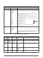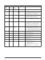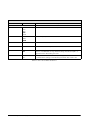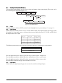
1
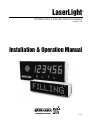
LaserLight
®
M-Series and 4-SG LED Remote Displays
Version 2.05
Installation & Operation Manual
75936
Contents
1.0
Introduction.................................................................................................................................. 1
1.1 Annunciators . . . . . . . . . . . . . . . . . . . . . . . . . . . . . . . . . . . . . . . . . . . . . . . . . . . . . . . . . . . . . . . . . . . 2
2.0
Mounting Plate Installation and Setup ........................................................................................ 3
2.1
2.2
2.3
2.4
3.0
Unpacking and Assembly . . . . . . . . . . . . . . . . . . . . . . . . . . . . . . . . . . . . . . . . . . . . . . . . . . . . . . . . . .
Enclosure Disassembly. . . . . . . . . . . . . . . . . . . . . . . . . . . . . . . . . . . . . . . . . . . . . . . . . . . . . . . . . . . .
Wall Mounting . . . . . . . . . . . . . . . . . . . . . . . . . . . . . . . . . . . . . . . . . . . . . . . . . . . . . . . . . . . . . . . . . .
Wiring. . . . . . . . . . . . . . . . . . . . . . . . . . . . . . . . . . . . . . . . . . . . . . . . . . . . . . . . . . . . . . . . . . . . . . . . .
3
3
4
4
2.4.1
2.4.2
2.4.3
2.4.4
2.4.5
2.4.6
2.4.7
2.4.8
5
6
8
8
8
9
9
9
AC Wiring . . . . . . . . . . . . . . . . . . . . . . . . . . . . . . . . . . . . . . . . . . . . . . . . . . . . . . . . . . . . . . . . . . . . . . .
Serial Wiring . . . . . . . . . . . . . . . . . . . . . . . . . . . . . . . . . . . . . . . . . . . . . . . . . . . . . . . . . . . . . . . . . . . . .
20 mA Current Loop . . . . . . . . . . . . . . . . . . . . . . . . . . . . . . . . . . . . . . . . . . . . . . . . . . . . . . . . . . . . . . .
RS-232 . . . . . . . . . . . . . . . . . . . . . . . . . . . . . . . . . . . . . . . . . . . . . . . . . . . . . . . . . . . . . . . . . . . . . . . . .
RS-485 . . . . . . . . . . . . . . . . . . . . . . . . . . . . . . . . . . . . . . . . . . . . . . . . . . . . . . . . . . . . . . . . . . . . . . . . .
Reset Switch . . . . . . . . . . . . . . . . . . . . . . . . . . . . . . . . . . . . . . . . . . . . . . . . . . . . . . . . . . . . . . . . . . . . .
Communicating with Indicators and LEDs . . . . . . . . . . . . . . . . . . . . . . . . . . . . . . . . . . . . . . . . . . . . . . .
Decimal Point (7-Segment Display) . . . . . . . . . . . . . . . . . . . . . . . . . . . . . . . . . . . . . . . . . . . . . . . . . . . .
Configuration ............................................................................................................................ 10
3.1
3.2
3.3
3.4
Auto-Learn . . . . . . . . . . . . . . . . . . . . . . . . . . . . . . . . . . . . . . . . . . . . . . . . . . . . . . . . . . . . . . . . . . . .
Manual Configuration . . . . . . . . . . . . . . . . . . . . . . . . . . . . . . . . . . . . . . . . . . . . . . . . . . . . . . . . . . . .
Serial Communications. . . . . . . . . . . . . . . . . . . . . . . . . . . . . . . . . . . . . . . . . . . . . . . . . . . . . . . . . . .
Testing the Remote Display . . . . . . . . . . . . . . . . . . . . . . . . . . . . . . . . . . . . . . . . . . . . . . . . . . . . . . .
10
10
14
19
3.4.1
3.4.2
3.4.3
3.4.4
19
19
19
20
Display . . . . . . . . . . . . . . . . . . . . . . . . . . . . . . . . . . . . . . . . . . . . . . . . . . . . . . . . . . . . . . . . . . . . . . . .
Digital Outputs . . . . . . . . . . . . . . . . . . . . . . . . . . . . . . . . . . . . . . . . . . . . . . . . . . . . . . . . . . . . . . . . . .
Digital Inputs . . . . . . . . . . . . . . . . . . . . . . . . . . . . . . . . . . . . . . . . . . . . . . . . . . . . . . . . . . . . . . . . . . . .
Loop Back . . . . . . . . . . . . . . . . . . . . . . . . . . . . . . . . . . . . . . . . . . . . . . . . . . . . . . . . . . . . . . . . . . . . .
3.5 Version . . . . . . . . . . . . . . . . . . . . . . . . . . . . . . . . . . . . . . . . . . . . . . . . . . . . . . . . . . . . . . . . . . . . . . . 20
3.6 Demand Print Displaying . . . . . . . . . . . . . . . . . . . . . . . . . . . . . . . . . . . . . . . . . . . . . . . . . . . . . . . . . 20
3.7 Serial Commands. . . . . . . . . . . . . . . . . . . . . . . . . . . . . . . . . . . . . . . . . . . . . . . . . . . . . . . . . . . . . . . 20
3.7.1
3.7.2
3.7.3
4.0
Options ....................................................................................................................................... 24
4.1
4.2
4.3
4.4
4.5
Time and Date . . . . . . . . . . . . . . . . . . . . . . . . . . . . . . . . . . . . . . . . . . . . . . . . . . . . . . . . . . . . . . . . .
Temperature. . . . . . . . . . . . . . . . . . . . . . . . . . . . . . . . . . . . . . . . . . . . . . . . . . . . . . . . . . . . . . . . . . .
Visor Installation . . . . . . . . . . . . . . . . . . . . . . . . . . . . . . . . . . . . . . . . . . . . . . . . . . . . . . . . . . . . . . . .
Pole Mount Kit . . . . . . . . . . . . . . . . . . . . . . . . . . . . . . . . . . . . . . . . . . . . . . . . . . . . . . . . . . . . . . . . .
Traffic Light Option . . . . . . . . . . . . . . . . . . . . . . . . . . . . . . . . . . . . . . . . . . . . . . . . . . . . . . . . . . . . . .
4.5.1
4.5.2
4.5.3
5.0
Command Format (7-Segment): . . . . . . . . . . . . . . . . . . . . . . . . . . . . . . . . . . . . . . . . . . . . . . . . . . . . . 21
Display Message Command Format (Matrix Display): . . . . . . . . . . . . . . . . . . . . . . . . . . . . . . . . . . . . . 22
Set or Get the Digital I/O . . . . . . . . . . . . . . . . . . . . . . . . . . . . . . . . . . . . . . . . . . . . . . . . . . . . . . . . . . . 23
24
24
24
25
27
Dry Contact Wiring . . . . . . . . . . . . . . . . . . . . . . . . . . . . . . . . . . . . . . . . . . . . . . . . . . . . . . . . . . . . . . . 27
Single Switch Wiring . . . . . . . . . . . . . . . . . . . . . . . . . . . . . . . . . . . . . . . . . . . . . . . . . . . . . . . . . . . . . . 28
Two Switch Wiring . . . . . . . . . . . . . . . . . . . . . . . . . . . . . . . . . . . . . . . . . . . . . . . . . . . . . . . . . . . . . . . 28
Appendix .................................................................................................................................... 29
5.1
5.2
5.3
5.4
5.5
5.6
Error Messages . . . . . . . . . . . . . . . . . . . . . . . . . . . . . . . . . . . . . . . . . . . . . . . . . . . . . . . . . . . . . . . .
7-Segment Display Replacement Parts . . . . . . . . . . . . . . . . . . . . . . . . . . . . . . . . . . . . . . . . . . . . . .
8- & 12-Character Display Replacement Parts . . . . . . . . . . . . . . . . . . . . . . . . . . . . . . . . . . . . . . . . .
LaserLight Remote Display Enclosure Dimensions . . . . . . . . . . . . . . . . . . . . . . . . . . . . . . . . . . . . . .
LaserLight Matrix Display Enclosure Dimensions . . . . . . . . . . . . . . . . . . . . . . . . . . . . . . . . . . . . . . .
Specifications . . . . . . . . . . . . . . . . . . . . . . . . . . . . . . . . . . . . . . . . . . . . . . . . . . . . . . . . . . . . . . . . . .
29
29
34
38
39
40
Technical training seminars are available through Rice Lake Weighing Systems.
Course descriptions and dates can be viewed at www.ricelake.com or obtained
by calling 715-234-9171 and asking for the training department.
© 2008 Rice Lake Weighing Systems. All rights reserved. Printed in the United States of America.
Specifications subject to change without notice. Version 2.05
March 2008
About This Manual
This manual is intended for use by service technicians
responsible for installing and servicing the
LaserLight® LED remote display.
Installation procedures are presented in the order
likely to be followed by the installer: pre-installation
setup, configuration, and on-site installation.
1.0
Caution
Most procedures described in this
manual require work inside the remote
display enclosure. These procedures
are to be performed by qualified
service personnel only.
Authorized distributors and their employees
can view or download this manual from the
Rice Lake Weighing Systems distributor
site at www.ricelake.com.
Introduction
The LaserLight remote display features a super-bright LED display and non-glare filtered lens for use in a wide
variety of applications. The LaserLight M-Series and LaserLight 4-SG Series are available with a 7-segment,
six-digit display or an 8- or 12-character matrix display. The LaserLight remote display is designed to work with
most digital weight indicators, host computers, and peripherals using 20 mA current loop, RS-232, or RS-485
communications.
The unique IntelliBright™ feature uses a photo sensor to read ambient light and automatically adjusts the
LaserLight display between day and night settings.
The display has seven internal buttons and three external buttons to set various parameters. The external buttons
include two for setting the time and date, and one for the learn sequence. The configuration menu is entered via
the setup button and is displayed on the display board panel for easy configuration of the unit.
This manual provides installation and configuration instructions for the display.
Standard Features
The LaserLight 7-segment remote display is available in 4" or 6" digit sizes and the matrix display is available in
2.5" character size with 8 or 12 positions. The LaserLight 4-SG remote display comes in a 4" digit size in a 6"
enclosure size. Both styles use an Auto-Learn function which automatically determines the serial settings and
data format used by the attached indicator.
Additional standard features include:
• Hold displayed weight (demand input)
• Adjustable daylight/night intensity
• Mirror function (weight only)
• Auto-sensing 115/230 VAC power supply
• Mode and unit legends
• Echo
• Traffic light option (4" digit size only)
Optional Features
Optional features of the LaserLight remote display include:
• Temperature
• Time and date
• Field-installable metal visor for all models
• Interchangeable mounting bracket adapter plate
Introduction
1
1.1
Annunciators
The 7-segment LaserLight remote display uses a set of four high-intensity LED annunciators (shown in
Figure 1-1) and the matrix display uses two positions of the display to show arrows (shown in Figure 1-2) which
provide additional information about the value being displayed:
• Gross and Net annunciators are lit to show whether the displayed weight is a gross or net weight.
• lb, kg annunciators indicate the units associated with the displayed value and represent primary and
secondary units.
• Red, green circle and green arrow annunciators indicate the traffic light state on the display. This feature
applies to only the LaserLight 4-SG.
Optional traffic
light display
LED
annunciators
Figure 1-1. 7-Segment Front Panel Display
Arrow
annunciators
Figure 1-2. Matrix Display Front Panel
2
LaserLight Remote Display Installation & Operation Manual
2.0
Mounting Plate Installation and Setup
The LaserLight remote display can be easily set up and configured once mounted to a wall or pole. This section
describes basic installation, AC wiring, RS-232, RS-485, and 20 mA current loop connections. Once installation
setup is complete, go to Section 3.0 for information on configuring the remote display.
Caution
Use a wrist strap to ground yourself and protect components from electrostatic discharge (ESD) when working inside the
enclosure.
This unit uses double pole/neutral fusing which could create an electric shock hazard. Procedures requiring work inside the
remote display must be performed by qualified service personnel only.
Warning
The LaserLight has no on/off switch. before opening the unit, ensure the power cord is disconnected from the power outlet.
2.1
Unpacking and Assembly
Immediately after unpacking, visually inspect the LaserLight remote display for damage. If any parts were
damaged in shipment, notify Rice Lake Weighing Systems and the shipper immediately. The shipping carton
contains the remote display and this manual. The main components of the LaserLight remote display include:
• Painted steel enclosure
• Primary and secondary display boards
• Power supply
• Mounting panel for the CPU board (located on back of mounting plate)
Primary display
Secondary display
Figure 2-1. Mounting Plate Showing Primary / Secondary Display Boards (7-Segment Display)
2.2
Enclosure Disassembly
For ease of installation, remove the mounting plate (which includes the primary and secondary display boards)
before installing the LaserLight remote display. This protects the LEDs from unnecessary jarring and makes the
enclosure lighter for installation. Use the following steps to remove the mounting plate from the enclosure.
Caution
Use caution when lowering or raising the mounting plate to ensure the LEDs do not touch the enclosure. If
any of the LEDs get bent, they can be straightened back into position.
1. Remove the captive screws located on the bottom of the enclosure. The mounting plate is located on the
inside of the enclosure. It is mounted on a frame that can be held in place by tabs and two pins, (located
on the inside of the enclosure, shown in Figure 2-2).
2. Glide the mounting plate frame downward so that it hangs freely beneath the enclosure.
3. Disconnect the chassis ground wire from the top of the mounting plate mounting frame.
Mounting Plate Installation and Setup
3
4. Disconnect the AC cord assembly from the power supply.
5. Using a slight diagonal twisting motion, slide the mounting plate out from the inside of the enclosure and
set it aside.
Figure 2-2. Tab Pin Assembly on Inside of Remote Display Enclosure
2.3
Wall Mounting
The LaserLight remote display can be mounted to any vertical surface or pole.
Select a site and use installation screws or wall anchors to secure the remote display to a wall. If installing the
remote display on a pole, an optional pole mounting kit is required, this kit fits 4" - 8" poles. Once the enclosure
is secured, slide the mounting plate down so that it is hanging freely from the enclosure with the tabs secured
against the pins. This enables the user to continue wiring the remote display.
2.4
Wiring
The LaserLight remote display provides three cord grips located on the underside of the enclosure for cabling;
one for the power cord (cord supplied), and two for serial communications. The LaserLight remote display is
pre-wired. Ribbon cables connect the CPU board to the digit display boards. An A/C power cord is also supplied.
Only the serial communications cable must be connected. Use the following steps to wire the remote display.
Warning
The LaserLight remote display has no on/off switch. Before opening the unit, ensure the power cord is
disconnected from the power outlet.
1. If the remote display is not open, remove the captive screws located on the bottom of the remote display
enclosure.
2. Lower the mounting plate from the inside of the enclosure.
Caution
Use caution when lowering or raising the mounting plate to ensure the LEDs do not touch the enclosure sides.
If any of the LEDs get bent, they can be straightened back into position.
3. Loosen the retaining screws located on the front of mounting plate (Figure 2-3). The mounting plate is
hinged on a backplate frame to allow easier access to the AC wiring and the CPU board.
Retaining screw
Figure 2-3. Retaining Screw Location
4
LaserLight Remote Display Installation & Operation Manual
2.4.1
AC Wiring
The LaserLight power supply can run on either 115 or 230 VAC. The AC wiring is run through the cord grip to a
3-position AC terminal block bracket on the inside of the enclosure (shown in Figure 2-4). This bracket can be
removed by loosening the two standoffs and lifting it off. It can then be lowered and pulled outside of the
enclosure to ease wiring connections.
Grounding stud
Figure 2-4. Inside Enclosure Backplate Diagram
Wiring is run from the terminal block down to the power supply on the back of the mounting plate (location
shown in Figure 2-5).
J8
HS1
R
E
C
V
PAS
ACT
RX0_485
TX0_485
TX1 RX1_20MA
RX1_232
TX1_20MA
RX0_20MA
TX1_232
TEST
CPU +5V
1
POWER
SUPPLY
VR4
RESET
J3
U7
RX0
TX0
HI
GND
VR3
TEST +12V
RX1
HCPL4100
TRIPSET
TX0_232
MX3
TEST
MX3 +5V
HS2
T
20mA
RX0_232
VR2
M
1
MX2
J4
I
PAS
ACT
1
1
1
J7
ISP
VR1
J5
J6
1
1
1
1
X
MX1
1
1
J9
1
Power supply
CONNECTOR GUIDE
M
J1 - DIGITAL I/O - FUTURE USE
J2 - FIBER LINK OPTION CARD
J3 - POWER SUPPLY INPUT
J4 - TEMPERATURE PROBE
J5 - LEARN SWITCH
J6 - 20mA SERIAL
J7 - TIME SET
J8 - RS-232 SERIAL
J9 - RS-485 SERIAL
KP1 - KEYPAD
0
1
LO D
KP1
J2
1
RICE LAKE WEIGHING SYSTEMS
Assembly P/N
Revision
2002
C1
C5
1
DP2
DP1
J1
1
1
DP3
Figure 2-5. Mounting Plate Diagram with CPU Board and Power Supply Locations
NOTE:
Pin 1 is positioned at the left end of the connectors. See Figure 2-5 above.
Refer to the following table for AC wiring connections.
3-pin Terminal Block on Enclosure Back
To Power Supply
Pin
Wire
Color
Pin
1
Hot
Brown
1
2
Neutral
Blue
2
3
Ground
Green
Ground Tab
Table 2-1. AC Wiring Connections
Note: Ensure that a ground wire is attached to the grounding stud located on the enclosure backplate (see Figure 2-4).
Mounting Plate Installation and Setup
5
2.4.2
Serial Wiring
Serial communications are connected to the CPU board using removable screw terminal plugs on J6, J8 and J9
(see Figure 2-8).
To connect the communications cable to the remote display, do the following:
1. If the enclosure is not open, disconnect power and open the remote display by removing the captive
screws on the bottom of the enclosure and lower the mounting plate.
2. Open the captive retaining screws (Figure 2-6) and flip forward the hinged mounting plate.
Captive retaining
screw
Figure 2-6. LED Primary and Secondary Display Boards (7-Segment Display)
3. Loosen the serial cable cord grip and push enough communications cable into the enclosure to allow
attachment to the CPU board.
4. Strip 1/4" (.65 cm) of insulation from the serial cable ends.
5. Make cable connections for RS-232, RS-485, or 20 mA current loop communications as described in
Table 2-2.
6. Remove any excess cable from inside the enclosure. Tighten the serial cable cord grip.
NOTE: If you are experiencing RF Interference, follow the instructions below.
1. Loop the serial wires through the cylindrical ferrite (PN 66730) provided with this manual. See
Figure 2-7 below.
2. Using the plastic cable ties provided, secure the wires to the ferrite and the serial cable to the learn switch
wires to keep ferrite from contacting the CPU board. See Figure 2-7 below.
Cylindrical
ferrite
Plastic cable ties
Figure 2-7. Cylindrical Ferrite Placement
6
LaserLight Remote Display Installation & Operation Manual
Connector
Pin Assignment
J1
1
Ground
2
Digin 0
3
Digin 1
4
+ 5 Volts
5
DigOut 0
6
DigOut 1
7
Ground
1
20 mA Rx+
Port 0
2
20 mA Rx–
Port 0
3
20 mA Tx+
Port 1
4
20 mA Tx–
Port 1
1
RS-232 TxD 0
Port 0
2
RS-232 TxD 1
Port 1
3
RS-232 RxD 0
Port 0
4
RS-232 RxD 1
Port 1
5
RS-232 SIG GND
6
RS-232 SIG GND
1
RS-485 Rx+
Port 0
2
RS-485 Rx–
Port 0
3
RS-485 Tx+
Port 0
4
RS-485 Tx–
Port 0
J6
J8
J9
Function
Port Position
Table 2-2. Serial Communications Wiring
NOTES:
•Terminals J6, J8, and J9 are removable screw terminal plugs.
•Port 0 is used for input only and port 1 is used to drive the next LaserLight Remote Display. See Table 2-2
above.
Mounting Plate Installation and Setup
7
Figure 2-8 shows the LaserLight remote display CPU board.
J8
J7
ISP
VR1
PAS
ACT
HS1
R
E
C
V
PAS
ACT
RX0_485
TX0_485
TX1 RX1_20MA
RX1_232
TX1_20MA
RX0_20MA
TX1_232
VR3
TEST +12V
HS2
T
MX3
TEST
MX3 +5V
TEST
CPU +5V
RX1
POWER
SUPPLY
VR4
HCPL4100
TRIPSET
TX0_232
VR2
M
1
MX2
J4
20mA
RX0_232
1
1
1
I
1
J5
J6
1
1
1
X
MX1
1
1
J9
1
RESET
J3
U7
RX0
TX0
HI
CONNECTOR GUIDE
M
J1 - DIGITAL I/O - FUTURE USE
J2 - FIBER LINK OPTION CARD
J3 - POWER SUPPLY INPUT
J4 - TEMPERATURE PROBE
J5 - LEARN SWITCH
J6 - 20mA SERIAL
J7 - TIME SET
J8 - RS-232 SERIAL
J9 - RS-485 SERIAL
KP1 - KEYPAD
0
1
LO D
KP1
J2
2002
1
RICE LAKE WEIGHING SYSTEMS
Assembly P/N
Revision
C1
C5
DP1
1
DP2
1
J1
1
DP3
Figure 2-8. LaserLight Remote Display CPU Board
Port 0 which is connected to the indicator supports three configurations; 20 mA, RS-232, and RS-485
communications. Port 1 which is the Echo port, supports 20 mA and RS-232 communications.
2.4.3
20 mA Current Loop
The 20 mA current loop communication is provided on connector J6 of the CPU board (Figure 2-8,Table 2-2).
Ensure receive jumpers are across RX0, 20 mA and select active or passive switch settings. Remove any unused
jumpers. (Figure 2-9)
2.4.4
RS-232
The RS-232 connection is provided on connector J8 of the CPU board (Figure 2-8,Table 2-2). Ensure the
transmit and receive jumpers are across TX0 232 and RX0 232. (Figure 2-9)
2.4.5
RS-485
The RS-485 connection is provided on connector J9 of the CPU board (Figure 2-8,Table 2-2). Ensure the
transmit and receive jumpers are across TX0 485 and RX0 485. (Figure 2-9)
Port 1
Jumpers
Port 0 Jumpers
Reset Switch
Signal LED’s
Signal LED’s
20 mA
Active/Passive
Figure 2-9. Jumper Pin Locations
8
LaserLight Remote Display Installation & Operation Manual
2.4.6
Reset Switch
The reset switch enables a simulated power up reset. It then goes back to normal operation mode. The reset
switch eliminates having to unplug the unit to do a reset. Refer to Figure 2-8 on page 7 for the reset switch
location on the CPU board.
2.4.7
Communicating with Indicators and LEDs
Small LEDs located on the CPU board flash when serial data is received or sent. The transmit indicators flash
when data is being sent out of the port. The receive indicator flashes when the data is received. A steady indicator
on any receive LED reflects a connection with no streaming data. See to Figure 2-9 on page 7 for communication
indicator locations on the CPU board.
2.4.8
Decimal Point (7-Segment Display)
The primary display board has decimal LED’s. These can be changed to commas by moving a jumper located on
the front of the display board shown in Figure 3-2 on page 10.
Ensure that the decimal point/comma jumper is in the proper position on the display board.
Mounting Plate Installation and Setup
9
3.0
Configuration
Once the LaserLight remote display is installed, it may need to be configured if your indicator requires special
settings. This can be done manually and is explained in Section 3.2.
Using Auto-Learn (Section 3.1) simplifies installation by automatically detecting the communications format
and data rate used by the indicator and eliminates the need for configuration.
3.1
Auto-Learn
The LaserLight remote display incorporates a software feature called Auto-Learn. Auto-Learn examines the
serial data stream sent from the attached indicator and attempts to determine the data settings and format used by
the indicator.
Auto-Learn occurs automatically when Port 0 is not locked via software configuration (not locked by default)
(Table 3-5), and the connecting indicator is configured to send continuous (streaming) data. It will also occur
automatically if the currently streamed format changes. LaserLight will Auto-Learn by itself in most cases. Or,
you can force this by pressing the external Auto-Learn button.
Use the following quick steps for Auto-Learn.
1. Open the enclosure per disassembly instructions in Section 2.2 on page 3 and connect the serial
interface.
2. Visually inspect that the Auto-Learn button is connected to J5 on the CPU board (see Figure 3-1 for
plug-in location).
3. Power up the remote display.
4. Momentarily press the Learn button.
5. Use the right and left buttons to shift the displayed data string if the displayed weight is not positioned
with LSD.
NOTES:
• If you are using an indicator with a Toledo T8142 format, follow steps 1 through 5 and then go to SP IND
in the serial menu. Select 1 under special indicators.
• It is recommended to lock Port 0 (see Table 3-5), to eliminate any un-intentional changes from occurring.
3.2
Manual Configuration
To begin configuration, open the enclosure (See Section 2.2 on page 3 for enclosure disassembly instructions), to
access the CPU board (Figure 3-1) and digit display board (Figure 3-2).
J8
ACT
HS1
R
E
C
V
PAS
ACT
RX0_485
TX0_485
RX1_232
TX1_20MA
RX0_20MA
TX1_232
TEST +12V
POWER
SUPPLY
VR4
RESET
J3
U7
RX0
TX0
HI
CONNECTOR GUIDE
M
J1 - DIGITAL I/O - FUTURE USE
J2 - FIBER LINK OPTION CARD
J3 - POWER SUPPLY INPUT
J4 - TEMPERATURE PROBE
J5 - LEARN SWITCH
J6 - 20mA SERIAL
J7 - TIME SET
J8 - RS-232 SERIAL
J9 - RS-485 SERIAL
KP1 - KEYPAD
0
1
LO D
KP1
J2
2002
1
RICE LAKE WEIGHING SYSTEMS
Assembly P/N
Revision
C1
C5
DP1
1
DP2
1
Figure 3-1. LaserLight CPU Board
10
VR3
TEST
CPU +5V
RX1
HCPL4100
TRIPSET
TX1 RX1_20MA
MX3
TEST
MX3 +5V
HS2
T
20mA
TX0_232
VR2
M
1
MX2
J4
I
PAS
1
1
1
J7
ISP
VR1
RX0_232
J5
J6
1
1
1
1
X
MX1
1
1
J9
1
LaserLight Remote Display Installation & Operation Manual
J1
1
DP3
The setup button is located on the secondary display board (Figure 3-2).
Jumper position
for decimal point or
comma
Setup button
Figure 3-2. Setup Button Location on Secondary Display Board (7-Segment Display)
The display board is mounted on a hinged mounting plate to allow for easy access to the CPU board. Press the
SETUP button (shown in Figure 3-2) to access main menu configuration parameters.
Main menu parameters include:
• Configuration
• Serial communications
• Test
• Version
The LaserLight remote display can be configured and displayed using a series of menus accessed using internal
buttons located on the secondary display and shown in Figure 3-3.
SETUP
UP
LEFT
ENTER
RIGHT
DOWN
Figure 3-3. Configuration Setup Buttons
Use the UP/DOWN, LEFT/RIGHT buttons to navigate through menu items and the ENTER button for setting a
selection.
Configuration
11
Table 3-1 summarizes the functions of each of the main menus and Figure 3-4 illustrates the main menu
selections.
7-segment
Display Menu
8-Character
Matrix Display
Menu
12-Character
Matrix Display
Menu
CONFIG
CONFIG
CONFIG
Configuration. Configures time and date (option), temperature (option),
display brightness, mirroring, and other parameters associated with
configuring the remote display
SERIAL
SERIAL
SERIAL
Serial. Configures serial ports
Test. System hardware tests
TEST
TEST
TEST
VER
VERSION
VERSION
Menu Function
Version. Displays installed software version number
Table 3-1. LaserLight Remote Display Menu Summary
TEST
SERIAL
CONFIG
VER
Figure 3-4. LaserLight Main Menu Options
When configuring the indicator attached to the remote display, ensure that the decimal point configuration is
compatible with the remote display. The LaserLight 7-segment remote display allows none, one, or two decimal
places (see Figure 3-2 for jumper positions). The 8- or 12-character matrix displays use one character position for
the decimal point.
Figure 3-5 shows the configuration menu.
CONFIG
SERIAL
TEST
VER
LEARN EN
TIM DAT
On
ENABLE
FORMAT
SET
DATE
On
USA
ISO
Hour
Minutes
Off
Off
MIRROR
TEMP ADJ
BRIGHT
F
+/- 5
DAY
NIGHT
1
1
C
Off
SUPP 0
TEMP
2
2
Month
3
3
Day
4
4
Year
5
5
6
6
7
7
8
9
8
9
10
10
On
STDSTL
ADDRES
0 - 31
Off
On
On
On
Off
Off
MSG TM
D TEST
RESET
5 sec
On
Reset
15 sec
30 sec
Off
1 min
5 min
Figure 3-5. Configuration Main Menu Choices
Note: With the 8- and 12-character matrix displays some of the labels are not shortened, for example STDSTL in the
7-segment is STAND STILL on the 12-character display.
12
LaserLight Remote Display Installation & Operation Manual
CONFIG Menu
7-Segment Display
Parameter
8-Character Matrix 12-Character matrix
Display
Display
Choices
Description
Level 2 Submenus
TIMDAT
TIMEDATE
TIME/DATE
Enabled
Format
Set
Date
To enable time and date
Displays USA or ISO time format
Sets hours/minutes and month/day/year
Can disable date
TEMP
TEMP
TEMPERATURE
F
C
Select Fahrenheit or Celsius
TEMPADJ
TEMPADJ
DEGREE ADJUST
+ 5%
- 5%
+/- 5 degrees display. Can add or subtract up to +/- 5
degrees of both Fahrenheit or Celsius
BRIGHT
BRIGHT
BRIGHTNESS
Day
Night
Selects the brightness during day or nightime hours
SUPP O
SUPP O
SUPPRESS 0
On
Off
Select On to enable the suppression of leading zeros
in a weight.
MIRROR
MIRROR
MIRROR
On
Off
Select On to display LED readout in reverse. The
menu is viewed normally.
STDSTL
STD STL
STAND STILL
On
Off
Select On to enable display updated weight only when
the scale is not in motion.
ADDRES
ADDRESS
ADDRESS
0 through
31
Assign a command address by selecting a number
between 0-31.
MSG TM
MSG TIME
MESSAGE TIME
5, 15, 30
sec., 1, 5
minutes
Select amount of time a message stays on the remote
display. Time can vary from 5 seconds to 5 minutes. If
no serial command is used, then this parameter is not
used. (7-segment DM command only)
D TEST
DSP TEST
DISPLAY TEST
On
Off
Set this parameter On to enable a countdown display
test on start up.
RESET
RESET
RESET CONFIG
LEARN EN
LEARN EN
LEARN EN
Resets the remote display to default parameters
On
Off
Enable allows weight learn operation. With Learn off,
the unit operates for demand messages.
Table 3-2. Configuration Menu Summary - Level 2
Configuration
13
Parameter
Choices
Description
Level 3 submenus (TIMDAT Parameter)
ENABLE
On
Off
Select On to enable time and date option. Note: You need an additional chip
called a “snap hat.” It is recommended that you disable the time/date feature if
you don’t want this addtional chip. Will display at zero or less weight only.
FORMAT
USA
ISO
Displays in either USA or ISO (military time) format
SET
HH/MM
MM/DD/YYYY
Sets hour/minutes and month/day/year
DATE
On
Off
Select Off to disable the date display if the date and time option is installed. Time
is still displayed.
Brightness (BRIGHT Parameter)
DAY
1-10
Selects the brightness during day. Brightness is set from 1-10 or 10 to 100% of
the full brightness. IntelliBright averages measured ambient light over a ten
minute time span.
NIGHT
1-5-10
Selects the brightness during night. Brightness is set from 1-10 or 10 to 100% of
the full brightness. IntelliBright averages measured ambient light over a ten
minute time span.
Table 3-3. Configuration Menu Summary - Level 3
3.3
Serial Communications
The LaserLight remote display has two serial ports available:
• Port 0 - Provides communication with the indicator
• Port 1 - Provides echoing OF INDICATOR DATA
There are 15 sub-parameters associated with Port 0 and six sub-parameters associated with Port 1 which are
shown in Figure 3-6 on page 15. See Section 2.4.2 for serial wiring positions.
14
LaserLight Remote Display Installation & Operation Manual
CONFIG
PORT0
SERIAL
TEST
VER
PORT1
BAUD
PARITY
DATA
STOP
ECHO
LOCK
1200
Odd
7
1
On
Off
2400
Even
8
2
Off
On
4800
None
9600
19200
BAUD
PARITY
DATA
STOP
HOLD WT
LOCK
E CHAR
1200
Odd
7
1
On
On
CR
2400
Even
8
2
Off
Off
LR
4800
None
LW POS
number
between 5-50
FF
9600
ETX
19200
LENGTH
number
number
between
between 5-75
5-75
PRIMU
A -Z
SECU
GROSSC
NETC
MOTION
A -Z
A -Z
A -Z
A -Z
SP IN D
0
1
2
3
4
5
Figure 3-6. Serial Menu
Configuration
15
Serial Menu
Parameter
Choices
Description
Level 2 Submenus
Port 0
BAUD
PARITY
DATA BITS
STOP BITS
HOLD WT
Configure Port 0. See Level 3 submenu parameter descriptions.
Keeps last weight displayed if communication is lost and prevents the remote
display from going into an error condition.
If enabled, prevents the Auto-Learn (Section 3.1) parameter from working
and ensures settings remain currently set.
This feature looks at the last character to determine the end of a packet.
Can select a number between 5 and 50. Is zero indexed and determines last
weight position of the format.
Can select a number between 5 and 75 and determines the length of packet
in the string format.
Select primary unit characters
If selected, the
Select secondary unit characters
appropriate
Select gross character
annunciator is
Select net character
lit
Select motion status character
Select, decode status, and settings for special indicator type.
0 = none
1 = Toledo 8142 format
LOCK
E CHAR
LW POS
LENGTH
PRIM U
SEC U
GROS C
NET C
MOTION
SP IND
PORT 1
BAUD
PARITY
DATA BITS
STOP BITS
ECHO
Configure Port 1. See level 3 submenu parameter descriptions.
Disable this to allow echoing between remote display and other devices. Data
settings should be set equal to or greater than device being echoed to.
If disabled, remote display uses same settings as indicator after an
Auto-Learn.
LOCK
Table 3-4. Serial Communication Menu Summary
Serial Menu
Port 0
Parameter
Choices
Description
Level 3 Submenus
7-Segment
Display
Parameters
8-Character
Display
Parameters
12-Character
Display
Parameters
BAUD
BAUD
BAUD
1200
2400
4800
9600
19200
Baud rate. Selects the transmission speed for Port 0
PARITY
PARITY
PARITY
ODD
EVEN
NONE
Selects the parity of data of Port 0
DATA
DATABITS
DATA BITS
7
8
Selects the number of data bits of Port 0
Table 3-5. Port 0 Serial Menu
16
LaserLight Remote Display Installation & Operation Manual
Serial Menu
7-Segment
Display
Parameters
8-Character
Display
Parameters
12-Character
Display
Parameters
STOP
STOPBITS
STOP BITS
1
2
Selects the number of stop bits of Port 0
HOLD WT
HOLD WT
HOLD WEIGHT
ON
OFF
Select On to enable this feature to keep the last
weight displayed if communication is lost or you are
using demand updated weight and prevents remote
display from going into an error condition.
LOCK
LOCK
LOCK
ON
OFF
Select On to make sure the current settings don’t get
changed and to disable Auto-Learn. When off, the
system enables the Auto-Learn function.
E CHAR
END CHAR
END CHAR
CR
LR
FF
ETX
When Auto-Learn is enabled, this feature looks at the
last character to determine the end of a packet.
LW POS
L WT POS
LAST WT POS
5 - 50
Select a number between 5 and 50 to determine the
last weight position. If setting up Port 0 manually, the
last weight position is zero indexed. Example:
<STX>123456<CR> where <STX> is the start of the
text character, and <CR> is a carriage return
character, the “6” is in the 6th position, not the 7th.
LENGTH
LENGTH
LENGTH
5-75
Select a number between 5 and 75 to determine the
length of the packet in the string format.
Formats such as Toledo 8142 end in CR<AA> where
<AA> is a 2-byte checksum, the checksum should
not be counted when calculating the format length.
PRIM U
PRIM UNT
PRIM UNITS
A-Z
Select a primary display character from A-Z. If
selected, annunciator is lit
SECD U
SECD UNT
SECD UNITS
A-Z
Select a secondary display character from A-Z. If
selected, annunciator is lit
GROS C
GROSS CH
GROSS CHAR
A-Z
Select a gross character character from A-Z. If
selected, annunciator is lit
NET C
NET CHAR
NET CHAR
A-Z
Select a net character character from A-Z. If selected,
annunciator is lit
MOTION
MOTION
MOTION
A-Z
Select a motion display character from A-Z. If
selected, annunciator is lit
SP IND
SP IND
SPECIAL IND
1, 2, 3, 4
1 - Toledo 8142 format bit-mapped status data
2 - Inclinometer custom program
3 - Flex-Weigh DWM IV
4 - Fairbanks 2500/and 9401 compatible units
5 - AnD 4323
0 - Off (Select when not using a special indicator)
Table 3-5. Port 0 Serial Menu (Continued)
Configuration
17
Serial Menu
Port 1 Parameter
Choices
Description
Level 3 submenus
BAUD
1200
2400
4800
9600
19200
Baud rate. Selects the transmission speed for Port 1
PARITY
ODD
EVEN
NONE
Selects the parity of data transmitted from Port 1
DATA BITS
7
8
Selects the number of data bits transmitted from Port 1
STOP BITS
1
2
Selects the number of stop bits transmitted from Port 1
ECHO
ON
OFF
Enable this feature to allow echoing between the remote display and other
devices. If enabled and echoing, the baud settings must be set equal to or
greater than the device being echoed to.
LOCK
OFF
ON
If this parameter is disabled, the echo port display uses the same
communications settings as the indicator port after an Auto-Learn is run.
Table 3-6. Port 1 Serial Menu Parameters
18
LaserLight Remote Display Installation & Operation Manual
3.4
Testing the Remote Display
The LaserLight remote display provides a test to check the hardware of the remote display. These tests can be
accessed through the main menu (Figure 3-7).
CONFIG
SERIAL
TEST
VER
DISPLY
DIGOUT
DIGIN
LOOP BK
XX
LL-OFF
LH-grn arrow
HL-grn circle
HH-red circle
Figure 3-7. Test Menu Choices
3.4.1
Display
When this feature is enabled, all LEDs remain lit until the ENTER button is pressed (Figure 3-2 on page 11).
3.4.2
Digital Outputs
When enabled, this feature provides a way to view the different states of the digital outputs or the stop/go option
if installed.Use left and right arrows to increment/decrement and display the states LL, LH, HL, and HH which
are digital values of the 2 ports.
Dig out 1
Dig out 0
Stop/Go Signal
L
L
L
H
Green arrow on
H
L
Green circle on
H
H
Red stop
Off
The following table lists the relay terminology and digital signal level terminology of each command.
Relay On/Off Terminology
L = ON = 0V
H = OFF = +5V
Table 3-7.
Press the right button again to display LL and the stop/go option will show no light at all.
Press the right button again to display LH and the stop/go option will show a green arrow.
Press the right button again to display HL and the stop/go option will show a green circle.
So when HH is selected, the stop/go option will show a red circle.
3.4.3
Digital Inputs
When enabled, the digital inputs displays the current values read from the digital inputs.
Configuration
19
3.4.4
Loop Back
When enabled, this feature provides a loop-back self test for use in diagnosing serial communications errors. The
loop-back self test checks the function of the remote display serial port by sending and receiving data to itself.
The following table shows the required
connections.
Port 0 TR
Port 1 RCV
Port 1 TR
Port 0 RCV
If Port 1 receives nothing from Port 0 for three seconds, the following message is displayed on the remote
display:
Fail 1
If Port 0 receives nothing from Port 1 for three seconds, the following message is displayed on the remote
display:
Fail 2
If communications are successful between the two, the following message is displayed:
Pass
3.5
Version
When Version is selected from the main menu choices (Figure 3-8), the current software version is shown on the
remote display.
CONFIG
SERIAL
TEST
VER
VERSION
Figure 3-8. Version Menu
3.6
Demand Print Displaying
The indicator and the LaserLight remote display can be set up to do a demand print display for such applications
as cattle weighing. This is useful if you want to show and keep the last weight of an animal.
Demand print display can be set up using Auto-Learn when the Port 0, Hold Weight parameter is turned On, and it
is set up manually by formatting the baud rate, data bits, parity, etc. of the remote display and the indicator.
Using Auto-Learn, ensure HOLD WT is on and continuously push the print button on the indicator to attempt a
demand print display.
3.7
Serial Commands
The LaserLight remote display has the ability to receive commands, display messages, or use a digital I/O (2
inputs & 2 outputs). When interfaced to an indicator having a configurable serial string like the IQ plus 355, 710,
800, or 810, the print ticket format can be configured to allow the user to use the Print key to send a message that
temporarily interrupts the streamed weight display. The amount of time the message is displayed is defined by
the MSG TM (message time) parameter under the CONFIG menu in the remote display, for the 7-segment remote
display.
If the LaserLight remote display is interfaced with a programmable smart indicator like the 920i, a user program
can be written to allow the user to send messages utilizing softkeys or events. When sending messages from a
user program, the user can send one message to temporarily override the streamed weight display or send
multiple messages to be displayed one at a time for several seconds each, replacing the weight display all
together if desired.
20
LaserLight Remote Display Installation & Operation Manual
The remote display also accepts serial commands to return the current time and date or to set the time and date to
a new setting. This information can be used in conjunction with user programs in the 920i to ensure the indicator
and remote display have the same time and date settings.
CONFIG
TIME/DATE
SERIAL
TEMP
TEST
VER
BRIGHT
TEMP ADJ
SUPP 0
MIRROR
STDSTL
ADDRES
0 - 31
MSG TM
5 sec
15 sec
30 sec
1 min
5 min
Figure 3-9. Assign Address and Message Timed
3.7.1
Command Format (7-Segment):
|<AA><CC><Data>!
Where:
| = Pipe character (Ox7C)
AA = Two byte address, ASCII digits (0-31)
CC = Two byte command, ASCII characters
Data = Data depending on command
! = Exclamation point character (0 x21)
Command
Description
DM
<Data> is the six charactor or less message.
Example: |00DMHELLO!
GT
Get time and date. Information gathered is sent back to the indicator so that both the remote
display and indicator match. This is not displayed on the remote display.
Example: |00GT!
ST
Set time and date. Note that two spaces are required between time and date entries.
Example: |ST08:00:00 2003-01-31!
DI
Read digital input levels (returns “0”=LL, “1”=LH, “2”=HL, “3”=HH) see Section 3.7.3
DO
Set digital output levels (“DO0”=LL, “DO1”=LH, “DO2”=HL, “DO3”=HH) see Section 3.7.3
GR
Get relay state. data=relay (ASCII charactor “0” - “1”) see Section 3.7.3
SR
Set relay state. data=relay (ASCII charactor “0” - “1”) and state (“ON = gnd, “OFF = +5V) see
Section 3.7.3
GB
Get the number of 5 x 7 Max6953 boards (0 = 7-seg, 2, 3 = 5 x 7)
GV
Get the version number
DC
Dump configuration parameters (for testing purposes only)
TP
Temperature adjustment. Allows +/- 5% degree adjustment
Time and date is sent from the remote display depending on the current remote display time and date format:
Time and date are sent to the remote display in ISO format.
USA Format: HH:MM:SS AM/PM MMM/DD/YYYY
ISO Format: HH:MM:SS YYYY-MM-DD
If the real time clock is disabled in the remote display, an error message is sent back.
Configuration
21
Example Commands and Responses:
Get time and date:
|00GT!
Get the number of 5x7 matrix boards (so, nboards x 4 = ncharacters in display):
|00GB!
Response: “OK” - success (States: DOH = DO1 = +5V) or “??” = error
Get the version number: example return “2.05”
|00GV!
Set the temperature adjustment
|00TP#!
Where # is -5 to +5 (example |00TP-1!, |00TP+3!, |00TP5) default is 0
Dump the configuration parameters (test purposes only):
|00GDC!
3.7.2
Display Message Command Format (Matrix Display):
|<AA><DM>|<Timeout>|<Flash>|<Slide On>|<Scroll>|<Scroll Count>|<Data>!
where:
| = Pipe character (0x7C)
AA = Two byte address, ASCII digits
DM = Two byte command, ASCII characters
<Display Timeout> = Milliseconds to display the message (N/A for scroll). 32.767 (32 seconds) is the maximum
timeout. Anything above that number indicates an indefinite display.
<Flash> = “Y” or “N”
<Slide On> = “Y” or “N”
<Scroll> = “Y” or “N”
<Scroll Count> = Number of times to scroll the message or “A” for annunciator msg cmd (learn enable = OFF)
<Data> = Text to display
! = Exclamation point character (0 x 21)
Command
22
Description
DM
<Data> is the 6 character message to display. If less than 6 characters, send spaces so it
equates to 6 characters. Otherwise, some data may not be overwritten.
Example: |00DMSTOP !
GT
Get time and date. Information gathered is sent back to the indicator so that both the remote
display and indicator match. This is not displayed on the remote display.
Example: |00GT!
ST
Set time and date. Note that two spaces are required between time and date entries.
Example: |ST08:00:00 2003-01-31!
DI
Get digital input state
DO
Get digital output state
GR
Get relay state. Relay 0-3, 0=Off=LL, state 1=LH, state 2=HL, state 3=On=HH.
SR
Set relay state (output relays only). Relay 0-1, state 1=On & 0=Off.
LaserLight Remote Display Installation & Operation Manual
Command
Description
GB
Get the number of 5 x 7 Max6953 boards (0 = 7-seg, 2, 3 = 5 x 7)
GV
Get the version number
DC
Dump configuration parameters (for testing purposes only)
TP
Temperature adjustment. Allows +/- 5% degree adjustment
Time and date is sent from the remote display depending on the current remote display time and date format:
Time and date are sent to the remote display in ISO format.
USA Format: HH:MM:SS AM/PM MMM/DD/YYYY
ISO Format: HH:MM:SS YYYY-MM-DD
If the real time clock is disabled in the remote display, an error message is sent back.
Examples:
Scroll the message “Rice Lake Weighing Systems” 2 times
|00DM|0|N|N|Y|2|Rice Lake Weighing Systems!
Slide on and flash the message “DRIVE AHEAD” for 5 seconds
|00DM|5000|Y|Y|N|0|DRIVE AHEAD!
3.7.3
Set or Get the Digital I/O
Notes:
Version 2.05 only accepts the serial digital I/O commands listed in this manual. All previous serial digital I/O
commands prior to Version 2.05 will not work properly with this product.
The digital outputs are set to High (OFF) on reset.
To use the two Digital Inputs and Digital Outputs, use J1 (See Figure 2-8 on page 8 ) to connect and use the
following message command formats to set or get the Digital I/O
Set Relay (set relay output 1 off)
|00SR1OFF!
Response: OK = success (State: DO1_+5V) or ?? = error
Get Digital (input) 0
|00GRO!
Response: ON = gnd or OFF = +5V
Get Digital input levels (all digin)
|00DI!
Response: 0 = LL, 1 = LH 2 = HL, 3 = HH
Set Digital output levels to HH (all digout = +5V)
|00DO3!
Response: OK = success (states: DO0=DO1=+5V) or ?? = error
Configuration
23
4.0
Options
There are several options available with the LaserLight remote display. They include:
• Time and date
• Temperature
NOTE: The Time-Date and Temperature options display in three-second cycles (along with weight) when
displayed weight is zero or below.
• Field installable visor
• Pole mount kit
• Traffic light option
4.1
Time and Date
The time and date option can be either factory installed or can be ordered at a later date. Figure 4-1 shows the
location of the time and date option.
Learn Switch
Time & Date Set
Light Probe
Membrane Vent
Temperature Probe
Figure 4-1. LaserLight Bottom Enclosure
If the time and date option (PN 75853) is added after initial installation, see Section 2.0 for enclosure
disassembly instructions. To install the this option, cut the adhesive labels from the option holes and install the
time and date switch assembly.
Attach time and date wiring to J7 on the CPU board.
4.2
Temperature
If the temperature option (PN 43412) is added after initial installation, see Section 2.0 for enclosure disassembly
instructions. To install the this option, remove the plug from the option hole and insert the temperature probe.
Attach temperature probe wiring to J4 on the CPU board.
4.3
Visor Installation
An optional visor can be installed on the LaserLight 7-segment remote display and the 8- or 12-character matrix
display. Figure 4-2 shows the remote display with the optional visor installed.
Figure 4-2. LaserLight Remote Display w/ Optional Visor Installed (7-Segment Display)
Set the visor (PN 75854 - 4" model & the 8-character matrix display) or (PN 75855 - 6" model & the
12-character matrix display) on top of the remote display and attach the visor using screws and plastic washers
provided.
24
LaserLight Remote Display Installation & Operation Manual
4.4
Pole Mount Kit
The LaserLight remote display can easily be mounted on a pole or steel I-beam using the optional pole mounting
kit (PN 75856 - 4"), (PN 77775 - 6"), (PN 85343 - 8-character), (PN 85344 - 12-character). Use the following
steps to install the pole mount option.
1. Use the enclosed 3/8" cap screws, washers ad lock nuts from the parts kit to attach the clinching pole
brackets to the pole mounting weldment.
NOTE: The 6" LaserLight remote display uses four brackets (PN 76999) and the 4", 8- & 12-character display uses two.
2. Use the enclosed 3/8-16NC bolt (PN 14747), to attach the clinching pole brackets together using washers
and lock nuts. Tighten as necessary.
3. Align the back of the LaserLight remote display to the pole mount weldment so that the holes line up.
4. Use enclosed 1/4" cap screws, washers and nuts to attach the remote display to the mounting weldment.
Reference
Number
2
Model
4"
6"
77000
76998
Description
Figure
Weldment, Pole Mounting (1)
See Figure 4-3
on page 26
8
14635
Nut, lock 1/4-20NC HEX (4)
3
14747
Bolt, 3/8-16NCx2-3/4 HEX (4" model - 1) (6" model - 2)
10
14955
Screw, cap 1/4-20NCx1/2 (4)
7
15019
Screw, cap 3/8-16NCx1 HEX (4" model - 2) (6" model - 4)
9
15145
Washer, plain 3/8 type A (8)
4
21938
Washer, plain type A (4" model - 4) (6" model - 8)
5
22072
Nut, lock 3/8-16NC HEX (4" model - 3) (6" model - 6)
6
76999
Bracket, clinching pole (4" model -2) (6" model - 4)
11
77001
Screw, mach 3/8-16NC (4" model - 3) (6" model - 6)
Table 4-1. Parts Kit Contents (4" and 6" Models)
Reference
Number
Model
Description
8-Character 12-Character
2
85034
85035
Weldment, Pole Mounting (1)
8
14635
Nut, lock 1/4-20NC HEX (4)
3
14747
Bolt, 3/8-16NCx2-3/4 HEX (1)
10
14955
Screw, cap 1/4-20NCx1/2 (4)
7
15019
Screw, cap 3/8-16NCx1 HEX (2)
9
15145
Washer, plain 3/8 type A (8)
4
21938
Washer, plain type A (4)
5
22072
Nut, lock 3/8-16NC HEX (3)
6
76999
Bracket, clinching pole (2)
11
77001
Screw, mach 3/8-16NC (3)
See Figure 4-3
on page 26
Table 4-2. Parts Kit Contents (8- and 12-Character Models)
Options
25
2
Poles 4” - 8” Dia.
10
9
3 11
8
7
6
5
4
Holes for two brackets on
each side of pole for 6”
LaserLight remote display
Figure 4-3. LaserLight Pole Mount Assembly
26
LaserLight Remote Display Installation & Operation Manual
4.5
Traffic Light Option
The Laserlight 4-SG remote display also comes with a traffic light option which uses 4" display digits in the 6"
enclosure. The traffic light is factory configured to be controlled with serial commands (as described in Section
3.7 on page 20), but can be controlled by using dry contact switches: one switch, or two switches. The following
photo illustrates the location of the traffic light board and the wiring for it and table 4-3 illustrates the wiring
from the traffic light board to J1 on the Laserlight CPU board.
J1 location
on
the
traffic light
option
board
J1
Location
on
the
Laserlight
CPU
board
Figure 4-4. Back of the LaserLight 4-SG Remote Display Showing CPU Board Location and Traffic Light Option
Signal
Traffic Light Board Location
J1
Laserlight CPU Board
Location J1
Corresponding
Wire Color
5 VDC
1
4
Red
DIG O
2
5
Green
DIG 1
3
6
White
GND
4
7
Black
Table 4-3. Traffic Light Wiring
Wiring the traffic light board is explained below.
4.5.1
Dry Contact Wiring
The Dig 0 and Dig 1 pins on the traffic light board (pin 2 and pin 3 on connector J1 respectively) have pull up
resistors so that the operation of the traffic light can be controlled by switching the Dig 0 or Dig 1 (or both) to
ground.
NOTE: a reset to the Laserlight CPU board will set the D0 and D1 pins on the Laserlight CPU (pins 5 and 6 on
J1) to a high pulled up state therefore, the default state of the traffic light will be a stop light (red).
Options
27
4.5.2
Single Switch Wiring
If a single switch is used for controlling the traffic light, the user must select which two states (out of the four
possible), they wish to see.
4.5.3
Two Switch Wiring
If two switches are used for controlling the traffic light it is possible for the user to obtain any or all combinations
of the four possible states. Both switches with contacts closed will give the OFF condition, both switches with
contacts open will give the STOP condition, and one switch open and the other closed will give either the Go or
Arrow condition.
Connect the wires using the following procedures below.
Signal
Dig 1 Signal
Dig 0 Signal
Stop
Open (H)
Open (H)
Arrow
Open (H)
Closed (L)
Go
Closed (L)
Open (H)
Off
Closed (L)
Closed (L)
Table 4-4. Traffic Option Wiring
An example procedure for connecting DIG 1 is shown below.
1. Disconnect the wire connecting D1 (pin 6 on J1) of the CPU to Dig 1 (pin 3 on J1) of the traffic light pcb
at the CPU connector.
2. Solder the wire going to Dig 1 on the traffic light board to the wire that will be going to the switch.
3. Place the wires back into the connector on the CPU board (pin 6 on J1).
4. Connect the other end of the switch wire to one pole of the switch.
5. Connect the remaining switch pole to the digital ground of the indicator (if a common ground between
the indicator and the Laserlight does not exist i.e.: fiber optic communication is used, then an additional
wire will be needed for connecting the switch to the ground on the Laserlight CPU).
NOTE: This connection will not harm the CPU board since the digital outputs on the CPU board are designed to be pulled low.
28
LaserLight Remote Display Installation & Operation Manual
5.0
5.1
Appendix
Error Messages
The LaserLight remote display provides several error messages. When an error occurs, the message is shown on
the display.
NOTE: Some of the actual error messages displayed by the remote display are cryptic and are represented in Table 5-1
as closely as possible with plain text.
Table 5-1 lists error messages shown by the LaserLight remote display and their meaning.
7-Segment
Display
Message
Matrix Display
Message
8-Character
Matrix Display
Message
12-Character
LError
LError
Learn Error
Auto Learn error
Auto Learn failed
WError
WError
Write Error
Indicator code
Write error. Could not save menu settings to the serial
EEPROM
Reset
Reset
Reset Config
Invalid settings
Invalid settings upon power up. All settings reset to their
default state.
RError
RError
Range Error
Range Error
When the Rice Lake format goes over or under range.
Meaning
Cause
Table 5-1. Error Messages
5.2
7-Segment Display Replacement Parts
Table 5-2 lists selected replacement parts for the LaserLight remote displays.
Reference Number
Part Number
Description
---
40672
Ground wire, 9 inch (1)
---
72992
Enclosure, steel (1)
26
72993
Plate, bottom gusset (1)
30
75848
Component plate, vertical (1)
31
74880
Primary display board (1)
32
74881
Secondary display board (1)
34
76246
6-position cable (1)
---
72995
Lens, optically filtering (1)
49
72994
Gasket, mounting plate (1)
Model
4" model
Figure Number
Figure 5-3 33
Figure 5-2 32
Table 5-2. Selected Replacement Parts
Appendix
29
Reference Number
Part Number
Description
---
76254
Ground wire, 10 inch (1)
---
75857
Power cord (1)
---
76408
AC power supply cable (1)
8
15628
Cord grip, 1/2 NPT black (3)
41
15630
Locknut, 1/2 NPT black (3)
---
75569
Bracket, inside terminal (1)
---
45302
Standoff, 8-32 NC (2)
---
44744
Terminal block, 3-position (1)
---
14833
Screw, MACH, 4-40 NC x 1/2 (2)
---
14626
Kep nut, 8-32 NC HEX (6)
---
15134
Lock washer, number 8 type A (6)
19
58983
Cable grip, SL-7 with nut (2)
20
4125
Nylon washer (2)
21
76176
Clear extruded rod (1)
22
75861
Push button switch (1)
23
15895
Cover, switch SRVR NEMA 4X (1)
24
22262
Seal, liquid tight 1/2 NPT (1)
25
71349
Filter, breathing .25 in dia. (1)
27
76158
Retaining ring (11)
28
30625
No. 8, plain nylon washer (11)
29
76157
Machine screw (11)
33
76156
Post, PCB support (4)
36
15665
Reducing gland, 1/2 NPT (3)
37
76224
Ribbon cable, 8 inch (2)
38
72996
Power supply, 12V board (1)
39
45043
Ground wire, 4 inch (1)
40
75860
Power supply cable (1)
41
19538
Post only, slotted black (1)
42
76514
6-position screw terminal (1)
43
76513
4-position screw terminal (1)
44
72997
CPU board (1)
45
76226
Ribbon cable, 1 inch (1)
75936
Installation manual (1)
Table 5-2. Selected Replacement Parts
30
LaserLight Remote Display Installation & Operation Manual
Model
Both models
Figure Number
Figure 5-4 34
Figure 5-3
33
Figure 5-2 32
Reference Number
Part Number
---
15602
12 inch ground wire (1)
---
74867
Enclosure, steel (1)
26
74868
Plate, bottom gusset (1)
30
75847
Component plate, vertical (1)
31
74882
Primary display board (1)
32
74883
Secondary display board (1)
34
76247
6-position cable (1)
35
76225
Ribbon cable, 14 in (1)
---
75045
Lens, optically filtering (1)
74870
Gasket, mounting plate (1)
49
Description
Model
6" model
Figure Number
Figure 5-3
33
Figure 5-2
32
Table 5-2. Selected Replacement Parts
Figure 5-1. Replacement Parts For The 4 and 6 Inch Models (Without Traffic Light Option)
Appendix
31
Figure 5-2. Replacement Parts For The 4 and 6 Inch Models (Without Traffic Light Option) continued
Reference Number
Part Number
Description
26
74868
Plate, bottom gusset (1)
30
104161
Component plate, vertical (1)
31
74880
4” Primary display board (1)
32
74881
4” Secondary display board (1)
34
76247
6-position cable (1)
---
103651
Board assembly LED, traffic (1)
---
104283
Ribbon cable, 20” (1)
---
104284
Cable, CPU traffic (1)
47
104240
Lens, 6” LaserLight gray
Model
4-SG Model
Table 5-3. 4-SG Model Selected Replacement Parts
32
LaserLight Remote Display Installation & Operation Manual
Figure Number
Figure 5-3
Figure 5-4
33
34
Figure 5-3. 7-Segment Replacement Parts - Detail C
Appendix
33
Figure 5-4. 7-Segment Replacement Parts - Enclosure Bottom
Figure 5-5. 7-Segment Replacement Parts - 6” Assembly
34
LaserLight Remote Display Installation & Operation Manual
Figure 5-6. Wiring
Appendix
35
5.3
8- & 12-Character Display Replacement Parts
Table 5-4 lists selected replacement parts for the LaserLight Remote Display.
Reference Number
Part Number
Description
1
84844
Enclosure, steel (1)
7
72994
Gasket, mounting plate UV (1)
18
76408
Cable (1)
19
84845
Bottom plate (1)
20
84846
Component plate (1)
2
75569
Bracket, inside terminal (1)
3
44744
Terminal block, 3-position (1)
4
15630
Locknut, 1/2 NPT black (3)
5
84850
Lens, filtering exterior (1)
8
75857
Power cord (1)
9
84760
Display board, LED (1)
10
72999
Display board, primary (1) (*2)
11
76157
Machine screw (11) (*13)
12
30625
No 8, plain nylon washer (11) (*13)
13
76158
Retaining ring (11) (*13)
14
76254
Ground wire, 10 inch (1)
15
76246
6-position cable (1)
16
75861
Push button switch (1)
17
45043
Ground wire, 4 inch (1)
22
16774
Fusecover, 5x20mm, blue (1)
23
72996
Power supply, 12V board (1)
24
76225
Ribbon cable, 14 inch (1) (*2)
25
85130
CPU board (1)
26
76224
Ribbon cable, 8 inch (1)
27
76176
Clear extruded rod (1)
28
71349
Filter, breathing .25 in dia. (1)
29
58983
Cable grip, SL-7 with nut (2)
30
22262
Seal, liquid tight 1/2 NPT (1)
31
15895
Cover, switch SRVR NEMA 4X (1)
33
40672
Ground wire, 9 inch (1)
34
14626
Kep nut, 8-32 NC HEX (6)
35
15134
Lock washer, number 8 type A (6)
37
15628
Cord grip, 1/2 NPT black (3)
38
15665
Reducing gland, 1/2 NPT (3)
39
19538
Post only, slotted black (1)
40
75860
Power supply cable (1)
41
14833
Screw, MACH, 4-40 NC x 1/2 (2)
42
45302
Standoff, 8-32 NC (2)
* Identifies quantity for the 12-character display
75936
Installation manual (1)
Table 5-4. 8- & 12-Digit Replacement Parts
36
LaserLight Remote Display Installation & Operation Manual
Model
8-Character
display
Figure Number
Figure 5-7 38
Figure 5-8 39
Both models
Figure 5-7 38
Figure 5-8 39
Figure 5-7 38
Reference Number
Part Number
Description
1
84847
Enclosure, steel (1)
7
74870
Gasket, mounting plate UV (1)
18
76247
Cable (1)
19
84848
Bottom plate (1)
20
84849
component plate (1)
Model
12-Character
Display
Figure Number
Figure 5-7 38
Figure 5-8 39
Table 5-4. 8- & 12-Digit Replacement Parts
Appendix
37
1
3
2
4
5
7
8
9
13
12
11
Blue
10
Brown
33 34 35
42
41
Blue
Brown
Green/Yellow
40
39 37 38
To Power
Figure 5-7. 8-Character LaserLight Assembly
38
LaserLight Remote Display Installation & Operation Manual
14
15
16
17
18
19
26
25
24
23
22
20
27
29
28
30
32
31
Figure 5-8. 8-Character LaserLight Assembly
Appendix
39
5.4
LaserLight Remote Display Enclosure Dimensions
0.5 "
24.0"
23.0"
9.25"
6.0 "
4 x Ø.31
5.0 "
22.0"
Figure 5-9. 4" Model Enclosure Dimensions
32.0 "
0.5 "
31.0 "
7.75 "
12.25 "
30.0 "
Figure 5-10. 6" Model Enclosure Dimensions
40
LaserLight Remote Display Installation & Operation Manual
4 x Ø.31
5.0 "
5.5
LaserLight Matrix Display Enclosure Dimensions
23.00"
22.00"
3.25"
4x Ø.38
6.25"
5.00"
24.00"
Figure 5-11. 3M8 Enclosure Dimensions
31.00"
30.00"
3.25"
4 x Ø.38
32.00"
6.25"
5.00"
Figure 5-12. 3M12 Enclosure Dimensions
Appendix
41
5.6
Specifications
Display
6 digit, 7 segment discrete oval precision optical performance red LED lamps
8- or 12-character 5x7 matrix display
Contrast enhancement optical filtering
1- or 2-place decimal indication
Input Interface
RS-232, RS-485, 20 mA current loop (active or passive, switch selectable)
Output Interface
Independently configurable echo out port, RS-232 or 20 mA current loop (active or passive, switch selectable)
Input Data Format
Baud rate: 1200, 2400, 4800, 9600, and 19,200 self learning or software selectable
Character format: 7 or 8 data bits, even, odd, or no parity; 1 or 2 stop bits, self learning or software selectable
Update
Continuous or out-of-motion only; software selectable
Power Consumption
4" (101.6 mm): 21 watt
6" (152.4 mm): 27 watt
8-character: 21 watt
12-character: 27 watt
24-SG-character: 24 watt
Time Option
Software enable/disable, 12- or 24-hour time format
Date Option
Software enable/disable, US or ISO format
Temperature Option
Software selectable F or C, temperature probe automatically detected
Rating/Material
Weather proof, painted mild steel, powder coated
Weight
4" (101.6 mm): 20 lb (9 kg)
6" (152.4 mm): 25 lb (11 kg)
8-character: 16 lb (7kg)
12-character: 22 lb (10kg)
4-SG-character: 25 lb (11kg)
Operating Temperature Range
-40°F to 120°F (-40°C to 48.8°C)
Warranty
2-year limited warranty
42
LaserLight Remote Display Installation & Operation Manual
LaserLight Remote Display Limited Warranty
Rice Lake Weighing Systems (RLWS) warrants that all RLWS equipment and systems properly installed by a
Distributor or Original Equipment Manufacturer (OEM) will operate per written specifications as confirmed by
the Distributor/OEM and accepted by RLWS. All systems and components are warranted against defects in
materials and workmanship for two years.
RLWS warrants that the equipment sold hereunder will conform to the current written specifications authorized
by RLWS. RLWS warrants the equipment against faulty workmanship and defective materials. If any equipment
fails to conform to these warranties, RLWS will, at its option, repair or replace such goods returned within the
warranty period subject to the following conditions:
• Upon discovery by Buyer of such nonconformity, RLWS will be given prompt written notice with a
detailed explanation of the alleged deficiencies.
• Individual electronic components returned to RLWS for warranty purposes must be packaged to
prevent electrostatic discharge (ESD) damage in shipment. Packaging requirements are listed in a
publication, Protecting Your Components From Static Damage in Shipment, available from RLWS
Equipment Return Department.
• Examination of such equipment by RLWS confirms that the nonconformity actually exists, and was
not caused by accident, misuse, neglect, alteration, improper installation, improper repair or
improper testing; RLWS shall be the sole judge of all alleged non-conformities.
• Such equipment has not been modified, altered, or changed by any person other than RLWS or its
duly authorized repair agents.
• RLWS will have a reasonable time to repair or replace the defective equipment. Buyer is responsible
for shipping charges both ways.
• In no event will RLWS be responsible for travel time or on-location repairs, including assembly or
disassembly of equipment, nor will RLWS be liable for the cost of any repairs made by others.
THESE WARRANTIES EXCLUDE ALL OTHER WARRANTIES, EXPRESSED OR IMPLIED, INCLUDING WITHOUT
LIMITATION WARRANTIES OF MERCHANTABILITY OR FITNESS FOR A PARTICULAR PURPOSE . N EITHER
RLWS NOR DISTRIBUTOR WILL, IN ANY EVENT, BE LIABLE FOR INCIDENTAL OR CONSEQUENTIAL DAMAGES.
RLWS AND BUYER AGREE THAT RLWS’S SOLE AND EXCLUSIVE LIABILITY HEREUNDER IS LIMITED TO
REPAIR OR REPLACEMENT OF SUCH GOODS. IN ACCEPTING THIS WARRANTY, THE BUYER WAIVES ANY AND
ALL OTHER CLAIMS TO WARRANTY.
SHOULD THE SELLER BE OTHER THAN RLWS, THE BUYER AGREES TO LOOK ONLY TO THE SELLER FOR
WARRANTY CLAIMS.
NO TERMS, CONDITIONS, UNDERSTANDING, OR AGREEMENTS PURPORTING TO MODIFY THE TERMS OF THIS
WARRANTY SHALL HAVE ANY LEGAL EFFECT UNLESS MADE IN WRITING AND SIGNED BY A CORPORATE
OFFICER OF RLWS AND THE BUYER.
© 2008 Rice Lake Weighing Systems, Inc. Rice Lake, WI USA. All Rights Reserved.
RICE LAKE WEIGHING SYSTEMS • 230 WEST COLEMAN STREET • RICE LAKE, WISCONSIN 54868 • USA
Appendix
43