1
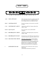
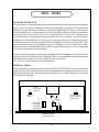
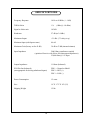
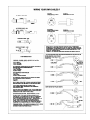
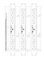
OWNER'S MANUAL
LANGEVIN DUAL MONO
MICROPHONE PREAMPLIFIER
WITH EQ
MANLEY
LABORATORIES, INC.
MANUFACTURED BY:
MANLEY LABORATORIES, INC.
13880 MAGNOLIA AVE.
CHINO, CA. 91710 USA
TEL: (909) 627-4256
FAX: (909) 628-2482
email:[email protected]
http://www.manleylabs.com
REV 4-3-2006
CONTENTS
SECTION
PAGE
INTRODUCTION
3
MAINS CONNECTIONS
4
BASICS
5
CONNECTING YOUR PREAMPLIFIER
6
FRONT PANEL
8
REAR PANEL
9
TECH NOTES
10
SPECIFICATIONS
11
WARRANTY
12
WARRANTY REGISTRATION
13
APPENDIX A: WIRING YOUR OWN CABLES
APPENDIX B: TEMPLATE FOR STORING SETTINGS
INTRODUCTION
THANK YOU!...
for choosing the Langevin Dual Mono Microphone Preamplifier. Manley Labs bought all the rights
to the Langevin name and circuits in 1992. Manley Labs uses the Langevin name for its solid state
products including versions of an all discrete Pultec and Electro-Optical Limiter, as well as, other high
performance non-tube products. This Mic Preamplifier uses an all discrete transistor audio path that
simply sounds pretty damn good. We believe it is because the circuit has good audio performance
before any negative feedback was used to lower the gain and further improve noise and distortion.
This Microphone Preamplifier is a low cost way to enjoy good old high-end performance. It is built
to the same standards as the Manley gear and uses all of the same top quality components. It is one
of the best alternatives for those needing a superb stereo mic pre but for whatever reason cannot get
the Manley Tube Mic Preamp. The Langevin preamplifier also has useful tone shaping (EQ), (fused)
phantom power and very high reliability.
Thank you again, and please enjoy!
WATER & MOISTURE
As with any electrical equipment, this equipment should not be used near water or moisture. If liquid
enters the preamplifier, it must be immediately returned to your dealer for servicing.
SERVICING
The user should not attempt to service this unit beyond that described in the owner's manual. Refer
all servicing to Manley Laboratories.
WARNING!
TO PREVENT THE RISK OF ELECTRIC SHOCK
DO NOT OPEN THE CABINET
REFER SERVICING TO
QUALIFIED PERSONEL
!
3
MAINS
CONNECTIONS
Your unit has been factory set to the correct mains voltage for your country. The voltage setting
is marked on the serial badge, located on the rear panel. Check that this complies with your local
supply. The voltage changeover switch is located inside the unit in the middle of the PCB near the
power transformer. To change the voltage from 120 to 240 volts, simply remove the top cover by
unscrewing the center fixing screw and sliding the top out towards the rear of the chassis. Turn the
top of the voltage changeover switch with a firm positive action using a small flat screwdriver.
Export units for certain markets have a moulded mains plug fitted to comply with local requirements. If your unit does not have a plug fitted the coloured wires should be connected to the
appropriate plug terminals in accordance with the following code.
GREEN/YELLOW
BLUE
BROWN
EARTH
NEUTRAL
LIVE
terminal
terminal
terminal
As the colours of the wires in the mains lead may not correspond with the coloured marking
identifying the terminals in your plug proceed as follows;
The wire which is coloured GREEN/YELLOW must be connected to the terminal in the plug which
is marked by the letter E or by the safety earth symbol or coloured GREEN or GREEN and
YELLOW.
The wire which is coloured BLUE must be connected to the terminal in the plug which is marked
by the letter N or coloured BLACK.
The wire which is coloured BROWN must be connected to the terminal in the plug which is marked
by the letter L or coloured RED.
DO NOT CONNECT/SWITCH ON THE MAINS SUPPLY UNTIL ALL OTHER CONNECTIONS HAVE BEEN MADE.
4
BASICS
This Microphone Preamp, like most mic preamps, is pretty easy to use. First we can discuss why
outboard mic pre's have become "a must have item" in almost every studio even though your console probably
has a bunch of them and that manufacturer claims that they are really great and you don't need outboard mic
pre's. Then, why is everybody buying them, using them, and why are most people going back to tubes or
vintage transistor based circuits?
Good question. The signal from a typical mic is very low - anywhere from 20 to 70 dB below your
normal line level signals. 95% of the time 30 to 40 dB of gain is all that is needed to boost the signal to line
levels. Where you really need a lot of gain is with most ribbon mics and when you are recording chamber
music from a distance. Mic signals are fragile and raw. The fragility is apparent when one compares various
mic pre's - each preamp seems to sound different - no EQ, no compression, nothing elaborate - just basic gain.
Maybe it is the mic reacting different into different circuits. Each preamp, tube or solid state seems to impart
a flavour or color (or personality) of its own. Some of these flavours are subtle and some are not. A few
engineers have an array of mic pre's and use them almost like effects - using each for a certain flavor as needed.
The rest of us only have the budget for one or two great mic pre's so we tend to choose one that sounds "best",
or is priced for us, or is used by "xxxxxx". The Langevin Microphone Preamplifier is superb sounding probably because it has a simple all discrete gain stage with a minimum of components and a minumum
amount of negative feedback. Specifications, while important, will not be truly indicative of an audio
product's "sound" until methods of determining the transient accuracy are established. Transient accuracy
is not a "spec" and test benches don't produce hit records. The transient details are important for reproducing
the true character of the instrument, the room and stereo image. Most solid state circuits use a large amont
of negative feedback to lower noise and distortion at the cost of transient accuracy. This preamplifier started
out clean and quiet so minimal negative feedback was necessary.
Op-amp based designs, by comparison, have dozens of transistors in each "chip" (its easier to
fabricate a transistor than a resistor on silicon), hundreds of dB's of negative feedback and sometimes a few
discrete transistors to provide performance that an "IC" simply cannot. The result is good specs - but that
harsh, hard, cold sound that makes shakers sound like pink noise, makes vocals sibilant in an unpleasant way,
and can only render a 2 dimensional image at best. We prefer tubes or simple discrete circuits.
We mentioned mic signals are fragile and raw. Some consider that the "headroom" factor is the most
important issue in mic pre's. We believe that it is just one of a number of issues including the harmonic
character of the distortion. Except for the final output, all circuits are "Class A" which is usually associated
with no crossover distortion and near clipping will be even order distortion and less upper harmonics.This
Preamplifier has more headroom than most solid state mic pre's because of the 48 volt power supply used,
compared to 30 volts (+/- 15V or 24 volts) used in other designs. If overdriven, which is not easy, it starts
to clip in a gentle, smooth way.
Which brings us to the next topic - METERING - We do get questions like "How do I set up the Mic
Pre levels when there are no meters?". Answer - Look at where you are sending the signal, if it has meters
- use them. Why ? Most people are recording to digital mediums where there is no real standard. If you use
the tape machine's digital meters, you will most likely get the best recording levels using the machine's meters.
If we included a meter, it would most likely not be "calibrated" to your meters and mislead or confuse the
user. Also, if we included metering, it would be VU which is a standard of its own appropriate for analog
tape only. Turn up the LEVEL control until the loudest peaks to tape are a few dB below maximum and not
producing "Over" Leds (for safety) and not too low (10 dB below clipping or lower). If we had a "Clipping
LED" for the preamp, it would be probably be dark when the machine's meters were pinned. Cosmetically
a meter might be nice but functionally it would be misleading or mostly useless.
5
CONNECTING YOUR PREAMPLIFIER
Easy - Connect the mic to the Microphone Input XLR, then connect the Line Output to your
tape machine or console. Read on, there are some things to consider.
On the back panel are female XLR's labelled MIC INPUT A and MIC INPUT B. The signal
from the MICROPHONES get plugged in here. Here are a few warnings and suggestions.
These XLR connectors also "send" PHANTOM POWER to the mics. Some mics can be
damaged by the 48 volts of phantom power. A few PZMs and a few ribbon mics have been
known to "fry" when fed phantom power. The suggestion is to ALWAYS have PHANTOM
switched off when switching mics, cables, patches that involve mics etc. You ONLY use
phantom power for PRO SOLID STATE "FET' CONDENSOR MICS. Tube mics, dynamic
mics, ribbon mics and battery powered mics should have phantom switched "off". This is true
for all mic pre's. With this MIC PRE you "PULL THE TOGGLE to SWITCH PHANTOM".
It is a locking toggle to prevent "accidents". The second great reason for not using phantom if
you don't have to is that - if you change a connection with phantom on, then the pre amp will
be fed a quick burst of 48 volts (when it normally is amplifying about a hundredth of a volt),
which can then be monitored - usually once. After you have replaced your speakers, you have
learned a valuable lesson about turning down the volume of the monitors before changing
mics or mic patches. This is a good idea with phantom on or off. Consider a variation of this any mic connection just a little bit bad,will be extra noisy with phantom turned on. This goes
for cables, patchbays, patch cords etc. Suggestion #2 - Avoid running mic signals through
patchbays. Some patchbays "ground" all the "sleeves" which can add a ground loop into your
delicate mic signal. Suggestion #3 - Set up the Mic Pre in the studio near the mic and use a
short mic cable. Why ? Microphones often have "light duty" line drivers and you can lose an
audible amount of signal in long cables. You can get the best fidelity by having the Mic Pre
close to the mic at the "cost" of having to walk into the studio to adjust a level control. You
also avoid almost all of that phantom power / patching problem because now you are patching
a regular line level signal only.
The INPUT & OUTPUTS XLR PINOUTS are:
PIN 1 = CIRCUIT GROUND
PIN 2 = HOT or positive going phase
PIN 3 = LOW or negative going phase
The OUTPUTs are simple and balanced. They will feed balanced inputs but not unbalanced
inputs "correctly". When one is plugged into an unbalanced input, expect a 6 dB loss of
output level. This will occur no matter how you wire the cable. The best way to drive an
unbalanced input with this unit is not to connect to PIN 3 at the output XLR - just use PIN 1
(ground) and PIN 2 (signal). Better to have PIN 3's signal float than short. You may not
notice the 6 dB "loss" because the preamp still has good headroom.
NOTE: The DIRECT INPUT comes in AFTER the INPUT ATTENUATOR. It comes in at
the wiper (output) of the INPUT ATTENUATOR pot into the first transistor. Thus when you
turn down that INPUT ATTENTUATOR you are moving that point closer towards ground
and loading down that DIRECT INPUT. This will indeed affect frequency response. Solution:
keep the INPUT ATTENUATOR UP (fully clockwise) when you are using the DIRECT
INPUT.
6
Reversing the polarity or phase is often needed when two or more mics are picking up the
same source. For example it would be needed when one mics the top and bottom of a snare - one
skin is going towards one mic and the other skin is going away from the other mic. If one signal
is not "reversed" then you lose lows. Polarity reverse can also help with some vocal / mic /
headphone situations because " somewhere " the polarity flipped one too many times. It happens.
General advise - try it each way - listen, with vocals, always ask the singer which way they prefer.
The headphones may "cancel" with the sound they hear in their skull while singing. This Mic Pre
has no provision for changing the polarity. If you are recording direct to tape it is a good idea to
have a few phase reverse adapters on hand. All you need is two XLRs (a male and female) and a
foot of mic cable. It doesn't matter which end is which. Wire it up as follows:
PIN 1 (Shield) > PIN 1
PIN 2 > PIN 3
PIN 3 > PIN 2
You can use this between the MIC and PREAMP or often between the PREAMP and TAPE. If
you use both at once, you come out in phase. Mark these cables PHASE REV ! This is another
reason why a 1 foot cable is good - thus avoiding confusion with normal cables.
We did include a 1/4 inch phone jack input for electronic instruments. This is not quite
the same thing as a direct box because the input impedance is about 23K ohms compared to 1M
ohms of a typical DI - which means it sucks for guitar and bass. It is intended for the dozens of
synths and drum machines in many rooms. It provides a good input with gain control and EQ. You
can use either the INSTRUMENT INPUT or MIC INPUT but not both at the same time.
On the wiring PIN-OUTS, you may have noticed we specified CIRCUIT GROUND rather
than just GROUND. We have a few terminals on the back panel for various "ground schemes".
The CIRCUIT GROUND is the same ground as the electronics in the Mic Pre while the CHASSIS
GROUND is the same as the steel enclosure that is bolted to the rack and is also connected to the
"third pin AC Mains Ground. Both terminals are normally connected together with a small "ground
strap" but this strap can be moved to the side and wire can be attached to the terminals. These
are "MINI BANANA" style and will not accept regular size bananas found on electronic test gear.
Be careful with the ground strap because it can get lost if the terminals are loose. If it does get lost
- you can use a short bare wire.
There are two good reasons for using these ground terminals. The first is finding and fixing
hum and the second is preventing hum. If you have plugged everything in right and you are getting
hum then you have a number of options with these terminals. You can try simply moving the strap
so that chassis ground is separate from circuit ground. This is similar to breaking off the third pin
AC ground but includes the ground from rack mounting . One can experiment with attaching a
wire between the console ground and the circuit ground or between a rack and the chassis ground.
These are all techniques some technicians use when wiring studios. They also often cut the ground
(shield) on one side of the cable to prevent loops. DO NOT cut the shield on MIC cables because
you lose phantom, shielding at the mic, and hum only gets worse !
One other cause of hum - Some gear may radiate a field into whatever is closest. Move
the Mic Pre or the offender away from each other. That may help.
7
FRONT
PHANTOM 48V
INPUT
80 Hz
ATTENUATE
40 Hz
A
B
L.F.
-10
EQ IN
+10
EQ OUT
C
D
H.F.
-10
PANEL
POWER
PHANTOM 48V
80 Hz
12 KHz
+10
E
8 KHz
DISCRETE DUAL MONO MICROPHONE PREAMPLIFIER
F
G
I
J
40 Hz
K
L.F.
-10
EQ IN
+10
EQ OUT
L M
H.F.
-10
12 KHz
+10
N
8 KHz
O
INPUT
ATTENUATE
P
A&P
INPUT ATTENUATE
This is the input level for the microphone signal. The
best setting is achieved by watching the meters of
the recording machine as you adjust this control.
B&K
LOW FREQ. SELECT
Selects low frequency to be boosted or cut (80 Hz
or 40 Hz).
C&L
LOW FREQUENCY ADJUST
Continuously variable low frequency adjust from 10dB to +10dB.
D&M
EQ IN / EQ OUT
Selects EQ in the circuit or BYPASSED
completely.
E&N
HIGH FREQUENCY ADJUST
Continuously variable high frequency adjust from 10 dB to +10dB.
F&O
HIGH FREQUENCY SELECT
Selects between 8 and 12 KHz peak adjust. Boost or
Cut for this selection is adjusted by controls E or H.
G&H
PHANTOM SUPPLY SWITCH
PULL this switch to unlock to change phantom
power (48 volts) for each channel. The phantom
switch locks to prevent accidental switching when
phantom power is not desired. NEVER apply
phantom volts to an unbalanced source (some
battery powered and tube mics are unbalanced).
I
POWER SWITCH & LED
Switch up to power ON the unit, down to power
OFF the unit.
LED Illuminates when unit is powered on.
8
REAR PANEL
A
B
C
D
E
F
G
H
I
A
INSTRUMENT INPUT
Optimised for Synths and drum machines but not for
guitars or basses. Use a regular "DI" into the MIC INPUT
for guitars and basses. Use only the instrument input or
MIC INPUT but not both at the same time.
B
INPUT XLR (Right Channel)
Balanced XLR input. PINOUT: Pin 1 Ground
Pin 2 POSITIVE going phase (+)
Pin 3 NEGATIVE going phase (-)
C
OUTPUT XLR (Right Channel)
Balanced XLR output. PINOUT: Pin 1 Ground
Pin 2 POSITIVE going phase (+)
Pin 3 NEGATIVE going phase (-)
We do not recommend that this output be used with
unbalanced inputs. If you have to - do not connect PIN 3.
D
FUSE HOLDER
To remove the fuse, push and turn the fuse holder cap. A
1/2 Amp SLO-BLO fuse is recommended. In fact, ONLY
replace with the same type and value for safety.
E
IEC MAINS SOCKET
Accepts standard 50/60 Hz AC mains voltage. The
correct voltage should be factory set for your country. If it
needs to checked or changed, there is a switch inside the
unit for 110 or 220 VAC operation. See page 10.
F
GROUND TERMINALS
Use these terminals to solve hum problems. See page 7.
Normally these terminals are joined by a "ground strap".
G
OUTPUT XLR (Left Channel)
Balanced XLR output. PINOUT: Pin 1 Ground
Pin 2 POSITIVE going phase (+)
Pin 3 NEGATIVE going phase (-)
We do not recommend that this output be used with
unbalanced inputs. If you have to - do not connect PIN 3.
H
INPUT XLR (Right Channel)
Balanced XLR input. PINOUT: Pin 1 Ground
Pin 2 POSITIVE going phase (+)
Pin 3 NEGATIVE going phase (-)
I
INSTRUMENT INPUT
Optimised for synths and drum machines but not for
guitars or basses. For guitars use a regular "DI" into the
MIC INPUT. Use only the instrument input or MIC
INPUT but not both at the same time.
9
TECH
NOTES
PHANTOM POWER FUSE
In earlier sections we explained most of the possible small disasters that can happen when phantom
power is used. The big one is damage to other gear not designed for phantom. This includes old
ribbon mics, non-pro battery powered mics and possibly other things we have yet to hear about.
FOUR reasonable rules: 1) Most modern mics with 3 pin XLR connectors will be safe and there is
no need to worry unless you own some exotic or real cheap mics. 2) ONLY FET condensor mics
need phantom power and some direct boxes can either use it or use batteries. 3) Because usually
phantom power is not needed, leave it off to prevent excessive noise from poor connections & cables
and because some mics that don't need phantom sound slightly better with it off. 4) ALWAYS turn
the monitors down when you turn phantom power on or change a mic or mic cable or mic patch.
How can I tell when I need phantom? There will be no signal at all from the mic. However this might
be caused by any number of reasons (cables).
If you have lost phantom power in this mic pre (the phantom LED won't light) it is very likely because
somebody broke one of the above rules. It happens. There is a fuse inside the unit for these situations
and it has blown. Unplug the AC then, replace the fuse with another
AGC 4/10 A (fast blow) and you are back in business.
INTERNAL TRIMS
The drawing below shows the location of the LINE VOLTAGE SELECT for you international
engineers (110 or 220). It also shows the locations of the phantom fuse, channel gain trims and power
supply trims and test points. These are all factory set and it is very unlikely that they will ever need
to be adjusted or changed.
LINE
VOLTAGE
SELECT
TRIM1
TRIM01
C202
CHAN A
GAIN
PHANTOM
FUSE AGC
4/10 AMP
FAST BLOW
CHAN B GAIN
(FACTORY SET
FOR 45 DB)
TRIM201
POWER SUPPLY
48 VDC ADJUST
10
GROUND
+48 VDC
SPECIFICATIONS
Frequency Response
10 Hz to 20 KHz (+/- 1 dB)
THD & Noise
.1%
Signal to Noise ratio
103 dB
Headroom
27 dB (ref +4 dBv)
Maximum Output
+31 dBv (75 volts p to p)
Maximum Input (with Input at max)
84 mV
Maximum Gain (factory set for 45 dB)
38 dB to 53 dB (internal trimmer)
Input Impedance
(1Khz @ +10 dBm)
2400 Ohm, transformer coupled
(optimised for mics with 100 to 600 ohm output impedances)
23,000 Ohm @ 1/4" input
Output Impedance
11 Ohms (balanced)
XLR Pin-Out (balanced)
(not appropriate for driving unbalanced inputs)
PIN 1 = Ground or Shield
PIN 2 = HOT (+)
PIN 3 = LOW (-)
Power Consumption
12 watts
Size
19" X 1.75" X 10" (1U)
Shipping Weight
12 lbs
11
WARRANTY
All Manley Laboratories equipment is covered by a limited warranty against defects in materials and
workmanship for a period of 90 days from date of purchase to the original purchaser only. A further
optional limited 5 year transferrable warranty is available upon proper registration of ownership within
30 days of date of first purchase.
Proper registration is made by filling out and returning to the factory the warranty card attached to this
general warranty statement, along with a copy of the original sales receipt as proof of the original date
of purchase, or registration can be made online in the Tech Support section of www.manleylabs.com.
This warranty is provided by the dealer where the unit was purchased, and by Manley Laboratories,
Inc. Under the terms of the warranty defective parts will be repaired or replaced without charge,
excepting the cost of tubes. Vacuum tubes and meter or badge lamps are warranted for six months
provided the warranty registration is completed as outlined above.
If a Manley Laboratories product fails to meet the above warranty, then the purchaser's sole remedy
shall be to first obtain a Repair Authorisation from Manley Laboratories and return the product to
Manley Laboratories, where the defect will be repaired without charge for parts and labour. All returns
to the factory must be in the original packing, accompanied by the Repair Authorisation, and must be
shipped to Manley Laboratories via insured freight at the customer's own expense. Factory original
packaging can be ordered from Manley Labs. Customer will be charged for new factory original
packaging if customer fails to ship product to Manley Labs in the original factory packaging. After
repair, the product will then be returned to customer via prepaid, insured freight, method and carrier to
be determined solely by Manley Laboratories. Manley Laboratories will not pay for express or
overnight freight service nor will Manley Laboratories pay for shipments to locations outside the USA.
Charges for unauthorized service and transportation costs are not reimbursable under this warranty,
and all warrantees, express or implied, become null and void where the product has been damaged by
misuse, accident, neglect, modification, tampering or unauthorized alteration by anyone other than
Manley Laboratories.
The warrantor assumes no liability for property damage or any other incidental or consequental
damage whatsoever which may result from failure of this product. Any and all warrantees of
merchantability and fitness implied by law are limited to the duration of the expressed warranty. All
warrantees apply only to Manley Laboratories products purchased and used in the USA. All
warrantees apply only to Manley Laboratories products originally purchased from an authorised
Manley dealer. Warranties for Manley Laboratories products purchased outside the USA will be
covered by the Manley Importer for that specific country or region. "Grey Market" purchases are not
covered by any warranty. In the case that a Manley Laboratories product must be returned to the
factory from outside the USA, customer shall adhere to specific shipping, customs, and commercial
invoicing instructions given with the Return Authorisation as Manley Laboratories will not be
responsible for transportation costs or customs fees related to any importation or re-exportation
charges whatsoever.
Some states do not allow limitations on how long an implied warranty lasts, so the above limitations
may not apply to you. Some states do not allow the exclusion or limitation of incidental or
consequential damages, so the above exclusion may not apply to you. This warranty gives you specific
legal rights and you may also have other rights which vary from state to state.
For Tech Support and Repair Authorisation, please contact:
MANLEY LABORATORIES, INC.
13880 MAGNOLIA AVE.
CHINO, CA. 91710 USA
TEL: (909) 627-4256
FAX: (909) 628-2482
email: [email protected]
WARRANTY REGISTRATION
We ask, grovel and beg that you please fill out this registration form and send the bottom half to:
MANLEY LABORATORIES
REGISTRATION DEPARTMENT
13880 MAGNOLIA AVE.
CHINO CA, 91710 USA
Or you may FAX this form in to: +1 (909) 628-2482 or you may fill in the online warranty
registration form found in the Tech Support section of our website www.manleylabs.com or you can
be really diligent and register your warranty three times to see if we get confused!
Registration entitles you to product support, full warranty benefits, and notice of product
enhancements and upgrades, even though it doesn't necessarily mean that you will get them (Just
kidding!) You MUST complete and return the following to validate your warranty and registration.
Thank you again for choosing Manley gear and reading all the way through The Owner's Manual.
(We really mean that sincerely, the bit about thanking you for choosing our gear. THANK YOU!!!)
MODEL _______________ SERIAL #__________________
PURCHASE DATE ______________ SUPPLIER ______________________
-------------------------------------------------------------------------------------------------------PLEASE DETACH THIS PORTION AND SEND IT TO MANLEY LABORATORIES
MODEL _______________ SERIAL #__________________
PURCHASE DATE ______________ SUPPLIER ______________________
NAME OF OWNER _______________________________________________
ADDRESS ______________________________________________________
CITY, STATE, ZIP ________________________________________________
EMAIL: ________________________________________________________
TELEPHONE NUMBER___________________________________________
COMMENTS OR SUGGESTIONS?__________________________________
________________________________________________________________