1
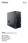
Solo Quiet Mini Tower Case User’s Manual Manuel de l’utilisateur Anwenderhandbuch Manuale per l’operatore Manual del usuario পᡅ䂀ᯢ 1 At Antec, we continually refine and improve our products to ensure the highest quality. So it’s possible that your new case may differ slightly from the descriptions in this manual. This isn’t a problem; it’s simply an improvement. As of the date of publication, all features, descriptions, and illustrations in this manual are correct. Disclaimer This manual is intended only as a guide for Antec’s Computer Enclosures. For more comprehensive instructions on installing the motherboard and peripherals, please refer to the user’s manuals which come with the components and drives. Solo User’s Manual Solo–Quiet Mini Tower Case This case is designed with Quiet Computing™ in mind. Apart from the solid steel construction (1.0 mm think steel), it comes equipped with several unique features that make this case quiet and cool. 1. 2. 3. 4. 5. 6. Two layer steel with polycarbonate side and top panels to deaden noise Dual hard drive mounting system for maximum noise reduction Quiet 120 mm TriCool™ rear fan Dual front 92 mm fan mounts for spot cooling hard disks Intake vents at sides to reduce the noise Built-in Cable Organizer to keep cables neat This case does not come with a power supply. Be sure to choose a power supply appropriate to your motherboard’s requirements. When building a quiet or silent system please realize that the components you choose will greatly impact the end result. Solo by itself will not make a loud system quiet. Its design can reduce the noise emitted by any system, but for a truly Quiet Computing™ experience you should exercise care in choosing the components used in your system. Setting Up 1. Place the case upright on a flat, stable surface. 2. Loosen the thumbscrews from the right side panel. Remove it by swinging it out. Note: Don’t use your fingernail to pry or lift the panels. 3. Inside the case you should see some wiring with marked connectors (USB, PWR etc.), an installed I/O panel, a power cord, a plastic bag containing more hardware (screws, brass standoffs, plastic stands, etc.), and six drive rails. 4. There are three plastic tabs on the left side of the bezel. They fasten the front bezel to the metal chassis. Release the tabs from the top down to release the bezel. 5. Swing open the bezel and gently lift it upward. The front bezel will come off easily. Set the bezel aside in a safe place. 1 Installing the Motherboard This manual does not cover CPU, RAM, or expansion card installation. Please consult your motherboard manual for specific mounting instructions and troubleshooting. 1. Lay the case down, with the open side facing up. The drive cages should be visible. 2. Make sure you have the correct I/O panel for the motherboard. If the panel provided with the case isn’t suitable, please contact the motherboard manufacturer for the correct I/O panel. 3. Line up the motherboard with the standoff holes, and remember which holes are lined up. Not all motherboards will match with all the provided holes; this is normal, and won’t affect functionality. 4. Remove your motherboard by lifting it up. 5. Screw the brass standoffs into the threaded holes that line up with your motherboard. Do not overtighten the standoffs. Some standoffs may be pre-installed for your convenience. 6. Place the motherboard on the brass standoffs. 7. Screw in the motherboard to the standoffs with the provided Philips-head screws. The motherboard is now installed. Installing the Power Supply 1. With the case upright, place the power supply on the support beam that runs from the 5.25” drive bays to the back of the case. 2. Push the power supply to the back of the case and align the mounting holes. 3. Attach the power supply to the case with the screws provided. Connecting the Power and LED 1. Connect the Reset switch (labeled RESET SW) to the motherboard at the RST connector. Make sure the label always faces the front of the case. 2. Power LED (labeled POWER LED) connector is located behind the Reset connector. 3. Power Switch (labeled POWER SW) connects to the PWR connector on the motherboard. 4. Hard Drive LED (labeled H.D.D. LED) connects to the IDE connector. Connecting the USB Ports You will find a single 10-pin connector on a cable attached to the front USB ports. This is an Intel standard connector, which is keyed so that it can’t be accidentally, reversed when connected to a proper Intel standard motherboard. Connect the 10-pin connector to the motherboard headers so that the blocked pin fits over the missing header pin. Note: Please check the motherboard manual for the USB header pin layout and make sure it matches the attached table. If it does not match this Intel standard, please call Antec customer service at (800) 22ANTEC (North America) or +31 (0) 10 462-2060 Europe) to buy a USB adapter. This adapter will allow you to connect the front USB to the motherboard on a pin-by-pin basis. 2 Motherboard Pin Layout 1 2 9 10 Pin Signal Names Pin Signal Names 1 USB Power 1 2 USB Power 2 3 Negative Signal 1 4 Negative Signal 2 5 Positive Signal 1 6 Positive Signal 2 7 Ground 1 8 Ground 2 9 Key (No Connection) 10 Empty Pin Connecting the IEEE 1394 (FireWire®, i.Link®) Port You will find a single 10-pin connector on a cable attached to the front IEEE 1394 connection. This is an Intel standard connector, which is keyed so that it can’t be accidentally reversed when connected to a proper Intel standard motherboard header. Connect the 10-pin connector to the motherboard header so that the blocked pin fits over the missing header pin. Note: Please check the motherboard manual for the IEEE 1394 header pin layout and make sure it matches the attached table. If you intend to connect the front FireWire port to an IEEE 1394 add-on card that comes with an external-type IEEE1394 connector, please call Antec customer service at (800) 22ANTEC (North America) or +31 (0) 10 462-2060 (Europe) to buy an adapter. This adapter will allow you to connect the front IEEE 1394 port to the external-type connector. Pin Assignment for Front Panel IEEE 1394 Connector 1 2 9 10 Pin Signal Names Pin 2 Signal Names 1 TPA+ 3 Ground 4 Ground 5 TPB+ 6 TPB– 7 +12V (Fused) 9 Key (No Pin) 3 8 10 TPA– +12V (Fused) Ground Connecting the Audio Ports There is an Intel standard 10-pin connector (with 7 individual wires with connectors) coming out from the front panel speaker and microphone connection. If the motherboard supports Intel’s standard onboard audio connector, you can plug in the 10-pin connector directly onto the board. For non-Intel standard audio connection, you need to plug the 7 individual connectors to the motherboard. Please see the instruction: Locate the internal audio connectors from the motherboard or sound card. Consult the motherboard or sound card manual for the pin-out positions. 1. 2. 3. 4. 5. 6. 7. Microphone Signal Pin: Connect the MIC connector to this pin. Microphone Power: Connect the MIC-BIAS connector to this pin. Ground Pin: Connect the AUD GND connector to this pin. Front Right Speaker Out Pin: Connect the FPOUT-R connector to this pin. Front Left Speaker Out Pin: Connect the FPOUT-L connector to this pin. Rear Right Speaker Out Pin: Connect the RET-R connector to this pin. Rear Left Speaker Out Pin: Connect RET-L connector to this pin. Hard Disk Installation This case comes with dual hard disk mounting systems. We recommend using one or the other, but not both at the same time. The Tray Mount There is a hard disk cage under the external 5.25” drive. You can mount four hard drives using the trays inside it. 1. Open the front bezel as described in Setting Up section. 2. Loosen the two thumbscrews. Swing open the fan cage and gently lift the cage upward to remove it. You will see four drive trays with soft silicon grommets inside the cage. 3. Squeeze the metal clips on each side of the tray and slide the tray out. 4. Mount your hard drive into the drive tray through the bottom silicon grommets with the special screws provided. Note: Don’t over-tighten. Over-tightening the screws will reduce the vibration and noise-dampening ability of the rubber grommets. 5. Slide and lock the tray back into the case. 6. Find a 4-pin Molex connector on the power supply and connect it to the male 4-pin connector on the device. 7. Repeat the same procedure for the other devices as necessary. 8. Put the front fan cage back to the case. If you plan to mount the optional 92 mm case fans, do it now. See the Cooling section for fan installation. 4 The Suspension Mount This is the ultimate hard disk mounting solution to reduce the hard drive noise. There are three sets of Suspenders inside the cage to mount three hard drives. Each hard drive needs two Suspenders (front and rear) to mount it. Note: please DO NOT transport your system with your hard disks in mounted suspension. The drives may slip from the Suspenders and damage the hard drives and other components inside the case. 1. Remove the trays from the cages. Store them in a safe place. You won’t need them now. 2. Insert the hard drive through the front Suspender from the front. See picture 1. 3. Adjust the hard drive position so it has at least 10mm clearance from the front 92 mm fan (fan not included). See picture 2. 4. Find a 4-pin Molex connector on the power supply and connect it to the male 4-pin connector on the device. 5. Repeat the same procedure for the other drives as necessary. 6. Put the front fan cage back to the case. If you plan to mount the optional 92 mm case fans, do it now. See the Cooling section for fan installation Picture 1 Picture 2 5.25” Device Installation There are four external 5.25” drive bays (one with 5.25” to 3.5” Adapter). Carefully remove the metal plate covering the drive bay you wish to use. 1. Take two plastic drive rails and mount them to the sides of the 5.25” device. Make sure to align the front set of the screw holes for the devices. Also make sure the end of the drive rail is angled away from the device and facing forward. 2. Slide the device into the drive bay until you hear a click. 3. Mount the other devices accordingly. 4. Connect a large 4-pin connector from the power supply to the male 4-pin connector on each of the devices. To 1. 2. 3. install a floppy or other external 3.5” device to the 5.25” to 3.5” Adapter: Slide the Adapter out. Place the drive to the Adapter and fasten the drive with screws provided. Find a 4-pin floppy power connector on the power supply and connect it to the male 4-pin connector on the devices. 5 Cable Organizer There are six hook type structures (Cable Organizers) located behind the hard drive cage. You can use the Cable Organizers to tuck away cables in order to increase the airflow within the case. To get to the Cable Organizer you need to open the right side panel. Cooling System The TriCool™ fan: The case includes one 120mm TriCool™ fan installed in the rear. This fan has a three-speed switch that lets you choose between quiet, performance, or maximum cooling. (See specifications below.) The fan is installed so that the air is blowing out of the case. Connect a large 4-pin connector from the power supply to the male 4-pin connector on the fan. Note: The minimum voltage to start the fan is 5V. We recommend setting the fan speed to High if you choose to connect the fan to a fan control device or to the Fan-Only connector found on some of Antec’s power supplies. A fan-controlled-device regulates the fan speed by varying the voltage to it. The voltage may start as low as 4.5V to 5V. Connecting a TriCool™ fan set on Medium or Low to a fan-control device may result in the fan not being able to start. The already lowered voltage from the fan control device will be further reduced by the TriCool™ circuitry below 5V. Specifications: Size: Rated Voltage: Operating Voltage: Speed Input Current 120 mm x 120 mm x 25.4 mm DC 12V 10.2V ~ 13.8V Air Flow Static Pressure Acoustical Noise Input Power High 2000 RPM 0.24A (Max.) 2.24 m³ / min (79 CFM) 2.54 mm-H2O (0.10 inch-H2O) 30 dBA 2.9 W Medium 1600 RPM 0.2A 1.59 m³ / min (56 CFM) 1.53 mm-H2O (0.06 inch-H2O) 28 dBA 2.4 W Low 1200 RPM 0.13A 1.1 m³ / min (39 CFM) 0.92 mm-H2O (0.04 inch-H2O) 25 dBA 1.6 W The Front 92 mm fans You can install two 92 mm fans to the fan cage in front of the internal 3.5” drives. These fans must be installed so that the air is blowing into the case. We recommend using Antec 92 mm TriCool™ fans to balance quiet performance with maximum cooling. See our web site for product information. Note: Please choose your fan speed wisely. In most cases, a medium or even low speed setting will be enough to supply adequate cooling. 6 Antec, Inc. 47900 Fremont Blvd. Fremont, CA 94538 USA tel: 510-770-1200 fax: 510-770-1288 Antec Europe B.V. Sydneystraat 33 3047 BP Rotterdam The Netherlands tel: +31 (0) 10 462-2060 fax: +31 (0) 10 437-1752 Customer Support: US & Canada 1-800-22ANTEC [email protected] Europe +31 (0) 10 462-2060 [email protected] www.antec.com © Copyright 2006 Antec, Inc. All rights reserved. All trademarks are the property of their respective owners. Reproduction in whole or in part without written permission is prohibited. Printed in China. Version 1.0.1 01/23/2006 43