1
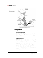
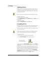
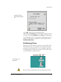
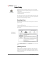
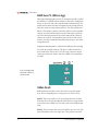
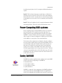
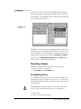
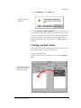
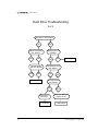
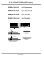
Storage Devices
Training Module
October 1997
This module was written and compiled by: Mark Wood.
This Power Computing module was written, illustrated, edited, and
produced on a PowerWaveª 150 running Apple¨ MacOS 8¨. The
software applications used include: Adobe¨ FrameMaker¨, Photoshop¨ and Illustrator¨.
This Power Computing module was written, edited and produced
on a desktop publishing system using a Power Computing system
that uses the Mac OS.
PowerCurve, PowerCenter, PowerWave, PowerBase, PowerTower,
PowerCenter Pro, and PowerTower Pro are trademarks of Power
Computing Corporation.
Every effort has been made to ensure that the information in the
module is accurate. Power Computing is not responsible for printing or clerical errors.
© 1997 Power Computing Corporation
Power Computing Corporation
2400 S. IH-35
Round Rock, Texas 78681-7903
STORAGE DEVICES
Table of Contents
Chapter 1 - Hardware Setup ...................................................... 5
Introduction ............................................................................... 5
Types of Storage Devices ........................................................... 5
Busses ...................................................................................... 6
Enhanced Intelligent Device Electronics (EIDE)...... 6
Small Computer System Interface (SCSI) ................. 6
ConÞguration ........................................................................... 10
Floppy disk drive....................................................... 10
Hard disk drive.......................................................... 10
Iomega Jaz and Zip drives ........................................ 11
CD-ROM drive ........................................................... 11
Adaptec PCI cards ..................................................... 11
Jumper positions....................................................... 12
Audio/Video Performance ....................................................... 12
Chapter 2 - Software Tools ...................................................... 15
Hard Disk ToolKit..................................................................... 16
Mounting and unmounting devices......................... 17
Updating drivers........................................................ 18
Formatting drives...................................................... 18
Partitioning Drives .................................................... 19
Testing drives............................................................. 21
Drive Setup............................................................................... 22
Mounting drives ........................................................ 22
Updating drivers........................................................ 22
Formatting drives...................................................... 23
Iomega Tools ............................................................................ 25
Formatting disks........................................................ 25
Changing drive options ............................................ 27
Disk First Aid ............................................................................ 28
Other Disk Repair .................................................................... 28
CD-ROM ToolKit....................................................................... 29
Setup options ............................................................ 29
Installing software from cd....................................... 30
PowerDomain Control/Board Control ................................... 31
Power Domain Control............................................. 31
Board Control............................................................ 32
Chapter 3 - RAID........................................................................ 33
DeÞnition.................................................................................. 33
RAID Levels............................................................................... 33
Storage Devices Training Module
3
Ñ EDUCATION
RAID Level 0 (Striping)............................................. 33
RAID Level 1 (Mirroring) .......................................... 34
Other levels ............................................................... 34
Power Computing RAID systems ............................................ 35
Conley SoftRAID....................................................................... 35
Mounting volumes .................................................... 36
Formatting drives...................................................... 36
Creating a striped volume ........................................ 37
Creating a mirrored volume..................................... 39
Updating disk drivers................................................ 40
Chapter 4 - Troubleshooting ................................................... 43
Floppy Disk Drive .................................................................... 43
Hard Disk Drive........................................................................ 44
Gray Screen at startup .............................................. 45
Flashing question mark at startup ........................... 45
Freezes at Happy Mac ............................................... 45
Corrupted Files ......................................................... 45
Slow performance..................................................... 46
Abnormal noise ......................................................... 46
Removeable Disk Drive ........................................................... 50
CD-ROM Drive ......................................................................... 51
RAID .................................................................................... 52
Failed stripe ............................................................... 52
Mirror out-of-sync ..................................................... 52
Failed mirror.............................................................. 53
4
Power Computing Ñ ConÞdential
STORAGE DEVICES
Hardware Setup
Introduction
When something goes wrong with a computer, storage devices are frequently involved. Disk drives are the components of a computer that
contain moving parts, and are therefore the most prone to failure.
Additionally, the writeable nature of most storage devices makes the
information they contain susceptable to corruption. Because of this, all
service technicians should have a thorough knowledge of the storage
devices used in the computer and how to isolate problems involving
them.
This training module covers the types of storage devices used in Power
Computing equipment, how they are conÞgured, and how to troubleshoot problems with them.
Types of Storage Devices
Power Computing offers a wide range of storage devices for its computers. Some of them are standard equipment on all models, and others
are available as options.
Floppy Disk. A ßoppy disk drive is standard equipment on all Power
Computing computers. The 3 1/2-inch disks hold 1.44 Mb of data. The
drive is the same self-ejecting mechanism used on Apple Macintosh
computers.
Fixed Disk. Hard disk drives are standard on all Power Computing
models, in capacaties from 500 Mb to 4 Gb.
Removeable Disk. Removeable disks drives are mechanisms
designed so the storage medium may be taken out of the drive for safekeeping and transportation. Iomega¨ Zipª (100 Mb) and Jazª (1
Gb) drives are optional equpment on some Power Computing models.
CD-ROM. CD-ROM drives were optional on Power ComputingÕs early
models, and are now standard equipment. Drive speeds range from 4x
to 16x.
Storage Devices Training Module
5
Ñ EDUCATION
RAID. Some applications, such as digital video, require high-performance storge devices. To meet this need, a Redundant Array of Inexpensive Disks (RAID) is available as an option for the PowerTower
Proª.
Busses
All storage devices communicate with the rest of the computer
through a specialized data pathway called a bus. With the exception of
the ßoppy drive, Power Computing uses one of two types of busses for
its storage devices.
Enhanced Intelligent Device Electronics
(EIDE)
EIDE is a moderate-performance, low-cost bus that is widely used in
IBM-compatible computers. EIDE is a 16-bit bus that can address hard
drives as large as 8.4 Gb, and is also known by the name Advanced
Technology Interface (ATA). Apple¨ has recently begun using EIDE
devices in its Performaª and PowerBookª products. Power Computing uses EIDE hard drives as standard equipment in its PowerBase
model. EIDE devices share bus control duties with circuits on a card, or
on the main logic board in the case of the PowerBaseª, and can be set
to either a master or slave conÞguration. The master device controls
the signals passing to the slave devices. The hard drive in the PowerBase is set to master. The PowerBase is designed to use a single EIDE
device; the CD-ROM drive and any removable drives in the PowerBase
are connected to a separate SCSI bus.
Small Computer System Interface (SCSI)
g
SCSI is a widely used method of connecting storage devices within a
computer and peripheral devices outside of a computer. It provides a
relatively high speed connection, and allows multiple devices to be
connected together in a chain. Most Macintosh¨ computers and all
Power Computing models use SCSI devices. SCSI is used on IBM-compatible computers when high-performance storage devices are
required.
SCSI is a standard speciÞcation that has been developed and expanded
to meet a range of needs. Power Computing uses several different
forms of SCSI busses.
6
Power Computing Ñ ConÞdential
STORAGE DEVICES
Standard SCSI. This is the most common form of SCSI bus, widely
used for moderate speed devices like some internal hard drives, CDROM drives and removable disk drives. It is also used to connect external devices such as hard drives and scanners. Standard SCSI transfers 8
bits at a ÒnormalÓ rate and supports a data transfer rate of 5 Mb/sec on
a 50-pin internal or 25-pin external cable.
Fast SCSI. This is a higher speed SCSI bus used to connect high-performance hard drives. Some computers, like the PowerWaveª and
PowerTower Pro, have a Fast SCSI bus for connecting internal storage
devices. Fast SCSI transfers 8 bits at an accelerated rate and supports
data transfer rates of 10 Mb/sec on a 50-pin internal cable.
Wide SCSI. This is also a high speed SCSI bus for high performance
hard drives. Wide SCSI transfers 16 bits at a normal rate and supports
data transfer rates of 10 Mb/sec on a 68-pin cable.
Ultra SCSI. Ultra SCSI is a protocol for sending data at a greatly accelerated rate. This protocol is used with both narrow (8-bit) and wide
(16-bit) devices to achieve data transfer rates of 20 Mb/sec. and 40 Mb/
sec., respectively.
Power Computing implements SCSI on its computers in several different fashions. SCSI busses are controlled by special-purpose circuits
that coordinate communication between devices and with the computer. Some computers, such as the PowerCenterª, have SCSI controllers on the main logic board that operate one SCSI bus for both
internal and external devices. These models can have a total of seven
SCSI devices. Other computers, such as the PowerTower Pro, have
SCSI controllers on the main logic board that are designed to handle
two SCSI busses simultaneously, one for internal devices and one for
external devices. These computer can handle a total of 14 devices. In
some situations, additional SCSI controllers are added to the computer
in the form of a card plugged into one of the PCI expansion slots.
Power Computing uses a PCI card manufactured by Adaptec¨ to control the hard drive in the PowerCenter Proª and RAID conÞgurations
in the PowerTower Pro.
The following table summarizes the bus conÞgurations of Power Computing computers.
Storage Devices Training Module
7
Power 100/120
PowerWave
PowerCurve/Center/
Tower
PowerTower Pro
PowerBase
PowerCenter Pro
Ñ EDUCATION
Ñ
Ñ
Ñ
Ñ
INT
Ñ
SCSI
EXT
EXT
INT/
EXT
EXT
INT/
EXT
INT/
EXT
Fast
SCSI
INT
INT
Ñ
INT
Ñ
Ñ
Ultra/
Narrow
SCSI
Ñ
Ñ
Ñ
Ñ
Ñ
Adaptec
(hard
drive)
Ultra/
Wide
SCSI
Ñ
Ñ
Ñ
Adaptec
(RAID)
Ñ
Ñ
Power Computing
bus configurations
IDE
INT=Internal
EXT=External
Multiple SCSI devices are used with one computer by linking them
together along the bus. Internal devices are connected to a single
cable, and external devices are connected to one another in series with
several lengths of cable.
There are speciÞc rules of usage that must be followed when connecting SCSI devices inside or outside the computer. Failure to follow these
rules may result in loss of data or failure of the computer to boot properly.
ID numbers. Each SCSI device is identiÞed to the computer by an ID
number. Each device on a SCSI chain must have its own unique ID
number in the range of 0 through 6. ID 7 is reserved for the main logic
board. Computers with separate internal and external SCSI busses use
the ID numbers 0 through 6 on each bus. ID numbers are determined
by switches or jumpers on each device. The following table lists the ID
numbers of SCSI devices installed by Power Computing.
8
Power Computing Ñ ConÞdential
STORAGE DEVICES
Common SCSI device
ID numbers
0
hard drive
1
secondary
hard drive
2
Jaz
3
CD-ROM
4
Ñ
5
Zip
6
Ñ
Termination. Each SCSI bus must be terminated at both ends. Termination applies electrical resistance to the end of the chain, preventing
signals from reßecting on the cable and corrupting passing data. Cable
attachments to the main logic board and PCI controller card are terminated. The device connected to the other end of the internal SCSI
cable must have termination turned on. Similarly, the last device in an
external chain must be terminated. Devices are terminated in one of
several methods: switches, jumpers, terminator plugs, or auto-sensing
circuitry. Long external SCSI chains may require the use of a powered
terminator to boost the signals passing through the cable.
Power. All external SCSI devices must be turned on before the computer is turned on, and turned off after the computer is turned off.
Internal SCSI devices are automatically turned on and off by the computer.
Cables. Cables should be as short as possible. The maximum length
allowed is 6 ft. for any individual cable, and 20 ft. for the entire chain.
Limit cable lengths to 1.5Ð2 ft., when possible. Cables inside each
device need to be included in the total length; allow two feet per
device. Internal SCSI cables are installed by Power Computing. External
SCSI cables are supplied by the user, and should be of double-shielded,
twisted-pair construction.
The illustration below shows several internal devices linked together in
a chain.
Storage Devices Training Module
9
Ñ EDUCATION
Example of an
internal SCSI chain
Configuration
Floppy disk drive
No conÞguration of the ßoppy drive is necessary. Simply install the
drive into the chassis according to the instructions in the appropriate
CertiÞcation Module.
Hard disk drive
EIDE. EIDE hard drives are conÞgured by Power Computing. Install
the drive into the chassis according to the instructions in the appropriate CertiÞcation Module.
SCSI. SCSI hard drives must have their ID and termination jumpers set
prior to installation. Primay hard drives should be set to ID 0, and secondary hard drives should be set to ID 1. Check the hard driveÕs position on the SCSI cable. If it is at the end of the SCSI cable, set
termination to on. If the hard drive is connected to the middle of the
SCSI cable, turn termination off.
10
Power Computing Ñ ConÞdential
STORAGE DEVICES
Iomega Jaz and Zip drives
Jaz and Zip drives must have ID jumpers set prior to installation. Set Jaz
drives to ID 2 and Zip drives to ID 5. Zip drives must have termination
jumpers set to the off position. Jaz drives have no means of termination.
CD-ROM drive
CD-ROM drives must have ID and termination jumpers set prior to
installation. Set the drive to ID 3. Check the CD-ROM driveÕs position
on the SCSI cable. If it is at the end of the SCSI cable, set termination
to on. If the hard drive is connected to the middle of the SCSI cable,
turn termination off.
Adaptec PCI cards
Model 2930BMACª. The Adaptec 2930 PCI card provides the Ultra/
Narrow SCSI bus for the hard drive in the PowerCenter Pro. Install the
card according to the instructions in the PowerCenter Pro CertiÞcation Module.This SCSI card will support one hard drive in the Low ProÞle chassis and two drives in the Mini-Tower chassis. The card has a
connector for external devices, but its use is unsupported by Power
Computing. The Adaptec 2930 card uses the BoardControlª software
to control its operation. Set the ID number of the drive at the end of
the Ultra SCSI cable to 0, and the termination to the on position. If a
second hard drive is installed in the Mini-Tower chassis, set the ID to 1
and the termination to the off position.
Model 2940UWª. The Adaptec
2940 PCI card provides the Ultra/Wide
SCSI bus for RAID conÞgurations in
the PowerTower Pro, and the Ultra/
Narrow SCSI bus for the hard drive in
some PowerCenter Pro computers.
Install the card according to the
instructions in the approprate certiÞcation module.This SCSI card will
support one hard drive in the PowerCenter Pro Low ProÞle chassis and
two drives in the PowerCenter Pro Mini-Tower chassis and the PowerTower Pro RAID conÞguration. The card has a connector for external
devices, but its use is unsupported by Power Computing. The Adaptec
2940 card uses the PowerDomain Controlª software to control its
operation. Set the ID number of the drive at the end of the Ultra SCSI
cable to 0, and termination to the on position. If a second hard drive is
Storage Devices Training Module
11
Ñ EDUCATION
installed, set its ID to 1 and termination to the off position.
Jumper positions
SCSI ID and jumper positions vary from device to device. Refer to SCSI
ID and Termination Settings or the Power Source database for information on how to set jumpers for a speciÞc drive mechanism.
Example of SCSI
hard drive ID jumpers
Audio/Video Performance
Mac OS systems have opened the door to affordable digital audio and
video (A/V ) editing. These applications are very demanding not only of
the computerÕs processing power, but of its storage systems as well.
The large Þle sizes and high data rates involved in A/V work impose
special requirements on hard drives used for this purpose. Hard drive
manufacturers have responded to these needs by releasing hard drives
optimized for A/V use. Micropolis was one of the Þrst companies to sell
hard drives sold expressly for A/V use, and have trademarked the designation ÒAV.Ó Subsequently, other manufacturers refer to their products
as ÒA/V ratedÓ or ÒA/V capable.Ó There are two main factors that make a
hard drive suitable for A/V use.
Data transfer rates. A/V recording produces a continuous data
stream of 3.5 Mb/sec. or more. A hard drive must be capable of maintaining this volume for the entire duration of the recorded segment.
Traditional hard drives are capable of transferring a large initial burst of
data, but not a continuous stream. Therefore, a driveÕs sustained data
transfer rate is more critical than the maximum data transfer rate that is
usually advertised.
12
Power Computing Ñ ConÞdential
STORAGE DEVICES
Thermal recalibration. All hard drives depend on some means of
self-adjustment to match current operating conditions. Hard drives are
built to operate within tolerances of millionths of an inch. Because of
these narrow requirements, drives must compensate for the natural
expansion and contraction of materials due to changing temperatures.
No transfers can occur during this adjustment, so data is held in a
buffer until the drive is available again. Traditional hard drives perform
this adjusment on a regular interval. With most applications, this is not
perceptible to users. Because of the streaming nature of A/V data,
information that passes the drive during this recalibration is lost. As a
result, the recorded segment will appear jerky or choppy. Hard drives
made for A/V work perform all thermal calibration before and after
read/write operations so data transfers may continue uninterrupted.
Power Computing makes A/V rated hard drives available in most systems. All 7200 RPM hard drives sold by Power Computing have been
selected. for their A/V capabilities. These drives include the Micropolis
AV, Seagate Barracuda, and Western Digital Enterprise models. Some
5400 RPM drives, such as the IBM Capricorn, will also perform well for
some A/V applications. Consult the Power Source database for speciÞcations and capabilities of speciÞc hard drive models.
Storage Devices Training Module
13
STORAGE DEVICES
Software Tools
Power Computing supplies several software tools for operating and
maintaining storage devices. Some of this software is used only for the
initial setup of a device, while others may be required for its operation.
Some software for setup and maintenance of the hard drive may
require the computer to be booted from the CD-ROM drive. There are
two ways to accomplish this.
To boot from CD-ROM via the keyboard:
¥ Place the Power CD in the CD-ROM drive.
¥ Start or restart the computer.
¥ Before the gray screen appears, hold down Command (x),
Option, Shift, and Delete. Release the keys when the Happy Mac or
Welcome to Macintosh screens appear.
¥ Check to see if the hard drive mounts on the desktop after the
Finder loads. If it does not, mount the drive with Hard Disk ToolKitª
or Drive Setupª, as described below.
¥ To boot the computer from the hard drive again, simply restart the
computer.
To boot from CD-ROM via the System software:
¥ Place the Power CD in the CD-ROM drive.
¥ Open the Startup Disk control panel.
Startup Disk
Control Panel
¥ Click once on the Power CD icon to designate the CD-ROM as the
startup drive. Close the control panel.
¥ Restart the computer.
¥ To boot the computer from the hard drive again, open the Startup
Disk control panel, select the hard drive, and restart the computer.
Storage Devices Training Module
15
Ñ EDUCATION
Always conÞrm that the computer has booted from the Power CD as
intended. Look at the positions of the disk icons after the Finder has
drawn the desktop. The boot disk will always appear in the upper right
corner of the desktop. The Power CD should be the topmost icon, as
pictured below.
Power CD as the
startup disk
Hard Disk ToolKit
®
®
FWB¨Õs Hard Disk ToolKit is the primary software tool used to work
with SCSI hard drives in Power Computing computers. This software is
used to:
¥ Format new and replacement hard drives
¥ Create, modify, and delete partitions
¥ Mount and unmount volumes
¥ Test drives for defects
The version of Hard Disk Toolkit distributed by Power Computing is
the Personal Edition, FWBÕs OEM version. Power Computing customers may purchase an upgrade to the full commercial package directly
from FWB.
Hard Disk ToolKit cannot operate on the drive from which it is running. The most convenient way to use Hard Disk ToolKit is to boot the
computer from the Power CD before launching the software.
Note: Hard Disk ToolKit underwent substantial interface changes in the
revision to version 2.X. The name also changed from HDT Primer PEª
to Hard Disk ToolKit PEª. Although the locations have changed, most
commands have remained the same. The examples given below are for
version 2.X; important notes for users of version 1.7.7 and earlier are
provided at the end of each of the following sections.
16
Power Computing Ñ ConÞdential
STORAGE DEVICES
Hard Disk
ToolKit main
window
Hard Disk ToolKit lists all SCSI devices in its main window, along with
important information about each device. Buttons for performing common tasks are available in this window, as well. (1.X: Version 1.X lists
only the internal or external bus in the main window at one time.
Switch between them by selecting them from the SCSI Bus menu.)
Mounting and unmounting devices
Hard drives and other devices may be mounted (placed on the desktop) and unmounted (removed from the desktop) at any time as long
as they are not the current startup drive.
To mount or unmount a drive:
¥ Select the drive to be mounted or unmounted by clicking once on
the drive in the main window.
¥ Click the Mount or Unmount button to add or remove the device
from the desktop.
Hard Disk ToolKit
Mount and Unmount
buttons
Storage Devices Training Module
17
Ñ EDUCATION
Updating drivers
All disks contain some invisible Þles called drivers, which instruct the
computer how to interact with that disk. Update this driver Þle if the
disk is not mounting properly or if the Disk First Aidª utility cannot
successfully repair a disk.
Back up all data on the hard drive before attempting this procedure.
To update a diskÕs driver:
¥ Select the disk in the main window.
¥ Select Update Driver from the Devices menu. Click OK to install
the new driver.
¥ Restart the computer.
(1.X: Select Update Driver from the File menu.)
Formatting drives
Hard Disk ToolKit is used to format SCSI hard drives installed in Power
Computing computers. Formatting is necessary to prepare all new
drives for use in the computer and to remedy severe software corruption on an existing drive.
Formatting destroys all data contained on a disk. Back up all data, if
possible, before attempting this procedure on an existing drive.
To format a hard drive:
¥ Select the drive to be formatted in the main window.
¥ Click the Auto Initialize button to begin the process.
Hard Disk ToolKit
Auto Initialize button
¥ Select options in the Auto Initialize dialog box. Choose Quick or
Low Level from the pop-up list. Quick initializes the drive, nullifying
pointers to all data on the drive, making it appear empty. Low Level
reformats the drive, checking the disk surface and reallocating any bad
blocks it encounters. Low Level is required for new drives, and is recommended when software corruption is suspected. Verify after
formatting asks Hard Disk Toolkit to double-check the disk after the
initialization or format is complete. Click OK to continue.
18
Power Computing Ñ ConÞdential
STORAGE DEVICES
Hard Disk ToolKit
Auto Initialize dialog
box
¥ Click OK to dismiss the two warnings that appear.
(1.X: Clicking the Format button is equivalent to selecting Low Level
in version 2.X; selecting Initialize from the File menu is equivalent
to choosing Quick. Version 1.X prompts for a partition type when formatting or initialization is completed. Choose the default selection,
Maximum Macintosh.)
Partitioning Drives
Partitions are separate divisions of usable space on a hard drive. Hard
Disk ToolKit can create several partitions on a single disk. Each partition appears on the desktop with its own icon, giving the appearance
of having multiple hard drives in the computer. The icons below represent two partitions on a single hard drive
Two volumes on a
single disk
Back up all data on the hard drive before attempting this procedure.
Storage Devices Training Module
19
Ñ EDUCATION
To partition a drive:
¥ Double-click on the disk in Hard Disk ToolkitÕs main window, or
select the drive and choose View Partitions from the Devices
menu.
Hard Disk ToolKit
partition window
¥ Existing Apple HFS partitions must be reduced in size to make room
for any additional partitions. Select the an existing Apple HFS partition
and click the Resize Volume... button.
Hard Disk ToolKit
Resize Volume dialog
box
¥ Enter the new size for the existing partion and click OK. Click OK to
conÞrm the operation.
¥ Select Create New Volume from the Devices menu.
20
Power Computing Ñ ConÞdential
STORAGE DEVICES
Hard Disk ToolKit
New Volume dialog
box
¥ Enter a name for the partition and select the volumeÕs size. Click OK.
Testing drives
Use Hard Disk Toolkit to test the condition of a hard drive when
repeated problems have been experienced. This is particularly useful
when a drive has already been formatted and has been tested with the
Disk First Aid utility. Hard Disk ToolKit will return pass/fail results on
several tests and report the number of bad blocks found on the disk.
Replace the hard drive if tests fail or if an excessive number of bad
blocks are found.
To test a hard drive:
¥ Select the hard drive to be tested in the main window.
¥ Click the Test button.
Hard Disk ToolKit
Test button
¥ A log Þle may be saved to another disk, if desired. Select a location or
click Cancel.
¥ View the test results.
(1.X: There is no option to save a log Þle.)
Storage Devices Training Module
21
Ñ EDUCATION
Drive Setup
AppleÕs Drive Setup is the primary software tool used to work with
EIDE hard drives in Power Computing computers. Use this software to:
¥ Mount drives
¥ Format new and replacement hard drives
¥ Partition hard drives
Drive Setup cannot operate on the drive from which it is running. The
most convenient way to use Drive Setup is to boot the computer from
the Power CD before launching the software.
Mounting drives
Hard drives and other devices may be mounted (placed on the desktop) at any time.
To mount an EIDE hard drive:
¥ Select the drive to be mounted by clicking once on the drive in the
main window.
Disk First Aid
main window
¥ Select Mount Volumes from the Functions menu to mount the
drive.
Updating drivers
All disks contain some invisible Þle called drivers, which instruct the
computer how to interact with that disk. Update this driver Þle if the
disk is not mounting properly or if the Disk First Aid utility cannot successfully repair a disk.
22
Power Computing Ñ ConÞdential
STORAGE DEVICES
Back up all data on the hard drive before attempting this procedure.
To update a diskÕs driver:
¥ Select the disk in the main window.
¥ Select Update Driver from the Functions menu. Click OK to
conÞrm the operation.
¥ Restart the computer.
Formatting drives
Drive Setup is used to format EIDE hard drives installed in Power Computing computers. Formatting is necessary to prepare all new drives for
use in the computer and to remedy severe software corruption on an
existing drive.
Formatting destroys all data contained on a disk. Back up all data, if
possible, before attempting this procedure on an existing drive.
To format a hard drive:
¥ Select the drive to be formatted in the main window.
¥ Select the level of initialization to be performed. By default, a quick
initialization will be performed unless another option is chosen. Quick
initialization erases pointers to any existing data, making the disk
appear empty. Two other options are available by selecting Initialization Options from the Functions menu.
Drive Setup
Initialization Options
dialog box
¥ Select any added options. Low level format checks the surface of
the disk, and reallocates any bad blocks it encounters. This option is
recommended for new drives and in cases of repeated corruption on
an existing drive. Zero all data sets all bits on the disk to a zero state,
rather than leaving them in a random state. Click OK to continue.
¥ Click the Initialize button in the main window.
Storage Devices Training Module
23
Ñ EDUCATION
Drive Setup
Initialize dialog box
¥ The disk may be divided into more than one partition during the initialization process. Partitions are separate divisions of usable space on a
hard drive. Drive Setup can create several partitions on a single disk.
Each partition appears on the desktop with its own icon, giving the
appearance of having multiple hard drives in the computer. The icons
below represent two partitions on a single hard drive
Multiple volumes on
a single disk
¥ Click the Custom Setup... button to create more than one partition. Otherwise, click Initialize to complete the process.
24
Power Computing Ñ ConÞdential
STORAGE DEVICES
Drive Setup
Custom Setup
dialog box
¥ Select the desired number of partitions from the Partition
Scheme pop-up list. Drag the sliding bars in the Volumes column to
adjust the sizes of the partitions. Click OK to complete the initialization.
Iomega Tools
Iomega Toolsª is provided for the setup and maintenance of Zip and
Jaz drives. Use this software to:
¥ Format new Zip and Jaz disk cartridges
¥ Mount Zip and Jaz disks
¥ Change options for drive operation
Iomega Tools is made up of several components: the Tools application,
an Iomega Drive Optionsª application that is stored in the Control
Panels folder, and an Iomega Driver system extension. The Iomega
Driver must be installed in the System Folder and made active by the
Extensions Manager for the drive to operate.
Formatting disks
The Iomega Tools application is used to format new disks to prepare
them for use, or to correct severe software corruption on a disk.
Storage Devices Training Module
25
Ñ EDUCATION
Formatting destroys all data contained on a disk. Back up all data, if
possible, before attempting this procedure on an existing disk.
To format a disk:
¥ Insert the disk in the drive.
Iomega Tools
main window
¥ Select the disk in the main window.
¥ Click the Erase button.
Iomega Tools
Erase Options
dialog box
¥ Select the type of erase function to be preformed. The Erase Disk
option initializes the disk, eliminating pointers to any existing data,
making the disk appear empty. Erase Disk with Surface Verify
examines the disk surface and reallocates any bad blocks it encounters.
This option is recommended for new disks and when repeated software corruption has occurred with a particular disk.
¥ Enter the name to be given to the disk. Click Erase.
26
Power Computing Ñ ConÞdential
STORAGE DEVICES
Changing drive options
The Tools and Drive Options applications offer several options to customize the operation of Zip and Jaz drives.
To change drive options:
¥ Open the Tools application and click the Options button, or open
the Iomega Drive Options application directly.
Iomega Drive Options
dialog box
¥ Select the desired options. Click the Help button for more information about each option.
¥ Select Advanced Options... from the Special menu to change
options relating to disk drivers.
Iomega Drive Options
Advanced Options
dialog box
¥ Make your selection and click OK.
¥ Click Save in the Drive Options window.
Storage Devices Training Module
27
Ñ EDUCATION
Disk First Aid
AppleÕs Disk First Aid is a disk repair utility used to examine the directory structure of a hard drive or other HFS partitioned disk. Use this
program to correct suspected software corruption. Disk First Aid will
correct the mechanisms the Mac OS uses to keep track of where Þles
are located on a disk; it will not correct problems with the content of
Þles.
Disk First Aid cannot operate on the drive from which it is running.
The most convenient way to use Disk First Aid is to boot the computer
from the Power CD before launching the software.
To repair a disk:
¥ Select the disk to be repaired in Disk First AidÕs main window.
Disk First Aid
main window
¥ Click Repair.
¥ View the results. If Disk First Aid reports that it cannot repair a disk,
update the diskÕs driver and try the repair again. Reformat the disk if
Disk First Aid still cannot repair it.
Other Disk Repair
Several third-party software companies offer disk repair utilities similar
to Disk First Aid. Symantec¨Õs Norton Utilitesª is one of the more
widely used examples. While Power Computing cannot support the use
of these utilities, customers may Þnd them useful and may use them at
their own risk.
28
Power Computing Ñ ConÞdential
STORAGE DEVICES
CD-ROM ToolKit
FWBÕs CD-ROM TookKit ªcontrols the operation of CD-ROM drives
installed in Power Computing computers. It also gives the computer
the ability to read different types of data, multimedia, audio, and hybrid
cds. CD-ROM ToolKit must be installed in the System Folder and made
active in order for the computer to read CD-ROMs.
Note: CD-ROM ToolKit underwent substantial changes in the revision
to version 2.X. Although the locations have changed, most commands
have remained the same. The examples given below are for version
2.X; important notes for users of version 1.6.3P and earlier are provided at the end of each of the following sections.
CD-ROM ToolKit is composed of two parts: a system extension and an
application. The extension must be installed in the Extensions Folder
and made active by the Extensions Manager for the CD-ROM drive to
operate. The application is normally located in the Control Panels
folder in the System Folder. (1.X: Version 1.6.3P and earlier are composed of one part, a control panel.)
Setup options
CD-ROM Toolkit has many options available to customize the setup
and operation of the CD-ROM drive. In most cases, the default settings
work well and do not need to be changed. However, changes are easy
to make:
¥ Open the CD-ROM ToolKit application.
CD-ROM TookKit
main window
Storage Devices Training Module
29
Ñ EDUCATION
¥ Click once on the CD-ROM icon to select the drive.
¥ The On check box must be selected for the CD-ROM drive to operate.
¥ Click the Setup button to access other options.
CD-ROM ToolKit
Drive Setup dialog box
¥ Select the category of options you wish to change by clicking once
on its icon in the left side of the window.
¥ Make the desired changes and click OK. CD-ROM ToolKit provides a
brief explanation of each option in the window just above the OK button.
¥ Quit the CD-ROM ToolKit application.
¥ Restart the computer.
(1.X: click the Options button to get access to setup parameters.)
Installing software from cd
The distribution of software on CD-ROM is convenient, but it leads to
a catch-22 situation. Software should be installed with system extensions disabled. However, when extensions are disabled, the computer
cannot access the CD-ROM drive. CD-ROM ToolKit provides a solution
to this dilemma.
To mount a cd with extensions off:
¥ Start the computer and hold down the Shift key until the message
ÒWelcome to Macintosh. Extensions Disabled.Ó appears.
¥ Insert the software cd into the drive. It will not mount on the desktop.
¥ Open the CD-ROM ToolKit application.
¥ Select Load CD-ROM Drivers from the ToolKit menu. Click OK
to confrim the operation. CD-ROM ToolKit will spin up the disk and
30
Power Computing Ñ ConÞdential
STORAGE DEVICES
mount it on the desktop.
¥ Quit the CD-ROM ToolKit application.
(1.X: Open CD-ROM ToolKit, then immediately close it again. Click
OK to the messages that appear.)
PowerDomain Control/Board Control
Special features of the Adaptec PCI cards are set through control panels. The control panel for the 2940 card is called PowerDomain Control. The 2930 card uses a control panel called Board Control. Options
for these cards are largely Òset and forget,Ó and it is likely that most
users will never even need to change any settings. Power Computing
recommends leaving these control panels with their factory-set
options.
Power Domain Control
For reference, the windows of the control panel and its recommended
settings are pictured below
PowerDomain Control
main window
PowerDomain Control
target options window
Storage Devices Training Module
31
Ñ EDUCATION
.It is very important that the Termination options settings be left at
the factory default. Improper use of these settings can result in data
loss or damage to the Adaptec card.
Board Control
For reference, the main window of the control panel and its recommended settings are pictured below.
Board Control
main window
Board Control target
options window
It is very important that the Termination options settings be left at
the factory default. Improper use of these settings can result in data
loss or damage to the Adaptec card.
32
Power Computing Ñ ConÞdential
STORAGE DEVICES
RAID
Definition
A Redundant Array of Inexpensive Disks (RAID) provides a cost-effective solution for high-performance disk needs. At its most simple
level, a RAID system is comprised of two or more hard drives working
together through the use of a software application.
The basis for RAID systems lies in the distinction between partitions
and volumes. Partitions are physical divisions of a hard driveÕs available
storage space. Volumes are the logical manner in which the computer
makes use of that available space. On a computer with a single disk,
there is one volume on each partition. On a computer with multiple
disks, partitions from different disks may be combined to create a single volume.
RAID Levels
There are several methods of combining disk partitions into a RAID
system, known as RAID Levels. Power Computing supports the most
popular levels, 0 (striping) and 1 (mirroring).
RAID Level 0 (Striping)
Striping attains higher disk performance by splitting a data Þle across
multiple disk drives. One partition on each of two or more drives are
combined into a single volume. As a Þle is written, the RAID software
splits it into chunks, which are then divided among the separate partitions. Writing a Þle to a disk ordinarily results in the computer waiting
for the drive to write information to its disk platter before sending
more data. A striped volume gets is speed by sending information to
the next available partition while the Þrst disk is in the process of writing. The result is much less waiting by the computer. These speed gains
are not without cost, however. Because no single drive in the striped
volume contains a complete data Þle, the security of that data is relatively low. If one drive in the striped volume fails for any reason, all of
the data in the volume will be lost. For this reason, it is critical that data
on a striped volume be backed up regularly to another device.
Storage Devices Training Module
33
Ñ EDUCATION
RAID Level 1 (Mirroring)
Mirroring attains higher data security by writing the same Þle on multiple disk drives. The RAID software addresses a data Þle to multiple partitions, so each drive writes the same information simultaneously. One
partition in the mirrored volume is designated as the primary partition,
and data is written to and read from this area. The other partitions are
mirrors of the primary partition, and data is written to them automatically, but not read from them unless needed. Data may be read from
any of the mirrored partitions if the primary partition fails. Mirrored
volumes are, in effect, an automatic back-up system. For full security,
however, it is still recommended that data be backed up to some other
independent disk.
Striping and mirroring may be combined in a RAID system by dividing
the drives into multiple partitions. This process will be described in
more detail later in this section. The icons below represent a striped
volume and a mirrored volume created on a RAID system containing
two disks.
Icons for striped and
mirrored volumes of
a RAID system
Other levels
RAID speciÞcations include several other levels for speciÞc applications. Power Computing does not support the use of these levels.
Level 2. This level provides error correction and detection for hard
drives that do not do this automatically. All SCSI devices support builtin error detection, so RAID Level 2 is rarely used on the Macintosh platform.
Level 3. This level stripes data across several drives at a byte level, with
parity information stored on a single drive. This provides some addi-
34
Power Computing Ñ ConÞdential
STORAGE DEVICES
tional data security above Level 0, but requires additional hardware to
operate.
Level 4. This level stripes data across several drives at a block level,
with parity stored on one drive. This level also offers some additional
data security above Level 0, as data can be recovered as long as the parity information can be accessed. Level 4 is commonly used on large Þle
servers.
Level 5. This level is similar to Level 4, but parity information is distributed among all drives. This level is often used in database servers.
Power Computing RAID systems
Power Computing sells preconÞgured RAID systems as an option for
the PowerTower Pro. The system consists of two hard drives, an
Adaptec 2940 PCI card, special high-grade SCSI cable, and Conley¨
SoftRAIDª software. The drives are set up by Power Computing in
either a striped or mirrored conÞguration. A RAID system is normally
sold in addition to, not in place of, the normal hard drive.
The locations of the components are designed to keep the cabling as
short as possible to further improve the speed and reliability of the system. The Adaptec 2940 card is installed in the top PCI slot. The two
hard drives are installed in a special cage, known as the RAID rack,
located on the crossbar on the middle of the chassis. A three-head
SCSI cable approximately one foot long connect the devices. The drive
connected to the middle position of the SCSI cable is set to ID 1 and is
unterminated. The drive connected to the end of the SCSI cable is set
to ID 0 and is terminated.
Conley SoftRAID
SoftRAIDis the software application that conÞgures and controls RAID
systems sold by Power Computing. Use SoftRAID to:
¥ Format hard drives
¥ Create striped volumes
¥ Create mirrored volumes
¥ Update disk drivers
SoftRAID is composed of two components: the SoftRAID application,
and a system extension called SoftRAID Monitor. The application is
used for the conÞguration of the RAID system, and does not need to be
Storage Devices Training Module
35
Ñ EDUCATION
running for the array to function. The SoftRAID Monitor extension
must be installed in the System Folder and made active by the Extensions Manager. To use SoftRAID, boot the computer from a disk other
than one used for the RAID array.
SoftRAID main
window
SoftRAID shows the relationships among disks, partitions, and volumes
by drawing arrows between the columns. Click once on the icon for a
disk, for example, to see which partitions and volumes are associated
with that disk. The default view contains the Volumes and Disks columns only. Select Show/Hide Partitions from the Disk menu to
add or remove a column showing all partitions.
Mounting volumes
SoftRAID can mount volumes at any time. To mount a volume:
¥ Select the volume to be mounted
¥ Choose Mount from the Volume menu
Formatting drives
Use SoftRAID to format any disk drives to be used in the RAID array.
Formatting is required to prepare all new drives for use, and is recommended when repeated software corruption has been experienced on
a particular disk.
Formatting destroys all data contained on a disk. Back up all data, if
possible, before attempting this procedure on an existing drive.
To format a disk:
¥ Select the disk in the main window.
36
Power Computing Ñ ConÞdential
STORAGE DEVICES
¥ Choose Initialize... from the Disk menu.
SoftRAID Initialize
dialog box
¥ Select Low Level or Quick Initialize. Low Level veriÞes the surface of the disk platters, and reallocates and bad blocks it encounters.
Low Level is required for new drives and is recommended if software
corruption is suspected. Quick Initialize eliminates any pointers to
existing data, making the drive appear empty. Click OK to conÞrm the
operation.
Creating a striped volume
To use RAID Level 0, create a new striped volume. This volume can be
made from partitions on two or more hard drives.
To create a striped volume:
¥ Shift-click the icons for the hard drives to be used in the Disks column.
SoftRAID main window
with disks selected for a
new striped volume
Storage Devices Training Module
37
Ñ EDUCATION
¥ Drag the disk icons to the Volumes column to open the New
Volume dialog box.
New striped volume
dialog box
¥ Select StripedÑRAID 0 from the Volume Type pop-up list.
¥ Enter a name for the volume.
¥ Select a size for the volume. Sizes of striped volumes are additive.
The 800 MB volume shown above uses 400 MB from each disk.
¥ Leave the Stripe Unit Size at its default value.
¥ Click OK to create the volume.
The window below shows the newly created striped volume and its
associated partitions.
SoftRAID window
showing a new
striped volume
38
Power Computing Ñ ConÞdential
STORAGE DEVICES
Creating a mirrored volume
To implement RAID Level 1, create a new mirrored volume. The volume may be created from two or more disks.
To create a mirrored volume:
¥ Shift-click the icons for the hard drives to be used in the Disks column. The Þrst disk selected will contain the primary partition. All other
disks will contain mirrored partitions.
SoftRAID main window
with disks selected for a
new mirrored volume
¥ Drag the disk icons to the Volumes column to open the New Volume dialog box.
Storage Devices Training Module
39
Ñ EDUCATION
New mirrored volume
dialog box
¥ Select MirroredÑRAID 1 from the Volume Type pop-up list.
¥ Enter a name for the volume.
¥ Select a size for the volume. The selected size is the amount of space
to be used on each disk.
¥ Click OK to create the volume.
The window below shows the newly created mirrored volume and its
associated partitions.
SoftRAID window
showing a new
mirrored volume
Updating disk drivers
All disks contain some invisible Þle called drivers, which instruct the
computer how to interact with that disk. Update this driver Þle if the
disk is not mounting properly or if the Disk First Aid utility cannot successfully repair a disk.
40
Power Computing Ñ ConÞdential
STORAGE DEVICES
Back up all data on the diskÕs volumes before attempting this procedure.
To update a diskÕs driver:
¥ Select the disk in the main window.
¥ Select Install Driver from the Disk menu. Click OK to install the
driver.
¥ Restart the computer.
Storage Devices Training Module
41
STORAGE DEVICES
Troubleshooting
DifÞculty with storage devices can be an alarming situation for a user,
as it often severely limits use of the computer, and in some cases, prevents the computer from functioning at all. The number of components involved can make isolating a problem seem daunting. However,
proper troubleshooting with a Òdivide and conquerÓ approach will
often lead to quick results.
The Þrst step in troubleshooting problems with any type of storage
device is to get the computer back to its original factory conÞguration,
disconnecting any peripherals, and if possible, disabling added software. Similarly, ask the question, ÒWhat has changed?Ó If some change
to the computerÕs conÞguration was made immediately before the
problem began, such as adding more RAM or a new scanner, restore
the original conÞguration before proceeding. This will quickly determine if the problem lies with Power Computing hardware or with thirdparty devices. SpeciÞc actions for each type of storage device follow in
the sections below.
Floppy Disk Drive
Because of the simplicity of the ßoppy disk drive, there are a limited
number of problems a user may experience. Normally, there is either a
software problem that prevents a disk from operating properly, or a
hardware problem that requires replacement of the ßoppy drive.
Follow the ßowchart below to troubleshoot problems with ßoppy
drives.
Storage Devices Training Module
43
Ñ EDUCATION
Floppy Drive Troubleshooting
Disk Mounts on Desktop?
Yes
No
Boot with Extensions off
and test. Works?
No
No
Yes
Extension Conflict
Does it accept disks?
Boot from Power CD
and test. Works?
Clean Install
Yes
Does the disk spin?
No
No
Zap PRAM and.
test. Works?
Yes
Yes
Reseat cable, reset
CUDA and test. Works?
Yes
No
No
Yes
Remove front bezel
and test. Works?
No
Yes
Adjust floppy
drive mounting.
Replace Floppy Drive
Hard Disk Drive
Problems with the hard disk drive are among the most common type of
difÞculty encountered by users. Several types of problems may be
expected: corruption of software; improper setup of a drive; failure of
electronic components on the drive; physical failure of the drive mechanism. Hard disk problems can occationally result in system errors, but
will most often lead to problems booting the computer. Follow the
instructions or ßowcharts below according to the type of symptom
encountered.
44
Power Computing Ñ ConÞdential
STORAGE DEVICES
Gray Screen at startup
Freezing with a gray screen duning startup is a sure sign of problems
with a SCSI device. The computer polls the SCSI bus shortly after the
computer is turned on, and if the CPU cannot interpret the results correctly, the boot process will be interrupted. Probable causes are a corrupted driver, an incorrectly conÞgured device or failed electronics on
the drive. Follow the Hard Drive Troubleshooting ßowcharts below to
isolate the cause of the problem.
Flashing question mark at startup
A ßashing disk with a question mark indicates the computer was not
able to successfully read the System Folder. Common causes are a corrupted System Folder, corrupted driver, or a failed drive. Follow the
Hard Drive Troubleshooting ßowcharts below to isolate the cause of
the problem.
Freezes at Happy Mac
Freezing at the Happy Mac icon indicates the computer has found a
System Folder, but was not able to successfully read it. The most likely
cause is a corrupted System Folder, but there are several other possibilities. Follow the Hard Drive Troubleshooting ßowcharts below to isolate the cause of the problem.
Corrupted Files
Files on a disk may become corrupted over time, leading to software
errors or failure of the Þle to open or save properly. Most software corruption is due to factors other than the hard drive: improper use of
external SCSI devices, or poorly written software. Bad sectors on the
hard drive or failure of the driveÕs electronics will, however, cause corruption of the disk as well. Use the following steps to correct the problem:
¥ Use Disk First Aid to try to correct damaged directory information.
Although Power Computing cannot support the use of third-party disk
repair utilities, customers may Þnd it worthwhile to use such utilities in
addition to Disk First Aid.
¥ Reformat the disk if Disk First Aid cannot correct the problems it
Þnds.
¥ Reformat the disk if problems persist after Disk First Aid Þxes problems or reports that the disk appears to be okay.
¥ Replace the hard drive is problems persist after reformatting.
Storage Devices Training Module
45
Ñ EDUCATION
Slow performance
Hard drive performance that is slower than normal may be a result of
one or more of these factors: corruption on the disk; fragmentation of
the disk; bad sectors on the disk; failure of the drive mechanism. Use
the following steps to correct the problem:
¥ Use Disk First Aid to try to correct damaged directory information.
Although Power Computing cannot support the use of third-party disk
repair utilities, customers may Þnd it worthwhile to use such utilities in
addition to Disk First Aid.
¥ Defragment the disk with a third-party utility. Although Power Computing cannot support the use of such software, customers may Þnd
those products useful.
¥ Reformat the disk if Disk First Aid does not resolve the problem.
¥ Replace the drive if performance remains poor after reformatting.
Abnormal noise
Some noises may be indicators of mechanical problems in a disk drive.
Loud or uneven rattling, clanging, or grinding sounds are signs of faulty
or misaligned parts. Listen for these sounds when troubleshooting
other types of problems with the hard disk, as the presence of these
noises will conÞrm the need to replace the drive. Replace the hard
drive even if no other symptoms of failure are evident yet, as other
problems are likely eminent.
Some sounds may be alarming to users, but are not necessarily an indicator of problems with a hard drive. A high-pitched whine is the most
common of these sounds. All hard drives can be expected to make a
whining noise to some degree due to the rotation of the disk platters.
Some hard drives, especially high-performance hard drives of 7200
rpm or faster, can be quite loud. A high pitched whine can be a sign of
faulty spindle bearings inside the drive, however, so use your judgement to determine if the noise is within range for that type of drive.
46
Power Computing Ñ ConÞdential
STORAGE DEVICES
Hard Drive Troubleshooting
1 of 3
Unplug ADB devices
and test. Works?
ADB issues
Yes
No
Zap PRAM. Works?
Yes
No
Does it boot from cd?
Yes
Go to flowchart 2.
Storage Devices Training Module
No
Go to flowchart 3.
47
Ñ EDUCATION
Hard Drive Troubleshooting
2 of 3
HD seen on SCSI chain?
No
Yes
Reset CUDA and
test. Works?
Yes
No
Yes
Reseat cables
and test. Works?
Yes
HD mounts on
desktop?
Format HD
Update driver and
test. Works?
No
No
Yes
Run DFA and
test. Works?
Replace HD
No
DFA says it
cannot fix.
Format HD
48
No
Yes
DFA says HD was
fixed or is OK
Clean install
Power Computing Ñ ConÞdential
STORAGE DEVICES
Hard Drive Troubleshooting
3 of 3
Reset CUDA and
test. Works?
No
Yes
Disconnect power from
HD and test. Works?
No
Reconnect HD. Disconnect
power from CD. Test. Works?
Replace CD
No
Yes
Verify termination and ID
of HD and CD. Test. Works?
Yes
Yes
Verify termination and ID
of HD. Test. Works?
No
Yes
Replace HD
No
Replace MLB
Storage Devices Training Module
49
Ñ EDUCATION
Removeable Disk Drive
The type of problem most often encountered with a Zip or Jaz drive is
the failure to mount a disk. The cause may be either software, the drive
hardware, or the disk cartridge. Always test with more than one cartridge. Follow the steps in the following ßowchart to Þnd the cause of
the problem.
Zip/Jaz Troubleshooting
Does the disk spin up?
No
Yes
Reseat cables, reset CUDA
and test. Works?
Iomega Driver installed?
Install
No
Yes
Yes
No
Turn off all extensions except
Iomega Driver and test. Works?
Replace drive
No
Extension conflict
Yes
Zap PRAM and test. Works?
No
Yes
Does Iomega Tools show
a disk in the drive?
No
Yes
Clean install
Replace drive
50
Power Computing Ñ ConÞdential
STORAGE DEVICES
CD-ROM Drive
The type of problem most often encountered with a cd-rom drive is
the failure to mount a disk. The cause may be either software or the
drive hardware. Follow the steps in the following ßowchart to Þnd the
cause of the problem.
CD-ROM Troubleshooting
Tray opens/closes?
Yes
No
Boots from cd?
Seen on SCSI
chain?
No
No
Yes
Yes
CD-ROM ToolKit
Installed/active?
Zap PRAM.
Boots from CD?
No
Yes
No
Yes
"On" and "Fast"
checked on in CDT?
Reseat cables, reset CUDA
and test. Works?
No
Yes
Yes
Install
Turn them on
No
Trash cache and
preferences.Test. Works?
Replace CD-ROM
No
Yes
Turn all extensions off
except CDT. Test. Works?
No
Yes
Extension Conflict
Clean Install
Storage Devices Training Module
51
Ñ EDUCATION
RAID
Most of the problems encountered by RAID users are same as those for
any normally conÞgured hard drive. There are, however, several situations that may arise as a result of the way the disks in the RAID system
rely on one another. The Conley SoftRAID Monitor extension continuously checks the operation of the RAID system, and ßashes an icon in
the menu bar when it detects a problem. Open the SoftRAID application to see what condition is being reported.
Failed stripe
Data in a striped volume may become inaccessible due to one of two
problems: corruption on one of the disks or a failed disk. All data on
the striped volume will be inaccessible until the condition is cleared.
All data on the striped volume will be lost if a drive must be reformatted or replaced. Use the following steps to correct the problem:
¥ Make sure all disks used for the striped volume are registering on the
SCSI bus. If a drive does not appear in SoftRAID, reseat the cables to
the drive and reset CUDA. Replace the drive if it still does not appear
on the SCSI chain.
¥ If the drive does appear on the SCSI bus, run Disk First Aid on the
striped volume.
¥ Update the disk driver with SoftRAID.
¥ Reformat the disk if updating the driver and using Disk First Aid cannot resolve the problem.
¥ Replace the hard drive if problems persist after the drive has been
reformatted.
Mirror out-of-sync
A mirrored volume is said to be Òout-of-syncÓ when SoftRAID cannot
guarantee that identical information is stored on each of the partitions.There may or may not be a problem with any of the drives, as a
system crash will result in an out-of-sync condition. All data on the mirrored volume will continue to be accessible while the condition is
being resolved. Use one or both of the following methods to resolve
this problem.
Clear out-of-sync. If a system crash has occurred, and you are conÞdent that no data has been changed since the error was reported, you
may simply clear the error condition.
52
Power Computing Ñ ConÞdential
STORAGE DEVICES
To clear an out-of-sync condition:
¥ Select the mirrored volume in the SoftRAID window.
¥ Select Clear out-of-sync... from the Volume menu. Click the
Clear button in the conÞrmation dialog box.
Rebuild mirror. Choose this option if you suspect any data loss, or if
attempts to clear the out-of-sync condition fail. Rebuilding the mirror
copies data from the primary partition to its mirrors to recreate the volume.
To rebuild a mirrored volume:
¥ Select the mirrored volume in the SoftRAID window.
¥ Select Rebuild from the Volume menu.
¥ Select the desired I/O Rate and I/O Size and click Rebuild.
The rebuilding process will continue in the background. The settings
for I/O Rate and I/O Size will determine the degree of slowdown the
user will experience in other applications. SoftRAID does not need to
remain open once the rebuilding process has begun. In fact, the computer may even be turned offÑthe rebuilding process will continue
where it left off when the computer is restarted.
Failed mirror
SoftRAID will report that a mirrored voume has failed when it cannot
access data from one of its constituent partitions. As long as one drive
is continuing to work properly, the data in the mirrored volume will
still be accessible to the user with no loss of information. A mirrored
volume may fail as a result of one of two problems: corruption on one
of the disks or a failed disk. Use the following steps to correct the problem:
¥ Make sure all disks used for the mirrored volume are registering on
the SCSI bus. If a drive does not appear in SoftRAID, reseat the cables
to the drive and reset CUDA. Replace the drive if it still does not appear
on the SCSI chain.
¥ If the drive does appear on the SCSI bus, run Disk First Aid on the
striped volume.
¥ Update the disk driver with SoftRAID.
¥ Reformat the disk if updating the driver and using Disk First Aid cannot resolve the problem.
¥ Replace the hard drive if problems persist after the drive has been
reformatted.
¥ Rebuild the mirror after all drives in the mirrored volume are functioning properly.
Storage Devices Training Module
53
Ñ EDUCATION
I have completed the Storage Devices module.
I understand the module objectives:
¥ Hardware Setup
¥ Types of Storage Devices
¥ Busses - SCSI & EIDE (IDE)
¥ ConÞguration
¥ Floppy disk drive
¥ Hard disk drive
¥ Iomega Jaz and Zip drives
¥ CD-ROM drives
¥ Adaptec PCI cards
¥ Software Tools
¥ Hard disk ToolKit
¥ Updating driver
¥ Formatting and Partitioning
¥ Apple Drive Setup
¥ Iomega Tools
¥ Disk First Aid
¥ CD-ROM ToolKit
¥ PowerDomain Control Panel
¥ RAID systems
¥ Conley SoftRAID software
¥ Storage Device Troubleshooting
Student
Teacher
Date
54
Power Computing Ñ ConÞdential
Power
Computing
Corporation
-
Confidential
SCSI ID and Termination Settings
Power Computing
Corporation
New Product SCSI Device Configuration
Document
Document Control Number
NPS-3004002-01
Cover
Page
of 13
NPS-3004002-01
document version 4/23/97
Power
Computing
Corporation
-
Confidential
SCSI ID and Termination Settings
Change
NPS-3004002-00
4/23/97•
•
•
•
•
•
•
•
•
•
•
History:
K.O'Mahoney•
•
•
•
•
•
•
•
•
•
•
NPS-3004002-01
4/23/97•
K.O'Mahoney•
•
•
•
•
•
•
•
•
Page 1 of 13
First assignment of official document control number..
Added Cover page, and change history. This is one of a long series of documents.
The first was created by George Puckett and was further modified by Paul Wolf and
Kevin O'Mahoney. This version is to add the PowerCenterPro new devices,
namely the Toshiba XM-5701B 12x CD, TEAC CD-516S 16x CD, IBM Capricorn
DCAS-34330 & DCAS-34330 , Segate Medalist Pro 2160.
Updates from PVT testing..
PowerCenterPro Main Drive Settings changed Termination text
from off to on. Added PowerCenterPro Main Drive Settings for Seagate Barracuda 4LP drives.
Removed short rom TEAC 16x CD terminatior jumper .
NPS-3004002-01
document version 4/23/97
Power
Computing
Corporation
-
Confidential
SCSI ID and Termination Settings
Summary Page
SCSI ID and Termination Settings
for Systems with terminated CD-ROM drives
Conventional Device Placement
Calculating a SCSI ID
A0
A1
One end of the SCSI cable is connected to the
motherboard. The last connector at the opposite
end of the cable must always be connected to
the terminated SCSI device.
First set of pins has a value of 1
Second set of pins has a value of 2
Third set of pins has a value of 4
A2
The SCSI ID of a drive is calculated
by adding the corresponding values of
the pin sets with jumpers.
If there are two hard drives specified in a unit's
configuration, the higher capacity drive should
be set to ID 0, the other drive should be set to
ID 1. Since the CD-ROM is terminated, neither
hard drive should be terminated.
Examples:
A0
A1
A0
A1
A2
A2
ID = 0
A0
A1
ID = 1
A2
ID = 5
ID = 6
Note:
Pin set 1 is commonly refered to as A0, ID 0, or E1.
Pin set 2 is commonly refered to as A1, ID 1, or E2.
Pin set 3 is commonly refered to as A2, ID 2, or E3.
Conventional Power Computing ID
Settings
Device•
•
SCSI ID
Main hard drive•
•
Second hard drive•
•
JAZ drive•
•
•
CD-ROM drive• •
•
(reserved for TStation MLB)•
Zip Drive •
•
•
(reserved for MiddleDriveª •
Main Logic Board•
•
Page 2 of 13
Notes on RAID Systems
ID = 3
ID = 2
A0
A1
A2
ID = 4
A2
A2
A0
A1
A2
A0
A1
A0
A1
0
1
2
3
4
5
6
7
RAID systems have two SCSI buses; one is the
standard motherboard bus and the other is
provided by the RAID SCSI controller card. The
RAID drives are always connected to the RAID
SCSI bus while any other devices such as the
CD/ROM, Jaz, Zip or additional hard drives are
connected to the internal SCSI bus.
For the internal SCSI bus devices, the rules
above for conventional drive placement still
apply. For the RAID SCSI bus, drive 0 should
always be terminated and drive 1 should not be
terminated.
* NOTE: On following pages, the Default setting
listed is the way the drive comes out of the box
from the drive vendor.
NPS-3004002-01
document version 4/23/97
Power
Computing
Corporation
-
Confidential
SCSI ID and Termination Settings
(2 GB narrow)
IBM DFHS-S4F ••
(4 GB narrow)
IBM DFHS-S2W•
(2 GB wide)
IBM DFHS-S4W•
(4 GB wide)
:::: :::::::::::
:
IBM DFHS-S2F• •
Auto Start
Main drive Settings
Termination
::: . : : : : : : : : : :
Terminations: OFF
:
A2 A1 A0
SCSI ID: 0
Auto Start
Termination
:::: . : : : : : : : : : :
Secondary Drive Settings
:
A3 A2 A1 A0
Termination: OFF
SCSI ID: 1
NOTE: 4th set of ID pins (A3) are
only present on Wide drives
Page 3 of 13
NPS-3004002-01
document version 4/23/97
Power
Computing
Corporation
-
Confidential
SCSI ID and Termination Settings
IBM DORS-32160• (2 GB narrow)
This is not to be used as an A/V Hard Disk Drive.
IBM Capricorn DCAS-32160• (2 GB narrow)
5400 RPM Ultra SCSI
IBM Capricorn DCAS-34330• (4 GB narrow)
5400 RPM Ultra SCSI
Non-PowerCenter Pro
Main Drive Settings
SCSI ID: 0
Termination: OFF
Termination
A2 A1 A0
Secondary Drive Settings
SCSI ID: 1
Termination: OFF
A2 A1 A0
Termination
PowerCenter Pro
Main Drive Settings
Power
SCSI
SCSI ID: 0
Termination: ON
Termination
A2 A1 A0
Page 4
of 13
NPS-3004002-01
document version 4/23/97
Power
Computing
Corporation
-
Confidential
SCSI ID and Termination Settings
Seagate Hawk2XL• •
Barracuda4LP•
Barracuda4LP•
Barracuda4LP•
ST31055N•
ST32171N•
ST34371N•
ST34371W•
(1 GB)
(2 GB)
(4 GB)
(4 GB, Wide)
NOTE: 4th set of ID pins (A3)
are only present on Wide drives
A3 A2 A1 A0
pins for SCSI ID specification
Jumper on = terminated
Jumper off = not terminated
TE
DS
ME
VP
PO
SS
TP
TP
PowerCenter Pro
Main Drive Settings
Termination: ON
SCSI ID: 0
Jumper must remain on for all
configurations
non-PowerCenter Pro
Main Drive Settings
Termination: OFF
SCSI ID: 0
A2 A1 A0
A2 A1 A0
No jumpers = ID 0
No jumpers = ID 0
TE
DS
ME
VP
PO
SS
TP
TP
Page
TE
DS
ME
VP
PO
SS
TP
TP
5 of 13
Secondary Drive Settings
Termination: OFF
SCSI ID: 1
A2 A1 A0
Jumper on A0 = ID 1
TE
DS
ME
VP
PO
SS
TP
TP
NPS-3004002-01
document version 4/23/97
Power
Computing
Corporation
-
Confidential
SCSI ID and Termination Settings
Seagate Medalist Pro 2160N ST52160N (2 GB narrow)
Ultra SCSI
:::::::
PowerCenter Pro
Main Drive Settings
Non-PowerCenter Pro
Main Drive Settings
Termination: ON
SCSI ID: 0
Secondary Drive Settings
Termination: OFF
SCSI ID: 0
: : :::::
Termination: OFF
SCSI ID: 1
: :: ::::
A0 A1 A2
: : :::::
A0 A1 A2
Termination Disable Jumper
A0 A1 A2
Termination Disable Jumper
Termination Disable Jumper
Do Not Use This Drive!
Seagate Medalist (1 GB)
Note: The termination setting on this drive is opposite that of the Quantums. It is a termination disable
setting. Therefore, no jumper = termination on, while jumper means termination off.
Main Drive Settings
Termination: ON
SCSI ID: 0
::
:
:
::::::.::::::::
:
::
A2 A1 A0
Termination
Drive!
Secondary Drive Settings
Termination: OFF
SCSI ID: 1
::::::.:::::
:
: : ::: ::
::
:
:
Disqualified
::::::.::::::::::
A2 A1 A0
Termination
Do Not Use This Drive!
Page 6 of 13
NPS-3004002-01
document version 4/23/97
Power
Computing
Corporation
-
Confidential
SCSI ID and Termination Settings
Micropolis 2 GB AV
Main Drive Settings
Secondary Drive Settings
Termination: OFF
SCSI ID: 0
Termination: OFF
SCSI ID: 1
ID2
ID3
ID2
ID3
ID0
ID1
ID0
ID1
Terminating resisters
removed from drive
Terminating resisters
removed from drive.
Micropolis 4 GB AV
Main Drive Settings
Secondary Drive Settings
Termination: OFF
SCSI ID: 0
Page 7 of 13
NPS-3004002-01
ID0
ID1
ID2
ID3
ID0
ID1
ID2
ID3
Terminating resisters
removed from drive
Termination: OFF
SCSI ID: 1
Terminating resisters
removed from drive.
document version 4/23/97
Power
Computing
Corporation
-
Confidential
SCSI ID and Termination Settings
Philips PCA80SC
(8x speed)
The Philips CD-ROM drive should be terminated and have a SCSI ID
setting of 3
:::::::: :::::::::::::::::::::::::
Standard Setting
: : : : :: :
:::
A0 A1 A2
Page 8 of 13
NPS-3004002-01
These jumpers should be
on for all configs
Termination enabled when jumper
is on
document version 4/23/97
Power
Computing
Corporation
-
Confidential
SCSI ID and Termination Settings
NEC CDR-1410A
(8x speed)
The NEC CD-ROM drive should be terminated and have a SCSI ID
setting of 3.
::::::
Standard
setting
: : :: : :
A0 A1 A2
Page 9 of 13
:::::::::::::::::::::::::
Termination on when jumper is on.
NPS-3004002-01
document version 4/23/97
Power
Computing
Corporation
-
Confidential
SCSI ID and Termination Settings
Toshiba XM-5701B
(12x speed)
This Toshiba CD-ROM drive should have
termination turned on and a SCSI ID setting of 3
:::::::: :::::::::::::::::::::::::
3-pin Audio
Out
::::
:: ::: : :
SCSI
Power
A0 A1 A2
Termination
Toshiba XM-5301B / XM-5401B
(4x speed)
The Toshiba CD-ROM drive should have
termination turned off and a SCSI ID setting of 3
unless this is the only SCSI drive in the
configuration. If this is the only SCSI drive skip
step 1.
Step 1:
Remove the two terminating resisters which are
located just behind the SCSI connector.
Step 2:
Position the left 2 jumpers for SCSI ID 3 leaving
remaining 2 jumpers in default position as pictured
below.
::::.::: :::::::::::::::::::::::::
:
::::
:: .:: : :
A0 A1 A2
Page 10 of 13
NPS-3004002-01
document version 4/23/97
Power
Computing
Corporation
-
Confidential
SCSI ID and Termination Settings
TEAC CD-516S
(16x speed)
This TEAC CD-ROM drive should have termination turned on and a
SCSI ID setting of 3
ID
SCSI
INTERFACE
PRSW
TERM
0 1 2 3 4 5 6 7
:::::::::::::::::::::::::
::::::::
::::
:: .:
:: ::
A0 A1 A2
Termination enabled when
jumper is off
TEAC CD-56S
(6x speed)
The TEAC CD-ROM drive should have termination turned off and a
SCSI ID setting of 3 unless it is the only SCSI drive in the configuration.
This is the default setup in which the drive is shipped by the
manufacturer.
If this is the only SCSI drive in the configuration, remove the
termination jumper to turn termination on.
ID
SCSI
INTERFACE
PRSW
TERM
0 1 2 3 4 5 6 7
::::::::
Standard Setting
::::
:: :.:: : :
A0 A1 A2
Single SCSI
Device Setting
Tray eject enabled
Termination disabled when
jumper is on
::::
:: .:
:: ::
A0 A1 A2
Page 11 of 13
:::::::::::::::::::::::::
Tray eject enabled
Termination enabled when
jumper is off
NPS-3004002-01
document version 4/23/97
Power
Computing
Corporation
-
Confidential
SCSI ID and Termination Settings
Iomega Zip
The Zip drive should have termination turned off and a SCSI ID setting of 5.
5-1/4 inch model
Standard Setting
:::
No jumper
designates
termination off
Jumper on
designates
SCSI ID 5
3-1/2 inch model
:::::::::::::::::::::::::
::::
....
Standard Setting
A2 A1 A0
No jumper
designates
termination off
Page 12 of 13
::: :::
SCSI ID 5
NPS-3004002-01
document version 4/23/97
Power
Computing
Corporation
-
Confidential
SCSI ID and Termination Settings
Iomega Jaz
:
:::
The Jaz drive should be set to ID 2. There is
currently no approved manner in which to
terminate this drive so it may not be as the only
SCSI device on a bus in any configuration.
A0
A1
A2
SCSI ID 2
Page 13 of 13
NPS-3004002-01
document version 4/23/97