1
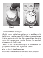
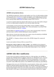
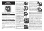
RadioLINK Module
for Battery Powered
Carbon Monoxide Alarms
Ei207 & Ei208 Series
Ei200MRF Module
Instructions
Read and retain carefully for as long as the product is being used. It contains vital information on the operation and installation
of your Module. The leaflet should be regarded as part of the product.
If you are just installing this Module, the leaftet must be given to the householder. The leaflet is to be given to any subsequent
user.
Table of Contents
page
Introduction ................................................................................
3
Installation ................................................................................
3
Interconnection with RadioLINK Modules .................................
6
RadioLINK Troubleshooting .......................................................
7
Testing .......................................................................................
8
Getting your Alarm Serviced .....................................................
9
Guarantee ................................................................................
9
Technical Specification .............................................................
10
Contact Us ................................................................................
11
2
Introduction
Congratulations on purchasing an Ei200 Series RF RadioLINK module. This RF
module can be easily installed in the RF upgradeable Ei207 or Ei208 Series Carbon
Monoxide Alarms to provide you with an RF interconnected warning system – when
one Alarm senses carbon monoxide gas and sounds a warning, all the other Alarms
will also sound a warning. This helps to ensure the alarm sound will be heard
throughout the property.
Installation
1. The Ei200 Series Carbon Monoxide Alarm must be installed as per the guidance
in the instruction booklet ‘Battery Powered Carbon Monoxide Alarms Ei207/
Ei208 Series’.
It is advisable that all RadioLINK Carbon Monoxide Alarms should be installed
(where possible) with the antennas (see figure 2) in the same orientation (i.e.
essentially parallel). This means picking a part of the building, say the front wall
of the building and then installing all mounting plates in the same orientation with
respect to this.
2. Remove the RF module from the packaging, carefully insert into the back of the
Alarm (see figure 1). Fold over the pull tag and fit the antenna in to the slot provided
(see figure 2).
House code the Alarms as follows:
3. Before fitting the Alarm to the mounting plate, press and hold the ‘House Code’
button on the rear of the RadioLINK module until the blue light comes on (see figure
2) and then release.
3
fold over
pull tag
House
Code Button
Blue
Light
Antenna
Figure 1
Figure 2
4. Twist the Alarm onto its mounting plate.
5. Similarly press and hold the House Code button on the second Alarm until its
blue light comes on and then release. Twist the Alarm onto its mounting plate.
Put all the remaining Alarms into House Code mode similarly and attach to the
mounting plate in the same manner in less than 15 minutes. (They automatically
exit house code mode after 30 minutes).
6. When in the House Code mode, the blue light (on the front of the Alarm - see
figure 3) will flash a number of times every 5 seconds to indicate:
(a) that the Alarm is in House Code mode, and
(b) the number of Alarms that have been identified and added to your system.
4
For example with 3 Alarms in your system,
you should see 3 blue light flashes every 5
seconds, with 4 Alarms in your system you
should see 4 blue light flashes and so on,
(with the 10th unit, the blue flash is longer,
to help with the counting of the flashes).
Allow sufficient time for all the alarms in
the system to be identified.
Check that the number of blue light flashes
corresponds to the number of Alarms in
the system. If not see the “RadioLINK
Troubleshooting” section below.
Blue RF
Light
Test
Button
Figure 3
7. The Alarms will stay in House Code mode for 30 minutes and then exits
automatically. Alternatively they can be taken out of House Code mode by removing
one Alarm from its mounting plate and quickly pressing and holding the House Code
button until the blue light comes on solidly again. Release the button and the blue light
will go out after 4 seconds, indicating that the Alarm is no longer in House Code mode.
Replace the Alarm on the mounting plate. The blue light will no longer be flashing.
As this Alarm exits house code mode it sends a radio message to all the other
Alarms to exit the house code mode (i.e. there is no need to physically remove each
Alarm from house code mode). Visually, check that all the blue lights on the rest of
the Alarms have ceased flashing.
8. Press the Test Button (see figure 3) on all the Alarms in turn and check all the
other Alarms are sounding at the same time. If they are not all communicating see
section below “RadioLINK Troubleshooting”.
5
Interconnection with RadioLINK Modules
A maximum of 12 Alarms with RF RadioLINK Modules may be interconnected so
that if one of the Alarms senses carbon monoxide gas, and sounds a warning, all the
other Alarms will also sound a warning. This helps to ensure the alarm will be heard
throughout the property.
As a safety feature, the Alarms fitted with the RF module, will communicate with each
other using the default RF signal. However, to avoid other neighbouring systems
setting off your Alarms and vice versa, we recommend that you “House Code” your
Alarm system.
Another very important reason for house coding is that after the Alarms are house
coded, they all act as “repeaters” i.e. they repeat the messages from other Alarms
and so greatly improve the reliability and range of the radio communication.
Additional RadioLINK Alarms can be added to the system at any time. Simply put all
the Alarms into the House Code mode at the same time and again check the number
of blue light flashes on each Alarm.
These RadioLINK Alarms should be interconnected only within the confines of a
single family living residence. If they are connected between different residences
there may be excessive nuisance alarms. Everybody may not be aware that they
are being tested.
6
RadioLINK Troubleshooting
It is imperative that all Alarms in your system communicate with each other. The
number of walls, ceilings and metal objects in the signal path reduces the strength
of the RadioLINK signals between the Alarms. Accordingly, one or more Alarms
may have difficulties in communicating to all the other Alarms in the system. If, when
checking the RadioLINK interconnection, some of the Alarms do not respond to the
button test, then you will need to either:
(i) Position another RadioLINK Alarm to act as a ‘repeater’ (see Interconnection
with RadioLINK Modules below) between the Alarms which are not communicating
and so shorten the path and/or by-pass an obstacle which is blocking the signal.
When the new Alarm is fitted, house code all Alarms again, as described above.
(ii) rotate / re-locate the units (e.g. move them away from metal surfaces or wiring).
After making these changes to the RF signal path, the RadioLINK signals may still
not be reaching all the Alarms in your system, even though they have already been
House Coded successfully. (see Section on “RadioLINK Limitations”).
It is important to check that all Alarms are communicating in their final installed
positions. If Alarms are rotated and/or resited, we would recommend that all the
Alarms are returned to the default settings and then House Coded again in their
final positions (see above). The RadioLINK interconnection should then be checked
again by button testing all units.
The RadioLINK module can be returned to the originally default settings by pressing
and holding the House Code button on until the blue light turns on solidly and then
flashes slowly. This will take about 10 seconds. This clears any previous House
Code settings.
7
Testing
Your Alarm is a life saving device and should be checked periodically.
Manually Testing your Alarms
It is recommended that you test your Alarms after installation and then at least
weekly to ensure the units are working. It will also help you and your family to
become familiar with the sound of the Alarms.
- Press and hold the Test Button until the Alarm sounds.
The sound output of the first cycle is reduced to facilitate easier testing. The second
cycle quickly reaches maximum sound output. The Alarm will stop sounding shortly
after the button is released.
- If they are interconnected using RadioLINK modules, hold down the Test button
until the blue light on the cover of the Alarm illuminates (see figure 3). Check that
all other Alarms sound.
- Release the Test button. The Alarm and all connected Alarms should stop
sounding.
- Repeat this procedure for all other Alarms in the system.
Limitations of RadioLINK Radio Frequency Signals
Ei Electronics radio communication systems are very reliable and are tested to high
standards. However, due to their low transmitting power and limited range (required
by regulatory bodies) there are some limitations to be considered:
(i) Receivers may be blocked by radio signals occurring on or near their operating
frequencies, regardless of the House Coding.
8
(ii) Alarms with RadioLINK modules should be tested regularly, at least weekly.
This is to determine whether there are sources of interference preventing
communication, that the radio paths have not been disrupted by moving furniture
or renovations, and if so, to give a warning of these and other faults.
Getting Your Alarm Serviced
If your Alarm fails to work after you have read the sections on “Installation”, “Testing”
and “Troubleshooting”, then contact Customer Assistance at the nearest address
given at the end of this leaflet. If it needs to be returned for repair or replacement put
it in a padded box with the batteries disconnected. Send it to “Customer Assistance”
at the nearest address given on the Alarm or in this leaflet. State the nature of the
fault, where the Alarm was purchased and the date of purchase.
Five Year Guarantee
Ei Electronics guarantees this RF RadioLINK Module for five years from date of
purchase against any defects that are due to faulty materials or workmanship.
This guarantee only applies to normal conditions of use and service, and does not
include damage resulting from accident, neglect, misuse, unauthorised dismantling,
or contamination howsoever caused. This guarantee excludes incidental and
consequential damage. If this RF RadioLINK Module should become defective
within the guarantee period, it must be returned to Ei Electronics, with proof of
purchase, carefully packaged, with the problem clearly stated. We shall at our
discretion repair or replace the faulty unit.
Do not interfere with the Alarm or attempt to tamper with it. This will invalidate the
guarantee, but more importantly may expose the user to shock or fire hazards.
This guarantee is in addition to your statutory rights as a consumer.
9
Technical Specification
Operating Freq:
868.499MHz +/- 20 kHz
Output power:
10dBm (nom)
Range:
250m in free air (min)
Protocol:
Radiolink
Alarm Transmit Interval:
10 sec
Initial Alarm duration:
3.5 sec
Short Alarm duration:
50 ms
Status Message duration: 50 ms
Weight:
8 grams
10
Contact Us
Aico Ltd. Mile End Business Park, Maesbury Rd, Oswestry,
Shropshire SY10 8NN, U.K.
Tel: 0870 758 4000
www.aico.co.uk
Ei Electronics. Shannon, Co Clare, Ireland. Tel: 061 471277
www.eielectronics.com
Block E1
The crossed out wheelie bin symbol that is on your
product indicates that this product should not be disposed
of via the normal household waste stream. Proper
disposal will prevent possible harm to the environment or
to human health. When disposing of this product please
separate it from other waste streams to ensure that it can
be recycled in an environmentally sound manner. For
more details on collection and proper disposal, please
contact your local government office or the retailer where
you purchased this product.
11
© Ei Electronics 2011
P/N B17161 Rev 0