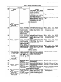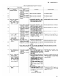
1
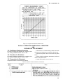
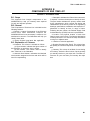
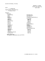
TM 11-6625-2611-12
TECHNICAL MANUAL
OPERATOR’S AND ORGANIZATIONAL MAINTENANCE MANUAL
TEST SET, TRANSPONDER SET
AN/APM-305A
HEADQUARTERS, DEPARTMENT OF THE ARMY
JUNE 1978
TM 11-6625-2611-12
T ECHNICAL M A N U A L
No. 11-6625-2611-12
HEADQUARTERS
DEPARTMENT OF THE ARMY
W As HINGTON , DC 5 June 1978
OPERATOR’S AND ORGANIZATIONAL MAINTENANCE MANUAL
TEST SET, TRANSPONDER SET AN/APM-305A
REPORTING OF ERRORS
You can improve this manual by recommending improvements using DA Form 2028-2 (Test)
Iocated in the back of the manual. Simply tear out the self-addressed form, fill it out as shown on
the sample, fold it where shown, and drop it in the mail.
If there are no blank DA Form 2028-2 (Test) in the back of your manual, use the standard DA
Form 2028 (Recommended Changes to Publications and Blank Forms) and forward to the Commander, US Army Communications and Electronics Materiel Readiness Command, ATTN
DRSEL-MA-Q, Fort Monmouth, NJ, 07703.
In either case a reply will be furnished direct to you.
I
C HAPTER
Section
1.
I.
II.
CHAPTER
Section
2.
I.
II.
HI.
IV.
C HAPTER
Section
3.
I.
II.
C HAPTER
4.
Paragraph
INTRODUCTION
General
Scope . . . . . . . . . . . . . . . . . . . . . . . . . . . . . . . . . . . . . . . . . . . . . . . . . . . . . . . . . . . . . . . . . . . . . . . . . . . . . . . . . . . . . . . . . . . . . . . 1-1
Indexes of Publications . . . . . . . . . . . . . . . . . . . . . . . . . . . . . . . . . . . . . . . . . . . . . . . . . . . . . . . . . . . . . . . . . . . . . . . . . . . . . . 1-2
Forms and Records . . . . . . . . . . . . . . . . . . . . . . . . . . . . . . . . . . . . . . . . . . . . . . . . . . . . . . . . . . . . . . . . . . . . . . . . . . . . . . . . . . 1-3
Administrative Storage . . . . . . . . . . . . . . . . . . . . . . . . . . . . . . . . . . . . . . . . . . . . . . . . . . . . . . . . . . . . . . . . . . . . . . . . . . . . . . 1-4
Destruction of Army Electronics Matinal... . . . . . . . . . . . . . . . . . . . . . . . . . . . . . . . . . . . . . . . . . . . . . . . . . . . . . . . . . . 1-5
Calibration . . . . . . . . . . . . . . . . . . . . . . . . . . . . . . . . . . . . . . . . . . . . . . . . . . . . . . . . . . . . . . . . . . . . . . . . . . . . . . . . . . . . . . . . . 1-6
Reporting Equipment Improvement Recommendations . . . . . . . . . . . . . . . . .. . . . . . . . . . . . . . . . . . . . . . . . . . . . . . . . .1-7
Description and Data
Purpose and Use . . . . . . . . . . . . . . . . . . . . . . . . . . . . . . . . . . . . . . . . . . . . . . . . . . . . . . . . . . . . . . . . . . . . . . . . . . . . . . . . . ...1-8
Description . . . . . . . . . . . . . . . . . . . . . . . . . . . . . . . . . . . . . . . . . . . . . . . . . . . . . . . . . . . . . . . . . . . . . . . . . . . . . . . . . . . . . . . . . 1-9
Tabulated Data . . . . . . . . . . . . . . . . . . . . . . . . . . . . . . . . . . . . . . . . . . . . . . . . . . . . . . . . . . . . . . . . . . . . . . . . . . . . . . . . . . ...1-10
Items Comprising and Operable Equipment. . . . . . . . . . . . . . . . . . . . . . . . . . . . . . . . . . . . . . . . . . . . . . . . . . . . . . . . . . . 1-11
SERVICE UPON RECEIPT AND INSTALLATION
Semite Upon Receipt of Materiel Siting . . . . . . . . . . . . . . . . . . . . . . . . . . . . . . . . . . . . . . . . . . . . . . . . . . . . . . . . . . . . . . 2-1
Unpacking . . . . . . . . . . . . . . . . . . . . . . . . . . . . . . . . . . . . . . . . . . . . . . . . . . . . . . . . . . . . . . . . . . . . . . . . . . . . . . . . . . . . . . . . . . 2-2
Checking Unpacked Equipment . . . . . . . . . . . . . . . . . . . . . . . . . . . . . . . . . . . . . . . . . . . . . . . . . . . . . . . . . . . . . . . . . . . . . . 2-3
Installation Instructions Tools, Test Euipment, and Materials Required for Installation . . . . . . . . . . . . . ...2-4
Assembly of Equipment . . . . . . . . . . . . . . . . . . . . . . . . . . . . . . . . . . . . . . . . . . . . . . . . . . . . . . . . . . . . . . . . . . . . . . . . . . . ...2-5
Installation procedures . . . . . . . . . . . . . . . . . . . . . . . . . . . . . . . . . . . . . . . . . . . . . . . . . . . . . . . . . . . . . . . . . . . . . . . . . . . . . . 2-6
Interconnections . . . . . . . . . . . . . . . . . . . . . . . . . . . . . . . . . . . . . . . . . . . . . . . . . . . . . . . . . . . . . . . . . . . . . . . . . . . . . . . . . . . . 2-7
Preliminary Adjustment of Equipment
Operator’s Controls, Indicators, and Connectors . . . . . . . . . . . . . . . . . . . . . . . . . . . . . . . . . . . . . . . . . . . . . . . . . . . . . . . . 2-8
Typical Bench Setup ......... . . . . . . . . . . . . . . . . . . . . . . . . . . . . . . . . . . . . . . . . . . . . . . . . . . . . . . . . . . . . . . . . . . . . . ...2-9
Additional Test Capabilities . . . . . . . . . . . . . . . . . . . . . . . . . . . . . . . . . . . . . . . . . . . . . . . . . . . . . . . . . . . . . . . . . . . . . . . ...2-l0
Circuit Alignment
Introduction . . . . . . . . . . . . . . . . . . . . . . . . . . . . . . . . . . . . . . . . . . . . . . . . . . . . . . . . . . . . . . . . . . . . . . . . . . . . . . . . . . . . . . . . 2-11
General Information . . . . . . . . . . . . . . . . . . . . . . . . . . . . . . . . . . . . . . . . . . . . . . . . . . . . . . . . . . . . . . . . . . . . . . . . . . . . . . . . . 2-12
OPERATING INSTRUCTIONS
Controls and Instruments
Damage From Improper Settings . . . . . . . . . . . . . . . . . . . . . . . . . . . . . . . . . . . . . . . . . . . . . . . . . . . . . . . . . . . . . . . . . . . . . 3-1
Operator’s Controls . . . . . . . . . . . . . . . . . . . . . . . . . . . . . . . . . . . . . . . . . . . . . . . . . . . . . . . . . . . . . . . . . . . . . . . . . . . . . . . ...3-2
Operation Under Unusual Conditions and Preparation for Movement
preliminary Starting Procedure . . . . . . . . . . . . . . . . . . . . . . . . . . . . . . . . . . . . . . . . . . . . . . . . . . . . . . . . . . . . . . . . . . . . . . 3-3
procedure for Shutdown . . . . . . . . . . . . . . . . . . . . . . . . . . . . . . . . . . . . . . . . . . . . . . . . . . . . . . . . . . . . . . . . . . . . . . . . . . . . . . 3-4
Preparation for Movement . . . . . . . . . . . . . . . . . . . . . . . . . . . . . . . . . . . . . . . . . . . . . . . . . . . . . . . . . . . . . . . . . . . . . . . . . . 3-5
OPERATOR/CREW MAINTENANCE INSTRUCTIONS
Tools and Equipment . . . . . . . . . . . . . . . . . . . . . . . . . . . . . . . . . . . . . . . . . . . . . . . . . . . . . . . . . . . . . . . . . . . . . . . . . . . . . . . . 4-1
Lubrication . . . . . . . . . . . . . . . . . . . . . . . . . . . . . . . . . . . . . . . . . . . . . . . . . . . . . . . . . . . . . . . . . . . . . . . . . . . . . . . . . . . . . . . . . 4-2
Preventive Maintenance Checks and Services . . . . . . . . . . . . . . . . . . . . . . . . . . . . . . . . . . . . . . . . . . . . . . . . . . . . . . . ...4-3
Page
1-1
1-3
1-3
1-3
1-3
1-3
1-3
1-3
1-3
1-4
1-5
2-1
2-1
2-2
2-3
2-3
2-3
2-3
2-3
2-3
2-5
2-5
2-5
3-1
3-1
3-3
3-3
3-3
4-1
4-1
4-1
i
TM 11-6625-2611-12
Paragraph
Page
4-1
4-1
4-1
4-1
4-2
4-2
4-5
4-12
CHAPTER 4 (cont.) Preventive Maintenanc e . . . . . . . . . . . . . . . . . . . . . . . . . . . . . . . . . . . . . . . . . . . . . . . . . . . . . . . . . . . . . . . . . . . . . . . . . ...4-4
Preventive Maintenance and Service Periods... . . . . . . . . . . . . . . . . . . . . . . . . . . . . . . . . . . . . . . . . . . . . . . . . . . . . ...4-5
Daily Preventive Maintenance Checks and Service Periods . . . . . . . . . . . . . . . . . . . . . . . . . . . . . . . . . . . . . . . . . . . ...4-6
Weekly Preventive Maintenance Checks and Services . . . . . . . . . . . . . . . . . . . . . . . . . . . . . . . . . . . . . . . . . . . . . . . . ...4-7
Quarterly Preventive Maintenance Checks and Services . . . . . . . . . . . . . . . . . . . . . . . . . . . . . . . . . . . . . . . . . . . . . . . ..4-8
Quarterly Test Procedure . . . . . . . . . . . . . . . . . .. . . . . . . . . . . . . . . . . . . . . . . . . . . . . . . . . . . . . . . . . . . . . . . . . . . . . . . . 4-9
General Troubleshooting Information . . . . . . . . . . . . . . . . . . . . . . . . . . . . . . . . . . . . . . . . . . . . . . . . . . . . . . . . . . . . . . . . .4-10
Troubleshooting Chart . . . . . . . . . . . . . . . . . . . . . . . . . . . . . . . .. . . . . . . ... 4-11
ORGANIZATIONAL MAINTENANCE INSTRUTIONS
C HAPTER 5 .
5-1
General . . . . . . . . . . . . . . . . . . . . . . . . . . . . . . . .5.1
5-1
Cleaning . . . . . . . . . . . . . . . . . . . . . . . . . .
.. .
5-2
5-1
Touchup Painting Instrutions . . . . . . . . . . . . . . . . . . . . . . . . . . . . . . . . . . . . . . . . . . . . . . . . . . . . . . . . . . . . . . . . . . . . ...5-3
5-1
Replacement of POWER Indicator Lamp . . . . . . . . . . . . . . . . . . . . . . . . . . . . . . . . . . . . . . . . . . . . . . . . . . . . ...5-4
5-1
Replacement of POWER DC FAULT Indicator Lamp . . . . . . . . . . . . . . . . . . . . . . . . . . . . . . . . . . . . . . . . . . . . . . . . ...5.5
5-1
Replacement of fuse . . . . . . . . . . . . . . . . . . . . . . . .5-6
5-1
Minor Repair of Cables . . . . . . . . . . . . . . . . . . . . . . . . .5-7
5-1
CHAL AUX MOD DLY Knob Adjustment . . . . . . . . . . . . . . . . . . . . . . . . . . . . . . . . . . . . . . . . . . . . . . . . . . . . . . . . . . ...5-8
5-2
Knob Replacement . . . . . . . . . . . . . . . . . . . . . . . . . .5-9
A P P E N D I X A . REFERENCES . . . . . . . . . . . . . . . . . . . . . . . . . . . . . . . . . . . .. A-l
B. COMPONENTS OF END ITEM LIST . . . . . . . . . . . . . . . . . . . . . . . . . . . . . . . . . . . . . . . . . . . . . . . . . . . . . . . . .. . . . . . . . . . . . . . . . .
Section
I. Introduction . . . . . . . . . . . . . . . . . . . . . . . . . . . . . . . . . ..B-1
II. Integral Components of End Item . . . . . . . . . . . . . . . . . . . . . . . . . . . . . . . .. . . . . . . . . . . . . . . . . . . . . . . B-2
A P P E N D I X C . ADDITIONAL AUTHORIZATION LIST (Not applicable)
MAINTENANCE ALLOCATION
A PPENDIX D .
Section
I. Introduction . . . . . . . . . . . . . . . . . . . . . . . . . . . . . . . . . ..D-1
II. Maintenance Allocation Chart for TEST SET, TRANSPONDER SET AN/APM-305A . . . . . . . . . . . . . . . . . . . . . . . . . . . . . .D-3
III. Tool and Test Equipment Requirements for Transponder Set, Test Set AN/APM-305A . . . . . . . . . . . . . . . . . . . . . . . . . . . . . .D-5
A P P E N D I X E . EXPENDABLE SUPPLIES AND MATERIALS LIST
Section
I. Introduction . . . . . . . . . . . . . . . . . . . . . . . . . . . . . . ..E-1
II. Expendable Supplies and Materials List. . . . . . . . . . . . . . . . . . . . . . . . . . . . . . . . . . . . . . . . . . . . . . . . . . . . . . . . . . . . . . . . . . . . . . . ..E-2
ii
TM 11-6625-2611-12
CHAPTER 1
INTRODUCTION
Section I. GENERAL
1-1. Scope
This manual describes Test Set, Transponder Set
AN/APM-305A (test set) (fig. 1-1) and covers its operation and organizational maintenance. It includes in-
structions for installation, operation, inspection, selftesting, and preventive maintenance of the equipment.
Also included in this manual is a maintenance allocation chart (app D).
1-1
Cover Assy Test Set MX-9944/APM305A (152050)
Test Set Transponder TS-3395 A/APM305 (152100)
Attenuator, 30 dB (134645-2)
Cable Assy, RF (Jumper) (139528)
Attenuator, 15 dB (134645-1)
Chart, Conversion RF (151944-1)
TM 11-6625-2611-12
1
2
3
4
5
6
1-2
Figure 1-1.
7 Adapter C (male) to N (female) (UG-565 A/U)
8 Termination, Feedthru, 75 ohm (134646-1)
9 Termination Feedthru, 93 ohm (134646-2)
10 Cable Assy, Video (139527)
11 Cable Assyt RF (139526)
12 Cable Assy, Power, AC (139529)
TM 11-6625-2611-12
1-2. Indexes of Publications
P4610.19C and DLAR 4500.15.
a. DA Pam 310-4. Refer to the latest issue of DA
Pam 310-4 to determine whether there are new editions, changes, or additional publications pertaining to
the equipment.
b. DA Pam 310-7. Refer to DA Pam 310-7 to determine whether there are modification work orders
(MWO’S) pertaining to the equipment.
1-4. Administrative Storage
Administrative storage of equipment issued to and
used by Army activities shall be in accordance with TM
740-90-1.
1-3. Forms and Records
a. Reports of Maintenance and Unsatisfactory
Equipment. Maintenance forms, records, and reports
which are to be used by maintenance personnel at all
maintenance levels are listed in and prescribed by TM
38-750.
b. Report of Packaging and Handling Deficiencies.
Fill out and forward DD Form 6 (Packaging Improvement Report) as prescribed in AR
700-58/NAVSUPINST
4030.29/AFR
71-13/MCO
P4030.29A, and DLAR 4145.8.
c. Discrepancy in Shipment Report (DISREP) (SF
361). Fill out and forward Discrepancy in Shipment
Report (DISREP) (SF 361) as prescribed in AR
55-38/NAVSUPINST
4610.33B/AFR
75-18/MCO
1-5. Destruction of Army Electronics
Materiel
Destruction of Army electronics materiel to prevent
enemy use shall be in accordance with TM 750-244-2.
1-6. Calibration
Pertinent publications on calibration of this equipment
is referenced in TM 11-6625-2611-35.
1-7. Reporting Equipment Improvement
Recommendations (EIR)
EIR’s will be prepared using DA Form 2407, (Maintenance Request). Instructions for preparing EIR’s are
provided in TM 38-750, The Army Maintenance Management System. EIR’s should be mailed direct to US
Army Communications and Electronics Materiel
Readiness Command, ATTN. DRSEL-MA-Q, Fort
Monmouth, New Jersey 07703. A reply will be furnished direct to you.
Section Il. DESCRIPTION AND DATA
1-8. Purpose and Use
The test set is a bench test set which when used with an
oscilloscope and Test Set, Transponder Set
AN/APM-239 provides field personnel with the
capability to check, maintain, align and calibrate
transponder sets which meet the requirements of DODAIMS 65-1000. The test set generates IFF interrogations and transmits these signals at adjustable rf
power levels and adjustable prf to the transponder
under test. Two separate variable rf outputs are provided to test diversity type transponders, or the two rf
paths can be combined to test transponder ISLS
characteristics over the complete dynamic range of the
transponder. The rf reply from the transponder is
demodulated and can be analyzed for proper frequency,
power level, coding, pulse shape and pulse train spacing. Mode 4 operation, including disparity conditions,
can be simulated. Facilities are included to test the
selectivity of the transponder received and suppression pulse circuits; and supply crystal controlled
markers to the oscilloscope. A self-test feature permits
isolation of failures to a printed circuit card and/or
module level using only the test set indicators and test
points.
1-9. Description
The test set generates the necessary signals to test
transponder sets and converts rf signals generated by
the transponder set into video signals which are applied to the oscilloscope for display. The test set consists of the items listed in paragraph 1-12. All items of
the test set are described in the following subparagraphs.
a. Test Set, Transponder TS-3395A/APM-305.
TS-3395A/APM-305 contains all the active circuits of
the test set. All circuits and their related components
are mounted on a common chassis, which is enclosed in
a dust cover. All connectors, controls, indicators, and
1.0 ampere fuse are located on the front panel. All controls are directly calibrated. Two vertically positioned
handles, which act as guardrails, are located at the extreme ends of the front panel. As indicator lamp indicates that the test set is energized. A second indicator
indicates when the power supply fails. A meter is provided with dual calibration to measure rf peak power
and prf. The weight and overall dimensions of the test
set are listed in paragraph 1-12.
b. Test Set Cover MX-99441APM-305A. Test Set
Cover MX-9944/APM-305A (front panel cover) attaches to the front panel of the test set to protect it
when not in use. All accessories are within the front
panel cover. The front panel cover attaches to the test
set by four latches.
c. Power Cable Assembly. The three-conductor
power cable assembly connects the test set to a 115 vac
primary power source. One end of power cable assembly has an MS3016E1OSL-3S connector. This connector
is to be connected to the test set POWER connector.
The other end of power cable assembly has a UP-131M
connector connected to the primary power source. The
ground pin of the connector is spring-loaded to the in1-3
TM 11-6625-2611-12
use position. Normally, the ground pin is connected to
power ground. However, if the ground system of the
transponder under test is other than the power ground,
the ground pin is pivoted to the not-in-use position
when the plug is inserted into the power receptacle.
The overall length and weight of power cable assembly
are listed in paragraph 1-12.
d. Adapters. Two Adapters UG-565A/U are provided as a means of mating the rf cable assembly to
transponders with female type C rf connectors, such as
UG-571/U. The overall dimensions and weight of
Adapter UG-565A/U are listed in paragraph 1-12.
e. Rf Cable Assembly, 12 Inch (50.48CM). The rf cable assembly is used to connect the test set RF IN/OUT
jacks to the LOW PWR IN jack during self-checks. The
type of cable used is RG-223/U. One end of the rf cable
assembly has a male type BNC (UG-88/U) connector.
This end of rf cable assembly mates with the test set
LOW PWR IN jack. The other end of the rf cable assembly has a male type N connector which mates with
either test set RF IN/OUT jack. The overall length and
weight of rf cable assembly are listed in paragraph
1-12.
f. Video Cable Assemblies, 60 Inch (152.4 CM).
Four video cable assemblies are provided to interconnect the test set to the oscilloscope. Video cable assemblies are constructed of RG-62A/U cable. Each end of
the cable assemblies has a male type BNC (UG-88/U)
connector. The overall length and weight of the video
cable assemblies are listed in paragraph 1-12.
g. Rf Cable Assemblies, 96.0 Inch (243.84 CM). Two
rf cable assemblies are provided to interconnect the
test set RF IN/OUT jacks to the transponder rf jacks.
Each cable is made of a calibrated length of RG-212/U.
The attenuation of the rf cable assembly is marked on
the cable (usually 0.9 db) for either 1030 MHz or 1090
MHz which must be added to the test set attenuator
setting when determining the output signal of the test
set. The attenuation must also be considered when
measuring the rf output power of the transponder set
under test. Each end of rf cable assembly has a male
type N connector for mating with a female type N connector such as UG-19B/U. The overall length and
weight of the rf cable assembly are listed in paragraph
1-12.
h. 15 and 30 Db Attenuators. The attenuators are
used to extend the input power capability of the test set
LOW PWR IN jack to a range between +3 dbm and
+48 dbm. Each attenuator is individually calibrated
with the actual attenuation marked on the side. One
end of the attenuator has a male type BNC connector
which mates with the test set LOW PWR IN jack. The
other end of the attenuator has a female type BNC connector which mates with a UG-88/U connector attached to an rf cable. The overall dimensions and
weight of the attenuators are listed in paragraph 1-12.
1-4
L Conversion Chart The conversion chart is used to
convert test set power meter indications in dbw into
power inputs in KW. Meter indications are read on the
bottom of the chart and power is read along the side.
The dimensions of the calibration chart are listed in
paragraph 1-12.
j. Video Terminations. Three feedthrough-type terminations are provided, each with a connector on one
end to mate with a UG-912/U and a connector on the
other end to mate with a UG-260/U. The dc resistance
of two of the terminations is 75 ohms and the remaining termination is 93 ohms. The 75-ohm terminations
(MX-554 A/U) provide proper termination of demodulated and reply marker test set outputs. The 93-ohm
termination (MX-554 A/U) provides proper termination of mode 4 reply output.
1-10. Tabulated Data
Parameter
Internal PRF:
Reduced PRF:
RF Sweep PRF:
Scope Trigger Output
Auxiliary Trigger Output:
Codes:
Challenge Pulse Spacing
Mode 4 Pulse Spacing (2nd 3rd,
and 4th sync pulses):
Challenge Pulse Width:
ILSL Pulse Spacing
Suppression Pulse Output:
Mode 4 Enable Trigger Input
Mode 4 Challenge Video Input
Mode 4 Reply Output:
Mode 4 Disparity Output:
SIF Markers:
Timing Markers
Description
10 to 10,000 pps for SIF
5 to 5,500 pps
250 Hz and 800 Hz, ±10 percent
5±1V, positive, 3 ±2 µ sec,100
ohms, 0.5 to 4000 µ sec variable delay
20 ± 3V, positive, 1 ± 0.5 µ see,
90 ohms
1, 2, 3/A, C, Test, Mode 4 words
A and B
Nominal, ±0.2, ±0.9 µ sec
(±0.05 µ sec) and Variable
±1µsec
Nominal, ±0.2, ±0.9 µsec
(±0.05 µ see) and Variable
±1 µsec
0.25, 0.5, 0.8, 1.7 µ sec (±0.05
µ sec) and Variable from 0.25
to 1.7 µ sec
Nominal, ±0.15, ±0.6 µ sec
(±0.05 µ see) and Variable
±1µsec
20 ± 2 V, positive, 30 ±3 µ sec,
2200 ohms, <50 picofarad
1.5 to 5 V, positive, 0.5 to 3 µ sec,
90 ohms
1.5 to 5V, positive, 0.4 to 0.6
µ see, 90 ohms
5 ±0.5V, positive, 0.5 ±0.1
µ sec, 3 pulses spaced 1.8
±0.1 µ sec, 90 ohms, 200 µ sec
after fourth sync pulse
5 ±0.5V, positive, 0.5 ±0.1
µ sec, 90 ohms, 65 ±1 µ sec
after enable trigger or coincident with the pulse at 66 µ sec
for Mode 4 (word A and B)
Disparity
0, 20.30, 24.65 and 49.30 µ sec
(±0.02 µ sec), Variable from 2
to 4 µ sec after P3; > .5V positive, 0.15 ±0.05 µ sec, 75
ohms
0.1, 1.0, and 10.0 µ sec ±.02%,
TM 11-6625-2611-12
Parameter
Signal Generator Fixed Frequency Output:
Signal Generator Swept Frequency Output:
Swept Frequency Markers:
RF Power Output (Main or Aux)
Fixed Frequency with pulse
width of 0.5 to 0.8 µ sec
Operation Limitations:
Temperature
Altitude
ISLS Output Level:
RF Input (Main or Aux)
Demodulated Video:
Qty
1
NSN
2
5935-00-665-6543
1
1
1
1
4
2
1
2
1
1
Parameter
Description
>05 volts 75 ohms
1030 MHz ±0.01 percent
1025 to 1035 MHz or 1010 to
1050 MHz
1025, 1027, 1029, 1030, 1031,
1033, 1035 MHz ±0.1 MHz
and 1010, 1050 MHz ±0.3
MHz
-10 to -90 dbm ±1.0 db
-10 to -90 dbm ±1.0 db
00c to +55°C
0 to 10,000 feet (3048 meters)
above sea level
Variable from 0 to -70 dB from
Main RF output (-90 dbm
minimum)
63 W to 2.0 KW Peak 14W avg.,
VSWR less than 1.35:1 within 50 ohm load
> 1V for +18 to 33 dBw, with
Item
Test Set, Transponder
TS-3395A/APM-305A
NOTE
Following items
are stored inside
test set cover.
Connector
Adapter,
UG-565A/U
attenuator
15 db
(45413-134645-1)
30 db Attenuator (TE
134645-2)
CabIe assembly, power
(45413-139529)
Cable assembly, rf
(45413-139528)
Cable assembly, video
(45413-139527)
Cable assembly, rf
(45413-139526)
chart
Conversion
(45419-151944-1)
Termination feedthru
750 (134646-1)
Termination feedthru
93 (134646-2)
Set
Test
Cover,
Mx-9944/APM-305A
(152060)
Power Measurement (Main or
Aux)
Low Power Measurement:
Frequency Measurement:
PRF Measurement (Demodulated Replies or Internal
Trigger)
Meter
Input Power
Description
less than 20 µ sec distortion,
1085 to 1095 MHz
+18 dBw to + 33 dBw ± dB
-12 dBm to +3 dBm ±1 dB
±0.6 MHz accuracy, 1070.0
MHz to 1086.9 MHz, and
1093.1 MHz to 1110.0 MHz,
± 0.2 MHz, 1087.0 MHz to
1093.0 MHz
5 to 10.000 Hz
Reads PRF in Hz and Power in
dBw
103.5 to 126.5 vat, 45 to 66 Hz or
380 to 420 Hz, 70 Watts
1-11. Items Comprising an Operable Equipment
The items of the test set required for operation are
listed below.
Height
13.98 (35.50CM)
Dimensions(in.)(cm)
Width
18.0 (45.72cm)
1.375 lb (3.49CM)
0.75 dia (1.9cm)
Depth
15.5 (39.37cm)
Weight(lb)(gr)
54 (24.3 kg)
0.125 (56.7 gr)
1.9375 Ig (4.92CM) 0.5625 dia (1.42cm)
0.62 (281.23 gr)
1.9375 lb (4.92cm) 0.5625 dia (1.42cm)
0.62 (281:23 gr)
96.0 lg (243.84cm)
0.30 (136.08 gr)
12.0 }g (30.48cm)
0.125 (56.7 gr)
60.0 lg (152.4cm)
0.25 (113.4 gr)
96.0 lg (243.84cm)
0.95 (430.92 gr)
5.50 lg (13.97cm)
0.01 (4.536 gr)
4.50 (11.43cm)
0.30 (136.08 gr)
0.30 (136.08 gr)
4.01 (10.18cm)
17.19 (43.66cm)
13.5 (34.29cm)
5.0 (2.27 kg)
1-5
TM 11-6625-2611-12
CHAPTER 2
SERVICE UPON RECEIPT AND INSTALLATION
Section I. SERVICE UPON RECEIPT OF MATERIAL
2-1. Siting
The installation site shall have conditions which meet
the operating limitations characteristics described in
paragraph 1-11.
2-2. Unpacking
When packed for shipment, the test set is placed in a
corrugated box. A typical shipping box and its contents
are shown in figure 2-1. The outer corrugated box is 29
inches (73.66 cm) high, 18 3/4 inches (47.62 cm) deep, and
25 1/4 inches (64.13 cm) wide; the volume is 7.95 cubic
feet (.225 cu meter). The gross weight of the carton is 5
pounds (2.26 kg). Store shipping container and packing
material for future use.
2-1
TM 11-6625-2611-12
Figure 2-1. Packaging diagram
2-3. Checking Unpacked Equipment
a. Inspect the equipment for damage incurred during shipment. If the equipment has been damaged, report the damage on DD Form 6 (para 1-3).
b. Check the equipment against the component listing and the packing slip to see if the shipment is complete. Report all discrepancies in accordance with the
instructions in TM 38-750. The equipment should be
placed in service even though a minor assembly or part
2-2
that does not affect proper functioning is missing.
c. Check to see whether the equipment has km
modified. Equipment which has been modified will
have the MWO number on the front panel, near the nomenclature plate. Check also to see whether all currently applicable MWO’S have been applied. Current
MWO applicable to the equipment are listed in DA —
Pam 310-7.
TM 11-6625-2611-12
Section IL INSTALLATION INSTRUCTIONS
2-4. Tools, Test Equipment, and Materials
Required for Installation
place other equipment within 1 inch of either side of
the test set to allow for adequate cooling.
An oscilloscope only is required for installation, to view
output wave forms of test set.
2-7. Interconnections
2-5. Assembly of Equipment
secured to the test set by four latches, two on each side.
The test set is shipped assembled and ready for operation.
Remove the power cable from the front panel cover. Be
sure front panel POWER switch is OFF. Connect the
power cable between POWER connector and power
source (115 VAC, 45 to 66 or 380 to 420 Hz).
2-6. Installation Procedures
Place test set so that no forced-air cooling from other
equipment is directed on the sides of the test set. Do not
Remove the front panel cover. The front panel cover is
Section Ill. PRELIMINARY ADJUSTMENT OF EQUIPMENT
2-8. Operator’s Controls, Indicators, and
Connectors
Table 3-1 identifies and describes the functions of controls, indicators, and connectors of the test set. Figure
3-1 shows all controls, indicators, and connectors.
2-9. Typical Bench Test Setup
A typical bench test setup for making the following
transponder measurements is shown in figure 2-2.
a. Diversity characteristics
b. Receiver bandwidth and center frequency
c. Minimum triggering level at normal and low
sensitivity
d. Duty cycle limit
e . Reply rate limit
Mode 4 rate limit
f.
g. Internal suppression-decode
h Internal suppression~external
ISLS recognition
L
Decoder characteristics
j.
k. Pulse width discrimination
l.
m.
n.
o.
P.
q.
r.
s.
t.
u.
v.
w.
x.
y.
z.
aa.
ab.
ac.
ad.
ae.
Transmitter output frequency
Transmitter output power
Transmitter output pulse shape
Transponder delay
Transponder jitter
Reply code spacing and coding
I/P reply characteristics
Emergency reply characteristics
Auxiliary trigger operation
Mode C operation
Mode 4 reply characteristics
Disparity action
Mode 4 enable trigger output
Mode 4 video output
Mode 4 audio output
Mode 4 challenge video output
Mode 4 reply light enable
Mode 4 caution light enable
Random triggering rate
External suppression output
2-3
TM 11-6625-2611-12
Figure 2-2. Typical bench test setup.
2-4
TM 11-6625-2611-12
2-10. Additional Test Capabilities
In addition to performing the measurements listed in
paragraph 2-9, the test set can be used in a number of
test setup configurations to test other transponder
capabilities which include, but are not limited to, the
following
a. AOC reaction time
b. Internal suppression-ISLS
c. Preselector alignment
d. Echo suppression
e. ISLS gate characteristics
f. ISLS rate limit
Section IV. CIRCUIT ALIGNMENT
2-11. Introduction
This section contains the operator’s checklist to determine the operational status of the test set. Refer to table 2-4 for the checklist.
2-12. General Information
a. Use of Table. The operator’s checklist is a stepby-step test procedure and should be performed in the
order given. The Control settings column specifies the
settings of the equipment to be changed for the specific
measurement. The Test procedure column refers to the
applicable test setup and provides specific parameters
to be measured. The Performance standard column
specifies the results that should be observed. In all
steps, except steps 1 and 2, if the results specified are
not obtained, higher category maintenance is required.
If the results specified for steps 1 and 2 are not ob-
tained, refer to troubleshooting procedures in chapter
4. Waveforms are shown in figure 4-1.
b. Additional Equipment Required. The oscilloscope
is required to perform the operator’s checklist
procedures.
c. Oscilloscope Preparation for Use. To prepare the
oscilloscope for use, connect the power lead to 115 vac
power source. Make a connection between ground on
the oscilloscope and GND on the test set. Position controls as indicated in table 2-2.
d. Test Set Preparation for Use. To prepare the test
set for use, connect the power lead to 115 vac power
source. Connect the oscilloscope to the test set as shown
in figure 2-3. Set the remaining test set controls as
shown in table 2-3.
2-5
TM 11-6625-2611-12
Figure 2-3. Test set operator’8 checklist test setup
Table 2-3. Tent Set Preliminary Control Settings (Continued)
Table 2-2. Oscilloscope Control Settings
Controls
ON (applies ac power to
oscilloscope)
Adjust horizontal position for best
HORIZONTAL POSITION
display
HORIZONTAL MAGNIFIER X1
ALT
DISPLAY
1
A and B VOLTS/DIV
X1
MAGNIFIER
o
MAIN TRIGGER LEVEL
EXT + 10/ EXT/INT/LINE EXT
10 µ sec
MAIN TIME/DIV
SWEEP DISPLAY SWITCH MAIN
AUTO
SWEEP MODE
0.00
DIV DELAY
POWER (switch)
Table 2-3. Test Set Preliminary Control Settings
Settings
Controls
POWER ON/OFF switch
CHAL SUB PULSE SELECT switch
CHAL SUB PULSE POSITION
SELECT switch
CHAL SUB PULSE POSITION VARY
control
CHAL MODE SELECT switch
CHAL WIDTH SELECT switch
2-6
Settings
Controls
Settinq
ON
SIFP1
o
Midrange
c
0.80
CHAL WIDTH VARY control
CHAL ISIS SPACING SELECT switch
CHAL ISLS SPACING VARY control
CHAL INHIBIT switch
CHAL AUX MOD DLY control
MEASUREMENT PRF RANGE switch
FUNCTION
MEASUREMENT
SELECT switch
MEASUREMENT DEMOD VIDEO
LEVEL control
MEASUREMENT MKR PHASING
control
PRF SELECT RANGE switch
PRF SELECT MU LT control
PRF SELECT switch
SCOPE TRIG/FREQ MEAS DELAY
(USEC) RANGE switch
SCOPE TRIG/FREQ MEAS DELAY
(USEC) MULT control
SUPPR switch
AUX TRIG switch
MAIN ATTEN control
AUX ATTEN control
RF IN/OUT DEMOD switch
SIG GEN FCTN switch
Midrange
o
Midrange
OFF
Fully counterclockwise
X1K
PRF CHAL
Midrange
Midrange
X1K
5.0
X1
OFF
1.0
ON
ON
-10
-10
MAIN
FIXED FREQ
TM 11-6625-2611-12
2-7
TM 11-6625-2611-12
2-8
TM 11-6625-2611-12
2-9
TM 11-6625-2611-12
CHAPTER 3
OPERATING INSTRUCTIONS
Section I. CONTROLS AND INSTRUMENTS
3-1. Damage From Improper Settings
There are no control settings or combination of control
settings which will damage the equipment or create a
hazard to personnel.
3-2. Operator’s Controls
Table 3-1 identifies and describes the function of controls, indicators, and connectors of the test set. Figure
3-1 illustrates and locates all controls, indicators, and
connectors. Because of various transponder configurations, specific operating procedures for this test set are
not contained in this manual. Test procedures for a
specific transponder set are found in its associated
maintenance manual.
3-1
TM 11-6625-2611-12
3-2
Figure 3-1.
TM 11-6625-2611-12
Figure 3-2. Low power measurement calibration chart
Section Il. OPERATION UNDER USUAL CONDITIONS
AND
PREPARATION FOR MOVEMENT
3-3. Preliminary Starting Procedure
No special starting procedures are necessary other
than setting POWER ON/OFF switch to ON.
3-4. Procedure for Shutdown
No special stopping procedures are necessary other
than setting POWER ON/OFF switch to OFF.
3-5. Preparation for Movement
a. Disconnect all interconnecting cables from both
the test set and equipment
connected to the test set.
. b. Disconnect power cable from test set and power
source.
C. Store all cables, adapters, attenuators, loads, and
chart in front panel cover.
d. Install front panel cover to test set.
Prepare the test set for movement as follows:
Table 3-1. Operator’s Controls, Indicators, and Connectors
3-3
TM 11-6625-2611-12
Figure
3-1
index No
5
6
7
8
9
10
11
3-4
Table 3-1. Operator’s Controls, Indicators, and Connectors (Continued)
Control, indicatar,
Function
or
connector
tion between mode 3/A challenges.
Function
Switch position
Neither scope trigger nor challenge video is
OFF
delayed. Scope trigger occurs 27 µ sec before P3
pulse when CHAL MODE SELECT switch is set
to 1, 2, 3/A, TEST, or DUAL 3/A. Scope trigger
occurs 2 µ sec before first pulse of challenge
video when CHAL MODE SELECT switch is set
to 4A or 4B.
Scope trigger or challenge video is delayed 0.4 to
X0.4
4.4 µ sec as controlled by SCOPE TRIG/FREQ
MEAS DELAY (USEC) MULT control.
Scope trigger or challenge video is delayed 4 to 44
X4
µ sec as controlled by SCOPE TRIG/FREQ
MEAS DELAY (USEC) MULT control.
Scope trigger or challenge video is delayed 40 to
X40
440 µ sec as controlled by SCOPE TRIG/FREQ
MEAS DELAY (USEC) MULT control.
Scope trigger or challenge video is delayed 400 to
X400
4400 µ sec position as controlled by SCOPE
TRIG/FRIQ MEAS DELAY (USEC) MULT control.
SCOPE TRIG/FREQ MEAS DELAY (USEC) MULT Varies delay of scope trigger or challenge video within range set by SCOPE
TRIG/FREQ MEAS DELAY (USEC) RANGE switch.
control
Provides SIF reply markers for measuring SIF reply spacing or frequency
MEASUREMENT MKRS OUT jack
markers used to measure frequency of rf. When CHAL MODE SELECT
switch is in any position and SIG GEN FCTN switch is set to FIXED
FREQ, SIF reply markers are provided at 0,20.30,24.65, and 49.30 µ sec.
SIF reply markers are accurate within ±0.02 µ sec. When SIG GEN
FCTN switch is set to SWP ±5 MHZ, frequency markers corresponding
to radiofrequencies of 0, ±1, ±3, and ±5 mHz are provided. The frequency markers are accurate within ±0.1 MHz. The SIG GEN FCTN
switch is set to SWP ±20 MHZ, the markers of which represent, 0, ±1,
±3, ±5, and ±20 mHz.
Varies position of SIF reply markers ± 1 µ sec when present at the
MEASUREMENT MKR PHASING control
MEASUREMENT MKR OUT jack. Nominal position of SIF reply
markers correspond to nominal position of transponder SIF reply.
Provides scope trigger signals for use by external oscilloscope. Scope trigMEASUREMENT SCOPE TRIG OUT jack
ger signal is 5 ± 1.0 volts in amplitude and 3.0 ±2.0 µ sec wide when applied to a 100-ohm load.
Adjusts amplitude of signal at MEASUREMENT DEMOD VID OUT jack
MEASUREMENT DEMOD VIDEO LEVEL control
when MEASUREMENT FUNCTION SELECT switch is set to PWR.
When adjusted so that signal at MEASUREMENT DEMOD VID OUT
jack is 1.0 volt in amplitude, MEASUREMENT meter indicates peak
power of rf signal applied to the RF IN/OUT jacks. Peak power of signal
applied to LOW PWR MEAS IN jack can also be determined in conjunction with calibration chart packed in front panel cover and illustrated in
figure 3-2. The chart converts meter indication into actual power being
measured.
Provides test set video output for display on external oscilloscope.
MEASUREMENT DEMOD VIDEO OUT jack
MEASUREMENT FUNCTION SELECT (4-position Selects type of measurement to be made with test set.
rotary) switch
Function
Switch position
MEASUREMENT meter indicates prf of challenge
PRF CHAL
video generated by test set.
MEASUREMENT meter indicates prf of reply
PRF REPLY
video from transponder under test.
Sets test set to measure peak power of input rf sigPWR
nal. When MEASUREMENT DEMOD VIDEO
LEVEL control is adjusted so that signal at
MEASUREMENT DEMOD VID OUT jack is 1.0
volt in amplitude, MEASUREMENT meter indicates peak power of rf signal applied to the RF
TM 11-6625-2611-12
Table 3-1. Operator’s Controls, Indicators, and Connectors (Continued)
Figure
3-1
index No.
Control, indicator,
or
connector
12
PRF SELECT (3-position) RANGE switch
13
PRF SELECT MULT control
14
MEASUREMENT PRF (3-position) RANGE switch
15
MEASUREMENT meter
16
CHAL SUB PULSE (4-position rotary) SELECT
switch
17
CHAL SUB PULSE (6-position rotary) POSITION
SELECT switch
18
CHAL SUB PULSE POSITION VARY control
19
CHAL MODE SELECT (9-position rotary) switch
Function
IN/OUT jacks. Peak power of signal applied to
LOW PWR MEAS IN jack can also be determined in conjunction with conversion chart
packed in the front panel cover and shown in
figure 3-2. This chart is used to convert meter indication to actual power being measured.
Test set is used to measure frequency of input rf
FREQ
signal. Position of video signal with respect to
frequency markers on MEASUREMENT MKRS
OUT jack can be used to determine input signal
frequency. MEASUREMENT meter indicates
PRF of reply video from transponder under test.
Selects range of prf of challenge video generated by test set. Actual prf
within range is set by PRF SELECT MULT control. When CHAL MODE
SELECT switch is set to any position, prf is as indicated below. When
PRF SELECT switch is set to X1/2, prf is halved.
Function
Switch position
X10
Sets prf to range of 10 to 110 Hz.
X100
Sets prf to range of 100 to 1100 Hz.
Sets prf to range of 1000 to 11,000 Hz.
X1K
Adjusts challenge video prf within range selected by PRF SELECT
RANGE switch.
Selects range of prf to be measured by MEASUREMENT meter. Active
when MEASUREMENT FUNCTION SELECT switch is set to any position except PWR.
Function
Switch position
Sets MEASUREMENT meter range from 0 to
X1K
10,000 Hz.
Sets MEASUREMENT meter range from 0 to
X100
1,000 Hz.
X100
Sets MEASUREMENT meter range from 0 to 100
Hz.
Indicates prf or peak power, When MEASUREMENT FUNCTION
SELECT switch is set to any position except PWR, indicates prf. Range
of prf indication is controlled by MEASUREMENT PRF RANGE switch.
When MEASUREMENT FUNCTION SELECT switch is set to PWR, indicates peak power of input rf signal when MEASUREMENT DEMOD
VIDEO LEVEL control is adjusted so that signal at MEASUREMENT
DEMOD VID OUT jack is 1.0 volt in amplitude.
Substitutes a variable position pulse for one of the following challenge
video pulses: SIFP1, M4P2, M4P3, and M4P4. The position of the substitute pulse is controlled by CHAL SUB PULSE POSITION controls.
Selects position of substitute pulse selected by CHAL SUB PULSE
SELECT switch.
Switch position
Function
Positions substitute pulse 0.9 µ sec ahead of
-.9
nominal position of challenge pulse.
Positions substitute pulse 0.2 µ sec ahead of
-.2
nominal position of challenge pulse.
Disables substitute pulse allowing challenge reply
o
video to be generated normally.
Positions substitute pulse 0.2 µ sec after nominal
+.2
position of challenge pulse.
+.9
Positions substitute pulse 0.9 µ sec after nominal
position of challenge pulse.
VARY
Position of substitute pulse is controlled by CHAL
SUB PULSE POSITION VARY control.
Provides continuous, ±1.0 µ sec from nominal, adjustment of substitute
pulse position when CHAL SUB PULSE POSITION SELECT switch is
set to VARY.
Selects mode of challenge.
Switch position
Function
1
Mode 1 challenge video
3-5
TM 11-6625-2611-12
Table 3-1. Operator's Controls, Indicators, and Connectors (Continued)
Control, indicator,
or
connector
Figure
9-1
index No.
Function
Mode 2 challenge video
Mode 3/A challenge video
Mode C challenge video
C
TEST
Test mode challenge video
Mode 4 maintenance word A challenge video. Also
4A
enables operation of functions to MODE 4 connector.
Mode 4 maintenance word B challenge video. Also
4B
enables operation of functions to MODE 4 connector.
Provides cw rf output for use during selectivity
CW
measurements.
Provides two mode 3/A interrogations. Spacing beDUAL WA
tween first and second interrogations is controlled by SCOPE TRIG/FREQ MEAS DELAY
(USEC) controls. For proper operation, SCOPE
TRIG/FREQ MEAS DELAY (USEC) controls
must be set to delay greater than 30 µ sec. DUAL
3/A is used to check transponder recovery time.
Five-position rotary switch used to select challenge rf pulse width.
Function
Switch position
Sets challenge rf pulse width to 0.25 µ sec.
0.25
Sets challenge rf pulse width to 0.50 µ sec.
0.50
(Nominal pulse width for mode 4 challenge rf.)
Sets challenge rf pulse width to 0.80 µ sec (Nominal
0.80
pulse width for SIF challenge rf.)
Sets challenge rf pulse width to 1.70 µ sec.
1.70
Width of challenge rf pulses is controlled by CHAL
VARY
WIDTH VARY control.
Provides continuous adjustment of challenge rf pulse width, from less than
0.25 to at least 1.7 µ see, when CHAL WIDTH SELECT switch is in
VARY,
Used to determine level of output rf signal at RF IN/OUT MAIN jack. Output level is variable from -10 to -90 dBm. Control is calibrated in dBm.
Six-position rotary switch used to control positioning of ISIS pulse. Active
when CHAL INHIB switch is set to ISIS ON.
Function
Switch position
Positions ISLS pulse 0.60 µ sec ahead of nominal
-.60
position.
Positions ISLS pulse 0.15 µ sec ahead of nominal
-.15
Position.
Positions ISLS pulse at nominal position.
o
Positions ISLS pulse 0.15 µ sec after nominal posi+.15
tion.
Positions ISLS pulse 0.60 µ sec after nominal posi+ .60
tion.
Position of ISLS pulse is controlled by CHAL ISLS
VARY
SPACING VARY control.
Provides continuous ±1 µ sec adjustment of ISLS pulse position, when
CHAL ISLS SPACING SELECT switch is set to VARY.
Three-position toggle switch used to control generation of ISLS pulse (SIF
or mode 4) or disparity pulse (Mode 4 only).
Function .
Switch position
DISPARITY (MOM) Momentary position inhibits pulse in 66 µ sec position of MODE 4 challenge rf, enables a disparity
pulse to disparity output of MODE 4 connector ‘and inhibits three-pulse reply output of MODE 4
connector,
No ISLS or disparity pulses are generated.
OFF
Enables ISLS pulse to be inserted into challenge rf
ISLS ON
(SIF or mode 4), provides a disparity pulse (mode 4 only) to disparity output MODE 4 connector
and inhibits three-pulse reply output from
2
31A
20
CHAL WIDTH SELECT switch
21
CHAL WIDTH VARY control
22
MAIN ATTEN control
23
CHAL ISLS SPACING SELECT switch
24
CHAL ISLS SPACING VARY control
25
CHAL INHIB
3-6
TM 11-6625-2611-12
Table 3-1. Operator’s Controls, Indicators and Connectors (Continued)
Figure
3-1
index No.
Control, indicatar,
or
con nectar
26
AU X ATTEN control
27
LOW PWR IN jack
28
RF IN/OUT MAIN jack
29
RF IN/OUT DEMOD switch
30
RF IN/OUT AUX jack
31
SIG GEN FCTN switch
32
BIT (MOM) switch
33
CHAL AUX MOD DLY control
34
MODE 4 connector
35
AUX TRIG OUT
36
AUX TRIG ON/OFF switch
37
SUPPR OUT jack
Function
MODE 4 connector. Amplitude of ISLS pulse
relative to other challenge video is controlled by
AUX ATTN. Rf output is available at RF
IN/OUT MAIN jack only.
Used to control level of output rf at RF IN/OUT AUX jack or level of ISLS
pulse at RF IN/OUT MAIN jack when ISLS is selected. Control is calibrated in dBm. Output level is variable from -10 to -90 dBm. Separate ISLS
scale for O to 9 dB relative to MAIN output level.
Used when testing signals with power levels less than +3 dBm. Also used
during self-test to connect either RF IN/OUT jack to test set receiver input.
NOTE
Termination must be installed on LOW PWR IN jack when signal
under test is not being applied to low PWR IN jack for proper
receiver operation.
Used to connect test set to equipment under test. Rf output of equipment
under test is available for measurement by test set when RF IN/OUT
DEMOD switch is in MAIN position.
Used to select rf input applied to test set receiver. In MAIN position, rf signals from RF IN/OUT MAIN jack are applied to receiver and in AUX
position, rf signals from RF IN/OUT AUX jack are applied to receiver,
Used to connect test set to diversity transponder under test. The output of
equipment under test is available for measurement by the test set when
RF IN/OUT DEMOD switch is in AUX position. Not used for single channel transponder.
Three-position rotary switch used to determine mode of rf output. Used for
transmitter frequency and receiver bandwidth tests.
Switch position
Function
SWP ± MHZ
Selects ±5 MHZ rf sweep frequency operation.
Frequency markers are applied to MEASUREMENT MKRS OUT jack. Prf is 800 ±80 Hz.
Selects fixed frequency operation. SIF reply
FIXED FREQ
markers are applied to MEASUREMENT MKRS
OUT jack except when CHAL MODE SELECT
switch is in CW position.
SWP ±20 MHZ
Selects ±20 MHz rf sweep frequency operation.
Frequency markers are applied to MEASUREMENT MKRS OUT jack. Prf is 250 ±25 Hz.
Momentary pushbutton switch used to activate self-test circuits of test set.
When depressed, self-test oscillator is energized to check sweep rf operation and enables mode 4 replies.
Varies delay of challenge video applied to auxiliary rf channel 0.05 to 0.4
µ sec from the challenge video applied to main rf channel. Control has
detent at 0,2 ±0.05 µ sec. Delay is used to check diversity operation of
transponders.
Used, when test set is in Mode 4 mode of operation, to connect test set to
Test Set, Transponder Set AN/APM-239A.
Provides auxiliary trigger signal when AUX TRIG switch is at ON. The
auxiliary trigger signal is 20.0 ± 3 volts in amplitude and 1 ± 0.05 µ sec
wide when applied to a 93 ohm load.
Auxiliary trigger occurs 4 µ sec after oscilloscope trigger when SIG GEN
FCTN switch is in FIXED FREQ position and is coincident with
oscilloscope trigger when SIG GEN FCTN switch is in either SWP position.
Toggle switch used to control auxiliary trigger signal. When in ON position, applies auxiliary trigger to AUX TRIG OUT jack; when in OFF
position, auxiliary trigger is not applied to jack.
Provides suppression signal when SUPPR switch is at ON. Signal is 20.0
±2 volts in amplitude and 30 ±3 µ sec wide when terminated by a 2200
ohm load. Suppression pulse occurs 1 µ sec after pulse on MEASURE
MENT SCOPE TRIG OUT jack when SIG GEN FCTN switch is set to
FIXED FREQ.
3-7
TM 11-6625-2611-12
Table 3-1. Operator’s Controls, Indicators, and Connectors (Continued)
Control, indicator,
or
connector
Figure
3-1
index No.
3-8
38
SUPPR switch
39
40
PRF SELECT switch
POWER DC FAULT indicator
41
POWER 1 AMP fuse holder
42
43
GND
TIMING MARKERS
Function
Toggle switch used to control suppression signal when in ON position, applies suppression signal to SUPPR OUT jack; when in OFF position, suppression signal is not applied to jack.
Toggle switch in X 1/2 position divides PRF by 2.
Lights when test set power supply is malfunctioning or when lens cap is
activated for self-test.
Contains fuse that protects test set from primary power overload. Lights
when fuse is faulty.
Chasais ground
Crystal frequency markers for accurate pulse measurements provides 0.1,
1.0, and 10.0 µ sec markers.
TM 11-6625-2611-12
CHAPTER 4
OPERATOR/CREW MAINTENANCE INSTRUCTIONS
4-1. Tools and Equipment
Record all deficiencies together with the corrective action taken on forms per TM 38-750. Instructions for
performing the required checks are identified as
periodic checks.
The following test equipment is required for organizational maintenance:
a. Multimeter AN/USM-223.
b. Oscilloscope AN/USM-281A or oscilloscope
AN/USM-281C.
C . Tools. Tools required for organizational maintenance are included in standard issue Tool Kit,
Electronic Equipment TK-105/G.
4-4. Preventive Maintenance
4-2. Lubrication
Lubrication of the test set is not required.
4-3. Preventive Maintenance Checks and
Services
To insure that Transponder Set AN/APM 305 A is always ready for operation, it must be inspected
systematically so that defects may be discovered and
corrected before they result in serious damage or
failure. The necessary preventive maintenance checks
and services to be performed are listed and described in
table 4-1. The step numbers indicate the sequence of
and minimum inspection required. Defects discovered
during operation of the unit will be noted for future
correction to be made as soon as operation has ceased.
Stop operation immediately if a deficiency is noted
during operation which would damage the equipment.
Item to be
Inspected
Sequence
No.
1
Exterior surfaces
2
Controls and indicators
3
Operation
These checks and services are to maintain electronic
equipment in a combat serviceable condition; that is, in
good general (physical) condition and in good operating
condition. To assist operators in maintaining combat
serviceability, the charts indicate what to check, how to
perform the check and what action to take to correct a
faulty indication. The Reference column lists the illustration, paragraph, or other manual that contains
detailed repair or replacement instructions. If the
defect cannot be remedied by performing the corrective
action indicated, a higher category of maintenance is
required.
4-5. Preventive Maintenance Checks and
Services Periods
Preventive maintenance checks and services for the
test set are required daily, weekly, and quarterly.
4-6. Daily Preventive Maintenance Checks
and Services
The following chart specifies checks and services that
must be accomplished daily.
Procedure
Reference
Clean exterior surfaces including test set panel assembly.
During operation of test set, observe that each control and indicator functions properly. Mechanical action of each knob, dial, and switch should
be smooth and free of external or internal binding. Tighten loose controls as required.
When operating test set, be alert for any unusual
Para 5-2
None
None
performance or condition.
4-7. Weekly Preventive Maintenance
Checks and Services
The following chart specifies checks and services that
Sequence
No.
Item to be
Inspected
1
2
Completeness
Exterior items
3
Cables
4
5
Connectors
Handles, latches, and hinges
6
Metal surfaces
must be accomplished weekly or at least once each
month if the test set is not used periodically.
Reference
Procedure
POWER OFF lNSPECTION
See that equipment is complete.
Check for looseness of exterior items, such as connectors, switches, and latches. Tighten all loose
mounting screws and nuts.
Check cables for breaks, cuts, kinks, fraying, and
broken connectors; replace defective cables.
Inspect connectors for snug fit and good contacts.
Check handles, Iatches, and hinges for looseness
and defects.
Check all exposed metal surfaces for rust and cor-
Para 1-12
None
None
Higher category maintenance required
Higher category maintenance required
Para 5-3
4-1
TM 11-6625-2611-12
4-2
Figure 4-1.
TM 11-6625-2611-12
4-3
TM 11-6625-2611-12
4 4
TM 11-6625-2611-12
c. Additional Equipment. The additional equipment
required to perform the quarterly test procedure is
Oscilloscope AN/USM-281(*).
d. Oscilloscope 7ime Differential (Delay) Measurement Procedure. To provide the greatest accuracy
when measuring delays, certain steps of the quarterly
test procedures (table 4-1) delays shall be measured as
follows:
(1) With oscilloscope sweep display switch set to
MAIN, adjust DIV DELAY control to position intensified trace (reduce INTENSITY setting as necessary
to view) over first point of interest on waveform.
(2) Set sweep display switch to DELAYED.
(3) Readjust DIV DELAY control to position point
of interest on waveform exactly on a vertical reference
line (normally center vertical line of graticule).
(4) Record setting of DIV DELAY control.
(5) Set sweep display switch to MAIN.
(6) Adjust DIV DELAY control to position intensified trace over second point of interest on waveform.
(7) Set sweep display switch to DELAYED.
(8) Readjust DIV DELAY control to position second point of interest on waveform exactly on vertical
reference line (same reference line used in (3) above).
(9) Record setting of DIV DELAY control.
(10) Calculate difference between setting
recorded in (4) above and setting recorded in (9) above.
(11) Multiply MAIN TIME/DIV switch setting by
difference obtained in (10) above to obtain delay between two points of interest on waveform.
4-10. General Troubleshooting Information
The troubleshooting chart (para 4-11) lists symptoms
that may be observed while performing the operator’s
preventive maintenance checks. If a malfunction occurs, perform the corrective actions indicated. Any
malfunction that is beyond the scope of the operator to
correct shall be referred to a higher category of maintenance.
Table 4-1. Quarterly Test Procedure
Control Settings
Oscilloscope
1
2
3
4
5
6
7
8
9
10
11
Set up oscilloscope as
described in paragraph 2-11c
I
Test procedure
[
Power Supply Test
Set up test set as de- Check POWER indicator
scribed in paragraph
2-11d
Check POWER DC FAULT indicator.
Press POWER DC FAULT indicator.
Test set
PRF Generator PRF Measuring Section Test
Adjust PRF SELECT MULT control
until meter indicates 9.0 on Hz
scale.
PRF SELECT RANGE Adjust PRF SELECT MULT control
until meter indicates 10.0 on Hz
switch X100 MEASUREMENT PRF
scale.
RANGE switch X1OO
PRF SELECT RANGE Adjust PRF SELECT MULT control
until meter indicates 10.0 on Hz
switch X10
MEASUREMENT PRF
scale.
RANGE switch X1O
PRF SELECT switch to observe MEASUREMENT meter.
X 1/2
Timing Marker Test
MEASUREMENT PRF Observe three sets of markers. Each
DISPLAY switch B
RANGE switch X1K
set will be of different amplitude
B VOLTS/DIV 1.
and spacing.
MAIN TIME/DIV DIV PRF SELECT RANGE
2 µ sec.
switch X1K
PRF SELECT switch X1
DELAYED TIME/DIV
Using time differential measurement procedure described in para
switch 0.1 µ sec
4-9d. Measure spacing between
Sweep display switch
leading edge of the first lower
DELAYED
amplitude set of pulses.
DELAYED TIME/DIV
Observe second set of pulses.
(Amplitude level more than preswitch 0.2 µ sec
vious pulses but less than the third
set of pulses.)
DELAYED TIME/DIV
Observe third set of pulses with first
Performance standard
POWER indicator illuminates.
POWER DC FAULT indicator is extinguished.
POWER DC FAULT indicator illuminates.
PRF SELECT RANGE and MULT controls indicate prf is 8, 100 to 9,900
Hz.
PRF SELECT RANGE and MULT controls indicate prf is 900 to 1100 Hz.
PRF SELECT RANGE and MULT controls indicate prf is 81 to 110 Hz.
Meter indicates 4.5 to 5.5 on Hz scaIe.
Three sets of markers are present.
Pulses are spaced 0.1 µ sec ±0.02%,
>0.5 volts amplitude.
pulses are spaced 1.0 µ sec ±0.02%,
>o.5 volt amplitude.
Pulses am spaced 10.0 µ sec ±0.02% ,
4-5
TM 11-6625-2611-12
4-6
TM 11-6625-2611-12
4-7
TM 11-6625-2611-12
4-8
TM 11-6625-2611-12
4-9
TM 11-6625-2611-12
4-10
TM 11-6625-2611-12
4-11
TM 11-6625-2611-12
4-11. Troubleshooting Chart
4-12
TM 11-6625-2611-12
CHAPTER 5
ORGANIZATIONAL MAINTENANCE INSTRUCTIONS
5-1. General
Maintenance of the test set consists of cleaning the exterior, replacing lamps and fuses, and minor cable
repair.
5-2. Cleaning
WARNING
The fumes of TRICHLOROETHANE are toxic. Provide thorough ventilation whenever it is
used; avoid prolonged or repeated breathing
of vapor. Do not use near an open flame or hot
surface; trichloroethane is nonflammable but
heat converts the fumes to a highly toxic
phosgene gas the inhalation of which could
result in serious injury or death. Prolonged or
repeated skin contact with trichloroethane
can cause skin inflammation. When necessary, use gloves, sleeves and aprons which the
solvent cannot penetrate.
CAUTION
Do not use trichloroethane on any painted or
silk-screened surface of the test set.
Clean the front panel and control knobs with a soft,
clean cloth. If dirt is difficult to remove, dampen the
cloth with water and use a mild soap. Clean exterior
metal surfaces as follows:
a. Remove moisture and loose dirt with a clean cloth
(item 2, app E).
b. Remove grease, fungus, and ground-in-dirt with
isopropyl alcohol (item 6, app E).
c. Clean unpainted surfaces with trichloroethane
(item 4, app E).
d. Remove dirt from hard-to-reach areas with a
brush (item 3, app E).
5-3. Touchup Painting Instructions
Remove rust and corrosion from metal surfaces by
lightly sanding with fine sandpaper (item 1, app E).
Brush two thin coats of paint on the bare metal to protect from further corrosion. Refer to applicable cleaning and refinishing practices specified in TB746-10.
5-4. Replacement of POWER Indicator
Lamp
Remove and replace the lamp as follows:
a. Unscrew indicator cap by turning it counterclockwise.
b. Press lamp in and turn it counterclockwise to
remove.
C . Install a replacement lamp (NE51H, NSN 624000-683-3411 ) into lamp socket.
d. Tighten indicator cap by turning it clockwise.
5-5. Replacement of POWER DC FAULT indicator Lamp
Remove and replace the lamp as follows:
a. Unscrew indicator cap by turning it counterclockwise.
b. Remove lamp from indicator cap.
c. Install replacement lamp (MS25237-327, NSN
6240-00-155-7836) into indicator cap.
d. Tighten indicator cap by turning it clockwise.
5-6. Replacement of Fuse
Remove and replace the fuse as follows:
a Unscrew fuse cap by turning it counterclockwise.
b. Pull defective fuse out of fuse cap and insert a
replacement fuse.
c. Reinstall replacement fuse (F02B250V1A, NSN
5920-00-284-9220) and fuse cap and tighten by turnning clockwise.
5-7. Minor Repair of Cables
Repair minor cuts in cable insulation by covering it
first with insulation tape, and then with plastic tape. If
a cable is broken, ship defective cable to higher categw
ry of maintenance for repair.
5-8. CHAL AUX MOD DLY Knob Adjustment
If delay between main rf output and auxiliary output is
not 0.2 µ sec when control is set to detent, proceed as
follows:
a Connect test set and oscilloscope to 115 vac power
source.
b. Connect test set up as shown in figure 2-3 and set
oscilloscope controls as described in table 2-2 except as
follows:
A VOLTS/DIV
0.2
EXT 10/EXT/lNT/LINE
EXT
MAIN TIME/DIV
.1 µ SEC
C. Adjust test set controls as described in table 2-3
except as follows
MEASUREMENT FUNCTION PRF CHAL
SELECT switch
SCOPE TRIG/FREQ MEAS Adjust to locate first challenge
DELAY (USEC) controls
pulse
d. Adjust SCOPE TRIG/FREQ MEAS DELAY
(USEC) MULT control to reference leading edge of
first pulse at center of Oscilloscope graticule.
e. Connect RF IN/OUT AUX jack to LOW PWR
MEAS IN jack.
f. Adjust CHAL AUX MOD DLY control to detent
position.
g. Loosen setscrews and hold knob so that ball
plunger remains seated in detent.
5-1
TM 11-6625-2611-12
CAUTION
Make sure ball plunger housing does not
scrape front panel when knob is rotated.
h. Insert flat-bladed screwdriver into hold in center
of knob and without disturbing position of knob, adjust
control until leading edge of first challenge pulse occurs 0.2 µ sec after position referenced in d above.
i. Retighten setscrews.
j. Reconnect RF IN/OUT MAIN jack to LOW PWR
MEAS IN jack and check to see that first pulse is still
properly referenced at center of graticule then with
CHAL AUX MOD DLY control set at detent, check to
see that pulse of RF IN/OUT AUX jack is 0.2 µ sec
after pulse at RF IN/OUT MAIN jack.
5-9. Knob Replacement
All knobs are replaceable as part of organizational
maintenance. The following procedures are used for
replacing knobs.
a. Single Control Knobs (Except CHAL AUX MOD
DLY Knob).
(1) Loosen two setscrews and remove knob from
5-2
control shaft.
(2) Place replacement knob on shaft.
(3) Align pointer away from flat on control shaft
and tighten setscrew opposite pointer. Then tighten
other setscrew.
b. CHAL AUX MOD DLY knob replacement.
(1) Loosen two setscrews and remove knob and
ball plunger from control shaft.
(2) Install ball plunger into replacement knob.
(3) Install replacement knob on control shaft.
(4) Adjust control as described in paragraph 5-8.
c. Dual Knob Replacernent
(1) Loosen two setscrews of smaller knob.
(2) Remove smaller knob from control shaft.
(3) Loosen two setscrews of larger knob.
(4) Remove larger knob from control shaft.
(5) Install replacement for larger knob on control
shaft as described in a(2) and (3) above.
(6) Install replacement for smaller knob on control shaft as described in a (2) and (3) above.
TM 11-6625-2611-12
APPENDIX A
REFERENCES
DA Pam 310-4
DA Pam 310-7
TB 43-0118
TM 11-6625-654-14
TM 11-6625-1703-15
TM 38-750
TM 740-90-1
TM 750-244-2
Index of Technical Publications: Technical Manuals, Technical Bulletins, Supply Manuals (Types 7, 8, and 9), Supply Bulletins, and Lubrication Orders
U. S. Army Equipment Index of Modification Work Orders
Field Instructions for Painting and Preserving Electronics Command Equipment Including Camouflage Pattern Painting of Electrical Equipment
Shelters.
Operator’s, Organizational, DS, and GS Maintenance Repair Parts and Special
Tools Lists (Including Depot Maintenance Repair Parts and Special Tools) for
Multimeter AN/USM-223
Operator, Organizational, DS, GS, and Depot Maintenance Manual Including
Repair Part and Special Tool Lists Oscilloscope AN/USM-281A
The Army Maintenance Management System (TAMMS)
Administrative Storage of Equipment
Destruction of Electronics Materiel to Prevent Enemy Use.
A-1
TM 11-6625-2611-12
APPENDIX B
COMPONENTS OF END ITEM LIST
Section I. INTRODUCTION
B-1. Scope
This appendix lists integral components of the
AN/APM-305A to help you inventory items required
for safe and efficient operation.
B-2. General
This Components of End Item List is divided into the
following sections:
a Section II. Integral Components of the End Item
These items, when assembled, comprise the
AN/APM-305A and must accompany it whenever it is
transferred or turned in. The illustrations will help you
identify these items.
b. Section Ill Basic Issue Items. Not applicable.
B-3. Explanation of Columns
a. Illustration This column is divided as follows:
(1) Figure number. Indicates the figure number of
the illustration on which the item is shown.
(2) Itern number. The number used to identify
item called out in the illustration.
b. National Stock Number. Indications the National
stock number assigned to the item and which will be
used for requisitioning.
c. Description Indicates the Federal item name and,
if required, a minimum description to identify the item.
The part number indicates the primary number used
by the manufacturer, which controls the design and
characteristics of the item by means of its engineering
drawings, specifications, standards, and inspection requirements to identify an item or range of items.
Following the part number, the Federal Supply Code
for Manufacturers (FSCM) is shown in parentheses.
d. Location The physical location of each item
listed is given to this column. The lists are designed to
inventory all items in one area of the major item before
moving on to adjacent area.
e. Usable on Code Not applicable.
f. Quantity Required (Qty Reqd). This column lists
the quantity of each item required for a complete major
item.
g. Quantity. This column is left blank for use during
an inventory. Under the Rcvd column, list the quantity
you actually receive on your major item. The Date columns are for your use when you inventory the major
item.
B-1
TM
11-6625-2611-12
SECTION
152050
152100
134645-2
139528
134645-1
151944-1
UG-565 A/U
134646-1
134646-2
139527
139526
139529
B-2
II
INTEGRAL
COMPONENTS
OF
END
ITEM
TM 11-6625-2611-12
APPENDIX D
MAINTENANCE ALLOCATION
Section I. INTRODUCTION
D-1. General
This appendix provides a summary of the maintenance
operations for the AN/APM-305A. It authorizes
categories of maintenance for specific maintenance
functions on repairable items and components and the
tools and equipment required to perform each function.
This appendix may be used as an aid in planning maintenance operations.
D-2. Maintenance Function
Maintenance functions will be limited to and defined
as follows:
a. Inspect To determine the serviceability of an
item by comparing its physical, mechanical, and/or
electrical characteristics with established standards
through examination.
b. Test To verify serviceability and to detect incipient failure by measuring the mechanical or electrical
characteristics of an item and comparing those characteristics with prescribed standards.
c. Service. Operations required periodically to keep
an item in proper operating condition, i.e., to clean (decontaminate), to preserve, to drain, to paint, or to
replenish fuel, lubricants, hydraulic fluids, or compressed air supplies.
d. Adjust. To maintain, within prescribed limits, by
bringing into proper or exact position, or by setting the
operating characteristics to the specified parameters.
e. Align To adjust specified variable elements of an
item to bring about optimum or desired performance.
f. Calibrate. To determine and cause corrections to
be made or to be adjusted on instruments or test
measuring and diagnostic equipments used in precision
measurement. Consists of comparisons of two instruments, one of which is a certified standard of known
accuracy, to detect and adjust any discrepancy in the
accuracy of the instrument being compared.
g. Install The act of emplacing, seating, or fixing
into position an item, part, module (component or assembly) in a manner to allow the proper functioning of
the equipment or system.
h Replace. The act of substituting a serviceable like
type part, subassembly, or module (component or assembly) for an unserviceable counterpart.
i Repair. The application of maintenance services
(inspect, test, service, adjust, align, calibrate, replace)
or other maintenance actions (welding, grinding, riveting, straightening, facing, remachining, or resurfacing) to restore serviceability to an item by correcting
specific damage, fault, malfunction, or failure in a
part, subassembly, module (component or assembly),
end item, or system.
j. Overhaul. That maintenance effort (service/action) necessary to restore an item to a completely serviceable/operational condition as prescribed
by maintenance standards (i.e., DMWR) in appropriate
technical publications. Overhaul is normally the highest degree of maintenance performed by the Army.
Overhaul does not normally return an item to like new
condition.
k. Rebuild. Consists of those services/actions necessary for the restoration of unserviceable equipment to
a like new condition in accordance with original
manufacturing standards. Rebuild is the highest
degree of materiel maintenance applied to Army
equipment. The rebuild operation includes the act of
returning to zero those age measurements (hours,
miles, etc.) considered in classifying Army equipments/components.
D-3. Column Entries
a Column 1, Group Number. Column 1 lists group
numbers, the purpose of which is to identify components, assemblies, subassemblies, and modules with the
next higher assembly.
b. Column 2, Component/Assembly. Column 2 contains the noun names of components, assemblies, subassemblies, and modules for which maintenance is
authorized.
c. Column 3, Maintenance Functions. Column 3 lists
the functions to be performed on the item listed in column 2. When items are listed without maintenance
functions, it is solely for purpose of having the group
numbers in the MAC and RPSTL coincide.
d. Column 4, Maintenance Category Column 4
specifies, by the listing of a‘’ work time” figure in the
appropriate subcolumn(s), the lowest level of maintenance authorized to perform the function listed in column 3. This figure represents the active time required
to perform that maintenance function at the indicated
category of maintenance. If the number or complexity
of the tasks within the listed maintenance function
vary at different maintenance categories, appropriate
“work time” figures will be shown for each category.
The number of task-hours specified by the” work time”
figure represents the average time required to restore
an item (assembly, subassembly, component, module,
end item or system) to a serviceable condition under
typical field operating conditions. This time includes
preparation time, troubleshooting time, and quality
assurance/quality control time in addition to the time
required to perform the specific tasks identified for the
maintenance functions authorized in the maintenance
D-1
TM 11-6625-2611-12
allocation chart. Subcolumns of column 4 are as
follows:
C - Operator/Crew
O - Organizational
F - Direct Support
H - General Support
D - Depot
e. Column 5, Tools and Equipment. Column 5
specifies by code, those common tool sets (not individual tools) and special tools, test, and support
equipment required to perform the designated function.
f. Column 6, Remarks. Column 6 contains an
alphabetic code which leads to the remark in section
IV, Remarks, which is pertinent to the item opposite
the particular code.
numbers indicate the applicable tool or test equipment
for the maintenance functions.
b. Maintenance Category. The codes in this column
indicate the maintenance category allocated the tool or
test equipment.
c. Nomenclature. This column lists the noun name
and nomenclature of the tools and test equipment required to perform the maintenance functions.
d. National/NAZU Stock Number. This column lists
the National/NATO stock number of the specific tool or
test equipment.
e. Tool Number. This column lists the manufacturer’s part number of the tool followed by the Federal
Supply Code for manufacturers (5-digit) in
parentheses.
D-4. Tool and Test Equipment Requirements (see III)
a. Reference Code. This code refers to the appropriate item in section II, column 6.
b. Remarks. This column provides the required explanatory information necessary to clarify items appearing in section II.
a. Tool or Test EQuiprnent Reference Code. The
numbers in this column coincide with the numbers used
in the tools and equipment column of the MAC. The
D-5. Remarks (see IV)
(Next printed page is D-3)
D-2
TM
11-6625-2611-12
SECTION II MAINTENANCE ALLOCATION CHART
FOR
TEST SET, TRANSPONDER SET AN/APM-305A
D-3
TM
11-6625-2611-12
SECTION II MAINTENANCE ALLOCATION CHART
FOR
D-4
TM
SECTION III TOOL AND TEST EQUIPMENT REQUIREMENTS
FOR
‘TRANSPONDER
D-5
SETt TEST’ SET AN/APM-305A
11-6625-2611-12
TM 11-6625-2611-12
SECTION
IV.
REMARKS
D-6
TM 11-6625-2611-12
APPENDIX E
EXPENDABLE SUPPLIES AND MATERIALS LIST
Section I. INTRODUCTION
F—Direct Support Maintenance
E-1. Scope
This appendix lists expendable supplies and materials
H-General Support Maintenance
you will need to operate and maintain the
c. Column 3-National Stock Number. This is the
National stock number assigned to the item; use it to
AN/APM-305A. These items are authorized to you by
CTA 50-970, Expendable Items (Except Medical, Class
request or requisition the item.
V, Repair Parts, and Heraldic Items).
d. Column 4-Description Indicates the Federal
item
name and, if required, a description to identify the
E-2. Explanation of Columns
item.
The last line for each item indicates the part
a. Column 1—Item Number. This number is
number
followed by the Federal Supply Code for
assigned to the entry in the listing and is referenced in
Manufacturer
(FSCM) in parentheses, if applicable.
the narrative instructions to identify the material (e.g.,
e.
Column
5-Unit
of Measure (U/M.). Indicates the
“Use cleaning compound, item 5, app. D“).
measure
used
in
performing
the actual maintenance
b. Column 2—Level. This column identifies the
function.
This
measure
is
expressd
by a two-character
lowest level of maintenance that requires the listed
alphabetical abbreviation (e.g., ea, in, pr). If the unit of
item.
measure differs from the unit of issue, requisition the
C Operator/Crew
lowest
unit of issue that will satisfy your requirements.
O Organizational Maintenance
E-1
TM
11-6625-2611-12
SECTION II
5350-00-235-0124
8305-00-267-3015
8020-00-260-1306
6625-00-205-6513
E-2
EXPENDABLE SUPPLIES AND MATERIALS LIST
By Order of the Secretary of the Army:
BERNARD W. ROGERS
General, United States Army
Chief of Stuff
Official:
J. C. PENNINGTON
Brigadier General, United States Army
The Adjutant General
Distribution:
Active Army:
USAINSCOM (2)
COE (1)
TSG (1)
DARCOM (1)
TECOM (2)
USACC (4)
TRADOC (2)
0S Maj Comd (4)
MDW (1)
Armies (2)
corps (2)
SVC Colleges (1)
USASIGS (5)
USACIS (3)
USAADS (2)
USAFAS (2)
USAARMS (2)
USAIS (2)
USAES (2)
HISA (Ft Monmouth) (33)
Fort Gillem (10)
Fort Gordon (10)
Fort Huachuca (10)
Fort Carson (5)
Ft Richardson (CERCOM Ofc) (2)
AD (1) except
SAAD (30)
LBAD (14)
TOAD (14)
SHAD (3)
USA Dep (1)
Sig Sec USA Dep (1)
MAAG (1)
USARMIS (1)
USAERDAA (1)
USAERDAW (1)
Units org under fol TOE:
29-134 (1)
29-207 (2)
29-610 (2)
44-536 (1)
55-457 (1)
ARNG & USAR: None.
For explanation of abbreviations used, see AR 310-50.
*U.S. GOVERNMENT PRINTING OFFICE: 1992
-
311-831/44034
PIN : 034239-000
This fine document...
Was brought to you by me:
Liberated Manuals -- free army and government manuals
Why do I do it? I am tired of sleazy CD-ROM sellers, who take publicly
available information, slap “watermarks” and other junk on it, and sell it.
Those masters of search engine manipulation make sure that their sites that
sell free information, come up first in search engines. They did not create it...
They did not even scan it... Why should they get your money? Why are not
letting you give those free manuals to your friends?
I am setting this document FREE. This document was made by the US
Government and is NOT protected by Copyright. Feel free to share,
republish, sell and so on.
I am not asking you for donations, fees or handouts. If you can, please
provide a link to liberatedmanuals.com, so that free manuals come up first in
search engines:
<A HREF=http://www.liberatedmanuals.com/>Free Military and Government Manuals</A>
– Sincerely
Igor Chudov
http://igor.chudov.com/