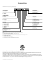
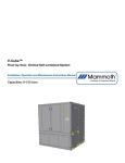
1
HRV Vertical Unit Ventilators
Classroom Ventilators with Energy Recovery
Installation, Operation and Maintenance Instructions Manual
Capacity: Up to 1,400 cfm
Model: HRV450w, HRV1000w
©2012 Venmar CES Inc.
Table of Contents
Nomenclature.......................................................................................................................................................................3
Safety Considerations..........................................................................................................................................................5
Specifications........................................................................................................................................................................5
Installation............................................................................................................................................................................6
Rough In.........................................................................................................................................................................6
Power..............................................................................................................................................................................6
Controls..........................................................................................................................................................................6
Airflow Balancing..........................................................................................................................................................7
System Operation.................................................................................................................................................................7
Sequence of Operation..................................................................................................................................................7
Ventilation......................................................................................................................................................................8
Heating...........................................................................................................................................................................8
High Temperature Limit Control...................................................................................................................................9
First Stage Cooling.........................................................................................................................................................9
Second Stage Cooling – Air Conditioning....................................................................................................................9
Recirculation Control...................................................................................................................................................10
Frost Control.................................................................................................................................................................10
Freeze Control Temperature Disc...............................................................................................................................10
System Service....................................................................................................................................................................10
Monthly Maintenance.................................................................................................................................................10
Annual Maintenance...................................................................................................................................................11
Appendix A: Unit Dimensions...........................................................................................................................................13
Appendix B: Ventilation and Airflow Information..........................................................................................................17
Appendix C: Electrical Data...............................................................................................................................................20
Appendix D: Low Voltage and High Voltage Wiring.......................................................................................................21
Appendix E: Thermostat and Wiring Connections...........................................................................................................22
Appendix F: Internal Thermostat......................................................................................................................................23
Manufacturer reserves the right to discontinue or change specifications or designs without notice or obligation.
VCES-VUV-IOM-1A – HRV450w & HRV1000w
2
Nomenclature
HRV450w Nomenclature (300–800 cfm)
1
2
3
4
5
6
7
8
9
10
11
1. FROST CONTROL
D – Recirc defrost1
N – Non-defrost
2. VOLTAGE
A – 120/1/602
B – 208/120/1/603
C – 230/120/1/603
3. ENERGY RECOVERY
P – Poly core
A – Aluminum core
4. HEATING
E – Electric heat
H – Hot water2
P – Proportional electric heat4
X – No heat2
5. HEATING CAPACITY
0 – No heat5
1 – 2.5 kW (one-stage)6
2 – 5.0 kW (one-stage)6
3 – 5.0 kW (two-stage)6
4 – 7.5 kW (two-stage)6
5 – 10.0 kW (two-stage)6
6 – 25,000 Btu7
7 – 50,000 Btu7
6. COOLING
D – Dx cooling
R – Fixed recirculation option
X – No cooling
12
12. BOTTOM BASE
B – Bottom base, no grille
G – Bottom base, c/w grille
X – No bottom base
11. EXTERNAL DISCONNECT
N – Non-fused disconnect switch8
X – No disconnect switch
10. EXHAUST AIR DAMPER
1 – Motorized
2 – Spring return
3 – No damper
9. OUTSIDE AIR DAMPER
1 – Insulated motorized
2 – Insulated spring return
3 – No damper
8. SUPPLY DISCHARGE
T – Top plenum, no grille
G – Top plenum, c/w grille
D – Top plenun, c/w double
deflection grille
X – No top plenum
7. CONTROLS
T – Thermostat
X – No thermostat
Notes:
1 When ordering recirc defrost, you must order outside air and exhaust air dampers.
2 Hot water and no heat options available in 120 VAC option only.
3 Requires a neutral wire with L1 and L2.
4 Must select a two-stage heating capacity option; first stage is proportional and second stage is fixed.
5 Only available with no heat.
6 Only available with electric heat.
7 Only available with hot water heating.
8 Non-fused disconnect switch is field installed (remote mounted).
©Venmar CES Inc. 2012. All rights reserved throughout the world.
Illustrations cover the general appearance of Venmar CES products at the time of publication and Venmar CES reserves the
right to make changes in design and construction at any time without notice.
CES Group, LLC d/b/a Venmar CES furnishes equipment pursuant to its then-current Terms and Conditions of Sale and Limited Warranty, copies of which can be found under the Terms & Conditions of Sale and Warranty link at www.ces-group.com.
Extended warranties, if any, shall be as offered and acknowledged in writing by Venmar CES.
VCES-VUV-IOM-1A – HRV450w & HRV1000w
3
HRV1000w Nomenclature (400–1,400 cfm)
1
2
3
4
5
6
7
8
9
10
11
1. FROST CONTROL
D – Recirc defrost1
N – Non-defrost
11. EXTERNAL DISCONNECT
N – Non-fused disconnect switch9
X – No disconnect switch
2. VOLTAGE
A – 120/1/602
B – 208/120/1/603
C – 230/120/1/603
10. EXHAUST AIR DAMPER
1 – Motorized
2 – Spring return
3 – No damper
9. OUTSIDE AIR DAMPER
1 – Insulated motorized
2 – Insulated spring return
3 – No damper
3. ENERGY RECOVERY
P – Poly core
A – Aluminum core
4. HEATING
E – Electric heat
H – Hot water
P – Proportional electric heat4
X – No heat
5. HEATING CAPACITY
0 – No heat5
1 – 2.5 kW (one-stage)6
2 – 5.0 kW (one-stage)6
3 – 5.0 kW (two-stage)6
4 – 7.5 kW (two-stage)6
5 – 10.0 kW (two-stage)6
6 – 12.5 kW (two-stage)6
7 – 15.0 kW (two-stage)6
8 – 50,000 Btu7
9 – 70,000 Btu7
6. COOLING
D – Dx cooling
X – No cooling
8. SUPPLY DISCHARGE
T – Top plenum, no grille
G – Top plenum, c/w grille
D – Top plenun, c/w double
deflection grille
S – Silencer plenum c/w double
deflection grille8
X – No top plenum
7. CONTROLS
T – Thermostat
X – No thermostat
Notes:
1 When ordering recirc defrost, you must order outside air and exhaust air dampers.
2 Hot water and no heat options available in 120 VAC option only.
3 Requires a neutral wire with L1 and L2.
4 Must select a two-stage heating capacity option; first stage is proportional and second stage is fixed.
5 Only available with no heat.
6 Only available with electric heat.
7 Only available with hot water heating.
8 Silencer plenum option is not available with Dx cooling option.
9 Non-fused disconnect switch is field installed (remote mounted).
VCES-VUV-IOM-1A – HRV450w & HRV1000w
4
Safety Considerations
Warning, Caution and Important notes appear throughout
this manual in specific and appropriate locations to alert
Installing Contractors, maintenance or service personnel of
potential safety hazards, possible equipment damage or to
alert personnel of special procedures or instructions that
must be followed as outlined below.
WARNING
!
Identifies an instruction which, if not followed, might cause
serious personal injuries including possibility of death.
CAUTION
Hazards may exist within this equipment because it contains electrical and powerful moving components. Only
qualified service personnel should install or service this
equipment. Untrained personnel can perform basic maintenance such as maintaining filters. Observe precautions
marked in literature and on labels attached to unit. Follow
all safety codes.
!
WARNING
Disconnect the main power switch to the unit before performing service or maintenance. Electric shock can cause
personal injury or death.
Identifies an instruction which, if not followed, might severely damage the unit, its components, the assembly or
final installation.
IMPORTANT
Indicates supplementary information needed to fully
complete an instruction or installation.
Specifications
The HRV Vertical Unit Ventilator series is one of the successful solutions to ventilation and indoor air quality problems from Venmar CES. This series consists of commercial
heat and energy recovery ventilators with heating and/or
cooling. Designed as appliances, they are ideally suited as
complete classroom ventilators. With an upright configuration and small footprint, they require a minimum amount
of space for installation. An optional top supply plenum allows for flexibility to suit various installations. The cabinet is
well insulated and tightly sealed to provide quiet operation.
Case
•
•
•
•
HRV450w – See Figure A1.
HRV1000w – See Figure A3.
Coil Dimension Drawings
•
•
HRV450w – See Figure A2.
HRV1000w – See Figure A4.
Supply and Exhaust Airflow
•
68% to 70% with heat recovery modules at rated
flow of 450 cfm.
Filtration (Supply and Exhaust)
•
•
HRV450w – 1” [25 mm] reticulated foam washable
filter 14” x 18” [356 x 457 mm] standard
HRV1000w – 2” [51 mm] MEF disposable filter 16” x
20” [406 x 508 mm] standard
Electric Heating Option
•
•
0.04” [1 mm] pre-finished steel
Heavy gauge pre-finished steel
Smooth texture
Bone white finish
Unit Dimensions
•
•
•
Open coil electric resistance elements
Two stage operation
–– Stage one: 2.5 kW to 5.0 kW 208/230V, onephase, 60 Hz
–– Stage two: 2.5 kW to 5.0 kW (HRV450w) 2.5 kW
to 10.0 kW (HRV1000w) 208/230V, one-phase,
60 Hz
Hydronic Heating Option
•
•
Aluminum hot water coil
Single stage operation
–– 25,000 Btu coil (7.3 kW) – HRV450w
–– 50,000 Btu coil (14.6 kW) – HRV450w,
HRV1000w
–– 70,000 Btu coil (20.5 kW) – HRV1000w
See Appendix B.
Heat Recovery Module
•
•
•
Polypropylene plate – standard.
Aluminum plate – optional.
Co-extruded tracks fit to allow for easy removal and
maintain low cross leakage.
VCES-VUV-IOM-1A – HRV450w & HRV1000w
5
Installation
Rough In
Drainage – Heat Exchanger/Cooling Coil
The wallmount ventilators must be installed on a level
base. Refer to Appendix A for dimensions. Zero clearance
is required between the bottom of the unit and any combustible material.
Units equipped with air conditioning have a condensate
line connected at the top of the unit which drains into the
main condensate line. The heat exchanger and cooling coil
drain must be fitted through the bottom of the case. Drain
connections within the case are accessible by removing the
bottom door. A length of PVC hose is supplied within the
case to make the drain connection.
Unit Installed without a Top Plenum
The supply air ducting must be connected to the supply
collar and constructed so there are no openings within
30” [762 mm] of the electric heating elements. Openings
within 30” [762 mm] of the elements must be fitted with
a permanent, non-removable protective screening. Zero
clearance is required between the supply duct and any
combustible material.
A water trap must be provided in the drain line to prevent
back flow of sewer gases. This trap may be achieved by
looping the drain line. The drain must be installed in an
area in which it will not freeze. If the wallmount ventilator
has a collector base, the drain hose will be located in the
base.
Power
!
Single-phase
WARNING
Ensure the power disconnect switch is off before connecting power to the unit or working with high voltage
lines.
A wiring diagram is supplied in Appendix D.
A sealed strain relief clamp (supplied by the installer) must
be fitted into the case to accommodate a power line
connection (see Appendix A for knock out location). If a
sealed clamp cannot be used, the hole must be sealed
with silicone or an equivalent water/air-tight sealant.
Power must be connected to the unit through a fused
disconnect switch (to be supplied by the Installer). If the
unit has a top supply plenum, a hole for the power must
be field drilled in the plenum to accommodate the main
power in.
L1
Hot
Black
L2
Hot
Red
N
Neutral
White
GND
Ground
Bare
L1
N
120 VAC 60 Hz
L2
L2
230 VAC 60 Hz or 208 VAC
Terminals for line connection are located in the control
box within the wallmount ventilator and are labeled as
shown below. Connections are illustrated in Appendix D.
Table 1: Line Connection to 208 VAC or 230 VAC, Singlephase, 60 Hz for Electric Heat
Table 2: Line Connection to 120 VAC 60 Hz Required for
Hydronic Heating
L1
Hot
Black
N
Neutral
White
GND
Ground
Bare
L1
N
120 VAC 60 Hz
Controls
External Switches
The wallmount ventilator controls (optional with Building Management System), are located on the left side
panel. These controls consist of two rocker switches. The
switches are labeled ‘Ventilation Rate’ and ‘First Stage
Heating’. The ‘Ventilation Rate’ switch sets the fan speeds
to ‘Low’, ‘Off’, or ‘High’. This switch is activated through
terminal G and is also a system switch for an internal thermostat. The ‘First Stage Heating’ switch engages or disengages the function of the internal thermostat. On versions
VCES-VUV-IOM-1A – HRV450w & HRV1000w
with hydronic heating, there will be no ‘First Stage Heating’ switch.
External Thermostat
Heating, cooling and ventilation can be controlled by a
remote thermostat. The wiring configuration for the thermostat subbase is shown in Appendix E. Ventilation may
otherwise be remote controlled by switching ‘R’ to ‘FL’ or
‘FH’. A separate information package on the subbase is
supplied with the wallmount ventilator.
6
The thermostat may be remote mounted on a nearby wall.
If it is remote mounted, control wire leads must be fitted
into the case through a sealed strain relief clamp where required. If a proper seal cannot be achieved with the clamp,
use silicone or an equivalent water/air-tight sealant.
Detailed control wiring is illustrated in Appendix D.
Internal Thermostat
Building Management System connections will vary by application. All control connections to the external thermostat are 24 VAC 60 Hz.
An internal thermostat will engage Stage One when the
supply air temperature falls below its setpoint. The function of this thermostat is disabled when the external heating switch is set to ‘Off’. The operation of this thermostat
is given in Appendix F. This thermostat is not available
with the hydronic heating option or Building Management
System option.
Table 3: Control Box Low Voltage Connections
Building Management Systems
Wire Color
Connection and Description
Black
R – 24 VAC Hot
White
Red
C – 24 VAC Common
W1 – Stage 1: Heating and signal for baseboard contactor (optional)
W2 – Stage 2: Heating and recirc
Yellow
Y1 – Stage 1: Free cooling
Control operation of the wallmount ventilator by a Building Management System is available by connecting to
the terminals described above. For full control of the
wallmount ventilator by the management system, external switches (if equipped) should be set to ‘Off’. External
switches set to ‘On’ will override the building management control. Each operation is activated by switching
terminal ‘R’ to the corresponding terminal.
Control Box Low Voltage Connections
Orange
Y2 – Stage 2: Dx Cooling (optional)
Violet
S1 – Occupied mode
S2 – N/A
C1 – N/A
FL – Fans low speed
Brown
FH – Fans high speed
Green
G – Fans auto (low)
Airflow Balancing
Once installed, the wallmount ventilator must operate
with balanced ventilation. Balanced ventilation is achieved
by obtaining equal rates of supply and exhaust airflow.
Airflow may be adjusted by balancing dampers (supplied
by Installer) within the supply and exhaust ductwork.
Systems that are not operating with balanced airflow will
not have effective energy recovery. Performance of the
heat recovery module will be reduced and freezing may
occur with cold outside air temperatures, resulting in
blockage of the heat recovery module.
System Operation
Sequence of Operation
Electric Models
•
The operating sequence is summarized by the following:
Signal from:
•
•
Internal Stat
–– Stage 1 heating
Signal to W1
–– Stage 2 heating
–– Fans to low speed
–– Send signal to baseboard contactors (optional in
field only)
VCES-VUV-IOM-1A – HRV450w & HRV1000w
•
•
Signal to W2
–– Supply fan on
–– Exhaust fan off
–– Stage 1 heating
–– Close ventilation damper
Signal to Y1
–– Supply fan to ‘High’ and exhaust fan ‘Off’ (free
cooling)
Signal to Y2
–– Air conditioning (optional)
–– Open recirc damper (HRV450w only)
7
–– Connection for condensing unit
Signal to S1
–– Engage occupied mode
• No signal to S1
–– Engage unoccupied mode (fans off) and close
vent damper. On a call for heat/cool the supply
fan runs only in recirculation mode (with frost
control option installed).
With the thermostat and sub-base, connect terminal G on
the sub-base to the terminal ‘G’ in the control box. This
will enable the ventilation to run on occupied cycles when
the ventilation rate switch is on either ‘High’ or ‘Low’ and
the T7350 fan operation shows ‘On’ in the lower right
area of the display screen. When the fan operation shows
‘Auto’ only, a call for heat or cool will engage fan operation. Press the ‘Fan’ button on the T7350 to alternate
between ‘On’ and ‘Auto’. See Appendix E for the wiring
details.
•
•
•
•
•
•
Signal to W2
–– Supply fan ‘High’
–– Exhaust fan ‘Off’
–– Close ventilation damper
Signal to Y1
–– Free cooling mode
–– Supply fan on ‘High’ and exhaust fan ‘Off’
Signal to Y2
–– Air conditioning
–– Connection for condensing unit
Signal to S1
–– Engage occupied mode
No signal to S1
–– Engage unoccupied mode (fans off) and close
vent damper (for units equipped with frost control). On a call for heat/cool the supply fan operates only.
Hydronic Models
The operating sequence is summarized by the following:
Signal from:
•
Signal to W1
–– Fans to low speed (duct stat to control zone
valve)
Ventilation
Fan speed can be selected by setting the external ventilation rate switch to ‘Low’, ‘Off’, or ‘High’. The fan operation on the T7350 must show ‘On’, in the lower right area
of the display screen, for continuous ventilation. If you do
not require ventilation, press the ‘Fan’ key to set the unit
to ‘Auto’. If ventilation is required, press the ‘Fan’ key to
set the unit to ‘On’. When the unit goes into the unoccupied mode, the ventilation will shut down even if the
display shows the ‘On’ operation.
Heating
Electric
An internal thermostat acts as a supply air temperature
monitor and engages heating as necessary to preheat supply air before delivering it to the space being ventilated.
This thermostat comes with all electric heat models.
This thermostat is not available with hydronic heating.
The thermostat contacts R and B make a closure on temperature fall which engages the heating contactor. The
thermostat is factory set at 59°F [15°C] (actual 55°F [13°C]
with differential set at two). For proper environment conditions, the temperature of the supply air diffused should
be no lower than 55°F. This thermostat can be deactivated
VCES-VUV-IOM-1A – HRV450w & HRV1000w
by turning the first stage heating switch to the ‘Off’ position. Further instructions for setting the thermostat are
given in Appendix F.
If no heating is required at all, then the first stage heating switch should be in the ‘Off’ position and the T7350
should display either ‘Off’ or ‘Cool’. During cooling season, the first stage heating switch should be in the ‘Off’
position.
Hydronic
Units equipped with hot water heating coils will come
without controls for controlling flow, etc. Hot water piping connections are shown in Appendix A, Figure A2 and
8
Figure A4. Control valve is to be hooked up to a remote
duct stat supplied by others (optional connection to ‘W1’
on the sub-base). All wiring is low voltage. This operation
is single-stage and on a second stage call for heat the sup-
ply fan will go to high speed, the exhaust fan will shut off,
and the unit will go into recirc mode. See Appendix A, Figure A2 and Figure A4 for more details.
High Temperature Limit Control
IMPORTANT
Electric models only.
Temperature limit thermostats in the heating circuit will
break contact to the heating elements when the temperature rise across the heating elements becomes excessive.
This may be due to blocked filters, blocked energy recovery module, blocked ducting, fan failure or fan relay failure. See the System Service section for proper equipment
maintenance.
First Stage Cooling
First stage cooling puts the supply fan to high speed and
the exhaust fan shuts off.
Second Stage Cooling – Air Conditioning
Second stage cooling is an option and will call for Dx cooling from a remote condensing unit. Both fans will run on
high speed.
Air conditioning is provided as an option. A field connection from ‘Y2’ on the terminal block (inside control box)
must be run to the contactor in the remote condensing
unit. This line will be 24 VAC hot. If a return line is also
required for the contactor, it can be taken from terminal
‘C’. See wiring diagram in control box for further details.
Suction and liquid line connections are made at the coil
(equipped with solder connects).
Air Conditioning Coil Installation
Place the provided insulation on top of the unit over the
matching supply opening. Place the coil and drain pan assembly over the insulation and supply air opening. Place
clips in opposing corners of coil drain pan and fasten
down to the top of unit with screws. Leave enough clearance around the back and side edges of the unit to allow
installation of the top supply discharge plenum or ducting
as required.
See Appendix A, Figure A2 and Figure A4 for installing the
air conditioning coil on top of the wallmount ventilator.
Holes in the top supply plenum are to be field drilled to
accommodate the refrigerant lines. On a call for cooling,
both fans will go to high speed and the recirc damper on
the right side of the unit will open to allow for increased
airflow over the coil.
!
WARNING
To prevent poor performance for air conditioning allow
4” to 6” [102 to 152 mm] from the right side to any wall
or partition.
VCES-VUV-IOM-1A – HRV450w & HRV1000w
9
Recirculation Control
In the HRV450w ventilation mode, the ventilation damper
is open and the supply air is 100% outdoor air. In the
HRV1000w ventilation mode, the ventilation damper is
open and the supply air is a mixture with a percentage of
return air (see Table B2 or Table B3).
plenum. Units equipped with recirculation control are built
with a damper mechanism controlling airflow through the
intake duct. Ventilation mode is activated by a signal to
terminal S1. Recirculation mode is activated when there is
a signal from W2 or when there is no signal to S1.
In recirculation mode, the ventilation damper is closed,
100% of the supply air is recirculated air from the return
Frost Control
Units with frost control are equipped with recirculation
control. Frost control consists of a timer/controller which is
activated by a thermostat which monitors the outside air
temperature passing through the air intake.
When the HRV450w and HRV1000w are in ventilation
mode at temperatures below 23°F [−5°C], the frost control
timer/controller activates recirculation control periodically
to keep the flat plate heat exchanger free from frost.
Freeze Control Temperature Disc
A bi-metallic disc (field installed) is provided with hydronic
units to prevent the coils from freezing up. This disc is
located near the supply fan and is to be connected to the
zone valve that controls the flow to the coil. When the
temperature in the cabinet goes below freezing, the disc
closes its contacts to engage the flow through the coil to
prevent the coil from freezing. See the wiring diagram on
unit control box cover for more details.
System Service
Monthly Maintenance
!
WARNING
Disconnect power before maintaining the unit.
Air Filters
HRV450w
The washable black foam filters should be cleaned
monthly or as required by operating conditions. The optional medium efficiency filters are disposable and should
be replaced monthly or as required by operating conditions. To remove the filters, simply remove the top access
door and slide the filter out of the guide (see Figure 1).
When installing a new filter, the airflow arrow should
point in the direction of the heat exchanger.
Figure 1: HRV450w exhaust filter
HRV1000w
The standard medium efficiency filters are disposable and
should be replaced monthly or as required by operating
conditions. When installing a new filter, the airflow arrow
should point in the direction of the heat exchanger.
To remove the HRV1000w filters, simply remove the bottom access door and slide the filter out of the guide.
VCES-VUV-IOM-1A – HRV450w & HRV1000w
10
!
WARNING
Disconnect power before maintaining the unit.
Figure 3: HRV1000w exhaust filter
Figure 2: HRV1000w exhaust filter
Annual Maintenance
Drain Pans and Interior of Unit
The inside of the unit, including drain pans (if equipped),
should be wiped clean annually with a soft cloth and mild
cleaning solution. Check the drain fittings (if equipped) to
ensure they are draining freely.
Plate Heat Exchanger
Clean the heat recovery module by removing it from the
unit and washing out the spaces between the plates using
a mild detergent. If a high pressure hose is used, avoid
causing damage to the exchanger by making sure that the
nozzle does not get too close to it.
To remove the supply blower, first remove the two screws
holding the blower in place, disconnect the electrical plug
and slide the blower out of the unit.
To remove the exhaust blower, the control box has to be
removed. Disconnect the electrical plugs from the control
box and remove the four screws holding it in place to
expose the exhaust blower. Remove the two wing screws
and slide the exhaust blower out.
Heaters/Air Conditioning Coils
Check the duct heaters, hot water coils and air conditioning coils for obstruction or build-up of dust. Check the
manual reset button on your duct heaters (if unit has electric heat). If the red buttons are released out, depress the
red button to reset the switch. If this problem persists, call
your local technician.
Dampers
Check inside dampers for obstruction and cleanliness.
Fans
Blower wheels and fan housings should be checked for
dust build-up. If excessive dust build-up exists, it will be
necessary to remove the blower assembly to clean the dust
out through the fan mouth.
VCES-VUV-IOM-1A – HRV450w & HRV1000w
Figure 4: Remove wing screws on supply blower
11
!
WARNING
Disconnect power before maintaining the unit.
Figure 6: Remove supply blower
Figure 5: Disconnect electrical plugs
VCES-VUV-IOM-1A – HRV450w & HRV1000w
12
VCES-VUV-IOM-1A – HRV450w & HRV1000w
Outdoor air
Exhausr air
Return air
94.00”
[2388]
Supply air
LEFT VIEW
Return Collector
Base (optional)
Top supply
plenum
(optional)
20.50”
[521]
5.00”
[127]
Filter
Return air
A 2” [51] space
must be left
between the right
side of the unit
and any obstruction
to allow airflow.
Recirculation
opening for units
with cooling.
Supply air
24.00” x 6.00” [610 x 153]
Double deflection grille
8.00”
[203]
24.00” x 6.00” [610 x 153]
Fixed grille @ 45º
FRONT VIEW
Control
box
32.00”
[813]
3.50”
[89]
Supply air
opening
16.00”
[406]
TOP VIEW WITH
DUCTED SUPPLY PLENUM
5.60”
[142]
65.00”
[1651]
8.50”
[216]
31.00”
[787]
Outdoor air
5.00”
[127]
20.50”
[521]
Outdoor air
intake opening
14.00” x 8.00”
[356 x 203]
3.25” [83]
Outdoor air
duct opening
18.00” x 20.00”
[457 x 508]
Exhaust fan
mouth opening
9.00” x 6.00”
[229 x 152]
Exhaust air
duct opening
14.00” x 14.00”
[356 x 356]
8.00”
[203]
4. Maintenance: Allow minimum
24” [610] clearance for front access.
Exhaust air
RIGHT VIEW
Return Collector
Base (optional)
10.60”
[269]
Top supply
plenum
(optional)
Direction of airflow
3. Factory supplied outdoor air louvers
require wall penetrations as shown
for air duct opening sizes.
2.
Notes:
1. Dimensions in [ ] are millimeters.
2.50”
[64]
BACK VIEW
Supply air
2.25”
[57]
1.75”
[44]
2.50”
[64]
4.00”
[102]
2.00”
[51]
Appendix A: Unit Dimensions
Figure A1: HRV450w unit dimensions
13
Figure A2: HRV450w coil dimensions
VCES-VUV-IOM-1A – HRV450w & HRV1000w
14
65.00”
[1,651]
3.50”
[89]
4.50”
[114]
11.00”
[279]
11.00”
[279]
Supply
air
opening
FRONT VIEW
C
1.63”
[41]
Note:
Dimensions in [ ] are millimeters.
2.25”
[57]
A
12.00”
[305]
B
2.88”
[73]
2.50”
[64]
2.81”
[71]
2.38”
[60]
3.13”
[80]
13.00”
[330]
TOP VIEW WITHOUT
SUPPLY PLENUM
Connection Table
Connection sizes
A Field power supply outlet
1 1/8”
B Coil connection
7/8” (sweat)
C Coil connection
7/8” (sweat)
25/50 MBTU HYDRONIC
65.00”
[1,651]
3.50”
[89]
4.50”
[114]
A
FRONT VIEW
Supply
air
opening
10.00”
[254]
8.00”
[203]
3.25”
[83]
9.00”
[229]
TOP VIEW WITHOUT
SUPPLY PLENUM
Connection Table
Connection Sizes
A Field power supply outlet
1 1/8”
ELECTRIC HEAT
C
FRONT VIEW
Supply
air
opening
19.50”
[495]
12.00”
[305]
8.00” 14.25”
[203] [362]
10.00”
[254]
Note:
Drain for condensate for cooling coil will have to be installed out the
bottom of the unit.
B
4.50”
[114]
3.50”
[89]
65.00”
[1,651]
A
C
B
TOP VIEW WITHOUT
SUPPLY PLENUM
Connection Table
Connection Sizes
A Field power supply outlet
1 1/8”
B Supply
3/8” (sweat)
C Suction
3/4” (sweat)
DX COOLING
Figure A3: HRV1000w unit dimensions
VCES-VUV-IOM-1A – HRV450w & HRV1000w
15
Outdoor air
Exhaust air
LEFT VIEW
21.00”
[533]
Return air
92.50”
[2350]
Supply air
Filter
Control
box
8.00”
[203]
FRONT VIEW
41.00”
[1,041]
6.00”
[152]
Supply air
opening
20.00”
[508]
Fixed grille @ 45º
RIGHT VIEW
36.00” x 6.00” [914 x 153]
Return air
Supply air
Double deflection grille
24.00” x 6.00” [610 x 153]
7.00”
[178]
3.00”
[76] 3.50”
[89]
2.00”
[51]
TOP VIEW WITH
DUCTED SUPPLY PLENUM
8.50”
[216]
Outdoor air
68.00”
[1,727]
Exhaust air
Outdoor air
intake opening
14.00” x 8.00”
[356 x 203]
3.25” [83]
Outdoor air
duct opening
18.00” x 20.00”
[457 x 508]
Exhaust fan
mouth opening
9.00” x 6.00”
[229 x 152]
Exhaust air
duct opening
14.00” x 14.00”
[356 x 356]
8.00”
[203]
2.50”
[64]
BACK VIEW
Supply air
1. Dimensions in [ ] are millimeters.
2.
Direction of airflow
3. Factory supplied outdoor air louvers
require wall penetrations as shown
for air duct opening sizes.
4. Maintenance: Allow minimum
24” [610] clearance for front access.
Notes:
2.25”
[57]
1.75”
[44]
2.50”
[64]
4.00”
[102]
2.00”
[51]
Figure A4: HRV1000w coil dimensions
VCES-VUV-IOM-1A – HRV450w & HRV1000w
16
1.00”
[25]
3.38”
[86]
B
20.00”
[508]
4.50”
[114]
A
1.75”
[44]
68.00”
[1,727]
Outdoor air
Exhaust air
2.25”
[57]
C
RIGHT VIEW
16.63”
[422]
18.50”
[470]
1.19”
[30]
Supply air
opening
3.00”
[76]
TOP VIEW
WITHOUT SUPPLY PLENUM
Note:
Dimensions in [ ] are millimeters.
C
B
A
Connection Table
Connection Sizes
Field power supply outlet
1¼”
Coil connection
½” (sweat)
Coil connection
½” (sweat)
HYDRONIC HEAT
4.50”
[114]
68.00”
[1,727]
A
3.00”
[76]
FRONT VIEW
9.50”
[241]
Supply air
opening
8.00”
[203]
11.50”
[292]
TOP VIEW
WITHOUT SUPPLY PLENUM
Connection Table
Connection Sizes
A Field power supply outlet
1¼”
ELECTRIC HEAT
7.00”
[178]
68.00”
[1,727]
11.50”16.00”
[292] [406]
9.50”
[241]
14.00”
[356]
FRONT VIEW
A
Supply air
opening
18.00”
[457]
Note:
Drain for condensate for cooling coil will have to be installed
out the bottom of the unit.
B
C
4.50”
[114]
3.00”
[76]
B
C
TOP VIEW
WITHOUT SUPPLY PLENUM
Connection Table
Connection Sizes
A Field power supply outlet
1¼”
B Supply
3/8” (sweat)
C Suction
3/4” (sweat)
DX COOLING
Appendix B: Ventilation and Airflow Information
Table B1: HRV450w Ventilation
ESP (in. w.g.)
0.00
Polypropylene
Core Low Speed
460
Polypropylene
Core High Speed
685
Aluminum Core
Low Speed
460
Aluminum Core
High Speed
710
Recirc. Open for
Dx Cooling
800
0.10
435
630
445
665
750
0.15
415
600
435
640
725
0.20
400
580
425
605
705
0.25
380
550
410
585
675
0.30
365
510
390
555
645
0.35
340
480
375
540
605
0.40
305
435
355
495
570
0.45
280
410
335
460
530
0.50
250
375
295
430
495
0.55
220
335
265
395
460
0.60
190
N/A
235
340
415
External static pressure is calculated by totalling the individual air pressure drops for the following options: electric heat, hot water heat, evaporator
cooling coil, top supply plenum and louvers.
Table B2: HRV1000w Reduced Low Speed Airflow Information
Position of Recirc Panel
Fully
Closed
TA
(CFM)
920
TA
(CFM)
1,150
OA
(CFM)
890
TA
(CFM)
1,270
OA
(CFM)
860
TA
(CFM)
1,360
OA
(CFM)
855
TA
(CFM)
1,400
OA
(CFM)
685
TA
(CFM)
1,430
OA
(CFM)
650
0.10
885
1,095
870
1,215
830
1,300
815
1,345
665
1,360
635
0.20
830
1,050
835
1,160
810
1,245
795
1,270
645
1,300
625
Supply
ESP
Fan
(in. w.g.)
0.00
Speed 1
Speed 2
1
2
3
4
Fully Open
0.30
790
985
805
1,120
780
1,190
755
1,205
625
1,245
610
0.40
725
935
770
1,060
750
1,135
735
1,150
615
1,180
590
0.50
685
885
740
995
710
1,075
710
1,080
595
1,095
575
0.60
610
810
690
945
675
1,015
665
1,000
575
1,020
550
0.70
545
745
640
855
635
915
635
900
545
920
520
0.80
455
670
600
775
600
820
590
790
505
810
485
0.90
—
545
540
645
540
715
540
660
465
675
450
1.00
—
—
—
—
—
555
475
490
415
490
390
0.00
870
1,020
810
—
—
—
—
—
—
—
—
0.10
835
970
785
1,075
745
1,090
705
1,095
570
1,110
565
0.20
775
935
765
1,025
730
1,060
690
1,065
565
1,065
555
0.30
735
885
735
980
700
1,030
675
1,020
550
1,035
550
0.40
685
845
710
930
670
980
655
970
540
970
535
0.50
625
805
685
895
650
930
630
920
530
940
530
0.60
575
735
640
845
625
880
610
860
510
900
515
0.70
505
670
600
765
595
815
580
785
485
830
490
0.80
405
585
555
680
555
725
545
670
445
730
450
0.90
—
—
—
550
490
605
490
545
405
600
420
Additional internal static pressure due to accessories must be known to determine ESP.
This data includes factory selected louver and electric heat coils.
OA balancing damper may be required to achieve desired ventilation air volume.
Exhaust fan is set to low speed for shaded cells.
VCES-VUV-IOM-1A – HRV450w & HRV1000w
17
Table B2: HRV1000w Reduced Low Speed Airflow Information
Position of Recirc Panel
Supply
ESP
Fan
(in. w.g.)
0.00
0.10
Speed 3
Speed 4
Fully
Closed
TA
(CFM)
—
TA
(CFM)
—
OA
(CFM)
—
TA
(CFM)
—
OA
(CFM)
—
TA
(CFM)
—
OA
(CFM)
—
TA
(CFM)
—
OA
(CFM)
—
TA
(CFM)
—
OA
(CFM)
—
765
815
680
—
—
—
—
—
—
—
—
1
2
3
4
Fully Open
0.20
715
795
670
845
615
865
595
860
495
865
485
0.30
660
765
650
835
610
845
585
815
490
845
475
0.40
610
735
630
785
600
805
570
795
485
810
470
0.50
575
705
615
765
585
785
565
745
465
780
465
0.60
520
650
595
710
550
735
535
695
450
730
450
0.70
420
585
555
655
540
670
510
625
430
660
435
0.80
365
505
510
565
495
580
475
545
415
560
405
0.90
—
—
—
—
—
460
420
385
355
455
375
0.00
—
—
—
—
—
—
—
—
—
—
—
0.10
650
—
—
—
—
—
—
—
—
—
—
0.20
610
—
—
—
—
—
—
—
—
—
—
0.30
575
635
570
665
530
670
510
660
435
650
420
0.40
540
610
565
655
520
655
505
635
430
640
415
0.50
485
585
555
630
515
620
490
610
420
615
415
0.60
430
545
530
580
505
595
475
585
415
575
405
0.70
365
490
490
525
470
540
455
520
395
505
390
0.80
—
—
—
405
415
460
420
420
365
405
365
Additional internal static pressure due to accessories must be known to determine ESP.
This data includes factory selected louver and electric heat coils.
OA balancing damper may be required to achieve desired ventilation air volume.
Exhaust fan is set to low speed for shaded cells.
Table B3: HRV1000w High Speed and Regular Low Speed Airflow Information
Position of Recirc Panel
Supply
ESP
Fan
(in. w.g.)
0.00
0.10
Speed 1
Fully
Closed
TA
(CFM)
1,000
TA
(CFM)
1,230
OA
(CFM)
875
TA
(CFM)
1,355
OA
(CFM)
855
TA
(CFM)
1,470
OA
(CFM)
825
TA
(CFM)
1,560
OA
(CFM)
805
TA
(CFM)
1,605
OA
(CFM)
790
950
1,180
835
1,305
835
1,415
795
1,510
785
1,540
770
1
2
3
4
Fully Open
0.20
895
1,105
815
1,240
805
1,355
775
1,445
760
1,465
740
0.30
840
1,045
795
1,190
770
1,295
750
1,360
725
1,395
710
0.40
780
980
755
1,135
740
1,215
710
1,290
700
1,315
680
0.50
715
915
710
1,060
710
1,145
690
1,225
680
1,235
655
0.60
645
840
665
995
675
1,075
655
1,140
640
1,170
635
0.70
565
745
620
910
635
980
620
1,055
610
1,070
600
0.80
445
660
565
805
590
875
575
940
580
975
570
0.90
—
—
—
680
535
765
540
780
515
835
520
1.00
—
—
—
—
—
—
—
—
—
—
—
Additional internal static pressure due to accessories must be known to determine ESP.
This data includes factory selected louver and electric heat coils.
OA balancing damper may be required to achieve desired ventilation air volume.
Exhaust fan is set to low speed for shaded cells.
VCES-VUV-IOM-1A – HRV450w & HRV1000w
18
Table B3: HRV1000w High Speed and Regular Low Speed Airflow Information
Position of Recirc Panel
Supply
ESP
Fan
(in. w.g.)
0.00
0.10
Speed 2
Speed 3
Speed 4
Fully
Closed
TA
(CFM)
1,000
TA
(CFM)
1,190
OA
(CFM)
855
TA
(CFM)
1,305
OA
(CFM)
820
TA
(CFM)
1,390
OA
(CFM)
790
TA
(CFM)
1,455
OA
(CFM)
760
TA
(CFM)
1,500
OA
(CFM)
745
940
1,135
815
1,255
795
1,330
770
1,410
740
1,445
720
1
2
3
4
Fully Open
0.20
880
1,090
805
1,190
770
1,270
740
1,350
420
1,375
705
0.30
815
1,030
770
1,135
745
1,215
715
1,290
700
1,300
680
0.40
755
965
740
1,075
710
1,145
685
1,210
660
1,235
655
0.50
680
895
690
1,010
680
1,090
665
1,130
640
1,170
635
0.60
620
825
645
945
645
1,010
640
1,070
610
1,085
610
0.70
525
735
600
850
600
925
595
960
575
990
575
0.80
—
630
545
765
575
835
565
865
550
885
550
0.90
—
—
—
630
510
700
510
710
490
740
495
0.00
960
1,120
820
1,200
775
1,280
745
1,300
695
1,325
675
0.10
910
1,075
795
1,145
745
1,230
715
1,250
670
1,290
660
0.20
845
1,030
770
1,105
720
1,175
700
1,210
655
1,235
650
0.30
785
965
730
1,060
705
1,130
670
1,155
640
1,185
640
0.40
725
915
700
995
670
1,075
650
1,100
620
1,130
625
0.50
670
840
670
945
635
995
615
1,040
600
1,055
595
0.60
595
775
625
875
605
925
595
960
575
990
575
0.70
495
690
575
785
580
850
555
865
550
895
550
0.80
390
580
505
680
540
745
520
780
515
800
515
0.90
—
—
—
—
—
605
465
640
470
740
450
0.00
910
1,025
745
1,075
690
1,090
655
1,070
620
—
—
0.10
865
985
730
1,010
670
1,075
640
1,055
610
1,070
595
0.20
805
935
700
980
655
1,040
625
1,005
600
1,055
590
0.30
745
880
675
945
640
1,025
615
960
580
1,025
580
0.40
680
825
645
850
595
960
600
905
555
975
565
0.50
620
765
610
805
585
910
575
855
540
925
550
0.60
550
705
590
775
575
840
550
780
515
865
540
0.70
440
620
490
700
540
765
530
675
475
790
515
0.80
—
—
—
605
410
655
475
—
—
685
470
Additional internal static pressure due to accessories must be known to determine ESP.
This data includes factory selected louver and electric heat coils.
OA balancing damper may be required to achieve desired ventilation air volume.
Exhaust fan is set to low speed for shaded cells.
VCES-VUV-IOM-1A – HRV450w & HRV1000w
19
Appendix C: Electrical Data
Table C1: 208 VAC HRV450w Electric Heat
AC Option
Amount of
Heat
MCA
2.5 kW
5.0 kW
7.5 kW
10.0 kW
20.6
35.6
50.8
65.8
MOP
BTU/hr
25
40
60
70
1½ Ton
kW
5.3
5.3
5.3
5.3
8,533
17,065
25,598
34,130
2 Ton
BTU/hr
18,000
18,000
18,000
18,000
kW
7.0
7.0
7.0
7.0
BTU/hr
24,000
24,000
24,000
24,000
Table C2: 230 VAC HRV450w Electric Heat
AC Option
Amount of
Heat
MCA
2.5 kW
5.0 kW
7.5 kW
10.0 kW
19.3
32.8
46.4
60.0
MOP
BTU/hr
20
35
50
60
1½ Ton
kW
5.3
5.3
5.3
5.3
8,533
17,065
25,598
34,130
2 Ton
BTU/hr
18,000
18,000
18,000
18,000
kW
7.0
7.0
7.0
7.0
BTU/hr
24,000
24,000
24,000
24,000
Table C3: 120 VAC HRV450w Hydronic Heat
Amount of Heat
No heat
25 MBH H2O coil
50 MBH H2O coil
MCA
MOP
kW
BTU/hr
5.6
5.6
5.6
9
9
9
0.0
6.7
10.8
0
23,000
37,000
kW
5.3
5.3
5.3
AC Option
1½ Ton
2 Ton
BTU/hr
kW
BTU/hr
18,000
7.0
24,000
18,000
7.0
24,000
18,000
7.0
24,000
Table C4: 208 VAC HRV1000w Electric Heat
Amount of Heat
2.5 kW
5.0 kW
7.5 kW
10.0 kW
12.5 kW
15.0 kW
MCA
MOP
BTU/hr
22.8
37.8
52.9
67.9
82.9
97.9
25
40
60
70
90
100
8,533
17,065
25,598
34,130
42,663
51,195
MCA
MOP
BTU/hr
21.4
34.9
48.5
62.1
75.6
89.3
25
35
50
70
80
90
8,533
17,065
25,598
34,130
42,663
51,195
AC Option – 3 Ton
kW
BTU/hr
10.5
36,000
10.5
36,000
10.5
36,000
10.5
36,000
10.5
36,000
10.5
36,000
Table C5: 230 VAC HRV1000w Electric Heat
Amount of Heat
2.5 kW
5.0 kW
7.5 kW
10.0 kW
12.5 kW
15.0 kW
AC Option – 3 Ton
kW
BTU/hr
10.5
36,000
10.5
36,000
10.5
36,000
10.5
36,000
10.5
36,000
10.5
36,000
Table C6: 120 VAC HRV1000w Hydronic Heat
Amount of Heat
MCA
MOP
kW
BTU/hr
No heat
50 MBH H2O coil
70 MBH H2O coil
12.1
12.1
12.1
15
15
15
0.0
14.6
20.5
0
50,000
70,000
VCES-VUV-IOM-1A – HRV450w & HRV1000w
AC Option – 3 Ton
kW
BTU/hr
5.3
18,000
5.3
18,000
5.3
18,000
20
Appendix D: Low Voltage and High Voltage Wiring
FACTORY
WIRING
CONTROL BOX
TERMINAL BLOCK
FACTORY
WIRING
BLACK
R
BLACK
WHITE
C
WHITE
ORANGE
W1
ORANGE
RED
W2
VIOLET
YELLOW
Y1
GREY
Y2
YELLOW
S1
BLUE
VIOLET
S2
C1
FL
ORANGE
BROWN
FH
RED
GREEN
G
Figure D1: Connections to terminal block in control box
N
Ground
L2
L1
L1
L2
N
High voltage terminals
Notes:
1. Fused disconnect switch supplied by Installer.
2. 208–230 VAC/120/1/60 requires a neutral wire
to be run with L1 and L2.
3. For 120/1/60 volt units, L2 is not required.
Figure D2: Single-phase power supply wiring
VCES-VUV-IOM-1A – HRV450w & HRV1000w
21
Appendix E: Thermostat and Wiring Connections
Thermostat Sub-base Setup
Thermostat Setup
Factory supplied thermostats and sub-bases are configured
and ready for installation. Use this information to configure thermostats that are field supplied.
See the manufacturer’s instruction manual for detailed
instructions on how to program the following thermostat
functions that must be set:
1.
2.
3.
4.
5.
Install jumper wires across the following terminals; refer to
Figure E1.
Jumper Connections – Sub-base
•
•
1 – ‘RH’ to ‘RC’ (factory installed)
Connections ‘R’, ‘C’ , ’W’, etc. to ventilation unit are
as shown.
Day of the week
Time
Daily schedules
System (heat, cool, automatic)
Fan (on, auto)
TB2003
R
WIRE TO UNIT TERMINAL STRIP
C
W1
T5 T6 T7 T4 T3 Os Os As As
R
ws/y4
W2
Y3 W2 Y2
Y2
W2
Factory
installed
jumper
C
G
Hs Hc Hp M
M
X
Rh Rc aux W1 Y1
G
Y1
W1
Y1
S1
Y2
S1
S2
C1
FL
FH
G
UNIT TERMINAL STRIP
Figure E1: Thermostat sub-base setup
VCES-VUV-IOM-1A – HRV450w & HRV1000w
22
Appendix F: Internal Thermostat
T675A
Terminal screws (3)
As the temperature of the controlled medium falls below
the setpoint less differential, the T675A switch makes
terminals R to B and energizes a normally closed solenoid
valve to provide heat. In cooling applications, the T675A
makes terminals R to W as the temperature rises above the
set point, energizing cooling equipment. Figure F1 shows
the operation of the T675A. Figure F2 shows the location
of the adjustment dial on models with an adjustable differential.
V-notch
Freeze-up Protection
When using the T675A (auto recycling) for freeze-up protection, the recommended setpoint is 38°F [3.3°C] plus
the switch differential.
Example
Setpoint of 38°F [3.3°C] plus 1°F [0.6°C] (fixed differential
model) equals an actual setpoint of 39°F [3.9°C].
1415B
T675A differential
adjustment dial
Figure F2: Adjustment dial location on T675A models with
an adjustable differential
Example
Setpoint of 38°F [3.3°C] plus 3°F [1.7°C] (adjustable differential model) equals an actual setpoint of 41°F [5°C].
This provides an adequate safety factor for freeze-up protection.
Setpoint
(adjustable)
Temperature rise
R-W makes
R-B breaks
on rise
1
Switch differential
(adjustable from approximately
3°F to 10°F [1.7°C to 5.6°C]
on standard models, or from 3.6°F
to 12°F [2.0°C to 6.7°C] on 55°F
to 175°F [13°C to 79°C] models)
R-W breaks
R-B makes
on fall
1
Models also available with a fixed differential
of approximately 1°F [0.6°C].
1416A
Figure F1: T675A operation
VCES-VUV-IOM-1A – HRV450w & HRV1000w
23
[email protected]
www.venmarces.com
Venmar CES Inc. has a policy of continuous improvement and reserves
the right to change design and specifications without notice.
©2012 Venmar CES Inc.
VCES-VUV-IOM-1A (PN 207410)
February 2014