1
OWNERS
MANUAL
MODEL NO.
917.254661
Caution:
Read and Follow
All Safety Rules
And instructions
Before Operating
This Equipment
L T 12 HP ELECTRIC
START
6 SPEED o 38" MOWER
L A WN TRA C TOR
® Assembly
® Operation
o Maintenance
• Repair
® Repair
.........
Sears,
i
Roebuck
i,
i
and
i
i
Co.,
and Adjustment
Parts
ii i ,i ii,ll,,i
i,, ,ll
Chicago,
i
ii
IL 60684
U S.A.
i,i
i,l,,,
inlll
illll
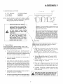
LOOK
FOR
THIS
SYMBOL
TO POINT
CAUTION:
TIONS.
IT MEANS - ATTENTION!
BEOUT
IMPORTANT
SAFETY
PRECAUCOME
ALERT!
YOUR SAFETY
IS INVOLVED.
LOOK FOR THIS WORD TO POINT OUT
IMPORTANT EQUIPMENT PRECAUTIONS,,
RULES FOR SAFE OPERATION
c.
d.
Do not turn sharply. Use care when backing.
Use counterweight or wheelweights when suggested in
owner's manuals.
__4,Watch out for traffic when crossing or near roadways.
_.5_"_Whenusing any attachments, never direct discharge of
_0aterial toward bystanders nor allow anyone near the vehicle while in operation..
26. Hiandle gasoline with care - it is highly flammable.
1_
Know the controls and how to stop quickly. READ THIS
OPERATOR'S
MANUAL and instructions furnished with
attachments,
2_ Do not allow children to operate the machine. Do not allow/
adults to operate it without proper instruction,
./"
3._ Do not carry passengers_ Do not mow when childreqiand
others are around.
,/
4. Always wear substantial footwear. Do not wear Ioos_ fitting
clothing that could get caught in moving parts.
5. Keep your eyes and mind on your tractor, mower/and the
area being cut.. Do not let other interests distract YibUo .
6. Do not attempt to operate your tractor or mower wi_en not in
the drivers seat.,
7o Always get on or off your tractor from the operator's_,left hand
side,
'\ "
8. Clear the work area of objects (wire, rocks, etc_) which might
be picked up and thrown..
9. Disengage allattachment clutches before attempting t_start
the engine.
I 0.. Disengage powerto attachments and stop the engine befo'_
leaving the operator's position..
"
1t Disengage power to mower, stopthe engine, and disconnect
spark plug wire(s) from spark plug(s) before cleaning, making
an adjustment, or repair, Be careful to avoid touching hot!
muffler or' engine components..
/
12. Disengage power to attachments when transporting or no/t4n
use,
Never remove the fuel cap of the fuel tank or add
gasoline
to a run'ningor
hot engine or an engine that has
se been
approved
gasoline
not
allowed
to coolcontainers.
for several minutes after running., Never fill tank indoors, always clean up spilled
gasoline
c. Open doors if the engine is run in the garage - exhaust
fumes are dangerou& Do not run the engine indoors.
_7,. Keep the vehicle and attachments in good operating condition, and keep safety devices in place and working_
2& Keep all nuts, bolts, and screws tight to be sure the equipment is in safe working condition.
29.. Never store the equipment with gasoline in the tank inside a
building where fumes may reach an open flame or spark
Mow the engine to cool before storing in any enctosur&
30. To reduce fire hazard keepthe engine free of arass, leaves,
",Nor excessive grease,. Do not clean product wT_ile engine is
\running.
31_ 'Except for adjustments, DO NOT operate Engine if air
cl'e.aner or cover directly over carburetor air intake is remo'_ed, Removal of such part cou[d create a fire hazard..
32_Do fkot operate without a muffler, or tamper with exhaust
syste_ Damaged mufflers or spark attesters could create a
fii'e hair&
inspect periodically and replace if necessary.
33. The vel_cle and attachments should be stopped and inspected f&,r damage after striking a foreign object, and the
damage sh'_,uld be repaired before restarting and operating
the equipme_.
34. Do not change'the engine governor settings or overspeed the
engine; severe damage or injury may result.
35.. When using the vehicle with mower, proceed as follows:
a,, Mow only in daylight or in good artificial light,
b, Shut the Engine off when unclogging chute°
c,, Check the blade mounting bolts for proper tightness at
frequent intervals1,
36. Do not operate the mower without either the entire grass
catcher, on mowers so equipped, or the deflector shield in
place,.
37,, Disengage power to mower before backing up_ Do not mow
in reverse unless absolutely necessary and then only after
careful observation of the entire area behind the mower.
3& Under normal usage the grass catcher bag material is subject
to deterioration and wear. Itshould be checked frequently for
bag replacement Replacement bags should be checked to
ensure compliance with the original manufacturer's recommendations or specifications_
i
t
t3.. Take all possible precautions when leaving the v_(hicle
unattended, Disengage the power-take-off, lower the,zittaci!ments, return drive control lever to neutral,(shift into4eutral),
set the parking brake, stop the engine, and remov/_ the key..
t4,. Do not stop or start suddenly when going uphill_fr downhill.
Mow up and down the face of slopes (not great/ar than 15°);
never across the face.
,/
15_ Reduce speed on slopes and make turns gradually to prevent
tipping or loss of control. Exercise extrgfne caution when
changing direction on slopes,
./
16. While going up or down slopes, choos_ a speed low enough
to negotiate the slope without stop,4alng,.
17. Never mow in wet or slippery gra,s_, when traction is unsure,
or at a speed which could caus_ a Skid,
Stay alert for holes in the terrain'and other hidden hazards°
Keep away from drolmoffs..
not drive too close to creeks, ditches, and public high;e special care when mowing around fixed objects in
orevent the blades from striking them. Never delib! tractor or mower into or over any foreign objects..
"_ears until tractor comes to a stop..
ands or feet under the mower, in discharge
any moving parts while tractor or mower are
keep clear of discharge chute.
'lling loads or using heavy equipment..
ved drawbar hitch points
_se you can safely control
the above is requited by law (Section 4442 of the Cafifomia Public Resources Code),
miliar laws, Federal laws apply on federal lands.. Refer to the Repair Parts Section,,
2
CONGRATULATIONS
on your purchase of a Sears Lawn
Tractor it has been designed, engineered and manufactured
to give you the best possible dependability and performance
Should you experience any problem you cannot easily remedy, please contact your nearest Sears Service Department,
We have competent, well-trained technicians and the proper
tools to service or repair this unit.
SERIAL
NUMBER
DATE OF PURCHASE
THE SERIAL
THE MODEL
MA IN TENA NCE A GREEMEN T
A Sears Maintenance Agreement is available on this product°
See the nearest Sears store or service center for details
CUSTOMER
RESPONSIBILITIES
Read and retatn• thls, manual
Study and observe
tractor and mower clean.. Foflow a regular
will run better and last longer.
BE FOUND ON
THE SEAT._
YOU SHOULD
RECORD THESE NUMBERS
AND KEEP FOR FUTURE REFERENCE.
.4
the safet_rofes.
schedule
NUMBER WILL
PLATE UNDER
•
use"care when using
your tractor
Always
in maintaining,
caring
for, )qd
using your iractor.
Always
keep you ["
A well cared for tractor
A TTA CHMENTS
,/
1
This unit can use many attac/_ments
now available at your Seat's store
It cat, not use attachments
ground like a plow, l_arrow culhvator_ or" tilter/
See page 26 for a hst of a/aila_le
attachments
dable
and
become
worn
during
normal
use
Thrs warranty
does not cover
Tire replacement
or repair caused by punc VOres from outssde (,blects _such as nails
or glass), and
/
repairs necessary
because of operator/abuse
or neghgence
_ncludmg the failure
equipment
according
to instructions
c/ontatned
Jn the own
s manual
and
ndlng equipment
used for commercial
or rental purposes
FULL
that engage
90-DAY
WARRANTY
ON
thorns
stumps
ro matnta_n
the
B _,TTERY
For 90 days from the date of purchase,
if any battery
m material or workmanship
and our testing determines
the battery
at no charcle
_ncfuded w_th 'his nd_ng equtpment
the battery writ not hold a charge
WARRANTY
SERVICE
MENT IN THE UNITED
THE NEAREST SEARS SERVICE CENTER/DEPART.
only while this product
is tn use in the United States
This warranty
to state
SEARS,
fS AVAILABLE
BY CONTACTING
STATES
This warranty
applies
g_ves you specihc
ROEBUCK
legal rights
and you may aJso have other
AND CO., D/731CR-W
SEARS
rights
TOWER,
which
proves defectwe
Sears will replace
may vary from
CHICAGO,
state
ILL. 60684
the
iNDEX
A
F
Adjustments..
Filter ..........................................................................
16
Operating Your Tractor ...................
11
Brake ..................................................................
14
Fuel."
Starting the Engine ...................................
10
Carburetor. .............................................
18
Type ....................................................................
10
Stopping Your Tractor, .....................
10
Mower Drive Belt ................................
22
Storage ..........................................................
23
Tractor Operation on Hills ............
12
Mower
Fuse .........................................................................
20
Options
Attachments
26
Front-to- Rear ............................
23
Spark Arre.ster
2
Side-to-Side ...............................
22
Throttle Control Cable ....................
18
H
P
Air Filter
Hood Removal ...........................................
20
Parking Brake .........................................
10
Cleaning ...................................................
16
Parts
Bag
...............................................
5-6
Element .................................................
16
Air Intake Screen, Engine ..................16
L
Assembly ........................................ 5-8
Levelling Mower Deck .............................
22
R
Attachments
26
Lubrication.:
Repa# and Adjustments ............ 14-23
Chart ...................................................
17
Blade ....................................................
15
B
Tractor Pivot Points ..............................
17
Carburetor .....................................
t8
Battery
Fuse ..................................................
20
Charging ..............................................
7
Hood Removal ..................... 20
Cleaning ......................................15
M
Motion Drive Belt
Installation ................................... 8
Maintenance ...................................................
13
Replacement .................
19
Levels .............................................7
Air Filter. ..............................................
16
Mower Drive Belt
Preparation ................................. 7
Air Filter Element ...............................
16
Replacement ................
22
Starting with Weak Battery ....... 17
Air Screen ......................................
16
Mower Adjustment
Storage .........................................23
Battery ...............................................
15
Side-to-Side ..................
22
Terminals ......................................15
Blade Sharpening .................................
14
Mower
Removal
.......................
20
Belt:
Brake Adjustment .............................
14
Motion Drive Replacement .........19
Engine Oil ...................................................
16
Mower Ddve Adjustment ...........22
Lubrication Chart ...............................
17
S
Mower Drive,
Spark Plugs ................................................
18
Safety
Rules
.............................................
2
Remove Replace ....................
22
Tire Care ...............................................
14
Seat
.......................................................................
7
Blade:
Mower.:
Service Record ........................................
!3
Sharpening .........................................
14
Adjustment, Front.to-Rear ..........23
Slope Guide Sheet ..................................
47
Replacement .............................. 14
Adjustment, Side-to-Side ..........22
Spark
Plugs
..................................................
t8
Brake Adjustment ..................................
14
Blade Sharpening ...........................
14
Speed Control Chart ...................... I2
Blade Replacement .........................
!4
Starting the Engine ............................t0
Cutting Level ...........................................
22
Steering Wheel .................................. 5
C
Installation .............................................
21
Stopping the Tractor ..........................10
Carburetor Adjustment ..........................
18
Operation ....................................................
..,11
Storage .......................................................
23
Controls, Tractor ...............................................
9
Removal ................................................
20
Cutting Level, Mower .............................
22
Muffler, ...........................................................................
17
Spark Arrestor ........................................
2
T
Throttle Control Cable
Adjustment .......................... I8
Tires ..............................................................
14
Trouble Shooting Chart ...............24-25
E
Engine.:
0
A# Screen .......................................
17
Oil
Oil Change .........................................
!6
Cold Weather Conditions ................
16
Oil Level ...............................................
16
Engine .................................................................
16
Oil Type ...................................................
16
Storage .................................................
23
W
Starting ..........................................................
10
Operation ......................................................
9-12
Warranty ........................................................
3
Storage .........................................................
23
Operating Your Mower. ..............11
4
ASSEMBLY
1o
Unpack
Tractor
a.
Take items out of box
shown below
b
Cut down four corners of the carton with a utility
knife and fold down sides
c
6 Snap steering wheel insert into place on steering
wheel Steering column, adapter and insert found
in bag of parts
The box contains the items
e
Remove plastic on tractor hood
f
Raise attachment
g
Carefully
lift handle
Disengage Parking Brake
Install Steering Wheel
NOTE: POSITION FRONT WHEELS FORWARD
1. Remove 1/2" focknut and 2-1/4" die washer
(shown futl size belo w) from steering shaft (Fig
1).
2. Position steering column into dashboard (Fig
WHEEL
_---"__"_TEERING
..-._1/2"
,._.,.-_2-ti4""
HEX
the
tractor
off
the
skid
The operation of any tractor can result in
foreign objects thrown into the eyes, which
can result in severe eye damage.. Always
1).
3. Install steering wheel adapter on steering shaft
4 Position steering wheel on steering wheel
adapter with spokes pointed horizontal left to right
5oSecure steenng wheel to steering shaft using 2-1/4"
die. washer and hex Iocknut
_-_=_
guide
starting
wear
safety
your glasses
tractorand
or eye
while
shields
moving,
before
We
recommend Wide Vision Safety Mask for
over the spectacles or standard safety
glasses, available at Sears Retail or Cata.
..............................
log Stores.
INSERT
LOCKNUT
DtA
WASHER
EER1NG WHEEL
/
._._, ._._..._--STEERING
STEERING
WHEEL
ADAPTER
SHAFT_
j___
STEERING
COLUMN
5
a
seat
b
c
sreef_ng
batt_'ry
d
battery
e
wheel
acid
!
owner
parts
s manual
bag
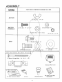
A SSEMBL
LOCATION
Y
PARTS
BAG
CONTENTS
SHOWN
FULL
SIZE
BA TTER Y
_ut\_
I/4
_ 20
/
m
i
BA TTERY
TERMINALS
(2) Hex Bolt.
1/4 . 20 x13/4
\
(2) Lockwasher
(_2)'_a;het
,,,,,,,,,,,
'/
SEA T
9/32x
5,_ x t6
,_
Ga
1/4
(2)Hex
Nut.
t/4
- 20
_w
\
/ _
11) Shoulder bolt'_//6
. 18
(1) Washer 17/32 x t-3/I6
x 12 Ga
t/2
Parts
Bag
Content.______s
Not
Shown
Full
S iz
F
!
Steering
Terminal
15 o Slope
Instruction
Wheel
Insert
Guard
Sheet
(2) Keys
Steering Column
(6) Batter}, Caps And
Instructions
ASSEMBLY
To assemble
tractor you will need:'
CAP
/
(2)
7/16"
(I)
1/2" Wrench
(1) 3/4"
NOTE:
Utility Knife
Wrench
RIGHT HAND
(R,H)
DETERMINED
WHILE
AND LEFT HAND
FROM
SEATED
WEAR
.,,,,
Tire Pressure Gauge
Screwdriver
Wrenches
Hi_" ARE
OPERATORS
P(_SITION
I!t
O
1_
I""
.........
i'
EYE AND FACE SHtELI_
\
f,
__"F_IGURE
OBSER
2
VE SA FETY
\,
\
\
r
b
c
Allow battery to stand and settle for at least thirty
minutes.
If the level of acid falls below the point
described in step (a), add more acid untif the correct
leve! is reached
Install the battery caps, found in the
bag of parts, to co ver the vent tubes. Wash the top of
the battery with water to remove any acid, then wipe
Neutralize e_cess batteryacidfordisposafbyadding
it to four inches of water in a five gallon plastic
Tighten shoulder bolt using a I/2" wrench. NOTE:
THE SHOU_DER
BOL T WILL BE LOOSE IN THE
SEAT SLOT_
Tighten
ma_Jme
screw,
tockwasher
and flat
washer
d
using\a3
,"4"
wrench
Place seat in o_erattngposltfon
and press ctutct\/ brake pedal
operating
e
dry
e
.so
\
F
Ct_eck battery case for leakage to make sure that no
damage has occured in handling,
forward or backward
reach Clutch 'Brake
(Fig 3)
seat on seat pan Screw he_ head machme
tockwasher
and flat washer
ln_o .seat (Fig
3) S ew shoulder
bolt into seat (F!g ,3)
MachH\e
screw, shoulder
bolt and washers
(shown
futf s_ze an page 6)
found h\ bag of parts
from side to side to
d
U-
stall Seat°
be adjusted
operator can comfortably
safely operate tractor
Fill each ceil with battery acid
Add the acid until it
reaches the bottom of the vent tubes (Fig 2) Do not
add the acid beyond this level or the additional acid
can come out when the battery is charged
PRECA
_, REQUIRED
Check the acid
h
. after, the battery is charge,d. If the acid
as fallen t_etow the correct le vet, add dis tilled
or iron free water.
Fill and charge battery (before installing),, NOTE,, SEE
DETAILED INSTRUCTIONS PACKAGED WITH BATTERY
VENT CAPS FOUND IN BAG OF PARTS
After cells are filled, tilt battery
release air bubbles
"
;TED tN BI
Prepare Battery
b
b ',_,-'_
_-;J_-'_'!
_mmendedthat the batterybe charged
use. Use .a 12 voft batfery char ge_
t_attery a_ a ra_e of 6 amperes tar 7
flare
READ THE INSTRUCTIONS
INCLUDED WITH
THE BATTERY
VENT
CAPS IN THE BAG OF PARTS
ALWAYS WEAR GLOVES, CLOTHING
AND GOGGLES TO PROTECT YOUR
HANDS, SKIN AND EYES,
a
'i
i_
c_ntainer
Stir with a wooden or plastic paddle while
a_ding baking soda until the addition of more soda
c_uses no more foaming
WASH HANDS
IF ACClDENTALLY_IN
OR CLOTHING\IMMEDIATELY
WITH BATTERY
CONTACT
ACID_
DO NOT SMOKE; FUMES FROM",,
CHARGED
BATTERY
ACID
ARE ,,,,.
EXPLOSIVE
.,,
2.
:[-7!
t!! !_R _ iJ
positio_
Sit on the seat
all the way do wn If
ls__
not comfortable,
To adjust
Raise seat Loosen
Shde seat to desired posltmn
screw securely
adjust
seat
machme
screw
hghten
machtne
WASHER MUST BE TIGHTENED SECUREMACHINE
SCREW-LOCKWASHER-FLAT
LY TO PREVENT MOVEMENT
OF SEAT,
7
ASSEMBLY
4. Check Tires
Check the air pressure in the tires Tires with too much air
pressure will cause the unit to ride rough. The wrong air
pressure wifl also keep the mower from cutting level The
corr ect air pressure is shown on the side of the tires ff the air
pressure is not shown, set to pressures shown in the REPAIR
AND ADJUSTMENT section. (page 14).
5.
Install
Battery
1
POSITIVE
B,_T
T_: Ry
BEFORE
INSTALLING
BATTERY,
REMOVE
METAL
BRACELETS,
WRISTWATCH
BANDS, RINGS, ETC_
FROM YOUR PERSON°
TOUCHING
NOTE:
\
NEGATIV_
BATTERY
NEGATIVE
WASHER
HEX
b
I
j
FIGURE3
THESE ITEMS TO BATTERY
TERMINALS COULD RESULT IN BURNS,
a
/
--
Lift seat (Fig 3)
Lower battery into fender weft with battery terminals
toward front of tractor (Fig. 3),. Make sure battery
rests in battery tray (Fig 4)
\
BOLTS
TERMINAL
NEGATIVE
CABLE(BLACK)
NUT
ER
WASHER
POStTIVE
/
BE SURE BATTERY DRAIN TUBE IS SECURELY
ATTACHED TO BATTERY TRAY DRAIN
POSITIVE
CABLE
(RED)
POStTIVETERMINALMUSTBECONNECTED
FIRST
TO
PREVENT
SPARKS
FROM
ACCIDENTAL
GROUNDING
HE,
x Nut
Connect RED battery cable to positive (+) battery
terminal with hex bolt, flat washer, lockwasher and
hex nut (shown full size on pg 6) found in bag of
parts. Tighten securely with two 7/t6" wrenches.
(Fig. 4)
d Connect BLACKgroundcable to negativ e (-) battery
terminal with remaning hex bolt, flat washer, lockwasher and hex nut (shown ful! size on pg. 6) found
in bag of pails.. Tighten securely. (Fig 4)
e
To prevent corrosion, apply grease to the battery
terminals after installing cables..
f . Using the key hole on one side of the battery support
(Fig 6) slide battery bolt into frame key hole (head of
bolt down). Fasten the battery bolt to the terminal
guard using internal/externa! iockwasher; wing nut,
(shown full size on pg. 6) as shown in Fig.. 5
g. Assemble the remaining battery bolt to other side of
battery support and fasten terminal guard to it with
remaining internal/externa! Iockwasher and wing
nut, (Shown full size oft pg. 6).. Tighten wing nuts
securely by hand (Fig. 5)..
NOTE: KEEP TERMINAL ACCESS DOORS CLOSED
WHEN NOT IN USE,
_ _
,
c
CAUTION:
FIGURE
4
WING
INTERNALIEXTERNAL
NUT
LOCKWASHER
TERMINAL
GUARD
WING
NUT
INTERNAL/
EXTERNAL
LOCKWASHE
_
.,_
R
BATTERY
BOLT
SUPPORT
FIGURE
5
6. Maintenance After First 2 Hours (Two Mowings)
Changing oil after the first two hours (or two mowings) wi!f
help eliminate break-in residue which might be damaging to
your engine.
DO NOT START ENGINE UNTIL YOU HAVE
REVIEWED THE OPERATION SECTION OF
THIS MANUAL
8
OPERATION
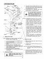
KNOW YOUR TRACTOR
READ THIS OWNER'S MANUAL BEFORE OPERATING YOUR LAWN TRACTOR, If you understand the unit and its
operation, you will achieve efficient a ndpeak performance. While reading the manual, compare the illustrations with your Lawn
Tractor to famifiarize yourself with the location of various controls and adjustments Study the operating instructions and safety
precautions thoroughly to insure proper functioning of your Lawn Tractor and to prevent injury to yourseff and others Be sure
to pay strict attention to all warnings and cautions. they are included for your safety Save this manual for future reference
Indicator
Lights,
Clutch
Light
Switch
Switch_
Ignition
Clutch/Brake
Pedal
Choke
Throttle
Control
Depth
Adjustment
Knob
l Zf
!
Parking Brake
Gear Shift
Lever
1
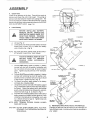
A TTA CHMENT LIFT LEVER: Use the attachment lift lever
to raise and lower the attachment mounted to .your tractor,
Pull lever back slightly and push button, then move the lift
lever forward to lower attachment
A TTA CHMENT CL UTCH S WITCH: Puff switch out and up
to engage attachment. There will be an engine hesitation as
the clutch engages.
GEARSHIFT: Press the clutch/brake pedal down firmly and
move gear shift lever to desired speed
INDICA TOR LIGHTS: "DEPRESS FOOT PEDAL "indicates
that the clutch/brake pedal must be depressed before the
engine will start, "DISENGAGE ATTACHMENT" indicates
that the attachment must be disengaged before t!;e engine
wilt start, "BATTERY DISCHARGING" indicates there ss
insufficient battery charging
CHOKE: To start a cold engine, engage choke bY moving
throttle control lever to "FAST" detent, then right & upward to
"CHOKE" position..
CLUTCH!BRAKE
PEDAL:
The pedal has 2 functions; a
clutch and a brake.. To engage the brake push the pedal
completely down
DEPTH ADJUSTMENT KNOB: Use the height adjustment
knob to adjust the mower height. With the attachment fift lever
in the "up"position, turn knob clockwise (,_"k) to raise cutting
height and counterclockwise (_)
to Iower cutting height.
IGNITION: Place key in ignition and turn to the right to start
The switch spring returns from the start position
LIGHT SWITCH:
Turns the headlights on and off..
PARKING BRAKE:
To set the parking brake, push the
clutch/brake pedal completely down, Hold the parking brake
lever in "Engaged"position and release pressure from pedal
Clutch!brake pedal will remain in brake position
THROTTLE/CHOKE
CONTROL:Use the throttle control
to increase or decrease the speed of the engine, and to
choke the engine for starting. Push control to the
right and forward to choke
OPERATION
a
AIR
SCREEN
This engine has been shipped filled with summer
weigh t oil (For cold weather operation see chart page
16)_ Check engine oil leveL Refer to REPAIR AND
ADJUSTMENT section.. ( page 16).
Fill fuel tank (Fig.. 6).. Use fresh, clean, regular
unleaded gasoline. Capacity is 5 quarts
b.
FUEL
CAP
FILL TO BOTTOM OF GAS TANK
FILLER NECK. DO NOT OVERFILL.
WIPE OFF ANY SPILLED OIL OR
FUEL. DO NOT STORE, SPILL OR USE
GASOLINE NEAR AN OPEN FLAME°
FILLER
FIGURE
6
EXPERIENCE INDICATES THAT ALCOHOL
BLENDED FUELS (CALLED GASOHOL OR
ii USING ETHANOL OR METHANOL) CAN ATTRACT
MOISTURE
WHICH
LEADS TO
SEPARATION AND FORMATION OF ACIDS
DURING
STORAGE
ACIDIC
GAS CAN
DAMAGE THE FUEL SYSTEM OF AN ENGINE
WHILE IN STORAGE
/O_L DRA_N
ATTACHMEIT
CLUTCH
S_ITCH
THROTTLE
CONTROL\
I
LE VE R
\"1
,\
PARK|NG
BRAKE
FtGURE7
GEAR
Stopping
NOTE:
SHIFT
NEVER USE ENGINE OR CARBURETOR
CLEANER PRODUCTS IN THE FUEL TANK
OR PERMANENT DAMAGE MAY OCCUR.
LEVER
Your Tractor
REMOVE
KEY WHEN
LEAVING
PREVENT UNAUTHORIZED
TRACT_
TO
/
/
B,
Push clutch-brake pedal into full "BRA!_E" position,
Keep your foot on pedal.
b,. Place attachment clutch switch in "DISENGAGED"
Position..
USE
Move gear shift lever to "NEUTRAL"position_
d_ Place parking brake in "ENGAGED" position and
release pressure from clutch/brake., Pedal should
remain in "BRAKE"position..
e. Move throttle control to "S" (slow) position..
L
Turn ignition key to "OFF"position. Never use choke
to stop engine,
The Engine
3.
Preparing The Engine
LEARN TO START,
STOP AND RE-
VERSE YOUR TRACTOR
OPEN AREA.
IN A LARGE,
10
throttle control lever (Fig. 7) past "FAS T"to the
a.
b
C
2.
TO AVOID ENGINE PROBLEMS, THE FUEL
SYSTEM SHOULD BE EMPTIED BEFORE
STORAGE FOR 30 DAYS OR LONGER DRAIN
THE GAS TANK, START THE ENGINE AND
LET IT RUN UNTIL THE FUEL LINES AND
CARBURETOR
ARE EMPTY
USE FRESH
FUEL NEXT SEASON SEE STORAGE INSTRUCTIONS
FOR ADDITIONAL
INFORMATION
Turni_tfitionkeyto
as engine starts.
"START'andreleasekeyassoon
\
CAUTION:
c.
DO'NOT RUN STARTER CONTINUOUSLY
FOR MORE THAN FIFTEEN SECONDS PER
MINUTE.
ff engine does not start after four or five #ies, move
throttle control lever to "FAST" position, wait a few
minutes and try again_ If the engine does not start
after four or five more tries, see the TROUBLESHOOTING Chart. (page 24).
OPERAON
d
e.
After the engine starts move throttle control lever
slowly to the "SLOW" position.
To start a hot engine move the throttle control lever
to a position between "FAST" and "SLOW".
DEPTH
ADJUSTMENT
KNOB
LiFT
LEVE
**HIGHEST"
READ THE OPERATING
"SAFETY RULES"
BEFORE
YOURCAREFULLY
MOWER.
POSITION
CAUTION:DO NOT ADD ADDITIONAL WEIGHT TO THE
TRACTOR OTHER THAN THE OPTIONAL
WHEEL WEIGHTS°
EXCESSIVE WEIGHT
MAY OVERLOAD
AND DAMAGE
THE
TRANSMISSION.
ALWAYS
WEAR
SUBSTANqltAL
R
I LOWEST
)POSITRON
FOOT _
//
WEAR
ANDTHAT
AVOID
LOOSE
FITTING
CLOTHING
COULD
GET CAUGHT
IN MOVING
PARTS
R H
RUNNER
;HARGE
GUARD
1
2
.3
4
5
6
7
8
9
t0
1t
TO AVOID INJURY
Read,_ owner's manual
CAUTION
Know location and function of al! controls
Keep guards, safety shield and switches in place
and working
Remove objects that can be thrown by blades
Do not mow when children and others are around
Never carry children or passengers
Always took behind machine before backing
Do not mow where machine can tip or slip
If machine stops going uphill, stop blades and back
slowly down
Be sure blades and engine have stopped before
placing hands or feet near the blades
Remove key when leaving machine
MAKE SURE PARKING
TRACTOR
SECURE-,
BRAKE WILL
FIGURE
a
Movetheattachmentliftlevertothehighpositionand
adjust height of cut to mid range See Fig 8
b
Start the engine,
C
Move the throttle lever to mid range position Select
a low (1st or2nd) gearuntilyou become more familiar
with the operation of the unit,
Operating
(See Starting the Engine)
HOLD/
d _
NEVER
PLACE
HANDS
OR FEETIIN
OR UNDER
ANY YOUR
POWERED
ATTACHMENX
OR NEAR ANY
MOVING
PART WHILE
TRACTOR
OR ANY POWERED ATTACHMENT IS RUNNING.
4,
8
Slow!y release clutch brake pedal and proceed to the
Lmowing area
bop the unit, then select a mowing speed..
Speed Selection Guide page 12h
L
Move throttle lever to half throttle and move attachment clutch switch to engaged position.
g
Slowly release clutch brake pedal.,
h
Move throttle lever to fast position.
i.
Observe height of cut and readjust as desired.
Your Lawn Tractor & Mower
DO NOT OPERATE THE MOWER WITHOUT
EITHER THE ENTIRE GRASS CATCHER,
ON MOWERS SO EQUIPPED, OR THE
DEFLECTOR SHIELD IN PLACE..
NOTE: THIS TRACTOR
IS EQUIPPED
WITH AN
OPERATOR
PRESENCE
SENSING SWITCH
ANY ATTEMPT BY THE OPERATOR TO LEAVE
THE SEAT WITH THE ENGINE RUNNING AND
THE ATTACHMENT CLUTCH SWITCH ENGAGED
WILL SHUT OFF THE ENGINE,
11
CAUTION:
(See
BEFORE YOU MOVE THE GEAR SHIFT
LEVER, COME TO A COMPLETE STOP. FAILURE TO DO SO CAN RESULT IN GEAR BOX
DAMAGE.
OPERATION
,.
NOTE: TIRE CHAINS CANNOT BE USED WITH
THE MOWER ATTACHED,
a.. Mower should be adjusted properly front to back and
side to side for good mowing performance Refer to
REPAIR AND ADJUSTMENT section. (page 22)..
b
f
C,
FIGURE
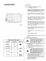
SPEED
SELECTION
FUNCTION
GEARSHIFT
Normal
Mowing
2or3
Heavy Mowing
1 or2
Snow Blowing
1
When mowing large areas (Fig 9 ), start by turning
to the right so that the clippings will discharge away
from shrubs, fences, driveways, etc._ After two or
three rounds, mow in the opposite direction making
left hand turns until finished.
e
If grass is extremely tall, it should be mowed twice
The first time cut relatively high, the second time to
the desired height.
f
The left hand side of mower should be used for
trimming..
g.
See Speed Selection Guide..
h.
Do not mow tall, dry grass ever 6 inches tatl. It is a fire
hazard.
Operating
4-6
The Tractor On Hills
DO NOT' DRIVE UP OR DOWN HILLS
WITH SLOPES GREATER THAN 15 °
AND DO NOT DRIVE ACROSS ANY
SLOPE. REFER TO PAGE 47,
GUIDE
THROTTLE
a.. Move gear shift lever to "l st" geat before .starting up
or down hills.
b AVOID STOPPING OR SHIFTING ON HILLS..
c. If slowing is necessary, move throttle controf lever to
slower position
FAST
LEAVE ENOUGH ROOM WHEN STOPPING AND STARTING TO ALLOW
SLIGHT TRACTOR ROLL DOWNHILL
AS CLUTCH-BRAKE
PEDAL MOVES
THROUGH CLUTCH POSITION.
Snow Blade
Transport
Drive so that clippings are discharged onto the area
that has been cut Have the cut area to the right of
the machine,. This witl result in a more even distribution of clippings and more uniform cutting,,
d,
9
6.
UsetherunnerontheRH.
sideasaguide;thebfade
cuts approximately an inch outside the runner (Fig
8).
d,
SLOW FAST
e.
f.
12
If stopping is absolutely necessary, push clutch/
brake pedal quickly to brake position,
To restart tractor movement, make sure tractor is in
the lowest speed range ("1st" Gear) and release
clutch.brake pedal SL OWL Y_
Make aft turns gradually.
MAINTENANCE
To keep your tractor
running
better, longer,
perform necessary
service using the folio wing
maintenance
schedule:
With
Every
BEFORE MAKING ANY INSPECTION,
ADJUSTMENT, OR REPAIR:
1_ PUSH CLUTCH/BRAKE
PEDAL
COMPLETELY DOWN_
2_ MOVE GEAR SHIFT CONTROL
LEVER TO NEUTRAL POSITION,
3
PLACE PARKING BRAKE IN "ENGAGED" POSITION. REMOVE
FOOT FROM PEDAL
4,, DISENGAGE
ATTACHMENT
CLUTCH SWITCH.
5, SHUT OFF THE ENGINE,
6, MAKE ABSOLUTELY
SURE THE
BLADES
AND
ALL
MOVING
PARTS
HAVE
COMPLETELY
STOPPED,
7_ DISCONNECT THE SPARK PLUG
WIRE
FROM
THE
SPARK
PLUG
AND
KEEP
WIRE
AWAY
FROM
THE
SPARK
PLUG
TO
PREVENT
INJURY
FROM ACCIDENTAL
STARTING
BE CAREFUL TO AVOID TOUCHING HOT ENGrNE OR MUFFLER
COMPONENTS
Mowing
Make sure all nuts on bolts are tight and cotter pins and
retainer springs are secure
Observe all safety precautions,
Keep tractor well lubricated (refer to page 17)
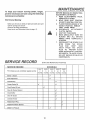
SERVICE
SERVICE
RECORD
(Enter Dale Maintenance
RECORD
Performed)
SCHEDULE
FIRST
EVERY
EVERY
I EVERY
/ EVERY
2
HOURS
5
HOURS..
25
HOURS
150
I HOURS
/
Fill in dales as you complete regular service
Blades - sharpen
€
Brake Adjustment
v"
Check
Change
100
HOURS
,/
Battery
Engine OIi
=
Check
Engine
Oil level
Clean Air Cleaner
Check
....
,,,
,, ........
€
€
Element
Muffler
€
, ......
Clean Air Screen
V
Lubrlcale Tractor
€
Replace Spark Plug
€
Replace Air Cleaner Element
€
Check Tire Pressure
€
13
REPAIR
AND ADJUSTMENT
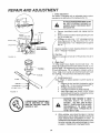
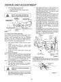
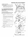
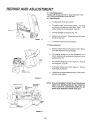
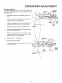
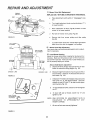
1_ Brake Adjustment
This tractor is equipped with an adjustable brake system
mounted on the right side of the transax/e (Fig, 10),
IF TRACTOR REQUIRES MORE THAN
SIX FEET STOPPING
DISTANCE
IN
HIGHEST GEAR, THEN BRAKE MUST
BE ADJUSTED,
a
JAM
BRAKE
OPERATING
NUT
NUT
A
b.
ARM
(WITH
BRAKE
Depress clutch/brake pedal and engage parking
brake
Measure distance between brake operating arm and
nut "A" on brake rod
ce is other than 1-1/2", disengage parking
brake, l_osen jam nut tFig. I0) and turn nut "A until
distance _ecomes I- I,/2", Retighten jam nut against
Nut "A'I. '_\
PARKING
I
ENGAGED]
Road test tractor for proper stopping distance as stated
\above
FIGURE
Readjuit if necessary..
2.\ Tire Care
/
M_ntain tire pressure in front at 14 PSI and rear tires at !2
10
3o Bl_d,
For be_t
blades c_
gnnding _
25 hours
mower:, l_
MANDREL
ASSEMBLY
twom_in_.,_
/
/"
/
Thesandwearsthebladeawayrapidly.
//a
Blad_ Replacement
Raise mo_zet to highest position to permit access to
blades\
1. Remove the hex head bolt, lockwasher and flat
/
,_
2.
3
4.
FIGURE
:are/
_,suf_smower blades must be kept sharp. The
be/_harpened with a few strokes of a fife. or on a
e,_l We suggest they be .sharpened after every
Ymowing Do not attempt to sharpen while on
_u mow in sandy soil check the blades after each
11
was_er (Fig.. 11) (turn counterclockwise)(_-'x)
RemOve and discard old blade.
Clean_op and bottom of mower housing.
Install &ew blade with SHARP EDGE DOWN
and secu"m with flat washer, lockwashet and hex
head bolt\TIGHTEN SECURELY
ALWAYS
USE GRADE
5 HEAT
TREATED
BOLTS
TO ATTACH
BLADES.
DO NOT USE PLATED
BOLTS. CHECK BOLTS IN BLADES
OCCASIONALLY
TO MAKE SURE
BOLTS ARE TIGHT, TORQUE BOLTS
TO 30 - 35 FT.- LBS.
A GRADE 5 HEAT TREATED BOLT
CAN BE IDENTIFIED
BY THREE
LINES ON THE BOLT HEAD AS
SHOWN AT" LEFT.
b,
14
When grinding, care should be taken to maintain
blade balance and the blade should be checked for
proper balance before reinstallation on mower: An
unbalanced or bent blade will cause excessive vibration when running, and eventual damage to mower
or engine. Replace bent or damaged blades..
REPAIR AND ADJUSTMENT
C,
To check blade balance, drive a nail into a beam or
wall
Leave about one inch of the straight nail
exposed Place center hole of clean blade over the
head of the nail (Fig 12) NOTE: CENTER HOLE
OF BLADE ON NAIL, IF BLADE IS PROPERLY
BALANCED, BLADE SHOULD REMAIN IN POSITION SHOWN IN FIG. 12 IF EITHER ENDOFTHE
BLADE MOVES DOWNWARD, BLADE IS NOT
BALANCED
SHARPEN THE HEAVY END UNTIL
BLADE IS BALANCED.
4, BATTERY
Jf
f
CENTER
.....
/
HOLE
I
I
\
BLADE
I
CARE
FIGURE
12
Check Battery
a
Battery acid solution level in each battery cell should
be even with bottoms of vent tubes in cells (Fig 13)
Add ONLY distilled or iron free water if necessary
NOTE: DO NOT OVERFILL
b
c.
d
e
Keep battery and terminals clean
Keep battery bolts tight
Keep vent caps tight and small vent holes in caps
open
Recharge at 6 amperes for t hour if necessary
CUT
AWAY
VIEW
VENT
Clean Battery and Terminals
Corrosion and dirt on the battery and terminals cause the
battery to "leak" power and hinders the operation of the
charger
BATTERY
VENT
TUBE
LIQUID
LEVEL
LEAD-ACID BATTERIES GENERATE
EXPLOSIVE GASES. KEEP SPARKS,
FLAME AND SMOKING MATERIALS
AWAY FROM BATTERIES. ALWAYS
SHIELD YOUR EYES AROUND
BATTERIES.
/
FIGURE
a
b
Remove terminal guard
Disconnect BLACK battery cable, then RED battery
cable, and remove battery from tractor,
c
Wash battery with four tablespoons of baking soda to
one gallon of water NOTE: BE CAREFUL NOT TO
GET THE SODA SOLUTION INTO THE CELLS,
d
Rinse the battery with plain water, dry and reinstallon
tractor
e Clean terminals and battery cable ends with wire
brush until bright.
f
Replace battery cables, connecting RED battery
cable to positive terminal first, then BLACK battery
cable to negative terminal
Coat terminal connections with grease after installation of cables
g.. Replace terminal guard.
15
CAP
13
BATTERY
CELL
ADJUSTMENT
Capacity is 1-1/2 quarts,. NOTE: DO NOT OVERRLL
Dipstick assembly must be securely tightened into tube at all
times when engine is operating
AIR
SCREEN
IMPORTANT:
FUEL
CAP
TO AVOID DAMAGE TO THE
STARTING SYSTEM, USE SAE
5W30 OIL WHEN THE TEMPERATURE FALLS BELOW 32 °.
Recommended SAE Viscosity Grades
Determine temperature range expected before next oif
change,. Aft oil must meet A,P°I,,service classification SD,
SE or_£F_ .... _.
.af Open petcock to drain engine oil,.
/
Tighten p_(cock finger tight to close,
FIGURE
14
/
I
b
I
Add oil through the oil filler cap/dipstick (Fig_ 14)_
!
20 o_ DO!
s2o
600
'r°ii
II
Check,
NOTi
eoo 700°
.......
,.
'lne 0tl Level
DO NOir CHECK ENGINE
WITH ENGINE RUNNING.
OIL LEVEL
after stopping engine, check engine oil level
tra_ctot on level ground, Wipe dipstick (Fig,. 14) clean,
tight for a few seconds, remove and read oil
If necessary, add oil until "FULL "mark is reached, (See
NOTE: DO NOT OVERFILL
HEX
Clean Air Cleaner Element
(Fig. 15)
a Remove two cover knobs and remove air cleaner
cover
\b Remove foam pre-cleaner.
--Wash
pre-cleaner
in liquid
detergent
and
warm water to remove d#t
Wrap pre-cleaner
in cloth and squeeze dry,
Wipe foam with a light coat of engine oil
Do not
saturate.squeeze
in rag or towel to remove excess oil
c Remove two nuts from top of cartridge
d Remove cartridge
and clean air cleaner body
carefully
to prevent dirt horn entering
carbure.,
tot
e Clean cartridge
by gently tapping
on flat sur.
face
If very dirty, replace cartridge
f Reassemble
air cleaner
NUT
NOTE
Nuts holding
air cleaner cartridge must be in.
stalled with hber washers
down on cartridge
plate to
prevent dirt horn entering carburetor
Tighten nuts by
hand , Over tightening
could collapse cartridge
FIGURE t6
5. Change Engine 011
The best time to change engine oil is at the end of a day's
operation when all dirt and foreign materials are suspended
in the hot oil.
NOTE. NEVER
MOVED
16
RUN ENGINE
WITH AIR
CLEANER
RE-
REPAIR
8.
Clean Air Screen
ALWAYS
A
WEAR
EYE
PROTECTION
WHEN
PRESSED AIR,
AND
FACE
USING
COM-
AND ADJUSTMENT
11. Starting your Tractor With a Weak Battery
tf your battery is too weak to start the engine, it should be
recharged If '_iumpercables" are used for emergency starting, follow this procedure:
NOTE:
YOUR TRACTOR
IS EQUIPPED WITH A !2 VOLT
NEGATIVE
GROUNDED
SYSTEM
THE OTHER
VEHICLE MUST ALSO BE A 12 VOLT NEGATIVE
GROUNDED
SYSTEM.
Air screen (Fig, I4) must be kept free of dirt and chaff to
prevent engine damage from overheating.. Clean with a wire
brush or compressed air to remove dirt and dried gum fibers,,
9, Check Muffler
Inspect and replace damaged muffler and/or deflector as it
could create a fire hazard and/or damage
LEAD-ACID
CYLINDER
OR FINSHOT
AS MUFFLER,
CONTACT
DO NOT TOUCH
MAY CAUSE BURNS°
A
BATTERIES
GENERATE
EXPLOSIVE
GASES.
KEEP SPARKS,
FLAME
AND SMOKING
MATERIALS
AWAY FROM BATTERIES.
ALWAYS
WEAR
EYE
PROTECTION
WHEN
AROUND BATTERIES°
a
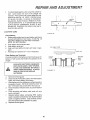
10 Lubricate Plvot Points
Place several drops of SA E 30 oil at points where parts move
against each other, especially
a,. Front axle pivot
b Hood hinges
c Foot pedal shaft (both ends)
d Lift shaft (both ends)
Connect each end of the RED cable to the POSITIVE
(+) terminals of each battery (taking care not to st:on
against chassis). (Fig, I6)
Connect one end of the BLACK cable to the
NEGATIVE (-) terminals of fully charged battery
b,,
Connect the other end of the cable to the L.H side
panel bolt (Fig, 17) NOTE, KEEP A WAY FROM GAS
TANK AND BATTERY
C
LUBRICATIONCHART
FRONT
(22)
AXLE
PIVOT
(_
SPINDLE
SPINDLE
O
WHEEL
BEARINGS
__:"t
BEARINGS
_WHEEL
_
GT,EROO
(_
MOWER
(1_
CLUTCH
BOTH
',-2../ FOOT
ENO,NE
PIVOT
ENDS OF
PEDAL
SHAFT
......
;%::,
//_{
OSL, TS.AFT
9
i l-':222_::2:22-:
_
(_SAE
MOTOR
OIL
Q
EXTREMEPRESSURE
LUBRICATING
GREASE
AMDEXNO
I, SEARS
PART NO 2557R
_
REFER
TO ENGINE
P' o'G
OIL SPECS
17
REPAIR AND ADJUSTMENT
d.,
DLsconnect cables in reverse order::
!
L.H Side Panel Bolt (Fig 17)
2, Negative terminals of fully charged battery
3
Positive terminals
d
e
DO NOT USE YOUR TRACTOR BATTERY TO START OTHER VEHICLES.
L.H, SIDE
PANEL BOLT
CLLrrCH
BRAKEPEDAL
"BRAKE"
PosmoN
""
PARKING
BRAKE
"ENGAGED'POSITION
._n=til engine begins to die,. Turn idle mixture screw
to a poir} i midway between these positions
With thro tte control lever in "SL OW"position, engine
should iee at 1750 RPM. If engine idles too slow,
push thr_ tUe control lever above idle and turn idle
speed sc ew one turn clockwise (F-_). Set throttle
control 14let at "SLOW" Repeat until satisfactory
idle is att tined
(\
CLUTCH/BRAKE
PEDAL
"CLUTCH'
POSIT!ON
FIGURE 17
"
,,DRIVE >"
POSITION
PARKING
BRAKE
' DISENGAGED'
POSITION
F_
b
c
ff engine idles too fast with throttle control lever in
"SLOW" oosition push throttle control lever above
idle and u_rnidle speed screw one turn coun!erclockwise (,_ "_).. Set throttle control lever at 'SLOW,
Repeat/until satisfactory idle is attained
I_OLE
12. Throttle Control Cable Adjustment
Never attempt to change maximum engine speed This is
preset at the factory and should only be changed by a
qualified service technician who has the necessary
equipment
CAUTION: BEFORE ANY ENGINE ADJUSTMENT, MAKE SURE AIR CLEANER IS CLEAN RemoveAif
Cleaner Assembly, while making adjustments.
a.
With throttle control lever in "FAST" position, turn
high speed mixture screw counterclockwise (P_\)
until engine runs "rough" then turn clock wise ( /-'_)
until engine begins to miss. Turn screw to a point
midway between these positions.
With throttle control lever in '`slOW"position,
hold
throttle lever so that idle stop screw is against carburetor; turn idle mixture Screw countercfockwise (F_)
until.engine runs "rough" and then turn clockwise
I
_
/
lUL_
STOP
MIXTURE
SCREW
THROTTLE
CABLE
/
/
DO NO
ADJU5
HOLES
A
With engine off, place Throttle Control in "FAST"
position.
Loosen Clamp Screw (Fig. 18). Adjust Throttle
Cable until holes "A" are aligned in governor control
plate and slide plate
Tighten clamp screw..
d
If holes do not align, repeat steps in throttle cable
adjustment
13. Carburetor Adjustment
IDLE SPEED
SCREW
HIGH
NOTE.: ADJUST THROTTLE CONTROL CABLE BEFOf_E
MAKING ANY ADJUSTMENT TO CARBURETOR,
a
With engine off turn high speed mixture screw clockwise ( f-_'_ ) closing finger tight ONLY, and turn
counterclockwise (_"-_\) 1-1/2 turns (Fig.. 18)
NOTE.: THE SCREW SEA T MA Y BE DAMAGED BY TURNING IT TOO FAR CLOCKWISE.
b
Turn idle mixture screw clockwise (,f_)
closing
finger tight only, and turn counterclockwise (_-_,)
1-½ turns (Fig 18)
c.
Start engine and allow to warm for five minutes,=
Make final adjustment with engine running and Gear
Shift lever in "NEUTRAL" position..
MIXTURE
SPEED
SCREW
PLATE.
SLIDE
GOVERNOR
PLATE
CONTROL
FtGURE18
14, Rep_ce Spark Plug
Replace s_ark plug at the beginning of each mowing season
or every 10_ hours, whichever comes first, Gap should be set
at 0030 inch (Fig 19),
FIGURE
t8
19
FtEPAIR AND ADJUSTMENT
15. Replace In-line Fuel Filter
ff fuel filter is clogged, obstructing fuel flow to carburator,
replacement is required,.
a.. With engine cool, remove filter and plug_ Fuel line
sections removed from both ends of fuel filter (Fig..
18).
b
Place new fuel filter in position in fuel fine,
ii,,
,_
_ ,#"k
ii.....
ii,ll,,i
i,illl
_ ...............................
i i ,ll,,,ll,i
AND THAT HOSE CLAMPS ARE PROPERLY
BE
SURE THEIR ARE NO FUEL LINE LEAKS !
INSTALLED.
/
f t
RETAINER
SPRING
FIGURE20
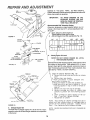
1,6 Motion Drive Belt Removal
The tractor drive belt may be replaced without tools. Park the
tractoronlevelarea,
Engageparkingbrake
NOTE: ABELT
INSTALLATION DECAL IS UNDER LEFT FOOTREST
a.
Remove mower
BELT
1
GUIDE
RETAINER
BRACKET
SPRING
BELT
/
(See mower section, Following
pages).
F,
/_
_\
/
b.. Remove two retainer springs from belt guide bracket/
below transaxte pulley. Remove bracket (Fig 20)_/
!
C
Swing belt guides away from belt, toward rear _f
_,_
tractor (Fig. 20).
/
1
d
Roll belt over top of transaxle pulley
e.
Rofl belt over engine pulley and off idler (Fig 22)
Release parking brake. Pull belt as far as possible
over top of clutch pulley..
21
g,
Reset parking brake
pulley (Fig 22)..
Puff belt over top of clutch
SHIFT
H. SIDE
Pull belt out through shift gate to remove from tractor
(Fig.. 21)
Install belt by reversing above procedure
GATE
ENGINE
PULLEY
h
DRIVE
BELT
SCHEMATIC
CLUTCH
/
NOTE: REPLACE ONLY WITH BELT LISTED IN T_flS
MANUAL.
ULLEY
L_H
BELT
GUIDE
\
FIGURE22
VIEWED
19
FROM
" - REA R
BOTTOM
OF TRACTOR
SIDE
REPAIR
AND ADJUSTMENT
17. Fuse Replacement
Replace with 30 amp automotive - plug-in type fuse_ Location.: Tied to wiring harness under fuel tank
18. Hood Removal
FIGURE
a.
To raise hood, rift at rear of hood_
b..
To remove hood, grill and side panels, raise hood
and loosen one screw on each side panel.. (This
screw remains in the side panel) (Fig. 23).
c.
Unsnap headlight connection (Fig° 24)..
d
Stand in front of tractor. Grasp hood and tilt forward
and lift off (Fig. 24).
23
e.. To reinstall, reverse above procedure.
19 Mower Removal
a
Remove mower belt per instructions under "Mower
Drive Belt Removal" through step(c),
b.. Pul! retainer' springs out of rear suspension trunnions. Remove rear suspensions trunnions from hft
brackets (Fig. 25),.
¢_ Pul! retainer spring out of rear' hinge pin. Remove
rear hinge pin. (Fig. 25)
WIRE
CONNECTION
d
Pull retainer spring out of front hinge pin. Remove
front hinge pin (Fig.25)..
e.
Use lift levef to raise suspension arms. Slide mower
out from under tractor:
FIGURE 2 4
NOTE:
RETAINER
IF AN ATTACHMENT
OTHER THAN THE MOWER
DECK IS TO BE MOUNTED ON THE TRACTOR,
THE L.H. AND R.H. SUSPENSION ARMS (FIG. 25)
SHOULD BE REMOVED FROM TRACTOR.
FIGURE 2 5
2O
REPAIR AND ADJUSTMENT
20° Mower Installation
Your Mower installs without the use of tools. Raise Attachment
Lift Lever to its highest position
Turn height adjustment
knob
to lowest
position
Mower
\
a
Slide
Side
b
Install front hinge pin through axle and parallel rink
(Fig26). Secure with retainer spring,
c
install rear hinge pin through
parallel link (Fig 26) Secure
under
tractor,
guard
to R H
Slide trunnions through lift brackets holes and secure
with retainer spring (Fig 27)
around
to lower
RH
suspension
FIG_
e
belt routed
mower
pulley, roll belt over mower drive pulley
schematic
decal on mower housing
g.
FRONT
HINGE
PiN
mower lift brackets and
with retainer spring
Move
With
lift lever forward
discharge
d
f
RETAINER
SPRfNGS
PARALLEL
LINK
pulley
arms
REAR
HINGE
pIN
26
and idler
(Fig 27)
Drive
Rol! belt over L H mower pulley
h.
Use lift lever to raise mower
i
Turn height adjustment
middle of its travel
knob clockwise (F-_)
SUSPENSION
ARM
IDLER
PULLEY
to the
RETAINER
SPRING
/
//7
TRUNNION
_,iJ
LIFT
BRAC
27
21
MOWER
DRIVE
,
RH
MOWER
PULLEY
ET
REPAIR AND ADJUSTMENT
21o Mower
Drive Belt Replacement
ENGINE
REPLACE
PULLEYs=
ONLY WITH BELTS SPECIFIED
IN THIS MANUAL,
IDLER
BELT
a
Place attachment
tion
b
Turn height adjustment
to lowest position
c
Move attachment
lift lever (Fig 28) forward
mower to its lowest position
d
Roll belt off mower
drive pulley
e
Remove
(Fig29)
mower
f
To install mower drive belt, reverse above procedure
Make sure drive belt is engaged in all pulleys
L.H_
clutch
switch in "disengaged"
posi-
MANDREL
FIGURE
EXTENSION
SPRING
29
LiFT LEVER
PLUNGER
LIFT
LEVER
SIDE TO.SIDE
ADJUSTMENT
_'__
BOTTOM
BOTTOM
OF CURL
\
A
__i
FIGURE
LINE
b
LINE
30
d
e,,
, _
U
I11
II
I
IIII
I
pulleys
and
idler
pulley
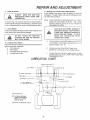
Measure height from bottom of curl to ground line at
front of mower. Distance "A" should be the same on
both sides (Fig. 30).
if distance "A"needs to be changed, snap out access
hole cover on L,Ho side above footrest.. Use 9/16"
wrench on nuts "B" and "C" at side-to-side adjustment trunnion (Fig. 31)._
To raise left side of mower, loosen nut "B'and tighten
nut "C".
To lower left side of mower, loosen nut "C" and
tighten nut "B".
NOTE: ONE ROTATION OF ADJUSTMENT NUTS IS
EQUIVALENT
TO APPROXIMATELY
3/16"
HEIGHT CHANGE
II
f_
FIGURE
(Fig,29)
Side-to-Side Mower Adjustment
a. Depress lift lever plunger and use lift lever to raise
mower to maximum cutting height, (Fig 30)..
C,
,_
to lower
23. Level Mower Housing
Adjust the mower while tractor is parked on level ground or
driveway. Make sure tire pressures are 14 PSI in front tires
and 12 PSI h_rear tires If tires are overot underinftated, you
will not properly adjust your mower.
CURL
GROUND
from
(/F_
22, Mower Drive Belt Adjustment
Your tractor' has a self tensioning belt system and no adjustment is necessary.
T
GROUND
belt
knob counterclockwise
31
22
Be sure all nuts are securely tightened.
)
REPAIR
AND ADJUSTMENT
Front.To-Rear Mower Adjustment
a. To obtain the best cutting results, .your mower housing should be adjusted so the front and rear flange
distance "D" (Fig.. 32) is 1/2" lower in front when the
mower is positioned in the highest cutting position.
NOTE
MEASURE
DISTANCE
"D" FROM
GROUND LINE TO BOTTOM OF CURL ON RIGHT
REAR FLANGE AND COMPARE TO DISTANCE
"D" AT BOTTOM OF CURL ON RIGHT FRONT
FLANGE.
b
To raise rear of mower, loosen nut "E" on both rear
suspension arms (Fig 33)Screw
both nuts "F" up
EQUAL NUMBER OF TURNS (Fig. 33).
c.. When distance "D" is 1/2" lower at front than rear
d
e.
REAR
SUSPENSION
tighten nuts "E"..
To lower rear of mower, loosen nut "F" on both rear
suspension arms an EQUAL NUMBER OF TURNS
(Fig. 33).
When distance "D'" is 1/2'° lower at front than rear,
retighten nuts "E"
FIGURE
32
.........
j
/
R
NUT
AR
"E
SPENSION
s[
T IUNNION
NOTE: WHEN ADJUSTING REAR SUSPENSION TRUr
NIONS, ALWAYS ADJUST BOTH EQUALLY S D
MOWER WILL STAY LEVEL
NUT
F
REAR
SUSPENSION
ARM
LIFT
BRACKET
24. Storage
Remove mower from tractor for winter storage.
is to be stored for a period of time, clean it
al! dirt, grease, leaves, etc.. Give blades and underside of
housing a good coat of grease or rust preventative
Store in
a clean dry area.
A.
i
Fuel System
_W
il
FIGURE33
th clean engine
oil, (See chart page t6)
It is important to prevent gum deposits from forming in essential fuel system parts such as the carburetor, fuel filter, fuel
hose, or tank during storage Also, experience mdicates that
alcohol blended fuels (called gasoho! or using ethanol o
methanol) can attract moisture which leads to separation
formation of acids during storage Acidic gas can
fuel System of an engine while in storage To avoid
problems, the fuel system should be emptied
_f 30 days or longer
Cylinder
I
Remove spark plug
2
Pourone ounce of oil through spark plug hole
into
cylinder
Turn ignition key to "START position for a few
seconds to distribute oil
D_
ry
B1eplace
with new spark plug
rior to storage, clean terminals and top ol battery
2.
3.
Disconnect cable from positive side ot battery
After a period of time in storage, baltery may
require recharging
E, General Cleaning
Clean engine, battery, seat, finish, etc , of all foreign matter
F.
23
Store tn a Clean Dry Area
TROUBLESHOOTING
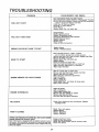
PROBLEM
CAUSE/REMEDY
Push Clutch/Brake
Pedal into Brake Position.
Move Attachment
Clutch
Switch
to "Disengaged"
Position
Fill Fuel Tank with Gasoline,
Check Fuel Line and Carburetor
(clean if necessary) Replace Fuel Filter
Check fuse for fault and replace
Recharge or replace Battery
Check Wiring
Replace Spark Plug and adjust gap
WILL NOT START
WILL NOT TURN
ENGINE CLICKS
HARD
Charge Battery
Replace Ignition
Switch
Depress Clutch/Brake
Pedal
Disengage
Attachment
Clutch
Replace Interlock Switch
Replace Solenoid
Replace Fuse
Check All Wire Connections
OVER
BUT WON'T
Replace Starter
Charge or Replace
START
MISSES
ENGINE
OR LACKS
POWER
Clean Air Screen
Add or change oil
Clean Engine Cooling Fins
Remove end clean Muffler or replace
Remove and clean Air Filter
Use fresh fuel and adjust Carburetor
OVERHEATS
Check Fuse, Switch and wire connections
Headlight Bulbs
mESENCE
Replace
Check
Fuse and replace
Replace Battery
Replace
Regulator
Replace Alternator
CHARGE
0 PERA TOR
Battery
Shift to a lower gear or reduce load
Remove and clean Fuel Tank; replace Fuel Filter
Remove and clean Air Cleaner
Make necessary
carburetor
adjustments
Clean Air Screen
Add or change oil
Replace Spark Plug
Check Spark Plug
and check for loose wires
Major Engine overhaul
NO LIGHTS
WON'T
Switch
Place Throttle
Control in "FAST"
position
and run starter several times to clear out gas
Remove and clean Fuel Tank and lines_ Replace Fuel Filter
Remove Air Filter and clean
Replace Spark Plug and adjust gap
Replace Battery
Check the wiring and Spark Plug
Drain Fuel Tank and C3rbureror.
use fresh fuel
Make necessary
adjustments
to Carburetor
Major Engine Overhaul
TO START
ENGINE
(SEE INDEX)
S YS TEM-WiLL
NO T SHUT
DO WN
Engage attachment
clutch
Check aft wire connections
Check seat switch Check operator
Check PTO Switch
WHEN
OPERA TOR LEA VES SEA T,.
Note: This tractor
is equipped with an operator presence sensing system, Any attempt by the operator to leave the seat with
the enigne running and the attchment
clutch engaged will shut
__d.o,wn,,,,the engine.
24
presence
relay
TROUBLESHOOTING
UNSATISFACTORY
MOWER PERFORMANCE
UNEVEN DISTRIBUTION
OF CLIPPINGS
MOWER
Install new Mower Drive Belt
Reinstall Mower
Drive Belt
Adjust Mower
Drive Belt
Replace Frozen Mandrel
Replace Frozen Idler Pulley
BLADES WILL NOT ROTATE
EXCESSIVE
MOWER
Replace
Replace
VIBRATION
WIND ROWING STRIPPING
OF GRASS CLIPPINGS
UNEVEN
.... Place _e'=C0_trol
in _;FAST"
position'
Check air pressure in tires
Check front to rear and side to side mower
adjustment
Use a slower ground speed
Check engines RPM's (refer to Carburetor
Adjustment)
Replace mower blades
Reinstall mower blades with top of blade up
Replace with proper mower blades
Re-adjust
mower drive belt
OR DROPPING
Bent or Unbalanced
Mandrel,
Straighten
Let grass dry out
Clean underside
of Mower
Readjust Mower
CUT OR SCALPING
Readjust
25
Mower
Blades
Deck or replace
Deck
AttachmentsThatAdd to the Usefulness of Your Craftsman Lawn Tractor
Searsoffersa wide varietyof attachmentsthatfit yourtractor.Manyof theseare listedbelowwith briefexplanationsof howtheycan help you,Thislist
wascurrentatthelimeofpublication:
however,it maychangein futureyears--more attachmentsmaybe added,changes(includingchangesin g_estock
number)may be madeinthese attachments,or somemay no longerbe available_
Mostof theseattachmentsdo not requireadditiona!hitchesor conversionkits (thosethatdo are indicated)and are designedforeasy attachingand
detaching_You mayorder these attachmentsat mostSearsretailstores,catalogsalesoffices,and throughthe catalog..
PERMANEXBAGGERlets you coltectgrasscIippingsand ]eavesfora heafthiernearer-lookinglawn..Two Permanexcontainershold 30-gallonplastic
bags. Stocknumber71-24940
LAWNSWEEPERSlet youcoIlectgrass clippingsand Ieaves
71o24030
30-in.
9.0 cu. fL
71-24032
32-in
10.0cu. ft.,
71-24033 High-Performance
7t-24038
32 in.
38-in.
115 cu. ft.,
12 5 cu..ft.
LAWNVACSforpowerfulcollectionsof heavygrassclippingsand leaves.,Wand
a_ment
71-2452
3HP
71-24353
4 cu. ft. /
71-24354
10 cu,.fL/
1,000lb,.
t
Haulingcart
71-24355
10 cu. fy
t,000 lb.
t
Dumpcart
CARTSmakehaulingeasy..
_
topick up debrisin hard-to-reachplaces.
12 b_k,,
/
71-26471chute
\
J
\
400 tb. \
Dumpcart
71-24356
14 cu. It.
!,250 lb
t
Dumpcart
ROLLERforsmootherlawnsurface.36-inchwide,18 inchdiameterwatertight drumholdsup to_90 lb.ofweight.Roundededgespreventharmtoturf..
Adjustablescraperautomaticallycleansdrum. Stocknumber71-_4084.
/
SPREADERiSEEDERS
makeseeding,fertilizing,and weedkillin_easy,Broadcastspreaders/_realso usefulfor granularde-icersand sand,
\
!
71-24194
Drop type,36 inch. 12 in semi-pneumatic
_heels t00 Ib.capcitysttel hopper_
71-24394
Broadcastsovera 5 to8 footswalh.70 lb capacitysteelhopper Nor_;orrosive
spreadingspinner,nylongearbox,stainlesssteel
\
shaft,
71-24395
t
'_
/
Broadcasts8 to10 foot swath.160Ib.capac_tyNo\{ustpolypro_lene hopperand impeller.Vinylhoppercovet.
\
/
CORINGAERATORtakessmallplugsoutofsoil toallowmoistureand nutrient\to c,_grassroots.36-inchswath.24 hardenedsteelcoringtips_t50
]b.capacityweight tray..Stocknumber7t-25351
\
/
AERATORpromotesdeep rootgrowthfor a healthylawn Tapered25" steelspit_ mountedon 10-in_diameterdiscspunctureholesin soilat close
intem_als
tolet moisturesoakit. Steelweighttrayfor increasedpenetrationStock_; tuber71-2435.
DETHATCHERloosensand flipsthatchand mattedleavestolawnsurfacefor east _(_kup.Twentyspringfineteeth_Usefultopreparebareareasfor
reseeding 40 inch rear mount:Stocknumber71-24313.38 inchfrontmount:S_c_ 1L_ber71-2430t,.
SPRAYERSuse12-voltDCelectricmotorthatconnectstothetractor
batteryo_ther 12-v_[tsource,Includes
boomsforautomaticsprayingwhenpulling,
and handheld wandfor spot spraying,Wandhasadjustablespraypattern/Forapplying_erbicides,insecticides,fungicides,and liquid fertilizers.
J
71-2458
50 psi maximumpressurewith 12 foot wand l_tk
71-24398
25 psi maximumpressurewilh 10 foot wan,_ength Spraysup to _8 feet with wand
SPrays up t_25 feet with warld,
/,
SNOWBLADEfor snowremovalonty.,14 inchhigh,42 inct_wide"bfadeclears38 inch palh_whenangled lefi or right. Raises,fowerswith sidelever..
Adjustableskids:replaceable,reversiblescraperbar. (Use,_ iire chains,wheelweights,o_,reardrawbarweight).Stocknumber71-24407.
SNOV',,q'HROWER
has40-inchswath.Drum-typeaugerh_ndlespowderyandwet/heavysno_. Mountseasily with simplepin arangement.Discharge
chuteadjuststo 210degreearcfrom tractorseat.6-inct_diameterspoutdischargessnowt0 to ,_0ft..Lift controlledat lractorseal (Usewith tirechains,
wheelweights,or rear drawbarweight).StockNo 71-24072.
',
TIRECHAINSare heavyduty; closelyspacedextra-largecrosslinksgive smoothride,outstandingt[action.StockNo. 71-24952..
WHEELWEIGHTSfor rear wheelsprovideneededtractionfor snow removalor dozingheavymaterials,In pairs_StockNo. 71.24434(30 Ib,.each)
TRACTORCABhasheavy dutyvinyl fabricovertubularsteelframe,ABSplastictop; clearplasticwindshieldoffers360 degreevisability.Hingedmetal
framedoorswitll catch,Keepsoperatorwarmand dry, Removevinyl and windshieldfor use assun protectorin summer°StockNo_71-24171,.
Opliona]accessoriesfor tractorcab: tinted/temperedsolidsafelyglasswindshiedwithhandoperatedwiper(StockNo.7t-26168); 12-voltambercaution
lightfor mountingon cab top(StockNo 71-26t89).
TRACTORCOVERprotectstractorfromweather,Madeof Evolution3 fabric (water_repellenL
extremelybrealhab]e,light weighLsoft, non-abrasive,
pliablein all temperatures,durable,stain-tear-puncture
resistant,will not shrinkor stretch).,StockNo_71-24601.
26